WO2019004177A1 - ヘリコプタ用の潤滑装置 - Google Patents
ヘリコプタ用の潤滑装置 Download PDFInfo
- Publication number
- WO2019004177A1 WO2019004177A1 PCT/JP2018/024131 JP2018024131W WO2019004177A1 WO 2019004177 A1 WO2019004177 A1 WO 2019004177A1 JP 2018024131 W JP2018024131 W JP 2018024131W WO 2019004177 A1 WO2019004177 A1 WO 2019004177A1
- Authority
- WO
- WIPO (PCT)
- Prior art keywords
- oil
- lubrication
- lubricating
- passage
- oil reservoir
- Prior art date
Links
Images

Classifications
-
- F—MECHANICAL ENGINEERING; LIGHTING; HEATING; WEAPONS; BLASTING
- F16—ENGINEERING ELEMENTS AND UNITS; GENERAL MEASURES FOR PRODUCING AND MAINTAINING EFFECTIVE FUNCTIONING OF MACHINES OR INSTALLATIONS; THERMAL INSULATION IN GENERAL
- F16H—GEARING
- F16H57/00—General details of gearing
- F16H57/04—Features relating to lubrication or cooling or heating
- F16H57/0412—Cooling or heating; Control of temperature
- F16H57/0415—Air cooling or ventilation; Heat exchangers; Thermal insulations
- F16H57/0417—Heat exchangers adapted or integrated in the gearing
-
- F—MECHANICAL ENGINEERING; LIGHTING; HEATING; WEAPONS; BLASTING
- F16—ENGINEERING ELEMENTS AND UNITS; GENERAL MEASURES FOR PRODUCING AND MAINTAINING EFFECTIVE FUNCTIONING OF MACHINES OR INSTALLATIONS; THERMAL INSULATION IN GENERAL
- F16H—GEARING
- F16H57/00—General details of gearing
- F16H57/04—Features relating to lubrication or cooling or heating
- F16H57/0434—Features relating to lubrication or cooling or heating relating to lubrication supply, e.g. pumps ; Pressure control
- F16H57/0442—Features relating to lubrication or cooling or heating relating to lubrication supply, e.g. pumps ; Pressure control for supply in case of failure, i.e. auxiliary supply
-
- B—PERFORMING OPERATIONS; TRANSPORTING
- B64—AIRCRAFT; AVIATION; COSMONAUTICS
- B64C—AEROPLANES; HELICOPTERS
- B64C27/00—Rotorcraft; Rotors peculiar thereto
- B64C27/04—Helicopters
- B64C27/12—Rotor drives
-
- F—MECHANICAL ENGINEERING; LIGHTING; HEATING; WEAPONS; BLASTING
- F16—ENGINEERING ELEMENTS AND UNITS; GENERAL MEASURES FOR PRODUCING AND MAINTAINING EFFECTIVE FUNCTIONING OF MACHINES OR INSTALLATIONS; THERMAL INSULATION IN GENERAL
- F16H—GEARING
- F16H57/00—General details of gearing
- F16H57/04—Features relating to lubrication or cooling or heating
- F16H57/042—Guidance of lubricant
- F16H57/0421—Guidance of lubricant on or within the casing, e.g. shields or baffles for collecting lubricant, tubes, pipes, grooves, channels or the like
- F16H57/0423—Lubricant guiding means mounted or supported on the casing, e.g. shields or baffles for collecting lubricant, tubes or pipes
-
- F—MECHANICAL ENGINEERING; LIGHTING; HEATING; WEAPONS; BLASTING
- F16—ENGINEERING ELEMENTS AND UNITS; GENERAL MEASURES FOR PRODUCING AND MAINTAINING EFFECTIVE FUNCTIONING OF MACHINES OR INSTALLATIONS; THERMAL INSULATION IN GENERAL
- F16H—GEARING
- F16H57/00—General details of gearing
- F16H57/04—Features relating to lubrication or cooling or heating
- F16H57/0434—Features relating to lubrication or cooling or heating relating to lubrication supply, e.g. pumps ; Pressure control
- F16H57/0441—Arrangements of pumps
-
- F—MECHANICAL ENGINEERING; LIGHTING; HEATING; WEAPONS; BLASTING
- F16—ENGINEERING ELEMENTS AND UNITS; GENERAL MEASURES FOR PRODUCING AND MAINTAINING EFFECTIVE FUNCTIONING OF MACHINES OR INSTALLATIONS; THERMAL INSULATION IN GENERAL
- F16H—GEARING
- F16H57/00—General details of gearing
- F16H57/04—Features relating to lubrication or cooling or heating
- F16H57/045—Lubricant storage reservoirs, e.g. reservoirs in addition to a gear sump for collecting lubricant in the upper part of a gear case
-
- F—MECHANICAL ENGINEERING; LIGHTING; HEATING; WEAPONS; BLASTING
- F16—ENGINEERING ELEMENTS AND UNITS; GENERAL MEASURES FOR PRODUCING AND MAINTAINING EFFECTIVE FUNCTIONING OF MACHINES OR INSTALLATIONS; THERMAL INSULATION IN GENERAL
- F16H—GEARING
- F16H57/00—General details of gearing
- F16H57/04—Features relating to lubrication or cooling or heating
- F16H57/0463—Grease lubrication; Drop-feed lubrication
- F16H57/0465—Drop-feed lubrication
-
- F—MECHANICAL ENGINEERING; LIGHTING; HEATING; WEAPONS; BLASTING
- F16—ENGINEERING ELEMENTS AND UNITS; GENERAL MEASURES FOR PRODUCING AND MAINTAINING EFFECTIVE FUNCTIONING OF MACHINES OR INSTALLATIONS; THERMAL INSULATION IN GENERAL
- F16H—GEARING
- F16H57/00—General details of gearing
- F16H57/04—Features relating to lubrication or cooling or heating
- F16H57/0467—Elements of gearings to be lubricated, cooled or heated
- F16H57/0469—Bearings or seals
- F16H57/0471—Bearing
Definitions
- the present invention relates to a lubricating device for a helicopter.
- a power transmission for a helicopter is required to have a dry run capability that can operate even when oil is shut off. Even with the current technology, the necessary dry run capacity is secured, but with recent trends such as the increase in on-shore operation, it is desirable to further improve the dry run capacity.
- Patent Document 1 As a measure against the current dry run, there is one in which oil for emergency is stored and replenishment is continued at the time of emergency (for example, Patent Document 1).
- the lubrication device includes a main lubrication system that is normally used and an auxiliary lubrication system that is used during dry running.
- the auxiliary lubrication system normally receives oil distribution from the main lubrication system, stores the oil in the tank, and discharges the oil little by little from the tank during dry running.
- the structure becomes complicated.
- an object of this invention is to provide the lubricating device which can aim at the improvement of dry run capability by easy structure.
- a lubricating device comprises an oil sump storing lubricating oil, a lubricating pump for sucking and discharging oil from the oil sump, and a first lubrication target from the lubricating pump. And a lubricating passage leading to the The lubrication passage is formed immediately above the first lubrication target, and a first supply port for supplying oil in the lubrication passage to the first lubrication target, and an oil reservoir provided on the upstream side of the first supply port And an opening provided upstream of the outlet of the oil reservoir and above the outlet of the oil reservoir.
- the oil in the lubrication passage is supplied to the first lubrication target from the first supply port via the oil reservoir. Also, at normal times, the oil reservoir holds a predetermined amount of oil.
- the oil pressure in the lubrication passage is lowered due to a failure such as oil leakage from the connector included in the lubrication passage and it becomes a dry run state, that is, when the oil pressure in the lubrication passage falls to the oil pressure of the oil sump, from the opening Air is taken into the lubricating passage. Then, the oil in the lubricating passage downstream of the opening, which contains the oil in the oil reservoir, is dripped to the first lubrication target directly below the first supply port under the influence of gravity.
- the oil pressure in the oil reservoir is maintained at the same state as the sump pressure of the lubricating device through the opening, so that stable dripping lubrication is realized.
- the common oil reservoir enables normal oil lubrication and dripping lubrication during dry running. Therefore, the dry run capability can be improved with a simple configuration.
- a case may be further provided which accommodates at least the oil sump, the lubrication pump, the first lubrication target, and the oil reservoir, and the opening may be formed in the internal space of the case. According to this configuration, at normal times, the oil can be supplied from the opening to another lubrication target disposed in the internal space of the case.
- the lubrication passage further includes an oil cooler provided on the outside of the case to cool oil in the lubrication passage, and the opening is provided on the downstream side of the oil cooler in the lubrication passage. It may be done. According to this configuration, even if an oil leak occurs from the connection portion of the oil cooler or the oil cooler, the oil is dropped from the first supply port to the first lubrication target immediately below. Therefore, the dry run ability can be improved.
- the lubrication passage may further have a second supply port upstream of the oil reservoir for supplying the oil of the lubrication passage to a second lubrication target.
- the first lubrication target and the second lubrication target may be a rotating member of a transmission, and the first lubrication target may be rotating at a higher speed than the second lubrication target. According to this configuration, it is possible to intensively lubricate the high-speed rotating member, which is particularly required to be lubricated, during the dry run.
- the opening may be provided above the oil reservoir on the upstream side of the oil reservoir in the lubrication passage.
- the oil on the downstream side of the opening on the upstream side of the oil reservoir can also be used for dripping lubrication.
- the opening may be provided between the second supply port and the oil reservoir. According to this configuration, by setting the portion of low priority of lubrication as the second lubrication target, it is possible to effectively lubricate the first lubrication target of high priority of lubrication during the dry run.
- the opening may be provided in the oil reservoir.
- the opening may be provided in the upper wall of the oil reservoir. According to this configuration, the air in the oil reservoir can be effectively exhausted from the opening when the lubricating device is started.
- an auxiliary oil sump for storing spare oil, an auxiliary lubrication pump for sucking and discharging the oil from the auxiliary oil sump, and an auxiliary lubrication passage for connecting the auxiliary lubrication pump and the oil reservoir May be provided.
- this configuration by providing the auxiliary oil sump, it is possible to increase the oil circulation amount at the time of dry run.
- the hydraulic pressure in the lubricating passage may be larger than the hydraulic pressure in the auxiliary lubricating passage when the hydraulic pressure in the lubricating passage is larger than the hydraulic pressure of the oil sump, that is, under normal conditions. .
- the oil pressure of the lubricating passage blocks the connection port to the oil reservoir of the auxiliary lubricating passage, so the auxiliary lubricating passage does not function. Therefore, since oil does not flow in the auxiliary lubricating passage under normal conditions, it is not necessary to provide an oil filter in the auxiliary lubricating passage.
- the auxiliary oil sump is a recess formed in the bottom of the oil sump, and the suction port of the lubricating pump is positioned above the recess in the oil sump.
- the suction port of the auxiliary lubrication pump may be located in the recess.
- At normal time means that the helicopter is operating in a state where lubricating oil is normally supplied and circulated in the power transmission device (transmission) of the helicopter.
- “Dry run time” means the time when the helicopter is operating with the lubricating oil contained in the power transmission device of the helicopter leaking.
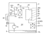
- FIG. 1 shows a lubrication system diagram of a power transmission device of a helicopter provided with a lubricating device LS according to a first embodiment of the present invention.
- the transmission 1 is provided with a transmission gear 4.
- the transmission gear 4 constitutes a rotating member of the transmission 1.
- the transmission gear 4 shifts the rotation of an engine (not shown) and transmits it to the main rotor (not shown) and the tail rotor (not shown).
- the lubrication target T of the lubrication device LS of the present embodiment is a rotating member of the transmission 1 of a helicopter.
- the lubrication target T is the transmission gear 4 and the bearing portion of the rotating shaft provided with the gear.
- the lubrication target T includes a first lubrication target 12 (FIG. 2) and a second lubrication target 14 (FIG. 2).
- the number of lubrication targets T is not limited to this.
- the second lubrication target 14 may be omitted. Further, the number of lubrication targets T may be three or more.
- the first lubrication target 12 rotates at a higher speed than the second lubrication target 14.
- the first lubrication target 12 be the portion of the transmission gear 4 that rotates at the highest speed.
- the first lubrication target 12 is preferably a gear to which rotation of an engine (not shown) is input, and its bearing.
- the lubricating device LS supplies lubricating oil OL to the lubrication target T.
- the lubricating device LS includes an oil sump 6, a lubricating pump 8, and a lubricating passage 10.
- the lubricating device LS includes a case 2 in which at least a part of the lubrication target T, the oil reservoir 26, and the lubricating passage 10 is accommodated.
- the oil sump 6 stores oil OL.
- the oil sump 6 is formed in the lower part of the case 2.
- the oil sump 6 is formed by denting a part (central part) of the bottom wall of the case 2 downward.
- the oil sump 6 is integrally formed with the case 2.
- the configuration of the oil sump 6 is not limited to this.
- a recess may be provided in a part of the side wall of the case 2 and the recess may be the oil sump 6.
- the lubrication pump 8 sucks and discharges the oil OL from the oil sump 6.
- the lubricating pump 8 is disposed in the oil sump 6.
- the lubricating pump 8 does not have to be disposed entirely in the oil sump 6, and a suction port or a pipe connected to the suction port may be disposed in the oil sump 6.
- the lubricating pump 8 is not particularly limited, and is, for example, a gear pump.
- the oil OL discharged from the lubricating pump 8 is supplied to the lubrication target T through the lubricating passage 10.
- the lubricating passage 10 is a passage of oil OL from the lubricating pump 8 to the first lubrication target 12.
- the lubrication passage 10 is provided with various devices in the middle thereof. Further, the lubricating passage 10 is mainly configured by piping.
- the lubricating passage 10 has a supply port 20, an oil reservoir 26, and an opening 28.
- the lubrication passage 10 further includes an oil filter 16 and an oil cooler 18.
- the oil filter 16 is disposed downstream of the lubricating pump 8 to filter the oil OL.
- the oil cooler 18 is disposed downstream of the oil filter 16 to cool the oil OL.
- the oil filter 16 and the oil cooler 18 may be omitted depending on the use conditions.
- the oil filter 16 and the oil cooler 18 are disposed outside the case 2. Specifically, a part of the lubricating passage 10 extending from the lubricating pump 8 penetrates the wall of the case 2 and extends outside the case 2. The oil filter 16 and the oil cooler 18 are provided at a portion of the lubrication passage 10 extending outside the case 2. The lubrication passage 10 extends outside the case 2 and then penetrates the wall of the case 2 to enter the inside of the case 2 to supply oil OL to the object T to be lubricated.
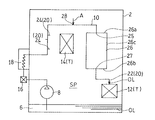
- FIG. 2 shows the lubrication system of FIG. 1 in a simplified manner.
- the supply port 20 supplies the oil OL to the lubrication target T.
- the supply port 20 is formed in the internal space SP of the case 2.
- the supply port 20 has a first supply port 22 for supplying the oil OL to the first lubrication target 12 and a second supply port 24 for supplying the oil OL to the second lubrication target 14.
- the number of supply ports 20 is not limited to this.
- the second lubrication target 14 is omitted, the second supply port 24 may be omitted.
- the supply ports 20 may be three or more.
- the first and second supply ports 22 and 24 are oil injection nozzles.
- the first and second supply ports 22 and 24 are not limited to this.
- the first and second supply ports 22 and 24 may be through holes formed in the pipe wall of the pipe constituting the lubrication passage 10.
- the first supply port 22 is disposed immediately above the first lubrication target 12.
- “disposed immediately above” means the oil OL, which is dropped above the first lubrication target 12 under the influence of gravity from the first supply port 22 during the dry run, to the first lubrication target 12. It means that the first supply port 22 is disposed within the reach range. That is, “directly on” includes a horizontal shift of the range in which the oil OL dropped by gravity reaches the first lubrication target 12. As described above, the first supply port 22 is configured to drop the oil OL onto the first lubrication target at the time of dry run.
- An oil reservoir 26 is provided upstream of the first supply port 22 in the lubrication passage 10. Specifically, an oil reservoir 26 is provided upstream of the first supply port 22 in the lubricating passage 10 and downstream of the second supply port 24. At normal times, the oil reservoir 26 holds the oil OL inside. At the time of dry run, the oil OL inside the oil reservoir 26 is dropped to the first lubrication target 12 via the first supply port 22.
- the volume of the oil reservoir 26 is appropriately set according to the required dry run capacity.
- the oil reservoir 26 is configured as a box-like tank. However, the configuration of the oil reservoir is not limited to this.
- the oil reservoir 26 may be formed by increasing the diameter of the pipe that constitutes the lubrication passage 10.
- the oil reservoir 26 is formed to have a larger passage area (cross-sectional area) than the pipes before and after it, and the storage amount of oil OL per unit length (the same length) is larger than that before and after the pipe It is formed large.
- the oil reservoir 26 may be provided integrally with the side wall or the upper wall of the case 2.
- the inlet 25 is formed in the upper wall 26 a of the box-like oil reservoir 26, and the outlet 27 is formed in the lower wall 26 b. That is, the lubricating passage 10 connected to the opening 28 is connected to the upper wall 26 a of the oil reservoir 26, and the lubricating passage 10 connected to the first supply port 22 is connected to the lower wall 26 b of the oil reservoir 26.
- the configuration of the oil reservoir is not limited to this.
- the outlet 27 of the oil reservoir 26 may be provided at the lower portion of the side wall 26c instead of the lower wall 26b.
- An opening 28 is provided upstream of the outlet 27 of the oil reservoir 26 in the lubricating passage 10 and above the outlet 27 of the oil reservoir 26.
- an opening 28 is provided on the upstream side of the oil reservoir 26 in the lubrication passage 10 and above the oil reservoir 26.
- the opening 28 may be located higher than the outlet 27 of the oil reservoir 26, and may be provided in the oil reservoir 26 itself. Even when the opening 28 is provided in the lubricating passage 10 upstream of the oil reservoir 26 as in the present embodiment, it is not necessary to be directly above the oil reservoir 26. That is, "upper” in this case means above (in the high position) in the vertical direction, and the oil reservoir 26 and the opening 28 may be arranged horizontally offset.
- the opening 28 is formed in the internal space SP of the case 2.
- the opening 28 is provided on the downstream side of the oil cooler 18 between the second supply port 24 and the oil reservoir 26.
- the opening 28 is normally configured to eject the oil OL. Therefore, if the lubrication target T is disposed downstream of the opening 28, the lubrication target T can be lubricated at normal times.
- the opening 28 Air is introduced into the lubricating passage 10.
- the opening 28 is a through hole provided in a pipe that constitutes the lubrication passage 10.
- the opening 28 is not limited to this.
- the opening 28 may be a hole of a projecting nozzle provided in a pipe. If the opening 28 is a nozzle, it is possible to accurately supply a part of the oil from the opening 28 to the lubrication target T at normal times.
- the opening 28 is disposed above at least the outlet 27 of the oil reservoir 26 and above the first supply port 22.
- the opening 28 is preferably disposed above the upper surface of the oil reservoir 26 (upper wall 26 a) or the upper surface of the oil reservoir 26.
- the lubrication passage 10 between the opening 28 and the oil reservoir 26 may be partially located above the opening 28.
- the oil OL in the portion located above the opening 28 in the lubricating passage 10 flows back and flows out from the opening 28.
- the lubricating passage 10 between the opening 28 and the oil reservoir 26 is preferably located below the opening 28.
- the first supply port 22 is disposed below at least the upper surface (upper wall 26 a) of the oil reservoir 26 and below the opening 28.
- the first supply port 22 is preferably disposed below the bottom surface (lower wall 26 b) of the oil reservoir 26. From the above, it is preferable that the opening 28 be disposed above the upper surface of the oil reservoir 26 or the upper surface of the oil reservoir 26, and the first supply port 22 be disposed below the bottom surface of the oil reservoir 26.
- FIG. 2 shows the flow of the oil OL at the normal time
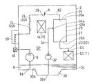
- FIG. 3 shows the flow of the oil OL at the dry run time.
- the oil OL in the oil sump 6 is sucked and discharged by the lubricating pump 8.
- the oil OL discharged from the lubricating pump 8 is supplied to the lubrication target T through the lubricating passage 10.
- the flow of the oil OL at the normal time in the present embodiment will be described in detail.
- the oil OL discharged by the lubricating pump 8 is filtered by the oil filter 16 outside the case 2 and then cooled by the oil cooler 18.
- the oil OL cooled by the oil cooler 18 is returned to the inside of the case 2 and a part thereof is supplied to the second lubrication target 14 from the second supply port 24.
- the oil OL is injected from the second supply port 24 in response to the oil pressure in the lubricating passage 10.
- the oil OL further flows in the lubricating passage 10 and a portion thereof is injected from the opening 28 into the internal space SP of the case 2.
- the remainder of the oil OL further flows in the lubricating passage 10 and reaches the oil reservoir 26.
- the oil reservoir 26 holds a predetermined amount of oil OL.
- the oil OL that has passed through the oil reservoir 26 is supplied from the first supply port 22 to the first lubrication target 12. Under normal conditions, the oil OL is injected from the first supply port 22 in response to the oil pressure in the lubricating passage 10.
- the oil OL supplied from the first and second supply ports 22 and 24 and the oil OL injected from the opening 28 are recovered in the oil sump 6 after lubricating the first lubrication target 12 and the second lubrication target 14 .
- the oil pressure P3 in the oil reservoir 26 is maintained in the same state as the pressure P2 of the oil sump 6 (internal space SP) through the opening 28, so that stable dripping lubrication is realized. At this time, since the pressure of the oil OL located upstream of the opening 28 of the lubricating passage 10 is reduced, the oil supply from the second supply port 24 to the second lubrication target 14 is stopped.
- the oil OL in the lubricating passage 10 is supplied to the first lubrication target 12 from the first supply port 22 via the oil reservoir 26 in the normal state of FIG. Also, at a normal time, the oil reservoir 26 holds a predetermined amount of oil OL.
- air A is taken into the lubricating passage 10 from the opening 28. Then, the oil OL in the oil reservoir 26 and the oil OL in the lubricating passage 10 between the opening 28 and the oil reservoir 26 are dropped from the first supply port 22 to the first lubrication target 12 under the influence of gravity. .
- the common oil reservoir 26 enables normal oil lubrication and dripping lubrication during dry running. Therefore, the dry run capability can be improved with a simple configuration.
- the oil sump 6, the lubrication pump 8, the lubrication target T, and the oil reservoir 26 are accommodated in the case 2, and an opening 28 is formed in the internal space SP of the case 2.
- the oil OL injected from the opening 28 can be supplied to the lubrication target T disposed in the internal space SP of the case 2.
- An opening 28 of the lubricating passage 10 is provided on the downstream side of an oil cooler 18 provided outside the case 2. Therefore, during normal times, the oil OL after cooling by the oil cooler 18 can be supplied to the first lubrication target 12, and from between the oil cooler 18 and the oil reservoir 26 in the lubrication passage 10 to the second lubrication target 14. The oil OL after cooling can be supplied.
- a second supply port 24 for supplying the oil OL to the second lubrication target 14 is provided on the upstream side of the oil reservoir 26 in the lubrication passage 10, and an opening 28 is provided between the second supply port 24 and the oil reservoir 26. ing. As a result, during the dry run, it is possible to effectively lubricate the first lubrication target 12 having a high degree of lubrication priority.
- the first lubrication target 12 and the second lubrication target 14 are rotation members of the transmission, and the high-speed rotation member rotating at a speed higher than that of the second lubrication target 14 is the first lubrication target 12. It is possible to intensively lubricate a high speed rotating member having a high priority of lubrication.
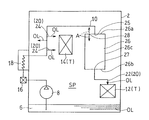
- FIG. 4 is a system diagram showing a lubricating system of a lubricating device according to a second embodiment of the present invention in a simplified manner.
- the lubricating device LS of the second embodiment differs from the first embodiment in that it includes an auxiliary oil sump 30, an auxiliary lubrication pump 32, and an auxiliary lubrication passage 34.
- the auxiliary oil sump 30 stores spare oil OL.
- the spare oil OL is supplied to the lubrication target T at the time of dry run.
- the auxiliary oil sump 30 of the present embodiment is formed below the bottom of the oil sump 6.
- the auxiliary oil sump 30 is composed of a recess formed in the bottom of the oil sump 6.
- the configuration of the auxiliary oil sump 30 is not limited to this.
- the suction port 8 a of the lubricating pump 8 is located above the upper edge 30 a (the same height as the bottom surface of the oil sump 6) of the recess 30 in the oil sump 6.
- the auxiliary lubrication pump 32 sucks and discharges the oil OL from the auxiliary oil sump 30.
- the suction port 32 a of the auxiliary lubrication pump 32 is located below the upper edge 30 a of the recess 30, that is, in the recess 30. Therefore, the upper edge 30 a of the recess 30 is located above the suction port 32 a of the auxiliary lubrication pump 32.
- the upper and lower portions herein refer to the upper and lower positions in the vertical direction, and the horizontal position does not matter.
- the auxiliary lubrication pump 32 may be a centrifugal centrifugal pump in order to suppress an increase in the hydraulic pressure P4 in the auxiliary lubrication passage 34.
- the auxiliary lubrication passage 34 connects the auxiliary lubrication pump 32 and the oil reservoir 26.
- the auxiliary lubrication passage 34 and the oil reservoir 26 are connected by the connection port 34 a.
- no oil filter is provided in the auxiliary lubrication passage 34.
- the oil pressure P1 in the lubrication passage 10 at the normal time is set larger than the oil pressure P4 in the auxiliary lubrication passage 34.
- the hydraulic pressure P4 in the auxiliary lubrication passage 34 is set to be larger than the pressure P2 of the oil sump 6 (the internal space SP).
- a relief valve may be provided in the auxiliary lubrication passage 34 in order to suppress an increase in the hydraulic pressure P4 in the auxiliary lubrication passage 34.
- the other configuration is the same as that of the first embodiment.
- the hydraulic pressure P1 in the lubricating passage 10 is larger than the pressure P2 of the oil sump 6 (internal space SP) and larger than the hydraulic pressure P4 in the auxiliary lubricating passage 34. That is, the discharge pressure of the lubrication pump 8 is larger than the discharge pressure of the auxiliary lubrication pump 32.
- the oil pressure P1 in the lubricating passage 10 is pushed to close the connection port 34a from the auxiliary lubricating passage 34 to the oil reservoir 26 so that oil is supplied to the oil reservoir 26. I can not do it. Therefore, the flow of the oil OL at the normal time is the same as that of the first embodiment described above.
- the auxiliary lubrication passage 34 is preferably configured to communicate with the oil reservoir 26 only during dry running.
- the oil OL is supplied from the auxiliary lubrication passage 34 to the oil reservoir 26 at the time of dry run, the oil circulation amount at the time of dry run can be increased. Therefore, the dry run ability can be further improved.
- the hydraulic pressure P1 in the lubricating passage 10 is set larger than the hydraulic pressure P4 in the auxiliary lubricating passage 34. That is, under normal conditions, the auxiliary lubricating passage 34 does not function due to the hydraulic pressure P1 of the lubricating passage 10. Therefore, it is not necessary to provide an oil filter in the auxiliary lubrication passage 34, and the number of parts can be reduced. In normal times, the clean oil OL that has passed through the oil filter 16 disposed downstream of the lubricating pump 8 is distributed to each part. The oil filter 16 contributes to prolonging the life of gears and bearings, but since the oil supply during dry run is extremely short, the omission of the oil filter has almost no influence on the life.
- the auxiliary oil sump 30 is formed of a recess formed in the bottom of the oil sump 6, the lubricating device LS can be made compact. By setting the depths of the oil sumps 6, 30 in two steps, it is easy to secure the oil OL at the dry run time.
- the auxiliary lubrication pump 32 can also reuse the oil OL recovered at the time of dry run.
- FIG. 5 is a system diagram showing a lubricating system of a lubricating device according to a third embodiment of the present invention in a simplified manner.
- the position of the opening 28 of the lubricating device LS of the third embodiment is different from that of the first embodiment.
- the opening 28 is formed in the upper surface (upper wall 26 a) of the oil reservoir 26.
- the opening 28 may be formed on the top of the side wall 26 c of the oil reservoir 26, preferably above 2/3 of the height of the oil reservoir 26.
- the other configuration is the same as that of the lubricating device LS of the first embodiment.
- one or more of the oil filter 16, the oil cooler 18, and the second supply port 24 may be omitted depending on the situation. Furthermore, the auxiliary oil sump 30, the auxiliary lubrication pump 32, and the auxiliary lubrication passage 34 of the second embodiment may be introduced into the lubricating device LS of the third embodiment.
- the oil reservoir 26 holds a predetermined amount of oil OL.
- the air A in the oil reservoir 26 is discharged from the opening 28 of the upper wall 26 a to the outside of the oil reservoir 26. Therefore, it is possible to prevent an air reservoir from being formed inside the oil reservoir 26. As a result, the volume of the oil reservoir 26 can be used effectively.
- the oil OL that has passed through the oil reservoir 26 is supplied from the first supply port 22 to the first lubrication target 12.
- the opening 28 is not limited to the through hole provided in the pipe that constitutes the lubricating passage 10, and may be a projecting nozzle.
- the oil OL can be supplied to the lubrication target T from the opening 28 at normal times. Therefore, such is also included in the scope of the present invention.
Landscapes
- Engineering & Computer Science (AREA)
- General Engineering & Computer Science (AREA)
- Mechanical Engineering (AREA)
- Aviation & Aerospace Engineering (AREA)
- General Details Of Gearings (AREA)
Abstract
潤滑装置(LS)は、潤滑用のオイル(OL)が貯留されたオイルサンプ(6)と、オイルサンプ(6)内のオイル(OL)を吸引して吐出する潤滑ポンプ(8)と、潤滑ポンプ(8)から第1潤滑対象(12)へ至る潤滑通路(10)とを備えている。潤滑通路(10)は、オイル(OL)を第1潤滑対象(12)に供給する第1供給口(22)と、第1供給口(22)の上流側に設けられたオイルリザーバ(26)と、オイルリザーバ(26)の上流側でオイルリザーバ(26)よりも上方に設けられた開口(28)とを有している。第1供給口(22)は、第1潤滑対象(12)の直上に形成されている。
Description
この出願は、2017年6月27日出願の特願2017-124891の優先権を主張するものであり、その全体を参照により本願の一部をなすものとして引用する。
本発明は、ヘリコプタ用の潤滑装置に関するものである。
ヘリコプタ用の動力伝達装置には、オイルが遮断された状態でも運行可能なドライラン能力が要求される。現状の技術でも必要なドライラン能力は確保されているが、洋上運行の増加などの昨今の動向から、さらなるドライラン能力の向上が望まれる。現状のドライラン対策として、非常用のオイルを備蓄して非常時に補給を継続するものがある(例えば、特許文献1)。
特許文献1では、潤滑装置が、通常時に用いる主潤滑系統とドライラン時に用いる補助潤滑系統とを備える。補助潤滑系統は、通常時に主潤滑系統からオイル分配を受けてタンクにオイルを貯留し、ドライラン時にタンクからオイルを少量ずつ放出する。しかしながら、特許文献1のように潤滑系統を二重化すると、構造が複雑となる。
そこで、本発明は、簡単な構成で、ドライラン能力の向上を図ることができる潤滑装置を提供することを目的とする。
上記目的を達成するために、本発明の潤滑装置は、潤滑用のオイルが貯留されたオイルサンプと、前記オイルサンプからオイルを吸引して吐出する潤滑ポンプと、前記潤滑ポンプから第1潤滑対象へ至る潤滑通路とを備えている。前記潤滑通路は、前記第1潤滑対象の直上に形成されて前記潤滑通路のオイルを前記第1潤滑対象に供給する第1供給口と、前記第1供給口の上流側に設けられたオイルリザーバと、前記オイルリザーバの出口よりも上流側で前記オイルリザーバの出口よりも上方に設けられた開口とを有している。
この構成によれば、通常時、潤滑通路のオイルは、オイルリザーバを介して第1供給口から第1潤滑対象に供給される。また、通常時に、オイルリザーバに所定量のオイルが保持される。潤滑通路に含まれるコネクタからのオイル漏れのような不具合により潤滑通路内の油圧が低下してドライラン状態となったときには、つまり、潤滑通路内の油圧がオイルサンプの油圧まで低下したときには、開口から潤滑通路内に空気が取り入れられる。そうすると、オイルリザーバ内のオイルを含む、開口よりも下流側の潤滑通路内のオイルが、重力の影響を受けて、第1供給口から直下の第1潤滑対象へ滴下される。このとき、オイルリザーバ内の油圧は、開口を介して潤滑装置のサンプ圧と同じ状態に保たれるので、安定した滴下潤滑が実現される。このように、共通のオイルリザーバで、通常時のオイル潤滑も、ドライラン時の滴下潤滑も可能となる。したがって、簡単な構成で、ドライラン能力の向上を図ることができる。
本発明において、さらに、少なくとも前記オイルサンプ、前記潤滑ポンプ、前記第1潤滑対象および前記オイルリザーバを収納するケースを備え、前記開口が前記ケースの内部空間に形成されていてもよい。この構成によれば、通常時は、開口からオイルを、ケースの内部空間に配置された別の潤滑対象に供給することができる。
本発明において、前記潤滑通路は、さらに、前記ケースの外側に設けられて前記潤滑通路内のオイルを冷却するオイルクーラを有し、前記開口が、前記潤滑通路における前記オイルクーラの下流側に設けられていてもよい。この構成によれば、オイルクーラまたはオイルクーラの接続部からオイル漏れが発生しても、オイルが第1供給口から直下の第1潤滑対象へ滴下される。したがって、ドライラン能力の向上を図ることができる。
本発明において、前記潤滑通路は、さらに、前記オイルリザーバの上流側に、前記潤滑通路のオイルを第2潤滑対象に供給する第2供給口を有していてもよい。この場合、前記第1潤滑対象および前記第2潤滑対象はトランスミッションの回転部材であり、前記第1潤滑対象が前記第2潤滑対象よりも高速で回転していてもよい。この構成によれば、ドライラン時に、特に潤滑要求の高い高速回転部材を重点的に潤滑することができる。
本発明において、前記開口は、前記潤滑通路における前記オイルリザーバの上流側で前記オイルリザーバよりも上方に設けられてもよい。この構成によれば、ドライラン時に、オイルリザーバの上流側で開口の下流側のオイルも滴下潤滑に利用することができる。この場合、前記開口は、前記第2供給口と前記オイルリザーバとの間に設けられていてもよい。この構成によれば、潤滑の優先度が低い部分を第2潤滑対象とすることにより、ドライラン時に、潤滑の優先度が高い第1潤滑対象を効果的に潤滑することができる。
本発明において、前記開口は、前記オイルリザーバに設けられてもよい。この場合、前記開口は、前記オイルリザーバの上壁に設けられてもよい。この構成によれば、潤滑装置の始動時に、オイルリザーバ内の空気を開口から効果的に排出できる。
本発明において、さらに、予備のオイルが貯留される補助オイルサンプと、前記補助オイルサンプからオイルを吸引して吐出する補助潤滑ポンプと、前記補助潤滑ポンプと前記オイルリザーバを接続する補助潤滑通路とを備えていてもよい。この構成によれば、補助オイルサンプを設けることにより、ドライラン時のオイル循環量を増やすことができる。
前記補助潤滑通路が設けられる場合、前記潤滑通路内の油圧が前記オイルサンプの油圧よりも大きいとき、つまり通常時、前記潤滑通路内の油圧が前記補助潤滑通路内の油圧よりも大きくてもよい。この構成によれば、通常時は、潤滑通路の油圧により、補助潤滑通路のオイルリザーバへの接続口が塞がれるので、補助潤滑通路は機能しない。したがって、通常時は補助潤滑通路にオイルが流れないので、補助潤滑通路にオイルフィルタを設ける必要がない。
前記補助オイルサンプが設けられる場合、前記補助オイルサンプは、前記オイルサンプの底部に形成される凹所であり、前記潤滑ポンプの吸引口は、前記オイルサンプ内における前記凹所よりも上方に位置し、前記補助潤滑ポンプの吸引口は、前記凹所内に位置していてもよい。この構成によれば、補助オイルサンプが、オイルサンプの底部に形成される凹所で構成されているので、潤滑装置をコンパクト化できる。
請求の範囲および/または明細書および/または図面に開示された少なくとも2つの構成のどのような組合せも、本発明に含まれる。特に、請求の範囲の各請求項の2つ以上のどのような組合せも、本発明に含まれる。
本発明は、添付の図面を参考にした以下の好適な実施形態の説明からより明瞭に理解されるであろう。しかしながら、実施形態および図面は単なる図示および説明のためのものであり、本発明の範囲を定めるために利用されるべきものではない。本発明の範囲は添付の請求の範囲によって定まる。添付図面において、複数の図面における同一の部品番号は、同一または相当部分を示す。
本発明の第1実施形態に係る潤滑装置の潤滑系統を示す系統図である。
同潤滑装置の潤滑系統を簡略化して示す系統図である。
同潤滑系統のドライラン時の状態を簡略化して示す系統図である。
本発明の第2実施形態に係る潤滑装置の潤滑系統を示す系統図である。
本発明の第3実施形態に係る潤滑装置の潤滑系統を示す系統図である。
以下、本発明の好ましい実施形態について図面を参照しながら説明する。以下の説明において、「通常時」とは、ヘリコプタの動力伝達装置(トランスミッション)において潤滑オイルが正常に供給、循環された状態で、ヘリコプタが運転している時をいう。「ドライラン時」とは、ヘリコプタの動力伝達装置に内包された潤滑オイルが漏れた状態で、ヘリコプタが運転している時をいう。
図1は、本発明の第1実施形態に係る潤滑装置LSを備えた、ヘリコプタの動力伝達装置の潤滑系統図を示す。トランスミッション1は、変速歯車4を備えている。変速歯車4は、トランスミッション1の回転部材を構成する。変速歯車4は、エンジン(図示せず)の回転を変速して、メインロータ(図示せず)およびテールロータ(図示せず)に伝達する。
本実施形態の潤滑装置LSの潤滑対象Tは、ヘリコプタのトランスミッション1の回転部材である。詳細には、潤滑対象Tは、変速歯車4や、歯車が設けられる回転軸体の軸受部である。特に、潤滑対象Tが変速歯車4である場合、その噛合い部にオイルOLを供給することが好ましい。潤滑対象Tは、第1潤滑対象12(図2)と、第2潤滑対象14(図2)とを有している。なお、潤滑対象Tの数は、これに限られない。例えば、第2潤滑対象14を省略してもよい。また、潤滑対象Tの数は、3つ以上であってもよい。本実施形態では、第1潤滑対象12は、第2潤滑対象14よりも高速で回転している。特に、第1潤滑対象12は、変速歯車4で最も高速で回転する部分であることが好ましい。例えば、第1潤滑対象12は、エンジン(図示せず)の回転が入力される歯車と、その軸受であることが好ましい。
潤滑装置LSは、潤滑対象Tに対して、潤滑用のオイルOLを供給する。潤滑装置LSは、オイルサンプ6と、潤滑ポンプ8と、潤滑通路10とを備えている。また、潤滑装置LSは、潤滑対象T、オイルリザーバ26、および潤滑通路10の少なくとも一部を収容するケース2を備えている。
オイルサンプ6は、オイルOLを貯留する。本実施形態では、オイルサンプ6は、ケース2の下部に形成されている。詳細には、オイルサンプ6は、ケース2の底壁の一部(中央部)を下方へ凹ませて形成されている。本実施形態では、オイルサンプ6は、ケース2と一体に形成されている。なお、オイルサンプ6の構成は、これに限定されない。例えば、ケース2の側壁の一部に窪みを設けて、その窪みをオイルサンプ6としてもよい。
潤滑ポンプ8は、オイルサンプ6からオイルOLを吸引して吐出する。潤滑ポンプ8は、オイルサンプ6内に配置されている。ただし、潤滑ポンプ8は、その全体がオイルサンプ6内に配置されている必要はなく、その吸込口または吸込口に接続される配管がオイルサンプ6内に配置されていればよい。潤滑ポンプ8は、特に限定されるものではないが、例えば、ギヤポンプである。潤滑ポンプ8から吐出されたオイルOLは、潤滑通路10を通って潤滑対象Tに供給される。
潤滑通路10は、潤滑ポンプ8から第1潤滑対象12へ至るオイルOLの通路である。潤滑通路10は、その途中に種々の機器が設けられている。また、潤滑通路10は、主として配管で構成されている。潤滑通路10は、供給口20と、オイルリザーバ26と、開口28とを有している。本実施形態では、潤滑通路10は、さらに、オイルフィルタ16と、オイルクーラ18とを有している。オイルフィルタ16は、潤滑ポンプ8の下流側に配置されてオイルOLを濾過する。オイルクーラ18は、オイルフィルタ16の下流側に配置されてオイルOLを冷却する。なお、使用条件によっては、オイルフィルタ16やオイルクーラ18を省略してもよい。
本実施形態では、オイルフィルタ16およびオイルクーラ18は、ケース2の外側に配置されている。具体的には、潤滑ポンプ8から延びる潤滑通路10は、その一部分がケース2の壁を貫通してケース2の外側を延びる。オイルフィルタ16およびオイルクーラ18は、潤滑通路10におけるケース2の外側を延びる部分に設けられている。潤滑通路10は、ケース2の外側を延びたあと、ケース2の壁を貫通してケース2の内部に入って潤滑対象TにオイルOLを供給する。
図2は、図1の潤滑系統を簡略化して示す。供給口20は、潤滑対象TにオイルOLを供給する。供給口20は、ケース2の内部空間SPに形成されている。本実施形態では、供給口20は、オイルOLを第1潤滑対象12に供給する第1供給口22と、オイルOLを第2潤滑対象14に供給する第2供給口24とを有している。なお、供給口20の数は、これに限らない。例えば、第2潤滑対象14を省略する場合には、第2供給口24を省略してもよい。また、潤滑対象Tの数が3つ以上である場合には、供給口20を3つ以上としてもよい。第1および第2供給口22,24は、オイル噴射ノズルである。ただし、第1および第2供給口22,24は、これに限定されない。例えば、第1および第2供給口22,24は、潤滑通路10を構成する配管の管壁に形成される貫通孔であってもよい。
第1供給口22は、第1潤滑対象12の直上に配置されている。ここで、「直上に配置される」とは、第1潤滑対象12の上方であって、ドライラン時に第1供給口22から重力の影響を受けて滴下されるオイルOLが第1潤滑対象12に到達する範囲に、第1供給口22が配置されることをいう。つまり、「直上」とは、重力により滴下されるオイルOLが第1潤滑対象12に到達する範囲の水平方向のずれを含む。このように、第1供給口22が、ドライラン時にオイルOLを第1潤滑対象に滴下するように構成されている。
潤滑通路10における第1供給口22の上流側に、オイルリザーバ26が設けられている。詳細には、潤滑通路10における第1供給口22の上流側で第2供給口24の下流側に、オイルリザーバ26が設けられている。通常時に、オイルリザーバ26は、内部にオイルOLを保持する。ドライラン時に、オイルリザーバ26の内部のオイルOLが、第1供給口22を介して第1潤滑対象12に滴下される。オイルリザーバ26の容量は、要求されるドライラン能力に応じて適宜設定される。本実施形態では、オイルリザーバ26は、箱状のタンクとして構成されている。ただし、オイルリザーバの構成は、これに限られない。例えば、オイルリザーバ26は、潤滑通路10を構成する配管を拡径して形成されていてもよい。このように、オイルリザーバ26は、その前後の配管よりも通路面積(断面積)が大きく形成され、単位長さ当たり(同一の長さ)のオイルOLの貯留量が、その前後の配管よりも大きく形成されている。また、オイルリザーバ26は、ケース2の側壁や上壁と一体に設けてもよい。
本実施形態では、箱状のオイルリザーバ26の上壁26aに入口25が形成され、下壁26bに出口27が形成されている。つまり、開口28に繋がる潤滑通路10がオイルリザーバ26の上壁26aに接続され、第1供給口22に繋がる潤滑通路10がオイルリザーバ26の下壁26bに接続されている。ただし、オイルリザーバの構成は、これに限定されない。例えば、オイルリザーバ26の出口27を、下壁26bではなく、側壁26cの下部に設けてもよい。
潤滑通路10におけるオイルリザーバ26の出口27よりも上流側でオイルリザーバ26の出口27よりも上方に、開口28が設けられている。本実施形態では、潤滑通路10におけるオイルリザーバ26の上流側でオイルリザーバ26よりも上方に、開口28が設けられている。開口28は、オイルリザーバ26の出口27よりも高い位置にあればよく、オイルリザーバ26自体に設けてもよい。本実施形態のように開口28がオイルリザーバ26よりも上流の潤滑通路10に設けられる場合でも、オイルリザーバ26の直上にある必要はない。すなわち、ここでの「上方」は、鉛直方向における上方(高い位置にあること)を意味し、オイルリザーバ26と開口28は水平方向にずれて配置されていてもよい。開口28は、ケース2の内部空間SPに形成されている。本実施形態では、開口28は、オイルクーラ18の下流側で、第2供給口24とオイルリザーバ26との間に設けられている。
開口28は、通常時、オイルOLを噴出するように構成されている。そのため、開口28の下流に潤滑対象Tを配置すれば、通常時に、その潤滑対象Tを潤滑することができる。一方で、開口28は、潤滑通路10内の油圧が低下したとき、具体的には、潤滑通路10内の油圧がオイルサンプ6(内部空間SP)の圧力まで低下したときに、この開口28から潤滑通路10内に空気が取り入れられるように構成されている。本実施形態では、開口28は、潤滑通路10を構成する配管に設けられた貫通孔である。ただし、開口28は、これに限定されない。例えば、開口28は、配管に設けられた突起状のノズルの孔であってもよい。開口28をノズルで構成すれば、通常時に、開口28から潤滑対象Tにオイルの一部を正確に供給することができる。
より詳細には、開口28は、オイルリザーバ26の少なくとも出口27よりも上方で、且つ、第1供給口22よりも上方に配置される。開口28は、オイルリザーバ26の上面(上壁26a)またはオイルリザーバ26の上面よりも上方に配置されることが好ましい。これにより、オイルリザーバ26に保持されたすべてのオイルOLを、ドライラン時に第1潤滑対象12に供給できる。開口28とオイルリザーバ26との間の潤滑通路10は、その一部が開口28よりも上方に位置していてもよい。ただし、この場合、ドライラン時に、潤滑通路10における開口28よりも上方に位置する部分のオイルOLが逆流して、開口28から流出する。したがって、開口28とオイルリザーバ26との間の潤滑通路10は、開口28よりも下方に配置されるのが好ましい。
第1供給口22は、オイルリザーバ26の少なくとも上面(上壁26a)よりも下方で、且つ、開口28よりも下方に配置される。ただし、第1供給口22がオイルリザーバ26の底面(下壁26b)よりも上方に配置されると、ドライラン時に、オイルリザーバ26における第1供給口22よりも下方に保持されたオイルOLが第1潤滑対象12に供給されない。したがって、第1供給口22は、オイルリザーバ26の底面(下壁26b)よりも下方に配置されることが好ましい。以上より、開口28が、オイルリザーバ26の上面またはオイルリザーバ26の上面よりも上方に配置され、第1供給口22がオイルリザーバ26の底面よりも下方に配置されることが好ましい。これにより、ドライラン時に、オイルリザーバ26のすべてのオイルOLを第1潤滑対象12に供給できる。
つぎに、図2、3を用いて、本実施形態の潤滑装置LSの動作を説明する。図2は通常時のオイルOLの流れを示し、図3はドライラン時のオイルOLの流れを示している。図2に示す通常時、オイルサンプ6内のオイルOLが、潤滑ポンプ8により吸引され吐出される。潤滑ポンプ8から吐出されたオイルOLは、潤滑通路10を通って潤滑対象Tに供給される。
本実施形態における、通常時のオイルOLの流れを詳細に述べる。潤滑ポンプ8により吐出されたオイルOLは、ケース2の外部のオイルフィルタ16でろ過された後、オイルクーラ18で冷却される。オイルクーラ18で冷却されたオイルOLは、ケース2の内部に戻され、その一部が第2供給口24から第2潤滑対象14に供給される。なお、通常時には、オイルOLは、潤滑通路10内の油圧を受けて、第2供給口24から噴射される。
オイルOLは、さらに、潤滑通路10内を流れて、その一部が開口28からケース2の内部空間SPに噴射される。オイルOLの残部は、潤滑通路10内をさらに流れ、オイルリザーバ26に到達する。ここでは、オイルリザーバ26に所定量のオイルOLが保持される。オイルリザーバ26を通過したオイルOLは、第1供給口22から第1潤滑対象12に供給される。なお、通常時には、オイルOLは、潤滑通路10内の油圧を受けて、第1供給口22から噴射される。第1および第2供給口22,24から供給されたオイルOLと、開口28から噴射されたオイルOLは、第1潤滑対象12および第2潤滑対象14を潤滑したのちオイルサンプ6に回収される。
オイル漏れ等に起因する図3のドライラン時、オイルの供給が止まる。そうすると、潤滑通路10内の油圧P1が低下する。潤滑通路10内の油圧P1がオイルサンプ6(内部空間SP)の圧力P2まで低下すると、開口28から潤滑通路10内に空気Aが取り入れられる。これにより、潤滑通路10の開口28よりも下流側にあるオイルOLは、重力の影響を受けて、オイルリザーバ26内に入る。また、オイルリザーバ26内のオイルOLは、重力の影響を受けて、第1供給口22から第1潤滑対象12に滴下される。オイルリザーバ26内の油圧P3は、開口28を介してオイルサンプ6(内部空間SP)の圧力P2と同じ状態に保たれるので、安定した滴下潤滑が実現される。このとき、潤滑通路10の開口28よりも上流側にあるオイルOLは圧力が低下しているので、第2供給口24から第2潤滑対象14へのオイル供給は停止される。
上記構成によれば、図2の通常時、潤滑通路10のオイルOLは、オイルリザーバ26を介して第1供給口22から第1潤滑対象12に供給される。また、通常時に、オイルリザーバ26に所定量のオイルOLが保持される。図3のドライラン時、開口28から潤滑通路10内に空気Aが取り入れられる。そうすると、オイルリザーバ26内のオイルOLおよび開口28とオイルリザーバ26の間の潤滑通路10内のオイルOLが、重力の影響を受けて、第1供給口22から第1潤滑対象12に滴下される。このように、共通のオイルリザーバ26で、通常時のオイル潤滑も、ドライラン時の滴下潤滑も可能となる。したがって、簡単な構成で、ドライラン能力の向上を図ることができる。
また、オイルサンプ6、潤滑ポンプ8、潤滑対象Tおよびオイルリザーバ26が、ケース2に収納され、開口28がケース2の内部空間SPに形成されている。これにより、図2の通常時は、開口28から噴射されるオイルOLにより、ケース2の内部空間SPに配置された潤滑対象Tに供給することができる。
潤滑通路10の開口28が、ケース2の外側に設けられたオイルクーラ18の下流側に設けられている。したがって、通常時、オイルクーラ18で冷却後のオイルOLを第1潤滑対象12に供給することができるほか、潤滑通路10におけるオイルクーラ18とオイルリザーバ26との間から、第2潤滑対象14に冷却後のオイルOLを供給することができる。
潤滑通路10におけるオイルリザーバ26の上流側に、第2潤滑対象14にオイルOLを供給する第2供給口24が設けられ、開口28が第2供給口24とオイルリザーバ26との間に設けられている。これにより、ドライラン時に、潤滑の優先度が高い第1潤滑対象12を効果的に潤滑することができる。
第1潤滑対象12および第2潤滑対象14がトランスミッションの回転部材であり、第2潤滑対象14よりも高速で回転している高速回転部材を第1潤滑対象12とすることで、ドライラン時に、特に潤滑の優先度が高い高速回転部材を重点的に潤滑することができる。
図4は、本発明の第2実施形態に係る潤滑装置の潤滑系統を簡略化して示す系統図である。第2実施形態の潤滑装置LSは、補助オイルサンプ30と、補助潤滑ポンプ32と、補助潤滑通路34とを備える点で、第1実施形態と相違している。
補助オイルサンプ30は、予備のオイルOLを貯留する。この予備のオイルOLは、ドライラン時に、潤滑対象Tに供給される。本実施形態の補助オイルサンプ30は、オイルサンプ6の底部より下方に形成されている。詳細には、補助オイルサンプ30は、オイルサンプ6の底部に形成される凹所で構成されている。ただし、補助オイルサンプ30の構成は、これに限定されない。潤滑ポンプ8の吸引口8aは、オイルサンプ6内における凹所30の上縁30a(オイルサンプ6の底面と同じ高さ)よりも上方に位置している。
補助潤滑ポンプ32は、補助オイルサンプ30からオイルOLを吸引して吐出する。補助潤滑ポンプ32の吸引口32aは、凹所30の上縁30aよりも下方、すなわち凹所30内に位置している。したがって、凹所30の上縁30aは、補助潤滑ポンプ32の吸引口32aよりも上方に位置する。ここでの上方および下方は、鉛直方向における上方および下方の位置を指すものであり、水平方向の位置は問わない。なお、補助潤滑ポンプ32は、補助潤滑通路34内の油圧P4の上昇を抑制するために、遠心渦巻きポンプであってもよい。
補助潤滑通路34は、補助潤滑ポンプ32とオイルリザーバ26とを接続する。補助潤滑通路34とオイルリザーバ26とは、接続口34aで接続される。第2実施形態では、補助潤滑通路34にオイルフィルタは設けられていない。通常時の潤滑通路10内の油圧P1は、補助潤滑通路34内の油圧P4よりも大きく設定されている。また、補助潤滑通路34内の油圧P4は、オイルサンプ6(内部空間SP)の圧力P2よりも大きく設定されている。なお、補助潤滑通路34内の油圧P4の上昇を抑制するために、補助潤滑通路34に、リリーフ弁を設けてもよい。その他の構成は、第1実施形態と同じである。
第2実施形態の潤滑装置の動作を説明する。通常時、潤滑通路10内の油圧P1がオイルサンプ6(内部空間SP)の圧力P2よりも大きく、補助潤滑通路34内の油圧P4よりも大きい。つまり、潤滑ポンプ8の吐出圧は、補助潤滑ポンプ32の吐出圧よりも大きい。これにより、通常時は、潤滑通路10内の油圧P1に押されて、補助潤滑通路34からオイルリザーバ26への接続口34aが塞がれる形となって、オイルリザーバ26へのオイル供給は行われない。したがって、通常時のオイルOLの流れは、上述の第1実施形態と同じである。
ドライラン時、上述の第1実施形態と同様に、潤滑通路10内の油圧P1がオイルサンプ6(内部空間SP)の圧力P2まで低下すると、開口28から潤滑通路10内に空気Aが取り入れられ、オイルリザーバ26内のオイルOLが第1潤滑対象12に滴下される。このとき、オイルリザーバ26内の油圧P3は、開口28を介してオイルサンプ6(内部空間SP)の圧力P2と同じ状態に保たれる。つまり、補助潤滑通路34内の油圧P4がオイルリザーバ26内の油圧P3よりも大きくなる。したがって、補助潤滑通路34からオイルリザーバ26へオイルOLが供給される。このように、補助潤滑通路34は、ドライラン時にのみオイルリザーバ26に連通するように構成されていることが好ましい。
第2実施形態によれば、ドライラン時に補助潤滑通路34からオイルリザーバ26へオイルOLが供給されるので、ドライラン時のオイル循環量を増やすことができる。したがって、さらなるドライラン能力の向上を図ることができる。
また、通常時には、潤滑通路10内の油圧P1が補助潤滑通路34内の油圧P4よりも大きく設定されている。つまり、通常時は、潤滑通路10の油圧P1により、補助潤滑通路34は機能しない。したがって、補助潤滑通路34に、オイルフィルタを設ける必要がなく、部品点数を減らすことができる。通常時は、潤滑ポンプ8の下流側に配置したオイルフィルタ16を通過した清浄なオイルOLが各部に分配される。オイルフィルタ16は、歯車や軸受の寿命延長に貢献するが、ドライラン時のオイル供給は極めて短時間であるから、オイルフィルタを省略しても、寿命にほとんど影響しない。
補助オイルサンプ30が、オイルサンプ6の底部に形成される凹所で構成されているので、潤滑装置LSをコンパクト化できる。オイルサンプ6,30の深さを2段階とすることで、ドライラン時のオイルOLを確保し易い。また、補助潤滑ポンプ32により、ドライラン時に回収されたオイルOLの再利用を図ることもできる。
図5は、本発明の第3実施形態に係る潤滑装置の潤滑系統を簡略化して示す系統図である。第3実施形態の潤滑装置LSは、開口28の位置が第1実施形態と相違している。具体的には、第3実施形態では、開口28は、オイルリザーバ26の上面(上壁26a)に形成されている。ただし、開口28は、オイルリザーバ26の側壁26cの上部、好ましくは、オイルリザーバ26の高さの2/3よりも上方に形成されてもよい。その他の構成は、第1実施形態の潤滑装置LSと同じである。
また、第3実施形態でも、第1実施形態と同様に、状況に応じて、オイルフィルタ16、オイルクーラ18および第2供給口24の一つまたは複数を省略してもよい。さらに、第3実施形態の潤滑装置LSに、第2実施形態の補助オイルサンプ30、補助潤滑ポンプ32および補助潤滑通路34を導入してもよい。
通常時、第1実施形態と同様に、オイルリザーバ26に所定量のオイルOLが保持される。このとき、図5に破線で示すように、オイルリザーバ26内の空気Aが、上壁26aの開口28からオイルリザーバ26の外部に排出される。したがって、オイルリザーバ26の内部に空気溜まりが形成されるのを防ぐことができる。その結果、オイルリザーバ26の容積を有効に活用することができる。オイルリザーバ26を通過したオイルOLは、第1供給口22から第1潤滑対象12に供給される。
ドライラン時、上述の第1実施形態と同様に、潤滑通路10内の油圧P1がオイルサンプ6(内部空間SP)の圧力P2まで低下すると、開口28からオイルリザーバ26内に空気Aが取り入れられ、オイルリザーバ26内のオイルOLが第1潤滑対象12に滴下される。オイルリザーバ26内の油圧P3は、開口28を介してオイルサンプ6(内部空間SP)の圧力P2と同じ状態に保たれるので、安定した滴下潤滑が実現される。
本発明は、以上の実施形態に限定されるものでなく、本発明の要旨を逸脱しない範囲内で、種々の追加、変更または削除が可能である。例えば、開口28は、潤滑通路10を構成する配管に設けられた貫通孔に限定されず、突起状のノズルであってもよい。この場合、通常時に、開口28からオイルOLを潤滑対象Tに供給することができる。したがって、そのようなものも本発明の範囲内に含まれる。
1 トランスミッション
2 ケース
6 オイルサンプ
8 潤滑ポンプ
10 潤滑通路
12 第1潤滑対象
14 第2潤滑対象
18 オイルクーラ
22 第1供給口
24 第2供給口
25 オイルリザーバの入口
26 オイルリザーバ
26a オイルリザーバの上壁
27 オイルリザーバの出口
28 開口
30 補助オイルサンプ(凹所)
32 補助潤滑ポンプ
34 補助潤滑通路
LS 潤滑装置
OL オイル
SP ケースの内部空間
2 ケース
6 オイルサンプ
8 潤滑ポンプ
10 潤滑通路
12 第1潤滑対象
14 第2潤滑対象
18 オイルクーラ
22 第1供給口
24 第2供給口
25 オイルリザーバの入口
26 オイルリザーバ
26a オイルリザーバの上壁
27 オイルリザーバの出口
28 開口
30 補助オイルサンプ(凹所)
32 補助潤滑ポンプ
34 補助潤滑通路
LS 潤滑装置
OL オイル
SP ケースの内部空間
Claims (12)
- 潤滑用のオイルが貯留されたオイルサンプと、
前記オイルサンプからオイルを吸引して吐出する潤滑ポンプと、
前記潤滑ポンプから第1潤滑対象へ至る潤滑通路と、を備え、
前記潤滑通路は、
前記第1潤滑対象の直上に形成されて、前記潤滑通路のオイルを前記第1潤滑対象に供給する第1供給口と、
前記第1供給口の上流側に設けられたオイルリザーバと、
前記オイルリザーバの出口よりも上流側で、前記オイルリザーバの出口よりも上方に設けられた開口と、を有しているヘリコプタ用の潤滑装置。 - 請求項1に記載の潤滑装置において、さらに、少なくとも前記オイルサンプ、前記潤滑ポンプ、前記第1潤滑対象および前記オイルリザーバを収納するケースを備え、
前記開口が、前記ケースの内部空間に形成されているヘリコプタ用の潤滑装置。 - 請求項2に記載の潤滑装置において、前記潤滑通路は、さらに、前記ケースの外側に設けられて前記潤滑通路内のオイルを冷却するオイルクーラを有し、
前記開口が、前記潤滑通路における前記オイルクーラの下流側に設けられているヘリコプタ用の潤滑装置。 - 請求項1から3のいずれか一項に記載の潤滑装置において、前記潤滑通路は、さらに、前記オイルリザーバの上流側に、前記潤滑通路のオイルを第2潤滑対象に供給する第2供給口を有しているヘリコプタ用の潤滑装置。
- 請求項4に記載の潤滑装置において、前記第1潤滑対象および前記第2潤滑対象は、トランスミッションの回転部材であり、
前記第1潤滑対象が、前記第2潤滑対象よりも高速で回転しているヘリコプタ用の潤滑装置。 - 請求項1から5のいずれか一項に記載の潤滑装置において、前記開口が、前記潤滑通路における前記オイルリザーバの上流側で、前記オイルリザーバよりも上方に設けられているヘリコプタ用の潤滑装置。
- 請求項4を引用する請求項6に記載の潤滑装置において、前記開口は、前記第2供給口と前記オイルリザーバとの間に設けられているヘリコプタ用の潤滑装置。
- 請求項1から5のいずれか一項に記載の潤滑装置において、前記開口が、前記オイルリザーバに設けられているヘリコプタ用の潤滑装置。
- 請求項8に記載の潤滑装置において、前記開口が、前記オイルリザーバの上壁に設けられているヘリコプタ用の潤滑装置。
- 請求項1から9のいずれか一項に記載の潤滑装置において、さらに、予備のオイルが貯留される補助オイルサンプと、
前記補助オイルサンプからオイルを吸引して吐出する補助潤滑ポンプと、
前記補助潤滑ポンプと前記オイルリザーバを接続する補助潤滑通路と、を備えたヘリコプタ用の潤滑装置。 - 請求項10に記載の潤滑装置において、前記潤滑通路内の油圧が前記オイルサンプの油圧よりも大きいとき、前記潤滑通路内の油圧が前記補助潤滑通路内の油圧よりも大きいヘリコプタ用の潤滑装置。
- 請求項10または11に記載の潤滑装置において、前記補助オイルサンプは、前記オイルサンプの底部に形成される凹所であり、
前記潤滑ポンプの吸引口は、前記オイルサンプ内における前記凹所よりも上方に位置し、
前記補助潤滑ポンプの吸引口は、前記凹所内に位置しているヘリコプタ用の潤滑装置。
Priority Applications (3)
| Application Number | Priority Date | Filing Date | Title |
|---|---|---|---|
| EP18822926.4A EP3647189B1 (en) | 2017-06-27 | 2018-06-26 | Lubrication device for helicopter |
| US16/722,373 US11365800B2 (en) | 2017-06-27 | 2019-12-20 | Lubrication device for helicopter |
| US17/824,579 US11965591B2 (en) | 2017-06-27 | 2022-05-25 | Lubrication device for helicopter |
Applications Claiming Priority (2)
| Application Number | Priority Date | Filing Date | Title |
|---|---|---|---|
| JP2017124891A JP6929143B2 (ja) | 2017-06-27 | 2017-06-27 | ヘリコプタ用の潤滑装置 |
| JP2017-124891 | 2017-06-27 |
Related Child Applications (1)
| Application Number | Title | Priority Date | Filing Date |
|---|---|---|---|
| US16/722,373 Continuation US11365800B2 (en) | 2017-06-27 | 2019-12-20 | Lubrication device for helicopter |
Publications (1)
| Publication Number | Publication Date |
|---|---|
| WO2019004177A1 true WO2019004177A1 (ja) | 2019-01-03 |
Family
ID=64741606
Family Applications (1)
| Application Number | Title | Priority Date | Filing Date |
|---|---|---|---|
| PCT/JP2018/024131 WO2019004177A1 (ja) | 2017-06-27 | 2018-06-26 | ヘリコプタ用の潤滑装置 |
Country Status (4)
| Country | Link |
|---|---|
| US (2) | US11365800B2 (ja) |
| EP (1) | EP3647189B1 (ja) |
| JP (1) | JP6929143B2 (ja) |
| WO (1) | WO2019004177A1 (ja) |
Families Citing this family (3)
| Publication number | Priority date | Publication date | Assignee | Title |
|---|---|---|---|---|
| US11209079B2 (en) * | 2018-05-01 | 2021-12-28 | Textron Innovations Inc. | Bypass block for unregulated gearboxes |
| GB201816504D0 (en) * | 2018-10-10 | 2018-11-28 | Rolls Royce Plc | Lubrication system |
| JP6996474B2 (ja) * | 2018-10-31 | 2022-01-17 | トヨタ自動車株式会社 | 動力伝達装置の潤滑装置 |
Citations (4)
| Publication number | Priority date | Publication date | Assignee | Title |
|---|---|---|---|---|
| US5121815A (en) * | 1990-02-20 | 1992-06-16 | Aerospatiale Societe Nationale Industrielle | Emergency lubricating device for a reduction unit particularly for a main gear box of a rotary-wing aircraft |
| JPH07217725A (ja) * | 1994-02-04 | 1995-08-15 | Toyota Motor Corp | 差動装置の潤滑構造 |
| US20160369887A1 (en) * | 2015-06-19 | 2016-12-22 | Sikorsky Aircraft Corporation | Lubrication systems for gearbox assemblies |
| US20170175875A1 (en) * | 2015-12-17 | 2017-06-22 | Airbus Helicopters | Emergency lubrication device of simplified architecture for a power transmission main gearbox of an aircraft |
Family Cites Families (21)
| Publication number | Priority date | Publication date | Assignee | Title |
|---|---|---|---|---|
| FR1194993A (fr) * | 1958-04-22 | 1959-11-13 | Cie Int Machines Agricoles | Dispositif de lubrification par aspersion en circuit fermé des transmissions par engrenages |
| DE2042206A1 (de) * | 1970-08-26 | 1972-03-02 | Porsche Kg | Schmiervorrichtung fuer Geschwindigkeitswechselgetriebe |
| DE3209514C2 (de) * | 1982-03-16 | 1984-04-26 | BHS-Bayerische Berg-, Hütten- und Salzwerke AG, 8000 München | In sich geschlossene Getriebeanlage mit Druckschmierung |
| DE3516710A1 (de) * | 1985-05-09 | 1986-11-13 | Robert Bosch Gmbh, 7000 Stuttgart | Behaelteranordnung fuer fahrzeuge mit gemeinsamen oelhaushalt |
| US4922765A (en) * | 1985-07-25 | 1990-05-08 | Aisin-Warner Kabushiki Kaisha | Lubricating structure for transmission mechanism |
| IT1232583B (it) * | 1989-02-14 | 1992-02-26 | Fiat Aviazione | Impianto di lubrificazione di organi meccanici particolarmente di impigo aeronautico provvisto di un dispositivo di emergenza atto a garantire una fornitura minima di olio lubrificante |
| JP3322072B2 (ja) * | 1994-08-12 | 2002-09-09 | トヨタ自動車株式会社 | 動力伝達機構の潤滑装置 |
| DE10206019A1 (de) * | 2002-02-14 | 2003-08-28 | Zahnradfabrik Friedrichshafen | Getriebe |
| ATE390349T1 (de) | 2005-06-30 | 2008-04-15 | Agusta Spa | Hubschrauber mit hilfschmierölkreislauf |
| US8602166B2 (en) * | 2006-01-05 | 2013-12-10 | Sikorsky Aircraft Corporation | Secondary lubrication system with injectable additive |
| ES2396138T3 (es) * | 2008-06-02 | 2013-02-19 | Vestas Wind Systems A/S | Un sistema de lubricación para un sistema de engranajes para una turbina eólica |
| US8646313B2 (en) * | 2009-06-22 | 2014-02-11 | Ford Global Technologies, Llc | System and method to provide lubrication for a plug-in hybrid |
| EP2672165B1 (en) * | 2009-11-16 | 2014-08-13 | Bell Helicopter Textron Inc. | Emergency subsystem for a fluid system |
| US9970527B2 (en) * | 2013-06-27 | 2018-05-15 | Eaton Corporation | Transmission lubrication system and apparatus |
| WO2015157271A1 (en) * | 2014-04-07 | 2015-10-15 | Eaton Corporation | Multi-component fluid distribution system |
| US10746284B2 (en) * | 2015-04-21 | 2020-08-18 | Sikorsky Aircraft Corporation | Gearbox lubrication system for aircraft |
| FR3037355B1 (fr) * | 2015-06-11 | 2017-05-19 | Airbus Helicopters | Boite de transmission de puissance et aeronef |
| US10145276B2 (en) * | 2015-06-23 | 2018-12-04 | United Technologies Corporation | Lubricant valve monitoring method and assembly |
| JP6809393B2 (ja) * | 2017-06-20 | 2021-01-06 | トヨタ自動車株式会社 | 車両用動力伝達装置の潤滑装置 |
| US10697586B2 (en) * | 2017-08-23 | 2020-06-30 | Bell Helicopter Textron Inc. | Supplemental lubrication pressurized by component or reservoir rotation |
| JP7111006B2 (ja) * | 2019-01-25 | 2022-08-02 | トヨタ自動車株式会社 | 車両用動力伝達装置 |
-
2017
- 2017-06-27 JP JP2017124891A patent/JP6929143B2/ja active Active
-
2018
- 2018-06-26 WO PCT/JP2018/024131 patent/WO2019004177A1/ja unknown
- 2018-06-26 EP EP18822926.4A patent/EP3647189B1/en active Active
-
2019
- 2019-12-20 US US16/722,373 patent/US11365800B2/en active Active
-
2022
- 2022-05-25 US US17/824,579 patent/US11965591B2/en active Active
Patent Citations (4)
| Publication number | Priority date | Publication date | Assignee | Title |
|---|---|---|---|---|
| US5121815A (en) * | 1990-02-20 | 1992-06-16 | Aerospatiale Societe Nationale Industrielle | Emergency lubricating device for a reduction unit particularly for a main gear box of a rotary-wing aircraft |
| JPH07217725A (ja) * | 1994-02-04 | 1995-08-15 | Toyota Motor Corp | 差動装置の潤滑構造 |
| US20160369887A1 (en) * | 2015-06-19 | 2016-12-22 | Sikorsky Aircraft Corporation | Lubrication systems for gearbox assemblies |
| US20170175875A1 (en) * | 2015-12-17 | 2017-06-22 | Airbus Helicopters | Emergency lubrication device of simplified architecture for a power transmission main gearbox of an aircraft |
Non-Patent Citations (1)
| Title |
|---|
| See also references of EP3647189A4 * |
Also Published As
| Publication number | Publication date |
|---|---|
| US20200124162A1 (en) | 2020-04-23 |
| EP3647189A4 (en) | 2021-03-31 |
| EP3647189B1 (en) | 2023-05-03 |
| JP2019006291A (ja) | 2019-01-17 |
| US11965591B2 (en) | 2024-04-23 |
| EP3647189A1 (en) | 2020-05-06 |
| US20220282782A1 (en) | 2022-09-08 |
| JP6929143B2 (ja) | 2021-09-01 |
| US11365800B2 (en) | 2022-06-21 |
Similar Documents
| Publication | Publication Date | Title |
|---|---|---|
| US11965591B2 (en) | Lubrication device for helicopter | |
| JP4880382B2 (ja) | 予備潤滑回路を備えたヘリコプタ | |
| JP4139797B2 (ja) | 潤滑装置および潤滑方法 | |
| US20230137698A1 (en) | Power transmission device for helicopter | |
| WO2020059786A1 (ja) | ヘリコプターのトランスミッション潤滑構造 | |
| EP0801594B1 (en) | Fluid circulation centrifugal cleaner | |
| JP2005220900A (ja) | 「戻り」型オイル供給・排出システム | |
| JP2013029121A (ja) | 変速機用油圧回路 | |
| JP5950870B2 (ja) | 油冷式スクリュ圧縮機 | |
| JP4973167B2 (ja) | コイル冷却装置 | |
| KR20200099476A (ko) | 건식 섬프를 구비한 냉각 윤활 시스템 | |
| KR20220044404A (ko) | 예비 탱크를 갖는 윤활 시스템 | |
| US3786901A (en) | Sealed lubricating system module | |
| JP7112922B2 (ja) | ヘリコプターのトランスミッション潤滑構造 | |
| IT201800003467A1 (it) | Gruppo di trasmissione con rotismo ordinario e asse di uscita verticale. | |
| JP2019011759A (ja) | チャンバ型オイル分配空間を有する排気タービン過給機 | |
| CN107407160A (zh) | 液体动压轴承 | |
| JP5116703B2 (ja) | スクリュー圧縮機 | |
| JP7278248B2 (ja) | トランスアクスル | |
| CN110630562A (zh) | 压缩机端盖及具有其的压缩机 | |
| JP5937130B2 (ja) | 油供給システム | |
| JP2023003579A (ja) | オイル潤滑装置 | |
| JP2020133604A (ja) | 遠心圧縮機 | |
| GB2385388A (en) | Oil system having a preferential fluid supply inlet |
Legal Events
| Date | Code | Title | Description |
|---|---|---|---|
| 121 | Ep: the epo has been informed by wipo that ep was designated in this application |
Ref document number: 18822926 Country of ref document: EP Kind code of ref document: A1 |
|
| NENP | Non-entry into the national phase |
Ref country code: DE |
|
| ENP | Entry into the national phase |
Ref document number: 2018822926 Country of ref document: EP Effective date: 20200127 |