WO2018235779A1 - ショベル - Google Patents
ショベル Download PDFInfo
- Publication number
- WO2018235779A1 WO2018235779A1 PCT/JP2018/023151 JP2018023151W WO2018235779A1 WO 2018235779 A1 WO2018235779 A1 WO 2018235779A1 JP 2018023151 W JP2018023151 W JP 2018023151W WO 2018235779 A1 WO2018235779 A1 WO 2018235779A1
- Authority
- WO
- WIPO (PCT)
- Prior art keywords
- shovel
- hydraulic
- boom
- pressure
- attachment
- Prior art date
Links
Images


Classifications
-
- E—FIXED CONSTRUCTIONS
- E02—HYDRAULIC ENGINEERING; FOUNDATIONS; SOIL SHIFTING
- E02F—DREDGING; SOIL-SHIFTING
- E02F3/00—Dredgers; Soil-shifting machines
- E02F3/04—Dredgers; Soil-shifting machines mechanically-driven
- E02F3/28—Dredgers; Soil-shifting machines mechanically-driven with digging tools mounted on a dipper- or bucket-arm, i.e. there is either one arm or a pair of arms, e.g. dippers, buckets
- E02F3/36—Component parts
- E02F3/42—Drives for dippers, buckets, dipper-arms or bucket-arms
- E02F3/43—Control of dipper or bucket position; Control of sequence of drive operations
- E02F3/435—Control of dipper or bucket position; Control of sequence of drive operations for dipper-arms, backhoes or the like
-
- E—FIXED CONSTRUCTIONS
- E02—HYDRAULIC ENGINEERING; FOUNDATIONS; SOIL SHIFTING
- E02F—DREDGING; SOIL-SHIFTING
- E02F3/00—Dredgers; Soil-shifting machines
- E02F3/04—Dredgers; Soil-shifting machines mechanically-driven
- E02F3/28—Dredgers; Soil-shifting machines mechanically-driven with digging tools mounted on a dipper- or bucket-arm, i.e. there is either one arm or a pair of arms, e.g. dippers, buckets
- E02F3/30—Dredgers; Soil-shifting machines mechanically-driven with digging tools mounted on a dipper- or bucket-arm, i.e. there is either one arm or a pair of arms, e.g. dippers, buckets with a dipper-arm pivoted on a cantilever beam, i.e. boom
- E02F3/32—Dredgers; Soil-shifting machines mechanically-driven with digging tools mounted on a dipper- or bucket-arm, i.e. there is either one arm or a pair of arms, e.g. dippers, buckets with a dipper-arm pivoted on a cantilever beam, i.e. boom working downwardly and towards the machine, e.g. with backhoes
-
- E—FIXED CONSTRUCTIONS
- E02—HYDRAULIC ENGINEERING; FOUNDATIONS; SOIL SHIFTING
- E02F—DREDGING; SOIL-SHIFTING
- E02F9/00—Component parts of dredgers or soil-shifting machines, not restricted to one of the kinds covered by groups E02F3/00 - E02F7/00
- E02F9/08—Superstructures; Supports for superstructures
- E02F9/10—Supports for movable superstructures mounted on travelling or walking gears or on other superstructures
- E02F9/12—Slewing or traversing gears
- E02F9/121—Turntables, i.e. structure rotatable about 360°
- E02F9/123—Drives or control devices specially adapted therefor
-
- E—FIXED CONSTRUCTIONS
- E02—HYDRAULIC ENGINEERING; FOUNDATIONS; SOIL SHIFTING
- E02F—DREDGING; SOIL-SHIFTING
- E02F9/00—Component parts of dredgers or soil-shifting machines, not restricted to one of the kinds covered by groups E02F3/00 - E02F7/00
- E02F9/20—Drives; Control devices
- E02F9/2004—Control mechanisms, e.g. control levers
-
- E—FIXED CONSTRUCTIONS
- E02—HYDRAULIC ENGINEERING; FOUNDATIONS; SOIL SHIFTING
- E02F—DREDGING; SOIL-SHIFTING
- E02F9/00—Component parts of dredgers or soil-shifting machines, not restricted to one of the kinds covered by groups E02F3/00 - E02F7/00
- E02F9/20—Drives; Control devices
- E02F9/22—Hydraulic or pneumatic drives
- E02F9/2221—Control of flow rate; Load sensing arrangements
- E02F9/2225—Control of flow rate; Load sensing arrangements using pressure-compensating valves
- E02F9/2228—Control of flow rate; Load sensing arrangements using pressure-compensating valves including an electronic controller
-
- E—FIXED CONSTRUCTIONS
- E02—HYDRAULIC ENGINEERING; FOUNDATIONS; SOIL SHIFTING
- E02F—DREDGING; SOIL-SHIFTING
- E02F9/00—Component parts of dredgers or soil-shifting machines, not restricted to one of the kinds covered by groups E02F3/00 - E02F7/00
- E02F9/20—Drives; Control devices
- E02F9/22—Hydraulic or pneumatic drives
- E02F9/2264—Arrangements or adaptations of elements for hydraulic drives
- E02F9/2267—Valves or distributors
-
- E—FIXED CONSTRUCTIONS
- E02—HYDRAULIC ENGINEERING; FOUNDATIONS; SOIL SHIFTING
- E02F—DREDGING; SOIL-SHIFTING
- E02F9/00—Component parts of dredgers or soil-shifting machines, not restricted to one of the kinds covered by groups E02F3/00 - E02F7/00
- E02F9/20—Drives; Control devices
- E02F9/22—Hydraulic or pneumatic drives
- E02F9/2264—Arrangements or adaptations of elements for hydraulic drives
- E02F9/2271—Actuators and supports therefor and protection therefor
-
- E—FIXED CONSTRUCTIONS
- E02—HYDRAULIC ENGINEERING; FOUNDATIONS; SOIL SHIFTING
- E02F—DREDGING; SOIL-SHIFTING
- E02F9/00—Component parts of dredgers or soil-shifting machines, not restricted to one of the kinds covered by groups E02F3/00 - E02F7/00
- E02F9/20—Drives; Control devices
- E02F9/22—Hydraulic or pneumatic drives
- E02F9/2264—Arrangements or adaptations of elements for hydraulic drives
- E02F9/2275—Hoses and supports therefor and protection therefor
-
- E—FIXED CONSTRUCTIONS
- E02—HYDRAULIC ENGINEERING; FOUNDATIONS; SOIL SHIFTING
- E02F—DREDGING; SOIL-SHIFTING
- E02F9/00—Component parts of dredgers or soil-shifting machines, not restricted to one of the kinds covered by groups E02F3/00 - E02F7/00
- E02F9/26—Indicating devices
-
- E—FIXED CONSTRUCTIONS
- E02—HYDRAULIC ENGINEERING; FOUNDATIONS; SOIL SHIFTING
- E02F—DREDGING; SOIL-SHIFTING
- E02F9/00—Component parts of dredgers or soil-shifting machines, not restricted to one of the kinds covered by groups E02F3/00 - E02F7/00
- E02F9/20—Drives; Control devices
- E02F9/22—Hydraulic or pneumatic drives
- E02F9/2278—Hydraulic circuits
- E02F9/2285—Pilot-operated systems
-
- E—FIXED CONSTRUCTIONS
- E02—HYDRAULIC ENGINEERING; FOUNDATIONS; SOIL SHIFTING
- E02F—DREDGING; SOIL-SHIFTING
- E02F9/00—Component parts of dredgers or soil-shifting machines, not restricted to one of the kinds covered by groups E02F3/00 - E02F7/00
- E02F9/20—Drives; Control devices
- E02F9/22—Hydraulic or pneumatic drives
- E02F9/2278—Hydraulic circuits
- E02F9/2292—Systems with two or more pumps
-
- E—FIXED CONSTRUCTIONS
- E02—HYDRAULIC ENGINEERING; FOUNDATIONS; SOIL SHIFTING
- E02F—DREDGING; SOIL-SHIFTING
- E02F9/00—Component parts of dredgers or soil-shifting machines, not restricted to one of the kinds covered by groups E02F3/00 - E02F7/00
- E02F9/20—Drives; Control devices
- E02F9/22—Hydraulic or pneumatic drives
- E02F9/2278—Hydraulic circuits
- E02F9/2296—Systems with a variable displacement pump
Definitions
- the present invention relates to a shovel.
- Patent Document 1 discloses a technology for suppressing unintended operations such as dragging operation and lifting operation of a shovel by hydraulic control such that the pressure of a hydraulic cylinder driving an attachment of the shovel is equal to or less than a predetermined allowable maximum pressure. It is done.
- the traveling body A swing body mounted rotatably on the traveling body; An attachment mounted on the rotating body; A hydraulic actuator for driving the attachment; A hydraulic control unit that controls the hydraulic pressure of the hydraulic actuator in relation to the operation of the attachment, the hydraulic control unit being capable of controlling the hydraulic pressure of the hydraulic actuator regardless of the operating state of the attachment; A shovel is provided.
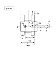
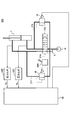
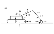
- FIG. 1 is a side view of a shovel 100 according to the present embodiment.
- the shovel 100 includes a lower traveling body 1, an upper swing body 3 mounted on the lower traveling body 1 so as to be pivotable via a swing mechanism 2, a boom 4 as an attachment, an arm 5, and a bucket 6. And a cabin 10 on which an operator boardes.
- the lower traveling body 1 (an example of a traveling body) includes, for example, a pair of left and right crawlers, and travels the shovel 100 by hydraulically driving the respective crawlers by the traveling hydraulic motors 1L and 1R (see FIG. 2 etc.)
- the upper swing body 3 (an example of a swing body) is turned with respect to the lower traveling body 1 by being driven by a swing hydraulic motor 21 (see FIG. 2) or the like described later.
- the boom 4 is pivotally mounted at the front center of the upper swing body 3, the arm 5 is pivotally mounted at the tip of the boom 4 so as to be vertically pivotable, and the bucket 6 is mounted at the tip of the arm 5 vertically It is pivotally attached.
- the boom 4, the arm 5 and the bucket 6 are hydraulically driven by a boom cylinder 7, an arm cylinder 8 and a bucket cylinder 9 as hydraulic actuators, respectively.
- the cabin 10 is a cockpit where an operator boardes, and is mounted on the front left side of the upper swing body 3.
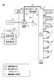
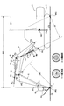
- FIG. 2 is a block diagram showing an example of a configuration centered on a drive system of the shovel 100 according to the present embodiment.
- the mechanical power system is indicated by a double line, the hydraulic fluid line (high pressure hydraulic line) by a thick solid line, the pilot line by a broken line, and the electric drive / control system by a thin solid line.
- the hydraulic drive system of the shovel 100 includes an engine 11, a main pump 14, and a control valve 17.
- the traveling hydraulic motors 1L and 1R hydraulically driving each of the lower traveling body 1, the upper swing body 3, the boom 4, the arm 5, and the bucket 6
- the motor 21, the boom cylinder 7, the arm cylinder 8, and the bucket cylinder 9 are included.
- the engine 11 is a driving force source of the shovel 100, and is mounted at the rear of the upper swing body 3, for example.
- the engine 11 is, for example, a diesel engine fueled with light oil.
- the main pump 14 and the pilot pump 15 are connected to the output shaft of the engine 11.
- the main pump 14 is mounted, for example, at the rear of the upper swing body 3 and supplies hydraulic fluid to the control valve 17 through the hydraulic fluid line 16.
- the main pump 14 is driven by the engine 11 as described above.
- the main pump 14 is, for example, a variable displacement hydraulic pump, and adjusts the stroke length of the piston by controlling the angle (tilting angle) of the swash plate by a regulator 14A (see FIG. 29 etc.) described later.
- the discharge flow rate (discharge pressure) can be controlled.
- the control valve 17 is, for example, a hydraulic control device mounted on the central portion of the upper swing body 3 and performing control of the hydraulic drive system in accordance with the operation of the operating device 26 by the operator.
- the traveling hydraulic motors 1L (for the left) and 1R (for the right), the boom cylinder 7, the arm cylinder 8, the bucket cylinder 9, the swing hydraulic motor 21 and the like are connected to the control valve 17 via a hydraulic fluid line.
- the control valve 17 is provided between the main pump 14 and each hydraulic actuator, and controls a plurality of hydraulic control valves that control the flow rate and the flow direction of hydraulic fluid supplied from the main pump 14 to each hydraulic actuator, that is, This is a valve unit including a direction switching valve (for example, a boom direction control valve 17A described later).
- the operation system of the shovel 100 includes the pilot pump 15, the operation device 26, the pressure sensor 29, and the like.
- the pilot pump 15 is mounted, for example, at the rear of the upper swing body 3 and supplies pilot pressure to the mechanical brake 23 and the operating device 26 via the pilot line 25.
- the pilot pump 15 is, for example, a fixed displacement hydraulic pump, and is driven by the engine 11 as described above.
- the operating device 26 includes lever devices 26A, 26B and a pedal device 26C.
- the operating device 26 is provided near the cockpit of the cabin 10, and is an operating means by which the operator operates the respective operating elements (the lower traveling body 1, the upper swing body 3, the boom 4, the arm 5, the bucket 6, etc.).
- the operation device 26 operates the respective hydraulic actuators (the traveling hydraulic motors 1L and 1R, the boom cylinder 7, the arm cylinder 8, the bucket cylinder 9, the swing hydraulic motor 21) and the like that drive the respective operating elements. It is a means.
- the operating device 26 (lever devices 26A, 26B and pedal device 26C) is connected to the control valve 17 via a pilot line 27.
- a pilot signal (pilot pressure) according to the operation state of the lower traveling body 1, the upper swing body 3, the boom 4, the arm 5, the bucket 6 and the like in the control device 26 is input to the control valve 17. Therefore, the control valve 17 can drive each hydraulic actuator in accordance with the operating state of the operating device 26. Also, the operating device 26 is connected to the pressure sensor 29 via the hydraulic line 28.
- the lever devices 26A and 26B are respectively disposed on the left and right sides when viewed from the operator seated in the cockpit in the cabin 10, with reference to the neutral state (state in which there is no operation input by the operator) of the respective operating levers. It is configured to be tiltable in the front-rear direction and the left-right direction.
- the upper swing body 3 is provided to the longitudinal tilt and the lateral tilt of the operating lever in the lever device 26A, and to the longitudinal tilt and the lateral tilt of the operating lever in the lever device 26B. Any of (swing hydraulic motor 21), boom 4 (boom cylinder 7), arm 5 (arm cylinder 8), and bucket 6 (bucket cylinder 9) may be set as an operation target.
- the pedal device 26C operates on the lower traveling body 1 (traveling hydraulic motors 1L and 1R) and is disposed on the front floor, as viewed from the operator who is seated at the cockpit in the cabin 10. It is configured to be possible to be stepped by the operator.
- the pressure sensor 29 is connected to the operating device 26 via the pilot line 28 as described above, and the pilot pressure on the secondary side of the operating device 26, ie, the pilot pressure corresponding to the operating state of each operating element in the operating device 26.
- the pressure sensor 29 is connected to the controller 30, and a pressure signal (pressure detection value) corresponding to the operation state of the lower traveling body 1, the upper swing body 3, the boom 4, the arm 5, and the bucket 6 in the operation device 26 is a controller It is input to 30.
- the controller 30 can grasp the operation state of the lower traveling body 1, the upper swinging body 3, and the attachment of the shovel.
- control system of the shovel 100 includes a controller 30, various sensors 32, and the like.
- the controller 30 is a main control device that performs drive control in the shovel 100.
- the controller 30 may be realized by any hardware, software, or a combination thereof.
- the controller 30 is mainly configured of a microcomputer including, for example, a central processing unit (CPU), a random access memory (RAM), a read only memory (ROM), an auxiliary storage device, and an input-output interface (I / O).
- Various kinds of drive control can be realized by executing various programs stored in the ROM, the auxiliary storage device, etc. on the CPU.
- the controller 30 determines whether or not a predetermined operation of the shovel 100 not intended by the operator (hereinafter simply referred to as an unintended operation), that is, the occurrence of the operation of the shovel 100 which is undesirable for the operator. Then, when it is determined that such an unintended operation has occurred, the controller 30 corrects the operation of the attachment of the shovel 100 so as to suppress the operation. Thereby, the unintended operation
- unintended operation for example, a forward drag operation in which the shovel 100 is dragged forward by an excavating reaction force or the like even though the lower traveling body 1 is not operated by the operator, or the shovel 100 is leveled Back dragging action that is dragged backward by the reaction force from the ground in
- the front dragging operation and the rear dragging operation may be simply referred to as a dragging operation without distinction.
- the unintended operation includes, for example, a floating operation in which the front portion or the rear portion of the shovel 100 is lifted by a digging reaction force or the like.
- the front lifting operation the case in which the front portion of the shovel 100 is lifted is referred to as the front lifting operation
- the case in which the rear portion of the shovel 100 is lifted is sometimes referred to as the rear lifting operation.
- a vehicle body lower traveling body 1, turning mechanism 2, etc.
- a change in moment of inertia is induced during aerial movement of the attachment of the shovel 100 (operation in a state where the bucket 6 is not grounded).
- the swinging motion of the upper swing body 3 Details of the unintended operation will be described later.
- the controller 30 includes, for example, an operation determination unit 301 and an operation correction unit 302 as functional units realized by executing one or more programs stored in a ROM or an auxiliary storage device on the CPU.
- the operation determination unit 301 determines the occurrence of an unintended operation based on sensor information regarding various states of the shovel 100, which is input from the pressure sensor 29 and the various sensors 32. Details of the determination method will be described later.
- the operation correction unit 302 corrects the operation of the attachment and suppresses the unintended operation. Details of the correction method will be described later.
- the various sensors 32 are known detection means for detecting various states of the shovel 100 and various states around the shovel 100.
- the various sensors 32 include an angle (boom angle) with respect to the reference surface of the boom 4 at a connection point between the upper swing body 3 and the boom 4 (a boom angle), a relative angle between the boom 4 and the arm 5 (arm angle), An angle sensor may be included to detect the relative angle (bucket angle) between the arm 5 and the bucket 6.
- the various sensors 32 may include a pressure sensor or the like that detects the hydraulic pressure state in the hydraulic actuator, specifically, the pressure in the rod side oil chamber and the bottom side oil chamber of the hydraulic cylinder.
- various sensors 32 include sensors that detect the operation states of the lower traveling body 1, the upper swing body 3, and the attachment, for example, an acceleration sensor, an angular acceleration sensor, a three-axis acceleration, and a three-axis angular acceleration.
- An output capable three-axis inertial sensor (IMU) or the like may be included.
- the various sensors 32 may include a distance sensor or an image sensor that detects the relative positional relationship with the terrain, obstacles, and the like in the vicinity of the shovel 100.
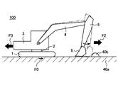
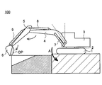
- FIG. 3 is a diagram for explaining the forward dragging operation of the shovel 100. As shown in FIG. Specifically, FIG. 3 is a diagram showing the work situation of the shovel 100 in which the front drag operation occurs.
- the shovel 100 excavates the ground 30 a, mainly by closing the arm 5 and the bucket 6, the vehicle body of the shovel 100 from the bucket 6 to the ground 30 a (lower traveling body 1, A diagonally downward force F2 acts on the turning mechanism 2 and the upper swing body 3).
- a reaction force of a force F2 acting on the bucket 6 to the vehicle body (lower traveling body 1, swing mechanism 2, upper swing body 3) of the shovel 100 that is, a horizontal component F2aH of the excavation reaction force F2a
- the corresponding reaction force F3 acts via the attachment.
- the reaction force F3 exceeds the maximum static friction force F0 between the shovel 100 and the ground 30a, the vehicle body is dragged forward.
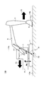
- FIG. 4 (FIG. 4A, FIG. 4B) is a figure explaining the back dragging operation
- FIG. 4A and FIG. 4B are diagrams showing the work situation of the shovel 100 in which the rear drag operation occurs.
- the shovel 100 is performing the leveling operation
- a reaction force F3 corresponding to the reaction force of the force F2 acting on the bucket 6 acts on the vehicle body of the shovel 100 through the attachment. Then, when the reaction force F3 exceeds the maximum static friction force F0 between the shovel 100 and the ground 40a, the vehicle body is dragged forward.
- the shovel 100 is carrying out river construction and the like, pressing the bucket 6 against the inclined wall surface 40c of the bank portion mainly by the opening operation of the arm 5 to solidify the soil and level the ground I am working. Also in such an operation, the reaction force F3 corresponding to the reaction force of the force F2 pressing the wall surface 40c acting on the bucket 6 acts to drag the vehicle body from the attachment to the rear.
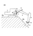
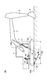
- FIG. 5 is a view for explaining the front lifting operation of the shovel 100. As shown in FIG. Specifically, FIG. 5 is a diagram showing a working situation of the shovel 100 in which the front lifting operation occurs.
- the shovel 100 excavates the ground 50 a, and mainly from the bucket 6 to the ground 50 a by the closing operation of the arm 5 and the bucket 6, obliquely downward toward the vehicle body of the shovel 100.
- Force F2 acts.
- the reaction force of the force F2 acting on the bucket 6 that is, the reaction force F3 for tilting the vehicle body corresponding to the vertical direction component F2aV of the digging reaction force F2a
- Moment of force hereinafter referred to simply as "moment” in the present embodiment
- the reaction force F3 acts on the vehicle body as a force F1 for pulling up the boom cylinder 7.
- the moment to incline the vehicle body backward due to the force F1 exceeds the force (moment) to press the vehicle body to the ground based on gravity, the front part of the vehicle body is lifted.
- FIG. 6 is a view for explaining the rear lifting operation of the shovel 100. Specifically, FIG. 6 is a diagram showing the working situation of the shovel 100 in which the rear lifting operation occurs.
- the shovel 100 is carrying out the digging operation of the ground 60a.
- a force F2 (moment) is generated so that the bucket 6 digs the slope 60b, and the boom 4 leans forward so that the boom 4 holds the bucket 6 against the slope 60b.
- Force F3 (moment) is generated.
- a force F1 for pulling up the rod of the boom cylinder 7 is generated, and the force F1 acts to tilt the body of the shovel 100.
- the moment to lean the vehicle body forward due to the force F1 exceeds the force to press the vehicle body against the ground based on gravity, the front part of the vehicle body is lifted.
- the rod of the boom cylinder 7 is not displaced because the boom 4 does not move even if a force is applied to the boom 4.
- the force F1 for lifting the boom cylinder 7 itself that is, the force to lean the vehicle body forward increases.
- Such a situation may occur, for example, in deep digging work in which the bucket 6 is positioned lower than the vehicle body (lower traveling body 1) in addition to the ground leveling work on the front slope shown in FIG. Moreover, not only when boom 4 itself is operated but when arm 5 and bucket 6 are operated, it may arise.
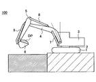
- FIG. 7 (FIG. 7A, FIG. 7B) and FIG. 8 are diagrams for explaining an example of the vibration operation of the shovel 100.
- FIG. 7 is a view for explaining a situation in which the vibration operation occurs when the shovel 100 operates in the air.
- FIG. 8 is a figure which shows the time waveform of the angle (pitch angle) and angular velocity (pitch angular velocity) of the pitching axial direction accompanying the discharge
- a discharge operation for discharging the load DP in the bucket 6 will be described as an example of the air movement.
- the shovel 100 is in a state in which the bucket 6 and the arm 5 are closed and the boom 4 is raised, and the bucket 6 contains a load DP such as earth and sand.
- a load DP such as earth and sand.
- FIG. 9 is a diagram schematically illustrating a method of suppressing an unintended operation of the shovel 100.
- FIGS. 9A to 9D are plan views of the shovel 100 showing the state of the shovel 100 in which the combination of the direction of the lower traveling body 1 and the turning position of the upper swing body 3 are different from each other.
- the attachment that is, the boom 4, the arm 5, and the bucket 6 is always on the straight line L1 corresponding to the extension direction of the attachment when viewed in a plan view, that is, the same vertical plane regardless of its posture or work content. Work on. Therefore, it can be said that, during the operation of the attachment, the reaction force F3 acting from the attachment acts on the vehicle body of the shovel 100 on the vertical plane. This does not depend on the positional relationship (turning angle) between the lower traveling unit 1 and the upper swinging unit 3. As shown in FIGS. 3 to 7, the orientation of the reaction force F3 in a plan view can differ depending on the work content.
- FIG. 10 is a diagram schematically illustrating an example of a method of suppressing the front drag operation of the shovel 100.
- FIG. 10 is a view showing an example of a mechanical model of the shovel 100 related to the forward drag operation, and as in FIG. 3, when the shovel 100 is carrying out an excavating operation on the ground 100 a It is a figure which shows the force to act.
- FIG. 11 is a figure which illustrates roughly an example of the suppression method of back dragging operation
- FIG. 11 is a view showing an example of a dynamic model related to the rear drag operation, and more specifically, the shovel 100 performs the work of leveling the soil 110 b on the ground 110 a as in FIG. 4A. It is a figure which shows the force which acts on the shovel 100, when it exists.
- the force F3 by which the boom cylinder 7 pushes the vehicle body (the upper revolving superstructure 3) in the horizontal direction (one of front and back) is an angle 11 formed by the boom cylinder 7 and the vertical axes 100c and 110c.
- the following equation (1) is expressed based on the force F1 exerted by the boom cylinder 7 on the upper swing body 3, that is, the force F1 exerted on the vehicle body from the attachment.
- the maximum static friction force F0 is expressed by the following equation (2) based on the static friction coefficient ⁇ between the lower traveling body 1 and the ground 100a, 110a, the vehicle body weight M, and the gravitational acceleration g.
- the motion correction unit 302 can suppress the rear drag operation of the shovel 100 by correcting the motion of the boom cylinder 7 such that the relational expression of Expression (4) holds.
- the force F1 is a function f with the pressure (rod pressure) PR of the rod side oil chamber of the boom cylinder 7 and the pressure (bottom pressure) PB of the bottom side oil chamber as arguments Is represented by
- the motion correction unit 302 calculates (estimates) the force F1 exerted by the boom cylinder 7 on the upper swing body 3 based on the rod pressure PR and the bottom pressure PB based on the equation (5). At this time, the motion correction unit 302 may obtain the rod pressure PR and the bottom pressure PB based on the output signal of the pressure sensor that detects the rod pressure and the bottom pressure of the boom cylinder 7 that can be included in the various sensors 32.
- the force F1 can be expressed by the following equation (6) using the pressure receiving area AR on the rod side and the pressure receiving area AB on the bottom side.
- the motion correction unit 302 may calculate (estimate) the force F1 based on Expression (6).
- the motion correction unit 302 calculates an angle 11 formed by the vertical axes 100c and 110c and the boom cylinder 7.
- the angle ⁇ 1 can be geometrically calculated from the extension / contraction length of the boom cylinder 7, the dimension specification of the shovel 100, the inclination of the vehicle body of the shovel 100, and the like.
- the motion correction unit 302 may calculate the angle ⁇ 1 using the output of a sensor that detects the boom angle that can be included in the various sensors 32.
- the angle ⁇ 1 may be obtained by using the output of a sensor that directly measures the angle 11 that may be included in the various sensors 32.
- the motion correction unit 302 sets the pressure of the boom cylinder 7, specifically, the rod-side oil chamber or so that equation (4) holds based on the force F1 and the angle 11 acquired by calculation or the like.
- the pressure of one of the bottom side oil chambers is controlled. That is, the motion correction unit 302 (pressure adjustment unit) adjusts the rod pressure PR or the bottom pressure PB of the boom cylinder 7 so that the equation (4) is established. More specifically, by adopting various configurations described later (see FIGS. 26 to 34), the operation correction unit 302 adjusts the pressure of the boom cylinder 7 by appropriately outputting the control command to the control target. The drag operation of the shovel 100 can be suppressed.
- a typical predetermined value may be used as the static friction coefficient ⁇ in the equation (4), or may be input by the operator according to the condition of the work ground.
- the shovel 100 may further include means for estimating the static friction coefficient ⁇ . Specifically, in the state where the shovel 100 stands still with respect to the ground, the estimation means calculates the static friction coefficient ⁇ from the force F1 when the slip (drag) of the vehicle body occurs during the work by the attachment. Can. In this case, for example, as described later, the presence or absence of the drag may be determined by appropriately mounting an acceleration sensor or the like on the upper swing body 3 of the shovel 100.
- FIG. 12 is a figure which roughly illustrates an example of the suppression method of the front part floating operation of the shovel 100.
- FIG. 12 is a diagram showing a mechanical model of the shovel 100 related to the front lifting operation, and similar to FIG. 5, when the shovel 100 is carrying out a digging operation on the ground 120 a
- FIG. 7 is a diagram showing a force acting on 100.
- the fall fulcrum P1 in the front lifting operation of the shovel 100 is the rearmost end in the direction in which the attachment extends (the direction of the upper revolving unit 3) in the effective ground area 120b of the lower traveling unit 1 It can be regarded. Therefore, based on the force F1 and the distance D3 between the extension line 12 of the boom cylinder 7 and the fall support point P1, the moment ⁇ 1 for lifting the front of the vehicle body around the fall support point P1 is given by the following equation (7) expressed.
- the moment ⁇ 2 at which gravity attempts to hold the vehicle body to the ground around the fall support point P1 is the distance D1 between the vehicle body center of gravity P3 of the shovel 100 and the fall support point P1 behind the lower traveling body 1 and the vehicle weight It is represented by the following formula (8) based on M and the gravitational acceleration g.
- a condition (stable condition) in which the front portion of the vehicle body is stabilized without rising is represented by the following equation (9).
- the motion correction unit 302 can prevent the front floating motion of the shovel 100 by correcting the motion of the attachment such that inequality (10) holds as the control condition.
- FIG. 13 is a diagram showing a mechanical model of the shovel related to the rear uplift, which acts on the shovel 100 when excavating work on the ground 130a as in FIG. FIG.
- the fall fulcrum P1 in the rear lifting operation of the shovel 100 can be regarded as the cutting edge in the direction in which the attachment extends (the direction of the upper swing body 3) in the effective contact area 130b of the lower traveling body 1. Therefore, the moment ⁇ 1 for tilting the vehicle body forward around the fall fulcrum P1, ie, the moment ⁇ 1 for lifting the rear of the vehicle, is the extension line 12 of the boom cylinder 7 and the distance D4 between the fall fulcrum P1. Based on the force F 1 exerted on the upper swing body 3 by the boom cylinder 7, the following equation (11) is expressed.
- the motion correction unit 302 can prevent the rear floating motion of the shovel 100 by correcting the motion of the attachment such that inequality (14) holds as the control condition.
- control condition (stable condition) of the front lift and the rear lift is as follows It can be summarized as (15).
- the force F1 is expressed by a function f with the rod pressure PR and the bottom pressure PB of the boom cylinder 7 as arguments, as shown in the following equation (16), as in the above equation (5).
- the motion correction unit 302 calculates (estimates) the force F1 exerted by the boom cylinder 7 on the upper swing body 3 based on the rod pressure PR and the bottom pressure PB. At this time, as described above, the motion correction unit 302 acquires the rod pressure PR and the bottom pressure PB based on the output signal of the pressure sensor that detects the rod pressure and the bottom pressure of the boom cylinder 7 that can be included in the various sensors 32. You may
- the force F1 can be expressed by the following equation (17) using the pressure receiving area AR on the rod side and the pressure receiving area AB on the bottom side, as in the above-mentioned equation (6).
- the motion correction unit 302 may calculate (estimate) the force F1 based on Expression (17).
- the operation correction unit 302 acquires the distances D1 and D3 or the distances D2 and D4. Also, the operation correction unit (distance acquisition unit) may acquire their ratio (D1 / D3 or D2 / D4).
- the position of the vehicle body center of gravity P3 excluding the attachment is constant regardless of the turning angle ⁇ of the upper swing body 3, but the position of the overturning fulcrum P1 changes according to the turning angle ⁇ . Therefore, the distances D1 and D2 may actually change in accordance with the turning angle ⁇ of the upper swing body 3, but the distances D1 and D2 may be constant for the sake of simplicity.
- the distances D3 and D4 can be geometrically calculated based on the position of the fall support point P1 and the angle of the boom cylinder 7 (for example, the angle 11 formed by the boom cylinder 7 and the vertical axis 130c).
- the angle ⁇ 1 can be geometrically calculated from the extension / contraction length of the boom cylinder 7, the dimension specification of the shovel 100, the inclination of the vehicle body of the shovel 100, and the like.
- the motion correction unit 302 may calculate the angle ⁇ 1 using the output of a sensor that detects the boom angle that can be included in the various sensors 32.
- the angle ⁇ 1 may be obtained by using the output of a sensor that directly measures the angle 11 that may be included in the various sensors 32.
- the motion correction unit 302 determines inequality (15), that is, inequality (10) or (14) based on the force F1 obtained by calculation or the like and the distances D1 and D3 or the distances D2 and D4. To control the pressure of the boom cylinder 7, specifically, the pressure of one of the rod-side oil chamber and the bottom-side oil chamber. That is, the motion correction unit 302 (pressure adjustment unit) adjusts the rod pressure PR or the bottom pressure PB of the boom cylinder 7 so that inequality (15) is satisfied. More specifically, by adopting various configurations described later (see FIGS. 26 to 34), the operation correction unit 302 adjusts the pressure of the boom cylinder 7 by appropriately outputting the control command to the control target. The lifting operation of the shovel 100 can be suppressed.
- control conditions (stable conditions) in which the front lifting and the rear lifting do not occur are the inequality (15), that is, the inequalities (10) and (14).
- Inequalities (10) and (14) take the distances D1, D2, D3, and D4 as parameters, and these distances depend on the position of the fall support point P1.
- FIG. 14 when the direction in which the attachment extends (the orientation of the attachment) and the direction of the lower traveling body 1 (the traveling direction) are the same, the turning angle It is a figure explaining the relationship between the fall fall fulcrum P1 in the case of making it a positive direction, and direction (turning angle (theta)) of the upper turning body 3.
- FIG. Specifically, FIGS. 14A to 14C are diagrams showing the fall fulcrum P1 in the case where the turning angle ⁇ is 0 °, 30 °, and 90 °, respectively.
- FIG. 15 is a view for explaining the relationship between the overturning fulcrum P1 and the state of the ground 150a (working field).
- the fall fulcrum P1 is located at the front of the vehicle body.
- line l1 in FIGS. 14A to 14C is a line perpendicular to the direction in which the attachment extends (the direction of the upper swing body 3) and passing through the tip in the extension direction of the attachment in the effective ground area 140a.
- the fall fulcrum P1 is located on the line l1.
- a solid line represents the hard ground 150a
- a dashed dotted line represents the soft ground 150b.
- the overturning fulcrum P1 moves in accordance with the direction of the upper swing body 3 and the state of the ground.
- the distance D2 when the overturning fulcrum P1 moves, the distance D2 also changes. Similarly, the distance D4 also changes with the movement of the overturning fulcrum P1.
- the fall supporting point P1 is present at a solid triangle position on the hard ground 150a.
- the overturning fulcrum P1a can exist at a triangular position of a dashed dotted line.
- the overturning fulcrum P1 can move further.
- the movement of the fall fulcrum P1 affects the distances D1 to D4, and affects the dynamic stability condition that the vehicle body does not fall. Therefore, the operation correction unit 302 sets a control condition (stable condition) according to the position of the fall support point P1, and corrects the attachment operation so that the floating operation of the shovel 100 is suppressed based on the set control condition.
- the operation determination unit 301 monitors the states of the vehicle body and the attachment based on the inputs from the various sensors 32, and specifies the moment when the front or rear of the lower traveling vehicle 1 is lifted.
- the motion correction unit 302 then performs control conditions (stable conditions) for correcting the motion of the attachment, that is, the inequalities (10) and (14) as an example at the moment when the vehicle body (lower traveling body 1) rises. It changes dynamically based on the state of the shovel 100.
- the moment of floating can be approximated as a state in which a moment ⁇ 1 based on a force F1 at which the attachment tries to lean the vehicle body and a moment ⁇ 2 based on gravity against it are balanced. Therefore, by identifying the moment of floating and monitoring the state of the shovel 100, the control conditions for suppressing the floating can be adaptively set, and the floating can be appropriately suppressed under various usage conditions.
- the operation determination unit 301 specifies (detects) the floating moment of the shovel 100 (lower traveling body 1) based on the input from the various sensors 32.
- the sensor 610 may be included in various sensors 32, and may be a pitch axis based on outputs from an attitude sensor (tilt sensor) mounted on the upper swing body 3, a gyro sensor (angular acceleration sensor), an acceleration sensor, an IMU, etc. The rotation around may be detected and the moment of lifting may be identified.
- the motion correction unit 302 sets a control condition for suppressing upward lift.
- the motion correction unit 302 (control condition setting unit) is configured to suppress the front uplift when the motion determination unit 301 detects forward and backward angular acceleration or angular velocity based on the outputs of the various sensors 32. Set control conditions.
- the motion correction unit 302 acquires a force F1 (force F1_INIT) exerted on the upper swing body 3 by the boom cylinder 7 at the moment of floating identified (detected) by the motion determination unit 301. Then, the operation correction unit 302 (condition setting unit) acquires a parameter related to the position of the overturning fulcrum P1 based on the acquired force F1_INIT, and sets a control condition based on the parameter.
- the above inequality (10) is used as a control condition for suppressing the front lift.
- the motion correction unit 302 acquires the current distances D1 and D3 (distances D1_DET and D3_DET) based on Expression (18) and the posture of the attachment.
- acquiring the distance D1 is equivalent to acquiring the position information of the overturning fulcrum P1. Since the position of the vehicle body center of gravity P3 is unchanged, the position of the overturning fulcrum P1 is uniquely determined if the distance D1 is obtained.
- the operation correction unit 302 (condition setting unit) sets the subsequent control conditions to the following inequality (19).
- the motion correction unit 302 corrects the motion of the attachment based on the control condition represented by Expression (19).
- the operation correction unit 302 (condition setting unit) changes the distance D3 according to the change and reflects the change in the control condition.
- the motion correction unit 302 acquires the current distances D2 and D4 (distances D2_DET and D4_DET) based on Expression (18) and the posture of the attachment.
- acquiring the distance D2 is equivalent to acquiring the position information of the overturning fulcrum P1.
- the operation correction unit 302 (condition setting unit) sets the subsequent control conditions to the following inequality (21) based on the above inequality (14).
- the motion correction unit 302 corrects the motion of the attachment based on the control condition represented by Expression (21).
- the operation correction unit 302 (condition setting unit) changes the distance D4 according to the change and reflects the change in the control condition.
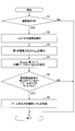
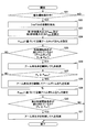
- FIG. 16 is a flowchart schematically showing an example of processing (condition setting processing) for setting control conditions by the controller 30 (the operation determination unit 301 and the operation correction unit 302).
- the process according to this flowchart may be performed, for example, periodically, that is, at predetermined time intervals, from when the shovel is started to when it stops.
- step S1600 operation determination unit 301 determines whether or not an excavation operation using an attachment is in progress.
- the determination condition for determining whether or not the drilling operation using the attachment is in progress is, for example, at least one of the boom cylinder 7, the arm cylinder 8, and the bucket cylinder 9 while not traveling and not turning.
- the pressure above the predetermined pressure may be generated.
- the operation determination unit 301 proceeds to step S1602 when the digging operation is being performed, and ends the current process when the digging operation is not being performed.
- Excavating work includes leveling work and backfilling work.
- step S1602 the operation determination unit 301 monitors the presence or absence of the floating operation of the shovel 100. If the motion determination unit 301 specifies (detects) the floating, the process proceeds to step S 1804. If the floating is not specified (detected), the operation determining unit 301 ends the current process.
- step S1602 before setting the control condition, the vehicle body of the shovel 100 is lifted for a moment. If an appropriate combination of processor and software program is used in the controller 30, after identifying (detecting) the floating, control conditions are very short, before the first floating in step S1602 develops to a large inclination of the vehicle body. Can be set. Then, the motion correction unit 302 can start the motion correction of the attachment before developing to a large inclination of the vehicle body.
- step S1604 the operation correction unit 302 acquires information on the state of the shovel 100 at the moment of floating.
- the information related to the state of the shovel 100 is, for example, the above-described force F1_INIT.
- step S1606 the operation correction unit 302 calculates parameters regarding the overturning fulcrum P1, for example, the distances D1 to D4, based on the information on the state of the shovel acquired in step S1604, and sets control conditions. Thereafter, the operation correction unit 302 corrects the operation of the attachment based on the set control condition until the current excavation work is completed, unless the control condition is corrected by the process of step S1610 described later.
- step S1608 the operation determination unit 301 determines whether or not the attitude of the boom 4 has changed. If the posture of the boom 4 has changed, the operation determination unit 301 proceeds to step S1610, and if not, the operation proceeds to step S1612.
- step S1610 the motion correction unit 302 corrects the control condition because the distances D3 and D4 change in accordance with the change in posture of the boom 4.
- step S1612 the operation determination unit 301 determines whether the digging operation has been completed. If the excavation work has not been completed, the operation determination unit 301 returns to step S1608. If the excavation work has been completed, the operation determination unit 301 ends the current process.
- control conditions are defined by calculating the distances D1 to D4, but the control conditions are not limited thereto.
- the control conditions are not limited thereto. For example, when the inequalities (10) and (14) are transformed, the following inequalities (22) and (23) are obtained.
- F1_INIT D1 / D3 ⁇ Mg (24)
- F1_INIT D2 / D4 ⁇ Mg (25)
- the operation correction unit 302 (condition setting unit) may obtain the force F1_INIT at the moment of floating, and set the control condition thereafter to equation (26).
- control conditions represented by the equation (26) reflect the correct position information of the overturning fulcrum P1. ing.
- the force F1 is explicitly included in the control conditions for suppressing uplift, it is not the limitation.
- the control condition may be defined using another force or moment or the like that has a correlation with the force F1 instead of the force F1.
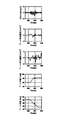
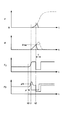
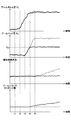
- FIG. 17 is a diagram showing a specific example of operation waveforms related to the vibration operation of the shovel 100.
- FIG. Specifically, FIGS. 17A to 17C are diagrams showing an example, another example and further another example of an operation waveform chart in the case where the air movement is repeatedly performed in the shovel 100.
- FIGS. 17A-17C respectively show different trials, and from the top, pitching angular velocity (ie, vehicle vibration), boom angular acceleration, arm angular acceleration, boom angle, and arm angle are shown.
- X marks indicate points corresponding to negative peaks of the pitch angular velocity.
- the motion correction unit 302 corrects the motion of the boom cylinder 7 as a control target. That is, the motion correction unit 302 operates such that the thrust of the boom cylinder 7 does not exceed the upper limit value (limit thrust FMAX) based on the state of the attachment.
- limit thrust FMAX the upper limit value
- the thrust force F of the boom cylinder 7 is based on the pressure receiving area AR of the rod side oil chamber, the rod pressure PR of the rod side oil chamber, the pressure receiving area AB of the bottom side oil chamber, and the bottom pressure PB of the bottom side oil chamber. It is expressed by (27).
- the motion correction unit 302 corrects the motion of the attachment, that is, the motion of the boom cylinder 7 so that equation (30) is established. That is, the motion correction unit 302 adjusts the bottom pressure PB of the boom cylinder 7 so that the equation (30) is established. More specifically, by adopting various configurations (see FIGS. 27 to 35) to be described later, the operation correction unit 302 appropriately outputs the control command to the control target, so that the bottom pressure PB of the boom cylinder 7 is obtained. Can be adjusted to suppress the vibration operation of the shovel 100.
- the motion correction unit 302 acquires the limited thrust FMAX based on detection signals from the various sensors 32.
- the limit thrust obtaining unit 586 obtains the limit thrust FMAX by the operation of the attachment, that is, the detection signal from the various sensors 32 as an input.
- the operation correction unit 302 can calculate the upper limit value PBMAX of the bottom pressure PB from the equation (30), and can adjust the bottom pressure PB of the boom cylinder 7 so as not to exceed the calculated upper limit value PBMAX.
- the motion correction unit 302 acquires a thrust (holding thrust FMIN) capable of holding the attitude of the boom 4 and a range higher than the holding thrust FMIN. It is better to set the limit thrust FMAX.
- FIG. 18 is a diagram for explaining a method of acquiring the limited thrust FMAX by the operation correction unit 302.
- FIG. 18 is a block diagram showing a configuration related to an acquisition function of the limited thrust FMAX in the operation correction unit 302. As shown in FIG.
- the motion correction unit 302 acquires (sets) the limited thrust FMAX based on table reference.
- the operation correction unit 302 includes a first lookup table 600, a second lookup table 602, a table selector 604, and a selector 606.
- the first look-up table 600 receives a boom angle ⁇ 1 which is an output of a boom angle sensor included in various sensors 32, and outputs a limited thrust FMAX.
- the first look-up table 600 may include a plurality of tables provided corresponding to a plurality of different states of the shovel 100 defined in advance.
- the second lookup table 602 receives the boom angle sensor 1 and the arm angle ⁇ 2 output from the boom angle sensor and the arm angle sensor included in the various sensors 32, and outputs the holding thrust force FMIN. Similar to the first look-up table 600, the second look-up table 602 may include a plurality of tables provided corresponding to a plurality of different states of the shovel 100 defined in advance.
- the table selector 604 is a bucket angle sensor included in various sensors 32 from the first lookup table 600, and a bucket output from a pitch angle sensor and a swing angle sensor mounted on a vehicle body (upper swing body 3).
- An optimum table is selected using at least one of the angle ⁇ 3, the pitch angle ⁇ P of the vehicle body, and the swing angle ⁇ S as parameters.
- the table selector 604 selects an optimum table from among the second look-up table 602, using at least one of the bucket angle ⁇ 3, the pitch angle ⁇ P of the vehicle body, and the swing angle ⁇ S as a parameter.
- the selector 606 outputs the larger one of the limit thrust FMAX and the holding thrust FMIN. Thereby, the vibration operation can be suppressed while preventing the lowering of the boom.
- the motion correction unit 302 may obtain the limited thrust FMAX by arithmetic processing instead of referring to the table. Similarly, the motion correction unit 302 may obtain the holding thrust force FMIN by arithmetic processing instead of referring to the table.
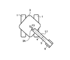
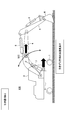
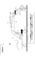
- FIG. 19 (FIG. 19A, FIG. 19B) is a figure explaining the 1st example of the determination method of generation
- FIG. Specifically, FIG. 19 is a view for explaining an example of the attachment position of the acceleration sensor 32A attached to the upper swing body 3 of the shovel 100. As shown in FIG.
- the various sensors 32 of the shovel 100 according to the present embodiment include an acceleration sensor 32A.
- the acceleration sensor 32A is mounted on the upper swing body 3.
- the acceleration sensor 32A has a detection axis in a direction along a straight line L1 corresponding to the extension direction of the attachment when the shovel 100 is viewed in a plan view.
- the point of action of the force exerted by the attachment on the upper swing body 3 is the root 3A of the boom 4. Therefore, it is desirable that the acceleration sensor 32A be provided at the base 3A of the boom 4.
- the operation determination unit 301 can appropriately identify the occurrence of the drag operation of the shovel 100 due to the operation of the attachment based on the output signal of the acceleration sensor 32A.
- the acceleration sensor 32A moves away from the pivot shaft 3B, the acceleration sensor 32A is influenced by the centrifugal force due to the pivoting motion when the upper pivoting body 3 pivots. Therefore, it is desirable to dispose the acceleration sensor 32A in the vicinity of the root 3A of the boom 4 and in the vicinity of the pivot axis 3B.
- the acceleration sensor 32A be disposed in a region R1 between the base 3A of the boom 4 and the pivot shaft 3B of the upper swing body 3.
- the influence of the swinging motion included in the output of the acceleration sensor 32A can be reduced, so that the operation determination unit 301 can suitably detect the dragging operation resulting from the operation of the attachment based on the output of the acceleration sensor 32A.
- the acceleration sensor 32A when the position of the acceleration sensor 32A is too far from the ground, an acceleration component caused by pitching or rolling tends to be included in the output of the acceleration sensor 32A. From this viewpoint, it is preferable that the acceleration sensor 32A be disposed on the lower side of the upper swing body 3 as much as possible.
- the operation determination unit 301 can identify the occurrence of the drag operation of the shovel 100 based on the output corresponding to the speed along the straight line L1 detected by the speed sensor.
- the various sensors 32 may further include an angular velocity sensor mounted on the upper swing body 3 in addition to the acceleration sensor 32A.
- the operation correction unit 302 may correct the output of the acceleration sensor 32A based on the output of the angular velocity sensor.
- the output of the acceleration sensor 506 may include not only the linear movement (drag movement) in a specific direction, but also components of rotational movement in the pitching direction, the yawing direction, and the rolling direction. According to this modification, by using the angular velocity sensor in combination, it is possible to extract only the linear movement corresponding to the dragging operation without the influence of the rotation movement, so that the determination accuracy of the dragging operation by the operation determination unit 301 Can be improved.
- the acceleration sensor 32A is provided on the upper swing body 3, but may be provided on the lower traveling body 1.
- the operation determination unit 301 outputs the output of the acceleration sensor 32A of the lower traveling body 1 From this, it is possible to specify the linear movement along the extension direction (straight line L1) of the attachment, and to specify the occurrence of the dragging operation in that direction.
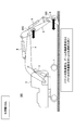
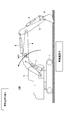
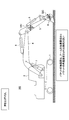
- FIG. 20 is a figure explaining the 2nd example of the determination method of generation
- the various sensors 32 include a distance sensor 32B.
- the distance sensor 32B is attached to the front end of the upper swing body 3 of the shovel 100, and the terrain, obstacles, etc. in the predetermined range in front of the upper swing body 3 of the shovel 100 Measure the distance to the vehicle body (upper revolving unit 3) to which is attached.
- the distance sensor 32B is, for example, LIDAR (Light Detection and Ranging), millimeter wave radar, stereo camera or the like.
- the movement determination unit 301 generates the drag movement of the shovel 100 based on the change in the relative positional relationship between the upper swing body 3 and the fixed reference object around the shovel 100, which is measured by the distance sensor 32B. Determine Specifically, based on the output of the distance sensor 32B, the motion determination unit 301 determines that the relative position of the ground 200a viewed from the upper swing body 3 is substantially horizontal, specifically, substantially parallel to the plane on which the shovel 100 is located. When it moves to, it can be determined that a drag operation has occurred. For example, as shown in FIG.
- the operation determination unit 301 makes the relative position of the ground 200a in front of the upper swing body 3 closer to the upper swing body 3 (dotted line 200b When moving approximately horizontally to the position), it can be determined that the forward drag operation of the shovel 100 has occurred. Conversely, the operation determination unit 301 can determine that the rear drag operation of the shovel 100 has occurred when moving substantially horizontally away from the upper swing body 3 on the ground 200 a in front as viewed from the upper swing body 3.
- the motion determination unit 301 is not limited to the distance sensor 32B, but may be another sensor capable of detecting the relative positional relationship between the upper swing body 3 and the fixed reference object around the shovel 100, for example, an image sensor The camera) may be used to determine the occurrence of the dragging operation.
- the fixed reference object of the shovel 100 is not limited to the ground, and may be a specific object or the like intentionally disposed around the shovel 100 for the purpose of use as a structure or a reference object.
- the distance sensor 32B may be attached to the attachment instead of the upper swing body 3.
- the operation determination unit 301 may be capable of measuring not only the distance between the attachment and the reference object but also the distance between the attachment and the upper swing body 3.
- the motion determination unit 301 can specify the relative position of each of the reference object and the upper swing body 3 viewed from the attachment based on the output of the distance sensor 32B, that is, indirectly, the upper swing
- the relative positional relationship between the body 3 and the reference object can be determined. Therefore, the relative movement between the upper swing body 3 and the reference object changes based on the output of the distance sensor 32B mounted on the attachment, and the motion determination unit 301 changes the upper swing body 3 as viewed from the upper swing body 3. When it moves substantially parallel to the plane where it is located, it can be determined that a dragging operation has occurred.
- FIG. 21 (FIG. 21A, FIG. 21B) is a figure explaining the 3rd example of the determination method of generation
- the various sensors 32 include an IMU 32C.
- the IMU 32C is attached to the boom 4.
- the longitudinal acceleration component detected by the IMU 32C is , Is output as a relatively small value by the rotational movement.
- the operation determination unit 301 may determine that the drag operation has occurred.
- the predetermined threshold may be appropriately set based on experiments, simulation analysis, and the like. Further, the operation determination unit 301 can determine whether it is a front drag operation or a rear drag operation, according to the direction of the detected acceleration component.
- a speed sensor, an acceleration sensor, or the like may be employed instead of the IMU 32C as long as the motion of the boom 4 in the front-rear direction can be detected.
- the operation determination unit 301 may determine that the drag operation has occurred when the output value of the sensor becomes relatively large.
- FIG. 22 (FIG. 22A, FIG. 22B) is a figure explaining the 4th example of the determination method of generation
- FIG. 22A shows the shovel 100 when the dragging operation is not generated
- FIG. 22B shows the shovel 100 when the dragging operation is generated.
- the various sensors 32 include two IMUs 32C.
- one IMU 32 C is attached to the arm 5 and the other IMU 32 C is attached to the bucket 6 as shown in FIGS. 22A and 22B.
- the acceleration component in the front-rear direction detected by the IMU 32C of the bucket 6 is the acceleration component of the arm 5 and the angular acceleration component around the drive axis of the bucket 6 Is represented by the synthesis of Therefore, the acceleration component detected by the IMU 32C of the bucket 6 becomes relatively larger than the acceleration component in the front-rear direction detected by the IMU 32C of the arm 5.
- the operation determination unit 301 may determine that the drag operation has occurred, for example, when the difference between the acceleration components detected by the IMU 32C of the arm 5 and the bucket 6 becomes equal to or greater than a predetermined threshold.
- the predetermined threshold may be appropriately set based on experiments, simulation analysis, and the like. Further, the operation determination unit 301 can determine whether it is a front drag operation or a rear drag operation according to the direction of the acceleration component of the arm 5.
- the IMU 32C attached to the arm 5 is disposed closer to the connection position of the boom 4 and the arm 5 than the connection position of the arm 5 and the bucket 6 as much as possible.
- the operation determination unit 301 can more easily determine the drag operation based on the difference between the acceleration components detected by the IMU 32C of each of the arm 5 and the bucket 6.
- a velocity sensor, an acceleration sensor, or the like may be employed instead of the IMU 32C as long as the longitudinal movement of the arm 5 and the bucket 6 can be detected.
- IMU 32C is attached to arm 5 and bucket 6, it may be attached to boom 4 further. This makes it possible to determine the presence or absence of the dragging operation not only from the difference between the output values of the IMU 32C of the arm 5 and the bucket 6 but also from the difference between the output values of the IMU 32C of the boom 4 and the bucket 6 Can be enhanced.
- the IMU 32C of the arm 5 may be attached to the boom 4. In this case, the presence or absence of the dragging operation can be determined from the difference between the output values of the IMU 32C of the boom 4 and the bucket 6 respectively.
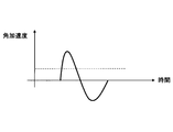
- FIG. 23 is a view for explaining a first example of the method of determining the occurrence of the floating operation of the shovel 100.
- FIG. 23A to FIG. 23C are diagrams showing temporal changes in tilt angle, angular velocity, and angular acceleration in the front-rear direction (pitch direction) of the vehicle body when the lifting operation of the shovel occurs, respectively.
- the operation determination unit 301 lifts up the shovel 100 based on the output of a sensor that can output angle-related information on the inclination in the front-rear direction of the vehicle body, that is, the inclination angle in the pitch direction. To determine the occurrence of
- An inclination sensor (angle sensor), an angular velocity sensor, an IMU or the like may be employed as a sensor capable of outputting angle-related information (inclination angle, angular velocity, angular acceleration, etc.) regarding the inclination angle in the pitch direction of the vehicle body.
- the motion determination unit 301 may determine whether the front lifting operation or the rear lifting operation is performed based on the tilt angle, the angular velocity, and the generation direction of the angular acceleration, that is, the rear tilt or the front tilt around the pitch axis. it can.
- FIG. 24 is a diagram for explaining a second example of the method of determining the occurrence of the floating operation.
- the various sensors 32 include the distance sensor 32B as in the case of FIG.
- the distance sensor 32B is attached to the front end of the upper swing body 3 of the shovel 100 as in the case of FIG. The distance between an obstacle or the like and the vehicle body (upper revolving unit 3) to which the vehicle is attached is measured.
- the motion determination unit 301 is based on the change in relative positional relationship between the upper swing body 3 and the fixed reference object around the shovel 100, which is measured by the distance sensor 32B.
- the occurrence of the floating motion of the shovel 100 is determined.
- the motion determination unit 301 determines that the relative position of the ground 240a viewed from the upper swing body 3 is substantially vertical, specifically, substantially perpendicular to the plane on which the shovel 100 is located. When moving in any direction, it can be determined that the floating operation has occurred. For example, as shown in FIG.
- the operation determining unit 301 causes the relative position of the ground 200a in front of the upper swing body 3 to be approximately downward (dotted line 240b in the figure) based on the output of the distance sensor 32B.
- the motion determination unit 301 can determine that the rear lifting operation of the shovel 100 has occurred when the relative position of the ground 240a in front of the upper swing body 3 has moved substantially upward.
- the motion determination unit 301 is not limited to the distance sensor 32B, but may be another sensor capable of detecting the relative positional relationship between the upper swing body 3 and the fixed reference object around the shovel 100, for example, an image sensor The camera) may be used to determine the occurrence of the floating motion.
- the fixed reference object of the shovel 100 is not limited to the ground, and may be a specific object or the like intentionally disposed around the shovel 100 for the purpose of use as a structure or a reference object.
- the distance sensor 32B may be attached to the attachment instead of the upper swing body 3.
- the operation determination unit 301 may be capable of measuring not only the distance between the attachment and the reference object but also the distance between the attachment and the upper swing body 3.
- the motion determination unit 301 can specify the relative position of each of the reference object and the upper swing body 3 viewed from the attachment based on the output of the distance sensor 32B, that is, indirectly, the upper swing
- the relative positional relationship between the body 3 and the reference object can be determined. Therefore, the relative movement between the upper swing body 3 and the reference object changes based on the output of the distance sensor 32B mounted on the attachment, and the motion determination unit 301 changes the upper swing body 3 as viewed from the upper swing body 3. When it moves substantially vertically with the plane where it is located, it can be determined that the floating operation has occurred.
- FIG. 25 (FIG. 25A, FIG. 25B) is a figure explaining the 3rd example of the determination method of generation
- FIG. 25A shows the shovel 100 when the floating operation is not generated
- FIG. 25B shows the shovel 100 when the floating operation is generated.
- the various sensors 32 include the IMU 32C as in the case of FIGS. 21A and 21B.
- the IMU 32C is attached to the boom 4 as in the case of FIGS. 21A and 21B.
- the IMU 32C of the boom 4 detects the rotational motion according to the relatively gentle raising and lowering of the boom 4, so the angular acceleration detected by the IMU 32C
- the components are output as relatively small values.
- the operation determination unit 301 may determine that the floating operation of the shovel 100 has occurred.
- the predetermined threshold may be appropriately set based on experiments, simulation analysis, and the like. Further, the operation determination unit 301 can determine whether it is a front drag operation or a rear drag operation, according to the direction of the detected acceleration component.
- the movement determination unit 301 may determine that the floating movement of the shovel 100 has occurred when the change amount or change rate of the angular acceleration of the boom 4 based on the IMU 32C becomes equal to or greater than a predetermined threshold.
- a speed sensor, an acceleration sensor or the like may be employed instead of the IMU 32C as long as the motion of the boom 4 in the rotational direction can be detected.
- the operation determination unit 301 determines that the floating operation has occurred when the output value of the sensor becomes relatively large or the change rate thereof becomes relatively large. Good.
- FIG. 26 (FIG. 26A, FIG. 26B) is a figure explaining the 4th example of the determination method of generation
- the various sensors 32 include two IMUs 32C as in the case of FIGS. 22A and 22B.
- one IMU 32 C is attached to the arm 5 and the other IMU 32 C is attached to the bucket 6 as shown in FIGS. 26A and 26B.
- the longitudinal acceleration component detected by the IMU 32C of the bucket 6 is an acceleration component of the arm 5 and an angular acceleration component around the driving axis of the bucket 6 Is represented by the synthesis of Therefore, the acceleration component detected by the IMU 32C of the bucket 6 becomes relatively larger than the acceleration component in the front-rear direction detected by the IMU 32C of the arm 5.
- the arm 5 moves (rotates) around the contact point between the bucket 6 and the ground according to the floating motion.
- the bucket 6 is hard to move because it is grounded to the ground by the digging operation. Therefore, the acceleration component in the front-rear direction detected by the IMU 32C of the bucket 6 and the angular acceleration component around the drive axis are smaller than the acceleration component and the angular acceleration component in the front-rear direction detected by the IMU 32C of the arm 5.
- the operation determination unit 301 can determine whether the front floating operation or the rear floating operation is performed according to the direction of the acceleration component of the arm 5.
- the IMU 32C attached to the arm 5 is disposed closer to the connection position of the boom 4 and the arm 5 than the connection position of the arm 5 and the bucket 6 as much as possible.
- the motion determination unit 301 can more easily determine the floating motion based on the difference between the acceleration components detected by the IMU 32C of each of the arm 5 and the bucket 6.
- a speed sensor, an acceleration sensor, and an angular acceleration may be used instead of the IMU 32C.
- a sensor or the like may be employed.
- IMU 32C is attached to arm 5 and bucket 6, it may be attached to boom 4 further. This makes it possible to determine the presence or absence of the dragging operation not only from the difference between the output values of the IMU 32C of the arm 5 and the bucket 6 but also from the difference between the output values of the IMU 32C of the boom 4 and the bucket 6 Can be enhanced.
- the IMU 32C of the arm 5 may be attached to the boom 4. In this case, the presence or absence of the floating operation can be determined from the difference between the IMU 32C of each of the boom 4 and the bucket 6.
- the operation determination unit 301 generates the vibration operation by mounting the sensor included in the various sensors 32 such as an acceleration sensor, an angular acceleration sensor, an IMU, etc. on the vehicle body (upper swing body 3). It is possible to determine. Specifically, based on the outputs of these sensors included in the various sensors 32, the motion determination unit 301 determines that there is a vibration that matches the frequency specific to the vibration of the vehicle body induced by the change in the inertia moment of the attachment. If possible, it may be determined that the vibration operation is occurring.
- vibrational motion occurs during aerial motion of the attachment, as described above. Therefore, when the motion determination unit 301 can determine that there is a vibration that matches the inherent frequency in the vibration of the vehicle body induced by the change in the inertia moment of the attachment based on the outputs of the various sensors 32 during the air movement of the attachment. It may be determined that the vibration operation is occurring.
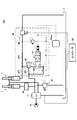
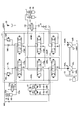
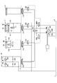
- FIG. 27 is a diagram showing a first example of the characteristic configuration of the shovel 100 according to the present embodiment. Specifically, it is a diagram showing a first example of a configuration centering on a hydraulic circuit that supplies hydraulic fluid to the boom cylinder 7 of the shovel 100 according to the present embodiment.
- a pilot line 27 for transmitting the secondary side pilot pressure from the lever device 26A to the port of the boom direction control valve 17A for supplying the hydraulic fluid to the boom cylinder 7 in the control valve 17 is referred to as a pilot line 27A.
- the hydraulic fluid is discharged to the tank T by branching from between the boom directional control valve 17A in the control valve 17 and the rod side oil chamber and the bottom side oil chamber of the boom cylinder 7
- Bypass oil passages 281 and 282 are provided.
- the bypass oil passage 281 is provided with a solenoid relief valve 33 that discharges the hydraulic oil in the rod side oil chamber of the boom cylinder 7 to T.
- the bypass oil passage 282 is provided with a solenoid relief valve 33 for discharging the hydraulic oil in the bottom side oil chamber of the boom cylinder 7 to the tank T.
- bypass oil passages 281 and 282 and the electromagnetic relief valves 33 and 34 may be provided either inside or outside the control valve 17.
- the various sensors 32 include pressure sensors 32D and 32E that detect the rod pressure PR and the bottom pressure PB of the boom cylinder 7, and the outputs thereof are input to the controller 30.
- the controller 30, that is, the operation correction unit 302 can monitor the rod pressure PR and the bottom pressure PB based on the output signals input from the pressure sensors 32D and 32E. In addition, the operation correction unit 302 appropriately outputs a current command value to the electromagnetic relief valves 33 and 34 to forcibly discharge the hydraulic oil in the rod side oil chamber or the bottom side oil chamber of the boom cylinder 7 to the tank T. Excess pressure in the boom cylinder 7 can be suppressed. Therefore, by employing the correction method for correcting the operation of the boom cylinder 7 described with reference to FIGS. 9 to 17 and reducing the excessive pressure generated in the boom cylinder 7, the unintended operation of the shovel 100, That is, the drag operation and the floating operation can be suppressed.
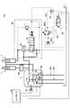
- FIG. 28 is a figure which shows the 2nd example of the characteristic structure of the shovel 100 based on this embodiment. Specifically, it is a diagram showing a second example of the configuration centering on the hydraulic circuit that supplies the hydraulic fluid to the boom cylinder 7 of the shovel 100 according to the present embodiment.
- a solenoid proportional valve 36 is provided in the pilot line 27A between the lever device 26A and the port of the boom direction control valve 17A.
- the various sensors 32 include pressure sensors 32D and 32E that detect the rod pressure PR and the bottom pressure PB of the boom cylinder 7 as in the case of FIG.
- the controller 30, that is, the operation correction unit 302 can monitor the rod pressure PR and the bottom pressure PB based on the output signals input from the pressure sensors 32D and 32E. Further, the operation correction unit 302 appropriately changes the pilot pressure corresponding to the operation state of the lever device 26A by outputting the current command value to the solenoid proportional valve 36, and inputs the pilot pressure to the port of the boom direction control valve 17A. be able to. That is, the operation correction unit 302 appropriately controls the boom direction control valve 17A by outputting the current command value to the solenoid proportional valve 36, and the hydraulic oil of the rod side oil chamber or the bottom side oil chamber of the boom cylinder 7 Can be discharged into the tank T as appropriate to suppress excessive pressure in the boom cylinder 7.
- the operation state of the boom 4 A signal different from the signal to be input may be input.
- an electromagnetic proportional valve may be provided in an oil passage branched from the pilot line 25 on the upstream side (the pilot pump 15 side) of the lever device 46A and connected to the port of the boom direction control valve 17A.
- the operation correction unit 302 outputs a current command to the proportional solenoid valve, thereby inputting a signal different from the signal corresponding to the operation state of the boom 4 to the direction control valve 17A for the boom, and the lever device 26A.
- the boom directional control valve 17A can be controlled regardless of the operation state of the above. Also, in this case, the controller 30 normally outputs the current command to the proportional solenoid valve based on the pressure signal corresponding to the operation state of the lever device 16A detected by the pressure sensor 29, thereby the lever device 16A by the operator The boom directional control valve 17A can be controlled in accordance with the operation state of the above.
- FIG. 29 is a figure which shows the 3rd example of the characteristic structure of the shovel 100 based on this embodiment. Specifically, it is a diagram showing a third example of the configuration centering on the hydraulic circuit that supplies hydraulic fluid to the boom cylinder 7 of the shovel 100 according to the present embodiment.
- the various sensors 32 include pressure sensors 32D and 32E for detecting the rod pressure PR and the bottom pressure PB of the boom cylinder 7 as in the case of FIG. Is input to
- the controller 30, that is, the operation correction unit 302 can monitor the rod pressure PR and the bottom pressure PB based on the output signals input from the pressure sensors 32D and 32E. Further, the controller 30 can control the output and the flow rate of the main pump 14 by appropriately outputting the current command value to the regulator 14A that controls the tilt angle of the swash plate of the main pump 14. That is, the operation correction unit 302 appropriately outputs the current command value to the regulator 14A, and restricts the operation of the main pump 14 to restrict the flow rate of the hydraulic oil supplied to the boom cylinder 7, etc. Excess pressure can be suppressed. Therefore, by employing the correction method for correcting the operation of the boom cylinder 7 described with reference to FIGS. 9 to 17 and reducing the excessive pressure generated in the boom cylinder 7, the unintended operation of the shovel 100, That is, the drag operation and the floating operation can be suppressed.
- FIG. 30 is a figure which shows the 4th example of the characteristic structure of the shovel 100 based on this embodiment. Specifically, it is a diagram showing a fourth example of the configuration centering on the hydraulic circuit that supplies hydraulic fluid to the boom cylinder 7 of the shovel 100 according to the present embodiment.
- the various sensors 32 include pressure sensors 32D and 32E that detect the rod pressure PR and the bottom pressure PB of the boom cylinder 7 as in the case of FIG. Is input to
- the controller 30, that is, the operation correction unit 302 can monitor the rod pressure PR and the bottom pressure PB based on the output signals input from the pressure sensors 32D and 32E.
- the operation correction unit 302 can also control the output of the engine 11 by outputting a control command to an ECM (Engine Control Module) 11A that controls the operating state of the engine 11 as appropriate. That is, the operation correction unit 302 appropriately outputs a control command to the ECM 11A to restrict the output of the engine 11, thereby restricting the output of the main pump 14 driven by the engine 11 and supplied to the boom cylinder 7.
- the flow rate of hydraulic fluid can be limited. That is, the motion correction unit 302 can suppress an excessive pressure in the boom cylinder 7.
- FIG. 31 is a figure which shows the 5th example of the characteristic structure of the shovel 100 based on this embodiment. Specifically, it is a diagram showing a fifth example of the configuration centering on the hydraulic circuit that supplies the hydraulic fluid to the boom cylinder 7 of the shovel 100 according to the present embodiment.
- the various sensors 32 include pressure sensors similar to the pressure sensors 32D and 32E shown in FIGS. The same applies to FIGS. 32 to 35 below.
- control valve 17 includes an electromagnetic switching valve 38.
- a mode in which the electromagnetic switching valve 38 bypasses between the oil passage 311 connecting between the boom direction control valve 17A and the bottom side oil chamber of the boom cylinder 7 and the oil passage 312 circulating the hydraulic oil to the tank T Provided.
- the electromagnetic switching valve 38 when the electromagnetic switching valve 38 is in the communication state, the hydraulic oil in the bottom side oil chamber of the boom cylinder 7 can be discharged to the tank T.
- the controller 30, that is, the operation correction unit 302, outputs the rod pressure PR and the rod pressure PR based on output signals input from the various sensors 32 (pressure sensors for detecting the pressures of the rod side oil chamber and the bottom side oil chamber of the boom cylinder 7). Bottom pressure PB can be monitored. Further, the operation correction unit 302 can control the communication / non-communication state of the electromagnetic switching valve 38 by outputting the current command value to the electromagnetic switching valve 38 as appropriate. That is, the operation correction unit 302 appropriately outputs a current command value to the electromagnetic switching valve 38, and discharges the hydraulic oil in the bottom side oil chamber of the boom cylinder 7 to the tank T via the electromagnetic switching valve 38, The excessive pressure (bottom pressure PB) generated in the bottom side oil chamber of the boom cylinder 7 can be suppressed.
- the various sensors 32 pressure sensors for detecting the pressures of the rod side oil chamber and the bottom side oil chamber of the boom cylinder 7.
- Bottom pressure PB can be monitored.
- the operation correction unit 302 can control the communication / non-communication state of the
- An oil passage connecting between the boom direction control valve 17A and the rod side oil chamber of the boom cylinder 7 and an oil passage 312 circulating the hydraulic oil to the tank T are bypassed inside the control valve 17
- An electromagnetic switching valve may be provided.
- the operation correction unit 302 can appropriately reduce the excess pressure generated in the rod-side oil chamber of the boom cylinder 7 by outputting the current command value to the electromagnetic switching valve.
- FIG. 32 is a figure which shows the 6th example of the characteristic structure of the shovel 100 based on this embodiment. Specifically, it is a diagram showing a fifth example of the configuration centering on the hydraulic circuit that supplies the hydraulic fluid to the boom cylinder 7 of the shovel 100 according to the present embodiment.
- any boom cylinder 7 may be provided in that a control valve 17 and a pressure holding circuit 40 described later are interposed between the main pump 14 and the boom cylinders 7.
- the hydraulic circuit for one of the boom cylinders 7 (the boom cylinder 7 on the right side in the drawing) will be mainly described.
- the pressure holding circuit 40 is interposed in an oil passage connecting the control valve 17 and the bottom side oil chamber of the boom cylinder 7.
- the pressure holding circuit 40 mainly includes a holding valve 42 and a spool valve 44.
- the holding valve 42 supplies the hydraulic oil supplied from the control valve 17 via the oil passage 321 to the bottom side oil chamber of the boom cylinder 7 regardless of the state of the spool valve 44.
- the holding valve 42 prevents the hydraulic oil in the bottom side oil chamber of the boom cylinder 7 from being discharged downstream of the pressure holding circuit 40 Hold.
- the holding valve 42 when the spool valve 44 is in the communicating state (the spool state at the right end in the figure), the hydraulic oil in the bottom side oil chamber of the boom cylinder 7 is in the pressure holding circuit 40 via the oil passage 322. It can be discharged downstream.
- the spool valve 44 is a pilot pressure input to the port from the boom lowering remote control valve 26Aa, which is included in the lever device 26A for operating the boom cylinder 7, and outputs a pilot pressure corresponding to the boom 4 lowering operation (boom lowering operation).
- the communication / non-communication state is controlled accordingly. Specifically, when a pilot pressure indicating that the boom lowering operation is being performed is input from the boom lowering remote control valve 26Aa, the spool valve 44 is in a spool state corresponding to the communication state (a spool state at the right end in the figure ).
- the spool valve 44 enters the spool state (the spool state at the left end in the figure) corresponding to the disconnection state. Do. Thus, even if breakage or the like of the hydraulic hose downstream of the pressure holding circuit 40 occurs in a state where the boom lowering operation is not performed, the hydraulic oil (bottom pressure) of the bottom side oil chamber of the boom cylinder 7 is held. Thus, the boom 4 can be prevented from falling.
- the pressure holding circuit 40 also includes an electromagnetic relief valve 46.
- the electromagnetic relief valve 46 branches from the oil passage 323 between the holding valve 42 in the pressure holding circuit 40 and the bottom side oil chamber of the boom cylinder 7 and is provided in the oil passage 324 connected to the tank T. That is, the electromagnetic relief valve 46 relieves the working oil to the tank T from the oil passage 323 on the upstream side of the holding valve, that is, the boom cylinder 7 side. Therefore, the electromagnetic relief valve 46 discharges the hydraulic oil in the bottom side oil chamber of the boom cylinder 7 to the tank T regardless of the operating state of the pressure holding circuit 40, specifically, the communication / non-communication state of the spool valve 44. It can be done.
- the controller 30, that is, the operation correction unit 302, outputs the rod pressure PR and the rod pressure PR based on output signals input from the various sensors 32 (pressure sensors for detecting the pressures of the rod side oil chamber and the bottom side oil chamber of the boom cylinder 7). Bottom pressure PB can be monitored. Further, the operation correction unit 302 appropriately outputs the current command value to the electromagnetic relief valves 33 and 46 to operate the rod side oil chamber or the bottom side oil chamber of the boom cylinder 7 regardless of the presence or absence of the boom lowering operation. The oil can be forced to be discharged into the tank T to suppress the excessive pressure in the boom cylinder 7. Therefore, by employing the correction method for correcting the operation of the boom cylinder 7 described with reference to FIGS. 9 to 17 and reducing the excessive pressure generated in the boom cylinder 7, the unintended operation of the shovel 100, That is, the drag operation and the floating operation can be suppressed.
- FIG. 33 is a figure which shows the 7th example of the characteristic structure of the shovel 100 based on this embodiment. Specifically, it is a diagram showing a seventh example of the configuration centering on the hydraulic circuit that supplies hydraulic fluid to the boom cylinder 7 of the shovel 100 according to the present embodiment.
- the electromagnetic relief valve 50 is provided in the oil passage 332 branched from the oil passage 331 between the bottom side oil chamber of the boom cylinder 7 and the pressure holding circuit 40 and connected to the tank T.
- the electromagnetic relief valve 50 does not depend on the operating state of the pressure holding circuit 40, specifically, the communication oil state of the bottom side oil chamber of the boom cylinder 7 to the tank T regardless of the communication state of the spool valve 44. It can be discharged. That is, while the fall of the boom 4 is prevented by the holding function of the hydraulic fluid of the bottom side oil chamber of the boom cylinder 7 by the pressure holding circuit 40, the bottom side oil chamber of the boom cylinder 7 is not affected by the operation state of the boom cylinder 7. The hydraulic oil can be discharged to the tank T to suppress an excessive bottom pressure.
- the controller 30, that is, the operation correction unit 302, the rod pressure PR and the bottom based on output signals input from the various sensors 32 (pressure sensors for detecting the pressures of the rod side oil chamber and the bottom side oil chamber of the boom cylinder 7).
- the pressure PB can be monitored.
- the operation correction unit 302 appropriately outputs the current command value to the electromagnetic relief valves 33 and 50 to operate the rod side oil chamber or the bottom side oil chamber of the boom cylinder 7 regardless of the presence or absence of the boom lowering operation.
- the oil can be forced to be discharged into the tank T to suppress the excessive pressure in the boom cylinder 7. Therefore, by employing the correction method for correcting the operation of the boom cylinder 7 described with reference to FIGS. 9 to 17 and reducing the excessive pressure generated in the boom cylinder 7, the unintended operation of the shovel 100, That is, the drag operation and the floating operation can be suppressed.
- FIG. 34 is a figure which shows the 8th example of the characteristic structure of the shovel 100 based on this embodiment. Specifically, it is a view showing an eighth example of the configuration centering on the hydraulic circuit that supplies the hydraulic fluid to the boom cylinder 7 of the shovel 100 according to the present embodiment.
- an electromagnetic switching valve 52 in the pilot circuit for supplying the pilot pressure corresponding to the operation state of the boom lowering operation from the boom lowering remote control valve 26Aa to the spool valve 44 of the pressure holding circuit 40, an electromagnetic switching valve 52, a shuttle valve 54 are provided.
- the electromagnetic switching valve 52 branches from the pilot line 25A between the pilot pump 15 and the boom lowering remote control valve 26Aa, and bypasses the boom lowering remote control valve 26Aa to be connected to one input port of the shuttle valve 54. It is provided in the path 341.
- the electromagnetic switching valve 52 switches the communication / non-communication state of the oil passage 341.
- the communication / non-communication state of the oil passage 341 may be switched by adopting an electromagnetic proportional valve.
- one end of the oil passage 341 is connected to one input port of the shuttle valve 54, and the oil passage 342 on the secondary side of the boom lowering remote control valve 26Aa is connected to the other input port.
- the shuttle valve 54 outputs the higher one of the pilot pressure of the two inputs toward the spool valve 44.
- the same pilot pressure as when the boom lowering operation is performed is input to the spool valve 44 via the electromagnetic switching valve 52 and the shuttle valve 54.
- the hydraulic oil in the bottom side oil chamber of the boom cylinder 7 can be made to flow downstream of the pressure holding circuit 40.
- the electromagnetic relief valves 56 and 58 are provided inside the control valve 17.
- the electromagnetic relief valves 56 and 58 are provided outside the control valve 17 as long as the hydraulic oil can be discharged to the tank T by bypassing the oil passage between the boom direction control valve 17A and the pressure holding circuit 40. It may be done.
- the electromagnetic relief valve 56 branches from the oil passage between the rod side oil chamber of the boom cylinder 7 and the boom direction control valve 17A, and is provided in the oil passage 343 connected to the tank T.
- the solenoid relief valve 56 can discharge the hydraulic oil in the rod side oil chamber of the boom cylinder 7 to the tank T.
- the electromagnetic relief valve 58 branches from the oil passage between the pressure holding circuit 40 and the boom direction control valve 17A, and is provided in an oil passage 344 connected to the tank T.
- the electromagnetic relief valve 56 can discharge the hydraulic oil flowing out of the bottom side oil chamber of the boom cylinder 7 to the tank T via the pressure holding circuit 40. That is, by the action of the electromagnetic switching valve 52 and the shuttle valve 54 described above, the hydraulic relief valve 58 transfers the hydraulic oil of the bottom side oil chamber of the boom cylinder 7 to the tank T even when the boom lowering operation is not performed. It is possible to discharge and suppress the excessive bottom pressure PB.
- the function of the electromagnetic relief valve 58 may be replaced by the electromagnetic switching valve 38.
- the oil passage connecting the boom direction control valve 17A and the rod side oil chamber of the boom cylinder 7 and the oil for circulating the hydraulic oil to the tank T An electromagnetic switching valve may be provided in the control valve 17 to bypass between the passages.
- the function of the electromagnetic relief valve 56 may be replaced by the electromagnetic switching valve.
- the controller 30, that is, the operation correction unit 302, the rod pressure PR and the bottom based on output signals input from the various sensors 32 (pressure sensors for detecting the pressures of the rod side oil chamber and the bottom side oil chamber of the boom cylinder 7).
- the pressure PB can be monitored.
- the operation correction unit 302 appropriately outputs a current command value to the electromagnetic switching valve 52 and the electromagnetic relief valves 56 and 58, so that the rod side oil chamber or the bottom of the boom cylinder 7 can be operated regardless of the boom lowering operation.
- the hydraulic oil in the side oil chamber can be forcibly discharged to the tank T, and excessive pressure in the boom cylinder 7 can be suppressed. Therefore, by employing the correction method for correcting the operation of the boom cylinder 7 described with reference to FIGS. 9 to 17 and reducing the excessive pressure generated in the boom cylinder 7, the unintended operation of the shovel 100, That is, the drag operation and the floating operation can be suppressed.
- FIG. 35 is a figure which shows the 9th example of the characteristic structure of the shovel 100 based on this embodiment. Specifically, it is a diagram showing a ninth example of the configuration focusing on a hydraulic circuit that supplies hydraulic fluid to the boom cylinder 7 of the shovel 100 according to the present embodiment.
- a solenoid proportional valve 60 is used as a pilot circuit for supplying a pilot pressure corresponding to the boom lowering operation state from the boom lowering remote control valve 26Aa to the spool valve 44 of the pressure holding circuit 40;
- a shuttle valve 54 similar to that of FIG. 34 is provided.
- the solenoid proportional valve 60 branches from the pilot line 25A between the pilot pump 15 and the boom lowering remote control valve 26Aa, and bypasses the boom lowering remote control valve 26Aa to be connected to one input port of the shuttle valve 54. It is provided in the passage 351.
- the solenoid proportional valve 60 performs switching control of the communication path 341 in the communication / non-communication state and control of the pilot pressure input to the shuttle valve 54.
- one end of the oil passage 351 is connected to one input port as in the case of FIG. 34, and the oil passage 352 on the secondary side of the boom lowering remote control valve 26Aa is connected to the other input port.
- the shuttle valve 54 outputs the higher one of the pilot pressure of the two inputs toward the spool valve 44. Thereby, even when the boom lowering operation is not performed, the same pilot pressure as when the boom lowering operation is performed is input to the spool valve 44 via the solenoid proportional valve 60 and the shuttle valve 54. Can. That is, even when the boom lowering operation is not performed, the hydraulic oil in the bottom side oil chamber of the boom cylinder 7 can be made to flow downstream of the pressure holding circuit 40.
- the electromagnetic relief valve 56 is provided inside the control valve 17.
- the electromagnetic relief valve 56 is provided outside the control valve 17 as long as the hydraulic oil can be discharged to the tank T by bypassing the oil passage between the boom direction control valve 17A and the pressure holding circuit 40. It is also good.
- the electromagnetic relief valve 56 is provided in an oil passage 353 which is branched from the oil passage between the rod side oil chamber of the boom cylinder 7 and the boom direction control valve 17A and is connected to the tank T as in the case of FIG. Be Thus, the solenoid relief valve 56 can discharge the hydraulic oil in the rod side oil chamber of the boom cylinder 7 to the tank T.
- the controller 30, that is, the operation correction unit 302, the rod pressure PR and the bottom based on output signals input from the various sensors 32 (pressure sensors for detecting the pressures of the rod side oil chamber and the bottom side oil chamber of the boom cylinder 7).
- the pressure PB can be monitored.
- the operation correction unit 302 appropriately discharges the hydraulic oil in the rod side oil chamber of the boom cylinder 7 to the tank T by outputting the current command value to the electromagnetic relief valve 56, and the rod of the boom cylinder 7 It is possible to suppress an excessive pressure (rod pressure) in the side oil chamber.
- the controller 30 appropriately outputs the current command value to the solenoid proportional valve 60, and finely controls the operating state of the solenoid proportional valve 60, so that the bottom side oil of the boom cylinder 7 via the pressure holding circuit 40.
- the flow rate of the hydraulic fluid flowing out of the chamber can be finely adjusted. That is, the controller 30 can adjust the flow rate of the hydraulic fluid discharged from the bottom side oil chamber of the boom cylinder 7 via the control valve 17 during the boom lowering operation, regardless of the control valve 17.
- the controller 30, that is, the operation correction unit 302 appropriately outputs the current command value to the solenoid proportional valve 60, so that the hydraulic oil in the bottom side oil chamber of the boom cylinder 7 is output regardless of the boom lowering operation.
- the tank T can be appropriately discharged to suppress excessive pressure in the boom cylinder 7.
- FIG. 36 is a flowchart schematically showing an example of the operation correction process by the controller 30 according to the present embodiment. The process according to this flowchart is repeatedly performed, for example, at predetermined time intervals while the shovel 100 is in operation.
- step S3600 the operation determination unit 301 determines whether the shovel 100 is traveling based on the inputs from the pressure sensor 29 and the various sensors 32. The operation determination unit 301 proceeds to step S3602 when the shovel 100 is not traveling, and ends the current process when the shovel 100 is traveling.
- step S 3602 the operation determination unit 301 determines whether the attachment is being operated based on the input from the pressure sensor 29 or the various sensors 32, that is, whether it is during work using the attachment (during excavating work) It is determined whether or not.
- the operation determination unit 301 proceeds to step S3604 when the attachment is being operated, and ends the current process when the attachment is not being operated.
- step S3604 the operation determination unit 301 determines whether an unintended operation has occurred based on the input of the various sensors 32. At this time, the operation determination unit 301 targets all or part of the above-described unintended operation, and determines whether or not the unintended operation is generated using the above-described determination method. If an unintended operation has occurred, the operation determining unit 301 proceeds to step S3606, and if an unintended operation has not occurred, the current process ends.
- step S3606 the operation correction unit 302 acquires a control target value that matches the generated operation (determination operation). For example, when it is determined that the vibration operation is occurring, the motion correction unit 302 acquires the limited thrust FMAX or the held thrust FMIN as the control target value based on the content described with reference to FIG. 18 described above. . Further, also for the unintended operations other than the vibration operation, that is, in the case of the dragging operation and the floating operation, the operation correcting unit 302 sets the control target value as the control target value based on the table reference as in the contents described with reference to FIG. You may get a limit thrust of.
- step S3608 the operation correction unit 302 outputs a control command to the control target to correct the operation of the attachment.
- the electromagnetic relief valves 33 and 34, the proportional solenoid valve 36, the regulator 14A, the ECM 11A, the electromagnetic switching valve 38, the electromagnetic relief valve 46, the electromagnetic relief valve 50, the electromagnetic switching valve 52, and the electromagnetic relief The valves 56 and 58, the solenoid proportional valve 60 and the like are included.
- Patent Document 1 discloses a technology for suppressing unintended operations such as dragging operation and lifting operation of a shovel by hydraulic control such that the pressure of a hydraulic cylinder driving an attachment of the shovel is equal to or less than a predetermined allowable maximum pressure. It is done.
- Patent Document 1 the operation of the attachment of the shovel is corrected without determining whether or not the unintended operation has actually occurred, which may deteriorate the operability of the operator.
- the operation determination unit 301 determines the occurrence of an unintended operation. Then, the motion correction unit 302 corrects the motion of the attachment when the motion determination unit 301 determines the occurrence of an unintended motion. As a result, after confirming that the unintended operation has actually occurred, the operation of the attachment is corrected, so that it is possible to suppress the deterioration of the operability by the operator while suppressing the unintended operation.
- the traveling body A swing body mounted rotatably on the traveling body; And an attachment mounted on the rotating body.
- a detection unit attached to the rotating body or the attachment, for detecting a relative positional relationship between one of the rotating body and the attachment, which is an attachment target, and a peripheral object;
- a determination unit that determines whether or not a predetermined unintended operation has occurred based on a change in the relative positional relationship between the attachment object and the fixed reference object around the shovel, which is detected by the detection unit; , Further comprising, Excavator.
- the detection unit detects a relative positional relationship between the attachment object and the ground around the shovel as the reference object.
- the shovel as described in (1-1).
- the detection unit is attached to the rotating body.
- the shovel as described in (1-1) or (1-2).
- the determination unit determines that the floating operation has occurred as the unintended operation when the relative position of the reference object seen from the attachment detected by the detection unit moves in the vertical direction.
- the shovel as described in (1-3) or (1-4).
- the detection unit is attached to the attachment and detects a relative positional relationship between the attachment and each of the reference object and the rotating body, The determination unit performs the unintended operation based on a change in the relative position of the reference object seen from the attachment and a change in the relative position of the swing body seen from the attachment, detected by the detection unit. To determine if has occurred, The shovel as described in (1-1) or (1-2).
- the motion correction unit operates the attachment when the determination unit determines that the unintended operation has occurred in a state where the traveling body is not operated and the attachment is operated. To correct The shovel as described in (1-7).
- the traveling body A swing body mounted rotatably on the traveling body; And an attachment mounted on the rotating body.
- the shovel further includes a determination unit that determines whether a predetermined unintended operation has occurred in the shovel. Excavator.
- the determination unit determines whether the unintended operation has occurred based on the output of the sensor.
- the shovel as described in (2-1) or (2-2).
- the sensor includes a first sensor attached to a boom of the attachment to detect movement of the boom;
- the determination unit determines whether the unintended operation has occurred based on a change in the output of the first sensor.
- the shovel as described in (2-5).
- the sensor includes a second sensor provided on a bucket of the attachment for detecting its movement, and a third sensor provided on at least one of the boom and the arm for detecting its movement.
- the determination unit determines whether or not the unintended operation has occurred based on a change in the relative relationship between the output of the second sensor and the output of the third sensor.
- the motion correction unit operates the attachment when the determination unit determines that the unintended operation has occurred in a state where the traveling body is not operated and the attachment is operated. To correct The shovel as described in (2-8).
- the traveling body A swing body mounted rotatably on the traveling body; An attachment mounted on the rotating body; A hydraulic actuator for driving the attachment; A hydraulic control unit that controls the hydraulic pressure of the hydraulic actuator in relation to the operation of the attachment, the hydraulic control unit being capable of controlling the hydraulic pressure of the hydraulic actuator regardless of the operating state of the attachment; Excavator.
- (3-2) It further comprises a control valve that controls the operation of the hydraulic actuator according to the operation by the operator.
- the hydraulic control unit controls the hydraulic pressure of the hydraulic actuator by discharging hydraulic oil to a tank from an oil passage between the control valve and the hydraulic actuator.
- the shovel as described in (3-1).
- the hydraulic circuit further comprises a holding valve provided in an oil passage between the control valve and the hydraulic actuator and holding hydraulic fluid of the hydraulic actuator.
- the hydraulic control unit controls the hydraulic pressure of the hydraulic actuator by discharging hydraulic oil to a tank from an oil passage between the hydraulic actuator and the holding valve. The shovel described in (3-2).
- the hydraulic control unit is configured to input a signal obtained by correcting a signal corresponding to the operation state of the attachment or a signal different from a signal corresponding to the operation state of the attachment to the control valve, thereby Control oil pressure, The shovel as described in (3-1).
- (3-5) It further comprises a hydraulic pump driven by a predetermined power source and supplying hydraulic fluid to the hydraulic actuator,
- the hydraulic control unit controls the hydraulic pressure of the hydraulic actuator by controlling the hydraulic pump or the power source.
- a control valve that controls the operation of the hydraulic actuator according to an operation by an operator;
- a holding valve provided in an oil passage between the control valve and the hydraulic actuator, for holding hydraulic oil of the hydraulic actuator;
- a holding release unit configured to release holding of the hydraulic oil of the hydraulic actuator by the holding valve in accordance with the operation state of the attachment.
- the hydraulic control unit controls the pressure of the hydraulic actuator by controlling the holding and releasing unit and releasing the holding of the hydraulic oil by the holding valve regardless of the operation state of the attachment.
- a determination unit that determines whether a predetermined unintended operation of the shovel has occurred;
- the operation control unit further includes an operation correction unit that corrects the operation of the attachment using the hydraulic pressure control unit when the determination unit determines that the unintended operation has occurred.
- the shovel according to any one of (3-1) to (3-6).
- the motion correction unit operates the attachment when the determination unit determines that the unintended operation has occurred in a state where the traveling body is not operated and the attachment is operated. To correct The shovel as described in (3-7).
- a configuration capable of mainly discharging the hydraulic oil of both the rod side oil chamber and the bottom side oil chamber of the boom cylinder 7 to the tank T
- either one of the hydraulic oil may be discharged to the tank T.
- a configuration capable of discharging the hydraulic oil of only the oil chamber to the tank T may be employed.
- the operation of the boom cylinder 7 of the attachment (specifically, the pressure of the boom cylinder 7) is mainly corrected, but it goes without saying that the arm cylinder 8 and the bucket cylinder 9 The operation may be controlled.
- FIGS. 37 and 38 a specific example of correcting the operation of arm cylinder 8 will be described.
- FIG. 37 and 38 are diagrams for explaining a first modified example of the shovel 100.
- FIG. Specifically, FIG. 37 is an operation waveform diagram regarding the dragging operation of the shovel 100.
- the velocity v of the lower traveling body 1 along the straight line L1 corresponding to the direction in which the attachment extends from above, the acceleration ⁇ of the lower traveling body 1 along the straight line L1, and the motion axis generated in the attachment The moment ⁇ (for example, the moment ⁇ 2 about the movement axis of the arm 5 shown in FIG. 38) and the force F3 along the straight line L1 exerted on the body of the shovel 100 by the movement of the attachment are shown.
- FIG. 38 is a view showing an example of a mechanical model corresponding to the digging operation by the shovel 100, and exemplarily shows a force acting on the shovel 100 at the time of the digging operation.
- FIG. 37 an operation waveform when correction of the operation of the attachment is not performed is shown by an alternate long and short dash line.
- the operation determination unit 301 determines the occurrence of the drag operation based on, for example, the acceleration ⁇ detected by the above-described acceleration sensor 32A. For example, when the acceleration ⁇ detected by the acceleration sensor 32A exceeds a predetermined threshold value ⁇ TH, the operation determination unit 301 determines that the drag operation has occurred. Then, when the determination is performed by the operation determination unit 301, correction control of the operation of the attachment by the operation correction unit 302 becomes effective (see FIG. 36).
- the acceleration ⁇ exceeds the threshold ⁇ TH, whereby the correction control by the operation correction unit 302 becomes effective.
- the correction control is effective during the correction period T, and in the correction period T, the operation correction unit 302 reduces the moment ⁇ 2 about the operation axis of the arm 5 regardless of the operation state by the operator.
- the moment ⁇ 2 decreases, the force F3 exerted on the body of the shovel 100 by the attachment decreases.
- the force F3 falls below the dynamic friction force ⁇ ′N, the dragging operation is settled.
- the correction period T may be about 1 millisecond to 2 seconds, and preferably about 10 ms to 200 ms in consideration of simulation results by the present inventors.
- the force F After canceling the correction, the force F also increases to the original level, but since the lower traveling body 1 is at rest with respect to the ground, it remains stationary as long as the force F does not exceed the maximum static friction force ⁇ N. There is no occurrence of dragging again.
- the motion correction unit 302 instantaneously reduces the pressure of the arm cylinder 8 according to the determination result by the motion determination unit 301, and limits the thrust, whereby the pulling force of the arm 5, that is, the moment ⁇ 2 Reduce.
- the force F3 applied from the attachment to the vehicle body (upper swing body 3) is reduced, and the dynamic friction force ⁇ 'N is less than that, and the dragging operation of the shovel 100 is stopped.
- the correction control by the operation correction unit 302 is released, and the moment ⁇ 2 of the arm 5 is returned to the original, that is, the moment ⁇ 2 according to the operation state by the operator is returned.
- the maximum static friction force ⁇ N > ⁇ ′N
- no drag operation occurs. This process is periodically repeated at a very short time interval, so that a drag operation can be performed without requesting a change in the operation amount of the control lever by the operator and without impairing the operation feeling (operability) by the operator. It can be suppressed.
- the operation of the attachment other than the boom cylinder 7 may be corrected to suppress an unintended operation.
- the operation of the attachment is corrected in a mode in which the pressure of the boom cylinder 7 or the like is suppressed and the thrust is limited, but the operation of the attachment may be corrected in another mode.
- a method of correcting the operation of the attachment in a mode in which at least one of the attachments is displaced to finely adjust the posture of the attachment will be described.
- FIG. 39 is a view for explaining a second modification of the shovel 100.
- FIG. Specifically, FIG. 39 is a view for explaining a method of correcting the attachment according to another aspect.
- FIG. 39 shows the shovel 100 during the digging operation viewed from the side.
- the state of the attachment before the correction of the movement is indicated by a solid line, and the state of the attachment after the correction of the movement is indicated by an alternate long and short dash line.
- the motion correction unit 302 corrects the motion of the attachment, and when the posture of the attachment changes, the direction of the moment (force) acting on the root 3A changes from T to Ta. As one example, in FIG. 39, the motion correction unit 302 corrects the position of the boom 4 from the solid line to the alternate long and short dash line 4a.
- the component (force to drag the lower traveling body 1) Fa parallel to the ground in the moment Ta after correction is smaller than the force F3 before correction. Thereby, the dragging operation of the shovel 100 is suppressed.
- the main correction is realized by operating the arm cylinder 8 in the contraction direction (that is, the direction in which the arm 5 is lowered) regardless of the operation state by the operator. More specifically, for example, the motion correction unit 302 may output a current command value for moving the arm cylinder 8 in the contraction direction to the solenoid proportional valve of FIG.
- the drag operation is suppressed by the two actions of reducing the force F3 affecting the drag action and increasing the vertical drag force N, but an embodiment using only one of the actions is also effective. It is.
- the operation of the attachment may be corrected to suppress an unintended operation.
- the operation of the attachment is corrected when it is determined that an unintended operation has occurred, but the unintended operation is suppressed regardless of the occurrence of an unintended operation.
- the operation of the attachment may be corrected.
- a method of correcting the operation of the attachment will be described so as to suppress the unintended operation regardless of the occurrence of the unintended operation while exemplifying the case of the vibrating operation.
- FIG. 40 is a view for explaining a third modification of the shovel 100. As shown in FIG. Specifically, it is a flowchart schematically showing an example of suppression processing of the vibration operation by the operation correction unit 302. The process according to this flowchart is repeatedly performed, for example, at predetermined time intervals while the shovel 100 is in operation.
- step S4000 the operation determination unit 301 determines whether or not the air operation is in progress. If it is determined that the air movement is in progress, the operation determination unit 301 proceeds to step S4002. If it is determined that the air movement is not in progress, the current process ends.
- step S4002 the operation correction unit 302 monitors the state of the attachment (for example, the boom angle ⁇ 1, the arm angle ⁇ 2, the bucket angle ⁇ 3, and the like).
- step S4004 the operation correction unit 302 determines, for example, the limit thrust FMAX according to the state of the attachment (see FIG. 18).
- step S4006 operation correction unit 302 determines holding thrust FMIN according to the state of the attachment (see FIG. 18).
- step S4008 operation correction unit 302 sets limit thrust FMAX and holding thrust F. Based on MIN, the upper limit PMAX of the bottom pressure of the cylinder to be controlled (for example, the boom cylinder 7) is determined (see FIG. 30).
- the motion correction unit 302 may limit the thrust of the cylinder and suppress the vibration operation regardless of the occurrence of the vibration operation. Further, the same applies to other unintended operations, that is, suppression of the dragging operation and the floating operation, and the operation correcting unit 302 corrects the above-described correction method regardless of the occurrence of the unintended operation (FIGS. 18) may be performed to suppress unintended operation.
- the hydraulic oil in the rod side oil chamber or the bottom side oil chamber of the cylinder to be controlled (for example, the boom cylinder 7) is discharged to the tank in order to suppress unintended operation of the shovel 100. , May be played.
- an unintended operation for example, a dragging operation or a floating operation
- FIGS. 41 to 49 an unintended operation (for example, a dragging operation or a floating operation) can be performed by regenerating the hydraulic oil between the rod side oil chamber and the bottom side oil chamber of the control target cylinder. A method of suppressing will be described.
- FIG. 41 is a diagram showing a configuration example of a drive system mounted on a shovel according to a fourth modification.
- the mechanical power system is indicated by a double line
- the hydraulic oil line is indicated by a thick solid line
- the pilot line is indicated by a broken line
- the electrical control system is indicated by an alternate long and short dash line.
- the main pump 14 and the pilot pump 15 are connected to the output shaft of the engine 11.
- the main pump 14 is a variable displacement hydraulic pump whose discharge amount per rotation is controlled by the regulator 14A.
- the pilot pump 15 is a fixed displacement hydraulic pump.
- a control valve 17 is connected to the main pump 14 via a hydraulic fluid line 16.
- An operating device 26 is connected to the pilot pump 15 via a pilot line 25.
- the control valve 17 is a valve set including a plurality of valves as described above, and controls the hydraulic system in the shovel.
- the control valve 17 is connected to hydraulic actuators such as the traveling hydraulic motor 1L, the traveling hydraulic motor 1R, the boom cylinder 7, the arm cylinder 8, the bucket cylinder 9, and the swing hydraulic motor 21 via a hydraulic fluid line.
- the operating device 26 is a device for operating the hydraulic actuator as described above, and includes an operating lever and an operating pedal.
- the operating device 26 is connected to the control valve 17 via a pilot line 27 and to the pressure sensor 29 via a pilot line 28.
- the pressure sensor 29 detects the pilot pressure generated by the operating device 26 and transmits information on the detected pilot pressure to the controller 30.
- the pressure sensor 29 includes an arm operating pressure sensor that detects the operating state of the arm operating lever, and a boom operating pressure sensor that detects the operating state of the boom operating lever.
- the controller 30 is a control device as a main control unit that performs drive control of the shovel as described above.
- the controller 30 is composed of an arithmetic processing unit including a CPU and an internal memory, and causes the CPU to execute a drive control program stored in the internal memory to realize various functions.
- the cylinder pressure sensor 32F is included in an example of the various sensors 32 described above, that is, the various sensors 32. Specifically, the cylinder pressure sensor 32F is a sensor that detects the pressure of the hydraulic oil in the oil chamber of the hydraulic cylinder, and outputs the detected value to the controller 30.
- the cylinder pressure sensor 32F includes an arm rod pressure sensor, a boom rod pressure sensor, an arm bottom pressure sensor, a boom bottom pressure sensor, and the like.
- the arm rod pressure sensor detects an arm rod pressure which is the pressure of the hydraulic fluid in the rod side oil chamber 8R of the arm cylinder 8.
- the boom rod pressure sensor detects a boom rod pressure which is a pressure of hydraulic fluid in the rod side oil chamber 7R of the boom cylinder 7.
- the arm bottom pressure sensor detects an arm bottom pressure which is the pressure of the hydraulic oil in the bottom side oil chamber 8B of the arm cylinder 8.
- the boom bottom pressure sensor detects a boom bottom pressure which is the pressure of the hydraulic fluid in the bottom side oil chamber 7B of the boom cylinder 7.
- the posture sensor 32F is included in an example of the various sensors 32 described above, that is, the various sensors 32.
- the posture sensor 32G is a sensor that detects the posture of the shovel, and outputs the detected value to the controller 30.
- the attitude sensor 32G includes an arm angle sensor, a boom angle sensor, a bucket angle sensor, a turning angle sensor, an inclination angle sensor, and the like.
- the arm angle sensor detects an open / close angle of the arm 5 with respect to the boom 4 (hereinafter referred to as “arm angle”).
- the boom angle sensor detects an elevation angle (hereinafter, referred to as “boom angle”) of the boom 4 with respect to the upper swing body 3.
- the bucket angle sensor detects an open / close angle of the bucket 6 with respect to the arm 5 (hereinafter referred to as “bucket angle”).
- Bucket angle an open / close angle of the bucket 6 with respect to the arm 5
- Each of the arm angle sensor, the boom angle sensor, and the bucket angle sensor is configured by, for example, a combination of an acceleration sensor and a gyro sensor. It may be configured by a potentiometer, a stroke sensor, a rotary encoder or the like.
- the turning angle sensor detects the turning angle of the upper swing body 3 with respect to the lower traveling body 1.
- the tilt angle sensor detects a body tilt angle which is the angle of the ground surface of the shovel with respect to the horizontal plane.
- the display device DD is a device for displaying various types of information, and is, for example, a liquid crystal display installed in a cab of a shovel.
- the display device DD displays various information in accordance with the control signal from the controller 30.
- the voice output device AD is a device for voice output of various information, and is, for example, a speaker installed in a cab of a shovel.
- the voice output device AD voice-outputs various information in accordance with the control signal from the controller 30.
- the regeneration valve V1 is disposed in a first oil passage C1 connecting the rod side oil chamber and the bottom side oil chamber of the hydraulic cylinder. That is, the regeneration valve V1 is disposed between the flow rate control valve for adjusting the flow rate of hydraulic fluid to the hydraulic cylinder and the hydraulic cylinder.
- the regeneration valve V1 is, for example, an electromagnetic proportional valve, and controls the flow passage area of the first oil passage C1 in accordance with the control current from the controller 30.
- the regeneration valve V1 includes a boom regeneration valve, an arm regeneration valve, and the like.
- the regeneration valve V1 is a boom regeneration valve disposed in a first oil passage C1 connecting the rod side oil chamber 7R of the boom cylinder 7 and the bottom side oil chamber 7B.
- the regeneration valve V1 allows bidirectional flow of hydraulic fluid between the rod side oil chamber 7R and the bottom side oil chamber 7B. That is, it does not include a check valve. However, from the bottom side oil chamber 7B to the first valve position including the oil passage in which the check valve which allows only the flow of the hydraulic oil from the rod side oil chamber 7R to the bottom side oil chamber 7B is disposed. A second valve position including an oil passage provided with a check valve that allows only the flow of hydraulic oil to rod side oil chamber 7R, and the flow of hydraulic oil between rod side oil chamber 7R and bottom side oil chamber 7B And a third valve position for blocking the valve.
- the regeneration valve V1 has a first proportional valve including two valve positions, a valve position corresponding to the first valve position and a valve position corresponding to the third valve position, and a valve position corresponding to the second valve position It may consist of a second proportional valve including two valve positions of the valve position corresponding to the third valve position. Further, the regeneration valve V1 is disposed outside the control valve 17. Therefore, the movement of the spool valve in the control valve 17 is controlled independently.
- the controller 30 obtains outputs of the pressure sensor 29, the cylinder pressure sensor 32F, the attitude sensor 32G, and the like, and executes calculations by various functional elements.
- the various functional elements include a digging operation detection unit 302A, a posture detection unit 302B, an allowable maximum pressure calculation unit 302C, a regeneration valve control unit 302D, and the like as detailed functional elements of the operation correction unit 302 described above.
- the various functional elements may be configured by software or hardware. Then, the controller 30 outputs the calculation result to the display device DD, the sound output device AD, the reproduction valve V1, and the like.
- the digging operation detection unit 302A is a functional element that detects that a digging operation has been performed.
- the digging operation detection unit 302A detects that an arm digging operation including an arm closing operation has been performed.
- the boom rod pressure is equal to or higher than a predetermined value
- the pressure difference between the arm bottom pressure and the arm rod pressure is equal to or higher than a predetermined value.
- the arm digging operation includes a single operation of only the arm closing operation, a combined operation which is a combination of the arm closing operation and the boom lowering operation, and a combined operation which is a combination of the arm closing operation and the bucket closing operation.
- the digging operation detection unit 302A may detect whether a boom raising combined digging operation including a boom raising operation has been performed. Specifically, when the boom raising operation is detected, the digging operation detection unit 302A detects that the boom rod pressure is equal to or more than a predetermined value, and the pressure difference between the arm bottom pressure and the arm rod pressure is equal to or more than a predetermined value. Raise and detect that a combined drilling operation has been performed. In addition, the digging operation detection unit 302A may detect that the boom raising combined digging operation has been performed, as an additional condition that the arm closing operation is detected.
- the digging operation detection unit 302A detects whether the digging operation has been performed using the output of another sensor such as the posture sensor 32G in addition to or instead of the outputs of the pressure sensor 29 and the cylinder pressure sensor 32F. May be
- the posture detection unit 302B is a functional element that detects the posture of the shovel.
- the posture detection unit 302B detects the boom angle, the arm angle, the bucket angle, the machine body inclination angle, and the turning angle as the posture of the shovel based on the output of the posture sensor 32G.
- the allowable maximum pressure calculation unit 302C is a functional element that calculates the allowable maximum pressure of the hydraulic oil in the hydraulic cylinder during the digging operation.
- the allowable maximum pressure changes according to the posture of the shovel. If the hydraulic oil in the hydraulic cylinder exceeds the maximum allowable pressure during the drilling operation, the shovel's airframe may cause an unintended movement. Unintended movement includes lifting of the airframe, dragging of the airframe, and the like.
- the allowable maximum pressure calculation unit 302C calculates the allowable maximum boom rod pressure during the digging operation. If the boom rod pressure exceeds the maximum allowable boom rod pressure, the shovel's fuselage may lift up.
- the allowable maximum pressure calculation unit 302C may calculate the allowable maximum arm bottom pressure during the digging operation. If the arm bottom pressure exceeds the maximum allowable arm bottom pressure, the shovel's airframe may be dragged towards the digging point.
- the regeneration valve control unit 302D is a functional element that controls the regeneration valve V1 in order to prevent an unintended movement of the airframe of the shovel during the digging operation.
- the regeneration valve control unit 302D adjusts the opening area of the regeneration valve V1 to control the boom rod pressure to be equal to or less than the allowable maximum boom rod pressure in order to prevent the floating of the machine body of the shovel.
- the regeneration valve control unit 302D controls the regeneration valve V1 when it determines that a predetermined condition (hereinafter referred to as "control start condition") regarding the stability of the body of the shovel is satisfied. Prevent the unintended movement of the excavator's fuselage.
- the regeneration valve control unit 302D raises the boom rod pressure to a predetermined pressure less than the allowable maximum boom rod pressure. When reached, it is determined that the control start condition is satisfied. Then, the regeneration valve V1 is opened to increase the opening area of the regeneration valve V1. As a result, hydraulic fluid flows from the rod side oil chamber 7R to the bottom side oil chamber 7B, and the boom rod pressure decreases. At this time, the volume of the bottom side oil chamber 7B increases, and the boom cylinder 7 extends. Thus, by reducing the boom rod pressure, the regeneration valve control unit 302D prevents the boom rod pressure from exceeding the allowable maximum boom rod pressure and prevents the excavator body from rising.
- the regeneration valve control unit 302D may output a control signal to at least one of the display device DD and the sound output device AD.
- a text message indicating that the reproduction valve V1 has been opened is displayed on the display device DD, or a voice message indicating that effect, an alarm sound or the like is output from the voice output device AD.
- FIG. 42 is a diagram showing the relationship of the force acting on the shovel when the excavation is performed.
- control parameters for preventing lifting of the airframe during the drilling operation will be described.
- a point P1 indicates a connection point between the upper swing body 3 and the boom 4
- a point P2 indicates a connection point between the upper swing body 3 and the cylinder of the boom cylinder 7.
- a point P3 indicates a connection point between the rod 7C of the boom cylinder 7 and the boom 4
- a point P4 indicates a connection point between the boom 4 and the cylinder of the arm cylinder 8.
- a point P5 indicates a connection point between the rod 8C of the arm cylinder 8 and the arm 5
- a point P6 indicates a connection point between the boom 4 and the arm 5.
- a point P7 indicates a connection point between the arm 5 and the bucket 6, and a point P8 indicates the tip of the bucket 6.
- FIG. 42 omits illustration of the bucket cylinder 9 for the sake of clarity of the description.
- an angle between a straight line connecting point P1 and point P3 and a horizontal line is boom angle ⁇ 1
- an angle between a straight line connecting point P3 and point P6 and a straight line connecting point P6 and point P7 is An arm angle ⁇ 2 is shown
- an angle between a straight line connecting the points P6 and P7 and a straight line connecting the points P7 and P8 is shown as a bucket angle ⁇ 3.
- the distance D1 is the horizontal distance between the rotation center RC when the floating of the airframe occurs and the gravity center GC of the shovel, ie, the product of the mass M of the shovel and the gravity acceleration g.
- the distance between the line of action of g and the center of rotation RC is shown.
- the product of the distance D1 and the magnitude of the gravity M ⁇ g represents the magnitude of the moment of the first force around the rotation center RC.
- the symbol “ ⁇ ” represents “x” (multiplication symbol).
- the distance D2 is the horizontal distance between the rotational center RC and the point P8, that is, the distance between the line of action of the vertical component F R1 drilling reaction force F R and the rotation center RC.
- the product of the distance D2 and the magnitude of the vertical component FR1 represents the magnitude of the moment of the second force around the rotation center RC.
- excavation reaction force F R is the drilling angle ⁇ formed relative to a vertical axis
- the digging angle ⁇ is calculated based on the boom angle ⁇ 1, the arm angle ⁇ 2, and the bucket angle ⁇ 3.
- the distance D3 is the distance between the straight line and the rotation center RC connecting the points P2 and the point P3, that is, the line of action of the force F B to be Daso pull rod 7C of the boom cylinder 7 rotates Indicates the distance to the center RC.
- the product of the distance D3 and the magnitude of the force F B represents the magnitude of the moment of the third force around the rotation center RC.
- the distance D4 represents the distance between the action line and the point P6 of the excavation reaction force F R.
- the product of the distance D4 and the magnitude of the digging reaction force F R represents the magnitude of the moment of the first force around the point P6.
- the distance D5 indicates the distance between the straight line connecting the points P4 and P5 and the point P6, that is, the distance between the action line of the arm thrust F A closing the arm 5 and the point P6.
- the product of the distance D5 and the magnitude of the arm thrust F A represents the magnitude of the moment of the second force around the point P6.
- the magnitude of the moment of force tending float the excavator vertical component F R1 is the rotation center RC about the excavation reaction force F R, the force F B to be Daso pull rod 7C of the boom cylinder 7 rotates It is assumed that it is possible to replace the magnitude of the moment of force trying to lift the shovel around the center RC.
- the relationship between the magnitude of the moment of the second force around the rotation center RC and the magnitude of the moment of the third force around the rotation center RC is expressed by the following equation (1).
- the size of the excavation reaction force F R is the force to open the arm 5 around the point P6 moment It is considered to be a thing.
- the relationship between the magnitude of the moment of the first force around the point P6 and the magnitude of the moment of the second force around the point P6 is expressed by the following equations (32) and (32) '.
- the symbol “/” represents “ ⁇ ” (division symbol).
- first permissible maximum pressure P BMAX
- P BMAX P BMAX
- the distance D1 is a constant
- the distances D2 to D5 are values determined in accordance with the posture of the digging attachment, ie, the boom angle ⁇ 1, the arm angle ⁇ 2, and the bucket angle ⁇ 3, as with the digging angle ⁇ .
- the distance D2 is determined according to the boom angle ⁇ 1, the arm angle ⁇ 2, and the bucket angle ⁇ 3, the distance D3 is determined according to the boom angle ⁇ 1, and the distance D4 is determined according to the bucket angle ⁇ 3.
- the distance D5 is determined according to the arm angle ⁇ 2.
- the allowable maximum pressure calculation unit 302C can calculate the first allowable maximum pressure PBMAX using the boom angle ⁇ 1 detected by the posture detection unit 302B and the equation (36).
- the regeneration valve control unit 302D can prevent floating of the excavator body by maintaining the boom rod pressure P B in the first permissible maximum pressure P BMAX following a predetermined pressure. Specifically, the regeneration valve control unit 302D, when the boom rod pressure P B reaches a predetermined pressure, to increase the flow rate of the hydraulic fluid flowing out to the bottom-side oil chamber 7B of the rod side oil chamber 7R, boom rod lowering the pressure P B.
- the reduction of the boom rod pressure P B results in the reduction of the arm thrust F A as the equation (34) ′ shows, and further, the reduction of the digging reaction force F R as the equation (32) ′ shows. This is because the vertical component F R1 is reduced.
- the position of the rotation center RC is determined based on the output of the turning angle sensor 32D. For example, when the turning angle between the lower traveling body 1 and the upper swing body 3 is 0 degree, the rear end of the portion where the lower traveling body 1 contacts the ground contact surface becomes the rotation center RC, and the lower traveling body When the turning angle between 1 and the upper swing body 3 is 180 degrees, the front end of the portion where the lower running body 1 contacts the ground contact surface is the rotation center RC. Further, when the turning angle between the lower traveling body 1 and the upper swing body 3 is 90 degrees or 270 degrees, the side end of the portion where the lower traveling body 1 contacts the ground contact surface becomes the rotation center RC. .
- control parameters for preventing the airframe from being dragged toward the digging point during the digging operation will be described.
- the coefficient of static friction ⁇ represents the coefficient of static friction of the ground contact surface of the shovel
- the normal force N represents the normal force against the gravity M ⁇ g of the shovel
- the force F R2 dragged the shovel toward the digging point It represents a horizontal component F R2 of the excavation reaction force F R to wax.
- the friction force ⁇ ⁇ N represents the maximum static friction force to make the shovel stand still, and when the horizontal component F R2 of the digging reaction force F R exceeds the maximum static friction force ⁇ ⁇ N, the shovel is the digging point Are dragged to the side.
- the static friction coefficient ⁇ may be a value stored in advance in a ROM or the like, or may be dynamically calculated based on various information.
- the static friction coefficient ⁇ is a pre-stored value selected by the operator via an input device (not shown). The operator selects a desired friction state (static friction coefficient) from a plurality of friction states (static friction coefficients) in accordance with the condition of the ground contact surface.
- the circular pressure receiving area of the piston facing the bottom side oil chamber 8B of the arm cylinder 8 is an area AA, and the pressure of the hydraulic oil in the bottom side oil chamber 8B is and the arm bottom pressure P a, the circular pressure-receiving area of the piston facing the rod side oil chamber 8R of the arm cylinder 8 and the area a A2, when the pressure of the hydraulic oil in the rod side oil chamber 8R and arm rod pressure P A2,
- P A >> P A 2
- Equation (39) the arm bottom pressure P A of when the left and right sides are equal, aircraft avoidable allowable maximum arm bottom pressure from being dragged towards the drilling site, i.e., more aircraft of drilling site
- the maximum allowable arm bottom pressure (hereinafter referred to as “the second allowable maximum pressure”) PAMAX used to prevent being dragged.
- the allowable maximum pressure calculation unit 302C uses the boom angle ⁇ 1, the arm angle ⁇ 2, and the bucket angle ⁇ 3 detected by the posture detection unit 302B, and the equation (39) to calculate the second allowable maximum pressure PAMAX . It can be calculated.
- the regeneration valve control unit 302D may prevent the excavator body is dragged towards the drilling site by maintaining the arm bottom pressure P A to the second maximum allowable pressure P AMAX following a predetermined pressure. Specifically, the regeneration valve control unit 302D, when the arm bottom pressure P A reaches a predetermined pressure, reducing the flow rate of the working oil flowing from the first pump 14L to the bottom side oil chamber 8B, arm bottom pressure lowering the P a.
- the playback valve control unit 302D when the arm bottom pressure P A reaches a predetermined pressure, increasing the flow rate of the hydraulic oil flowing out from the bottom side oil chamber 8B into the rod side oil chamber 8R, may reduce the arm bottom pressure P a. Lowering of the arm bottom pressure P A leads to reduction of the arm thrust F A, furthermore, in order to result in a reduction of the horizontal component F R2 of the excavation reaction force F R.
- FIG. 43 is a diagram showing a configuration example of a hydraulic circuit mounted on a shovel.
- the drive system includes a first pump 14L, a second pump 14R, a control valve 17, and a hydraulic actuator.
- the hydraulic actuator includes a boom cylinder 7, an arm cylinder 8, a bucket cylinder 9, and a swing hydraulic motor 21. Further, the hydraulic actuator may include traveling hydraulic motors 1L and 1R.
- the swing hydraulic motor 21 is a hydraulic motor that causes the upper swing body 3 to swing, and the ports 21L and 21R are connected to the hydraulic fluid tank T through relief valves 22L and 22R, respectively, and through check valves 23L and 23R. It is connected to the hydraulic oil tank T.
- the first pump 14L sucks in and discharges the hydraulic oil from the hydraulic oil tank T.
- the first pump 14L is connected to the regulator 14AL.
- the regulator 14AL changes the swash plate tilting angle of the first pump 14L in response to a command from the controller 30 to control the displacement (discharge amount per one rotation) of the first pump 14L.
- the first pump 14L and the second pump 14R correspond to the main pump 14 of FIG. 41, and the regulators 14AL and 14AR correspond to the regulator 14A of FIG.
- the first pump 14L and the second pump 14R circulate the hydraulic oil to the hydraulic oil tank T via the center bypass pipelines 400L, 400R, the parallel pipelines 420L, 420R, the return pipelines 430L, 430R, 430C.
- the center bypass line 400L is a hydraulic oil line passing through the flow control valves 170, 172L and 173L disposed in the control valve 17.
- the center bypass line 400R is a hydraulic oil line passing through the flow control valves 171, 172R, and 173R disposed in the control valve 17.
- the parallel line 420L is a hydraulic oil line parallel to the center bypass line 400L.
- the parallel pipeline 420L supplies hydraulic fluid to the flow control valve further downstream when the flow of hydraulic fluid through the center bypass pipeline 400L is restricted or shut off by the flow control valve 170 or the flow control valve 172L.
- the parallel line 420R is a hydraulic oil line parallel to the center bypass line 400R.
- the parallel pipeline 420R supplies hydraulic fluid to the flow control valve further downstream if the flow of hydraulic fluid through the center bypass pipeline 400R is restricted or cut off by the flow control valve 171 or the flow control valve 172R.
- the return line 430L is a hydraulic oil line parallel to the center bypass line 400L.
- the return line 430L distributes the hydraulic fluid flowing from the hydraulic actuator through the flow control valves 170, 172L, 173L to the return line 430C.
- the return line 430R is a hydraulic oil line parallel to the center bypass line 400R.
- the return line 430R distributes the hydraulic oil flowing from the hydraulic actuator through the flow control valves 171, 172R, 173R to the return line 430C.
- the center bypass lines 400L, 400R are provided with negative control throttles 18L, 18R and relief valves 19L, 19R between the hydraulic oil tank T and the flow control valves 173L, 173R located most downstream.
- the flow of hydraulic fluid discharged by the first pump 14L and the second pump 14R is limited by the negative control throttles 18L and 18R.
- the negative control diaphragms 18L and 18R generate a control pressure (negative control pressure) for controlling the regulators 14AL and 14AR.
- the relief valves 19L, 19R are opened when the negative control pressure reaches a predetermined relief pressure, and the hydraulic oil in the center bypass pipelines 400L, 400R is discharged to the hydraulic oil tank T.
- a spring-loaded check valve 20 is installed at the most downstream side of the return line 430C.
- the spring-loaded check valve 20 functions to increase the pressure of hydraulic fluid in a conduit 440 connecting the swing hydraulic motor 21 and the return conduit 430C. With this configuration, hydraulic oil is reliably supplied to the suction side port of the turning hydraulic motor 21 at the time of turning deceleration, thereby preventing the occurrence of cavitation.
- the control valve 17 is a hydraulic control device that controls a hydraulic drive system in a shovel.
- the control valve 17 includes the flow control valves 170, 171, 172L, 172R, 173L, 173R, the center bypass pipelines 400L, 400R, the parallel pipelines 420L, 420R, and the return pipelines 430L, 430R. Containing cast parts.
- the flow control valves 170, 171, 172L, 172R, 173L, and 173R are valves that control the direction and flow rate of hydraulic fluid flowing into and out of the hydraulic actuator.
- each of the flow control valves 170, 171, 172L, 172R, 173L, and 173R operates by receiving the pilot pressure generated by the corresponding operating device 26 at either the left or right pilot port 3 port 3 Position spool valve.
- the operating device 26 causes the pilot pressure generated according to the amount of operation (operation angle) to act on the pilot port on the side corresponding to the operation direction.
- the flow control valve 170 is a spool valve that controls the direction and flow rate of the hydraulic fluid flowing into and out of the swing hydraulic motor 21, and the flow control valve 171 faces the hydraulic fluid flowing into and out of the bucket cylinder 9. And a spool valve that controls the flow rate.
- the flow control valves 172L and 172R are spool valves that control the direction and flow rate of hydraulic fluid flowing into and out of the boom cylinder 7, and the flow control valves 173L and 173R are directions and flow volume of hydraulic oil flowing into and out of the arm cylinder 8. Is a spool valve that controls the
- the regeneration valve V1 is a valve that adjusts the size of the opening according to a command from the controller 30 to control the flow rate, and is provided in the first oil passage C1.
- the first oil passage C1 connects the second oil passage C2 and the third oil passage C3.
- the second oil passage C2 connects the rod-side oil chamber 7R of the boom cylinder 7 and the flow control valves 172L and 172R.
- the third oil passage C3 connects the bottom side oil chamber 7B of the boom cylinder 7 and the flow control valves 172L and 172R.
- the regeneration valve V1 is a boom regeneration valve disposed outside the control valve 17, and is one port capable of switching between communication and blocking between the second oil passage C2 and the third oil passage C3.
- the regeneration valve V1 may be disposed inside the control valve 17 similarly to the flow control valve. In this case, the first oil passage C1 is also disposed inside the control valve 17.
- the controller 30 when it is detected that the boom rod pressure has reached a predetermined pressure, the controller 30 outputs a command to the regeneration valve V1.
- the regeneration valve V1 which has received the command is displaced from the second valve position toward the first valve position, and establishes communication between the second oil passage C2 and the third oil passage C3.
- the regeneration valve V1 further includes an arm regeneration valve V1a.
- the arm regeneration valve V1a is an electromagnetic proportional valve disposed in a first oil passage C1a connecting the rod side oil chamber 8R of the arm cylinder 8 and the bottom side oil chamber 8B.
- the arm regeneration valve V1a controls, for example, the flow passage area of the first oil passage C1a in accordance with the control current from the controller 30.
- the arm regeneration valve V1a allows bidirectional flow of hydraulic fluid between the rod side oil chamber 8R and the bottom side oil chamber 8B. That is, it does not include a check valve.
- the arm regeneration valve V1a is disposed outside the control valve 17. Therefore, the movement of the spool valve in the control valve 17 is controlled independently.
- the first oil passage C1a connects the second oil passage C2a and the third oil passage C3a.
- the second oil passage C2a connects the rod-side oil chamber 8R of the arm cylinder 8 and the flow control valves 173L and 173R.
- the third oil passage C3a connects the bottom side oil chamber 8B of the arm cylinder 8 and the flow control valves 173L and 173R.
- the arm regeneration valve V1a is a one-port two-position electromagnetic proportional valve capable of switching between communication and interruption between the second oil passage C2a and the third oil passage C3a.
- the arm regeneration valve V1a when the arm regeneration valve V1a is in the first valve position, the second oil passage C2a and the third oil passage C3a are communicated at the maximum opening, and when in the second valve position, the communication is established. Can block Also, the arm regeneration valve V1a can stay at any valve position between the first valve position and the second valve position. The opening area of the arm regeneration valve V1a is larger as it is closer to the first valve position.
- the arm regeneration valve V1a may be disposed inside the control valve 17 similarly to the flow control valve. In this case, the first oil passage C1a is also disposed inside the control valve 17.
- FIG. 44 is a flowchart showing the flow of the first support process, and the controller 30 repeatedly executes this first support process at a predetermined cycle.
- the digging operation detection unit 302A of the controller 30 determines whether a digging operation is in progress (step S1).
- the controller 30 detects that the arm closing operation is in progress based on the output of the pressure sensor 29, for example. Then, when it is detected that the arm closing operation is being performed, the digging operation detection unit 302A calculates a pressure difference between the arm bottom pressure and the arm rod pressure. Then, when the calculated pressure difference is equal to or more than a predetermined value, the digging operation detection unit 302A determines that the digging operation is being performed (during the arm digging operation).
- the controller 30 detects that the boom raising operation is in progress based on the output of the pressure sensor 29. Then, when it is detected that the boom raising operation is being performed, the digging operation detection unit 302A acquires the boom rod pressure. In addition, the digging operation detection unit 302A calculates a pressure difference between the arm bottom pressure and the arm rod pressure. Then, when the boom rod pressure is equal to or higher than the predetermined value and the calculated pressure difference is equal to or higher than the predetermined value, the excavation operation detection unit 302A determines that the excavation operation is being performed (during the boom raising combined excavation operation).
- step S1 If it is determined that the digging operation is not being performed (NO in step S1), the digging operation detection unit 302A ends the current first support process.
- the posture detection unit 302B detects the posture of the shovel (step S2). Specifically, the posture detection unit 302B detects the boom angle ⁇ 1, the arm angle ⁇ 2, and the bucket angle ⁇ 3 based on the outputs of the arm angle sensor, the boom angle sensor, and the bucket angle sensor. This is to allow the maximum allowable pressure calculation unit 302C of the controller 30 to derive the distance between the line of action of the force acting on the excavation attachment and the predetermined rotation center.
- the allowable maximum pressure calculation unit 302C calculates a first allowable maximum pressure PBMAX based on the detection value of the posture detection unit 302B (step S3). Specifically, the allowable maximum pressure calculation unit 302C calculates the first allowable maximum pressure PBMAX using the above-mentioned equation (6).
- the allowable maximum pressure calculation unit 302C sets a first maximum allowable pressure P BMAX following predetermined pressure which is calculated as the target boom rod pressure P BT (step S4). Specifically, allowable maximum pressure calculation unit 302C sets a value obtained by subtracting a predetermined value from first allowable maximum pressure PBMAX as target boom rod pressure PBT .
- the regeneration valve control unit 302D of the controller 30 determines whether the control start condition which is a predetermined condition regarding the stability of the machine of the shovel is satisfied (step S5). For example, the regeneration valve control unit 302D determines that the control start condition is satisfied when the boom rod pressure P B reaches the target boom rod pressure P BT. Boom rod pressure P B is it can be determined that there is a possibility that lifted the body of the shovel it continues to rise as it is.
- step S5 If the control start condition is determined to have been met (YES in step S5), and for example, when the boom rod pressure P B reaches the target boom rod pressure P BT, regeneration valve control unit 302D is reproduced valve V1 (Boom control playback valve) reduce the boom rod pressure P B (step S6).
- the regeneration valve control unit 302D supplies a control current to the regeneration valve V1 to increase the opening area of the regeneration valve V1. This is to increase the flow passage area of the first oil passage C1.
- the regeneration valve control unit 302D by supplying hydraulic fluid to the bottom side oil chamber 7B of the rod side oil chamber 7R, reducing the boom rod pressure P B. At this time, it may be controlled by feedback boom rod pressure P B on the basis of the output of the boom rod pressure sensor.
- the boom cylinder 7 is vertical component F R1 decreases excavation reaction force F R by stretching, lifting of the shovel of the aircraft is prevented.
- step S5 when the control start condition is found not satisfied (NO in step S5), and for example, when the boom rod pressure P B remains less than the target boom rod pressure P BT, regeneration valve control unit 302D is , without reducing the boom rod pressure P B, to terminate the first support processing time. It is because there is no possibility that the body of the shovel will lift up.
- a shovel that supports combined digging work while preventing lifting of the body of the shovel (see Patent Document 1 described above).
- the shovel is provided with an electromagnetic proportional valve disposed on a pilot line between the boom switching valve and the boom operating lever.
- the boom switching valve is a spool valve that controls the flow rate of hydraulic fluid flowing into and out of the boom cylinder.
- the solenoid proportional valve controls the pilot pressure acting on the boom raising operation pilot port in the boom switching valve according to the control current from the controller.
- the solenoid proportional valve is configured such that, as the control current from the controller increases, the secondary side pressure acting on the boom raising operation pilot port becomes larger than the primary side pressure output from the boom operation lever. ing.
- This shovel supplies a control current to the solenoid proportional valve when the pressure of the hydraulic oil in the rod side oil chamber of the boom cylinder reaches a threshold during combined digging operation which is a combination of boom raising operation and arm closing operation. Increase the pilot pressure acting on the lift pilot port. This is to reduce the pressure of hydraulic fluid in the rod-side oil chamber by increasing the amount of hydraulic fluid flowing out from the rod-side oil chamber of the boom cylinder to the hydraulic oil tank. As a result, the rising speed of the boom is increased to reduce the vertical component of the digging reaction force, and the floating of the body of the shovel is prevented.
- This shovel has similar control to prevent the airframe from being dragged toward the digging point during the digging operation.
- this shovel prevents lifting of the body of the shovel by forcibly increasing the raising speed of the boom 4 by increasing the pilot pressure acting on the boom raising operation pilot port during the combined digging operation. Therefore, depending on the speed at which the boom 4 is lifted, the operator may feel uncomfortable.
- the controller 30 can prevent the shovel's airframe from floating up during the digging operation without affecting the pilot pressure. Therefore, while being able to suppress the sense of incongruity to an operator, the excavation work which used the body weight efficiently in the place just before the machine body of a shovel floats can be realized. In addition, it is possible to improve the working efficiency, for example, by eliminating the need for an operation for restoring the posture of the shovel that has risen, and consequently, it is possible to realize reduction of fuel consumption, prevention of machine breakdown, and reduction of operator's operation burden. .
- the controller 30 reduces the boom rod pressure P B to automatically control the opening area of the regeneration valve V1. That is, the operation of the boom operation lever by the operator to independently reduce the boom rod pressure P B. Therefore, the operator does not have to finely operate the boom control lever to prevent the floating of the machine.
- the controller 30 discharges the hydraulic oil from the rod side oil chamber 7R to the hydraulic oil tank T through a relief valve or the like. In comparison, it is possible to reduce the amount of hydraulic oil which is wastefully discharged to the hydraulic oil tank T.
- FIG. 45 is a view showing temporal transition of the arm bottom pressure P A , the boom rod pressure P B , the body inclination angle, and the boom cylinder stroke amount during the arm excavation operation.
- the solid line in FIG. 45 represents the transition when the first support process is performed, and the dotted line in FIG. 45 represents the transition when the first support process is not performed.
- the operator performs the arm digging operation only by the arm closing operation.
- the arm bottom pressure P A is increased relatively sharply. This is because the digging load increases rapidly as the arm digging operation progresses.
- the controller 30 supplies a control current to the regeneration valve V 1 when the first support processing can be used, and regeneration is performed.
- the opening area of the valve V1 is increased.
- the boom rod pressure P B shifts so as to maintain the target boom rod pressure P BT as indicated by the solid line.
- the controller 30 so that the boom rod pressure P B is maintained at the target boom rod pressure P BT by increasing or decreasing the opening area of the regeneration valve V1 according to variation of the boom rod pressure P B.
- the controller 30 increases the opening area of the regeneration valve V1 when the boom rod pressure P B exceeds the target boom rod pressure P BT, below target boom rod pressure P BT boom rod pressure P B When this occurs, the opening area of the regeneration valve V1 is reduced.
- the boom cylinder stroke amount starts to increase at time t4, and also increases relatively gradually thereafter. That is, the boom 4 gradually rises.
- the bottom-side oil chamber 7B of the excavation reaction force opening area of the regeneration valve V1 is each time in excess of the target boom rod pressure P BT boom rod pressure P B increases increases the rod side oil chamber 7R when closing the arms 5 It is because hydraulic fluid flows.
- the body inclination angle remains unchanged without much fluctuation. That is, the body of the shovel does not rise.
- the controller 30 may be the boom rod pressure P B reaches the target boom rod pressure P BT, does not increase the opening area of the regeneration valve V1.
- the boom rod pressure P B continues to increase beyond the target boom rod pressure P BT until the body of the shovel comes up at time t 5 as shown by the dotted line.
- a further increase in the boom rod pressure P B can be suppressed. This is because the rise of the airframe suppresses the further increase of the drilling load.
- the boom cylinder stroke amount is maintained as it is after time t4, as indicated by the dotted line. That is, the boom cylinder 7 does not extend.
- the body inclination angle starts to increase at time t5, as indicated by the dotted line, and also increases relatively gradually thereafter. It is because the body of the shovel lifts up.
- the controller 30 and opening the regeneration valve V1 when the boom rod pressure P B reaches the target boom rod pressure P BT, can be prevented excavator aircraft from floating.
- the controller 30 can control the regeneration valve V ⁇ b> 1 regardless of the operation on the boom cylinder 7. Specifically, even if the operator does not operate the boom operation lever during the arm excavation operation, the expansion of the boom cylinder 7 is permitted by opening the regeneration valve V1 as needed, and the boom rod The pressure can be reduced to prevent the excavator body from lifting up.
- FIG. 46 is a diagram showing another configuration example of the hydraulic circuit mounted on the shovel of FIG.
- the hydraulic circuit of FIG. 46 differs from the hydraulic circuit of FIG. 43 mainly in that the control valve 17 includes variable load check valves 510, 520, 530, a merging valve 550, and uniform bleed-off valves 560L, 560R. It is common in other points. Therefore, the description of the common part is omitted, and the different part will be described in detail.
- variable load check valves 510, 520, 530 operate in response to a command from the controller 30.
- the variable load check valves 510, 520, and 530 can switch communication / disconnection between each of the flow control valves 171 to 173 and at least one of the first pump 14L and the second pump 14R.
- 1-port 2-position solenoid valve 1-port 2-position solenoid valve.
- the variable load check valves 510, 520, and 530 have a check valve that shuts off the flow of hydraulic fluid returning to the pump side at the first position. Specifically, when the variable load check valve 510 is in the first position, the variable load check valve 510 allows communication between the flow control valve 171 and at least one of the first pump 14L and the second pump 14R, and is in the second position. In the case of blocking its communication. The same applies to the variable load check valve 520 and the variable load check valve 530.
- Merge valve 550 is a hydraulic fluid discharged by first pump 14L (hereinafter referred to as "first hydraulic fluid") and a hydraulic fluid discharged by second pump 14R (hereinafter referred to as “second hydraulic fluid”). Switch whether or not to merge.
- the merging valve 550 is a one-port two-position solenoid valve, and operates in response to a command from the controller 30. Specifically, the merging valve 550 merges the first hydraulic fluid and the second hydraulic fluid when in the first position, and merges the first hydraulic fluid and the second hydraulic fluid when in the second position. Do not let
- the unified bleed-off valves 560L and 560R operate in response to a command from the controller 30.
- the unified bleed-off valve 560L is a one-port two-position solenoid valve capable of controlling the discharge amount of the first hydraulic oil to the hydraulic oil tank T.
- the unified bleed-off valves 560L and 560R can realize the synthetic opening of the associated flow control valve among the flow control valves 170-173.
- the unified bleed-off valve 560L can realize a combined opening of the flow control valve 170 and the flow control valve 173, and the unified bleed-off valve 560R is a flow control valve 171 and A synthetic opening of the flow control valve 172 can be realized.
- the unified bleed-off valve 560L functions as a variable throttle that adjusts the opening area of the synthetic aperture in response to a command from the controller 30 when in the first position, and blocks the synthetic aperture when in the second position. . The same applies to the unified bleed-off valve 560R.
- variable load check valves 510, 520, and 530, the junction valve 550, and the uniform bleed-off valves 560L and 560R may be pilot pressure driven spool valves.
- FIG. 47 is a flowchart showing the flow of the second support process, and the controller 30 repeatedly executes this second support process at a predetermined cycle.
- the digging operation detection unit 302A of the controller 30 determines whether an arm digging operation including an arm closing operation is being performed (step S11). Specifically, the digging operation detection unit 302A detects that the arm closing operation is in progress based on the output of the pressure sensor 29. Then, when it is detected that the arm closing operation is being performed, the digging operation detection unit 302A calculates a pressure difference between the arm bottom pressure and the arm rod pressure. Then, the digging operation detection unit 302A determines that the arm digging operation is being performed when the calculated pressure difference is equal to or more than a predetermined value.
- the digging operation detection unit 302A ends the current second support process.
- the posture detection unit 302B detects the posture of the shovel (step S12).
- the allowable maximum pressure calculation unit 302C calculates a second allowable maximum pressure based on the output of the posture detection unit 302B (step S13). Specifically, allowable maximum pressure calculation unit 302C calculates second allowable maximum pressure PAMAX using equation (9) described above.
- the allowable maximum pressure calculation unit 302C sets the second allowable maximum pressure P AMAX following predetermined pressure which is calculated as the target arm bottom pressure P AT (step S14). In this embodiment, the allowable maximum pressure calculation unit 302C sets the second allowable maximum pressure P AMAX as the target arm bottom pressure P AT.
- the regeneration valve control unit 302D of the controller 30 determines whether the control start condition which is a predetermined condition regarding the stability of the machine of the shovel is satisfied (step S15). For example, the regeneration valve control unit 302D determines a control start condition when the arm bottom pressure P A has reached the target arm bottom pressure P AT is satisfied. Arm bottom pressure P A is it can be determined that the body of the shovel it continues to rise in this state is likely to be dragged towards the drilling site.
- regeneration valve control unit 302D includes an arm regeneration valve V1a controlled to reduce arm thrust F a by reducing the differential pressure between the arm bottom pressure P a and the arm rod pressure P A2 (step S16). Specifically, the regeneration valve control unit 302D supplies a control current to the arm regeneration valve V1a, opens the arm regeneration valve V1a, and increases the opening area thereof. This is to increase the flow passage area of the first oil passage C1a.
- the regeneration valve control unit 302D is that by discharging the hydraulic oil from the bottom side oil chamber 8B, the arm bottom pressure P A Reduce.
- extension of the arm cylinder 8 is reduced horizontal component F R2 of the excavation reaction force F R by being suppressed or stopped, or lost, thereby preventing the excavator body is dragged towards the drilling site .
- the regeneration valve control unit 302D is by flowing the hydraulic oil to the rod side oil chamber 8R, raises the arm rod pressure P A2, arm reducing the pressure difference between the bottom pressure P a and the arm rod pressure P A2.
- extension of the arm cylinder 8 is reduced horizontal component F R2 of the excavation reaction force F R by being suppressed or stopped, or lost, thereby preventing the excavator body is dragged towards the drilling site .
- the hydraulic oil discharged from the arm cylinder 8 is supplied to the oil chamber on the side opposite to the oil chamber on the side to be discharged, according to the size of the opening of the cylinder / tank port of the flow control valve 173. Or, it is discharged to the tank. As a result, the extension of the arm cylinder 8 is suppressed or stopped so that the body of the shovel is prevented from being dragged toward the digging point.
- step S15 when the control start condition is found not satisfied (NO in step S15), and for example, if the arm bottom pressure P A remains below the target arm bottom pressure P AT, regeneration valve control unit 302D, the arms without reducing the bottom pressure P a, and ends the second support processing time. It is because there is no possibility that the body of the shovel will be dragged.
- the controller 30 can prevent the body of the shovel from being dragged toward the digging point during the arm digging operation without affecting the pilot pressure. Therefore, it is possible to realize an arm digging operation using the body weight efficiently just before the body of the shovel is dragged. In addition, it is possible to improve the working efficiency, for example, by eliminating the need for returning the posture of the dragged shovel to the original state, thereby reducing the fuel consumption, preventing the breakdown of the machine and reducing the operation burden on the operator. it can.
- the controller 30 is configured to discharge the hydraulic oil from the bottom side oil chamber 8B to the hydraulic oil tank T through a relief valve or the like. In comparison, the pressure loss in the pipeline etc. can be suppressed. Further, even if the arm regeneration valve V1a has been kept open, the expansion and contraction of the arm cylinder 8 is stopped when the force for expanding the arm cylinder 8 and the force for contracting are balanced. As in the case where the relief valve has been kept open, the arm cylinder 8 is not excessively extended or contracted.
- FIG. 48 is a flowchart showing the flow of the third support process, and the controller 30 repeatedly executes the third support process at a predetermined cycle.
- the digging operation detection unit 302A of the controller 30 determines whether or not the combined digging operation including the boom raising operation and the arm closing operation is being performed (step S21). Specifically, the digging operation detection unit 302A detects that the boom raising operation is in progress based on the output of the pressure sensor 29. Then, when it is detected that the boom raising operation is being performed, the digging operation detection unit 302A acquires the boom rod pressure. In addition, the digging operation detection unit 302A calculates a pressure difference between the arm bottom pressure and the arm rod pressure. Then, when the boom rod pressure is equal to or higher than the predetermined value and the calculated pressure difference is equal to or higher than the predetermined value, the excavation operation detection unit 302A determines that the combined excavation operation is being performed.
- the digging operation detection unit 302A ends the current third support process.
- the posture detection unit 302B detects the posture of the shovel (step S22).
- the allowable maximum pressure calculation unit 302C calculates the first allowable maximum pressure and the second allowable maximum pressure based on the detection value of the posture detection unit 302B (step S23). Specifically, allowable maximum pressure calculation unit 302C calculates first allowable maximum pressure PBMAX using equation (6) described above, and calculates second allowable maximum pressure P B using equation (9) described above. Calculate AMAX .
- the allowable maximum pressure calculation unit 302C sets a first maximum allowable pressure P BMAX following predetermined pressure which is calculated as the target boom rod pressure P BT (step S24).
- the regeneration valve control unit 302D of the controller 30 determines whether a control start condition which is a predetermined condition regarding the stability of the machine of the shovel is satisfied (step S25). For example, the regeneration valve control unit 302D determines that the control start condition is satisfied when the boom rod pressure P B reaches the target boom rod pressure P BT.
- control start condition has been determined using the boom rod pressure P B, satisfies the condition magnitude of the vertical component of the excavation reaction force reaches a predetermined It may be determined based on whether or not it is. As described above, determination regarding prevention of floating may be performed based on the parameters contributing to the vertical component.
- regeneration valve control unit 302D If the control start condition is determined to have been met (YES in step S25), and for example, when the boom rod pressure P B reaches the target boom rod pressure P BT, regeneration valve control unit 302D is reproduced valve V1 (Boom control playback valve) reduce the boom rod pressure P B (step S26). Specifically, the regeneration valve control unit 302D supplies a control current to the regeneration valve V1, opens the regeneration valve V1, and increases its opening area. This is to increase the flow passage area of the first oil passage C1.
- the regeneration valve control unit 302D is that by discharging the working oil from the rod side oil chamber 7R, reducing the boom rod pressure P B. As a result, the boom cylinder 7 is vertical component F R1 decreases excavation reaction force F R by stretching, lifting of the shovel of the aircraft is prevented.
- regeneration valve control unit 302D of the controller 30 continues to monitor the boom rod pressure P B. Then, when it reaches the first maximum allowable pressure P BMAX rises despite the boom rod pressure opening area increased regeneration valve V1 P B further (YES in step S27), regeneration valve control unit 302D is controls the arm regeneration valves V1a reduce arm bottom pressure P a (step S28). Specifically, the regeneration valve control unit 302D supplies a control current to the arm regeneration valve V1a, opens the arm regeneration valve V1a, and increases the opening area thereof. This is to increase the flow passage area of the first oil passage C1a. The regeneration valve control unit 302D is that by discharging the hydraulic oil from the bottom side oil chamber 8B, reducing the arm bottom pressure P A. As a result, the vertical component F R1 drilling reaction force F R by extension of the arm cylinder 8 is inhibited or stopped is or disappears decreased, floating of shovel of the aircraft is prevented.
- step S25 If it is determined in step S25 that the control start condition is not satisfied (NO in step S25), for example, the boom rod pressure P B remains below the target boom rod pressure P BT , the controller 30 controls the boom rod pressure P The process proceeds to step S29 without reducing B. This is because there is no risk of lifting the machine of the shovel.
- step S27 if the boom rod pressure P B remains below the first allowable maximum pressure P BMAX (NO in step S27), the controller 30, without reducing the arm bottom pressure P A, step S29 the process Advance to This is because there is no risk of lifting the machine of the shovel.
- step S29 the allowable maximum pressure calculation unit 302C sets the second allowable maximum pressure P AMAX following predetermined pressure which is calculated as the target arm bottom pressure P AT. Specifically, the allowable maximum pressure calculation unit 302C sets the second allowable maximum pressure P AMAX as the target arm bottom pressure P AT.
- the regeneration valve control unit 302D of the controller 30 determines whether another control start condition is satisfied (step S30). For example, the regeneration valve control unit 302D determines that another control start condition is satisfied when the arm bottom pressure P A has reached the target arm bottom pressure P AT.
- step S30 If another control start condition is determined to have been met (YES in step S30), for example, if the arm bottom pressure P A has reached the target arm bottom pressure P AT, regeneration valve control unit 302D, the arms regeneration valve controls V1a reduce arm thrust FA by reducing the differential pressure between the arm bottom pressure P a and the arm rod pressure P A2 (step S31).
- the regeneration valve control unit 302D supplies a control current to the arm regeneration valve V1a, opens the arm regeneration valve V1a, and increases the opening area thereof. This is to increase the flow passage area of the first oil passage C1a.
- the regeneration valve control unit 302D is that by discharging the hydraulic oil from the bottom side oil chamber 8B, reducing the arm bottom pressure P A. As a result, extension of the arm cylinder 8 is reduced horizontal component F R2 of the excavation reaction force F R by being suppressed or stopped, or lost, thereby preventing the excavator body is dragged towards the drilling site .
- regeneration valve control unit 302D includes arm bottom pressure P by controlling the arm regeneration valve V1a it is possible to reduce the arm thrust F a by reducing the differential pressure between a and the arm rod pressure P A2.
- the shovel can be prevented from being dragged.
- it is determined using the arm rod pressure PA2 or the arm bottom pressure A whether or not the predetermined condition which is the control start condition is satisfied, but the magnitude of the horizontal component of the digging reaction force is predetermined. It may be determined based on whether or not the above conditions are met. In this way, a determination regarding the prevention of drag may be made based on the parameters that contribute to the horizontal component.
- step S30 if another control start condition is found not satisfied (NO in step S30), for example, if the arm bottom pressure P A remains below the target arm bottom pressure P AT, regeneration valve control unit 302D is , without reducing the arm bottom pressure P a, and ends the third support processing time. It is because there is no possibility that the body of the shovel will be dragged.
- the series of processes for preventing lifting of the shovel in steps S24 to S28 and the series of processes for preventing dragging of the shovel in steps S29 to S31 are in random order. Therefore, the two series of processes may be performed in parallel, and the series of processes for preventing the shovel from being dragged is performed prior to the series of processes for preventing the lifting of the shovel. May be
- the controller 30 can prevent the body of the shovel from being lifted or dragged toward the digging point during the digging operation without affecting the pilot pressure. Therefore, it is possible to realize a combined digging operation that efficiently uses the weight of the machine just before the body of the shovel is lifted or dragged.
- the operation efficiency can be improved, for example, by eliminating the need to return the lifted or dragged posture of the shovel, and the fuel efficiency can be reduced, the machine breakdown is prevented, and the operator's operation load is reduced. Mitigation can be realized.
- the calculation by the allowable maximum pressure calculation unit 302C and the regeneration valve control unit 302D is performed on the premise that the ground contact surface of the shovel is a horizontal surface.
- the various operations in the above-described fourth modification may be appropriately performed, additionally considering the output of the inclination angle sensor, even if the ground surface of the shovel is an inclined surface.
- the controller 30 may be comprised so that floating
- the controller 30 opens the regeneration valve V1 when the boom rod pressure exceeds the target boom rod pressure PBT .
- the controller 30 may also be configured to prevent lifting of the vehicle during combined drilling operations, including bucket closing and boom raising operations.
- the controller 30 opens the regeneration valve V1 when the boom rod pressure exceeds the target boom rod pressure PBT .
- the controller 30 is a bucket regeneration valve disposed in the first oil passage connecting the rod side oil chamber of the bucket cylinder 9 and the bottom side oil chamber. open. In this manner, the controller 30 may prevent the lift of the airframe during a combined digging operation including a bucket closing operation and a boom raising operation.
- the bucket regeneration valve may be used to prevent the shovel body from being dragged.
- the regeneration valve V1 is used to cause the hydraulic oil to flow out of the rod side oil chamber 7R, but is used to cause the hydraulic oil to flow out of the bottom side oil chamber 7B. It is also good.
- the arm regeneration valve V1a is used to cause hydraulic oil to flow out of the bottom side oil chamber 8B, it may be used to cause hydraulic oil to flow out of the rod side oil chamber 8R. That is, the controller 30 opens the arm regeneration valve V1a and sets its own weight from the rod side oil chamber 8R of the arm cylinder 8 to the bottom side oil chamber 8B or from the bottom side oil chamber 8B to the rod side oil chamber 8R of the arm cylinder 8. The hydraulic oil may flow depending on the situation. The same applies to the bucket regeneration valve.
- the hydraulic cylinders such as the boom cylinder 7 and the arm cylinder 8 are moved by the hydraulic fluid discharged by the main pump 14 driven by the engine, but the hydraulic fluid discharged by the hydraulic pump driven by the electric motor It may be moved by
- the controller 30 performs control to suppress the drag and lift of the machine regardless of the unintended operation, that is, whether or not the drag and lift of the machine are generated. Whether or not an unintended operation has occurred may be determined. That is, the controller 30 suppresses the drag and lift of the machine when it is determined that the drag and lift of the machine have occurred using the determination direction of the unintended operation of the shovel described above (see FIGS. 19 to 26). Control may be performed.
- the configuration of the above-described fourth modification may be mounted on other construction machines such as a forklift, a wheel loader, and the like that move up and down with a hydraulic cylinder.
- the lower traveling body An upper revolving unit rotatably mounted on the lower traveling unit; An attachment attached to the upper swing body; A hydraulic cylinder for driving work elements constituting the attachment; A first oil passage connecting the rod side oil chamber and the bottom side oil chamber of the hydraulic cylinder; A regeneration valve disposed in the first oil passage; A controller for controlling the regeneration valve based on whether a predetermined condition regarding the stability of the vehicle is satisfied.
- Excavator An upper revolving unit rotatably mounted on the lower traveling unit; An attachment attached to the upper swing body; A hydraulic cylinder for driving work elements constituting the attachment; A first oil passage connecting the rod side oil chamber and the bottom side oil chamber of the hydraulic cylinder; A regeneration valve disposed in the first oil passage; A controller for controlling the regeneration valve based on whether a predetermined condition regarding the stability of the vehicle is satisfied.
- Excavator Excavator.
- a flow control valve for controlling the flow rate of hydraulic fluid flowing into and out of the hydraulic cylinder; A second oil passage connecting the rod side oil chamber of the hydraulic cylinder and the flow control valve; And a third oil passage connecting the bottom side oil chamber of the hydraulic cylinder and the flow control valve, The first oil passage connects the second oil passage and the third oil passage, The shovel as described in (1).
- the hydraulic cylinder is a boom cylinder
- the controller opens the regeneration valve so that hydraulic fluid flows from the rod side oil chamber of the boom cylinder to the bottom side oil chamber.
- the shovel as described in (1) or (2).
- the control device controls the regeneration valve independently of the operation on the hydraulic cylinder.
- the shovel according to any one of (1) to (3).
- the hydraulic cylinder is an arm cylinder
- the control device opens the regeneration valve, and the working oil is supplied from the rod side oil chamber to the bottom side oil chamber of the arm cylinder, or from the bottom side oil chamber to the rod side oil chamber of the arm cylinder according to its own weight. Make it flow, The shovel as described in (1) or (2).
- the regeneration valve is disposed between a flow control valve that adjusts the flow rate of hydraulic fluid to the hydraulic cylinder and the hydraulic cylinder.
- the shovel as described in (1).
- the hydraulic oil discharged from the hydraulic cylinder is supplied to the oil chamber on the side opposite to the oil chamber on the side to be discharged, or the tank, depending on the size of the opening of the cylinder / tank port of the flow control valve. Discharged into The shovel as described in (2).
Landscapes
- Engineering & Computer Science (AREA)
- Mining & Mineral Resources (AREA)
- Civil Engineering (AREA)
- General Engineering & Computer Science (AREA)
- Structural Engineering (AREA)
- Mechanical Engineering (AREA)
- Physics & Mathematics (AREA)
- Fluid Mechanics (AREA)
- Operation Control Of Excavators (AREA)
Abstract
オペレータによるアタッチメントの操作状態に関わらず、アタッチメントの動作を補正することが可能なショベルを提供する。走行体と、走行体に旋回自在に搭載される旋回体と、旋回体に搭載されるアタッチメントと、アタッチメントを駆動する油圧アクチュエータと、アタッチメントの動作に関連して、油圧アクチュエータの油圧を制御する油圧制御部であって、アタッチメントの操作状態に関わらず、油圧アクチュエータの油圧を制御可能な油圧制御部と、を備える。
Description
本発明は、ショベルに関する。
従来、ショベルのオペレータが意図しない動作(以下、単に「意図しない動作」と称する)の発生を防止するために、ショベルのアタッチメントの動作を補正する技術が知られている(例えば、特許文献1参照)。
特許文献1では、ショベルのアタッチメントを駆動する油圧シリンダの圧力が所定の許容最大圧力以下になるように油圧制御することにより、ショベルの引き摺り動作や浮き上がり動作等の意図しない動作を抑制する技術が開示されている。
しかしながら、アタッチメントがどのような操作状態であっても、意図しない動作は抑制されることが望ましい。そのため、アタッチメントの操作状態に関わらず、アタッチメントの動作が補正される必要がある。
そこで、上記課題に鑑み、オペレータによるアタッチメントの操作状態に関わらず、アタッチメントの動作を補正することが可能なショベルを提供することを目的とする。
上記目的を達成するため、本発明の一実施形態では、
走行体と、
前記走行体に旋回自在に搭載される旋回体と、
前記旋回体に搭載されるアタッチメントと、
前記アタッチメントを駆動する油圧アクチュエータと、
前記アタッチメントの動作に関連して、前記油圧アクチュエータの油圧を制御する油圧制御部であって、前記アタッチメントの操作状態に関わらず、前記油圧アクチュエータの油圧を制御可能な油圧制御部と、を備える、
ショベルが提供される。
走行体と、
前記走行体に旋回自在に搭載される旋回体と、
前記旋回体に搭載されるアタッチメントと、
前記アタッチメントを駆動する油圧アクチュエータと、
前記アタッチメントの動作に関連して、前記油圧アクチュエータの油圧を制御する油圧制御部であって、前記アタッチメントの操作状態に関わらず、前記油圧アクチュエータの油圧を制御可能な油圧制御部と、を備える、
ショベルが提供される。
上述の実施形態によれば、オペレータによるアタッチメントの操作状態に関わらず、アタッチメントの動作を補正することが可能なショベルを提供することができる。
以下、図面を参照して発明を実施するための形態について説明する。
尚、図面において、同一の又は対応する構成については同一の又は対応する符号を付し、説明を省略する場合がある。
[ショベルの概要]
まず、図1を参照して、ショベル100の概要について説明する。
まず、図1を参照して、ショベル100の概要について説明する。
図1は、本実施形態に係るショベル100の側面図である。
本実施形態に係るショベル100は、下部走行体1と、旋回機構2を介して旋回可能に下部走行体1に搭載される上部旋回体3と、アタッチメントとしてのブーム4、アーム5、及びバケット6と、オペレータが搭乗するキャビン10を備える。
下部走行体1(走行体の一例)は、例えば、左右1対のクローラを含み、それぞれのクローラが走行油圧モータ1L,1R(図2等参照)で油圧駆動されることにより、ショベル100を走行させる。
上部旋回体3(旋回体の一例)は、後述する旋回油圧モータ21(図2参照)等で駆動されることにより、下部走行体1に対して旋回する。
ブーム4は、上部旋回体3の前部中央に俯仰可能に枢着され、ブーム4の先端には、アーム5が上下回動可能に枢着され、アーム5の先端には、バケット6が上下回動可能に枢着される。ブーム4、アーム5、及びバケット6は、それぞれ、油圧アクチュエータとしてのブームシリンダ7、アームシリンダ8、及びバケットシリンダ9によりそれぞれ油圧駆動される。
キャビン10は、オペレータが搭乗する操縦室であり、上部旋回体3の前部左側に搭載される。
[ショベルの基本構成]
次に、図2を参照して、本実施形態に係るショベル100の構成を詳細に説明する。
次に、図2を参照して、本実施形態に係るショベル100の構成を詳細に説明する。
図2は、本実施形態に係るショベル100の駆動系を中心とする構成の一例を示すブロック図である。
尚、図中、機械的動力系は二重線、作動油ライン(高圧油圧ライン)は太い実線、パイロットラインは破線、電気駆動・制御系は細い実線でそれぞれ示される。
本実施形態に係るショベル100の油圧駆動系は、エンジン11と、メインポンプ14と、コントロールバルブ17を含む。また、本実施形態に係る油圧駆動系は、上述の如く、下部走行体1、上部旋回体3、ブーム4、アーム5、及びバケット6のそれぞれを油圧駆動する走行油圧モータ1L,1R、旋回油圧モータ21、ブームシリンダ7、アームシリンダ8、及びバケットシリンダ9を含む。
エンジン11は、ショベル100の駆動力源であり、例えば、上部旋回体3の後部に搭載される。エンジン11は、例えば、軽油を燃料とするディーゼルエンジンである。エンジン11の出力軸には、メインポンプ14及びパイロットポンプ15が接続される。
メインポンプ14は、例えば、上部旋回体3の後部に搭載され、作動油ライン16を通じてコントロールバルブ17に作動油を供給する。メインポンプ14は、上述の如く、エンジン11により駆動される。メインポンプ14は、例えば、可変容量式油圧ポンプであり、後述するレギュレータ14A(図29等参照)により斜板の角度(傾転角)が制御されることにより、ピストンのストローク長を調整し、吐出流量(吐出圧)を制御することができる。
コントロールバルブ17は、例えば、上部旋回体3の中央部に搭載され、オペレータによる操作装置26の操作に応じて、油圧駆動系の制御を行う油圧制御装置である。走行油圧モータ1L(左用),1R(右用)、ブームシリンダ7、アームシリンダ8、バケットシリンダ9、旋回油圧モータ21等は、作動油ラインを介してコントロールバルブ17に接続される。コントロールバルブ17は、メインポンプ14とそれぞれの油圧アクチュエータとの間に設けられ、メインポンプ14からそれぞれの油圧アクチュエータに供給される作動油の流量と流れる方向を制御する複数の油圧制御弁、即ち、方向切換弁(例えば、後述するブーム用方向制御弁17A)を含むバルブユニットである。
続いて、本実施形態に係るショベル100の操作系は、パイロットポンプ15、操作装置26、圧力センサ29等を含む。
パイロットポンプ15は、例えば、上部旋回体3の後部に搭載され、パイロットライン25を介してメカニカルブレーキ23及び操作装置26にパイロット圧を供給する。パイロットポンプ15は、例えば、固定容量式油圧ポンプであり、上述の如く、エンジン11により駆動される。
操作装置26は、レバー装置26A,26Bと、ペダル装置26Cを含む。操作装置26は、キャビン10の操縦席付近に設けられ、オペレータが各動作要素(下部走行体1、上部旋回体3、ブーム4、アーム5、バケット6等)の操作を行う操作手段である。換言すれば、操作装置26は、各動作要素を駆動するそれぞれの油圧アクチュエータ(走行油圧モータ1L,1R、ブームシリンダ7、アームシリンダ8、バケットシリンダ9、旋回油圧モータ21)等の操作を行う操作手段である。操作装置26(レバー装置26A,26B、及びペダル装置26C)は、パイロットライン27を介して、コントロールバルブ17に接続される。これにより、コントロールバルブ17には、操作装置26における下部走行体1、上部旋回体3、ブーム4、アーム5、及びバケット6等の操作状態に応じたパイロット信号(パイロット圧)が入力される。そのため、コントロールバルブ17は、操作装置26における操作状態に応じて、各油圧アクチュエータを駆動することができる。また、操作装置26は、油圧ライン28を介して圧力センサ29に接続される。
レバー装置26A,26Bは、それぞれ、キャビン10内の操縦席に着座したオペレータから見て、左側及び右側に配置され、それぞれの操作レバーが中立状態(オペレータによる操作入力が無い状態)を基準にして前後方向及び左右方向に傾倒可能に構成される。これにより、レバー装置26Aにおける操作レバーの前後方向の傾倒、及び左右方向の傾倒、並びに、レバー装置26Bにおける操作レバーの前後方向の傾倒、及び左右方向の傾倒のそれぞれに対して、上部旋回体3(旋回油圧モータ21)、ブーム4(ブームシリンダ7)、アーム5(アームシリンダ8)、及びバケット6(バケットシリンダ9)の何れかを操作対象として任意に設定されうる。
また、ペダル装置26Cは、下部走行体1(走行油圧モータ1L,1R)を操作対象とし、キャビン10内の操縦席に着座したオペレータから見て、前方のフロアに配置され、その操作ペダルは、オペレータにより踏み込み可能に構成される。
圧力センサ29は、上述の如く、パイロットライン28を介して操作装置26と接続され、操作装置26の二次側のパイロット圧、即ち、操作装置26における各動作要素の操作状態に対応するパイロット圧を検出する。圧力センサ29は、コントローラ30に接続され、操作装置26における下部走行体1、上部旋回体3、ブーム4、アーム5、及びバケット6等の操作状態に応じた圧力信号(圧力検出値)がコントローラ30に入力される。これにより、コントローラ30は、ショベルの下部走行体1、上部旋回体3、及びアタッチメントの操作状態を把握することができる。
続いて、本例に係るショベル100の制御系は、コントローラ30、各種センサ32等を含む。
コントローラ30は、ショベル100における駆動制御を行う主たる制御装置である。コントローラ30は、任意のハードウェア、ソフトウェア、或いはそれらの組み合わせにより実現されてよい。コントローラ30は、例えば、CPU(Central Processing Unit)、RAM(Random Access Memory)、ROM(Read Only Memory)、補助記憶装置、I/O(Input-Output interface)等を含むマイクロコンピュータを中心に構成されてよく、ROMや補助記憶装置等に格納される各種プログラムをCPU上で実行することにより各種駆動制御が実現される。
本実施形態では、コントローラ30は、オペレータが意図しないショベル100の所定の動作(以下、単に、意図しない動作と称する)、つまり、オペレータにとって好ましくないショベル100の動作の発生の有無を判定する。そして、コントローラ30は、そのような意図しない動作が発生したと判定されると、当該動作を抑制するように、ショベル100のアタッチメントの動作を補正する。これにより、ショベル100に発生した意図しない動作が抑制される。
意図しない動作には、例えば、オペレータによる下部走行体1の操作が行われていないにも関わらず、ショベル100が掘削反力等により前方に引き摺られる前方引き摺り動作や、ショベル100が均し作業等における地面からの反力により後方に引き摺られる後方引き摺り動作が含まれる。以下、前方引き摺り動作と後方引き摺り動作とを区別せず、単に、引き摺り動作と称する場合がある。また、意図しない動作には、例えば、掘削反力等により、ショベル100の前部或いは後部が浮き上がる浮き上がり動作が含まれる。以下、浮き上がり動作のうち、ショベル100の前部が浮き上がる場合を前部浮き上がり動作と称し、ショベル100の後部が浮き上がる場合を後部浮き上がり動作と称して区別する場合がある。また、意図しない動作には、例えば、ショベル100のアタッチメントの空中動作(バケット6が接地していない状態での動作)中の慣性モーメントの変化が誘発する車体(下部走行体1、旋回機構2、及び上部旋回体3)の振動動作が含まれる。意図しない動作の詳細については、後述する。
コントローラ30は、例えば、ROMや補助記憶装置に格納される一以上のプログラムをCPU上で実行することにより実現される機能部として、動作判定部301と、動作補正部302を含む。
動作判定部301は、圧力センサ29や各種センサ32から入力される、ショベル100の各種状態に関するセンサ情報に基づき、意図しない動作の発生の有無を判定する。判定方法の詳細については、後述する。
動作補正部302は、動作判定部301により意図しない動作が発生したと判定された場合に、アタッチメントの動作を補正し、意図しない動作を抑制させる。補正補法の詳細については、後述する。
各種センサ32は、ショベル100の各種状態やショベル100の周辺の各種状態を検出する既知の検出手段である。各種センサ32には、上部旋回体3とブーム4との連結点におけるブーム4の基準面に対する角度(ブーム角度)、ブーム4とアーム5との間の相対的な角度(アーム角度)、及び、アーム5とバケット6との間の相対的な角度(バケット角度)を検出する角度センサが含まれうる。また、各種センサ32には、油圧アクチュエータ内の油圧状態、具体的には、油圧シリンダのロッド側油室及びボトム側油室の圧力を検出する圧力センサ等が含まれうる。また、各種センサ32には、下部走行体1、上部旋回体3、及びアタッチメントのそれぞれの動作状態を検出するセンサ、例えば、加速度センサ、角加速度センサ、及び三軸加速度、及び三軸角加速度を出力可能な三軸慣性センサ(IMU:Inertial Measurement Unit)等が含まれうる。また、各種センサ32には、ショベル100の周辺の地形や障害物等との相対位置関係を検出する距離センサや画像センサ等が含まれうる。
[オペレータの意図しないショベルの動作]
次に、図3~図8を参照して、オペレータが意図しないショベル100の動作の詳細について説明する。
次に、図3~図8を参照して、オペレータが意図しないショベル100の動作の詳細について説明する。
<前方引き摺り動作>
まず、図3は、ショベル100の前方引き摺り動作を説明する図である。具体的には、図3は、前方引き摺り動作が発生するショベル100の作業状況を示す図である。
まず、図3は、ショベル100の前方引き摺り動作を説明する図である。具体的には、図3は、前方引き摺り動作が発生するショベル100の作業状況を示す図である。
図3に示すように、ショベル100は、地面30aの掘削作業を行っており、主に、アーム5及びバケット6の閉じ動作によって、バケット6から地面30aにショベル100の車体(下部走行体1、旋回機構2、上部旋回体3)寄りの斜め下方向への力F2が作用する。このとき、ショベル100の車体(下部走行体1、旋回機構2、上部旋回体3)には、バケット6に作用する力F2の反力、即ち、掘削反力F2aのうちの水平方向成分F2aHに対応する反力F3がアタッチメントを介して作用する。そして、反力F3がショベル100と地面30aとの間の最大静止摩擦力F0を上回ると、車体は前方に引き摺られてしまう。
<後方引き摺り動作>
続いて、図4(図4A、図4B)は、ショベル100の後方引き摺り動作を説明する図である。具体的には、図4A、図4Bは、後方引き摺り動作が発生するショベル100の作業状況を示す図である。
続いて、図4(図4A、図4B)は、ショベル100の後方引き摺り動作を説明する図である。具体的には、図4A、図4Bは、後方引き摺り動作が発生するショベル100の作業状況を示す図である。
図4Aに示すように、ショベル100は、地面40aの均し作業を行っており、主としてアーム5の開き動作によって、バケット6が土砂40bを前方に押し出すように力F2が発生している。このとき、ショベル100の車体には、バケット6に作用する力F2の反力に対応する反力F3がアタッチメントを介して作用する。そして、反力F3がショベル100と地面40aとの間の最大静止摩擦力F0を上回ると、車体は前方に引き摺られてしまう。
また、図4Bに示すように、ショベル100は、河川工事などを行っており、主としてアーム5の開き動作によって、バケット6を傾斜した土手部分の壁面40cに対して押し付けて土砂を固め、整地する作業を行っている。このような作業においても、バケット6に作用する壁面40cを押し付ける力F2の反力に対応する反力F3が、アタッチメントから車体を後方に引き摺るように作用する。
<前部浮き上がり動作>
続いて、図5は、ショベル100の前部浮き上がり動作を説明する図である。具体的には、図5は、前部浮き上がり動作が発生するショベル100の作業状況を示す図である。
続いて、図5は、ショベル100の前部浮き上がり動作を説明する図である。具体的には、図5は、前部浮き上がり動作が発生するショベル100の作業状況を示す図である。
図5に示すように、ショベル100は、地面50aの掘削作業を行っており、主に、アーム5及びバケット6の閉じ動作によって、バケット6から地面50aにショベル100の車体寄りの斜め下方向への力F2が作用する。このとき、ショベル100の車体には、バケット6に作用する力F2の反力、即ち、掘削反力F2aのうちの垂直方向成分F2aVに対応する車体を後方に傾斜させようとする反力F3(力のモーメント。以下、本実施形態では、単に「モーメント」と称する)がアタッチメントを介して作用する。具体的には、当該反力F3は、ブームシリンダ7を引き上げようとする力F1として車体に作用する。そして、この力F1に起因して車体を後方に傾斜させようとするモーメントが、重力に基づく車体を地面に抑え付けようとする力(モーメント)を上回ると、車体の前部が浮き上がってしまう。
<後部浮き上がり動作>
続いて、図6は、ショベル100の後部浮き上がり動作を説明する図である。具体的には、図6は、後部浮き上がり動作が発生するショベル100の作業状況を示す図である。
続いて、図6は、ショベル100の後部浮き上がり動作を説明する図である。具体的には、図6は、後部浮き上がり動作が発生するショベル100の作業状況を示す図である。
図6に示すように、ショベル100は、地面60aの掘削作業を行っている。バケット6が斜面60bを掘り込むように力F2(モーメント)が発生しており、また、ブーム4がバケット6を斜面60bに抑え付けるように、換言すれば、ブーム4が車体を前傾させるように、力F3(モーメント)が発生している。このとき、ブームシリンダ7のロッドを引き上げる力F1が発生し、力F1が、ショベル100の車体を傾けるように作用する。そして、力F1に起因する車体を前傾させようとするモーメントが、重力に基づく車体を地面に抑え付けようとする力(モーメント)を上回ると、車体の前部が浮き上がってしまう。
特に、バケット6が地面や対象物に接触し、引っかかったり、或いは、めり込んだりしている場合、ブーム4に力が作用してもブーム4は動かないため、ブームシリンダ7のロッドは変位しない。ブームシリンダ7の収縮側(本例では、ロッド側)の油室の圧力が大きくなると、ブームシリンダ7自体を持ち上げる力F1、即ち、車体を前方に傾けようとする力が大きくなる。
このような状況は、例えば、図6に示す前方斜面の整地作業の他、バケット6が車体(下部走行体1)よりも下方に位置する深掘り作業等で生じうる。また、ブーム4自体が操作された場合に限らず、アーム5やバケット6が操作された場合にも生じうる。
<振動動作>
続いて、図7(図7A、図7B)、図8は、ショベル100の振動動作の一例を説明する図である。具体的には、図7は、ショベル100の空中動作時に振動動作が発生する状況を説明する図である。また、図8は、図7に示す状況におけるショベル100の排出動作に伴うピッチング軸方向の角度(ピッチ角度)及び角速度(ピッチ角速度)の時間波形を示す図である。本例では、空中動作の一例として、バケット6内の積載物DPを排出する排出動作を説明する。
続いて、図7(図7A、図7B)、図8は、ショベル100の振動動作の一例を説明する図である。具体的には、図7は、ショベル100の空中動作時に振動動作が発生する状況を説明する図である。また、図8は、図7に示す状況におけるショベル100の排出動作に伴うピッチング軸方向の角度(ピッチ角度)及び角速度(ピッチ角速度)の時間波形を示す図である。本例では、空中動作の一例として、バケット6内の積載物DPを排出する排出動作を説明する。
図7Aに示すように、ショベル100は、バケット6及びアーム5が閉じられ、且つ、ブーム4が上がった状態となっており、バケット6には、土砂などの積載物DPが収容されている。
図7Bに示すように、図7Aに示す状態からショベル100の排出動作が行われると、バケット6及びアーム5が大きく開かれ、ブーム4が下げられ、積載物DPがバケット6の外部に排出される。このとき、アタッチメントの慣性モーメントの変化が、ショベル100の車体を図中矢印Aに示すピッチング方向に振動させるように作用する。
このとき、図8に示すように、空中動作、具体的には、排出動作に起因して、ショベル100を転倒させようとする転倒モーメントが発生し、ピッチ軸周りの振動が発生することが分かる。
[ショベルの意図しない動作の抑制方法]
次に、図9~図18を参照して、上述したショベル100の意図しない動作の抑制方法について説明する。
次に、図9~図18を参照して、上述したショベル100の意図しない動作の抑制方法について説明する。
<ショベルの意図しない動作の抑制方法の概略>
まず、図9(図9A~図9D)は、ショベル100の意図しない動作の抑制方法を概略的に説明する図である。具体的には、図9A~図9Dは、それぞれ、下部走行体1の向きと上部旋回体3の旋回位置との組み合わせが互いに異なるショベル100の状態を示す、ショベル100を真上から見た平面図である。
まず、図9(図9A~図9D)は、ショベル100の意図しない動作の抑制方法を概略的に説明する図である。具体的には、図9A~図9Dは、それぞれ、下部走行体1の向きと上部旋回体3の旋回位置との組み合わせが互いに異なるショベル100の状態を示す、ショベル100を真上から見た平面図である。
アタッチメント、即ち、ブーム4、アーム5、バケット6は、その姿勢や作業内容に関わらず、常に、平面視で見たときのアタッチメントが延在する方向に対応する直線L1上、つまり、同一鉛直平面上で動作する。そのため、アタッチメントの動作中に、アタッチメントから作用する反力F3は、ショベル100の車体に対して、当該鉛直平面上で作用すると言える。これは、下部走行体1と上部旋回体3との位置関係(旋回角度)にも依存しない。図3~図7で示したように、反力F3の平面視での向きは、作業内容によって異なり得る。つまり、引き摺り動作、浮き上がり動作、及び振動動作等の意図しない動作がショベル100に生じているとき、その動作は、アタッチメントの動作に起因していることを示しており、従って、アタッチメントを制御することにより、上述の意図しない動作を抑制できる。
<引き摺り動作の抑制方法>
図10は、ショベル100の前方引き摺り動作の抑制方法の一例を概略的に説明する図である。具体的には、図10は、前方引き摺り動作に関するショベル100の力学的モデルの一例を示す図であり、図3と同様、ショベル100が地面100aの掘削作業を行っている場合に、ショベル100に作用する力を示す図である。図11は、ショベル100の後方引き摺り動作の抑制方法の一例を概略的に説明する図である。具体的には、図11は、後方引き摺り動作に関する力学的モデルの一例を示す図であり、より具体的には、図4Aと同様、ショベル100が地面110aの土砂110bの均し作業を行っている場合に、ショベル100に作用する力を示す図である。
図10は、ショベル100の前方引き摺り動作の抑制方法の一例を概略的に説明する図である。具体的には、図10は、前方引き摺り動作に関するショベル100の力学的モデルの一例を示す図であり、図3と同様、ショベル100が地面100aの掘削作業を行っている場合に、ショベル100に作用する力を示す図である。図11は、ショベル100の後方引き摺り動作の抑制方法の一例を概略的に説明する図である。具体的には、図11は、後方引き摺り動作に関する力学的モデルの一例を示す図であり、より具体的には、図4Aと同様、ショベル100が地面110aの土砂110bの均し作業を行っている場合に、ショベル100に作用する力を示す図である。
図10、図11に示すように、ブームシリンダ7が車体(上部旋回体3)を水平方向(前後の何れか)に押す力F3は、ブームシリンダ7と鉛直軸100c,110cがなす角度η1と、ブームシリンダ7が上部旋回体3に及ぼす力F1、つまり、アタッチメントから車体に作用する力F1に基づき、次の式(1)で表される。
F3=F1sinη1 ・・・(1)
一方、最大静止摩擦力F0は、下部走行体1と地面100a,110aとの間の静止摩擦係数μ、車体重量M、及び重力加速度gに基づき、次の式(2)で表される。
F0=μMg ・・・(2)
ショベル100が反力F3により引き摺られないための条件は、次の式(3)で表される。
F3<F0 ・・・(3)
よって、式(3)に、式(1)、(2)を代入することにより、次の式(4)を得ることができる。
F1sinη1<μMg ・・・(4)
つまり、動作補正部302は、式(4)の関係式が成り立つように、ブームシリンダ7の動作を補正することにより、ショベル100の後方引き摺り動作を抑制することができる。
例えば、力F1は、次の式(5)に示すように、ブームシリンダ7のロッド側油室の圧力(ロッド圧)PR及びボトム側油室の圧力(ボトム圧)PBを引数とする関数fで表される。
F1=f(PR,PB) ・・・(5)
動作補正部302(力推定部)は、式(5)に基づき、ロッド圧PRおよびボトム圧PBに基づき、ブームシリンダ7が上部旋回体3に及ぼす力F1を計算(推定)する。このとき、動作補正部302は、各種センサ32に含まれうるブームシリンダ7のロッド圧及びボトム圧を検出する圧力センサの出力信号に基づき、ロッド圧PR及びボトム圧PBを取得してよい。
一例として、力F1は、ロッド側の受圧面積AR、ボトム側の受圧面積ABを用いて、次の式(6)で表されうる。
F1=|AR・PR-AB・PB| ・・・(6)
よって、動作補正部302(力推定部)は、式(6)に基づき、力F1を計算(推定)してもよい。
また、動作補正部302(角度算出部)は、鉛直軸100c,110cとブームシリンダ7のなす角度η1を算出する。角度η1は、ブームシリンダ7の伸縮長、ショベル100の寸法諸元、及びショベル100の車体の傾き等から幾何学的に計算されうる。例えば、動作補正部302は、各種センサ32に含まれうるブーム角度を検出するセンサの出力を利用し、角度η1を算出してよい。
尚、角度η1は、各種センサ32に含まれうる角度η1を直接的に測定するセンサの出力を利用することにより取得されてもよい。
動作補正部302(圧力調節部)は、算出等により取得された力F1及び角度η1に基づき、式(4)が成り立つように、ブームシリンダ7の圧力、具体的には、ロッド側油室或いはボトム側油室のうちの圧力過剰な一方の圧力を制御する。つまり、動作補正部302(圧力調節部)は、式(4)が成り立つように、ブームシリンダ7のロッド圧PR或いはボトム圧PBを調節する。より具体的には、後述する各種構成(図26~図34参照)を採用することにより、動作補正部302は、適宜制御指令を制御対象に出力することで、ブームシリンダ7の圧力を調整し、ショベル100の引き摺り動作を抑制できる。
尚、式(4)における静止摩擦係数μは、典型的な所定値が用いられてもよいし、作業場の地面の状況に応じて、オペレータにより入力される態様であってもよい。また、ショベル100は、静止摩擦係数μを推定する手段を更に有してもよい。具体的には、当該推定手段は、ショベル100が地面に対して静止した状態において、アタッチメントによる作業中に車体の滑り(引き摺り)が発生したときの力F1から、静止摩擦係数μを計算することができる。この場合、例えば、後述の如く、ショベル100の上部旋回体3に加速度センサ等を適宜搭載する等により、引き摺りの発生の有無が判定されうる。
<浮き上がり動作の抑制方法>
続いて、図12は、ショベル100の前部浮き上がり動作の抑制方法の一例を概略的に説明する図である。具体的には、図12は、前部浮き上がり動作に関連するショベル100の力学的なモデルを示す図であり、図5と同様、ショベル100が地面120aの掘削作業を行っている場合に、ショベル100に作用する力を示す図である。
続いて、図12は、ショベル100の前部浮き上がり動作の抑制方法の一例を概略的に説明する図である。具体的には、図12は、前部浮き上がり動作に関連するショベル100の力学的なモデルを示す図であり、図5と同様、ショベル100が地面120aの掘削作業を行っている場合に、ショベル100に作用する力を示す図である。
図12に示すように、ショベル100の前部浮き上がり動作における転倒支点P1は、下部走行体1の有効接地領域120bのうち、アタッチメントが延在する方向(上部旋回体3の向き)における最後端とみなすことができる。よって、転倒支点P1まわりに車体前部を持ち上げようとするモーメントτ1は、ブームシリンダ7の延長線l2と転倒支点P1との間の距離D3と、力F1に基づき、次の式(7)で表される。
τ1=D3・F1 ・・・(7)
一方、重力が転倒支点P1まわりに車体を地面に抑え付けようとするモーメントτ2は、ショベル100の車体重心P3と、下部走行体1の後方の転倒支点P1との間の距離D1と、車体重量Mと、重力加速度gに基づき、次の式(8)で表される。
τ2=D1・Mg …(8)
車体の前部が浮き上がらずに安定する条件(安定条件)は、次の式(9)で表される。
τ1<τ2 …(9)
よって、式(9)に、式(7),(8)が代入されることにより、安定条件として、次の不等式(10)が得られる。
D3・F1<D1・Mg ・・・(10)
つまり、動作補正部302は、制御条件として不等式(10)が成り立つように、アタッチメントの動作を補正することにより、ショベル100の前部浮き上がり動作を防止できる。
また、具体的には、図13は、後部浮き上がりに関連するショベルの力学的なモデルを示す図であり、図6と同様、地面130aの掘削作業を行っている場合に、ショベル100に作用する力を示す図である。
ショベル100の後部浮き上がり動作における転倒支点P1は、下部走行体1の有効接地領域130bのうち、アタッチメントが延在する方向(上部旋回体3の向き)における最先端とみなすことができる。よって、転倒支点P1まわりに車体を前方に傾けようとするモーメントτ1、即ち、車体後部を持ち上げようとするモーメントτ1は、ブームシリンダ7の延長線l2と、転倒支点P1の間の距離D4と、ブームシリンダ7が上部旋回体3に及ぼす力F1とに基づき、次の式(11)で表される。
τ1=D4・F1 ・・・(11)
一方、重力が転倒支点P1まわりに車体を地面に抑え付けようとするモーメントτ2は、ショベルの車体重心P3と、下部走行体1の前方の転倒支点P1の間の距離D2と、車体重量Mと、重力加速度gに基づき、次の式(12)で表される。
τ2=D2・Mg ・・・(12)
車体の後方が浮き上がらずに安定する条件(安定条件)は、式(9)と同様、次の式(13)で表される。
τ1<τ2 …(13)
よって、式(13)に、式(11),(12)が代入されることにより、安定条件として、次の不等式(14)が得られる。
D4・F1<D2・Mg ・・・(14)
つまり、動作補正部302は、制御条件として不等式(14)が成り立つように、アタッチメントの動作を補正すれば、ショベル100の後部浮き上がり動作を防止できる。
尚、距離D1,D2を距離DA,距離D2,D4を距離DBと置いて、転倒支点P1を前後で入れ換えれば、前方の浮き上がりと後方の浮き上がりの制御条件(安定条件)は、次の式(15)のようにまとめることができる。
DB・F1<DA・Mg ・・・(15)
例えば、力F1は、上述の式(5)と同様、次の式(16)に示すように、ブームシリンダ7のロッド圧PR及びボトム圧PBを引数とする関数fで表される。
F1=f(PR,PB) ・・・(16)
動作補正部302(力推定部)は、ロッド圧PRおよびボトム圧PBにもとづいて、ブームシリンダ7が上部旋回体3に及ぼす力F1を計算(推定)する。このとき、上述の如く、動作補正部302は、各種センサ32に含まれうるブームシリンダ7のロッド圧及びボトム圧を検出する圧力センサの出力信号に基づき、ロッド圧PR及びボトム圧PBを取得してよい。
一例として、力F1は、上述の式(6)と同様、ロッド側の受圧面積AR、ボトム側の受圧面積ABを用いて、次の式(17)で表されうる。
F1=|AR・PR-AB・PB| ・・・(17)
動作補正部302(力推定部)は、式(17)に基づき、力F1を計算(推定)してもよい。
また、動作補正部302(距離取得部)は、距離D1,D3或いは距離D2,D4を取得する。また、動作補正部(距離取得部)は、それらの比(D1/D3或いはD2/D4)を取得してもよい。
アタッチメントを除く車体重心P3の位置は、上部旋回体3の旋回角度θに関わらず一定であるが、転倒支点P1の位置は、旋回角度θにより変化する。よって、実際には、距離D1,D2は、上部旋回体3の旋回角度θに応じて変化しうるが、簡単のため、距離D1,D2を定数としてもよい。
距離D3,D4は、転倒支点P1の位置と、ブームシリンダ7の角度(例えば、ブームシリンダ7と鉛直軸130cのなす角度η1)とに基づき、幾何学的に計算されうる。
角度η1は、ブームシリンダ7の伸縮長、ショベル100の寸法諸元、及びショベル100の車体の傾き等から幾何学的に計算されうる。例えば、動作補正部302は、各種センサ32に含まれうるブーム角度を検出するセンサの出力を利用し、角度η1を算出してよい。
尚、角度η1は、各種センサ32に含まれうる角度η1を直接的に測定するセンサの出力を利用することにより取得されてもよい。
動作補正部302(圧力調節部)は、算出等により取得された力F1と、距離D1,D3或いは距離D2,D4とにもとづいて、不等式(15)、即ち、不等式(10)或いは(14)が成り立つように、ブームシリンダ7の圧力、具体的には、ロッド側油室或いはボトム側油室のうちの圧力過剰な一方の圧力を制御する。つまり、動作補正部302(圧力調節部)は、不等式(15)が成り立つように、ブームシリンダ7のロッド圧PR或いはボトム圧PBを調節する。より具体的には、後述する各種構成(図26~図34参照)を採用することにより、動作補正部302は、適宜制御指令を制御対象に出力することで、ブームシリンダ7の圧力を調整し、ショベル100の浮き上がり動作を抑制できる。
<転倒支点の変化を考慮した浮き上がり動作の抑制方法>
上述の説明では、転倒支点P1を固定的に取り扱ったが、上述の如く、転倒支点P1の位置は、変化しうるため、転倒支点P1の変化を考慮してもよい。以下、図14~図16を参照して、転倒支点の変化を考慮した浮き上がり動作の抑制方法について説明する。
上述の説明では、転倒支点P1を固定的に取り扱ったが、上述の如く、転倒支点P1の位置は、変化しうるため、転倒支点P1の変化を考慮してもよい。以下、図14~図16を参照して、転倒支点の変化を考慮した浮き上がり動作の抑制方法について説明する。
上述の如く、前部浮き上がり、後部浮き上がりが発生しない制御条件(安定条件)は、不等式(15)、即ち、不等式(10),(14)である。不等式(10)、(14)は、距離D1,D2,D3,D4をパラメータとし、これらの距離は、転倒支点P1の位置に依存する。
図14(図14A~図14C)は、アタッチメントが延在する方向(アタッチメントの向き)と下部走行体1の向き(走行方向)とが同じ場合を旋回角度θ=0°とし、右旋回を正方向とする場合の転倒支点P1と上部旋回体3の向き(旋回角度θ)との関係を説明する図である。具体的には、図14A~図14Cは、それぞれ、旋回角度θが0°の場合、30°の場合、及び90°の場合における転倒支点P1を表す図である。また、図15は、転倒支点P1と地面150a(作業フィールド)の状態との関係を説明する図である。
尚、図14A~図14Cでは、後部浮き上がりを想定し、転倒支点P1が車体前部に位置している。また、図14A~図14Cにおける線l1は、アタッチメントが延在する方向(上部旋回体3の向き)と直交し、かつ、有効接地領域140aのうちのアタッチメントの延在方向における最先端を通る線を表しており、転倒支点P1は、線l1上に位置する。また、図15では、実線は、堅い地面150aを表し、一点鎖線は、柔かい地面150bを表す。
図14(図14A~図14C)、図15に示すように、転倒支点P1は、上部旋回体3の向きや地面の状態に応じて移動する。
例えば、図14A~図14Cに示すように、転倒支点P1が移動すると、距離D2も変化する。また、同様に、距離D4も、転倒支点P1の移動にともなって変化する。
また、例えば、図15に示すように、堅い地面150aの上では、転倒支点P1は、実線三角の位置に存在する。一方、柔らかい地面150bの上では、転倒支点P1aは一点鎖線の三角の位置に存在しうる。そのほか、作業フィールド上の転倒支点P1の近傍に堅い障害物が存在していたり、下部走行体1が障害物に乗り上げたり等している場合、転倒支点P1は、更に移動しうる。
転倒支点P1の移動は、距離D1~D4に影響を与え、車体が転倒しない力学的な安定条件に影響を及ぼす。よって、動作補正部302は、転倒支点P1の位置に応じた制御条件(安定条件)を設定し、設定した制御条件に基づき、ショベル100の浮き上がり動作が抑制されるように、アタッチメントの動作を補正してよい。
例えば、動作判定部301は、後述の如く、各種センサ32からの入力に基づき、車体やアタッチメントの状態を監視し、下部走行体1の前部或いは後部が浮き上がった瞬間を特定する。そして、動作補正部302は、アタッチメントの動作を補正する際の制御条件(安定条件)、つまり、一例としての不等式(10),(14)を、車体(下部走行体1)の浮き上がりの瞬間におけるショベル100の状態に基づき、動的に変化させる。
浮き上がりの瞬間は、アタッチメントが車体を傾けようとする力F1に基づくモーメントτ1と、それに抗う重力に基づくモーメントτ2がバランスした状態と近似しうる。よって、浮き上がりの瞬間を特定し、ショベル100の状態を監視することにより、浮き上がりを抑制するための制御条件を適応的に設定でき、様々な使用状況下において、浮き上がりを適切に抑制できる。
動作判定部301は、各種センサ32からの入力に基づき、ショベル100(下部走行体1)の浮き上がりの瞬間を特定(検出)する。例えば、センサ610は、各種センサ32に含まれうる、上部旋回体3に搭載される姿勢センサ(傾斜センサ)、ジャイロセンサ(角加速度センサ)、加速度センサ、IMU等からの出力に基づき、ピッチ軸周りの回転を検出し、浮き上がりの瞬間を特定してよい。
例えば、動作補正部302(条件設定部)は、動作判定部301によって、各種センサ32の出力に基づき、前回りの角加速度或いは角速度が検出されると、後方浮き上がりを抑制するための制御条件を設定する。一方、動作補正部302(制御条件設定部)は、動作判定部301によって、各種センサ32の出力に基づき、前後回りの角加速度或いは角速度)が検出されると、前部浮き上がりを抑制するための制御条件を設定する。
動作補正部302(条件設定部)は、動作判定部301により特定(検出)された浮き上がりの瞬間におけるブームシリンダ7が上部旋回体3に及ぼす力F1(力F1_INIT)を取得する。そして、動作補正部302(条件設定部)は、取得した力F1_INITに基づき、転倒支点P1の位置と関連するパラメータを取得すると共に、当該パラメータに基づき、制御条件を設定する。
例えば、前部浮き上がりを抑制する制御条件として、上述の不等式(10)を用いる。
動作判定部301により、前部浮き上がりに相当する後ろ回りのピッチングが検出された場合、その浮き上がりの瞬間において、モーメントτ1とモーメントτ2とが釣り合うため、次の式(18)が成り立つ。
D3・F1_INIT=D1・Mg ・・・(18)
が成り立つ。力F1_INIT、車体重量M、及び重力加速度gは既知であるから、式(18)は、現在のショベル100の使用状況において、距離D1,D3が満たすべき関係式と考えられる。
が成り立つ。力F1_INIT、車体重量M、及び重力加速度gは既知であるから、式(18)は、現在のショベル100の使用状況において、距離D1,D3が満たすべき関係式と考えられる。
式(18)が既知であれば、距離D1,D3は幾何学的に一意に定まる。そこで、動作補正部302(条件設定部)は、式(18)、及び、アタッチメントの姿勢に基づき、現在の距離D1,D3(距離D1_DET,D3_DET)を取得する。
尚、距離D1を取得することは、転倒支点P1の位置情報を取得することと等価である。車体重心P3の位置は不変であるため、距離D1が求まれば、転倒支点P1の位置は一意に定まるからである。
そして、動作補正部302(条件設定部)は、それ以降の制御条件を、以下の不等式(19)に設定する。
D3_DET・F1<D1_DET・Mg ・・・(19)
動作補正部302は、式(19)で表される制御条件に基づき、アタッチメントの動作を補正する。
動作補正部302は、式(19)で表される制御条件に基づき、アタッチメントの動作を補正する。
一度取得された距離D1は、上部旋回体3の方向を変化させず、また、地面状況が変化しない限り、同じ値を用いることができる。一方、距離D3は、ブーム4の上げ下げに応じて変化する。そこで、動作補正部302(条件設定部)は、ブーム4の角度が変化すると、それに応じて距離D3を変化させ、制御条件に反映させる。
後部浮き上がりに関しても同様の制御が行われる。例えば、後部浮き上がりを抑制する制御条件として、上述の不等式(14)を用いる。
動作判定部301により、後部浮き上がりに相当する前回りのピッチングが検出された場合、その浮き上がりの瞬間において、モーメントτ1とモーメントτ2とが釣り合うため、次の式(20)が成り立つ。
D4・F1_INIT=D2・Mg ・・・(20)
力F1_INIT、車体重量M、及び重力加速度gは既知であるから、式(20)は、現在のショベル100の使用状況において、距離D2,D4が満たすべき関係式と考えられる。
力F1_INIT、車体重量M、及び重力加速度gは既知であるから、式(20)は、現在のショベル100の使用状況において、距離D2,D4が満たすべき関係式と考えられる。
動作補正部302(条件設定部)は、式(18)、及び、アタッチメントの姿勢に基づき、現在の距離D2,D4(距離D2_DET,D4_DET)を取得する。
尚、距離D2を取得することと、転倒支点P1の位置情報を取得することは等価である。
そして、動作補正部302(条件設定部)は、それ以降の制御条件を、上述の不等式(14)に基づき、以下の不等式(21)に設定する。
D2_DET・F1<D4_DET・Mg ・・・(21)
動作補正部302は、式(21)で表される制御条件に基づき、アタッチメントの動作を補正する。
動作補正部302は、式(21)で表される制御条件に基づき、アタッチメントの動作を補正する。
一度取得された距離D2は、上部旋回体3の方向を変化させず、また、地面状況が変化しない限り、同じ値を用いることができる。一方、距離D4は、ブーム4の上げ下げに応じて変化する。そこで、動作補正部302(条件設定部)は、ブーム4の角度が変化すると、それに応じて距離D4を変化させ、制御条件に反映させる。
図16は、コントローラ30(動作判定部301、動作補正部302)による制御条件を設定する処理(条件設定処理)の一例を概略的に示すフローチャートである。本フローチャートによる処理は、例えば、ショベルが起動されてから停止するまでの間で、定期的に、即ち、所定時間ごとに、実行されてよい。
ステップS1600にて、動作判定部301は、アタッチメントを使用した掘削作業中か否かを判定する。アタッチメントを使用した掘削作業中であるか否かを判定する判定条件は、例えば、走行中でなく、且つ、旋回中でなく、且つ、ブームシリンダ7、アームシリンダ8、バケットシリンダ9の少なくとも一つに所定圧以上の圧力が発生していることであってよい。動作判定部301は、掘削作業中である場合、ステップS1602に進み、掘削作業中でない場合、今回の処理を終了する。
尚、掘削作業には、均し作業や埋め戻し作業等も含まれる。
ステップS1602にて、動作判定部301は、ショベル100の浮き上がり動作の有無を監視する。動作判定部301は、浮き上がりを特定(検出)した場合、ステップS1804に進み、浮き上がりを特定(検出)しなかった場合、今回の処理を終了する。
尚、制御条件を設定する前のステップS1602において、ショベル100の車体が一瞬、浮き上がる。コントローラ30において、プロセッサとソフトウェアプログラムの適切な組み合わせが使用されれば、浮き上がりの特定(検出)後、ステップS1602における1回目の浮き上がりが大きな車体の傾きに発展する前に、きわめて短時間で制御条件を設定されうる。そして、動作補正部302は、浮き上がりが大きな車体の傾きに発展する前に、アタッチメントの動作補正を開始することができる。
ステップS1604にて、動作補正部302は、浮き上がりの瞬間におけるショベル100の状態に関する情報を取得する。ショベル100の状態に関する情報は、例えば、上述した力F1_INITである。
ステップS1606にて、動作補正部302は、ステップS1604で取得したショベルの状態に関する情報に基づき、転倒支点P1に関するパラメータ、例えば、距離D1~D4を算出し、制御条件を設定する。以降、動作補正部302は、後述するステップS1610の処理により制御条件が修正されない限り、現在の掘削作業が終了するまで、設定された制御条件に基づき、アタッチメントの動作を補正する。
ステップS1608にて、動作判定部301は、ブーム4の姿勢が変化したか否かを判定する。動作判定部301は、ブーム4の姿勢が変化した場合、ステップS1610に進み、変化していない場合、ステップS1612に進む。
ステップS1610にて、動作補正部302は、ブーム4の姿勢変化に応じて、距離D3,D4が変化しているため、制御条件を修正する。
ステップS1612にて、動作判定部301は、掘削作業が終了しているか否かを判定する。動作判定部301は、掘削作業が終了していない場合、ステップS1608に戻り、終了している場合、今回の処理を終了する。
尚、本例では、距離D1~D4が算出されることにより、制御条件が規定されたがその限りではない。例えば、不等式(10)、(14)を変形すると、以下の不等式(22)、(23)が得られる。
F1<D1/D3・Mg ・・・(22)
F1<D2/D4・Mg ・・・(23)
F1<D2/D4・Mg ・・・(23)
浮き上がりの瞬間において、次の式(24)、(25)が成り立つ。
F1_INIT=D1/D3×Mg ・・・(24)
F1_INIT=D2/D4×Mg ・・・(25)
F1_INIT=D2/D4×Mg ・・・(25)
よって、動作補正部302(条件設定部)は、浮き上がりの瞬間の力F1_INITを
取得し、それ以降の制御条件を、式(26)に設定してもよい。
取得し、それ以降の制御条件を、式(26)に設定してもよい。
F1<F1_INIT ・・・(26)
ここで、距離D1~D4、或いは、転倒支点P1の位置が明示的に計算されないが、当然の如く、式(26)で表される制御条件には、正しい転倒支点P1の位置情報が反映されている。
また、本例では、浮き上がりを抑制するための制御条件に、力F1が明示的に含まれる
が、その限りではない。例えば、力F1に代えて、力F1と相関を有する別の力やモーメント等を使用して、制御条件が規定されてもよい。
が、その限りではない。例えば、力F1に代えて、力F1と相関を有する別の力やモーメント等を使用して、制御条件が規定されてもよい。
<振動動作の抑制方法>
図17(図17A~図17C)は、ショベル100の振動動作に関連する動作波形の具体例を示す図である。具体的には、図17A~図17Cは、ショベル100において、空中動作が繰り返し行われた場合の動作波形図の一例、他の例、及び更に他の例を示す図である。図17A~17Cは、それぞれ、異なる試行を示しており、上から順に、ピッチング角速度(即ち、車体の振動)、ブーム角加速度、アーム角加速度、ブーム角度、アーム角度が示される。
図17(図17A~図17C)は、ショベル100の振動動作に関連する動作波形の具体例を示す図である。具体的には、図17A~図17Cは、ショベル100において、空中動作が繰り返し行われた場合の動作波形図の一例、他の例、及び更に他の例を示す図である。図17A~17Cは、それぞれ、異なる試行を示しており、上から順に、ピッチング角速度(即ち、車体の振動)、ブーム角加速度、アーム角加速度、ブーム角度、アーム角度が示される。
尚、図中、X印は、ピッチ角速度の負のピークに対応するポイントを示している。
図17A~図17Cに示すように、ブーム角の変化が止まるときに、振動動作が誘発されることが分かる。換言すれば、ブーム角加速度が、振動動作の発生に及ぼす影響が最も大きいと言え、裏を返せば、ブーム角速度を制御することが振動動作の抑制に有効であることを示している。このことは、バケット角に関する慣性モーメント(イナーシャ)にはバケット6の質量のみが影響を与え、アーム角に関する慣性モーメントには、バケット6とアーム5の質量が影響を与えるのに対して、ブーム角に関する慣性モーメントには、ブーム4のみでなく、アーム5及びバケット6の全質量が影響を与えることからも直感的に理解されうる。
そこで、動作補正部302は、ブームシリンダ7を制御対象として、その動作を補正することが好ましい。即ち、ブームシリンダ7の推力がアタッチメントの状態にもとづく上限値(制限推力FMAX)を超えないように、動作補正部302は動作する。
ブームシリンダ7の推力Fは、ロッド側油室の受圧面積AR、ロッド側油室のロッド圧PR、ボトム側油室の受圧面積AB、及びボトム側油室のボトム圧PBに基づき、以下の式(27)で表される。
F=AB・PB-AR・PR ・・・(27)
よって、ブームシリンダ7の推力Fは、制限推力FMAXより小さい必要があるため、以下の式(28)が成立する必要がある。
FMAX>AB・PB-AR・PR ・・・(28)
よって、式(28)から以下の式(29)が得られる。
PB<(FMAX+AR・PR)/AB ・・・(29)
式(29)の右辺が、制限推力FMAXに対応するボトム圧PBの上限値PBMAXに相当し、次の式(30)が得られる。
PBMAX=(FMAX+AR・PR)/AB ・・・(30)
動作補正部302は、式(30)が成立するように、アタッチメントの動作、即ち、ブームシリンダ7の動作を補正する。即ち、動作補正部302は、式(30)が成立するように、ブームシリンダ7のボトム圧PBを調節する。より具体的には、後述する各種構成(図27~図35参照)が採用されることにより、動作補正部302は、適宜制御指令を制御対象に出力することで、ブームシリンダ7のボトム圧PBを調整し、ショベル100の振動動作を抑制できる。
動作補正部302は、各種センサ32からの検出信号に基づき、制限推力FMAXを取得する。一実施例において制限推力取得部586は、アタッチメントの状態、即ち、すなわち各種センサ32からの検出信号を入力とする演算により制限推力FMAXを取得する。これにより、動作補正部302は、式(30)からボトム圧PBの上限値PBMAXを算出し、算出した上限値PBMAXを超えないように、ブームシリンダ7のボトム圧PBを調整することができる。
このとき、制限推力FMAXを小さくしすぎると、ブーム4が下がってくるため、動作補正部302は、ブーム4の姿勢を保持可能な推力(保持推力FMIN)を取得し、保持推力FMINより高い範囲で、制限推力FMAXを設定するとよい。
例えば、図18は、動作補正部302による制限推力FMAXの取得方法を説明する図である。具体的には、図18は、動作補正部302における制限推力FMAXの取得機能に関する構成を示すブロック図である。
図18に示すように、動作補正部302は、テーブル参照に基づき、制限推力FMAXを取得(設定)する。動作補正部302は、第1ルックアップテーブル600、第2ルックアップテーブル602、テーブルセレクタ604、セレクタ606を含む。
第1ルックアップテーブル600は、各種センサ32に含まれるブーム角度センサの出力であるブーム角θ1を入力とし、制限推力FMAXを出力する。第1ルックアップテーブル600は、予め規定されるショベル100の異なる複数の状態に対応して設けられた複数のテーブルを含んでもよい。
第2ルックアップテーブル602は、各種センサ32に含まれるブーム角度センサ及びアーム角度センサから出力されるブーム角θ1およびアーム角θ2を入力とし、保持推力FMINを出力する。第2ルックアップテーブル602は、第1ルックアップテーブル600と同様、予め規定されるショベル100の異なる複数の状態に対応して設けられた複数のテーブルを含んでもよい。
テーブルセレクタ604は、第1ルックアップテーブル600の中から、各種センサ32に含まれるバケット角度センサ、並びに、車体(上部旋回体3)に搭載されるピッチ角度センサ及びスイング角度センサから出力されるバケット角θ3、車体のピッチ角θP、スイング角θSの少なく一つをパラメータとして、最適なテーブルを選択する。
また、テーブルセレクタ604は、第2ルックアップテーブル602の中から、バケット角θ3、車体のピッチ角θP、及びスイング角θSの少なく一つをパラメータとして、最適なテーブルを選択する。
セレクタ606は、制限推力FMAX及び保持推力FMINのうちの大きい一方を出力する。これにより、ブームの下がりを防止しつつ、振動動作を抑制できる。
尚、動作補正部302は、制限推力FMAXを、テーブル参照に代えて演算処理により取得してもよい。また、動作補正部302は、同様に、保持推力FMINをテーブル参照に代えて、演算処理により取得してもよい。
[ショベルの意図しない動作の判定方法]
次に、図19~図26を参照して、意図しない動作の判定方法について説明する。
次に、図19~図26を参照して、意図しない動作の判定方法について説明する。
<引き摺り動作の判定方法>
図19(図19A、図19B)は、ショベル100の引き摺り動作の発生の判定方法の第1例を説明する図である。具体的には、図19は、ショベル100の上部旋回体3に取り付けられた加速度センサ32Aの取付位置の一例を説明する図である。
図19(図19A、図19B)は、ショベル100の引き摺り動作の発生の判定方法の第1例を説明する図である。具体的には、図19は、ショベル100の上部旋回体3に取り付けられた加速度センサ32Aの取付位置の一例を説明する図である。
本例に係るショベル100の各種センサ32には、加速度センサ32Aが含まれる。
図19に示すように、加速度センサ32Aは、上部旋回体3に搭載される。
加速度センサ32Aは、ショベル100を平面視で見たときのアタッチメントの延在する方向に対応する直線L1に沿う方向に検出軸を有する。アタッチメントが上部旋回体3に及ぼす力の作用点は、ブーム4の根元3Aである。よって、加速度センサ32Aは、ブーム4の根元3Aに設けることが望ましい。これにより、動作判定部301は、加速度センサ32Aの出力信号に基づき、アタッチメントの動作に起因するショベル100の引き摺り動作の発生を好適に特定できる。
ここで、加速度センサ32Aが旋回軸3Bから遠ざかると、上部旋回体3が旋回運動するときに、加速度センサ32Aが、旋回運動による遠心力の影響を受けてしまう。そこで加速度センサ32Aは、ブーム4の根元3Aの近傍であって、且つ、旋回軸3Bの近傍に配置することが望ましい。
即ち、加速度センサ32Aは、ブーム4の根元3Aと上部旋回体3の旋回軸3Bの間の領域R1に配置することが望ましい。これにより、加速度センサ32Aの出力に含まれる旋回運動の影響を低減できるため、動作判定部301は、加速度センサ32Aの出力に基づき、アタッチメントの動作に起因する引き摺り動作を好適に検出できる。
また、加速度センサ32Aの位置が地面から遠すぎると、ピッチングやローリングに起因する加速度成分が加速度センサ32Aの出力に含まれ易くなる。この観点から、加速度センサ32Aは、上部旋回体3のなるべく下の方に配置されることが好ましい。
また、本例では、加速度センサ32Aに代えて、各種センサ32に含まれうる速度センサを上部旋回体3の同様の位置に搭載してもよい。これにより、動作判定部301は、速度センサにより検出される直線L1に沿った速度に対応する出力に基づき、ショベル100の引き摺り動作の発生を特定できる。
また、本例では、各種センサ32は、加速度センサ32Aに加えて、更に、上部旋回体3に搭載される角速度センサを含んでもよい。この場合、動作補正部302は、当該角速度センサの出力に基づき、加速度センサ32Aの出力を補正してもよい。加速度センサ506の出力には、特定方向の直進運動(引き摺り動作)だけでなく、ピッチング方向、ヨーイング方向、ローリング方向の回転運動の成分も含まれうる。この変形例によれば、角速度センサを併用することで、回転運動の影響を除外して、引き摺り動作に相当する直進運動のみを抽出することができるため、動作判定部301による引き摺り動作の判定精度を向上させることができる。
また、本例では、加速度センサ32Aは、上部旋回体3に設けられるが、下部走行体1に設けられてもよい。この場合、各種センサ32に含まれうる上部旋回体3の旋回角度(旋回位置)を検出する角度センサの出力を併用することにより、動作判定部301は、下部走行体1の加速度センサ32Aの出力から、アタッチメントの延在方向(直線L1)に沿った直進運動を特定し、その方向への引き摺り動作の発生を特定することができる。
続いて、図20は、引き摺り動作の発生の判定方法の第2例を説明する図である。
本例では、各種センサ32には、距離センサ32Bが含まれる。
図20に示すように、距離センサ32Bは、ショベル100の上部旋回体3の前端部に取り付けられ、ショベル100の上部旋回体3の前方の所定範囲の地面等の地形や障害物等と、自己が取り付けられる車体(上部旋回体3)との距離を測定する。距離センサ32Bは、例えば、LIDAR(Light Detection and Ranging)、ミリ波レーダ、ステレオカメラ等である。
動作判定部301は、距離センサ32Bにより測定される、上部旋回体3と、ショベル100の周辺の固定された基準対象物との間の相対位置関係の変化に基づき、ショベル100の引き摺り動作の発生を判定する。具体的には、動作判定部301は、距離センサ32Bの出力に基づき、上部旋回体3から見た地面200aの相対位置が略水平方向、具体的には、ショベル100が位置する平面に略平行に移動した場合、引き摺り動作が発生したと判定することができる。例えば、図20に示すように、動作判定部301は、距離センサ32Bの出力に基づき、上部旋回体3から見た前方の地面200aの相対位置が、上部旋回体3に近づく側(点線200bの位置)に略水平移動した場合、ショベル100の前方引き摺り動作が発生した判定することができる。逆に、動作判定部301は、上部旋回体3から見た前方の地面200a上部旋回体3から離れる側に略水平移動した場合、ショベル100の後方引き摺り動作が発生したと判定することができる。
尚、動作判定部301は、距離センサ32Bの代わりに、上部旋回体3とショベル100の周辺の固定された基準対象物との相対位置関係を検出可能な他のセンサ、例えば、画像センサ(単眼カメラ)を利用して、引き摺り動作の発生を判定してもよい。
また、ショベル100の固定された基準対象物は、地面に限定されず建造物や基準対象物としての利用を目的に意図的にショベル100の周辺に配置された特定の物体等でもよい。
また、距離センサ32Bは、上部旋回体3ではなく、アタッチメントに取り付けられてもよい。この場合、動作判定部301は、アタッチメントと基準対象物との距離だけでなく、アタッチメントと上部旋回体3との距離を計測可能であればよい。これにより、動作判定部301は、距離センサ32Bの出力に基づき、アタッチメントから見た基準対象物及び上部旋回体3のそれぞれとの相対位置を特定することができる、即ち、間接的に、上部旋回体3と基準対象物との相対位置関係を判断できる。よって、動作判定部301は、アタッチメントに搭載される距離センサ32Bの出力に基づき、上部旋回体3と基準対象物との相対位置関係が変化し、上部旋回体3から見て上部旋回体3の位置する平面と略平行に移動した場合、引き摺り動作が発生したと判定することができる。
続いて、図21(図21A、図21B)は、引き摺り動作の発生の判定方法の第3例を説明する図である。具体的には、図21Aは、引き摺り動作が発生していない場合のショベル100を表し、図21Bは、引き摺り動作が発生している場合のショベル100を表す。
本例では、各種センサ32には、IMU32Cが含まれる。
図21A、図21Bに示すように、IMU32Cは、ブーム4に取り付けられる。
図21Aに示すように、ショベル100に引き摺り動作が発生していない場合、ブーム4のIMU32Cは、ブーム4の上げ下げに応じた回転運動を検出するため、IMU32Cにより検出される前後方向の加速度成分は、回転運動による相対的に小さい値として出力される。
一方、図21Bに示すように、ショベル100に引き摺り動作が発生している場合、ショベル100が前後方向に移動するため、IMU32Cによる引き摺り方向、つまり、前後方向の加速度成分が相対的に大きな値として出力される。
よって、動作判定部301は、例えば、IMU32Cにより検出された加速度成分が所定閾値以上になった場合に、引き摺り動作が発生したと判定してよい。所定閾値は、実験やシミュレーション解析等に基づき適宜設定されうる。また、動作判定部301は、検出された加速度成分の方向に応じて、前方引き摺り動作か後方引き摺り動作かを判定することができる。
尚、本例では、前後方向のブーム4の運動を検出可能であれば、IMU32Cの代わりに、速度センサ、加速度センサ等が採用されてもよい。この場合、動作判定部301は、IMU32Cの場合と同様、センサの出力値が相対的に大きくなった場合に、引き摺り動作が発生したと判定してよい。
続いて、図22(図22A、図22B)は、引き摺り動作の発生の判定方法の第4例を説明する図である。具体的には、図22Aは、引き摺り動作が発生していない場合のショベル100を表し、図22Bは、引き摺り動作が発生している場合のショベル100を表す。
本例では、各種センサ32には、二つのIMU32Cが含まれる。
図22A、図22Bに示すように、そのうち、一方のIMU32Cは、アーム5に取り付けられ、他方のIMU32Cは、バケット6に取り付けられる。
図22Aに示すように、ショベル100に引き摺り動作が発生していない場合、バケット6のIMU32Cにより検出される前後方向の加速度成分は、アーム5の加速度成分とバケット6の駆動軸まわりの角加速度成分の合成により表される。そのため、バケット6のIMU32Cにより検出される加速度成分は、アーム5のIMU32Cにより検出される前後方向の加速度成分より相対的に大きくなる。
一方、図22Bに示すように、ショベル100に引き摺り動作が発生している場合、アーム5は、引き摺り動作に応じて、前後方向に移動するが、バケット6は、掘削作業により地面に接地しているため、移動しにくい。そのため、バケット6のIMU32Cにより検出される前後方向の加速度成分は、アーム5のIMU32Cにより検出される前後方向の加速度成分よりもある程度小さくなる。
よって、動作判定部301は、例えば、アーム5及びバケット6のIMU32Cのそれぞれにより検出される加速度成分の差分が所定閾値以上になった場合に、引き摺り動作が発生したと判定してよい。所定閾値は、実験やシミュレーション解析等に基づき適宜設定されうる。また、動作判定部301は、アーム5の加速度成分の方向に応じて、前方引き摺り動作か後方引き摺り動作かを判定することができる。
また、アーム5に取り付けられるIMU32Cは、できる限り、アーム5とバケット6との連結位置よりもブーム4とアーム5との連結位置寄りに配置されることが好ましい。これにより、ショベル100の引き摺り動作の発生時に、アーム5とバケット6との連結位置を支点として、アーム5におけるIMU32Cの取付位置の移動量を極力大きくすることができる。そのため、動作判定部301は、アーム5及びバケット6のそれぞれのIMU32Cにより検出された加速度成分の差分により、引き摺り動作をより判定し易くなる。
尚、本例では、アーム5及びバケット6の前後方向の動作が検出可能であれば、IMU32Cの代わりに、速度センサ、加速度センサ等が採用されてもよい。また、本例では、アーム5及びバケット6にIMU32Cが取り付けられるが、更に、ブーム4に取り付けられてもよい。これにより、アーム5及びバケット6のそれぞれのIMU32Cの出力値の差分だけでなく、ブーム4及びバケット6のそれぞれのIMU32Cの出力値の差分から引き摺り動作の有無を判定することができるため、判定精度を高めることができる。また、アーム5のIMU32Cをブーム4に取り付けてもよい。この場合、ブーム4及びバケット6のそれぞれのIMU32Cの出力値の差分から引き摺り動作の有無を判定することができる。
<浮き上がり動作の判定方法>
図23(図23A~図23C)は、ショベル100の浮き上がり動作の発生の判定方法の第1例を説明する図である。具体的には、図23A~図23Cは、それぞれ、ショベルの浮き上がり動作が発生したときの車体の前後方向(ピッチ方向)の傾斜角度、角速度、及び角加速度の時間変化を表す図である。
図23(図23A~図23C)は、ショベル100の浮き上がり動作の発生の判定方法の第1例を説明する図である。具体的には、図23A~図23Cは、それぞれ、ショベルの浮き上がり動作が発生したときの車体の前後方向(ピッチ方向)の傾斜角度、角速度、及び角加速度の時間変化を表す図である。
本例では、動作判定部301は、各種センサ32に含まれる、車体の前後方向の傾斜、即ち、ピッチ方向の傾斜角度に関する角度関連情報を出力可能なセンサの出力に基づき、ショベル100の浮き上がり動作の発生を判定する。
車体のピッチ方向の傾斜角度に関する角度関連情報(傾斜角度、角速度、角加速度等)を出力可能なセンサとしては、傾斜センサ(角度センサ)、角速度センサ、IMU等が採用されうる。
例えば、図23A~図23Cに示すように、浮き上がり動作が発生すると、ショベル100のピッチ方向の傾斜角度、角速度、及び角加速度は、ある程度大きな値になるため、動作判定部301は、これらの値が所定閾値(図中の点線の一定値)以上になった場合、浮き上がり動作が発生したと判定することができる。また、動作判定部301は、その傾斜角度、角速度、及び角加速度の発生方向、即ち、ピッチ軸を中心として後方傾斜か前方傾斜かにより、前部浮き上がり動作か後部浮き上がり動作かを判定することができる。
続いて、図24は、浮き上がり動作の発生の判定方法の第2例を説明する図である。
本例では、各種センサ32には、図20の場合と同様、距離センサ32Bが含まれる。
図24に示すように、距離センサ32Bは、図20の場合と同様、ショベル100の上部旋回体3の前端部に取り付けられ、ショベル100の上部旋回体3の前方の所定範囲の地面等の地形や障害物等と、自己が取り付けられる車体(上部旋回体3)との距離を測定する。
動作判定部301は、図20の場合と同様、距離センサ32Bにより測定される、上部旋回体3と、ショベル100の周辺の固定された基準対象物との間の相対位置関係の変化に基づき、ショベル100の浮き上がり動作の発生を判定する。具体的には、動作判定部301は、距離センサ32Bの出力に基づき、上部旋回体3から見た地面240aの相対位置が略上下方向、具体的には、ショベル100が位置する平面に略鉛直な方向に移動した場合、浮き上がり動作が発生したと判定することができる。例えば、図24に示すように、動作判定部301は、距離センサ32Bの出力に基づき、上部旋回体3から見た前方の地面200aの相対位置が、略下方向(図中の点線240b)に移動した場合、ショベル100の前部浮き上がり動作が発生した判定することができる。逆に、動作判定部301は、上部旋回体3から見た前方の地面240aの相対位置が、略上方向に移動した場合、ショベル100の後部浮き上がり動作が発生したと判定することができる。
尚、動作判定部301は、距離センサ32Bの代わりに、上部旋回体3とショベル100の周辺の固定された基準対象物との相対位置関係を検出可能な他のセンサ、例えば、画像センサ(単眼カメラ)を利用して、浮き上がり動作の発生を判定してもよい。
また、ショベル100の固定された基準対象物は、地面に限定されず建造物や基準対象物としての利用を目的に意図的にショベル100の周辺に配置された特定の物体等でもよい。
また、距離センサ32Bは、上部旋回体3ではなく、アタッチメントに取り付けられてもよい。この場合、動作判定部301は、アタッチメントと基準対象物との距離だけでなく、アタッチメントと上部旋回体3との距離を計測可能であればよい。これにより、動作判定部301は、距離センサ32Bの出力に基づき、アタッチメントから見た基準対象物及び上部旋回体3のそれぞれとの相対位置を特定することができる、即ち、間接的に、上部旋回体3と基準対象物との相対位置関係を判断できる。よって、動作判定部301は、アタッチメントに搭載される距離センサ32Bの出力に基づき、上部旋回体3と基準対象物との相対位置関係が変化し、上部旋回体3から見て上部旋回体3の位置する平面と略鉛直に移動した場合、浮き上がり動作が発生したと判定することができる。
続いて、図25(図25A、図25B)は、浮き上がり動作の発生の判定方法の第3例を説明する図である。具体的には、図25Aは、浮き上がり動作が発生していない場合のショベル100を表し、図25Bは、浮き上がり動作が発生している場合のショベル100を表す。
本例では、各種センサ32には、図21A、図21Bの場合と同様、IMU32Cが含まれる。
図25A、図25Bに示すように、IMU32Cは、図21A、図21Bの場合と同様、ブーム4に取り付けられる。
図25Aに示すように、ショベル100に浮き上がり動作が発生していない場合、ブーム4のIMU32Cは、ブーム4の比較的緩やかな上げ下げに応じた回転運動を検出するため、IMU32Cにより検出される角加速度成分は、相対的に小さい値として出力される。
一方、図25Bに示すように、ショベル100に浮き上がり動作が発生している場合、IMU32Cによる浮き上がり方向の角加速度成分が相対的に大きな値として出力される。
よって、動作判定部301は、例えば、IMU32Cにより検出された角加速度成分が所定閾値以上になった場合に、ショベル100の浮き上がり動作が発生したと判定してよい。所定閾値は、実験やシミュレーション解析等に基づき適宜設定されうる。また、動作判定部301は、検出された加速度成分の方向に応じて、前方引き摺り動作か後方引き摺り動作かを判定することができる。
また、ブーム4の上げ下げ方向とショベル100の浮き上がりの方向が逆である場合、ブーム4に発生する角加速度の絶対値だけでは、浮き上がり動作が発生したか否かを判定できない場合も有りうる。そのため、動作判定部301は、IMU32Cに基づくブーム4の角加速度の変化量或いは変化率が所定閾値以上になった場合に、ショベル100の浮き上がり動作が発生したと判定してもよい。
尚、本例では、ブーム4の回転方向の運動を検出可能であれば、IMU32Cの代わりに、速度センサ、加速度センサ等が採用されてもよい。この場合、動作判定部301は、IMU32Cの場合と同様、センサの出力値が相対的に大きくなった場合やその変化率が相対的に大きくなった場合に、浮き上がり動作が発生したと判定してよい。
続いて、図26(図26A、図26B)は、浮き上がり動作の発生の判定方法の第4例を説明する図である。具体的には、図26Aは、浮き上がり動作が発生していない場合のショベル100を表し、図26Bは、浮き上がり動作が発生している場合のショベル100を表す。
本例では、各種センサ32には、図22A、図22Bの場合と同様、二つのIMU32Cが含まれる。
図26A、図26Bに示すように、そのうち、一方のIMU32Cは、アーム5に取り付けられ、他方のIMU32Cは、バケット6に取り付けられる。
図26Aに示すように、ショベル100に浮き上がり動作が発生していない場合、バケット6のIMU32Cにより検出される前後方向の加速度成分は、アーム5の加速度成分とバケット6の駆動軸まわりの角加速度成分の合成により表される。そのため、バケット6のIMU32Cにより検出される加速度成分は、アーム5のIMU32Cにより検出される前後方向の加速度成分より相対的に大きくなる。
一方、図26Bに示すように、ショベル100に浮き上がり動作が発生している場合、アーム5は、浮き上がり動作に応じて、バケット6と地面との接地点付近を中心に移動(回動)するが、バケット6は、掘削作業により地面に接地しているため、移動しにくい。そのため、バケット6のIMU32Cにより検出される前後方向の加速度成分及び駆動軸まわりの角加速度成分は、アーム5のIMU32Cにより検出される前後方向の加速度成分及び角加速度成分よりもある程度小さくなる。
よって、動作判定部301は、例えば、アーム5及びバケット6のIMU32Cのそれぞれにより検出される加速度成分或いはアタッチメントの駆動軸と平行な軸まわりの角加速度の差分が所定閾値以上になった場合に、浮き上がり動作が発生したと判定してよい。所定閾値は、実験やシミュレーション解析等に基づき適宜設定されうる。また、動作判定部301は、アーム5の加速度成分の方向に応じて、前方浮き上がり動作か後方浮き上がり動作かを判定することができる。
また、アーム5に取り付けられるIMU32Cは、できる限り、アーム5とバケット6との連結位置よりもブーム4とアーム5との連結位置寄りに配置されることが好ましい。これにより、ショベル100の浮き上がり動作の発生時に、アーム5とバケット6との連結位置を支点として、アーム5におけるIMU32Cの取付位置の移動量を極力大きくすることができる。そのため、動作判定部301は、アーム5及びバケット6のそれぞれのIMU32Cにより検出された加速度成分の差分により、浮き上がり動作をより判定し易くなる。
尚、本例では、アーム5及びバケット6の前後方向の動作や動作軸と平行な軸まわりの回動方向の動作が検出可能であれば、IMU32Cの代わりに、速度センサ、加速度センサ、角加速度センサ等が採用されてもよい。また、本例では、アーム5及びバケット6にIMU32Cが取り付けられるが、更に、ブーム4に取り付けられてもよい。これにより、アーム5及びバケット6のそれぞれのIMU32Cの出力値の差分だけでなく、ブーム4及びバケット6のそれぞれのIMU32Cの出力値の差分から引き摺り動作の有無を判定することができるため、判定精度を高めることができる。また、アーム5のIMU32Cをブーム4に取り付けてもよい。この場合、ブーム4及びバケット6のそれぞれのIMU32Cの差分から浮き上がり動作の有無を判定することができる。
<振動動作の発生の判定方法>
各種センサ32に含まれる振動を検出可能なセンサ、例えば、加速度センサ、角加速度センサ、IMU等が車体(上部旋回体3)に搭載されることにより、動作判定部301は、振動動作の発生を判定することが可能である。具体的には、動作判定部301は、各種センサ32に含まれるこれらのセンサの出力に基づき、アタッチメントの慣性モーメントの変化に誘発される車体の振動に固有の周波数と適合する振動があると判断できる場合に、振動動作が発生していると判定してよい。
各種センサ32に含まれる振動を検出可能なセンサ、例えば、加速度センサ、角加速度センサ、IMU等が車体(上部旋回体3)に搭載されることにより、動作判定部301は、振動動作の発生を判定することが可能である。具体的には、動作判定部301は、各種センサ32に含まれるこれらのセンサの出力に基づき、アタッチメントの慣性モーメントの変化に誘発される車体の振動に固有の周波数と適合する振動があると判断できる場合に、振動動作が発生していると判定してよい。
また、振動動作は、上述の如く、アタッチメントの空中動作中に発生する。そのため、動作判定部301は、アタッチメントの空中動作中に、各種センサ32の出力に基づき、アタッチメントの慣性モーメントの変化に誘発される車体の振動に固有の周波数と適合する振動があると判断できる場合、振動動作が発生していると判定してもよい。
[アタッチメントの動作を補正する構成の詳細]
次に.図27~図35を参照して、本実施形態に係るショベル100の特徴的な構成、即ち、意図しないの動作を抑制するためにアタッチメントの動作を補正する構成の具体例について説明する。
次に.図27~図35を参照して、本実施形態に係るショベル100の特徴的な構成、即ち、意図しないの動作を抑制するためにアタッチメントの動作を補正する構成の具体例について説明する。
まず、図27は、本実施形態に係るショベル100の特徴的な構成の第1例を示す図である。具体的には、本実施形態に係るショベル100のブームシリンダ7に作動油を供給する油圧回路を中心とする構成の第1例を示す図である。
尚、本例では、レバー装置26Aによりブーム4、即ち、ブームシリンダ7の操作が行われる前提とする。以下、図28~図35についても同様である。また、コントロールバルブ17内のブームシリンダ7に作動油を供給するブーム用方向制御弁17Aのポートに、レバー装置26Aからの二次側のパイロット圧を伝達するパイロットライン27をパイロットライン27Aと称する。
図27に示すように、本例では、コントロールバルブ17内のブーム用方向制御弁17Aとブームシリンダ7のロッド側油室及びボトム側油室との間から分岐し、作動油をタンクTに排出させるバイパス油路281,282が設けられる。
バイパス油路281には、ブームシリンダ7のロッド側油室の作動油をTに排出させる電磁リリーフ弁33が設けられる。
バイパス油路282には、ブームシリンダ7のボトム側油室の作動油をタンクTに排出させる電磁リリーフ弁33が設けられる。
尚、バイパス油路281,282、及び電磁リリーフ弁33,34は、コントロールバルブ17の内部及び外部の何れに設けられてもよい。
また、各種センサ32には、ブームシリンダ7のロッド圧PR及びボトム圧PBを検出する圧力センサ32D,32Eが含まれ、その出力は、コントローラ30に入力される。
コントローラ30、即ち、動作補正部302は、圧力センサ32D,32Eから入力される出力信号に基づき、ロッド圧PR及びボトム圧PBを監視することができる。また、動作補正部302は、適宜、電磁リリーフ弁33,34に電流指令値を出力し、ブームシリンダ7のロッド側油室或いはボトム側油室の作動油を強制的にタンクTに排出させ、ブームシリンダ7内の過剰な圧力を抑制することができる。よって、図9~図17を参照して説明したブームシリンダ7の動作を補正する補正方法を採用し、ブームシリンダ7内に発生する過剰な圧力を低減させることにより、ショベル100の意図しない動作、即ち、引き摺り動作、浮き上がり動作を抑制することができる。
続いて、図28は、本実施形態に係るショベル100の特徴的な構成の第2例を示す図である。具体的には、本実施形態に係るショベル100のブームシリンダ7に作動油を供給する油圧回路を中心とする構成の第2例を示す図である。
図28に示すように、本例では、レバー装置26Aとブーム用方向制御弁17Aのポートとの間のパイロットライン27Aに電磁比例弁36が設けられる。
また、各種センサ32には、図27の場合と同様、ブームシリンダ7のロッド圧PR及びボトム圧PBを検出する圧力センサ32D,32Eが含まれ、その出力は、コントローラ30に入力される。
コントローラ30、即ち、動作補正部302は、圧力センサ32D,32Eから入力される出力信号に基づき、ロッド圧PR及びボトム圧PBを監視することができる。また、動作補正部302は、適宜、電磁比例弁36に電流指令値を出力することにより、レバー装置26Aにおける操作状態に対応するパイロット圧を変化させ、ブーム用方向制御弁17Aのポートに入力させることができる。即ち、動作補正部302は、適宜、電磁比例弁36に電流指令値を出力することにより、ブーム用方向制御弁17Aを制御し、ブームシリンダ7のロッド側油室或いはボトム側油室の作動油を適宜タンクTに排出させ、ブームシリンダ7内の過剰な圧力を抑制することができる。よって、図9~図17を参照して説明したブームシリンダ7の動作を補正する補正方法を採用し、ブームシリンダ7内に発生する過剰な圧力を低減させることにより、ショベル100の意図しない動作、即ち、引き摺り動作、浮き上がり動作を抑制することができる。
尚、本例では、オペレータによるレバー装置26Aの操作状態、つまり、ブーム4の操作状態に対応する信号を補正した信号がブーム用方向制御弁17Aに入力されるが、ブーム4の操作状態に対応する信号とは別の信号が入力されてもよい。例えば、レバー装置46Aよりも上流側(パイロットポンプ15側)のパイロットライン25から分岐しブーム用方向制御弁17Aのポートに接続される油路に電磁比例弁が設けられるとよい。この場合、動作補正部302は、該電磁比例弁に電流指令を出力することにより、ブーム4の操作状態に対応する信号とは別の信号をブーム用方向制御弁17Aの入力し、レバー装置26Aの操作状態に依らず、ブーム用方向制御弁17Aを制御することができる。また、この場合、コントローラ30は、通常時、圧力センサ29により検出されるレバー装置16Aの操作状態に対応する圧力信号に基づき、電磁比例弁に電流指令を出力することにより、オペレータによるレバー装置16Aの操作状態に応じて、ブーム用方向制御弁17Aを制御することができる。
続いて、図29は、本実施形態に係るショベル100の特徴的な構成の第3例を示す図である。具体的には、本実施形態に係るショベル100のブームシリンダ7に作動油を供給する油圧回路を中心とする構成の第3例を示す図である。
図29に示すように、各種センサ32には、図27等の場合と同様、ブームシリンダ7のロッド圧PR及びボトム圧PBを検出する圧力センサ32D,32Eが含まれ、その出力は、コントローラ30に入力される。
コントローラ30、即ち、動作補正部302は、圧力センサ32D,32Eから入力される出力信号に基づき、ロッド圧PR及びボトム圧PBを監視することができる。また、コントローラ30は、メインポンプ14の斜板の傾転角を制御するレギュレータ14Aに対して、適宜、電流指令値を出力することにより、メインポンプ14の出力や流量を制御することができる。即ち、動作補正部302は、適宜、レギュレータ14Aに電流指令値を出力し、メインポンプ14の動作を制限することにより、ブームシリンダ7に供給される作動油の流量等を制限し、ブームシリンダ7内の過剰な圧力を抑制することができる。よって、図9~図17を参照して説明したブームシリンダ7の動作を補正する補正方法を採用し、ブームシリンダ7内に発生する過剰な圧力を低減させることにより、ショベル100の意図しない動作、即ち、引き摺り動作、浮き上がり動作を抑制することができる。
続いて、図30は、本実施形態に係るショベル100の特徴的な構成の第4例を示す図である。具体的には、本実施形態に係るショベル100のブームシリンダ7に作動油を供給する油圧回路を中心とする構成の第4例を示す図である。
図30に示すように、各種センサ32には、図27等の場合と同様、ブームシリンダ7のロッド圧PR及びボトム圧PBを検出する圧力センサ32D,32Eが含まれ、その出力は、コントローラ30に入力される。
コントローラ30、即ち、動作補正部302は、圧力センサ32D,32Eから入力される出力信号に基づき、ロッド圧PR及びボトム圧PBを監視することができる。また、動作補正部302は、適宜、エンジン11の稼働状態を制御するECM(Engine Control Module)11Aに制御指令を出力することにより、エンジン11の出力を制御することができる。即ち、動作補正部302は、適宜、ECM11Aに制御指令を出力し、エンジン11の出力を制限することにより、エンジン11で駆動されるメインポンプ14の出力を制限し、ブームシリンダ7に供給される作動油の流量等を制限することができる。つまり、動作補正部302は、ブームシリンダ7内の過剰な圧力を抑制することができる。よって、図9~図17を参照して説明したブームシリンダ7の動作を補正する補正方法を採用し、ブームシリンダ7内に発生する過剰な圧力を低減させることにより、ショベル100の意図しない動作、即ち、引き摺り動作、浮き上がり動作を抑制することができる。
続いて、図31は、本実施形態に係るショベル100の特徴的な構成の第5例を示す図である。具体的には、本実施形態に係るショベル100のブームシリンダ7に作動油を供給する油圧回路を中心とする構成の第5例を示す図である。
尚、本例では、各種センサ32には、図27~図30の圧力センサ32D,32Eと同様の圧力センサが含まれる前提とする。以下、図32~図35についても同様である。
図31に示すように、本例では、コントロールバルブ17は、電磁切換弁38を含む。
電磁切換弁38は、ブーム用方向制御弁17Aとブームシリンダ7のボトム側油室との間を接続する油路311と、作動油をタンクTに循環させる油路312との間をバイパスさせる態様で設けられる。これにより、電磁切換弁38は、連通状態である場合、ブームシリンダ7のボトム側油室の作動油をタンクTに排出させることができる。
コントローラ30は、即ち、動作補正部302は、各種センサ32(ブームシリンダ7のロッド側油室及びボトム側油室の圧力を検出する圧力センサ)から入力される出力信号に基づき、ロッド圧PR及びボトム圧PBを監視することができる。また、動作補正部302は、適宜、電磁切換弁38に電流指令値を出力することにより、電磁切換弁38の連通/非連通状態を制御することができる。即ち、動作補正部302は、適宜、電磁切換弁38に電流指令値を出力し、電磁切換弁38を介して、ブームシリンダ7のボトム側油室の作動油をタンクTに排出させることにより、ブームシリンダ7のボトム側油室に発生した過剰な圧力(ボトム圧PB)を抑制することができる。よって、図9~図17を参照して説明したブームシリンダ7の動作を補正する補正方法を採用し、ブームシリンダ7のボトム側油室に発生する過剰な圧力を低減させることにより、ショベル100の意図しない動作、即ち、引き摺り動作、浮き上がり動作を抑制することができる。
尚、コントロールバルブ17の内部に、ブーム用方向制御弁17Aとブームシリンダ7のロッド側油室との間を接続する油路と、作動油をタンクTに循環させる油路312との間をバイパスさせる電磁切換弁が設けられてもよい。この場合、動作補正部302は、適宜、当該電磁切換弁に電流指令値を出力することにより、ブームシリンダ7のロッド側油室に発生する過剰な圧力についても低減させることができる。
続いて、図32は、本実施形態に係るショベル100の特徴的な構成の第6例を示す図である。具体的には、本実施形態に係るショベル100のブームシリンダ7に作動油を供給する油圧回路を中心とする構成の第5例を示す図である。以下、図中において、二つのブームシリンダ7が示されるが、メインポンプ14とブームシリンダ7との間にコントロールバルブ17と後述する圧力保持回路40が介設される点は、何れのブームシリンダ7についても同様であるため、一方のブームシリンダ7(図中の右側のブームシリンダ7)についての油圧回路を中心に説明する。
尚、本実施形態では、図27の場合と同様、コントロールバルブ17とブームシリンダ7のロッド側油室との間から分岐する油路に、ロッド側油室の作動油をタンクTに排出させる電磁リリーフ弁33が設けられる。以下、図33についても同様である。
図32に示すように、本例に係るショベル100には、例えば、油圧ホースが破裂等により破損した場合であっても、ブームシリンダ7のボトム側油室の作動油が排出されないように保持する圧力保持回路40が設けられる。以下、図33~図35についても同様である。
圧力保持回路40は、コントロールバルブ17とブームシリンダ7のボトム側油室との間を接続する油路に介設される。圧力保持回路40は、主に、保持弁42と、スプール弁44とを含む。
保持弁42は、スプール弁44の状態に依らず、油路321を経由してコントロールバルブ17から供給される作動油を、ブームシリンダ7のボトム側油室に供給する。
また、保持弁42は、スプール弁44が非連通状態(図中の左端のスプール状態)の場合、ブームシリンダ7のボトム側油室の作動油が圧力保持回路40の下流側に排出されないように保持する。一方、保持弁42は、スプール弁44が連通状態(図中の右端のスプール状態)の場合、油路322を経由して、ブームシリンダ7のボトム側油室の作動油が圧力保持回路40の下流側に排出することができる。
スプール弁44は、ブームシリンダ7を操作するレバー装置26Aに含まれる、ブーム4の下げ操作(ブーム下げ操作)に対応するパイロット圧を出力するブーム下げ用リモコン弁26Aaからポートに入力されるパイロット圧に応じて、その連通・非連通状態が制御される。具体的には、スプール弁44は、ブーム下げ用リモコン弁26Aaからブーム下げ操作がされていることを示すパイロット圧が入力される場合、連通状態に対応するスプール状態(図中の右端のスプール状態)にする。一方、スプール弁44は、ブーム下げ用リモコン弁26Aaからブーム下げ操作がされていないことを示すパイロット圧が入力される場合、非連通状態に対応するスプール状態(図中の左端のスプール状態)にする。これにより、ブーム下げ操作がされていない状態で、圧力保持回路40よりも下流側の油圧ホースの破損等が発生しても、ブームシリンダ7のボトム側油室の作動油(ボトム圧)が保持されるため、ブーム4の落下を防止することができる。
また、圧力保持回路40は、電磁リリーフ弁46を含む。
電磁リリーフ弁46は、圧力保持回路40内の保持弁42とブームシリンダ7のボトム側油室との間の油路323から分岐し、タンクTに接続される油路324に設けられる。つまり、電磁リリーフ弁46は、保持弁よりも上流側、即ち、ブームシリンダ7側の油路323から作動油をタンクTにリリーフする。よって、電磁リリーフ弁46は、圧力保持回路40の作動状態、具体的には、スプール弁44の連通/非連通状態に依らず、ブームシリンダ7のボトム側油室の作動油をタンクTに排出させることができる。つまり、圧力保持回路40によるブームシリンダ7のボトム側油室の作動油の保持機能によりブーム4の落下を防止しつつ、ブーム下げ操作の有無に依らず、ブームシリンダ7のボトム側油室の作動油をタンクTに排出させ、過剰なボトム圧を抑制することができる。
コントローラ30は、即ち、動作補正部302は、各種センサ32(ブームシリンダ7のロッド側油室及びボトム側油室の圧力を検出する圧力センサ)から入力される出力信号に基づき、ロッド圧PR及びボトム圧PBを監視することができる。また、動作補正部302は、適宜、電磁リリーフ弁33,46に電流指令値を出力することにより、ブーム下げ操作の有無に依らず、ブームシリンダ7のロッド側油室或いはボトム側油室の作動油を強制的にタンクTに排出させ、ブームシリンダ7内の過剰な圧力を抑制することができる。よって、図9~図17を参照して説明したブームシリンダ7の動作を補正する補正方法を採用し、ブームシリンダ7内に発生する過剰な圧力を低減させることにより、ショベル100の意図しない動作、即ち、引き摺り動作、浮き上がり動作を抑制することができる。
続いて、図33は、本実施形態に係るショベル100の特徴的な構成の第7例を示す図である。具体的には、本実施形態に係るショベル100のブームシリンダ7に作動油を供給する油圧回路を中心とする構成の第7例を示す図である。
図33に示すように、本例では、ブームシリンダ7のボトム側油室と圧力保持回路40との間の油路331から分岐しタンクTに接続される油路332に電磁リリーフ弁50が設けられる。これにより、電磁リリーフ弁50は、圧力保持回路40の作動状態、具体的には、スプール弁44の連通/非連通状態に依らず、ブームシリンダ7のボトム側油室の作動油をタンクTに排出させることができる。つまり、圧力保持回路40によるブームシリンダ7のボトム側油室の作動油の保持機能によりブーム4の落下を防止しつつ、ブームシリンダ7の操作状態に依らず、ブームシリンダ7のボトム側油室の作動油をタンクTに排出させ、過剰なボトム圧を抑制することができる。
コントローラ30、即ち、動作補正部302は、各種センサ32(ブームシリンダ7のロッド側油室及びボトム側油室の圧力を検出する圧力センサ)から入力される出力信号に基づき、ロッド圧PR及びボトム圧PBを監視することができる。また、動作補正部302は、適宜、電磁リリーフ弁33,50に電流指令値を出力することにより、ブーム下げ操作の有無に依らず、ブームシリンダ7のロッド側油室或いはボトム側油室の作動油を強制的にタンクTに排出させ、ブームシリンダ7内の過剰な圧力を抑制することができる。よって、図9~図17を参照して説明したブームシリンダ7の動作を補正する補正方法を採用し、ブームシリンダ7内に発生する過剰な圧力を低減させることにより、ショベル100の意図しない動作、即ち、引き摺り動作、浮き上がり動作を抑制することができる。
続いて、図34は、本実施形態に係るショベル100の特徴的な構成の第8例を示す図である。具体的には、本実施形態に係るショベル100のブームシリンダ7に作動油を供給する油圧回路を中心とする構成の第8例を示す図である。
図34に示すように、ブーム下げ用リモコン弁26Aaからブーム下げ操作の操作状態に対応するパイロット圧を、圧力保持回路40のスプール弁44に供給するパイロット回路に、電磁切換弁52と、シャトル弁54が設けられる。
電磁切換弁52は、パイロットポンプ15とブーム下げ用リモコン弁26Aaとの間のパイロットライン25Aから分岐し、ブーム下げ用リモコン弁26Aaをバイパスしてシャトル弁54の一方の入力ポートに接続される油路341に設けられる。電磁切換弁52は、油路341の連通/非連通状態を切り換える。
尚、電磁切換弁52の代わりに、電磁比例弁が採用されることにより、油路341の連通/非連通状態を切り換えてもよい。
シャトル弁54は、上述の如く、一方の入力ポートに油路341の一端が接続され、他方の入力ポートにブーム下げ用リモコン弁26Aaの二次側の油路342が接続される。シャトル弁54は、二つの入力のうちのパイロット圧の高い方をスプール弁44に向けて出力する。これにより、ブーム下げ操作がされていない場合であっても、電磁切換弁52及びシャトル弁54を経由して、スプール弁44にブーム下げ操作がされている場合と同様のパイロット圧を入力することができる。つまり、ブーム下げ操作が行われていない場合であっても、圧力保持回路40の下流にブームシリンダ7のボトム側油室の作動油を流出させることができる。
また、本例では、コントロールバルブ17の内部に電磁リリーフ弁56,58が設けられる。
尚、電磁リリーフ弁56,58は、ブーム用方向制御弁17Aと圧力保持回路40との油路からバイパスして作動油をタンクTに排出可能な構成であれば、コントロールバルブ17の外部に設けられてもよい。
電磁リリーフ弁56は、ブームシリンダ7のロッド側油室と、ブーム用方向制御弁17Aとの間の油路から分岐し、タンクTに接続される油路343に設けられる。これにより、電磁リリーフ弁56は、ブームシリンダ7のロッド側油室の作動油をタンクTに排出することができる。
電磁リリーフ弁58は、圧力保持回路40と、ブーム用方向制御弁17Aとの間の油路から分岐し、タンクTに接続される油路344に設けられる。これにより、電磁リリーフ弁56は、圧力保持回路40を経由して、ブームシリンダ7のボトム側油室から流出する作動油をタンクTに排出することができる。即ち、上述した電磁切換弁52及びシャトル弁54による作用により、電磁リリーフ弁58は、ブーム下げ操作がされていない場合であっても、ブームシリンダ7のボトム側油室の作動油をタンクTに排出し、過剰なボトム圧PBを抑制することができる。
尚、本例において、コントロールバルブ17内に図35の電磁切換弁38が設けられる場合、電磁リリーフ弁58の機能は、当該電磁切換弁38に置換されてよい。また、上述の如く、図35の電磁切換弁38と同様、ブーム用方向制御弁17Aとブームシリンダ7のロッド側油室との間を接続する油路と、作動油をタンクTに循環させる油路との間をバイパスさせる電磁切換弁がコントロールバルブ17内に設けられてもよい。この場合、電磁リリーフ弁56の機能は、当該電磁切換弁に置換されてよい。以下、図35についても同様である。
コントローラ30、即ち、動作補正部302は、各種センサ32(ブームシリンダ7のロッド側油室及びボトム側油室の圧力を検出する圧力センサ)から入力される出力信号に基づき、ロッド圧PR及びボトム圧PBを監視することができる。また、動作補正部302は、適宜、電磁切換弁52及び電磁リリーフ弁56,58に電流指令値を出力することにより、ブーム下げ操作の有無に依らず、ブームシリンダ7のロッド側油室或いはボトム側油室の作動油を強制的にタンクTに排出させ、ブームシリンダ7内の過剰な圧力を抑制することができる。よって、図9~図17を参照して説明したブームシリンダ7の動作を補正する補正方法を採用し、ブームシリンダ7内に発生する過剰な圧力を低減させることにより、ショベル100の意図しない動作、即ち、引き摺り動作、浮き上がり動作を抑制することができる。
続いて、図35は、本実施形態に係るショベル100の特徴的な構成の第9例を示す図である。具体的には、本実施形態に係るショベル100のブームシリンダ7に作動油を供給する油圧回路を中心とする構成の第9例を示す図である。
図35に示すように、本例では、ブーム下げ用リモコン弁26Aaからブーム下げ操作状態に対応するパイロット圧を、圧力保持回路40のスプール弁44に供給するパイロット回路に、電磁比例弁60と、図34の場合と同様のシャトル弁54が設けられる。
電磁比例弁60は、パイロットポンプ15とブーム下げ用リモコン弁26Aaとの間のパイロットライン25Aから分岐し、ブーム下げ用リモコン弁26Aaをバイパスしてシャトル弁54の一方の入力ポートに接続される油路351に設けられる。電磁比例弁60は、油路341の連通/非連通状態の切換制御、及び、シャトル弁54に入力されるパイロット圧の制御を行う。
シャトル弁54は、図34の場合と同様、一方の入力ポートに油路351の一端が接続され、他方の入力ポートにブーム下げ用リモコン弁26Aaの二次側の油路352が接続される。シャトル弁54は、二つの入力のうちのパイロット圧の高い方をスプール弁44に向けて出力する。これにより、ブーム下げ操作がされていない場合であっても、電磁比例弁60及びシャトル弁54を経由して、スプール弁44にブーム下げ操作がされている場合と同様のパイロット圧を入力することができる。つまり、ブーム下げ操作がされていない場合であっても、圧力保持回路40の下流にブームシリンダ7のボトム側油室の作動油を流出させることができる。
また、本例では、コントロールバルブ17の内部に電磁リリーフ弁56が設けられる。
尚、電磁リリーフ弁56は、ブーム用方向制御弁17Aと圧力保持回路40との油路からバイパスして作動油をタンクTに排出可能な構成であれば、コントロールバルブ17の外部に設けられてもよい。
電磁リリーフ弁56は、図34の場合と同様、ブームシリンダ7のロッド側油室と、ブーム用方向制御弁17Aとの間の油路から分岐し、タンクTに接続される油路353に設けられる。これにより、電磁リリーフ弁56は、ブームシリンダ7のロッド側油室の作動油をタンクTに排出することができる。
コントローラ30、即ち、動作補正部302は、各種センサ32(ブームシリンダ7のロッド側油室及びボトム側油室の圧力を検出する圧力センサ)から入力される出力信号に基づき、ロッド圧PR及びボトム圧PBを監視することができる。また、動作補正部302は、適宜、電磁リリーフ弁56に電流指令値を出力することにより、ブームシリンダ7のロッド側油室の作動油を強制的にタンクTに排出させ、ブームシリンダ7のロッド側油室内の過剰な圧力(ロッド圧)を抑制することができる。
また、電磁比例弁60が採用されることにより、シャトル弁54を介して、スプール弁44に入力されるパイロット圧を細かく制御することができる。そのため、コントローラ30は、適宜、電磁比例弁60に電流指令値を出力し、電磁比例弁60の作動状態を細かく制御することにより、圧力保持回路40を経由して、ブームシリンダ7のボトム側油室から流出する作動油の流量を細かく調節することができる。つまり、コントローラ30は、コントロールバルブ17に依らず、ブーム下げ操作時のブームシリンダ7のボトム側油室からコントロールバルブ17を経由して排出される作動油の流量を調整することができる。よって、コントローラ30、即ち、動作補正部302は、適宜、電磁比例弁60に電流指令値を出力することにより、ブーム下げ操作の有無に依らず、ブームシリンダ7のボトム側油室の作動油を適宜タンクTに排出させ、ブームシリンダ7内の過剰な圧力を抑制することができる。
よって、図9~図17を参照して説明したブームシリンダ7の動作を補正する補正方法を採用し、ブームシリンダ7内に発生する過剰な圧力を低減させることにより、ショベル100の意図しない動作、即ち、引き摺り動作、浮き上がり動作を抑制することができる。
[アタッチメントの動作を補正する処理動作の詳細]
次に、図36を参照して、コントローラ30(動作判定部301、動作補正部302)によるアタッチメントの動作を補正する処理(動作補正処理)について説明する。
次に、図36を参照して、コントローラ30(動作判定部301、動作補正部302)によるアタッチメントの動作を補正する処理(動作補正処理)について説明する。
図36は、本実施形態に係るコントローラ30による動作補正処理の一例を概略的に示すフローチャートである。本フローチャートによる処理は、例えば、ショベル100の稼働中において、所定時間ごとに、繰り返し実行される。
ステップS3600にて、動作判定部301は、圧力センサ29や各種センサ32からの入力に基づき、ショベル100が走行中であるか否かを判定する。動作判定部301は、ショベル100が走行中でない場合、ステップS3602に進み、ショベル100が走行中である場合、今回の処理を終了する。
ステップS3602にて、動作判定部301は、圧力センサ29や各種センサ32からの入力に基づき、アタッチメントの操作中であるか否か、即ち、アタッチメントを使用した作業中(掘削作業中)であるか否かを判定する。動作判定部301は、アタッチメントの操作中である場合、ステップS3604に進み、アタッチメントの操作中でない場合、今回の処理を終了する。
ステップS3604にて、動作判定部301は、各種センサ32の入力に基づき、意図しない動作が発生しているか否かを判定する。このとき、動作判定部301は、上述した意図しない動作の全部又は一部を対象とし、上述した判定方法を用いて、意図しない動作が発生しているか否かを判定する。動作判定部301は、意図しない動作が発生している場合、ステップS3606に進み、意図しない動作が発生していない場合、今回の処理を終了する。
ステップS3606にて、動作補正部302は、発生している動作(判定動作)に合わせた制御目標値を取得する。例えば、動作補正部302は、振動動作が発生していると判定された場合、上述した図18を参照して説明した内容に基づき、制御目標値としての制限推力FMAX或いは保持推力FMINを取得する。また、振動動作以外の意図しない動作、つまり、引き摺り動作及び浮き上がり動作の場合についても、動作補正部302は、図18を参照して説明した内容と同様に、テーブル参照に基づき、制御目標値としての制限推力を取得してよい。
ステップS3608にて、動作補正部302は、制御対象に制御指令を出力し、アタッチメントの動作を補正する。制御対象には、上述の如く、例えば、電磁リリーフ弁33,34、電磁比例弁36、レギュレータ14A、ECM11A、電磁切換弁38、電磁リリーフ弁46、電磁リリーフ弁50、電磁切換弁52、電磁リリーフ弁56,58、電磁比例弁60等が含まれる。
例えば、ショベルのオペレータが意図しない動作の発生を防止するために、ショベルのアタッチメントの動作を補正(抑制)する技術が知られている(上述の特許文献1参照)。
特許文献1では、ショベルのアタッチメントを駆動する油圧シリンダの圧力が所定の許容最大圧力以下になるように油圧制御することにより、ショベルの引き摺り動作や浮き上がり動作等の意図しない動作を抑制する技術が開示されている。
しかしながら、特許文献1では、意図しない動作が実際に発生したか否かが判定されることなく、ショベルのアタッチメントの動作が補正されるため、オペレータの操作性を悪化させる可能性がある。
これに対して、本例では、動作判定部301により意図しない動作の発生が判定される。そして、動作補正部302は、動作判定部301により意図しない動作の発生が判定された場合に、アタッチメントの動作を補正する。これにより、意図しない動作が実際に発生したことを確認した上で、アタッチメントの動作が補正されるため、意図しない動作を抑制しつつ、オペレータによる操作性の悪化を抑制できる。
尚、上述した実施形態及び後述する変形例に関して、以下を更に開示する。
(1-1)
走行体と、
前記走行体に旋回自在に搭載される旋回体と、
前記旋回体に搭載されるアタッチメントと、を備えるショベルであって、
前記旋回体又は前記アタッチメントに取り付けられ、前記旋回体及び前記アタッチメントのうちの取付対象である一方と周辺の物体との相対位置関係を検出する検出部と、
検出部により検出される、前記取付対象と、該ショベルの周辺の固定された基準対象物との相対位置関係の変化に基づき、所定の意図しない動作が発生したか否かを判定する判定部と、を更に備える、
ショベル。
走行体と、
前記走行体に旋回自在に搭載される旋回体と、
前記旋回体に搭載されるアタッチメントと、を備えるショベルであって、
前記旋回体又は前記アタッチメントに取り付けられ、前記旋回体及び前記アタッチメントのうちの取付対象である一方と周辺の物体との相対位置関係を検出する検出部と、
検出部により検出される、前記取付対象と、該ショベルの周辺の固定された基準対象物との相対位置関係の変化に基づき、所定の意図しない動作が発生したか否かを判定する判定部と、を更に備える、
ショベル。
(1-2)
前記検出部は、前記取付対象と、前記基準対象物としての該ショベルの周辺の地面との相対位置関係を検出する、
(1-1)に記載のショベル。
前記検出部は、前記取付対象と、前記基準対象物としての該ショベルの周辺の地面との相対位置関係を検出する、
(1-1)に記載のショベル。
(1-3)
前記検出部は、前記旋回体に取り付けられる、
(1-1)又は(1-2)に記載のショベル。
前記検出部は、前記旋回体に取り付けられる、
(1-1)又は(1-2)に記載のショベル。
(1-4)
前記判定部は、前記検出部により検出された前記旋回体から見た前記基準対象物の相対位置がショベルの位置する平面と略平行に移動した場合、前記意図しない動作としての引き摺り動作が発生したと判定する、
(1-3)に記載のショベル。
前記判定部は、前記検出部により検出された前記旋回体から見た前記基準対象物の相対位置がショベルの位置する平面と略平行に移動した場合、前記意図しない動作としての引き摺り動作が発生したと判定する、
(1-3)に記載のショベル。
(1-5)
前記判定部は、前記検出部により検出された前記取付対象から見た前記基準対象物の相対位置が上下方向に移動した場合、前記意図しない動作として浮き上がり動作が発生したと判定する、
(1-3)又は(1-4)に記載のショベル。
前記判定部は、前記検出部により検出された前記取付対象から見た前記基準対象物の相対位置が上下方向に移動した場合、前記意図しない動作として浮き上がり動作が発生したと判定する、
(1-3)又は(1-4)に記載のショベル。
(1-6)
前記検出部は、前記アタッチメントに取り付けられ、該アタッチメントと、前記基準対象物及び前記旋回体のそれぞれとの相対位置関係を検出し、
前記判定部は、前記検出部により検出された、該アタッチメントから見た前記基準対象物の相対位置の変化と、前記アタッチメントから見た前記旋回体の相対位置の変化とに基づき、前記意図しない動作が発生したか否かを判定する、
(1-1)又は(1-2)に記載のショベル。
前記検出部は、前記アタッチメントに取り付けられ、該アタッチメントと、前記基準対象物及び前記旋回体のそれぞれとの相対位置関係を検出し、
前記判定部は、前記検出部により検出された、該アタッチメントから見た前記基準対象物の相対位置の変化と、前記アタッチメントから見た前記旋回体の相対位置の変化とに基づき、前記意図しない動作が発生したか否かを判定する、
(1-1)又は(1-2)に記載のショベル。
(1-7)
前記判定部により前記意図しない動作が発生したと判定された場合に、前記アタッチメントの動作を補正する動作補正部を更に備える、
(1-1)乃至(1-6)の何れか一項に記載のショベル。
前記判定部により前記意図しない動作が発生したと判定された場合に、前記アタッチメントの動作を補正する動作補正部を更に備える、
(1-1)乃至(1-6)の何れか一項に記載のショベル。
(1-8)
前記動作補正部は、前記走行体が操作されておらず、且つ、前記アタッチメントが操作されている状況で、前記判定部により前記意図しない動作が発生したと判定された場合に、前記アタッチメントの動作を補正する、
(1-7)に記載のショベル。
前記動作補正部は、前記走行体が操作されておらず、且つ、前記アタッチメントが操作されている状況で、前記判定部により前記意図しない動作が発生したと判定された場合に、前記アタッチメントの動作を補正する、
(1-7)に記載のショベル。
(2-1)
走行体と、
前記走行体に旋回自在に搭載される旋回体と、
前記旋回体に搭載されるアタッチメントと、を備えるショベルであって、
該ショベルに所定の意図しない動作が発生したか否かを判定する判定部を更に備える、
ショベル。
走行体と、
前記走行体に旋回自在に搭載される旋回体と、
前記旋回体に搭載されるアタッチメントと、を備えるショベルであって、
該ショベルに所定の意図しない動作が発生したか否かを判定する判定部を更に備える、
ショベル。
(2-2)
前記意図しない動作には、前記走行体の操作がされていないにも関わらず、該走行体及び前記旋回体が前記旋回体から見た前方又は後方に移動する動作、前記走行体及び前記旋回体における前記旋回体から見た前部又は後部が浮き上がる動作、及び前記走行体及び前記旋回体が前記アタッチメントの動作に起因して振動する動作の少なくとも一つが含まれる、
(2-1)に記載のショベル。
前記意図しない動作には、前記走行体の操作がされていないにも関わらず、該走行体及び前記旋回体が前記旋回体から見た前方又は後方に移動する動作、前記走行体及び前記旋回体における前記旋回体から見た前部又は後部が浮き上がる動作、及び前記走行体及び前記旋回体が前記アタッチメントの動作に起因して振動する動作の少なくとも一つが含まれる、
(2-1)に記載のショベル。
(2-3)
該ショベルの動作を検出するセンサを更に備え、
前記判定部は、前記センサの出力に基づき、前記意図しない動作が発生したか否かを判定する、
(2-1)又は(2-2)に記載のショベル。
該ショベルの動作を検出するセンサを更に備え、
前記判定部は、前記センサの出力に基づき、前記意図しない動作が発生したか否かを判定する、
(2-1)又は(2-2)に記載のショベル。
(2-4)
前記センサは、前記旋回体に取り付けられ、前記旋回体の動作を検出する、
(2-3)に記載のショベル。
前記センサは、前記旋回体に取り付けられ、前記旋回体の動作を検出する、
(2-3)に記載のショベル。
(2-5)
前記センサは、前記アタッチメントに取り付けられ、前記アタッチメントの動作を検出する、
(2-3)に記載のショベル。
前記センサは、前記アタッチメントに取り付けられ、前記アタッチメントの動作を検出する、
(2-3)に記載のショベル。
(2-6)
前記センサは、前記アタッチメントのうちのブームに取り付けられ、前記ブームの動作を検出する第1センサを含み、
前記判定部は、前記第1センサの出力の変化に基づき、前記意図しない動作が発生したか否かを判定する、
(2-5)に記載のショベル。
前記センサは、前記アタッチメントのうちのブームに取り付けられ、前記ブームの動作を検出する第1センサを含み、
前記判定部は、前記第1センサの出力の変化に基づき、前記意図しない動作が発生したか否かを判定する、
(2-5)に記載のショベル。
(2-7)
前記センサは、前記アタッチメントのうちのバケットに設けられ、その動作を検出する第2センサと、ブーム及びアームのうちの少なくとも一方に設けられ、その動作を検出する第3センサとを含み、
前記判定部は、前記第2センサの出力と、前記第3センサの出力との相対関係の変化に基づき、前記意図しない動作が発生したか否かを判定する、
(2-5)に記載のショベル。
前記センサは、前記アタッチメントのうちのバケットに設けられ、その動作を検出する第2センサと、ブーム及びアームのうちの少なくとも一方に設けられ、その動作を検出する第3センサとを含み、
前記判定部は、前記第2センサの出力と、前記第3センサの出力との相対関係の変化に基づき、前記意図しない動作が発生したか否かを判定する、
(2-5)に記載のショベル。
(2-8)
前記判定部により前記意図しない動作が発生したと判定された場合に、前記アタッチメントの動作を補正する動作補正部を更に備える、
(2-1)乃至(2-7)の何れか一項に記載のショベル。
前記判定部により前記意図しない動作が発生したと判定された場合に、前記アタッチメントの動作を補正する動作補正部を更に備える、
(2-1)乃至(2-7)の何れか一項に記載のショベル。
(2-9)
前記動作補正部は、前記走行体が操作されておらず、且つ、前記アタッチメントが操作されている状況で、前記判定部により前記意図しない動作が発生したと判定された場合に、前記アタッチメントの動作を補正する、
(2-8)に記載のショベル。
前記動作補正部は、前記走行体が操作されておらず、且つ、前記アタッチメントが操作されている状況で、前記判定部により前記意図しない動作が発生したと判定された場合に、前記アタッチメントの動作を補正する、
(2-8)に記載のショベル。
(3-1)
走行体と、
前記走行体に旋回自在に搭載される旋回体と、
前記旋回体に搭載されるアタッチメントと、
前記アタッチメントを駆動する油圧アクチュエータと、
前記アタッチメントの動作に関連して、前記油圧アクチュエータの油圧を制御する油圧制御部であって、前記アタッチメントの操作状態に関わらず、前記油圧アクチュエータの油圧を制御可能な油圧制御部と、を備える、
ショベル。
走行体と、
前記走行体に旋回自在に搭載される旋回体と、
前記旋回体に搭載されるアタッチメントと、
前記アタッチメントを駆動する油圧アクチュエータと、
前記アタッチメントの動作に関連して、前記油圧アクチュエータの油圧を制御する油圧制御部であって、前記アタッチメントの操作状態に関わらず、前記油圧アクチュエータの油圧を制御可能な油圧制御部と、を備える、
ショベル。
(3-2)
オペレータによる操作に応じて、前記油圧アクチュエータの動作を制御する制御弁を更に備え、
前記油圧制御部は、前記制御弁と前記油圧アクチュエータとの間の油路から作動油をタンクに排出することにより、前記油圧アクチュエータの油圧を制御する、
(3-1)に記載のショベル。
オペレータによる操作に応じて、前記油圧アクチュエータの動作を制御する制御弁を更に備え、
前記油圧制御部は、前記制御弁と前記油圧アクチュエータとの間の油路から作動油をタンクに排出することにより、前記油圧アクチュエータの油圧を制御する、
(3-1)に記載のショベル。
(3-3)
前記制御弁と前記油圧アクチュエータとの間の油路に設けられ、前記油圧アクチュエータの作動油を保持する保持弁を更に備え、
前記油圧制御部は、前記油圧アクチュエータと前記保持弁との間の油路から作動油をタンクに排出することにより、前記油圧アクチュエータの油圧を制御する、
(3-2)に記載のショベル。
前記制御弁と前記油圧アクチュエータとの間の油路に設けられ、前記油圧アクチュエータの作動油を保持する保持弁を更に備え、
前記油圧制御部は、前記油圧アクチュエータと前記保持弁との間の油路から作動油をタンクに排出することにより、前記油圧アクチュエータの油圧を制御する、
(3-2)に記載のショベル。
(3-4)
オペレータによる操作に応じて、前記油圧アクチュエータの動作を制御する制御弁を更に備え、
前記油圧制御部は、前記アタッチメントの操作状態に対応する信号を補正した信号、又は、前記アタッチメントの操作状態に対応する信号とは別の信号を前記制御弁に入力することにより、前記油圧アクチュエータの油圧を制御する、
(3-1)に記載のショベル。
オペレータによる操作に応じて、前記油圧アクチュエータの動作を制御する制御弁を更に備え、
前記油圧制御部は、前記アタッチメントの操作状態に対応する信号を補正した信号、又は、前記アタッチメントの操作状態に対応する信号とは別の信号を前記制御弁に入力することにより、前記油圧アクチュエータの油圧を制御する、
(3-1)に記載のショベル。
(3-5)
所定の動力源により駆動し、前記油圧アクチュエータに作動油を供給する油圧ポンプを更に備え、
前記油圧制御部は、前記油圧ポンプ又は前記動力源を制御することにより、前記油圧アクチュエータの油圧を制御する、
(3-1)に記載のショベル。
所定の動力源により駆動し、前記油圧アクチュエータに作動油を供給する油圧ポンプを更に備え、
前記油圧制御部は、前記油圧ポンプ又は前記動力源を制御することにより、前記油圧アクチュエータの油圧を制御する、
(3-1)に記載のショベル。
(3-6)
オペレータによる操作に応じて、前記油圧アクチュエータの動作を制御する制御弁と、
前記制御弁と前記油圧アクチュエータとの間の油路に設けられ、前記油圧アクチュエータの作動油を保持する保持弁と、
前記アタッチメントの操作状態に応じて、前記保持弁による前記油圧アクチュエータの作動油の保持を解除させる保持解除部と、を更に備え、
前記油圧制御部は、前記アタッチメントの操作状態に関わらず、前記保持解除部を制御し、前記保持弁による前記作動油の保持を解除させることにより、前記油圧アクチュエータの圧力を制御する、
(3-1)に記載のショベル。
オペレータによる操作に応じて、前記油圧アクチュエータの動作を制御する制御弁と、
前記制御弁と前記油圧アクチュエータとの間の油路に設けられ、前記油圧アクチュエータの作動油を保持する保持弁と、
前記アタッチメントの操作状態に応じて、前記保持弁による前記油圧アクチュエータの作動油の保持を解除させる保持解除部と、を更に備え、
前記油圧制御部は、前記アタッチメントの操作状態に関わらず、前記保持解除部を制御し、前記保持弁による前記作動油の保持を解除させることにより、前記油圧アクチュエータの圧力を制御する、
(3-1)に記載のショベル。
(3-7)
該ショベルの所定の意図しない動作が発生したか否かを判定する判定部と、
前記判定部により前記意図しない動作が発生したと判定された場合に、前記油圧制御部を用いて、前記アタッチメントの動作を補正する動作補正部を更に備える、
(3-1)乃至(3-6)の何れか一項に記載のショベル。
該ショベルの所定の意図しない動作が発生したか否かを判定する判定部と、
前記判定部により前記意図しない動作が発生したと判定された場合に、前記油圧制御部を用いて、前記アタッチメントの動作を補正する動作補正部を更に備える、
(3-1)乃至(3-6)の何れか一項に記載のショベル。
(3-8)
前記動作補正部は、前記走行体が操作されておらず、且つ、前記アタッチメントが操作されている状況で、前記判定部により前記意図しない動作が発生したと判定された場合に、前記アタッチメントの動作を補正する、
(3-7)に記載のショベル。
前記動作補正部は、前記走行体が操作されておらず、且つ、前記アタッチメントが操作されている状況で、前記判定部により前記意図しない動作が発生したと判定された場合に、前記アタッチメントの動作を補正する、
(3-7)に記載のショベル。
[変形・改良]
以上、本発明を実施するための形態について詳述したが、本発明はかかる特定の実施形態に限定されるものではなく、特許請求の範囲に記載された本発明の要旨の範囲内において、種々の変形・変更・置換等が可能である。また、上述の実施形態を参照して説明された特徴のそれぞれは、技術的に矛盾しない限り、適宜に組み合わされてもよく、以下の各変形例についても同様である。
<第1変形例>
例えば、上述した実施形態では、主に、ブームシリンダ7のロッド側油室及びボトム側油室の双方の作動油をタンクTに排出可能な構成(例えば、図27、図31~図35)を説明したが、何れか一方の作動油をタンクTに排出する構成であってもよい。具体的には、想定される意図しない動作により圧力を抑制すべき油室が予め分かっている場合(例えば、振動動作のように制御対象がボトム側油室に固定されている場合)、一方の油室だけの作動油をタンクTに排出可能な構成が採用されてよい。
例えば、上述した実施形態では、主に、ブームシリンダ7のロッド側油室及びボトム側油室の双方の作動油をタンクTに排出可能な構成(例えば、図27、図31~図35)を説明したが、何れか一方の作動油をタンクTに排出する構成であってもよい。具体的には、想定される意図しない動作により圧力を抑制すべき油室が予め分かっている場合(例えば、振動動作のように制御対象がボトム側油室に固定されている場合)、一方の油室だけの作動油をタンクTに排出可能な構成が採用されてよい。
また、上述した実施形態では、主に、アタッチメントのうちのブームシリンダ7の動作(具体的には、ブームシリンダ7の圧力)が補正されるが、当然の如く、アームシリンダ8やバケットシリンダ9の動作が制御されてもよい。以下、図37,図38を参照して、アームシリンダ8の動作を補正する具体例について説明する。
図37、図38は、ショベル100の第1変形例を説明する図である。具体的には、図37は、ショベル100の引き摺り動作に関する動作波形図である。図37には、上から順に、アタッチメントが延在する方向に対応する直線L1に沿った下部走行体1の速度v、直線L1に沿った下部走行体1の加速度α、アタッチメントに発生する動作軸まわりのモーメントτ(例えば、図38に示すアーム5の動作軸まわりのモーメントτ2)、及びアタッチメントの動作がショベル100の車体に及ぼす、直線L1に沿った力F3が示される。また、図38は、ショベル100による掘削作業に対応する力学的モデルの一例を示す図であり、掘削作業時にショベル100に作用する力を例示的に示す図である。
尚、図37には、比較例として、アタッチメントの動作の補正が行われない場合の動作波形が一点鎖線で示される。
まず、アタッチメントの動作の補正が行われない場合のショベル100の動作を説明する。
図37に示すように、時刻t0より前に、引き摺り動作は生じておらず、下部走行体1は地面に対して静止しており、速度vはゼロである。
時刻t0において、オペレータが更にレバー装置26A,26Bの操作レバーを傾けると、モーメントτ2(或いは、その他のアタッチメントの動作軸まわりのモーメントτ1,τ3)が増加する。これにより、ショベル100の本体に加わる直線L1に沿った力F3が増加する。そして、時刻t1において、力F3は、最大静止摩擦力μNを超える。すると、下部走行体1は地面に対して引き摺られ初め(滑り初め)、速度vは一点鎖線で示すように増加していく。
続いて、アタッチメントの動作の補正が行われる場合のショベル100の動作を説明する。
図37に示すように、時刻t1において、下部走行体1が滑り始めると、加速度αが増加し始める。換言すれば、下部走行体1の引き摺り動作は、加速度αの増加として現れる。よって、動作判定部301は、例えば、上述の加速度センサ32Aにより検出される加速度αに基づき、引き摺り動作の発生を判定する。例えば、動作判定部301は、加速度センサ32Aにより検出された加速度αが、所定の閾値αTHを超えると、引き摺り動作が発生したと判定する。そして、動作判定部301により当該判定が行われると、動作補正部302によるアタッチメントの動作の補正制御が有効になる(図36参照)。
具体的には、時刻t2において、加速度αが閾値αTHを超えており、これにより、動作補正部302による補正制御が有効になる。補正制御は、補正期間Tの間、有効となり、当該補正期間Tにおいて、動作補正部302は、アーム5の動作軸まわりのモーメントτ2がオペレータによる操作状態に依らず、低下する。モーメントτ2が低下すると、アタッチメントがショベル100の本体に及ぼす力F3が小さくなる。そして、力F3が、動摩擦力μ'Nを下回ると、引き摺り動作が収まる。
補正期間Tの経過後、アタッチメント(アーム5)の動作の補正制御が解除され、オペレータによる操作入力に基づく補正前の元のモーメントτ2に戻される。補正期間Tは、1ミリ秒~2秒程度であってよく、本発明者らによるシミュレーション結果等を考慮すると、より好ましくは、10ms~200ms程度とするとよい。
補正の解除後、力Fも元のレベルまで大きくなるが、下部走行体1は、地面に対して静止しているため、力Fが最大静止摩擦力μNを超えない限り、静止状態を維持し、再び引き摺り動作が発生することはない。
例えば、図38の掘削作業を想定すると、バケット6に大量の土砂を積載した状態でアーム5を引く(閉じる)と、力F3が発生し、下部走行体1が前方に引き摺られ始める。すると、動作補正部302は、動作判定部301による判定結果に応じて、即時的に、アームシリンダ8の圧力を低減し、推力を制限することにより、アーム5の引き込む力、即ち、モーメントτ2を低下させる。これにより、アタッチメントから車体(上部旋回体3)に及ぶ力F3が低下し、動摩擦力μ'Nを下回り、ショベル100の引き摺り動作が停止する。引き摺り動作が停止した後に、動作補正部302による補正制御が解除され、アーム5のモーメントτ2が元に戻される、つまり、オペレータによる操作状態に応じたモーメントτ2に戻される。このとき、最大静止摩擦力μN(>μ'N)が有効であるから、引き摺り動作は生じない。この処理を、非常に短い時間間隔で定期的に繰り返すことにより、オペレータによる操作レバーの操作量の変化を要請することなく、また、オペレータによる操作感(操作性)を損なうことなく、引き摺り動作を抑制することができる。
このように、ブームシリンダ7以外のアタッチメントの動作を補正し、意図しない動作を抑制してもよい。
<第2変形例>
上述した実施形態及び変形例では、ブームシリンダ7等の圧力を抑制し、推力を制限する態様で、アタッチメントの動作を補正するが、別の態様により、アタッチメントの動作を補正してもよい。以下、図39を参照して、アタッチメントのうちの少なくとも一つの変位させて、アタッチメントの姿勢を微調整する態様で、アタッチメントの動作を補正する方法について説明する。
上述した実施形態及び変形例では、ブームシリンダ7等の圧力を抑制し、推力を制限する態様で、アタッチメントの動作を補正するが、別の態様により、アタッチメントの動作を補正してもよい。以下、図39を参照して、アタッチメントのうちの少なくとも一つの変位させて、アタッチメントの姿勢を微調整する態様で、アタッチメントの動作を補正する方法について説明する。
図39は、ショベル100の第2変形例を説明する図である。具体的には、図39は、別の態様によるアタッチメントの補正方法を説明する図である。図39には、真横から見た掘削作業中のショベル100が示される。動作の補正前のアタッチメントの状態が実線で示され、動作の補正後のアタッチメントの状態が一点鎖線で示される。
例えば、バケット6に大量の土砂が積載されており、その状態でショベル100がバケット6を抱き込む(即ち、アーム5及びバケット6を閉じる)場合を想定する。この場合、バケット6を中心として、ブームの根元3Aを作用点とするモーメントTが発生する。このモーメントTのうち、地面と平行な成分が、下部走行体1を引き摺る力F3として作用する。
動作補正部302によりアタッチメントの動作が補正され、アタッチメントの姿勢が変化すると、根元3Aに作用するモーメント(力)の向きが、TからTaに変化する。一例として、図39では、動作補正部302によって、ブーム4の位置が、実線から一点鎖線4aに修正される。補正後のモーメントTaのうち地面と平行な成分(下部走行体1を引き摺る力)Faは、補正前の力F3よりも小さくなる。これにより、ショベル100の引き摺り動作が抑制される。具体的には、動作補正部302は、オペレータによる操作状態に依らず、アームシリンダ8を収縮方向(即ち、アーム5を下げる方向)に動作させることにより、本補正は実現される。より具体的には、例えば、動作補正部302は、図28の電磁比例弁に対して、アームシリンダ8を収縮方向に移動させる電流指令値を出力するとよい。
また、モーメントの向きがTからTaに変化すると、地面と垂直方向の成分、つまり、下部走行体1を地面に押しつける力が増加する。これにより、垂直抗力Nが補正前に比べて増加し、動摩擦力μ'Nが増加し、更に、引き摺り動作が抑制される。
図39の例では、引き摺り動作に影響を及ぼす力F3を低減させることと、垂直抗力Nを増大させることの二つの作用により引き摺り動作を抑制するが、何れか一方の作用のみを用いる態様も有効である。
このように、ショベル100のアタッチメントの姿勢を微調整する態様で、アタッチメントの動作を補正し、意図しない動作を抑制してもよい。
<第3変形例>
上述した実施形態及び変形例では、意図しない動作が発生したと判定された場合に、アタッチメントの動作が補正されるが、意図しない動作の発生の有無に関わらず、意図しない動作が抑制されるように、アタッチメントの動作を補正してもよい。以下、図40を参照して、振動動作の場合を例示しながら、意図しない動作の発生の有無に関わらず、意図しない動作が抑制されるように、アタッチメントの動作を補正する方法について説明する。
上述した実施形態及び変形例では、意図しない動作が発生したと判定された場合に、アタッチメントの動作が補正されるが、意図しない動作の発生の有無に関わらず、意図しない動作が抑制されるように、アタッチメントの動作を補正してもよい。以下、図40を参照して、振動動作の場合を例示しながら、意図しない動作の発生の有無に関わらず、意図しない動作が抑制されるように、アタッチメントの動作を補正する方法について説明する。
図40は、ショベル100の第3変形例を説明する図である。具体的には、動作補正部302による振動動作の抑制処理の一例を概略的に示すフローチャートである。本フローチャートによる処理は、例えば、ショベル100の稼働中において、所定時間ごとに、繰り返し実行される。
ステップS4000にて、動作判定部301は、空中動作中であるか否かを判定する。動作判定部301は、空中動作中であると判定した場合、ステップS4002に進み、空中動作中でないと判定した場合、今回の処理を終了する。
ステップS4002にて、動作補正部302は、アタッチメントの状態(例えば、ブーム角θ1、アーム角θ2、バケット角θ3等)を監視する。
ステップS4004にて、動作補正部302は、アタッチメントの状態に応じて、例えば、制限推力FMAXを決定する(図18参照)。
ステップS4006にて、動作補正部302は、アタッチメントの状態に応じて、保持推力FMINを決定する(図18参照)。
ステップS4008にて、動作補正部302は、制限推力FMAXおよび保持推力F
MINに基づき、制御対象のシリンダ(例えば、ブームシリンダ7)のボトム圧の上限PMAXを決定する(図30参照)。
MINに基づき、制御対象のシリンダ(例えば、ブームシリンダ7)のボトム圧の上限PMAXを決定する(図30参照)。
このように、動作補正部302は、振動動作の発生に依らず、シリンダの推力を制限し、振動動作の抑制してもよい。また、他の意図しない動作、つまり、引き摺り動作や浮き上がり動作の抑制についても、同様であり、動作補正部302は、意図しない動作の発生の有無に関わらず、上述した補正方法(図9~図18等参照)により規定される制御目標値に沿った制御を実行し、意図しない動作を抑制してよい。
<第4変形例>
上述した実施形態及び変形例では、ショベル100の意図しない動作を抑制するため、制御対象のシリンダ(例えば、ブームシリンダ7)のロッド側油室或いはボトム側油室の作動油をタンクに排出させるが、再生させてもよい。以下、図41~図49を参照して、制御対象シリンダのロッド側油室及びボトム側油室の間で、作動油を再生させることにより、意図しない動作(例えば、引き摺り動作や浮き上がり動作)を抑制する方法について説明する。
上述した実施形態及び変形例では、ショベル100の意図しない動作を抑制するため、制御対象のシリンダ(例えば、ブームシリンダ7)のロッド側油室或いはボトム側油室の作動油をタンクに排出させるが、再生させてもよい。以下、図41~図49を参照して、制御対象シリンダのロッド側油室及びボトム側油室の間で、作動油を再生させることにより、意図しない動作(例えば、引き摺り動作や浮き上がり動作)を抑制する方法について説明する。
図41は、第4変形例に係るショベルに搭載される駆動系の構成例を示す図である。図41において、機械的動力系は二重線、作動油ラインは太実線、パイロットラインは破線、電気制御系は一点鎖線でそれぞれ示されている。
上述の如く(図2参照)、エンジン11の出力軸にはメインポンプ14及びパイロットポンプ15が接続されている。メインポンプ14は、1回転当たりの吐出量がレギュレータ14Aによって制御される可変容量型油圧ポンプである。パイロットポンプ15は固定容量型油圧ポンプである。メインポンプ14には作動油ライン16を介してコントロールバルブ17が接続されている。パイロットポンプ15にはパイロットライン25を介して操作装置26が接続されている。
コントロールバルブ17は、上述の如く、複数のバルブを含むバルブセットであり、ショベルにおける油圧系を制御する。コントロールバルブ17は、作動油ラインを介して、走行油圧モータ1L、走行油圧モータ1R、ブームシリンダ7、アームシリンダ8、バケットシリンダ9、旋回油圧モータ21等の油圧アクチュエータに接続されている。
操作装置26は、上述の如く、油圧アクチュエータを操作するための装置であり、操作レバー及び操作ペダルを含む。操作装置26は、パイロットライン27を介してコントロールバルブ17に接続され、且つ、パイロットライン28を介して圧力センサ29に接続されている。
圧力センサ29は、上述の如く、操作装置26が生成するパイロット圧を検出し、検出したパイロット圧に関する情報をコントローラ30に送信する。圧力センサ29は、アーム操作レバーの操作状態を検出するアーム操作圧センサ、ブーム操作レバーの操作状態を検出するブーム操作圧センサ等を含む。
コントローラ30は、上述の如く、ショベルの駆動制御を行う主制御部としての制御装置である。本実施例では、コントローラ30は、CPU及び内部メモリを含む演算処理装置で構成され、内部メモリに格納された駆動制御用のプログラムをCPUに実行させて各種機能を実現する。
シリンダ圧センサ32Fは、上述の各種センサ32の一例、つまり、各種センサ32に含まれる。具体的には、シリンダ圧センサ32Fは、油圧シリンダの油室における作動油の圧力を検出するセンサであり、検出した値をコントローラ30に対して出力する。シリンダ圧センサ32Fは、アームロッド圧センサ、ブームロッド圧センサ、アームボトム圧センサ、ブームボトム圧センサ等を含む。アームロッド圧センサは、アームシリンダ8のロッド側油室8Rにおける作動油の圧力であるアームロッド圧を検出する。ブームロッド圧センサは、ブームシリンダ7のロッド側油室7Rにおける作動油の圧力であるブームロッド圧を検出する。アームボトム圧センサは、アームシリンダ8のボトム側油室8Bにおける作動油の圧力であるアームボトム圧を検出する。ブームボトム圧センサは、ブームシリンダ7のボトム側油室7Bにおける作動油の圧力であるブームボトム圧を検出する。
姿勢センサ32Fは、上述の各種センサ32の一例、つまり、各種センサ32に含まれる。具体的には、姿勢センサ32Gは、ショベルの姿勢を検出するセンサであり、検出した値をコントローラ30に対して出力する。姿勢センサ32Gは、アーム角度センサ、ブーム角度センサ、バケット角度センサ、旋回角度センサ、傾斜角度センサ等を含む。アーム角度センサは、ブーム4に対するアーム5の開閉角度(以下、「アーム角度」とする。)を検出する。ブーム角度センサは、上部旋回体3に対するブーム4の俯仰角度(以下、「ブーム角度」とする。)を検出する。バケット角度センサは、アーム5に対するバケット6の開閉角度(以下、「バケット角度」とする。)を検出する。アーム角度センサ、ブーム角度センサ及びバケット角度センサのそれぞれは、例えば、加速度センサとジャイロセンサの組み合わせで構成される。ポテンショメータ、ストロークセンサ、ロータリエンコーダ等で構成されてもよい。旋回角度センサは、下部走行体1に対する上部旋回体3の旋回角度を検出する。傾斜角度センサは、水平面に対するショベルの接地面の角度である機体傾斜角度を検出する。
表示装置DDは、各種情報を表示するための装置であり、例えば、ショベルの運転室に設置される液晶ディスプレイである。表示装置DDは、コントローラ30からの制御信号に応じて各種情報を表示する。
音声出力装置ADは、各種情報を音声出力するための装置であり、例えば、ショベルの運転室に設置されるスピーカである。音声出力装置ADは、コントローラ30からの制御信号に応じて各種情報を音声出力する。
再生弁V1は、油圧シリンダのロッド側油室とボトム側油室とを接続する第1油路C1に配置される。すなわち、再生弁V1は、油圧シリンダへの作動油の流量を調整する流量制御弁と油圧シリンダとの間に配置されている。再生弁V1は、例えば、電磁比例弁であり、コントローラ30からの制御電流に応じて第1油路C1の流路面積を制御する。再生弁V1は、ブーム再生弁、アーム再生弁等を含む。本実施例では、再生弁V1は、ブームシリンダ7のロッド側油室7Rとボトム側油室7Bとを接続する第1油路C1に配置されたブーム再生弁である。再生弁V1は、ロッド側油室7Rとボトム側油室7Bとの間の双方向の作動油の流れを許容する。すなわち、チェック弁を含んでいない。但し、再生弁V1は、ロッド側油室7Rからボトム側油室7Bへの作動油の流れのみを許容するチェック弁が配置された油路を含む第1弁位置と、ボトム側油室7Bからロッド側油室7Rへの作動油の流れのみを許容するチェック弁が配置された油路を含む第2弁位置と、ロッド側油室7Rとボトム側油室7Bとの間の作動油の流れを遮断する第3弁位置とを含んでいてもよい。或いは、再生弁V1は、第1弁位置に相当する弁位置と第3弁位置に相当する弁位置の2つの弁位置を含む第1の比例弁と、第2弁位置に相当する弁位置と第3弁位置に相当する弁位置の2つの弁位置を含む第2の比例弁とで構成されていてもよい。また、再生弁V1は、コントロールバルブ17の外部に配置されている。そのため、コントロールバルブ17内のスプール弁の動きとは独立して制御される。
コントローラ30は、圧力センサ29、シリンダ圧センサ32F、姿勢センサ32G等の出力を得て、各種機能要素による演算を実行する。各種機能要素は、上述した動作補正部302の詳細な機能要素として、掘削操作検出部302A、姿勢検出部302B、許容最大圧力算出部302C、再生弁制御部302D等を含む。各種機能要素は、ソフトウェアで構成されてもよくハードウェアで構成されてもよい。そして、コントローラ30は、その演算結果を表示装置DD、音声出力装置AD、再生弁V1等に対して出力する。
掘削操作検出部302Aは、掘削操作が行われたことを検出する機能要素である。本実施例では、掘削操作検出部302Aは、アーム閉じ操作を含むアーム掘削操作が行われたことを検出する。具体的には、掘削操作検出部302Aは、アーム閉じ操作が検出され、ブームロッド圧が所定値以上であり、且つ、アームボトム圧とアームロッド圧の圧力差が所定値以上の場合に、アーム掘削操作が行われたことを検出する。なお、アーム掘削操作は、アーム閉じ操作のみの単独操作、アーム閉じ操作とブーム下げ操作との組み合わせである複合操作、アーム閉じ操作とバケット閉じ操作との組み合わせである複合操作を含む。
掘削操作検出部302Aは、ブーム上げ操作を含むブーム上げ複合掘削操作が行われたか否かを検出してもよい。具体的には、掘削操作検出部302Aは、ブーム上げ操作が検出され、ブームロッド圧が所定値以上であり、且つ、アームボトム圧とアームロッド圧の圧力差が所定値以上の場合に、ブーム上げ複合掘削操作が行われたことを検出する。また、掘削操作検出部302Aは、アーム閉じ操作が検出されたことを追加的な条件としてブーム上げ複合掘削操作が行われたことを検出してもよい。
掘削操作検出部302Aは、圧力センサ29、シリンダ圧センサ32Fの出力に加え、或いはそれらに代えて、姿勢センサ32G等の他のセンサの出力を用いて掘削操作が行われたか否かを検出してもよい。
姿勢検出部302Bは、ショベルの姿勢を検出する機能要素である。本実施例では、姿勢検出部302Bは、姿勢センサ32Gの出力に基づいてブーム角度、アーム角度、バケット角度、機体傾斜角度、及び、旋回角度をショベルの姿勢として検出する。
許容最大圧力算出部302Cは、掘削作業中の油圧シリンダにおける作動油の許容最大圧力を算出する機能要素である。許容最大圧力は、ショベルの姿勢に応じて変化する。掘削作業中に油圧シリンダにおける作動油が許容最大圧力を超えると、ショベルの機体は意図しない動きをもたらす場合がある。意図しない動きは、機体の浮き上がり、機体の引き摺られ等を含む。本実施例では、許容最大圧力算出部302Cは、掘削作業中の許容最大ブームロッド圧を算出する。ブームロッド圧が許容最大ブームロッド圧を超えると、ショベルの機体は、浮き上がるおそれがある。許容最大圧力算出部302Cは、掘削作業中の許容最大アームボトム圧を算出してもよい。アームボトム圧が許容最大アームボトム圧を超えると、ショベルの機体は、掘削地点のほうに引き摺られるおそれがある。
再生弁制御部302Dは、掘削作業中におけるショベルの機体の意図しない動きを防止するために再生弁V1を制御する機能要素である。本実施例では、再生弁制御部302Dは、ショベルの機体の浮き上がりを防止するために、再生弁V1の開口面積を調整してブームロッド圧を許容最大ブームロッド圧以下に制御する。具体的には、再生弁制御部302Dは、ショベルの機体の安定度に関する所定の条件(以下、「制御開始条件」とする。)が満たされていると判定した場合に再生弁V1を制御してショベルの機体の意図しない動きを防止する。
より具体的には、再生弁制御部302Dは、アーム閉じ操作のみの単独操作であるアーム掘削操作が行われている場合に、ブームロッド圧が上昇して許容最大ブームロッド圧以下の所定圧力に達すると、制御開始条件が満たされていると判定する。そして、再生弁V1を開いて再生弁V1の開口面積を大きくする。その結果、ロッド側油室7Rからボトム側油室7Bに作動油が流れ、ブームロッド圧は低下する。このとき、ボトム側油室7Bの容積は増大し、ブームシリンダ7は伸張する。このように、再生弁制御部302Dは、ブームロッド圧を低減させることで、ブームロッド圧が許容最大ブームロッド圧を超えてしまうのを防止し、ショベルの機体が浮き上がるのを防止する。
また、再生弁制御部302Dは、再生弁V1を開いた場合には、表示装置DD及び音声出力装置ADの少なくとも一方に制御信号を出力してもよい。再生弁V1を開いた旨を表すテキストメッセージを表示装置DDに表示させるため、或いは、その旨を表す音声メッセージ、警報音等を音声出力装置ADから出力させるためである。
次に、図42を参照しながら、姿勢検出部302Bによるショベルの姿勢の検出、及び、許容最大圧力算出部302Cによる許容最大圧力の算出について説明する。なお、図42は、掘削が行われる際にショベルに作用する力の関係を示す図である。
最初に、掘削作業中に機体が浮き上がるのを防止するための制御に関するパラメータについて説明する。
図42において、点P1は、上部旋回体3とブーム4との連結点を示し、点P2は、上部旋回体3とブームシリンダ7のシリンダとの連結点を示す。また、点P3は、ブームシリンダ7のロッド7Cとブーム4との連結点を示し、点P4は、ブーム4とアームシリンダ8のシリンダとの連結点を示す。また、点P5は、アームシリンダ8のロッド8Cとアーム5との連結点を示し、点P6は、ブーム4とアーム5との連結点を示す。また、点P7は、アーム5とバケット6との連結点を示し、点P8は、バケット6の先端を示す。なお、図42は、説明の明瞭化のため、バケットシリンダ9の図示を省略している。
また、図42は、点P1及び点P3を結ぶ直線と水平線との間の角度をブーム角度θ1とし、点P3及び点P6を結ぶ直線と点P6及び点P7を結ぶ直線との間の角度をアーム角度θ2とし、点P6及び点P7を結ぶ直線と点P7及び点P8を結ぶ直線との間の角度をバケット角度θ3として示す。
更に、図42において、距離D1は、機体の浮き上がりが発生するときの回転中心RCとショベルの重心GCとの間の水平距離、すなわち、ショベルの質量M及び重力加速度gの積である重力M・gの作用線と回転中心RCとの間の距離を示す。そして、距離D1と重力M・gの大きさとの積は、回転中心RC周りの第1の力のモーメントの大きさを表す。なお、記号「・」は「×」(乗算記号)を表す。
また、図42において、距離D2は、回転中心RCと点P8との間の水平距離、すなわち、掘削反力FRの鉛直成分FR1の作用線と回転中心RCとの間の距離を示す。そして、距離D2と鉛直成分FR1の大きさとの積は、回転中心RC周りの第2の力のモーメントの大きさを表す。なお、掘削反力FRは、鉛直軸に対して掘削角度θを形成し、掘削反力FRの鉛直成分FR1は、FR1=FR・cosθで表される。また、掘削角度θは、ブーム角度θ1、アーム角度θ2、及びバケット角度θ3に基づいて算出される。
また、図42において、距離D3は、点P2及び点P3を結ぶ直線と回転中心RCとの間の距離、すなわち、ブームシリンダ7のロッド7Cを引っ張り出そうとする力FBの作用線と回転中心RCとの間の距離を示す。そして、距離D3と力FBの大きさとの積は、回転中心RC周りの第3の力のモーメントの大きさを表す。
また、図42において、距離D4は、掘削反力FRの作用線と点P6との間の距離を示す。そして、距離D4と掘削反力FRの大きさとの積は、点P6周りの第1の力のモーメントの大きさを表す。
また、図42において、距離D5は、点P4及び点P5を結ぶ直線と点P6との間の距離、すなわち、アーム5を閉じるアーム推力FAの作用線と点P6との間の距離を示す。そして、距離D5とアーム推力FAの大きさとの積は、点P6周りの第2の力のモーメントの大きさを表す。
ここで、掘削反力FRの鉛直成分FR1が回転中心RC周りにショベルを浮き上がらせようとする力のモーメントの大きさと、ブームシリンダ7のロッド7Cを引っ張り出そうとする力FBが回転中心RC周りにショベルを浮き上がらせようとする力のモーメントの大きさとを置き換え可能であると仮定する。この場合、回転中心RC周りの第2の力のモーメントの大きさと回転中心RC周りの第3の力のモーメントの大きさとの関係は以下の(1)式で表される。
FR1・D2=FR・cosθ・D2=FB・D3・・・(31)
また、アーム推力FAが点P6周りにアーム5を閉じようとする力のモーメントの大きさと、掘削反力FRが点P6周りにアーム5を開こうとする力のモーメントの大きさとはつり合うものと考えられる。この場合、点P6周りの第1の力のモーメントの大きさと点P6周りの第2の力のモーメントの大きさとの関係は以下の(32)式及び(32)'式で表される。なお、記号「/」は「÷」(除算記号)を表す。
FA・D5=FR・D4・・・(32)
FR=FA・D5/D4・・・(32)'
FR=FA・D5/D4・・・(32)'
また、(31)式及び(32)式より、ブームシリンダ7のロッド7Cを引っ張り出そうとする力FBは、以下の(33)式で表される。
FB=FA・D2・D5・cosθ/(D3・D4)・・・(33)
更に、図42のX-X断面図で示すように、ブームシリンダ7のロッド側油室7Rに面するピストンの環状受圧面積を面積ABとし、ロッド側油室7Rにおける作動油の圧力をブームロッド圧PBとし、ブームシリンダ7のボトム側油室7Bに面するピストンの円状受圧面積を面積AB2とし、ボトム側油室7Bにおける作動油の圧力をブームボトム圧PB2とすると、ブームシリンダ7のロッド7Cを引っ張り出そうとする力FBは、FB=PB・AB-PB2・AB2で表される。但し、PB≫PB2のため、FBは、FB=PB・ABで表される。従って、(33)式は、以下の(34)式及び(34)'式で表される。
PB=FA・D2・D5・cosθ/(AB・D3・D4)・・・(34)
FA=PB・AB・D3・D4/(D2・D5・cosθ)・・・(34)'
FA=PB・AB・D3・D4/(D2・D5・cosθ)・・・(34)'
ここで、機体が浮き上がる際の、ブームシリンダ7のロッド7Cを引っ張り出そうとする力FBを力FBMAXとすると、重力M・gが機体を浮き上がらせないようにする回転中心RC周りの第1の力のモーメントの大きさと、力FBMAXが機体を浮き上がらせようとする回転中心RC周りの第3の力のモーメントの大きさとはつり合うものと考えられる。この場合、それら2つの力のモーメントの大きさの関係は以下の(35)式で表される。
M・g・D1=FBMAX・D3・・・(35)
また、このときのブームロッド圧PBを、機体の浮き上がりを防止するために用いる許容最大ブームロッド圧(以下、「第1許容最大圧力」とする。)PBMAXとすると、第1許容最大圧力PBMAXは、以下の(36)式で表される。
PBMAX=M・g・D1/(AB・D3)・・・(36)
また、距離D1は定数であり、距離D2~D5は、掘削角度θと同様、掘削アタッチメントの姿勢、すなわち、ブーム角度θ1、アーム角度θ2、及びバケット角度θ3に応じて決まる値である。具体的には、距離D2は、ブーム角度θ1、アーム角度θ2、及びバケット角度θ3に応じて決まり、距離D3は、ブーム角度θ1に応じて決まり、距離D4は、バケット角度θ3に応じて決まり、距離D5は、アーム角度θ2に応じて決まる。
その結果、許容最大圧力算出部302Cは、姿勢検出部302Bが検出するブーム角度θ1と(36)式とを用いて第1許容最大圧力PBMAXを算出することができる。
また、再生弁制御部302Dは、ブームロッド圧PBを第1許容最大圧力PBMAX以下の所定圧力に維持することによってショベルの機体の浮き上がりを防止することができる。具体的には、再生弁制御部302Dは、ブームロッド圧PBが所定圧力に達した場合に、ロッド側油室7Rからボトム側油室7Bに流出する作動油の流量を増大させ、ブームロッド圧PBを低下させる。ブームロッド圧PBの低下は、(34)'式が示すように、アーム推力FAの低下をもたらし、更には、(32)'式が示すように、掘削反力FRの低下、ひいてはその鉛直成分FR1の低下をもたらすためである。
また、回転中心RCの位置は、旋回角度センサ32Dの出力に基づいて決定される。例えば、下部走行体1と上部旋回体3との間の旋回角度が0度の場合には、下部走行体1が接地面と接触する部分のうちの後端が回転中心RCとなり、下部走行体1と上部旋回体3との間の旋回角度が180度の場合には、下部走行体1が接地面と接触する部分のうちの前端が回転中心RCとなる。また、下部走行体1と上部旋回体3との間の旋回角度が90度又は270度の場合には、下部走行体1が接地面と接触する部分のうちの側端が回転中心RCとなる。
次に、掘削作業中に機体が掘削地点のほうに引き摺られるのを防止するための制御に関するパラメータについて説明する。
掘削作業中に機体を水平方向に動かそうとする力の関係は、以下の(7)式で表される。
μ・N≧FR2・・・(37)
なお、静止摩擦係数μは、ショベルの接地面の静止摩擦係数を表し、垂直抗力Nは、ショベルの重力M・gに対する垂直抗力を表し、力FR2は、ショベルを掘削地点のほうに引き摺ろうとする掘削反力FRの水平成分FR2を表す。また、摩擦力μ・Nは、ショベルを静止させようとする最大静止摩擦力を表し、掘削反力FRの水平成分FR2が最大静止摩擦力μ・Nを上回ると、ショベルは、掘削地点のほうに引き摺られる。なお、静止摩擦係数μは、ROM等に予め記憶される値であってもよく、各種情報に基づいて動的に算出されるものであってもよい。本実施例では、静止摩擦係数μは、入力装置(図示せず。)を介して操作者が選択する予め記憶された値である。操作者は、接地面の状態に応じて複数レベルの摩擦状態(静止摩擦係数)から所望の摩擦状態(静止摩擦係数)を選択する。
なお、静止摩擦係数μは、ショベルの接地面の静止摩擦係数を表し、垂直抗力Nは、ショベルの重力M・gに対する垂直抗力を表し、力FR2は、ショベルを掘削地点のほうに引き摺ろうとする掘削反力FRの水平成分FR2を表す。また、摩擦力μ・Nは、ショベルを静止させようとする最大静止摩擦力を表し、掘削反力FRの水平成分FR2が最大静止摩擦力μ・Nを上回ると、ショベルは、掘削地点のほうに引き摺られる。なお、静止摩擦係数μは、ROM等に予め記憶される値であってもよく、各種情報に基づいて動的に算出されるものであってもよい。本実施例では、静止摩擦係数μは、入力装置(図示せず。)を介して操作者が選択する予め記憶された値である。操作者は、接地面の状態に応じて複数レベルの摩擦状態(静止摩擦係数)から所望の摩擦状態(静止摩擦係数)を選択する。
ここで、掘削反力FRの水平成分FR2は、FR2=FR・sinθで表され、また、(32)'式より、掘削反力FRは、FR=FA・D5/D4で表されるため、(37)式は、以下の(38)式で表される。
μ・M・g≧FA・D5・sinθ/D4・・・(38)
また、図42のY-Y断面図で示すように、アームシリンダ8のボトム側油室8Bに面するピストンの円状受圧面積を面積AAとし、ボトム側油室8Bにおける作動油の圧力をアームボトム圧PAとし、アームシリンダ8のロッド側油室8Rに面するピストンの円状受圧面積を面積AA2とし、ロッド側油室8Rにおける作動油の圧力をアームロッド圧PA2とすると、アーム推力FAは、FA=PA・AA-PA2・AA2で表される。但し、PA≫PA2のため、アーム推力FAは、FA=PA・AAで表される。そのため、(38)式は、以下の(39)式で表される。
また、図42のY-Y断面図で示すように、アームシリンダ8のボトム側油室8Bに面するピストンの円状受圧面積を面積AAとし、ボトム側油室8Bにおける作動油の圧力をアームボトム圧PAとし、アームシリンダ8のロッド側油室8Rに面するピストンの円状受圧面積を面積AA2とし、ロッド側油室8Rにおける作動油の圧力をアームロッド圧PA2とすると、アーム推力FAは、FA=PA・AA-PA2・AA2で表される。但し、PA≫PA2のため、アーム推力FAは、FA=PA・AAで表される。そのため、(38)式は、以下の(39)式で表される。
PA≦μ・M・g・D4/(AA・D5・sinθ)・・・(39)
ここで、(39)式の右辺と左辺が等しいときのアームボトム圧PAは、機体が掘削地点のほうに引き摺られるのを回避可能な許容最大アームボトム圧、すなわち、機体が掘削地点のほうに引き摺られるのを防止するために用いる許容最大アームボトム圧(以下、「第2許容最大圧力」とする。)PAMAXに相当する。
ここで、(39)式の右辺と左辺が等しいときのアームボトム圧PAは、機体が掘削地点のほうに引き摺られるのを回避可能な許容最大アームボトム圧、すなわち、機体が掘削地点のほうに引き摺られるのを防止するために用いる許容最大アームボトム圧(以下、「第2許容最大圧力」とする。)PAMAXに相当する。
以上の関係より、許容最大圧力算出部302Cは、姿勢検出部302Bが検出するブーム角度θ1、アーム角度θ2、及びバケット角度θ3と、(39)式とを用いて第2許容最大圧力PAMAXを算出することができる。
また、再生弁制御部302Dは、アームボトム圧PAを第2許容最大圧力PAMAX以下の所定圧力に維持することによってショベルの機体が掘削地点のほうに引き摺られるのを防止することができる。具体的には、再生弁制御部302Dは、アームボトム圧PAが所定圧力に達した場合に、第1ポンプ14Lからボトム側油室8Bに流入する作動油の流量を減少させ、アームボトム圧PAを低下させる。ロッド側油室8Rとボトム側油室8Bとを接続する油路に再生弁が配置されている場合には、再生弁制御部302Dは、アームボトム圧PAが所定圧力に達したときに、ボトム側油室8Bからロッド側油室8Rに流出する作動油の流量を増大させ、アームボトム圧PAを低下させてもよい。アームボトム圧PAの低下は、アーム推力FAの低下をもたらし、更には、掘削反力FRの水平成分FR2の低下をもたらすためである。
次に、図43を参照し、図1のショベルに搭載される油圧回路の構成例について説明する。図43は、ショベルに搭載される油圧回路の構成例を示す図である。図43の例では、駆動系は、第1ポンプ14L、第2ポンプ14R、コントロールバルブ17、及び、油圧アクチュエータを含む。油圧アクチュエータは、ブームシリンダ7、アームシリンダ8、バケットシリンダ9、及び、旋回油圧モータ21を含む。また、油圧アクチュエータは、走行油圧モータ1L,1Rを含んでいてもよい。
旋回油圧モータ21は、上部旋回体3を旋回させる油圧モータであり、ポート21L、21Rがそれぞれリリーフ弁22L、22Rを介して作動油タンクTに接続され、且つ、チェック弁23L、23Rを介して作動油タンクTに接続されている。
第1ポンプ14Lは、作動油タンクTから作動油を吸い込んで吐出する。第1ポンプ14Lはレギュレータ14ALに接続される。レギュレータ14ALは、コントローラ30からの指令に応じて第1ポンプ14Lの斜板傾転角を変更して第1ポンプ14Lの押し退け容積(1回転当たりの吐出量)を制御する。第2ポンプ14Rに関するレギュレータ14ARについても同様である。第1ポンプ14L及び第2ポンプ14Rは図41のメインポンプ14に対応し、レギュレータ14AL、14ARは図41のレギュレータ14Aに対応する。
第1ポンプ14L、第2ポンプ14Rは、センターバイパス管路400L、400R、パラレル管路420L、420R、戻り管路430L、430R、430Cを経て作動油タンクTまで作動油を循環させる。
センターバイパス管路400Lは、コントロールバルブ17内に配置された流量制御弁170、172L、及び173Lを通る作動油ラインである。センターバイパス管路400Rは、コントロールバルブ17内に配置された流量制御弁171、172R、及び173Rを通る作動油ラインである。
パラレル管路420Lは、センターバイパス管路400Lに並行する作動油ラインである。パラレル管路420Lは、流量制御弁170又は流量制御弁172Lによってセンターバイパス管路400Lを通る作動油の流れが制限或いは遮断された場合に、より下流の流量制御弁に作動油を供給する。パラレル管路420Rは、センターバイパス管路400Rに並行する作動油ラインである。パラレル管路420Rは、流量制御弁171又は流量制御弁172Rによってセンターバイパス管路400Rを通る作動油の流れが制限或いは遮断された場合に、より下流の流量制御弁に作動油を供給する。
戻り管路430Lは、センターバイパス管路400Lに並行する作動油ラインである。戻り管路430Lは、油圧アクチュエータから流量制御弁170、172L、173Lを通って流れる作動油を戻り管路430Cに流通させる。戻り管路430Rは、センターバイパス管路400Rに並行する作動油ラインである。戻り管路430Rは、油圧アクチュエータから流量制御弁171、172R、173Rを通って流れる作動油を戻り管路430Cに流通させる。
センターバイパス管路400L、400Rは、最も下流にある流量制御弁173L、173Rのそれぞれと作動油タンクTとの間にネガティブコントロール絞り18L、18R及びリリーフ弁19L、19Rを備える。第1ポンプ14L、第2ポンプ14Rが吐出した作動油の流れは、ネガティブコントロール絞り18L、18Rで制限される。そして、ネガティブコントロール絞り18L、18Rは、レギュレータ14AL、14ARを制御するための制御圧(ネガコン圧)を発生させる。リリーフ弁19L、19Rは、ネガコン圧が所定のリリーフ圧に達した場合に開き、センターバイパス管路400L、400Rの作動油を作動油タンクTに排出する。
戻り管路430Cの最下流にはバネ付きチェック弁20が設置されている。バネ付きチェック弁20は、旋回油圧モータ21と戻り管路430Cとを繋ぐ管路440内の作動油の圧力を高める機能を果たす。この構成により、旋回減速時における旋回油圧モータ21の吸い込み側ポートに確実に作動油を補給してキャビテーションの発生を防止する。
コントロールバルブ17は、ショベルにおける油圧駆動系の制御を行う油圧制御装置である。本実施例では、コントロールバルブ17は、流量制御弁170、171、172L、172R、173L、173Rと、センターバイパス管路400L、400R、パラレル管路420L、420R、及び、戻り管路430L、430Rを含む鋳造部品である。
流量制御弁170、171、172L、172R、173L、及び173Rは、油圧アクチュエータに流出入する作動油の向き及び流量を制御する弁である。図43の例では、流量制御弁170、171、172L、172R、173L、及び173Rのそれぞれは、対応する操作装置26が生成するパイロット圧を左右何れかのパイロットポートで受けて動作する3ポート3位置のスプール弁である。操作装置26は、操作量(操作角度)に応じて生成したパイロット圧を、操作方向に対応する側のパイロットポートに作用させる。
具体的には、流量制御弁170は、旋回油圧モータ21に流出入する作動油の向き及び流量を制御するスプール弁であり、流量制御弁171は、バケットシリンダ9に流出入する作動油の向き及び流量を制御するスプール弁である。
流量制御弁172L、172Rは、ブームシリンダ7に流出入する作動油の向き及び流量を制御するスプール弁であり、流量制御弁173L、173Rは、アームシリンダ8に流出入する作動油の向き及び流量を制御するスプール弁である。
再生弁V1は、コントローラ30からの指令に応じて開口の大きさを調整して流量を制御する弁であり、第1油路C1に設けられている。第1油路C1は、第2油路C2と第3油路C3を接続している。第2油路C2は、ブームシリンダ7のロッド側油室7Rと流量制御弁172L、172Rとを接続している。第3油路C3は、ブームシリンダ7のボトム側油室7Bと流量制御弁172L、172Rとを接続している。図43の例では、再生弁V1は、コントロールバルブ17の外部に配置されたブーム再生弁であり、第2油路C2と第3油路C3との間の連通・遮断を切り替え可能な1ポート2位置の電磁比例弁である。具体的には、再生弁V1は、第1弁位置にある場合に第2油路C2と第3油路C3との間を最大開口で連通させ、第2弁位置にある場合にその連通を遮断できる。また、再生弁V1は、第1弁位置と第2弁位置の間の任意の弁位置に留まることができる。再生弁V1の開口面積は、第1弁位置に近いほど大きい。再生弁V1は、流量制御弁と同様に、コントロールバルブ17の内部に配置されていてもよい。この場合、第1油路C1もコントロールバルブ17の内部に配置される。
コントローラ30は、例えば、ブームロッド圧が所定圧力に達したことを検知すると、再生弁V1に指令を出力する。指令を受けた再生弁V1は第2弁位置から第1弁位置に向かって変位し、第2油路C2と第3油路C3との間を連通させる。
図43の例では、再生弁V1は、アーム再生弁V1aを更に含む。アーム再生弁V1aは、アームシリンダ8のロッド側油室8Rとボトム側油室8Bとを接続する第1油路C1aに配置される電磁比例弁である。アーム再生弁V1aは、例えば、コントローラ30からの制御電流に応じて第1油路C1aの流路面積を制御する。アーム再生弁V1aは、ロッド側油室8Rとボトム側油室8Bとの間の双方向の作動油の流れを許容する。すなわち、チェック弁を含んでいない。また、アーム再生弁V1aは、コントロールバルブ17の外部に配置されている。そのため、コントロールバルブ17内のスプール弁の動きとは独立して制御される。
具体的には、第1油路C1aは、第2油路C2aと第3油路C3aを接続している。第2油路C2aは、アームシリンダ8のロッド側油室8Rと流量制御弁173L、173Rとを接続している。第3油路C3aは、アームシリンダ8のボトム側油室8Bと流量制御弁173L、173Rとを接続している。図43の例では、アーム再生弁V1aは、第2油路C2aと第3油路C3aとの間の連通・遮断を切り替え可能な1ポート2位置の電磁比例弁である。具体的には、アーム再生弁V1aは、第1弁位置にある場合に第2油路C2aと第3油路C3aとの間を最大開口で連通させ、第2弁位置にある場合にその連通を遮断できる。また、アーム再生弁V1aは、第1弁位置と第2弁位置の間の任意の弁位置に留まることができる。アーム再生弁V1aの開口面積は、第1弁位置に近いほど大きい。アーム再生弁V1aは、流量制御弁と同様に、コントロールバルブ17の内部に配置されていてもよい。この場合、第1油路C1aもコントロールバルブ17の内部に配置される。
次に、図44を参照して、コントローラ30がショベルの機体の浮き上がりを防止しながら掘削作業を支援する処理(以下、「第1支援処理」とする。)について説明する。なお、図44は、第1支援処理の流れを示すフローチャートであり、コントローラ30は、所定周期で繰り返しこの第1支援処理を実行する。
最初に、コントローラ30の掘削操作検出部302Aは、掘削操作中であるか否かを判定する(ステップS1)。
コントローラ30は、例えば、圧力センサ29の出力に基づいてアーム閉じ操作中であることを検出する。そして、アーム閉じ操作中であることを検出した場合、掘削操作検出部302Aは、アームボトム圧とアームロッド圧の圧力差を算出する。そして、掘削操作検出部302Aは、算出した圧力差が所定値以上の場合に、掘削操作中(アーム掘削操作中)であると判定する。
或いは、コントローラ30は、圧力センサ29の出力に基づいてブーム上げ操作中であることを検出する。そして、ブーム上げ操作中であることを検出した場合、掘削操作検出部302Aは、ブームロッド圧を取得する。また、掘削操作検出部302Aは、アームボトム圧とアームロッド圧の圧力差を算出する。そして、掘削操作検出部302Aは、ブームロッド圧が所定値以上であり、且つ、算出した圧力差が所定値以上の場合に、掘削操作中(ブーム上げ複合掘削操作中)であると判定する。
掘削操作中でないと判定した場合(ステップS1のNO)、掘削操作検出部302Aは、今回の第1支援処理を終了させる。
一方、掘削操作検出部302Aが掘削操作中であると判定した場合(ステップS1のYES)、姿勢検出部302Bは、ショベルの姿勢を検出する(ステップS2)。具体的には、姿勢検出部302Bは、アーム角度センサ、ブーム角度センサ及びバケット角度センサの出力に基づいて、ブーム角度θ1、アーム角度θ2、及びバケット角度θ3を検出する。掘削アタッチメントに作用する力の作用線と所定の回転中心との間の距離をコントローラ30の許容最大圧力算出部302Cが導出できるようにするためである。
その後、許容最大圧力算出部302Cは、姿勢検出部302Bの検出値に基づいて、第1許容最大圧力PBMAXを算出する(ステップS3)。具体的には、許容最大圧力算出部302Cは、上述の(6)式を用いて第1許容最大圧力PBMAXを算出する。
その後、許容最大圧力算出部302Cは、算出した第1許容最大圧力PBMAX以下の所定圧力を目標ブームロッド圧PBTとして設定する(ステップS4)。具体的には、許容最大圧力算出部302Cは、第1許容最大圧力PBMAXから所定値を差し引いた後の値を目標ブームロッド圧PBTとして設定する。
その後、コントローラ30の再生弁制御部302Dは、ショベルの機体の安定度に関する所定の条件である制御開始条件が満たされているか否かを判定する(ステップS5)。例えば、再生弁制御部302Dは、ブームロッド圧PBが目標ブームロッド圧PBTに達した場合に制御開始条件が満たされたと判定する。ブームロッド圧PBがこのまま上昇し続ければショベルの機体が浮き上がるおそれがあると判断できるためである。
制御開始条件が満たされていると判定した場合(ステップS5のYES)、例えば、ブームロッド圧PBが目標ブームロッド圧PBTに達した場合、再生弁制御部302Dは、再生弁V1(ブーム再生弁)を制御してブームロッド圧PBを低減させる(ステップS6)。具体的には、再生弁制御部302Dは、再生弁V1に対して制御電流を供給し、再生弁V1の開口面積を増大させる。第1油路C1の流路面積を増大させるためである。そして、再生弁制御部302Dは、ロッド側油室7Rからボトム側油室7Bに作動油を流すことによって、ブームロッド圧PBを低減させる。このとき、ブームロッド圧センサの出力に基づいてブームロッド圧PBをフィードバック制御してもよい。その結果、ブームシリンダ7が伸張することで掘削反力FRの鉛直成分FR1が減少し、ショベルの機体の浮き上がりが防止される。
なお、ステップS5において、制御開始条件が満たされていないと判定した場合(ステップS5のNO)、例えば、ブームロッド圧PBが目標ブームロッド圧PBT未満に留まる場合、再生弁制御部302Dは、ブームロッド圧PBを低減させることなく、今回の第1支援処理を終了させる。ショベルの機体が浮き上がるおそれがないためである。
例えば、ショベルの機体の浮き上がりを防止しながら複合掘削作業を支援するショベルが知られている(上述した特許文献1参照。)。このショベルは、ブーム切換弁とブーム操作レバーとの間のパイロットライン上に配置される電磁比例弁を備えている。ブーム切換弁は、ブームシリンダに流出入する作動油の流量を制御するスプール弁である。電磁比例弁は、コントローラからの制御電流に応じてブーム切換弁におけるブーム上げ操作用パイロットポートに作用するパイロット圧を制御する。具体的には、電磁比例弁は、コントローラからの制御電流が増大するにつれて、ブーム上げ操作用パイロットポートに作用する二次側圧が、ブーム操作レバーが出力する一次側圧よりも大きくなるように構成されている。
このショベルは、ブーム上げ操作とアーム閉じ操作の組み合わせである複合掘削操作中に、ブームシリンダのロッド側油室における作動油の圧力が閾値に達すると、電磁比例弁に制御電流を供給してブーム上げ操作用パイロットポートに作用するパイロット圧を増大させる。ブームシリンダのロッド側油室から作動油タンクに流出する作動油の量を増大させることによって、ロッド側油室における作動油の圧力を低減させるためである。その結果、ブームの上昇速度が増大して掘削反力の鉛直成分が減少し、ショベルの機体の浮き上がりが防止される。このショベルは、同様の制御により、掘削作業中に機体が掘削地点のほうに引き摺られるのを防止している。
しかしながら、このショベルは、複合掘削操作中にブーム上げ操作用パイロットポートに作用するパイロット圧を増大させてブーム4の上昇速度を強制的に増大させることで、ショベルの機体の浮き上がりを防止する。そのため、ブーム4の上昇速度の大きさによっては、操作者が違和感を抱いてしまうおそれがある。
これに対して、以上の構成により、コントローラ30は、パイロット圧に影響を与えることなく、掘削作業中にショベルの機体が浮き上がるのを防止できる。そのため、操作者への違和感を抑制することができると共に、ショベルの機体が浮き上がる寸前のところでの、機体重量を効率的に利用した掘削作業を実現できる。また、浮き上がったショベルの姿勢を元に戻すための操作を不要にする等、作業効率を向上させることができ、ひいては、燃費の低減、機体故障の防止、操作者の操作負担の軽減を実現できる。
また、コントローラ30は、再生弁V1の開口面積を自動的に制御してブームロッド圧PBを低減させる。すなわち、操作者によるブーム操作レバーの操作とは無関係にブームロッド圧PBを低減させる。そのため、操作者は、ブーム操作レバーを微操作して機体の浮き上がりを防止する必要はない。
また、コントローラ30は、ロッド側油室7Rとボトム側油室7Bとの間で作動油を移動させるため、ロッド側油室7Rからリリーフ弁等を通じて作動油タンクTに作動油を排出する構成に比べ、無駄に作動油タンクTに排出されてしまう作動油の量を減らすことできる。
また、例えばショベルの非操作時に異常な制御電流等に起因して再生弁V1が開いたままになってしまったとしても、アタッチメントの自重等によるブームシリンダ7の収縮は、ブームシリンダ7を伸張させようとする力と収縮させようとする力がつり合った時点で止まる。ロッド側油室7R及びボトム側油室7B以外に作動油が流出しないためである。そのため、ボトム側油室7Bと作動油タンクTとを繋ぐ油路に電磁リリーフ弁が配置されている構成においてその電磁リリーフ弁が開いたままになってしまったときのようにブームシリンダ7を過度に収縮させてしまうこともない。
次に、図45を参照し、アーム掘削作業中における各種物理量の時間的推移について説明する。図45は、アーム掘削作業中におけるアームボトム圧PA、ブームロッド圧PB、機体傾斜角度、及び、ブームシリンダストローク量のそれぞれの時間的推移を示す図である。図45の実線は第1支援処理が実行されるときの推移を表し、図45の点線は第1支援処理が実行されないときの推移を表す。図45の例では、操作者は、アーム閉じ操作のみによってアーム掘削作業を行っている。
時刻t1においてバケット6が地面と接触した後の時刻t2において、アームボトム圧PAは比較的急激に増大する。アーム掘削作業が進むにつれて掘削負荷が急増するためである。
その後、時刻t3において、ブームロッド圧PBは、アームボトム圧PAの急激な増大に僅かに遅れ、アームボトム圧PAと同様に、比較的急激に増大する。
その後、時刻t4において、ブームロッド圧PBが目標ブームロッド圧PBTに達すると、第1支援処理を利用できる場合には、コントローラ30は、再生弁V1に対して制御電流を供給し、再生弁V1の開口面積を増大させる。その結果、ブームロッド圧PBは、実線で示すように、目標ブームロッド圧PBTを維持するように推移する。このとき、コントローラ30は、ブームロッド圧PBの変動に応じて再生弁V1の開口面積を増減させることでブームロッド圧PBが目標ブームロッド圧PBTで維持されるようにする。具体的には、コントローラ30は、ブームロッド圧PBが目標ブームロッド圧PBTを上回ったときに再生弁V1の開口面積を増大させ、ブームロッド圧PBが目標ブームロッド圧PBTを下回ったときに再生弁V1の開口面積を低減させる。
そのため、ブームシリンダストローク量は、時刻t4において増大し始め、その後も比較的緩やかに増大していく。すなわち、ブーム4が緩やかに上昇していく。アーム5を閉じる際に掘削反力が増大してブームロッド圧PBが目標ブームロッド圧PBTを上回る度に再生弁V1の開口面積が大きくなりロッド側油室7Rからボトム側油室7Bに作動油が流れるためである。
その結果、機体傾斜角度は大きく変動することなくそのままの状態で推移する。すなわち、ショベルの機体が浮き上がることはない。
一方、第1支援処理を利用しない場合には、コントローラ30は、ブームロッド圧PBが目標ブームロッド圧PBTに達しても、再生弁V1の開口面積を増大させることはない。その結果、ブームロッド圧PBは、点線で示すように、時刻t5においてショベルの機体が浮き上がるまで目標ブームロッド圧PBTを超えて増大し続ける。ショベルの機体が浮き上がると、ブームロッド圧PBの更なる増大が抑制される。機体の浮き上がりによって掘削負荷の更なる増大が抑制されるためである。
ブームシリンダストローク量は、点線で示すように、時刻t4以降もそのままの状態で維持される。すなわち、ブームシリンダ7は伸張しない。一方、機体傾斜角度は、点線で示すように、時刻t5において増大し始め、その後も比較的緩やかに増大していく。ショベルの機体が浮き上がるためである。
このように、コントローラ30は、ブームロッド圧PBが目標ブームロッド圧PBTに達したときに再生弁V1を開くことで、ショベルの機体が浮き上がるのを防止できる。
また、コントローラ30は、ブームシリンダ7に関する操作とは無関係に再生弁V1を制御できる。具体的には、アーム掘削作業中において、操作者がブーム操作レバーを操作していない場合であっても、必要に応じて再生弁V1を開くことでブームシリンダ7の伸張を許容し、ブームロッド圧を下げてショベルの機体が浮き上がるのを防止できる。
次に図46を参照し、図1のショベルに搭載される油圧回路の別の構成例について説明する。図46は、図1のショベルに搭載される油圧回路の別の構成例を示す図である。図46の油圧回路は、主に、コントロールバルブ17が可変ロードチェック弁510,520,530、合流弁550、及び、統一ブリードオフ弁560L、560Rを含む点で図43の油圧回路と異なるが、その他の点で共通する。そのため、共通部分の説明を省略し、相違部分を詳細に説明する。
可変ロードチェック弁510,520,530は、コントローラ30からの指令に応じて動作する。図46の例では、可変ロードチェック弁510,520,530は、流量制御弁171~173のそれぞれと第1ポンプ14L及び第2ポンプ14Rのうちの少なくとも一方との間の連通・遮断を切り替え可能な1ポート2位置の電磁弁である。なお、可変ロードチェック弁510,520,530は、第1位置において、ポンプ側に戻る作動油の流れを遮断するチェック弁を有する。具体的には、可変ロードチェック弁510は、第1位置にある場合に流量制御弁171と第1ポンプ14L及び第2ポンプ14Rのうちの少なくとも一方との間を連通させ、第2位置にある場合にその連通を遮断する。可変ロードチェック弁520及び可変ロードチェック弁530についても同様である。
合流弁550は、第1ポンプ14Lが吐出する作動油(以下、「第1作動油」とする。)と第2ポンプ14Rが吐出する作動油(以下、「第2作動油」とする。)とを合流させるか否かを切り替える。図46の例では、合流弁550は、1ポート2位置の電磁弁であり、コントローラ30からの指令に応じて動作する。具体的には、合流弁550は、第1位置にある場合に第1作動油と第2作動油とを合流させ、第2位置にある場合に第1作動油と第2作動油とを合流させないようにする。
統一ブリードオフ弁560L、560Rは、コントローラ30からの指令に応じて動作する。図46の例では、統一ブリードオフ弁560Lは、第1作動油の作動油タンクTへの排出量を制御可能な1ポート2位置の電磁弁である。統一ブリードオフ弁560Rについても同様である。この構成により、統一ブリードオフ弁560L、560Rは、流量制御弁170~173のうちの関連する流量制御弁の合成開口を実現できる。具体的には、合流弁550が第2位置にある場合に、統一ブリードオフ弁560Lは流量制御弁170及び流量制御弁173の合成開口を実現でき、統一ブリードオフ弁560Rは流量制御弁171及び流量制御弁172の合成開口を実現できる。統一ブリードオフ弁560Lは、第1位置にある場合にコントローラ30からの指令に応じてその合成開口の開口面積を調整する可変絞りとして機能し、第2位置にある場合にその合成開口を遮断する。統一ブリードオフ弁560Rについても同様である。
可変ロードチェック弁510,520,530、合流弁550、及び、統一ブリードオフ弁560L、560Rのそれぞれは、パイロット圧駆動のスプール弁であってもよい。
次に、図47を参照して、図46の油圧回路を搭載するショベルのコントローラ30が、ショベルの機体が掘削地点のほうに引き摺られるのを防止しながらアーム掘削作業を支援する処理(以下、「第2支援処理」とする。)について説明する。なお、図47は、第2支援処理の流れを示すフローチャートであり、コントローラ30は、所定周期で繰り返しこの第2支援処理を実行する。
最初に、コントローラ30の掘削操作検出部302Aは、アーム閉じ操作を含むアーム掘削操作中であるか否かを判定する(ステップS11)。具体的には、掘削操作検出部302Aは、圧力センサ29の出力に基づいてアーム閉じ操作中であることを検出する。そして、アーム閉じ操作中であることを検出した場合、掘削操作検出部302Aは、アームボトム圧とアームロッド圧の圧力差を算出する。そして、掘削操作検出部302Aは、算出した圧力差が所定値以上の場合にアーム掘削操作中であると判定する。
アーム掘削操作中でないと判定した場合(ステップS11のNO)、掘削操作検出部302Aは、今回の第2支援処理を終了させる。
一方、掘削操作検出部302Aがアーム掘削操作中であると判定した場合(ステップS11のYES)、姿勢検出部302Bは、ショベルの姿勢を検出する(ステップS12)。
その後、許容最大圧力算出部302Cは、姿勢検出部302Bの出力に基づいて、第2許容最大圧力を算出する(ステップS13)。具体的には、許容最大圧力算出部302Cは、上述の(9)式を用いて第2許容最大圧力PAMAXを算出する。
その後、許容最大圧力算出部302Cは、算出した第2許容最大圧力PAMAX以下の所定圧力を目標アームボトム圧PATとして設定する(ステップS14)。本実施例では、許容最大圧力算出部302Cは、第2許容最大圧力PAMAXを目標アームボトム圧PATとして設定する。
その後、コントローラ30の再生弁制御部302Dは、ショベルの機体の安定度に関する所定の条件である制御開始条件が満たされているか否かを判定する(ステップS15)。例えば、再生弁制御部302Dは、アームボトム圧PAが目標アームボトム圧PATに達した場合に制御開始条件が満たされたと判定する。アームボトム圧PAがこのまま上昇し続ければショベルの機体が掘削地点のほうに引き摺られるおそれがあると判断できるためである。
制御開始条件が満たされていると判定した場合(ステップS15のYES)、例えば、アームボトム圧PAが目標アームボトム圧PATに達した場合、再生弁制御部302Dは、アーム再生弁V1aを制御してアームボトム圧PAとアームロッド圧PA2との差圧を低減させることでアーム推力FAを低減させる(ステップS16)。具体的には、再生弁制御部302Dは、アーム再生弁V1aに対して制御電流を供給し、アーム再生弁V1aを開いてその開口面積を増大させる。第1油路C1aの流路面積を増大させるためである。そして、流量制御弁173のCTポート(シリンダ・タンクポート)の開口が大きい場合には、再生弁制御部302Dは、ボトム側油室8Bから作動油を流出させることによって、アームボトム圧PAを低減させる。その結果、アームシリンダ8の伸張が抑制され或いは停止されることで掘削反力FRの水平成分FR2が減少し或いは消失し、ショベルの機体が掘削地点のほうに引き摺られるのが防止される。
また、流量制御弁173のCTポートの開口が小さい場合であっても、再生弁制御部302Dは、ロッド側油室8Rへ作動油を流入させることによって、アームロッド圧PA2を上昇させ、アームボトム圧PAとアームロッド圧PA2との差圧を低減させる。その結果、アームシリンダ8の伸張が抑制され或いは停止されることで掘削反力FRの水平成分FR2が減少し或いは消失し、ショベルの機体が掘削地点のほうに引き摺られるのが防止される。
このように、アームシリンダ8から排出される作動油は、流量制御弁173のシリンダ・タンクポートの開口の大きさに応じて、排出される側の油室とは反対側の油室へ供給され、若しくは、タンクへ排出される。その結果、アームシリンダ8の伸張が抑制され或いは停止されることでショベルの機体が掘削地点のほうに引き摺られるのが防止される。
ステップS15において、制御開始条件が満たされていないと判定した場合(ステップS15のNO)、例えば、アームボトム圧PAが目標アームボトム圧PAT未満に留まる場合、再生弁制御部302Dは、アームボトム圧PAを低減させることなく、今回の第2支援処理を終了させる。ショベルの機体が引き摺られるおそれがないためである。
以上の構成により、コントローラ30は、パイロット圧に影響を与えることなく、アーム掘削作業中にショベルの機体が掘削地点のほうに引き摺られるのを防止することができる。そのため、ショベルの機体が引き摺られる寸前のところでの、機体重量を効率的に利用したアーム掘削作業を実現できる。また、引き摺られたショベルの姿勢を元に戻すための操作を不要にする等、作業効率を向上させることができ、ひいては、燃費の低減、機体故障の防止、操作者の操作負担の軽減を実現できる。
また、コントローラ30は、ロッド側油室8Rとボトム側油室8Bとの間で作動油を移動させるため、ボトム側油室8Bからリリーフ弁等を通じて作動油タンクTに作動油を排出する構成に比べ、管路等における圧力損失を抑制できる。また、アーム再生弁V1aが開いたままになってしまったとしても、アームシリンダ8を伸張させようとする力と収縮させようとする力がつり合った時点でアームシリンダ8の伸縮が止まるため、リリーフ弁が開いたままになってしまったときのようにアームシリンダ8を過度に伸縮させることもない。
次に、図48を参照して、図46の油圧回路を搭載するショベルのコントローラ30が、ショベルの機体が浮き上がること、及び、ショベルの機体が掘削地点のほうに引き摺られることを防止しながら掘削作業を支援する処理(以下、「第3支援処理」とする。)について説明する。図48は、第3支援処理の流れを示すフローチャートであり、コントローラ30は、所定周期で繰り返しこの第3支援処理を実行する。
最初に、コントローラ30の掘削操作検出部302Aは、ブーム上げ操作及びアーム閉じ操作を含む複合掘削操作中であるか否かを判定する(ステップS21)。具体的には、掘削操作検出部302Aは、圧力センサ29の出力に基づいてブーム上げ操作中であることを検出する。そして、ブーム上げ操作中であることを検出した場合、掘削操作検出部302Aは、ブームロッド圧を取得する。また、掘削操作検出部302Aは、アームボトム圧とアームロッド圧の圧力差を算出する。そして、掘削操作検出部302Aは、ブームロッド圧が所定値以上であり、且つ、算出した圧力差が所定値以上の場合に、複合掘削操作中であると判定する。
複合掘削操作中でないと判定した場合(ステップS21のNO)、掘削操作検出部302Aは、今回の第3支援処理を終了させる。
一方、掘削操作検出部302Aが複合掘削操作中であると判定した場合(ステップS21のYES)、姿勢検出部302Bは、ショベルの姿勢を検出する(ステップS22)。
その後、許容最大圧力算出部302Cは、姿勢検出部302Bの検出値に基づいて、第1許容最大圧力及び第2許容最大圧力を算出する(ステップS23)。具体的には、許容最大圧力算出部302Cは、上述の(6)式を用いて第1許容最大圧力PBMAXを算出し、且つ、上述の(9)式を用いて第2許容最大圧力PAMAXを算出する。
その後、許容最大圧力算出部302Cは、算出した第1許容最大圧力PBMAX以下の所定圧力を目標ブームロッド圧PBTとして設定する(ステップS24)。
その後、コントローラ30の再生弁制御部302Dは、ショベルの機体の安定度に関する所定の条件である制御開始条件が満たされているか否かを判定する(ステップS25)。例えば、再生弁制御部302Dは、ブームロッド圧PBが目標ブームロッド圧PBTに達した場合に制御開始条件が満たされたと判定する。ここでは、制御開始条件である所定の条件が満たされたか否かは、ブームロッド圧PBを用いて判定されているが、掘削反力の鉛直成分の大きさが予め定められた条件を満たしたか否かに基づいて判定されてもよい。このように、鉛直成分に寄与するパラメータに基づいて浮き上がりの防止に関する判定が行われてもよい。
制御開始条件が満たされていると判定した場合(ステップS25のYES)、例えば、ブームロッド圧PBが目標ブームロッド圧PBTに達した場合、再生弁制御部302Dは、再生弁V1(ブーム再生弁)を制御してブームロッド圧PBを低減させる(ステップS26)。具体的には、再生弁制御部302Dは、再生弁V1に対して制御電流を供給し、再生弁V1を開いてその開口面積を増大させる。第1油路C1の流路面積を増大させるためである。そして、再生弁制御部302Dは、ロッド側油室7Rから作動油を流出させることによって、ブームロッド圧PBを低減させる。その結果、ブームシリンダ7が伸張することで掘削反力FRの鉛直成分FR1が減少し、ショベルの機体の浮き上がりが防止される。
その後、コントローラ30の再生弁制御部302Dは、ブームロッド圧PBの監視を継続する。そして、再生弁V1の開口面積を増大させたにもかかわらずブームロッド圧PBが更に上昇して第1許容最大圧力PBMAXに達した場合(ステップS27のYES)、再生弁制御部302Dは、アーム再生弁V1aを制御してアームボトム圧PAを低減させる(ステップS28)。具体的には、再生弁制御部302Dは、アーム再生弁V1aに対して制御電流を供給し、アーム再生弁V1aを開いてその開口面積を増大させる。第1油路C1aの流路面積を増大させるためである。そして、再生弁制御部302Dは、ボトム側油室8Bから作動油を流出させることによって、アームボトム圧PAを低減させる。その結果、アームシリンダ8の伸張が抑制され或いは停止されることで掘削反力FRの鉛直成分FR1が減少し或いは消失し、ショベルの機体の浮き上がりが防止される。
ステップS25において、制御開始条件が満たされていないと判定した場合(ステップS25のNO)、例えば、ブームロッド圧PBが目標ブームロッド圧PBT未満に留まる場合、コントローラ30は、ブームロッド圧PBを低減させることなく、処理をステップS29に進める。ショベルの機体を浮き上がらせるおそれがないためである。
同様に、ステップS27において、ブームロッド圧PBが第1許容最大圧力PBMAX未満に留まる場合(ステップS27のNO)、コントローラ30は、アームボトム圧PAを低減させることなく、処理をステップS29に進める。ショベルの機体を浮き上がらせるおそれがないためである。
その後、ステップS29において、許容最大圧力算出部302Cは、算出した第2許容最大圧力PAMAX以下の所定圧力を目標アームボトム圧PATとして設定する。具体的には、許容最大圧力算出部302Cは、第2許容最大圧力PAMAXを目標アームボトム圧PATとして設定する。
その後、コントローラ30の再生弁制御部302Dは、別の制御開始条件が満たされているか否かを判定する(ステップS30)。例えば、再生弁制御部302Dは、アームボトム圧PAが目標アームボトム圧PATに達した場合に別の制御開始条件が満たされたと判定する。
別の制御開始条件が満たされていると判定した場合(ステップS30のYES)、例えば、アームボトム圧PAが目標アームボトム圧PATに達した場合、再生弁制御部302Dは、アーム再生弁V1aを制御してアームボトム圧PAとアームロッド圧PA2との差圧を低減させることでアーム推力FAを低減させる(ステップS31)。具体的には、再生弁制御部302Dは、アーム再生弁V1aに対して制御電流を供給し、アーム再生弁V1aを開いてその開口面積を増大させる。第1油路C1aの流路面積を増大させるためである。そして、再生弁制御部302Dは、ボトム側油室8Bから作動油を流出させることによって、アームボトム圧PAを低減させる。その結果、アームシリンダ8の伸張が抑制され或いは停止されることで掘削反力FRの水平成分FR2が減少し或いは消失し、ショベルの機体が掘削地点のほうに引き摺られるのが防止される。
また、アームシリンダ8が収縮する際にも、例えば、アームロッド圧PA2が目標アームロッド圧PA2Tに達した場合、再生弁制御部302Dは、アーム再生弁V1aを制御してアームボトム圧PAとアームロッド圧PA2との差圧を低減させることでアーム推力FAを低減させることができる。この場合、アーム5が開き方向に回動する場合でも、ショベルが引き摺られるのを防止できる。ここでは、制御開始条件である所定の条件が満たされたか否かは、アームロッド圧PA2又はアームボトム圧Aを用いて判定されているが、掘削反力の水平成分の大きさが予め定められた条件を満たしたか否かに基づいて判定されてもよい。このように、水平成分に寄与するパラメータに基づいて引き摺られの防止に関する判定が行われてもよい。
ステップS30において、別の制御開始条件が満たされていないと判定した場合(ステップS30のNO)、例えば、アームボトム圧PAが目標アームボトム圧PAT未満に留まる場合、再生弁制御部302Dは、アームボトム圧PAを低減させることなく、今回の第3支援処理を終了させる。ショベルの機体が引き摺られるおそれがないためである。
また、ステップS24~ステップS28におけるショベルの浮き上がりを防止するための一連の処理、及び、ステップS29~ステップS31におけるショベルが引き摺られるのを防止するための一連の処理は順不同である。従って、2つの一連の処理は、同時並行で実行されてもよく、ショベルが引き摺られるのを防止するための一連の処理が、ショベルの浮き上がりを防止するための一連の処理に先行して実行されてもよい。
以上の構成により、コントローラ30は、パイロット圧に影響を与えることなく、掘削作業中にショベルの機体が浮き上がり或いは掘削地点のほうに引き摺られるのを防止できる。そのため、ショベルの機体が浮き上がり或いは引き摺られる寸前のところでの、機体重量を効率的に利用した複合掘削作業を実現できる。また、浮き上がった或いは引き摺られたショベルの姿勢を元に戻すための操作を不要にする等、作業効率を向上させることができ、ひいては、燃費の低減、機体故障の防止、操作者の操作負担の軽減を実現できる。
尚、上述の第4変形例では、許容最大圧力算出部302C及び再生弁制御部302Dによる演算は、ショベルの接地面が水平面であることを前提として行われる。しかしながら、これに限定されるものではない。上述の第4変形例における各種演算は、ショベルの接地面が傾斜面であっても、傾斜角度センサの出力を追加的に考慮して適切に実行され得る。
また、上述の第4変形例において、コントローラ30は、バケット閉じ操作中における機体の浮き上がりを防止するように構成されてもよい。この場合、コントローラ30は、ブームロッド圧が目標ブームロッド圧PBTを上回った場合に再生弁V1を開く。また、コントローラ30は、バケット閉じ操作及びブーム上げ操作を含む複合掘削操作中における機体の浮き上がりを防止するように構成されてもよい。この場合、コントローラ30は、ブームロッド圧が目標ブームロッド圧PBTを上回った場合に再生弁V1を開く。そして、コントローラ30は、ブームロッド圧が第1許容最大圧力PBMAXに達した場合に、バケットシリンダ9のロッド側油室とボトム側油室を接続する第1油路に配置されたバケット再生弁を開く。このようにして、コントローラ30は、バケット閉じ操作及びブーム上げ操作を含む複合掘削操作中における機体の浮き上がりを防止してもよい。同様に、バケット再生弁を利用してショベルの機体が引き摺られるのを防止してもよい。
また、上述の第4変形例では、再生弁V1は、ロッド側油室7Rから作動油を流出させるために利用されているが、ボトム側油室7Bから作動油を流出させるために利用されてもよい。また、アーム再生弁V1aは、ボトム側油室8Bから作動油を流出させるために利用されているが、ロッド側油室8Rから作動油を流出させるために利用されてもよい。すなわち、コントローラ30は、アーム再生弁V1aを開いてアームシリンダ8のロッド側油室8Rからボトム側油室8Bに、若しくは、アームシリンダ8のボトム側油室8Bからロッド側油室8Rに、自重に応じて作動油が流れるようにしてもよい。バケット再生弁についても同様である。
また、上述の第4変形例では、ブームシリンダ7、アームシリンダ8等の油圧シリンダは、エンジン駆動のメインポンプ14が吐出する作動油によって動かされるが、電動モータ駆動の油圧ポンプが吐出する作動油によって動かされてもよい。
また、上述の第4変形例では、コントローラ30は、意図しない動作、つまり、機体の引き摺りや浮き上がりの発生の有無に依らず、機体の引き摺りや浮き上がりを抑制する制御を行うが、当然の如く、意図しない動作の発生の有無を判定してもよい。つまり、コントローラ30は、上述したショベルの意図しない動作の判定方向(図19~図26参照)を用いて、機体の引き摺りや浮き上がりが発生したと判定した場合に、機体の引き摺りや浮き上がりを抑制する制御を行ってもよい。
また、上述の第4変形例の構成は、油圧シリンダにより上下運動を行うフォークリフト、ホイールローダ等の他の建設機械に搭載されてもよい。
また、上述の第4変形例に関して、以下を更に開示する。
(1)
下部走行体と、
前記下部走行体に旋回可能に搭載される上部旋回体と、
前記上部旋回体に取り付けられるアタッチメントと、
前記アタッチメントを構成する作業要素を駆動する油圧シリンダと、
前記油圧シリンダのロッド側油室とボトム側油室とを接続する第1油路と、
前記第1油路に配置される再生弁と、
機体の安定度に関する所定の条件が満たされているか否かに基づいて前記再生弁を制御する制御装置と、を有する、
ショベル。
下部走行体と、
前記下部走行体に旋回可能に搭載される上部旋回体と、
前記上部旋回体に取り付けられるアタッチメントと、
前記アタッチメントを構成する作業要素を駆動する油圧シリンダと、
前記油圧シリンダのロッド側油室とボトム側油室とを接続する第1油路と、
前記第1油路に配置される再生弁と、
機体の安定度に関する所定の条件が満たされているか否かに基づいて前記再生弁を制御する制御装置と、を有する、
ショベル。
(2)
前記油圧シリンダに流出入する作動油の流量を制御する流量制御弁と、
前記油圧シリンダのロッド側油室と前記流量制御弁とを接続する第2油路と、
前記油圧シリンダのボトム側油室と前記流量制御弁とを接続する第3油路と、を有し、
前記第1油路は、第2油路と第3油路を接続する、
(1)に記載のショベル。
前記油圧シリンダに流出入する作動油の流量を制御する流量制御弁と、
前記油圧シリンダのロッド側油室と前記流量制御弁とを接続する第2油路と、
前記油圧シリンダのボトム側油室と前記流量制御弁とを接続する第3油路と、を有し、
前記第1油路は、第2油路と第3油路を接続する、
(1)に記載のショベル。
(3)
前記油圧シリンダは、ブームシリンダであり、
前記制御装置は、前記再生弁を開いて前記ブームシリンダのロッド側油室からボトム側油室に作動油が流れるようにする、
(1)又は(2)に記載のショベル。
前記油圧シリンダは、ブームシリンダであり、
前記制御装置は、前記再生弁を開いて前記ブームシリンダのロッド側油室からボトム側油室に作動油が流れるようにする、
(1)又は(2)に記載のショベル。
(4)
前記制御装置は、前記油圧シリンダに関する操作とは無関係に、前記再生弁を制御する、
(1)乃至(3)の何れかに記載のショベル。
前記制御装置は、前記油圧シリンダに関する操作とは無関係に、前記再生弁を制御する、
(1)乃至(3)の何れかに記載のショベル。
(5)
前記油圧シリンダは、アームシリンダであり、
前記制御装置は、前記再生弁を開いて前記アームシリンダのロッド側油室からボトム側油室に、若しくは、前記アームシリンダのボトム側油室からロッド側油室に、自重に応じて作動油が流れるようにする、
(1)又は(2)に記載のショベル。
前記油圧シリンダは、アームシリンダであり、
前記制御装置は、前記再生弁を開いて前記アームシリンダのロッド側油室からボトム側油室に、若しくは、前記アームシリンダのボトム側油室からロッド側油室に、自重に応じて作動油が流れるようにする、
(1)又は(2)に記載のショベル。
(6)
前記再生弁は、前記油圧シリンダへの作動油の流量を調整する流量制御弁と前記油圧シリンダとの間に配置されている、
(1)に記載のショベル。
前記再生弁は、前記油圧シリンダへの作動油の流量を調整する流量制御弁と前記油圧シリンダとの間に配置されている、
(1)に記載のショベル。
(7)
前記油圧シリンダから排出される作動油は、前記流量制御弁のシリンダ・タンクポートの開口の大きさに応じて、排出される側の油室とは反対側の油室へ供給され、若しくは、タンクへ排出される、
(2)に記載のショベル。
前記油圧シリンダから排出される作動油は、前記流量制御弁のシリンダ・タンクポートの開口の大きさに応じて、排出される側の油室とは反対側の油室へ供給され、若しくは、タンクへ排出される、
(2)に記載のショベル。
最後に、本願は、2017年6月21日に出願した日本国特許出願2017-121776号、2017年6月21日に出願した日本国特許出願2017-121777号、2017年6月21日に出願した日本国特許出願2017-121778号、及び、2017年7月25日に出願した日本国特許出願2017-143522号に基づく優先権を主張するものであり、これらの日本国特許出願の全内容を本願に参照により援用する。
1 下部走行体(走行体)
3 上部旋回体(旋回体)
4 ブーム(アタッチメント)
5 アーム(アタッチメント)
6 バケット(アタッチメント)
7 ブームシリンダ
7B ボトム側油室
7R ロッド側油室
8 アームシリンダ
8B ボトム側油室
8R ロッド側油室
9 バケットシリンダ
11 エンジン
11A ECM(油圧制御部)
14 メインポンプ
14L 第1ポンプ
14R 第2ポンプ
14A,14AL,14AR レギュレータ(油圧制御部)
16 作動油ライン
17 コントロールバルブ
17A ブーム用方向制御弁(制御弁)
18L、18R ネガティブコントロール絞り
19L、19R リリーフ弁
20 バネ付きチェック弁
21 旋回油圧モータ
21L、21R ポート
22L、22R リリーフ弁
23L、23R チェック弁
26 操作装置
26A,26B レバー装置
26C ペダル装置
27,28 パイロットライン
29 圧力センサ
30 コントローラ
32 各種センサ(センサ)
32A 加速度センサ
32B 距離センサ
32C IMU
32D,32E 圧力センサ
33,34 電磁リリーフ弁(油圧制御部)
36 電磁比例弁(油圧制御部)
38 電磁切換弁(油圧制御部)
40 圧力保持回路
42 保持弁
44 スプール弁(保持解除部)
46 電磁リリーフ弁(油圧制御部)
50 電磁リリーフ弁(油圧制御部)
52 電磁切換弁(油圧制御部)
54 シャトル弁
56,58 電磁リリーフ弁(油圧制御部)
60 電磁比例弁(油圧制御部)
170,171,172,172L,172R,173,173L,173R 流量制御弁
301 動作判定部(判定部)
302 動作補正部
302A 掘削操作検出部
302B 姿勢検出部
302C 許容最大圧力算出部
303D 再生弁制御部
400L,400R センターバイパス管路
420L,420R パラレル管路
430C,430L,430R 戻り管路
440 管路
510,520,530 可変ロードチェック弁
550 合流弁
560L,560R 統一ブリードオフ弁
AD 音声出力装置
C1、C1a 第1油路
C2、C2a 第2油路
C3、C3a 第3油路
DD 表示装置
V1 再生弁
V1a アーム再生弁
T 作動油タンク
Claims (28)
- 走行体と、
前記走行体に旋回自在に搭載される旋回体と、
前記旋回体に搭載されるアタッチメントと、
前記アタッチメントを駆動する油圧アクチュエータと、
前記アタッチメントの動作に関連して、前記油圧アクチュエータの油圧を制御する油圧制御部であって、前記アタッチメントの操作状態に関わらず、前記油圧アクチュエータの油圧を制御可能な油圧制御部と、を備える、
ショベル。 - オペレータによる操作に応じて、前記油圧アクチュエータの動作を制御する制御弁を更に備え、
前記油圧制御部は、前記制御弁と前記油圧アクチュエータとの間の油路から作動油をタンクに排出することにより、前記油圧アクチュエータの油圧を制御する、
請求項1に記載のショベル。 - 前記制御弁と前記油圧アクチュエータとの間の油路に設けられ、前記油圧アクチュエータの作動油を保持する保持弁を更に備え、
前記油圧制御部は、前記油圧アクチュエータと前記保持弁との間の油路から作動油をタンクに排出することにより、前記油圧アクチュエータの油圧を制御する、
請求項2に記載のショベル。 - オペレータによる操作に応じて、前記油圧アクチュエータの動作を制御する制御弁を更に備え、
前記油圧制御部は、前記アタッチメントの操作状態に対応する信号を補正した信号、又は、前記アタッチメントの操作状態に対応する信号とは別の信号を前記制御弁に入力することにより、前記油圧アクチュエータの油圧を制御する、
請求項1に記載のショベル。 - 所定の動力源により駆動し、前記油圧アクチュエータに作動油を供給する油圧ポンプを更に備え、
前記油圧制御部は、前記油圧ポンプ又は前記動力源を制御することにより、前記油圧アクチュエータの油圧を制御する、
請求項1に記載のショベル。 - オペレータによる操作に応じて、前記油圧アクチュエータの動作を制御する制御弁と、
前記制御弁と前記油圧アクチュエータとの間の油路に設けられ、前記油圧アクチュエータの作動油を保持する保持弁と、
前記アタッチメントの操作状態に応じて、前記保持弁による前記油圧アクチュエータの作動油の保持を解除させる保持解除部と、を更に備え、
前記油圧制御部は、前記アタッチメントの操作状態に関わらず、前記保持解除部を制御し、前記保持弁による前記作動油の保持を解除させることにより、前記油圧アクチュエータの圧力を制御する、
請求項1に記載のショベル。 - 前記油圧制御部を用いて、前記アタッチメントの動作を補正する動作補正部を更に備える、
請求項1乃至6の何れか一項に記載のショベル。 - 前記油圧アクチュエータとしての油圧シリンダのロッド側油室とボトム側油室とを接続する第1油路を更に備え、
前記油圧制御部は、前記第1油路に配置される再生弁であり、
前記動作補正部は、機体の安定度に関する所定の条件が満たされているか否かに基づいて前記再生弁を制御する、
請求項7に記載のショベル。 - 前記油圧シリンダに流出入する作動油の流量を制御する流量制御弁と、
前記油圧シリンダのロッド側油室と前記流量制御弁とを接続する第2油路と、
前記油圧シリンダのボトム側油室と前記流量制御弁とを接続する第3油路と、を有し、
前記第1油路は、第2油路と第3油路を接続する、
請求項8に記載のショベル。 - 前記油圧シリンダは、ブームシリンダであり、
前記動作補正部は、前記再生弁を開いて前記ブームシリンダのロッド側油室からボトム側油室に作動油が流れるようにする、
請求項8に記載のショベル。 - 前記動作補正部は、前記油圧シリンダに関する操作とは無関係に、前記再生弁を制御する、
請求項8に記載のショベル。 - 前記油圧シリンダは、アームシリンダであり、
前記動作補正部は、前記再生弁を開いて前記アームシリンダのロッド側油室からボトム側油室に、若しくは、前記アームシリンダのボトム側油室からロッド側油室に、自重に応じて作動油が流れるようにする、
請求項8に記載のショベル。 - 前記再生弁は、前記油圧シリンダへの作動油の流量を調整する流量制御弁と前記油圧シリンダとの間に配置されている、
請求項8に記載のショベル。 - 前記油圧シリンダから排出される作動油は、前記流量制御弁のシリンダ・タンクポートの開口の大きさに応じて、排出される側の油室とは反対側の油室へ供給され、若しくは、タンクへ排出される、
請求項9に記載のショベル。 - 該ショベルの所定の意図しない動作が発生したか否かを判定する判定部を更に備え、
前記動作補正部は、前記判定部により前記意図しない動作が発生したと判定された場合に、前記油圧制御部を用いて、前記アタッチメントの動作を補正する、
請求項7に記載のショベル。 - 前記意図しない動作には、前記走行体の操作がされていないにも関わらず、該走行体及び前記旋回体が前記旋回体から見た前方又は後方に移動する動作、前記走行体及び前記旋回体における前記旋回体から見た前部又は後部が浮き上がる動作、及び前記走行体及び前記旋回体が前記アタッチメントの動作に起因して振動する動作の少なくとも一つが含まれる、
請求項15に記載のショベル。 - 前記動作補正部は、前記走行体が操作されておらず、且つ、前記アタッチメントが操作されている状況で、前記判定部により前記意図しない動作が発生したと判定された場合に、前記アタッチメントの動作を補正する、
請求項15に記載のショベル。 - 該ショベルの動作を検出するセンサを更に備え、
前記判定部は、前記センサの出力に基づき、前記意図しない動作が発生したか否かを判定する、
請求項15に記載のショベル。 - 前記センサは、前記旋回体に取り付けられ、前記旋回体の動作を検出する、
請求項18に記載のショベル。 - 前記センサは、前記アタッチメントに取り付けられ、前記アタッチメントの動作を検出する、
請求項18に記載のショベル。 - 前記センサは、前記アタッチメントのうちのブームに設けられ、前記ブームの動作を検出する第1センサを含み、
前記判定部は、前記第1センサの出力の変化に基づき、前記意図しない動作が発生したか否かを判定する、
請求項20に記載のショベル。 - 前記センサは、前記アタッチメントのうちのバケットに設けられ、その動作を検出する第2センサと、ブーム及びアームのうちの少なくとも一方に設けられ、その動作を検出する第3センサとを含み、
前記判定部は、前記第2センサの出力と前記第3センサの出力との相対関係の変化に基づき、前記意図しない動作が発生したか否かを判定する、
請求項20に記載のショベル。 - 前記旋回体又は前記アタッチメントに取り付けられ、前記旋回体及び前記アタッチメントのうちの取付対象である一方と周辺の物体との相対位置関係を検出する検出部を更に備え、
前記判定部は、前記検出部により検出される、前記取付対象と、該ショベルの周辺の固定された基準対象物との相対位置関係の変化に基づき、前記意図しない動作が発生したか否かを判定する、
請求項15に記載のショベル。 - 前記検出部は、前記取付対象と、前記基準対象物としての該ショベルの周辺の地面との相対位置関係を検出する、
請求項23に記載のショベル。 - 前記検出部は、前記旋回体に取り付けられる、
請求項23に記載のショベル。 - 前記判定部は、前記検出部により検出された前記旋回体から見た前記基準対象物の相対位置が該ショベルの位置する平面と略平行に移動した場合、前記意図しない動作としての引き摺り動作が発生したと判定する、
請求項25に記載のショベル。 - 前記判定部は、前記検出部により検出された前記旋回体から見た前記基準対象物の相対位置が上下方向に移動した場合、前記意図しない動作として浮き上がり動作が発生したと判定する、
請求項25に記載のショベル。 - 前記検出部は、前記アタッチメントに取り付けられ、該アタッチメントと、前記基準対象物及び前記旋回体のそれぞれとの相対位置関係を検出し、
前記判定部は、前記検出部により検出された、該アタッチメントから見た前記基準対象物の相対位置の変化と、前記アタッチメントから見た前記旋回体の相対位置の変化とに基づき、前記意図しない動作が発生したか否かを判定する、
請求項23に記載のショベル。
Priority Applications (4)
| Application Number | Priority Date | Filing Date | Title |
|---|---|---|---|
| EP18821558.6A EP3643842B1 (en) | 2017-06-21 | 2018-06-18 | Excavator |
| CN201880030523.7A CN110612371B (zh) | 2017-06-21 | 2018-06-18 | 挖土机 |
| KR1020197032486A KR102537157B1 (ko) | 2017-06-21 | 2018-06-18 | 쇼벨 |
| US16/716,743 US11655611B2 (en) | 2017-06-21 | 2019-12-17 | Shovel |
Applications Claiming Priority (8)
| Application Number | Priority Date | Filing Date | Title |
|---|---|---|---|
| JP2017121776A JP6900251B2 (ja) | 2017-06-21 | 2017-06-21 | ショベル |
| JP2017-121778 | 2017-06-21 | ||
| JP2017-121776 | 2017-06-21 | ||
| JP2017121777A JP7474021B2 (ja) | 2017-06-21 | 2017-06-21 | ショベル |
| JP2017121778A JP6942532B2 (ja) | 2017-06-21 | 2017-06-21 | ショベル |
| JP2017-121777 | 2017-06-21 | ||
| JP2017143522A JP6953216B2 (ja) | 2017-07-25 | 2017-07-25 | ショベル |
| JP2017-143522 | 2017-07-25 |
Related Child Applications (1)
| Application Number | Title | Priority Date | Filing Date |
|---|---|---|---|
| US16/716,743 Continuation US11655611B2 (en) | 2017-06-21 | 2019-12-17 | Shovel |
Publications (1)
| Publication Number | Publication Date |
|---|---|
| WO2018235779A1 true WO2018235779A1 (ja) | 2018-12-27 |
Family
ID=64735669
Family Applications (1)
| Application Number | Title | Priority Date | Filing Date |
|---|---|---|---|
| PCT/JP2018/023151 WO2018235779A1 (ja) | 2017-06-21 | 2018-06-18 | ショベル |
Country Status (5)
| Country | Link |
|---|---|
| US (1) | US11655611B2 (ja) |
| EP (1) | EP3643842B1 (ja) |
| KR (1) | KR102537157B1 (ja) |
| CN (1) | CN110612371B (ja) |
| WO (1) | WO2018235779A1 (ja) |
Cited By (2)
| Publication number | Priority date | Publication date | Assignee | Title |
|---|---|---|---|---|
| JPWO2021201158A1 (ja) * | 2020-04-02 | 2021-10-07 | ||
| KR102706842B1 (ko) | 2020-04-02 | 2024-09-19 | 히다치 겡키 가부시키 가이샤 | 작업 기계 |
Families Citing this family (7)
| Publication number | Priority date | Publication date | Assignee | Title |
|---|---|---|---|---|
| EP3862491B1 (en) * | 2018-10-03 | 2024-04-10 | Sumitomo Heavy Industries, Ltd. | Excavator |
| KR102685684B1 (ko) * | 2018-11-14 | 2024-07-15 | 스미도모쥬기가이고교 가부시키가이샤 | 쇼벨, 쇼벨의 제어장치 |
| FI130526B (fi) * | 2020-05-14 | 2023-11-02 | Ponsse Oyj | Järjestely ja menetelmä työkoneen ainakin yhden toiminnon ohjaamiseksi ja työkone |
| EP4253668A4 (en) * | 2020-11-30 | 2024-05-01 | Sumitomo Heavy Industries, LTD. | CONSTRUCTION MACHINE |
| DE102021213085B4 (de) * | 2021-11-22 | 2023-08-31 | Robert Bosch Gesellschaft mit beschränkter Haftung | Verfahren zum Dämpfen eines beweglich gelagerten Anbauteils einer Maschine und Maschine |
| DE102022114096B4 (de) * | 2022-06-03 | 2024-09-26 | Winz Baggerarbeiten Gmbh | Mobile hydraulische Baumaschine mit Notstopventilen und Verfahren zur Steuerung einer mobilen hydraulischen Baumaschine |
| CN115383758B (zh) * | 2022-08-23 | 2023-09-19 | 中国人民解放军63653部队 | 一种工程作业机器人防倾覆预警方法 |
Citations (10)
| Publication number | Priority date | Publication date | Assignee | Title |
|---|---|---|---|---|
| JPH0714203U (ja) * | 1993-08-13 | 1995-03-10 | 株式会社小松製作所 | 作業機の振動抑制装置 |
| JP2008002172A (ja) * | 2006-06-22 | 2008-01-10 | Toshiba Mach Co Ltd | 浮き上がり防止機能を有する制御弁を備えた建設機械 |
| JP2008169981A (ja) * | 2007-01-15 | 2008-07-24 | Sumitomo (Shi) Construction Machinery Manufacturing Co Ltd | ブーム付き建設機械の油圧回路 |
| WO2012121253A1 (ja) * | 2011-03-08 | 2012-09-13 | 住友建機株式会社 | ショベル及びショベルの制御方法 |
| JP2014122510A (ja) | 2012-12-21 | 2014-07-03 | Sumitomo (Shi) Construction Machinery Co Ltd | ショベル及びショベル制御方法 |
| WO2016056442A1 (ja) * | 2014-10-06 | 2016-04-14 | 住友重機械工業株式会社 | ショベル |
| JP2017121778A (ja) | 2016-01-08 | 2017-07-13 | 新日鐵住金株式会社 | 被覆鋼板 |
| JP2017121776A (ja) | 2016-01-08 | 2017-07-13 | 日立化成テクノサービス株式会社 | 積層発泡体 |
| JP2017121777A (ja) | 2016-01-08 | 2017-07-13 | コニカミノルタ株式会社 | プロテクトフィルム積層体 |
| JP2017143522A (ja) | 2010-10-21 | 2017-08-17 | アコースティック・スリーディー・ホールディングス・リミテッド | 音響学的拡散発生器 |
Family Cites Families (17)
| Publication number | Priority date | Publication date | Assignee | Title |
|---|---|---|---|---|
| DE69014312T2 (de) * | 1989-01-13 | 1995-04-06 | Hitachi Construction Machinery | Hydraulisches System für den Auslegerzylinder einer Konstruktionsmaschine. |
| JPH0813546A (ja) | 1994-06-30 | 1996-01-16 | Shin Caterpillar Mitsubishi Ltd | 建設機械におけるシリンダ制振装置 |
| JP3101545B2 (ja) * | 1995-07-31 | 2000-10-23 | 新キャタピラー三菱株式会社 | 油圧作業機の制振装置 |
| JPH09105155A (ja) * | 1995-10-11 | 1997-04-22 | Hitachi Constr Mach Co Ltd | 建設機械の姿勢安定度算出装置 |
| JPH11293706A (ja) * | 1998-04-15 | 1999-10-26 | Hitachi Constr Mach Co Ltd | 油圧パイロット操作装置 |
| JP2003184133A (ja) * | 2001-12-20 | 2003-07-03 | Hitachi Constr Mach Co Ltd | 油圧作業機の振動抑制装置 |
| JP4647325B2 (ja) * | 2004-02-10 | 2011-03-09 | 株式会社小松製作所 | 建設機械の作業機の制御装置、建設機械の作業機の制御方法、及びこの方法をコンピュータに実行させるプログラム |
| US7278262B2 (en) * | 2005-06-03 | 2007-10-09 | Board Of Control Of Michigan Technological University | Control system for suppression of boom or arm oscillation |
| US7269947B2 (en) * | 2005-12-09 | 2007-09-18 | Caterpillar Inc. | Vibration control method and vibration control system for fluid pressure control circuit |
| JP5448187B2 (ja) | 2010-06-25 | 2014-03-19 | キャタピラー エス エー アール エル | 作業機械の制御装置 |
| CN105849421B (zh) * | 2013-11-14 | 2019-01-15 | 伊顿公司 | 用于减少动臂跳动的先导控制机构 |
| KR102099480B1 (ko) * | 2013-12-26 | 2020-04-09 | 두산인프라코어 주식회사 | 건설 기계의 램실린더 제어 장치 및 제어 방법 |
| JP6671849B2 (ja) * | 2015-03-10 | 2020-03-25 | 住友重機械工業株式会社 | ショベル、ショベルの制振方法 |
| JP6671848B2 (ja) | 2015-03-10 | 2020-03-25 | 住友重機械工業株式会社 | ショベル |
| JP6521691B2 (ja) | 2015-03-26 | 2019-05-29 | 住友重機械工業株式会社 | ショベル |
| JP6511387B2 (ja) * | 2015-11-25 | 2019-05-15 | 日立建機株式会社 | 建設機械の制御装置 |
| KR102565925B1 (ko) | 2015-12-18 | 2023-08-09 | 스미도모쥬기가이고교 가부시키가이샤 | 쇼벨 및 그 제어방법 |
-
2018
- 2018-06-18 KR KR1020197032486A patent/KR102537157B1/ko active IP Right Grant
- 2018-06-18 CN CN201880030523.7A patent/CN110612371B/zh active Active
- 2018-06-18 WO PCT/JP2018/023151 patent/WO2018235779A1/ja unknown
- 2018-06-18 EP EP18821558.6A patent/EP3643842B1/en active Active
-
2019
- 2019-12-17 US US16/716,743 patent/US11655611B2/en active Active
Patent Citations (10)
| Publication number | Priority date | Publication date | Assignee | Title |
|---|---|---|---|---|
| JPH0714203U (ja) * | 1993-08-13 | 1995-03-10 | 株式会社小松製作所 | 作業機の振動抑制装置 |
| JP2008002172A (ja) * | 2006-06-22 | 2008-01-10 | Toshiba Mach Co Ltd | 浮き上がり防止機能を有する制御弁を備えた建設機械 |
| JP2008169981A (ja) * | 2007-01-15 | 2008-07-24 | Sumitomo (Shi) Construction Machinery Manufacturing Co Ltd | ブーム付き建設機械の油圧回路 |
| JP2017143522A (ja) | 2010-10-21 | 2017-08-17 | アコースティック・スリーディー・ホールディングス・リミテッド | 音響学的拡散発生器 |
| WO2012121253A1 (ja) * | 2011-03-08 | 2012-09-13 | 住友建機株式会社 | ショベル及びショベルの制御方法 |
| JP2014122510A (ja) | 2012-12-21 | 2014-07-03 | Sumitomo (Shi) Construction Machinery Co Ltd | ショベル及びショベル制御方法 |
| WO2016056442A1 (ja) * | 2014-10-06 | 2016-04-14 | 住友重機械工業株式会社 | ショベル |
| JP2017121778A (ja) | 2016-01-08 | 2017-07-13 | 新日鐵住金株式会社 | 被覆鋼板 |
| JP2017121776A (ja) | 2016-01-08 | 2017-07-13 | 日立化成テクノサービス株式会社 | 積層発泡体 |
| JP2017121777A (ja) | 2016-01-08 | 2017-07-13 | コニカミノルタ株式会社 | プロテクトフィルム積層体 |
Non-Patent Citations (1)
| Title |
|---|
| See also references of EP3643842A4 |
Cited By (4)
| Publication number | Priority date | Publication date | Assignee | Title |
|---|---|---|---|---|
| JPWO2021201158A1 (ja) * | 2020-04-02 | 2021-10-07 | ||
| WO2021201158A1 (ja) * | 2020-04-02 | 2021-10-07 | 日立建機株式会社 | 作業機械 |
| JP7232964B2 (ja) | 2020-04-02 | 2023-03-03 | 日立建機株式会社 | 作業機械 |
| KR102706842B1 (ko) | 2020-04-02 | 2024-09-19 | 히다치 겡키 가부시키 가이샤 | 작업 기계 |
Also Published As
| Publication number | Publication date |
|---|---|
| KR20200021448A (ko) | 2020-02-28 |
| KR102537157B1 (ko) | 2023-05-25 |
| US11655611B2 (en) | 2023-05-23 |
| CN110612371A (zh) | 2019-12-24 |
| EP3643842B1 (en) | 2023-07-05 |
| EP3643842A4 (en) | 2020-07-15 |
| EP3643842A1 (en) | 2020-04-29 |
| US20200115882A1 (en) | 2020-04-16 |
| CN110612371B (zh) | 2022-06-24 |
Similar Documents
| Publication | Publication Date | Title |
|---|---|---|
| WO2018235779A1 (ja) | ショベル | |
| KR102102497B1 (ko) | 쇼벨 및 쇼벨 제어방법 | |
| JP7216074B2 (ja) | ショベル | |
| US9382687B2 (en) | Shovel and method of controlling shovel | |
| JP6521691B2 (ja) | ショベル | |
| JP6942532B2 (ja) | ショベル | |
| WO2020166241A1 (ja) | 監視装置及び建設機械 | |
| JP5584539B2 (ja) | 作業機械の作業範囲制御装置 | |
| JP6605316B2 (ja) | 作業機械の駆動装置 | |
| JP7474021B2 (ja) | ショベル | |
| JP7318041B2 (ja) | ショベル | |
| WO2018062209A1 (ja) | ショベル | |
| JP6900251B2 (ja) | ショベル | |
| CN109689980B (zh) | 挖土机 | |
| JP2019027009A (ja) | ショベル | |
| JP6991056B2 (ja) | ショベル | |
| JP6974399B2 (ja) | ショベル | |
| JP2021156084A (ja) | ショベル | |
| JP2024043388A (ja) | ショベル |
Legal Events
| Date | Code | Title | Description |
|---|---|---|---|
| 121 | Ep: the epo has been informed by wipo that ep was designated in this application |
Ref document number: 18821558 Country of ref document: EP Kind code of ref document: A1 |
|
| ENP | Entry into the national phase |
Ref document number: 20197032486 Country of ref document: KR Kind code of ref document: A |
|
| NENP | Non-entry into the national phase |
Ref country code: DE |
|
| ENP | Entry into the national phase |
Ref document number: 2018821558 Country of ref document: EP Effective date: 20200121 |