WO2018235157A1 - 電動機、圧縮機、及び空気調和機、並びに電動機の製造方法 - Google Patents
電動機、圧縮機、及び空気調和機、並びに電動機の製造方法 Download PDFInfo
- Publication number
- WO2018235157A1 WO2018235157A1 PCT/JP2017/022658 JP2017022658W WO2018235157A1 WO 2018235157 A1 WO2018235157 A1 WO 2018235157A1 JP 2017022658 W JP2017022658 W JP 2017022658W WO 2018235157 A1 WO2018235157 A1 WO 2018235157A1
- Authority
- WO
- WIPO (PCT)
- Prior art keywords
- heat
- rotor
- base
- heat sink
- motor
- Prior art date
Links
Images


Classifications
-
- H—ELECTRICITY
- H02—GENERATION; CONVERSION OR DISTRIBUTION OF ELECTRIC POWER
- H02K—DYNAMO-ELECTRIC MACHINES
- H02K5/00—Casings; Enclosures; Supports
- H02K5/04—Casings or enclosures characterised by the shape, form or construction thereof
- H02K5/08—Insulating casings
-
- H—ELECTRICITY
- H02—GENERATION; CONVERSION OR DISTRIBUTION OF ELECTRIC POWER
- H02K—DYNAMO-ELECTRIC MACHINES
- H02K15/00—Methods or apparatus specially adapted for manufacturing, assembling, maintaining or repairing of dynamo-electric machines
- H02K15/12—Impregnating, heating or drying of windings, stators, rotors or machines
-
- H—ELECTRICITY
- H02—GENERATION; CONVERSION OR DISTRIBUTION OF ELECTRIC POWER
- H02K—DYNAMO-ELECTRIC MACHINES
- H02K15/00—Methods or apparatus specially adapted for manufacturing, assembling, maintaining or repairing of dynamo-electric machines
- H02K15/14—Casings; Enclosures; Supports
-
- H—ELECTRICITY
- H02—GENERATION; CONVERSION OR DISTRIBUTION OF ELECTRIC POWER
- H02K—DYNAMO-ELECTRIC MACHINES
- H02K5/00—Casings; Enclosures; Supports
- H02K5/04—Casings or enclosures characterised by the shape, form or construction thereof
- H02K5/18—Casings or enclosures characterised by the shape, form or construction thereof with ribs or fins for improving heat transfer
-
- H—ELECTRICITY
- H02—GENERATION; CONVERSION OR DISTRIBUTION OF ELECTRIC POWER
- H02K—DYNAMO-ELECTRIC MACHINES
- H02K9/00—Arrangements for cooling or ventilating
- H02K9/22—Arrangements for cooling or ventilating by solid heat conducting material embedded in, or arranged in contact with, the stator or rotor, e.g. heat bridges
- H02K9/227—Heat sinks
-
- F—MECHANICAL ENGINEERING; LIGHTING; HEATING; WEAPONS; BLASTING
- F04—POSITIVE - DISPLACEMENT MACHINES FOR LIQUIDS; PUMPS FOR LIQUIDS OR ELASTIC FLUIDS
- F04D—NON-POSITIVE-DISPLACEMENT PUMPS
- F04D25/00—Pumping installations or systems
- F04D25/02—Units comprising pumps and their driving means
- F04D25/08—Units comprising pumps and their driving means the working fluid being air, e.g. for ventilation
- F04D25/082—Units comprising pumps and their driving means the working fluid being air, e.g. for ventilation the unit having provision for cooling the motor
-
- F—MECHANICAL ENGINEERING; LIGHTING; HEATING; WEAPONS; BLASTING
- F24—HEATING; RANGES; VENTILATING
- F24F—AIR-CONDITIONING; AIR-HUMIDIFICATION; VENTILATION; USE OF AIR CURRENTS FOR SCREENING
- F24F1/00—Room units for air-conditioning, e.g. separate or self-contained units or units receiving primary air from a central station
- F24F1/0007—Indoor units, e.g. fan coil units
- F24F1/00073—Indoor units, e.g. fan coil units comprising a compressor in the indoor unit housing
-
- F—MECHANICAL ENGINEERING; LIGHTING; HEATING; WEAPONS; BLASTING
- F24—HEATING; RANGES; VENTILATING
- F24F—AIR-CONDITIONING; AIR-HUMIDIFICATION; VENTILATION; USE OF AIR CURRENTS FOR SCREENING
- F24F1/00—Room units for air-conditioning, e.g. separate or self-contained units or units receiving primary air from a central station
- F24F1/06—Separate outdoor units, e.g. outdoor unit to be linked to a separate room comprising a compressor and a heat exchanger
- F24F1/08—Compressors specially adapted for separate outdoor units
Definitions
- the present invention relates to a motor having a heat sink.
- a heat sink as a heat dissipating member is used to dissipate the heat of the motor to the outside.
- a motor provided with a U-shaped heat sink has been proposed (see, for example, Patent Document 1).
- An object of the present invention is to enhance the heat dissipation efficiency of a motor.
- the electric motor according to the present invention comprises a stator assembly, a rotor provided inside the stator assembly, and a heat sink fixed to the stator assembly and releasing heat of the stator assembly.
- the heat sink has a base portion and a heat dissipation portion integrally formed with the base portion.
- the heat radiation efficiency of the motor can be enhanced.
- FIG. 5 is a cross-sectional view showing a stator and a heat sink disposed in a mold.
- A is a top view which shows the other example of a heat sink roughly,
- (b) is a sectional view along line 9b-9b shown in (a).
- (A) is a plan view schematically showing the structure of the heat sink, and
- (b) is a cross-sectional view taken along the line 10b-10b shown in (a).
- FIG. 5 is a cross-sectional view showing a stator and a heat sink disposed in a mold.
- A) is a top view which shows the structure of a heat sink roughly,
- (b) is sectional drawing along line 12b-12b shown by (a).
- FIG. 5 is a cross-sectional view showing a stator and a heat sink disposed in a mold. It is a figure which shows roughly the structure of the air conditioner concerning Embodiment 4 of this invention.
- Embodiment 1 The motor 1 according to the first embodiment of the present invention will be described below.
- the z-axis direction (z-axis) is parallel to the axis A1 of the shaft 22 of the motor 1 (ie, the rotation axis of the rotor 2) ("the axial direction of the rotor 2 (Also referred to as “axial direction”)
- the x-axis direction (x-axis) indicates a direction orthogonal to the z-axis direction (z-axis)
- the y-axis direction indicates both the z-axis direction and the x-axis direction Indicates the direction orthogonal to
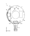
- FIG. 1 is a cross-sectional view schematically showing a structure of a motor 1 according to Embodiment 1 of the present invention.
- FIG. 2 is a front view schematically showing the structure of the motor 1.
- FIG. 3 is a front view schematically showing the structure of the stator assembly 3. However, the stator assembly 3 shown in FIG. 3 is in a state before molding of the resin 6.
- the electric motor 1 (also referred to as a molded electric motor) has a rotor 2 (also referred to as a rotor assembly), a stator assembly 3 (also referred to as a molded stator), a heat sink 5 as a heat dissipation member, and bearings 7a and 7b. .
- the motor 1 further includes a bracket 8 and a waterproof rubber 9 for sealing the motor 1.
- the motor 1 is, for example, a permanent magnet synchronous motor, but is not limited thereto.
- the bearings 7 a and 7 b rotatably support both ends of the shaft 22 of the rotor 2.
- the rotor 2 has a rotor core 21 and a shaft 22.
- the rotor 2 is rotatable about the rotation axis (ie, the axis A1).
- the rotor 2 is rotatably provided inside the stator assembly 3 (specifically, the stator 30) via an air gap.
- the rotor 2 may further have permanent magnets for forming the magnetic poles of the rotor 2.
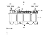
- the stator assembly 3 includes a stator 30, a printed circuit board 4, lead wires 41 connected to the printed circuit board 4, a drive circuit 42 fixed to the surface of the printed circuit board 4, and resin 6 (also referred to as mold resin). And.
- FIG. 4 is a front view schematically showing the structure of the stator 30.
- FIG. 5 is a side view schematically showing the structure of the stator 30. As shown in FIG.
- the stator 30 has a stator core 31 in which a plurality of electromagnetic steel plates are stacked in the axial direction, a winding 32 (also referred to as a stator winding), and an insulator 33 as an insulating portion.
- a winding 32 also referred to as a stator winding
- an insulator 33 as an insulating portion.
- Each of the plurality of magnetic steel sheets is formed into a predetermined shape by a punching process, and fixed to each other by caulking, welding, adhesion or the like.
- the winding 32 is, for example, a magnet wire.
- a coil is formed by winding the winding 32 around the insulator 33 combined with the stator core 31.
- the winding 32 is electrically connected to the terminal 32a (winding terminal).
- the end of the winding 32 is hooked on the hook of the terminal 32a and is fixed to the terminal 32a by fusing or solder.
- the terminal 32 a is fixed to the insulator 33 and is electrically connected to the printed circuit board 4.
- the insulator 33 has at least one fixing portion 331 for fixing the printed circuit board 4.
- the insulator 33 is, for example, a thermoplastic resin such as PBT (polybutylene terephthalate).
- the insulator 33 electrically insulates the stator core 31 (for example, the teeth of the stator core 31).
- the insulator 33 is, for example, integrally formed with the stator core 31. However, the insulator 33 may be formed in advance, and the formed insulator 33 may be combined with the stator core 31.
- the printed circuit board 4 has positioning holes 43 (also simply referred to as “holes”) that engage with the fixing portions 331 (specifically, the protrusions 331 a) of the insulator 33.
- the fixing portion 331 of the insulator 33 has a protrusion 331 a and a support portion 331 b.
- the protrusions 331a are inserted into positioning holes 43 formed in the printed circuit board 4 (FIG. 3). Thereby, the printed circuit board 4 is fixed to the insulator 33.
- the support portion 331 b axially supports the printed circuit board 4 and positions the printed circuit board 4 in the axial direction.
- the printed circuit board 4 is integrated with the stator 30 by the resin 6 (FIG. 1).
- the drive circuit 42 controls the rotation of the rotor 2.
- the drive circuit 42 includes, for example, a drive element 42 a and a Hall IC (Integrated Circuit) 42 b.
- the drive element 42a is, for example, a power transistor.
- the drive element 42a is electrically connected to the winding 32, and supplies the winding 32 with a drive current based on the current supplied from the outside or the inside (for example, a battery) of the motor 1.
- the drive element 42 a controls the rotation of the rotor 2.
- the Hall IC 42 b detects the rotational position of the rotor 2 by detecting the magnetic field from the rotor 2.
- the resin 6 is, for example, a thermosetting resin such as BMC (bulk molding compound).
- BMC is suitable for insert molding to enable low pressure molding. Thereby, when shaping
- the resin 6 may be a thermoplastic resin such as PPS (polyphenylene sulfide). Since heat conductivity of PPS is improved compared to BMC, the heat of the stator assembly 3 is easily transmitted to the heat sink 5. Thereby, the heat dissipation of the electric motor 1 can be improved, and the temperature rise of the printed circuit board 4 and the winding 32 can be suppressed.
- PPS polyphenylene sulfide
- the heat sink 5 is formed of, for example, a metal material such as aluminum.
- the outer shape of the heat sink 5 (specifically, the planar shape on the xy plane) is circular.
- the heat sink 5 is integrated with the stator assembly 3 by the resin 6 by fitting a part of the heat sink 5 (a base 51 described later) with the resin 6.
- the heat sink 5 is fixed to the stator assembly 3 and dissipates the heat of the stator assembly 3 (for example, the heat generated from the stator 30 or the drive circuit 42) to the outside of the motor 1.
- a part of the heat sink 5 for example, the heat radiating portion 52 shown in FIG. 2 is exposed to the outside of the motor 1 (specifically, the resin 6). Thereby, the heat generated from the stator assembly 3 is released to the outside of the motor 1.
- the heat sink 5 may be in contact with the printed circuit board 4. When the heat sink 5 is in contact with the printed circuit board 4, the heat of the printed circuit board 4 can be efficiently dissipated to the outside of the motor 1.
- a heat dissipation assisting member formed of a material having high thermal conductivity may be disposed between the printed circuit board 4 and the heat sink 5. Thereby, the heat of the stator assembly 3 can be efficiently released to the outside of the motor 1.
- the heat radiation assisting member can be formed, for example, in a sheet shape or a block shape.
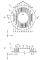
- FIG. 6 (a) is a plan view schematically showing an example of the heat sink 5
- FIG. 6 (b) is a cross-sectional view taken along the line 6b-6b shown in FIG. 6 (a).
- the heat sink 5 has a base portion 51 and a heat radiating portion 52 integrally formed with the base portion 51.
- the base portion 51 is an outer edge of the heat sink 5 and has a width in the radial direction of the heat sink 5 (also referred to as “radial direction of the rotor 2” or simply “radial direction”).
- the outer shape of the base 51 (specifically, the planar shape on the xy plane) is circular.
- the heat radiating portion 52 is formed inside the base portion 51 in the radial direction.
- the heat radiating portion 52 has a plurality of fins 53. Each fin 53 protrudes in the axial direction.
- the heat radiating portion 52 has at least one heat radiating surface 53a.
- the heat dissipation surface 53 a is an upper surface of each fin 53.
- FIG. 7 is a flowchart showing an example of a manufacturing process of the motor 1.
- the method of manufacturing the motor 1 includes the steps described below.
- step S1 the stator 30 is manufactured.
- stator iron core 31 is formed by laminating a plurality of electromagnetic steel plates in the axial direction.
- the insulator 33 formed in advance is attached to the stator core 31, and the winding 32 is wound around the stator core 31 and the insulator 33. Thereby, the stator 30 is obtained.
- the protrusion 331 a of the insulator 33 is inserted into the positioning hole 43 of the printed circuit board 4.
- a drive circuit 42 is fixed in advance to the surface of the printed circuit board 4.
- the lead wires 41 are also attached to the printed circuit board 4 in advance.
- the protrusion 331 a protruding from the positioning hole 43 may be fixed to the printed circuit board 4 by heat welding or ultrasonic welding or the like.
- FIG. 8 is a cross-sectional view showing the stator 30 and the heat sink 5 disposed in the mold 100.
- the stator 30 and the heat sink 5 are disposed in the mold 100.
- the stator 30 is disposed in the first mold 101 on the fixed side of the mold 100, and the heat sink 5 fabricated in advance is combined with the stator 30.
- the second mold 102 is combined with the first mold 101 such that the inner surface 102 a of the movable second mold 102 of the mold 100 contacts the base portion 51 of the heat sink 5.
- the second mold 102 is combined with the first mold 101 so that no gap is generated between the inner surface 102 a of the second mold 102 and the base 51.
- step S3 the resin 6 is molded. Specifically, the resin 6 is injected into the mold 100. Thus, the base portion 51 is fitted with the resin 6, and the heat sink 5 is integrated with the stator 30 and the printed circuit board 4 by the resin 6. Thereby, the stator assembly 3 is obtained.
- step S4 the rotor 2 is manufactured.
- the shaft 22 is inserted into an axial hole formed in the rotor core 21 to obtain the rotor 2.
- Permanent magnets forming the magnetic poles may be attached to the rotor core 21 in advance.
- step S5 the shaft 22 is inserted into the bearings 7a and 7b.
- step S1 to step S5 is not limited to the order shown in FIG.
- the steps from step S1 to step S3 and step S4 can be performed in parallel with each other.
- Step S4 may be performed prior to steps S1 to S3.
- step S6 the rotor 2 is inserted into the stator assembly 3 (specifically, the stator 30) together with the bearings 7a and 7b.
- step S7 the bracket 8 is fitted inside the resin 6, and the waterproof rubber 9 is fitted on the shaft 22.
- the motor 1 is assembled by the steps described above.
- FIG. 9 (a) is a plan view schematically showing another example of the heat sink 5 as the heat sink 5a
- FIG. 9 (b) is a cross section taken along line 9b-9b shown in FIG. 9 (a).
- the structure of the heat radiating portion 52 a is different from the structure of the heat radiating portion 52 of the heat sink 5.
- the other structure of the heat sink 5 a is the same as that of the heat sink 5.
- the heat sink 5 a is applicable to the motor 1 instead of the heat sink 5.
- the heat sink 5a has a base portion 51 and a heat radiating portion 52a.
- the heat radiating portion 52a has a plurality of fins 53, a heat radiating surface 54a (first heat radiating surface), a heat radiating surface 53a (second heat radiating surface), an outer circumferential surface 54b, and a hollow portion 54c.
- the hollow portion 54 c penetrates the base portion 51 and the heat radiating portion 52 in the axial direction.
- the hollow portion 54c extends in the circumferential direction and has a width in the axial direction. The axial length of the hollow portion 54c may be adjusted according to the position of the bearing 7b.
- the heat dissipation surface 54a is formed on the side opposite to the base portion 51 in the axial direction, and the circumferential direction of the heat sink 5 (hereinafter simply referred to as “circumferential direction”) about the rotation axis (that is, the axis A1) of the rotor 2 To extend).
- the heat dissipation surface 54a has a width in the radial direction.
- the heat sink 5 is fixed to the stator assembly 3, the heat radiation efficiency of the motor 1 can be enhanced.
- the inner surface 102a of the second mold 102 on the movable side of the mold 100 is in the manufacturing process of the motor 1 (specifically, step S2 in FIG. 7).
- the second mold 102 can be combined with the first mold 101 to contact the base 51 of the heat sink 5.
- the resin 6 passes through between the inner surface 102a of the second mold 102 and the base portion 51. It can prevent.
- the resin 6 can be prevented from entering the heat radiating portion 52 (for example, the fins 53).
- the heat dissipation efficiency of the motor 1 can be enhanced.
- the heat sink 5 can be integrated with the stator assembly 3 such that the bearing 7b is located inside the hollow portion 54c.
- the distance from the stator assembly 3 (for example, the printed circuit board 4 and the drive circuit 42) to the heat sink 5 is shortened, so the heat dissipation efficiency of the motor 1 can be enhanced.
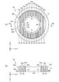
- FIG. 10 (a) is a plan view schematically showing the structure of the heat sink 5b
- FIG. 10 (b) is a cross-sectional view taken along line 10b-10b shown in FIG. 10 (a).
- the structure of the heat sink 5 b is different from the structure of the heat sink 5 in the motor 1 according to the first embodiment.
- the structure other than the heat sink 5 b is the same as the structure of the motor 1 according to the first embodiment.
- the heat sink 5 b has a base portion 51 and a heat radiating portion 52 b integrally formed with the base portion 51.
- the heat radiating portion 52 b includes a plurality of fins 53, a heat radiating surface 54 a (first heat radiating surface), a heat radiating surface 53 a (second heat radiating surface), and an outer circumferential surface 54 b as a heat radiating wall (first wall).
- a hollow portion 54c and a heat radiation wall 54d (second wall) are provided. The hollow portion 54c penetrates the base portion 51 and the heat radiating portion 52b in the axial direction.
- the heat dissipation surface 54a is formed on the opposite side to the base 51 in the axial direction, and extends in the circumferential direction.
- the heat sink 5b further has at least one recess 55 for positioning the heat sink 5b.
- the recess 55 is formed in the heat radiation surface 54a.
- the position of the recess 55 may be other than the heat dissipation surface 54a.
- the recess 55 is, for example, a notch or a hole.
- the heat dissipation surface 53 a is an upper surface of each fin 53.
- the heat radiation surface 53a is formed on the outer side in the axial direction and the radial direction than the heat radiation surface 54a.
- the outer circumferential surface 54b forms an outer surface of the heat radiating portion 52b in the circumferential direction, and is axially long.
- the heat dissipation wall 54d is formed between the heat dissipation surface 54a and the heat dissipation surface 53a.
- the heat dissipation wall 54 d extends in the circumferential direction and has a width in the axial direction.
- FIG. 11 is a cross-sectional view showing the stator 30 and the heat sink 5 b disposed in the mold 100.
- the process in step S2 shown in FIG. 7 is different from the method of manufacturing the motor 1 according to the first embodiment.
- the stator 30 is disposed in the first mold 101 on the fixed side of the mold 100, and the heat sink 5b manufactured in advance is combined with the stator 30.
- the second mold 102 is formed so that the inner surface 102a of the second mold 102 on the movable side of the mold 100 contacts the base 51, the outer peripheral surface 54b, the heat dissipation surface 54a, and the heat dissipation wall 54d. Combine with the type 101 of.
- the second mold 102 is used as a first mold so that no gap is generated between the inner surface 102a of the second mold 102, the base portion 51, the outer peripheral surface 54b, the heat dissipation surface 54a, and the heat dissipation wall 54d. Combine with 101.
- step S2 In the method of manufacturing a motor according to the second embodiment, the processes other than step S2 are the same as the method of manufacturing the motor 1 according to the first embodiment.
- the motor according to the second embodiment has the same effect as the effect of the motor 1 according to the first embodiment (including the effect of the modification).
- the method of manufacturing the motor according to the second embodiment has the same effect as the method of manufacturing the motor 1 according to the first embodiment.
- the inner surface 102a of the second mold 102 on the movable side of the mold 100 is the base portion 51.
- the second mold 102 can be combined with the first mold 101 to be in contact with the outer peripheral surface 54b, the heat dissipation surface 54a, and the heat dissipation wall 54d.
- the resin 6 is injected into the mold 100 (specifically, step S3 in FIG. 7)
- the resin 6 passes through between the inner surface 102a of the second mold 102 and the base portion 51. It can prevent.
- the thermal radiation part 52b for example, fin 53
- the resin 6 flowing into the hollow portion 54c can be prevented from passing between the inner surface 102a and the heat dissipation surface 54a. Even when the resin 6 passes between the inner surface 102a and the heat radiation surface 54a, the heat radiation portion 52b (for example, the fins 53) is covered with the resin 6 because the inner surface 102a is in contact with the heat radiation wall 54d. It can prevent.
- the heat radiating portion 52b specifically, the plurality of fins 53 is exposed to the outside of the motor according to the second embodiment, so that the heat radiation efficiency of the motor can be enhanced.
- FIG. 12 (a) is a plan view schematically showing the structure of the heat sink 5c
- FIG. 12 (b) is a cross-sectional view taken along line 12b-12b shown in FIG. 12 (a).
- the structure of the heat sink 5c is different from the structure of the heat sink 5 in the motor 1 according to the first embodiment.
- the structure other than the heat sink 5c is the same as the structure of the motor 1 according to the first embodiment.
- the structure of the base 51a of the heat sink 5c is different from that of the base 51 of the heat sink 5b.
- the heat sink 5c has a base portion 51a and a heat dissipation portion 52b integrally formed with the base portion 51a.
- the base 51 a has at least one protrusion 56 and a flange 57.
- the protrusion 56 has a base surface 56 a (first base surface) which is an upper surface of the protrusion 56.
- the projecting portion 56 protrudes outward in the radial direction from the flange portion 57. Therefore, the base surface 56a protrudes outward in the radial direction.
- four protrusions 56 are formed on the heat sink 5c.
- the flange portion 57 has a base surface 57a (second base surface) and a step 57b (also referred to as a base wall) long in the axial direction.
- the base surface 57a is formed on the outer side ( ⁇ z side) in the axial direction than the base surface 56a, and is formed on the inner side in the radial direction than the base surface 56a. That is, the base surface 57a is a surface located between the base surface 56a and the heat dissipation surface 53a.
- the base surface 57a extends in the circumferential direction and protrudes in the radial direction. That is, the base surface 57a has a width in the radial direction.
- the step 57 b is formed between the base surface 56 a and the base surface 57 a.
- the step 57 b extends in the circumferential direction.
- the step 57 b has a width in the axial direction.
- FIG. 13 is a cross-sectional view showing the stator 30 and the heat sink 5c disposed in the mold 100. As shown in FIG. In the method of manufacturing the motor according to the third embodiment, the processes in steps S2 and S3 shown in FIG. 7 are different from the method of manufacturing the motor 1 according to the first embodiment.
- step S2 the stator 30 is disposed in the first mold 101 on the fixed side of the mold 100, and the heat sink 5c manufactured in advance is combined with the stator 30.
- the second mold 102 is formed so that the inner surface 102a of the movable second mold 102 on the movable side contacts the base surface 57a, the outer peripheral surface 54b, the heat dissipation surface 54a, and the heat dissipation wall 54d. Combine with the type 101 of.
- the second mold 102 is used as a first mold so that no gap is generated between the inner surface 102a of the second mold 102, the base surface 57a, the outer peripheral surface 54b, the heat dissipation surface 54a, and the heat dissipation wall 54d. Combine with 101. A gap is provided between the inner surface 102a and a part of the base 51a (specifically, the base surface 56a).
- step S3 the resin 6 is molded. Specifically, the resin 6 is injected into the mold 100. More specifically, the resin 6 is injected into the mold 100 so that the resin 6 enters between the inner surface 102 a and a part of the base 51 a (specifically, the base surface 56 a of the projection 56). Do. Furthermore, the resin 6 is injected into the mold 100 so that the protrusion 56 is covered with the resin 6. Thereby, a part of the base portion 51a (specifically, the base surface 56a of the projecting portion 56) is engaged with the resin 6, and the heat sink 5 is integrated with the stator 30 and the printed circuit board 4 by the resin 6. . Furthermore, the protrusion 56 is covered with the resin 6. Thereby, the stator assembly 3 is obtained.
- the manufacturing method of the motor according to the third embodiment is the same as the manufacturing method of the motor 1 according to the first embodiment except for steps S2 and S3.
- the motor according to the third embodiment has the same effects as the effects of the motor 1 according to the first embodiment (including the effects of the modification) and the motor according to the second embodiment.
- the method of manufacturing the motor according to the third embodiment has the same effect as the method of manufacturing the motor 1 according to the first embodiment and the method of manufacturing the motor according to the second embodiment.
- the heat sink 5 c can be prevented from rotating with respect to the resin 6. In other words, the displacement of the heat sink 5 c in the circumferential direction with respect to the resin 6 can be prevented.
- the resin 6 is filled between the inner surface 102a of the mold 100 and the projection 56 (specifically, the base surface 56a). Deviation of the heat sink 5c in the direction can be prevented.
- the heat sink 5c can be integrated with the stator assembly 3 without using fixing parts such as screws. Therefore, the number of parts of the motor according to the third embodiment and the number of manufacturing steps of the motor can be reduced, and the cost of the motor can be reduced.
- the projecting portion 56 in the base portion 51a, a part of the base portion 51a is made of resin 6 without forming a groove in the mold 100 (specifically, the second mold 102). It can be covered. Therefore, the manufacturing cost of the mold 100 can be reduced. Furthermore, since the projection 56 is formed on the base 51a, the portion covered with the resin 6 can be obtained, and the ratio of the surface area of the heat radiating portion 52b in the heat sink 5c can be increased. Thereby, the heat dissipation efficiency in the motor can be enhanced.
- FIG. 14 is a diagram schematically showing a configuration of the air conditioner 10 according to Embodiment 4 of the present invention.
- An air conditioner 10 for example, a refrigeration air conditioner
- An air conditioner 10 includes an indoor unit 11 as a fan (first fan), a refrigerant pipe 12, and a fan connected to the indoor unit 11 by a refrigerant pipe 12. And an outdoor unit 13 as a (second blower).
- the indoor unit 11 has a motor 11a (for example, the motor 1 according to the first embodiment), a blower 11b for blowing air by being driven by the motor 11a, and a housing 11c covering the motor 11a and the blower 11b.
- the blower 11b has, for example, a blade driven by the motor 11a.
- the outdoor unit 13 has a motor 13a (for example, the motor 1 according to the first embodiment), a blower 13b, a compressor 14, and a heat exchanger (not shown).
- the blower 13 b blows by being driven by the motor 13 a.
- the blower 13 b has, for example, a blade driven by the motor 13 a.
- the compressor 14 includes an electric motor 14a (for example, the electric motor 1 according to the first embodiment), a compression mechanism 14b (for example, a refrigerant circuit) driven by the electric motor 14a, and a housing 14c covering the electric motor 14a and the compression mechanism 14b.
- an electric motor 14a for example, the electric motor 1 according to the first embodiment
- a compression mechanism 14b for example, a refrigerant circuit driven by the electric motor 14a
- a housing 14c covering the electric motor 14a and the compression mechanism 14b.
- At least one of the indoor unit 11 and the outdoor unit 13 has the motor (including the modification) described in the first to third embodiments.
- the electric motors described in the first to third embodiments are applied to at least one of the electric motors 11a and 13a as a drive source of the blower unit.
- the motor 14a of the compressor 14 the motor (including the modification) described in the first to third embodiments may be used.
- the air conditioner 10 can perform, for example, an operation such as a cooling operation in which cold air is blown from the indoor unit 11 or a heating operation in which warm air is blown.
- the motor 11a is a drive source for driving the blower 11b.
- the blower 11b can blow the adjusted air.
- the motor (including the modification) described in the first to third embodiments is applied to at least one of the motors 11a and 13a.
- the same effect as the effect described in 3 can be obtained.
- failure of the air conditioner 10 resulting from heat generation of the motor can be prevented.
- the cost of the air conditioner 10 can be reduced by using the electric motor described in the first to third embodiments in the air conditioner 10.
- the motor according to the first to third embodiments (including the modification) as a drive source of the fan (for example, the indoor unit 11), the same effect as the first to third embodiments can be obtained. be able to. Thereby, the failure of the blower caused by the heat generation of the motor can be prevented.
- the motor described in the first to third embodiments can be mounted on an apparatus having a drive source, such as a ventilation fan, a home appliance, or a machine tool, in addition to the air conditioner 10.
- a drive source such as a ventilation fan, a home appliance, or a machine tool, in addition to the air conditioner 10.
Abstract
電動機(1)は、固定子組立(3)と、固定子組立(3)の内側に備えられた回転子(2)と、前記固定子組立(3)の熱を放出するヒートシンク(5)とを有する。ヒートシンク(5)は、ベース部(51)と、ベース部(51)と一体的に形成された放熱部(52)とを有する。
Description
本発明は、ヒートシンクを有する電動機に関する。
一般に、電動機の熱を外部に放出するため、放熱部材としてのヒートシンクが用いられている。例えば、U字型のヒートシンクを備えた電動機が提案されている(例えば、特許文献1参照)。
しかしながら、特許文献1で開示されているヒートシンクはU字型であるため、加工が複雑化するという問題がある。さらに、特許文献1で開示されているヒートシンクは、樹脂で覆われており、放熱効率が低下するという問題がある。
本発明の目的は、電動機における放熱効率を高めることである。
本発明の電動機は、固定子組立と、前記固定子組立の内側に備えられた回転子と、前記固定子組立に固定されており、前記固定子組立の熱を放出するヒートシンクとを備え、前記ヒートシンクは、ベース部と、前記ベース部と一体的に形成された放熱部とを有する。
本発明によれば、電動機における放熱効率を高めることができる。
実施の形態1.
本発明の実施の形態1に係る電動機1について以下に説明する。
各図に示されるxyz直交座標系において、z軸方向(z軸)は、電動機1のシャフト22の軸線A1(すなわち、回転子2の回転軸)と平行な方向(「回転子2の軸方向」又は単に「軸方向」ともいう)を示し、x軸方向(x軸)は、z軸方向(z軸)に直交する方向を示し、y軸方向は、z軸方向及びx軸方向の両方に直交する方向を示す。
本発明の実施の形態1に係る電動機1について以下に説明する。
各図に示されるxyz直交座標系において、z軸方向(z軸)は、電動機1のシャフト22の軸線A1(すなわち、回転子2の回転軸)と平行な方向(「回転子2の軸方向」又は単に「軸方向」ともいう)を示し、x軸方向(x軸)は、z軸方向(z軸)に直交する方向を示し、y軸方向は、z軸方向及びx軸方向の両方に直交する方向を示す。
図1は、本発明の実施の形態1に係る電動機1の構造を概略的に示す断面図である。
図2は、電動機1の構造を概略的に示す正面図である。
図3は、固定子組立3の構造を概略的に示す正面図である。ただし、図3に示される固定子組立3は、樹脂6の成形前の状態である。
図2は、電動機1の構造を概略的に示す正面図である。
図3は、固定子組立3の構造を概略的に示す正面図である。ただし、図3に示される固定子組立3は、樹脂6の成形前の状態である。
電動機1(モールド電動機ともいう)は、回転子2(回転子組立ともいう)と、固定子組立3(モールド固定子ともいう)と、放熱部材としてのヒートシンク5と、ベアリング7a及び7bとを有する。図1に示される例では、電動機1は、さらに、ブラケット8と、電動機1を密閉する防水ゴム9とを有する。電動機1は、例えば、永久磁石同期電動機であるが、これに限定されない。ベアリング7a及び7bは、回転子2のシャフト22の両端を回転自在に支持する。
回転子2は、回転子鉄心21と、シャフト22とを有する。回転子2は、回転軸(すなわち、軸線A1)を中心として回転自在である。回転子2は、固定子組立3(具体的には、固定子30)の内側に、空隙を介して回転自在に備えられている。回転子2は、さらに、回転子2の磁極を形成するための永久磁石を有してもよい。
固定子組立3は、固定子30と、プリント基板4と、プリント基板4に接続されたリード線41と、プリント基板4の表面に固定された駆動回路42と、樹脂6(モールド樹脂ともいう)とを有する。
図4は、固定子30の構造を概略的に示す正面図である。
図5は、固定子30の構造を概略的に示す側面図である。
図5は、固定子30の構造を概略的に示す側面図である。
固定子30は、複数の電磁鋼板が軸方向に積層された固定子鉄心31と、巻線32(固定子巻線ともいう)と、絶縁部としてのインシュレータ33とを有する。複数の電磁鋼板の各々は、打ち抜き処理によって、予め定められた形状に形成され、かしめ、溶接、又は接着等によって互いに固定される。
巻線32は、例えば、マグネットワイヤである。巻線32が、固定子鉄心31と組み合わされたインシュレータ33に巻回されることによりコイルが形成される。巻線32は、端子32a(巻線端子)と電気的に接続されている。図5に示される例では、巻線32の端部は、端子32aのフック部に引っ掛けられており、ヒュージング又は半田などによって端子32aに固定されている。端子32aは、インシュレータ33に固定されており、プリント基板4と電気的に接続されている。
インシュレータ33は、プリント基板4を固定する少なくとも1つの固定部331を有する。インシュレータ33は、例えば、PBT(ポリブチレンテレフタレート)等の熱可塑性樹脂である。インシュレータ33は、固定子鉄心31(例えば、固定子鉄心31のティース部)を電気的に絶縁する。インシュレータ33は、例えば、固定子鉄心31と一体に成形される。ただし、予めインシュレータ33を成形し、成形されたインシュレータ33を固定子鉄心31と組み合わせてもよい。
プリント基板4は、インシュレータ33の固定部331(具体的には、突起331a)と係合する位置決め穴43(単に「穴」ともいう)を有する。
インシュレータ33の固定部331は、突起331aと支持部331bとを有する。突起331aは、プリント基板4に形成された位置決め穴43に挿入されている(図3)。これにより、プリント基板4がインシュレータ33に固定される。支持部331bは、プリント基板4を軸方向に支持し、軸方向においてプリント基板4を位置決めする。
プリント基板4は、樹脂6によって固定子30と一体化されている(図1)。駆動回路42は、回転子2の回転を制御する。駆動回路42は、例えば、駆動素子42a及びホールIC(Integrated Circuit)42bを含む。
駆動素子42aは、例えば、パワートランジスタである。駆動素子42aは、電気的に巻線32と接続されており、電動機1の外部又は内部(例えば、バッテリ)から供給された電流に基づく駆動電流を巻線32に供給する。これにより、駆動素子42aは、回転子2の回転を制御する。
例えば、ホールIC42bは、回転子2からの磁界を検出することにより、回転子2の回転位置を検出する。
樹脂6は、例えば、BMC(バルクモールディングコンパウンド)などの熱硬化性樹脂である。BMCは、低圧成形を可能にするため、インサート成形に適している。これにより、金型を用いて樹脂6の成形を行うときに、プリント基板4又は固定子30などのインサート物の変形を防止することができ、電動機1の品質を向上させることができる。
樹脂6は、PPS(ポリフェニレンスルファイド)などの熱可塑性樹脂でもよい。PPSは、BMCに比べて熱伝導率が向上するので、固定子組立3の熱がヒートシンク5に伝わりやすい。これにより、電動機1の放熱性が向上し、プリント基板4及び巻線32の温度上昇を抑えることができる。
ヒートシンク5は、例えば、アルミニウムなどの金属材料によって形成される。図2に示される例では、ヒートシンク5の外形(具体的には、xy平面上における平面形状)は円形である。ヒートシンク5の一部(後述するベース部51)が樹脂6と嵌合することにより、ヒートシンク5が樹脂6によって固定子組立3と一体化されている。
ヒートシンク5は、固定子組立3に固定されており、固定子組立3の熱(例えば、固定子30又は駆動回路42から生じる熱)を電動機1の外部に放出する。ヒートシンク5の一部(例えば、図2に示される放熱部52)は、電動機1(具体的には、樹脂6)の外部に露出している。これにより、固定子組立3から生じる熱が電動機1の外部に放出される。
ヒートシンク5は、プリント基板4に接触していてもよい。ヒートシンク5がプリント基板4に接触している場合、プリント基板4の熱を効率的に電動機1の外部に放出させることができる。
プリント基板4とヒートシンク5との間に、高い熱伝導率を持つ材料で形成された放熱補助部材を配置してもよい。これにより、固定子組立3の熱を効率的に電動機1の外部に放出させることができる。放熱補助部材は、例えば、シート状又はブロック状に形成することができる。
図6(a)は、ヒートシンク5の一例を概略的に示す平面図であり、図6(b)は、図6(a)に示される線6b-6bに沿った断面図である。
ヒートシンク5は、ベース部51と、ベース部51と一体的に形成された放熱部52とを有する。
ヒートシンク5は、ベース部51と、ベース部51と一体的に形成された放熱部52とを有する。
ベース部51は、ヒートシンク5の外縁であり、ヒートシンク5の径方向(「回転子2の径方向」又は、単に「径方向」ともいう)における幅を持つ。図6(a)に示される例では、ベース部51の外形(具体的には、xy平面上における平面形状)は円形である。放熱部52は、径方向におけるベース部51の内側に形成されている。放熱部52は、複数のフィン53を有する。各フィン53は、軸方向に突出している。放熱部52は、少なくとも1つの放熱面53aを有する。放熱面53aは、各フィン53の上面である。
電動機1の製造方法の一例について以下に説明する。
図7は、電動機1の製造工程の一例を示すフローチャートである。電動機1の製造方法は、以下に説明されるステップを含む。
図7は、電動機1の製造工程の一例を示すフローチャートである。電動機1の製造方法は、以下に説明されるステップを含む。
ステップS1では、固定子30を作製する。例えば、複数の電磁鋼板を軸方向に積層することにより、固定子鉄心31を形成する。さらに、固定子鉄心31に、予め形成されたインシュレータ33を取り付け、固定子鉄心31及びインシュレータ33に巻線32を巻き付ける。これにより、固定子30が得られる。さらに、プリント基板4の位置決め穴43に、インシュレータ33の突起331aを挿入する。プリント基板4の表面には、駆動回路42が予め固定されている。リード線41も、プリント基板4に予め取り付けておくことが望ましい。熱溶着又は超音波溶着などによって、位置決め穴43から突出した突起331aを、プリント基板4に固定してもよい。
図8は、金型100内に配置された固定子30及びヒートシンク5を示す断面図である。
ステップS2では、固定子30及びヒートシンク5を金型100内に配置する。具体的には、金型100の固定側の第1の型101内に固定子30を配置し、予め作製されたヒートシンク5を固定子30と組み合わせる。さらに、金型100の可動側の第2の型102の内側表面102aがヒートシンク5のベース部51に接触するように、第2の型102を第1の型101と組み合わせる。この場合、第2の型102の内側表面102aとベース部51との間に隙間が生じないように第2の型102を第1の型101と組み合わせる。
ステップS2では、固定子30及びヒートシンク5を金型100内に配置する。具体的には、金型100の固定側の第1の型101内に固定子30を配置し、予め作製されたヒートシンク5を固定子30と組み合わせる。さらに、金型100の可動側の第2の型102の内側表面102aがヒートシンク5のベース部51に接触するように、第2の型102を第1の型101と組み合わせる。この場合、第2の型102の内側表面102aとベース部51との間に隙間が生じないように第2の型102を第1の型101と組み合わせる。
ステップS3では、樹脂6を成形する。具体的には、樹脂6を金型100内に注入する。これにより、ベース部51が樹脂6と嵌合し、ヒートシンク5が、樹脂6によって固定子30及びプリント基板4と一体化される。これにより、固定子組立3が得られる。
ステップS4では、回転子2を作製する。例えば、回転子鉄心21に形成された軸穴にシャフト22を挿入し、回転子2を得る。磁極を形成する永久磁石を、予め回転子鉄心21に取り付けておいてもよい。
ステップS5では、シャフト22をベアリング7a及び7bに挿入する。
ステップS1からステップS5までの順序は、図7に示される順序に限られない。例えば、ステップS1からステップS3までのステップと、ステップS4とは、互いに並行して行うことができる。ステップS4は、ステップS1からステップS3までのステップよりも先に行われてもよい。
ステップS6では、固定子組立3(具体的には、固定子30)の内側に、回転子2をベアリング7a及び7bと共に挿入する。
ステップS7では、樹脂6の内側にブラケット8を嵌め、シャフト22に防水ゴム9を嵌める。
以上に説明した工程により電動機1が組み立てられる。
変形例.
図9(a)は、ヒートシンク5の他の例を、ヒートシンク5aとして概略的に示す平面図であり、図9(b)は、図9(a)に示される線9b-9bに沿った断面図である。
図9(a)は、ヒートシンク5の他の例を、ヒートシンク5aとして概略的に示す平面図であり、図9(b)は、図9(a)に示される線9b-9bに沿った断面図である。
ヒートシンク5aにおいて、放熱部52aの構造がヒートシンク5の放熱部52の構造と異なる。ヒートシンク5aのその他の構造は、ヒートシンク5と同じである。ヒートシンク5aは、ヒートシンク5の代わりに電動機1に適用可能である。
具体的には、ヒートシンク5aは、ベース部51と、放熱部52aとを有する。放熱部52aは、複数のフィン53と、放熱面54a(第1の放熱面)と、放熱面53a(第2の放熱面)と、外周面54bと、中空部54cとを有する。中空部54cは、軸方向にベース部51及び放熱部52を貫通している。中空部54cは、周方向に延在しており、軸方向における幅を持つ。中空部54cの軸方向における長さは、ベアリング7bの位置に応じて調整すればよい。
放熱面54aは、軸方向においてベース部51とは反対側に形成されており、且つ回転子2の回転軸(すなわち、軸線A1)を中心とするヒートシンク5の周方向(以下、単に「周方向」という)に延在する。放熱面54aは、径方向における幅を持つ。
実施の形態1に係る電動機1の効果(変形例の効果を含む)及び電動機1の製造方法の効果を以下に説明する。
実施の形態1に係る電動機1によれば、固定子組立3にヒートシンク5が固定されているので、電動機1の放熱効率を高めることができる。
さらに、実施の形態1に係る電動機1によれば、電動機1の製造工程(具体的には、図7におけるステップS2)において、金型100の可動側の第2の型102の内側表面102aがヒートシンク5のベース部51に接触するように、第2の型102を第1の型101と組み合わせることができる。これにより、樹脂6を金型100内に注入するとき(具体的には、図7におけるステップS3)、第2の型102の内側表面102aとベース部51との間を樹脂6が通り抜けることを防ぐことができる。その結果、樹脂6が放熱部52(例えば、フィン53)へ入り込むことを防ぐことができる。
したがって、放熱部52の一部、具体的には、複数のフィン53が電動機1の外部に露出されるので、電動機1における放熱効率を高めることができる。
変形例では、放熱部52aは中空部54cを有するので、ベアリング7bが中空部54cの内側に位置するようにヒートシンク5を固定子組立3と一体化させることができる。これにより、固定子組立3(例えば、プリント基板4及び駆動回路42)からヒートシンク5までの距離が短くなるので、電動機1における放熱効率を高めることができる。
実施の形態2.
実施の形態2に係る電動機に用いられるヒートシンク5bについて説明する。
図10(a)は、ヒートシンク5bの構造を概略的に示す平面図であり、図10(b)は、図10(a)に示される線10b-10bに沿った断面図である。
実施の形態2に係る電動機では、ヒートシンク5bの構造が実施の形態1に係る電動機1におけるヒートシンク5の構造と異なる。実施の形態2に係る電動機において、ヒートシンク5b以外の構造は、実施の形態1に係る電動機1の構造と同じである。
実施の形態2に係る電動機に用いられるヒートシンク5bについて説明する。
図10(a)は、ヒートシンク5bの構造を概略的に示す平面図であり、図10(b)は、図10(a)に示される線10b-10bに沿った断面図である。
実施の形態2に係る電動機では、ヒートシンク5bの構造が実施の形態1に係る電動機1におけるヒートシンク5の構造と異なる。実施の形態2に係る電動機において、ヒートシンク5b以外の構造は、実施の形態1に係る電動機1の構造と同じである。
ヒートシンク5bは、ベース部51と、ベース部51と一体的に形成された放熱部52bとを有する。放熱部52bは、複数のフィン53と、放熱面54a(第1の放熱面)と、放熱面53a(第2の放熱面)と、放熱壁(第1の壁)としての外周面54bと、中空部54cと、放熱壁54d(第2の壁)とを有する。中空部54cは、軸方向にベース部51及び放熱部52bを貫通している。
放熱面54aは、軸方向においてベース部51とは反対側に形成されており、且つ周方向に延在する。ヒートシンク5bは、さらにヒートシンク5bの位置決め用の少なくとも1つの窪み55を有する。本実施の形態では、窪み55は、放熱面54aに形成されている。ただし、窪み55の位置は放熱面54a以外でもよい。窪み55は、例えば、切り欠き又は穴である。電動機1の製造工程において、固定子組立3に備えられた突起を窪み55に挿入することにより、固定子組立3に対するヒートシンク5bの位置決めを容易に行うことができる。
放熱面53aは、各フィン53の上面である。放熱面53aは、放熱面54aよりも軸方向及び径方向における外側に形成されている。
外周面54bは、周方向における放熱部52bの外側表面を形成し、且つ軸方向に長い。
放熱壁54dは、放熱面54aと放熱面53aとの間に形成されている。放熱壁54dは、周方向に延在しており、軸方向における幅を持つ。
実施の形態2に係る電動機の製造方法の一例について以下に説明する。
図11は、金型100内に配置された固定子30及びヒートシンク5bを示す断面図である。
実施の形態2に係る電動機の製造方法では、図7に示されるステップS2における処理が、実施の形態1に係る電動機1の製造方法と異なる。
図11は、金型100内に配置された固定子30及びヒートシンク5bを示す断面図である。
実施の形態2に係る電動機の製造方法では、図7に示されるステップS2における処理が、実施の形態1に係る電動機1の製造方法と異なる。
具体的には、金型100の固定側の第1の型101内に固定子30を配置し、予め作製されたヒートシンク5bを固定子30と組み合わせる。さらに、金型100の可動側の第2の型102の内側表面102aが、ベース部51、外周面54b、放熱面54a、及び放熱壁54dに接触するように、第2の型102を第1の型101と組み合わせる。この場合、第2の型102の内側表面102aと、ベース部51、外周面54b、放熱面54a、及び放熱壁54dとの間に隙間が生じないように第2の型102を第1の型101と組み合わせる。
実施の形態2に係る電動機の製造方法において、ステップS2以外の処理は、実施の形態1に係る電動機1の製造方法と同じである。
実施の形態2に係る電動機は、実施の形態1に係る電動機1の効果(変形例の効果を含む)と同じ効果を有する。
実施の形態2に係る電動機の製造方法は、実施の形態1に係る電動機1の製造方法と同じ効果を有する。
さらに、実施の形態2に係る電動機によれば、製造工程(具体的には、図7におけるステップS2)において、金型100の可動側の第2の型102の内側表面102aが、ベース部51、外周面54b、放熱面54a、及び放熱壁54dに接触するように、第2の型102を第1の型101と組み合わせることができる。これにより、樹脂6を金型100内に注入するとき(具体的には、図7におけるステップS3)、第2の型102の内側表面102aとベース部51との間を樹脂6が通り抜けることを防ぐことができる。その結果、放熱部52b(例えば、フィン53)が樹脂6で覆われることを防ぐことができる。
第2の型102の内側表面102aとベース部51との間を樹脂6が通り抜けた場合でも、内側表面102aが外周面54bと接触しているので、放熱部52b(例えば、フィン53)が樹脂6で覆われることを防ぐことができる。
さらに、内側表面102aが放熱面54aと接触しているので、中空部54cの内側に流入した樹脂6が、内側表面102aと放熱面54aとの間を通り抜けることを防ぐことができる。内側表面102aと放熱面54aとの間を樹脂6が通り抜けた場合でも、内側表面102aが放熱壁54dと接触しているので、放熱部52b(例えば、フィン53)が樹脂6で覆われることを防ぐことができる。
したがって、放熱部52bの一部、具体的には、複数のフィン53が実施の形態2に係る電動機の外部に露出されるので、この電動機における放熱効率を高めることができる。
実施の形態3.
実施の形態3に係る電動機に用いられるヒートシンク5cについて説明する。
図12(a)は、ヒートシンク5cの構造を概略的に示す平面図であり、図12(b)は、図12(a)に示される線12b-12bに沿った断面図である。
実施の形態3に係る電動機では、ヒートシンク5cの構造が実施の形態1に係る電動機1におけるヒートシンク5の構造と異なる。実施の形態3に係る電動機において、ヒートシンク5c以外の構造は、実施の形態1に係る電動機1の構造と同じである。実施の形態2に係る電動機と比較すると、実施の形態3に係る電動機において、ヒートシンク5cのベース部51aの構造が、ヒートシンク5bのベース部51と異なる。
実施の形態3に係る電動機に用いられるヒートシンク5cについて説明する。
図12(a)は、ヒートシンク5cの構造を概略的に示す平面図であり、図12(b)は、図12(a)に示される線12b-12bに沿った断面図である。
実施の形態3に係る電動機では、ヒートシンク5cの構造が実施の形態1に係る電動機1におけるヒートシンク5の構造と異なる。実施の形態3に係る電動機において、ヒートシンク5c以外の構造は、実施の形態1に係る電動機1の構造と同じである。実施の形態2に係る電動機と比較すると、実施の形態3に係る電動機において、ヒートシンク5cのベース部51aの構造が、ヒートシンク5bのベース部51と異なる。
ヒートシンク5cは、ベース部51aと、ベース部51aと一体的に形成された放熱部52bとを有する。
ベース部51aは、少なくとも1つの突出部56と、フランジ部57とを有する。
突出部56は、突出部56の上面であるベース面56a(第1のベース面)を有する。突出部56は、フランジ部57から径方向における外側に向けて突出している。したがって、ベース面56aは径方向における外側に向けて突出している。本実施の形態では、4つの突出部56がヒートシンク5cに形成されている。
フランジ部57は、ベース面57a(第2のベース面)と、軸方向に長い段差57b(ベース壁ともいう)とを有する。ベース面57aは、ベース面56aよりも軸方向における外側(-z側)に形成されており、且つベース面56aよりも径方向における内側に形成されている。すなわち、ベース面57aは、ベース面56aと放熱面53aとの間に位置する面である。ベース面57aは、周方向に延在しており、径方向に突出している。すなわち、ベース面57aは、径方向における幅を持つ。
段差57bは、ベース面56aとベース面57aとの間に形成されている。段差57bは、周方向に延在している。段差57bは、軸方向における幅を持つ。
実施の形態3に係る電動機の製造方法の一例について以下に説明する。
図13は、金型100内に配置された固定子30及びヒートシンク5cを示す断面図である。
実施の形態3に係る電動機の製造方法では、図7に示されるステップS2及びステップS3における処理が、実施の形態1に係る電動機1の製造方法と異なる。
図13は、金型100内に配置された固定子30及びヒートシンク5cを示す断面図である。
実施の形態3に係る電動機の製造方法では、図7に示されるステップS2及びステップS3における処理が、実施の形態1に係る電動機1の製造方法と異なる。
具体的には、ステップS2において、金型100の固定側の第1の型101内に固定子30を配置し、予め作製されたヒートシンク5cを固定子30と組み合わせる。さらに、金型100の可動側の第2の型102の内側表面102aが、ベース面57a、外周面54b、放熱面54a、及び放熱壁54dに接触するように、第2の型102を第1の型101と組み合わせる。この場合、第2の型102の内側表面102aと、ベース面57a、外周面54b、放熱面54a、及び放熱壁54dとの間に隙間が生じないように第2の型102を第1の型101と組み合わせる。内側表面102aとベース部51aの一部(具体的には、ベース面56a)との間には隙間を設ける。
ステップS3では、樹脂6を成形する。具体的には、樹脂6を金型100内に注入する。さらに具体的には、内側表面102aとベース部51aの一部(具体的には、突出部56のベース面56a)との間に樹脂6が入り込むように、樹脂6を金型100内に注入する。さらに、突出部56が樹脂6で覆われるように、樹脂6を金型100内に注入する。これにより、ベース部51aの一部(具体的には、突出部56のベース面56a)が樹脂6と嵌合し、ヒートシンク5が、樹脂6によって固定子30及びプリント基板4と一体化される。さらに、突出部56が樹脂6で覆われる。これにより、固定子組立3が得られる。
実施の形態3に係る電動機の製造方法において、ステップS2及びステップS3以外の処理は、実施の形態1に係る電動機1の製造方法と同じである。
実施の形態3に係る電動機は、実施の形態1に係る電動機1の効果(変形例の効果を含む)及び実施の形態2に係る電動機と同じ効果を有する。
実施の形態3に係る電動機の製造方法は、実施の形態1に係る電動機1の製造方法及び実施の形態2に係る電動機の製造方法と同じ効果を有する。
さらに、実施の形態3に係る電動機によれば、突出部56が樹脂6で覆われるので、ヒートシンク5cが樹脂6に対して回転することを防ぐことができる。言い換えると、樹脂6に対する周方向におけるヒートシンク5cのずれを防ぐことができる。
さらに、実施の形態3に係る電動機によれば、金型100の内側表面102aと突出部56(具体的には、ベース面56a)との間に樹脂6が充填されるので、樹脂6に対する軸方向におけるヒートシンク5cのずれを防ぐことができる。
したがって、ねじ等の固定部品を用いずにヒートシンク5cを固定子組立3と一体化させることができる。したがって、実施の形態3に係る電動機の部品数及び電動機の製造工程が削減され、電動機のコストを低減することができる。
さらに、ベース部51aに突出部56が形成されていることにより、金型100(具体的には、第2の型102)に溝を形成せずに、ベース部51aの一部を樹脂6で覆うことができる。したがって、金型100の製造コストを低減することができる。さらに、ベース部51aに突出部56が形成されているので、樹脂6で覆われる部分を得ることができるとともに、ヒートシンク5cにおける放熱部52bの表面積の割合を大きくすることができる。これにより、電動機における放熱効率を高めることができる。
実施の形態4.
本発明の実施の形態4に係る空気調和機10について説明する。
図14は、本発明の実施の形態4に係る空気調和機10の構成を概略的に示す図である。
本発明の実施の形態4に係る空気調和機10について説明する。
図14は、本発明の実施の形態4に係る空気調和機10の構成を概略的に示す図である。
実施の形態4に係る空気調和機10(例えば、冷凍空調装置)は、送風機(第1の送風機)としての室内機11と、冷媒配管12と、冷媒配管12によって室内機11に接続された送風機(第2の送風機)としての室外機13とを備える。
室内機11は、電動機11a(例えば、実施の形態1に係る電動機1)と、電動機11aによって駆動されることにより、送風する送風部11bと、電動機11a及び送風部11bを覆うハウジング11cとを有する。送風部11bは、例えば、電動機11aによって駆動される羽根を有する。
室外機13は、電動機13a(例えば、実施の形態1に係る電動機1)と、送風部13bと、圧縮機14と、熱交換器(図示しない)とを有する。送風部13bは、電動機13aによって駆動されることにより、送風する。送風部13bは、例えば、電動機13aによって駆動される羽根を有する。圧縮機14は、電動機14a(例えば、実施の形態1に係る電動機1)と、電動機14aによって駆動される圧縮機構14b(例えば、冷媒回路)と、電動機14a及び圧縮機構14bを覆うハウジング14cとを有する。
空気調和機10において、室内機11及び室外機13の少なくとも1つは、実施の形態1から3で説明した電動機(変形例を含む)を有する。具体的には、送風部の駆動源として、電動機11a及び13aの少なくとも一方に、実施の形態1から3で説明した電動機が適用される。さらに、圧縮機14の電動機14aとして、実施の形態1から3で説明した電動機(変形例を含む)を用いてもよい。
空気調和機10は、例えば、室内機11から冷たい空気を送風する冷房運転、又は温かい空気を送風する暖房運転等の運転を行うことができる。室内機11において、電動機11aは、送風部11bを駆動するための駆動源である。送風部11bは、調整された空気を送風することができる。
実施の形態4に係る空気調和機10によれば、電動機11a及び13aの少なくとも一方に、実施の形態1から3で説明した電動機(変形例を含む)が適用されるので、実施の形態1から3で説明した効果と同じ効果を得ることができる。これにより、電動機の発熱に起因する空気調和機10の故障を防止することができる。さらに、空気調和機10において実施の形態1から3で説明した電動機を用いることにより、空気調和機10のコストを低減することができる。
さらに、送風機(例えば、室内機11)の駆動源として、実施の形態1から3に係る電動機(変形例を含む)を用いることにより、実施の形態1から3で説明した効果と同じ効果を得ることができる。これにより、電動機の発熱に起因する送風機の故障を防止することができる。
さらに、圧縮機14の駆動源として、実施の形態1から3に係る電動機(変形例を含む)を用いることにより、実施の形態1から3で説明した効果と同じ効果を得ることができる。これにより、電動機の発熱に起因する圧縮機14の故障を防止することができる。
実施の形態1から3で説明した電動機は、空気調和機10以外に、換気扇、家電機器、又は工作機など、駆動源を有する機器に搭載できる。
以上に説明した各実施の形態における特徴及び変形例における特徴は、互いに適宜組み合わせることができる。
1,11a,13a,14a 電動機、 2 回転子、 3 固定子組立、 4 プリント基板、 5,5a,5b,5c ヒートシンク、 6 樹脂、 7a,7b ベアリング、 8 ブラケット、 9 防水ゴム、 10 空気調和機、 11 室内機(送風機)、 12 冷媒配管、 13 室外機(送風機)、 30 固定子、 31 固定子鉄心、 32 巻線、 33 インシュレータ、 42 駆動回路、 51,51a ベース部、 52,52a,52b 放熱部、 53 フィン、 53a,54a 放熱面、 54b 外周面、 54c 中空部、 54d 放熱壁、 56 突出部、 56a,57a ベース面、 57 フランジ部、 57b 段差。
Claims (14)
- 固定子組立と、
前記固定子組立の内側に備えられた回転子と、
前記固定子組立に固定されており、前記固定子組立の熱を放出するヒートシンクと
を備え、
前記ヒートシンクは、
ベース部と、
前記ベース部と一体的に形成された放熱部と
を有する
電動機。 - 前記放熱部は、前記回転子の軸方向において前記ベース部とは反対側に形成されており、且つ前記回転子の回転軸を中心とする周方向に延在する第1の放熱面を有する請求項1に記載の電動機。
- 前記放熱部は、前記回転子の回転軸を中心とする周方向における前記放熱部の外側表面を形成し、且つ前記回転子の軸方向に長い第1の壁を有する請求項2に記載の電動機。
- 前記放熱部は、前記第1の放熱面よりも前記回転子の軸方向及び前記回転子の径方向における外側に形成された第2の放熱面を有する請求項2又は3に記載の電動機。
- 前記放熱部は、前記第1の放熱面と前記第2の放熱面との間に形成された第2の壁を有する請求項4に記載の電動機。
- 前記放熱部は、前記回転子の軸方向に前記ベース部及び前記放熱部を貫通する中空部を有する請求項1から5のいずれか1項に記載の電動機。
- 前記ベース部は、前記回転子の径方向における外側に向けて突出する突出部を有する請求項1から6のいずれか1項に記載の電動機。
- 前記突出部は、前記回転子の径方向における外側に向けて突出する第1のベース面を有する請求項7に記載の電動機。
- 前記ベース部は、前記第1のベース面よりも前記回転子の軸方向における外側に形成されており、且つ前記回転子の径方向における内側に形成された第2のベース面を有する請求項8に記載の電動機。
- 前記ベース部は、前記第1のベース面と前記第2のベース面との間に形成されており、且つ前記回転子の軸方向に長い段差を有する請求項9に記載の電動機。
- 前記ヒートシンクは、位置決め用の窪みを有する請求項1から10のいずれか1項に記載の電動機。
- 電動機と、
前記電動機によって駆動される圧縮機構と、
前記電動機及び前記圧縮機構を覆うハウジングと
を備え、
前記電動機は、
固定子組立と、
前記固定子組立の内側に備えられた回転子と、
前記固定子組立に固定されており、前記固定子組立の熱を放出するヒートシンクと
を有し、
前記ヒートシンクは、
ベース部と、
前記ベース部と一体的に形成された放熱部と
を有する
圧縮機。 - 室内機と、
前記室内機に接続された室外機と
を備え、
前記室内機及び前記室外機の少なくとも1つは電動機を有し、
前記電動機は、
固定子組立と、
前記固定子組立の内側に備えられた回転子と、
前記固定子組立に固定されており、前記固定子組立の熱を放出するヒートシンクと
を有し、
前記ヒートシンクは、
ベース部と、
前記ベース部と一体的に形成された放熱部と
を有する
空気調和機。 - 回転子と、固定子と、ベース部と径方向における前記ベース部の内側に形成された放熱部とを持つヒートシンクとを備えた電動機の製造方法であって、
前記固定子を作製するステップと、
前記固定子及び前記ヒートシンクを金型の第1の型に配置するステップと、
前記金型の第2の型の内側表面が、前記ヒートシンクの前記ベース部に接触するように、前記第2の型を前記第1の型と組み合わせるステップと、
前記金型内に樹脂を注入するステップと、
前記回転子を前記固定子の内側に挿入するステップと、
を備える電動機の製造方法。
Priority Applications (4)
| Application Number | Priority Date | Filing Date | Title |
|---|---|---|---|
| CN201780090977.9A CN110741540B (zh) | 2017-06-20 | 2017-06-20 | 电动机、压缩机、空气调节机及电动机的制造方法 |
| PCT/JP2017/022658 WO2018235157A1 (ja) | 2017-06-20 | 2017-06-20 | 電動機、圧縮機、及び空気調和機、並びに電動機の製造方法 |
| US16/605,686 US11381137B2 (en) | 2017-06-20 | 2017-06-20 | Electric motor, compressor, air conditioner, and method for manufacturing electric motor |
| JP2019524743A JP7093347B2 (ja) | 2017-06-20 | 2017-06-20 | 電動機、圧縮機、及び空気調和機、並びに電動機の製造方法 |
Applications Claiming Priority (1)
| Application Number | Priority Date | Filing Date | Title |
|---|---|---|---|
| PCT/JP2017/022658 WO2018235157A1 (ja) | 2017-06-20 | 2017-06-20 | 電動機、圧縮機、及び空気調和機、並びに電動機の製造方法 |
Publications (1)
| Publication Number | Publication Date |
|---|---|
| WO2018235157A1 true WO2018235157A1 (ja) | 2018-12-27 |
Family
ID=64735577
Family Applications (1)
| Application Number | Title | Priority Date | Filing Date |
|---|---|---|---|
| PCT/JP2017/022658 WO2018235157A1 (ja) | 2017-06-20 | 2017-06-20 | 電動機、圧縮機、及び空気調和機、並びに電動機の製造方法 |
Country Status (4)
| Country | Link |
|---|---|
| US (1) | US11381137B2 (ja) |
| JP (1) | JP7093347B2 (ja) |
| CN (1) | CN110741540B (ja) |
| WO (1) | WO2018235157A1 (ja) |
Cited By (1)
| Publication number | Priority date | Publication date | Assignee | Title |
|---|---|---|---|---|
| WO2023148949A1 (ja) * | 2022-02-07 | 2023-08-10 | 三菱電機株式会社 | 電動機及び空気調和機 |
Families Citing this family (1)
| Publication number | Priority date | Publication date | Assignee | Title |
|---|---|---|---|---|
| SE542616C2 (en) * | 2018-09-27 | 2020-06-16 | Leine & Linde Ab | Rotary encoder and method for manufacturing a rotary encoder |
Citations (8)
| Publication number | Priority date | Publication date | Assignee | Title |
|---|---|---|---|---|
| JPH09205758A (ja) * | 1995-11-24 | 1997-08-05 | Toshiba Corp | 車両用全閉形主電動機 |
| JPH09252563A (ja) * | 1996-03-14 | 1997-09-22 | Toshiba Corp | 制御装置一体型モータ |
| JP2002027708A (ja) * | 2000-07-07 | 2002-01-25 | Railway Technical Res Inst | 全閉形駆動電動機 |
| JP2007267568A (ja) * | 2006-03-30 | 2007-10-11 | Mitsubishi Electric Corp | モールド電動機及び空気調和機 |
| WO2010029623A1 (ja) * | 2008-09-11 | 2010-03-18 | 三菱電機株式会社 | エレベータ用巻上機 |
| US20100126703A1 (en) * | 2008-09-16 | 2010-05-27 | Joy Ride Tech. Co., Ltd. | Motor device with heat dissipating capability |
| JP2010178463A (ja) * | 2009-01-28 | 2010-08-12 | Nidec Shibaura Corp | モータ及びその製造方法 |
| JP2012092747A (ja) * | 2010-10-27 | 2012-05-17 | Mitsubishi Heavy Ind Ltd | インバータ一体型電動圧縮機 |
Family Cites Families (17)
| Publication number | Priority date | Publication date | Assignee | Title |
|---|---|---|---|---|
| JP2720623B2 (ja) * | 1991-04-12 | 1998-03-04 | 三菱電機株式会社 | モールドモータ |
| JPH0898441A (ja) * | 1994-09-20 | 1996-04-12 | Fujitsu General Ltd | モールドモータ |
| JP3536394B2 (ja) * | 1994-12-22 | 2004-06-07 | 日本電産シバウラ株式会社 | モールドモータの製造方法 |
| JP3509288B2 (ja) | 1995-04-25 | 2004-03-22 | 日本電産シバウラ株式会社 | ブラシレスdcモータ |
| US5789833A (en) | 1995-11-24 | 1998-08-04 | Kabushiki Kaisha Toshiba | Totally-enclosed traction motor for electric railcar |
| US6774514B2 (en) * | 2000-02-25 | 2004-08-10 | Kabushiki Kaisha Toshiba | Totally enclosed type driving electric motor |
| JP2001327152A (ja) | 2000-05-12 | 2001-11-22 | Yaskawa Electric Corp | リニアモータ |
| JP2005094841A (ja) * | 2003-09-12 | 2005-04-07 | Matsushita Electric Ind Co Ltd | モールド電動機 |
| JP4881280B2 (ja) * | 2007-11-14 | 2012-02-22 | 住友建機株式会社 | 旋回制御装置 |
| JP5186899B2 (ja) * | 2007-11-28 | 2013-04-24 | パナソニック株式会社 | ブラシレスモータ |
| WO2009121226A1 (zh) * | 2008-04-03 | 2009-10-08 | Tian Yu | 无刷直流电机及其散热装置 |
| JP4806461B2 (ja) * | 2008-09-26 | 2011-11-02 | 三洋電機株式会社 | 電動モータ及び電動車輌 |
| JP2010279207A (ja) * | 2009-05-29 | 2010-12-09 | Sanyo Electric Co Ltd | モールドモータ、電動車両及びモールドモータの製造方法 |
| JP4894903B2 (ja) * | 2009-10-26 | 2012-03-14 | パナソニック株式会社 | モールド電動機 |
| JP2012174734A (ja) | 2011-02-17 | 2012-09-10 | Toyota Motor Corp | ヒートシンク及び当該ヒートシンクを備えた半導体パッケージ |
| JP2017169348A (ja) * | 2016-03-16 | 2017-09-21 | ミネベアミツミ株式会社 | モータ |
| CN109792188A (zh) * | 2016-09-28 | 2019-05-21 | 三菱电机株式会社 | 电动机、鼓风机、空调机、以及电动机的制造方法 |
-
2017
- 2017-06-20 CN CN201780090977.9A patent/CN110741540B/zh active Active
- 2017-06-20 WO PCT/JP2017/022658 patent/WO2018235157A1/ja active Application Filing
- 2017-06-20 JP JP2019524743A patent/JP7093347B2/ja active Active
- 2017-06-20 US US16/605,686 patent/US11381137B2/en active Active
Patent Citations (8)
| Publication number | Priority date | Publication date | Assignee | Title |
|---|---|---|---|---|
| JPH09205758A (ja) * | 1995-11-24 | 1997-08-05 | Toshiba Corp | 車両用全閉形主電動機 |
| JPH09252563A (ja) * | 1996-03-14 | 1997-09-22 | Toshiba Corp | 制御装置一体型モータ |
| JP2002027708A (ja) * | 2000-07-07 | 2002-01-25 | Railway Technical Res Inst | 全閉形駆動電動機 |
| JP2007267568A (ja) * | 2006-03-30 | 2007-10-11 | Mitsubishi Electric Corp | モールド電動機及び空気調和機 |
| WO2010029623A1 (ja) * | 2008-09-11 | 2010-03-18 | 三菱電機株式会社 | エレベータ用巻上機 |
| US20100126703A1 (en) * | 2008-09-16 | 2010-05-27 | Joy Ride Tech. Co., Ltd. | Motor device with heat dissipating capability |
| JP2010178463A (ja) * | 2009-01-28 | 2010-08-12 | Nidec Shibaura Corp | モータ及びその製造方法 |
| JP2012092747A (ja) * | 2010-10-27 | 2012-05-17 | Mitsubishi Heavy Ind Ltd | インバータ一体型電動圧縮機 |
Cited By (1)
| Publication number | Priority date | Publication date | Assignee | Title |
|---|---|---|---|---|
| WO2023148949A1 (ja) * | 2022-02-07 | 2023-08-10 | 三菱電機株式会社 | 電動機及び空気調和機 |
Also Published As
| Publication number | Publication date |
|---|---|
| US11381137B2 (en) | 2022-07-05 |
| JPWO2018235157A1 (ja) | 2019-11-07 |
| CN110741540A (zh) | 2020-01-31 |
| CN110741540B (zh) | 2022-01-18 |
| JP7093347B2 (ja) | 2022-06-29 |
| US20200119621A1 (en) | 2020-04-16 |
Similar Documents
| Publication | Publication Date | Title |
|---|---|---|
| JP6664505B2 (ja) | 電動機、送風機、及び空気調和機、並びに電動機の製造方法 | |
| US11394260B2 (en) | Rotor, motor, fan, and air conditioning apparatus | |
| JP6895996B2 (ja) | 電動機及び空気調和機、並びに電動機の製造方法 | |
| JP7093347B2 (ja) | 電動機、圧縮機、及び空気調和機、並びに電動機の製造方法 | |
| JP7042968B2 (ja) | 電動機、送風機、空気調和装置および電動機の製造方法 | |
| JP7183401B2 (ja) | モータ、送風機、空気調和装置およびモータの製造方法 | |
| JP7234455B2 (ja) | 回転子、電動機、送風機、空気調和装置、及び回転子の製造方法 | |
| WO2022180708A1 (ja) | ステータ、電動機、及び空気調和機 | |
| WO2022249307A1 (ja) | 電動機及び空気調和機 | |
| WO2023233609A1 (ja) | 電動機及び空気調和機 | |
| US20220352780A1 (en) | Motor, fan, air conditioner, and manufacturing method of motor | |
| WO2023148949A1 (ja) | 電動機及び空気調和機 | |
| WO2020026403A1 (ja) | ロータ、モータ、ファン、空気調和装置、及びロータの製造方法 |
Legal Events
| Date | Code | Title | Description |
|---|---|---|---|
| 121 | Ep: the epo has been informed by wipo that ep was designated in this application |
Ref document number: 17914511 Country of ref document: EP Kind code of ref document: A1 |
|
| ENP | Entry into the national phase |
Ref document number: 2019524743 Country of ref document: JP Kind code of ref document: A |
|
| NENP | Non-entry into the national phase |
Ref country code: DE |
|
| 122 | Ep: pct application non-entry in european phase |
Ref document number: 17914511 Country of ref document: EP Kind code of ref document: A1 |