WO2018230145A1 - 内視鏡用処置具 - Google Patents
内視鏡用処置具 Download PDFInfo
- Publication number
- WO2018230145A1 WO2018230145A1 PCT/JP2018/015860 JP2018015860W WO2018230145A1 WO 2018230145 A1 WO2018230145 A1 WO 2018230145A1 JP 2018015860 W JP2018015860 W JP 2018015860W WO 2018230145 A1 WO2018230145 A1 WO 2018230145A1
- Authority
- WO
- WIPO (PCT)
- Prior art keywords
- loop
- wire
- length
- sheath
- snare
- Prior art date
- Legal status (The legal status is an assumption and is not a legal conclusion. Google has not performed a legal analysis and makes no representation as to the accuracy of the status listed.)
- Ceased
Links
- OLNIVZWUZLROSE-UHFFFAOYSA-N CC(C)(CC(CCN)=C)NC Chemical compound CC(C)(CC(CCN)=C)NC OLNIVZWUZLROSE-UHFFFAOYSA-N 0.000 description 1
Images


Classifications
-
- A—HUMAN NECESSITIES
- A61—MEDICAL OR VETERINARY SCIENCE; HYGIENE
- A61B—DIAGNOSIS; SURGERY; IDENTIFICATION
- A61B17/00—Surgical instruments, devices or methods
- A61B17/32—Surgical cutting instruments
- A61B17/3205—Excision instruments
- A61B17/32056—Surgical snare instruments
-
- A—HUMAN NECESSITIES
- A61—MEDICAL OR VETERINARY SCIENCE; HYGIENE
- A61B—DIAGNOSIS; SURGERY; IDENTIFICATION
- A61B18/00—Surgical instruments, devices or methods for transferring non-mechanical forms of energy to or from the body
- A61B18/04—Surgical instruments, devices or methods for transferring non-mechanical forms of energy to or from the body by heating
- A61B18/12—Surgical instruments, devices or methods for transferring non-mechanical forms of energy to or from the body by heating by passing a current through the tissue to be heated, e.g. high-frequency current
- A61B18/14—Probes or electrodes therefor
- A61B18/1492—Probes or electrodes therefor having a flexible, catheter-like structure, e.g. for heart ablation
-
- A—HUMAN NECESSITIES
- A61—MEDICAL OR VETERINARY SCIENCE; HYGIENE
- A61B—DIAGNOSIS; SURGERY; IDENTIFICATION
- A61B18/00—Surgical instruments, devices or methods for transferring non-mechanical forms of energy to or from the body
- A61B18/04—Surgical instruments, devices or methods for transferring non-mechanical forms of energy to or from the body by heating
- A61B18/12—Surgical instruments, devices or methods for transferring non-mechanical forms of energy to or from the body by heating by passing a current through the tissue to be heated, e.g. high-frequency current
- A61B18/1206—Generators therefor
-
- A—HUMAN NECESSITIES
- A61—MEDICAL OR VETERINARY SCIENCE; HYGIENE
- A61B—DIAGNOSIS; SURGERY; IDENTIFICATION
- A61B17/00—Surgical instruments, devices or methods
- A61B17/00234—Surgical instruments, devices or methods for minimally invasive surgery
- A61B2017/00292—Surgical instruments, devices or methods for minimally invasive surgery mounted on or guided by flexible, e.g. catheter-like, means
- A61B2017/0034—Surgical instruments, devices or methods for minimally invasive surgery mounted on or guided by flexible, e.g. catheter-like, means adapted to be inserted through a working channel of an endoscope
-
- A—HUMAN NECESSITIES
- A61—MEDICAL OR VETERINARY SCIENCE; HYGIENE
- A61B—DIAGNOSIS; SURGERY; IDENTIFICATION
- A61B17/00—Surgical instruments, devices or methods
- A61B17/00234—Surgical instruments, devices or methods for minimally invasive surgery
- A61B2017/00358—Snares for grasping
-
- A—HUMAN NECESSITIES
- A61—MEDICAL OR VETERINARY SCIENCE; HYGIENE
- A61B—DIAGNOSIS; SURGERY; IDENTIFICATION
- A61B17/00—Surgical instruments, devices or methods
- A61B2017/00831—Material properties
- A61B2017/00862—Material properties elastic or resilient
-
- A—HUMAN NECESSITIES
- A61—MEDICAL OR VETERINARY SCIENCE; HYGIENE
- A61B—DIAGNOSIS; SURGERY; IDENTIFICATION
- A61B17/00—Surgical instruments, devices or methods
- A61B17/22—Implements for squeezing-off ulcers or the like on inner organs of the body; Implements for scraping-out cavities of body organs, e.g. bones; for invasive removal or destruction of calculus using mechanical vibrations; for removing obstructions in blood vessels, not otherwise provided for
- A61B17/221—Gripping devices in the form of loops or baskets for gripping calculi or similar types of obstructions
- A61B2017/2212—Gripping devices in the form of loops or baskets for gripping calculi or similar types of obstructions having a closed distal end, e.g. a loop
-
- A—HUMAN NECESSITIES
- A61—MEDICAL OR VETERINARY SCIENCE; HYGIENE
- A61B—DIAGNOSIS; SURGERY; IDENTIFICATION
- A61B18/00—Surgical instruments, devices or methods for transferring non-mechanical forms of energy to or from the body
- A61B2018/00053—Mechanical features of the instrument of device
- A61B2018/00059—Material properties
- A61B2018/00071—Electrical conductivity
- A61B2018/00077—Electrical conductivity high, i.e. electrically conducting
-
- A—HUMAN NECESSITIES
- A61—MEDICAL OR VETERINARY SCIENCE; HYGIENE
- A61B—DIAGNOSIS; SURGERY; IDENTIFICATION
- A61B18/00—Surgical instruments, devices or methods for transferring non-mechanical forms of energy to or from the body
- A61B2018/00053—Mechanical features of the instrument of device
- A61B2018/00172—Connectors and adapters therefor
- A61B2018/00178—Electrical connectors
-
- A—HUMAN NECESSITIES
- A61—MEDICAL OR VETERINARY SCIENCE; HYGIENE
- A61B—DIAGNOSIS; SURGERY; IDENTIFICATION
- A61B18/00—Surgical instruments, devices or methods for transferring non-mechanical forms of energy to or from the body
- A61B2018/00982—Surgical instruments, devices or methods for transferring non-mechanical forms of energy to or from the body combined with or comprising means for visual or photographic inspections inside the body, e.g. endoscopes
-
- A—HUMAN NECESSITIES
- A61—MEDICAL OR VETERINARY SCIENCE; HYGIENE
- A61B—DIAGNOSIS; SURGERY; IDENTIFICATION
- A61B18/00—Surgical instruments, devices or methods for transferring non-mechanical forms of energy to or from the body
- A61B18/04—Surgical instruments, devices or methods for transferring non-mechanical forms of energy to or from the body by heating
- A61B18/12—Surgical instruments, devices or methods for transferring non-mechanical forms of energy to or from the body by heating by passing a current through the tissue to be heated, e.g. high-frequency current
- A61B18/14—Probes or electrodes therefor
- A61B2018/1405—Electrodes having a specific shape
- A61B2018/1407—Loop
- A61B2018/141—Snare
-
- A—HUMAN NECESSITIES
- A61—MEDICAL OR VETERINARY SCIENCE; HYGIENE
- A61B—DIAGNOSIS; SURGERY; IDENTIFICATION
- A61B18/00—Surgical instruments, devices or methods for transferring non-mechanical forms of energy to or from the body
- A61B18/04—Surgical instruments, devices or methods for transferring non-mechanical forms of energy to or from the body by heating
- A61B18/12—Surgical instruments, devices or methods for transferring non-mechanical forms of energy to or from the body by heating by passing a current through the tissue to be heated, e.g. high-frequency current
- A61B18/14—Probes or electrodes therefor
- A61B2018/1405—Electrodes having a specific shape
- A61B2018/144—Wire
-
- A—HUMAN NECESSITIES
- A61—MEDICAL OR VETERINARY SCIENCE; HYGIENE
- A61B—DIAGNOSIS; SURGERY; IDENTIFICATION
- A61B18/00—Surgical instruments, devices or methods for transferring non-mechanical forms of energy to or from the body
- A61B18/04—Surgical instruments, devices or methods for transferring non-mechanical forms of energy to or from the body by heating
- A61B18/12—Surgical instruments, devices or methods for transferring non-mechanical forms of energy to or from the body by heating by passing a current through the tissue to be heated, e.g. high-frequency current
- A61B18/14—Probes or electrodes therefor
- A61B2018/1475—Electrodes retractable in or deployable from a housing
Definitions
- the present invention relates to an endoscope treatment tool.
- This application claims priority based on Japanese Patent Application No. 2017-115905 filed in Japan on June 13, 2017, the contents of which are incorporated herein by reference.
- a snare has been used as an endoscopic treatment tool for transscopically removing a tissue such as a polyp in the digestive tract.
- a snare for an endoscope has a sheath, an operation wire that is inserted into the sheath so as to be able to advance and retreat in the axial direction, and a snare loop including an elastic wire connected to the operation wire.
- the snare loop is formed by bending back one elastic wire at the tip of the snare loop. In such a snare, the snare loop protrudes and retracts from the distal end of the sheath by moving the operation wire back and forth in the axial direction.
- the open width of the snare loop expands due to its own elasticity.
- the snare loop is narrowed.
- the operator inserts the snare into the body through the endoscope until the snare is located in the vicinity of a tissue to be excised, for example, a polyp.
- a tissue to be excised for example, a polyp.
- the surgeon applies a snare loop to the root of the tissue to be excised and pulls the operation wire toward the proximal end side.
- a part of the snare loop is drawn into the sheath, and the opening width of the snare loop is reduced.
- the tissue to be excised is bound with a snare loop and excised from the digestive tract.
- the opening width of the snare loop often decreases rapidly.
- the open width of the snare loop may suddenly become half of the maximum open width or 40% or less for a small amount of retraction.
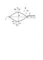
- the snare loop of the endoscope snare described in Patent Document 1 has a first main bent portion, a second main bent portion, and a third main bent portion in order from the distal end side, and has a hexagonal shape. Is formed.
- the proximal end side of the snare loop of the endoscope snare described in Patent Document 1 is bound by a connecting pipe and is inserted into the sheath so as to be able to advance and retreat.
- the snare loop 100 of the endoscope snare described in Patent Document 1 has a length A from the first main bent portion 11 to the second main bent portion 12 and a second main bent portion 12. Of the length B from the bent portion 12 to the third main bent portion 13 and the length C from the third main bent portion 13 to the rear end binding portion 3, the third main bent portion 13 to the rear end The length C to the binding part 3 is the longest. More specifically, in the snare loop 100 of the endoscope snare described in Patent Document 1, the length A is 2 times to 3 times the length B, and the length C is 5 times to 10 times the length A. It is formed in less than double.
- the snare for an endoscope described in Patent Document 1 can be captured and excised from a small polyp to a large polyp by adjusting the size of the snare loop 100.
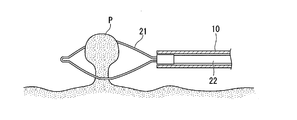
- the operator When performing a treatment on a large polyp using the endoscope snare described in Patent Document 1, as shown in FIG. 10, the operator removes the snare loop 100 of the endoscope snare from the distal end of the sheath 102. When protruding, the snare loop 100 swells greatly due to its own elasticity. In this state, the surgeon can capture the polyp by applying the snare loop 100 to the polyp. At this time, since the length C from the third main bent portion 13 of the snare loop to the rear end bundling portion 3 is long, the snare loop 100 has a configuration in which the entire length becomes long and gently spreads.
- the change in the opening width of the snare loop 100 accompanying the operation of the surgeon becomes relatively gradual.
- the tissue to be excised may be excised by the operator's operation, and normal tissue that is not desired to be excised may be excised.
- the operator pulls the operation wire 104 toward the proximal end side of the sheath 102.
- the size of the snare loop 100 needs to be adjusted.
- the size of the snare loop 100 since the total length of the snare loop 100 is long, there is a possibility that many normal tissues that are not desired to be excised enter the snare loop 100 in this process.
- the present invention provides an endoscopic treatment tool that can finely adjust the opening width of the snare loop and can be excised with an appropriate excision range and excision amount for the tissue to be excised. Objective.
- An endoscope treatment tool includes a sheath that can be inserted into a channel of an endoscope, and a long portion that is inserted into the sheath so as to be able to advance and retreat in its longitudinal axis direction.
- the wire is arranged at the tip of the long portion and is bent into a loop shape, and can be deformed so that the size of the loop changes by projecting and retracting from the sheath by advancing and retracting the long portion.
- a loop portion wherein the loop portion includes a first bent portion, a pair of second bent portions, a pair of third bent portions, and a fourth bent portion in order from the distal end toward the proximal end.
- the length of the proximal wire portion connecting the pair of third bent portions and the fourth bent portion is longer than the length of the distal wire portion connecting the first bent portion and the pair of second bent portions.
- the tip wire portion is long and the pair of second bent portions and the pair of third bent portions are Longer than the length of the intermediate wire portion connecting the first and second bent portions from the first bent portion in the longitudinal axis direction in a state in which the loop portion protrudes from the sheath to the maximum by the advance and retreat operation of the long portion.
- the first length that is up to 1.5 times is not less than 1.5 times the first width that is the maximum dimension of the loop portion in the direction orthogonal to the longitudinal axis, and the proximal wire portion
- the length of the intermediate wire portion is not less than 40% and not more than 60% of the first length, and the length of the intermediate wire portion is not less than 20% and not more than 30% of the first width.
- a state where 2/3 of the first length of the loop portion protrudes from the sheath a state where 2/3 of the first length of the loop portion protrudes from the sheath.
- the dimension of the loop part in the direction orthogonal to the longitudinal axis may be 40% or more and less than 60% of the first width.
- an intermediate position of the loop part is arranged in the intermediate wire part in the longitudinal axis direction of the loop part. May be.
- the loop portion has a distal-end bending angle formed by the distal-end wire portion and the intermediate wire portion, It may be larger than the bending angle on the base end side formed by the intermediate wire portion and the base end wire portion.
- the open width of the snare loop can be finely adjusted, and the tissue to be excised can be excised with an appropriate excision range and excision amount.
- FIG. 2B is an enlarged view showing a partial configuration of the snare loop in FIG. 2A. It is a figure which shows operation
- FIGS. 1 to 5 an endoscope treatment tool according to an embodiment of the present invention will be described with reference to FIGS. 1 to 5.
- FIG. 1 is a diagram showing an overall configuration of an endoscope treatment tool according to the present embodiment.
- FIG. 2A is a diagram illustrating a configuration of a snare loop of the endoscope treatment tool according to the present embodiment.
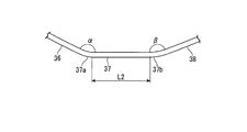
- 2B is an enlarged view showing a configuration of a part of the snare loop of the endoscope treatment tool according to the present embodiment, and is an enlarged view of a portion surrounded by a two-dot chain line in FIG. 2A.
- FIG. 3 is a diagram illustrating an operation when using the endoscope treatment tool according to the present embodiment.
- FIG. 4 is a diagram illustrating an operation of drawing a part of the snare loop of the endoscope treatment tool according to the present embodiment into the sheath.
- FIG. 5 is a diagram illustrating an operation when using the endoscope treatment tool according to the present embodiment.
- the endoscope treatment tool 1 according to the present embodiment includes a sheath 10, a snare wire 20, and an operation unit 40.
- the sheath 10 of the endoscope treatment tool 1 extends along the longitudinal axis X, and is formed in a long shape so that it can be inserted into a body cavity.
- the sheath 10 is made of an insulating material, for example, a fluororesin such as PTFE (polytetrafluoroethylene).
- the sheath 10 has flexibility, and is formed so as to be able to be inserted into and removed from a treatment instrument channel (not shown) of an endoscope along a curved shape such as a luminal tissue in a body cavity.
- the snare wire 20 includes a loop portion 21 provided on the distal end side and an operation wire (long portion) 22 provided on the proximal end side.
- the snare wire 20 is conductive and can be energized with a high-frequency current.
- the snare wire 20 according to the present embodiment is formed by bending a single elastic wire, for example, a stranded wire of a stainless steel wire, it can be repeatedly deformed. Therefore, the surgeon can perform an operation of re-grabbing the resection object using the snare wire 20 and an operation of sequentially capturing a plurality of different resection objects using the snare wire 20.
- the snare wire 20 according to the present embodiment is formed with a wire diameter of about 0.3 mm, and is thinner than the conventional high-frequency dedicated snare wire 0.47 mm. Therefore, the surgeon can perform both treatments by excising the tissue by applying a high-frequency current to the snare wire 20 and excising the tissue by binding the tissue with the snare wire 20 without applying the high-frequency current. .
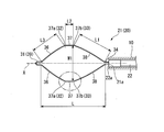
- the loop portion 21 on the distal end side of the snare wire 20 is a substantially hexagonal loop formed symmetrically with respect to the longitudinal axis X of the sheath 10.
- the loop portion 21 includes a first bent portion 31, a pair of second bent portions 32, a pair of third bent portions 33, and a fourth bent portion 34 in order from the distal end side toward the proximal end side.
- Each of the first bent portion 31, the pair of second bent portions 32, the pair of third bent portions 33, and the fourth bent portion 34 is bent convexly outwardly of the loop shape formed by the loop portion 21. Configured.
- the fourth bent portion 34 provided at the proximal end 21 a of the loop portion 21 is connected to the distal end 22 a of the operation wire 22.
- the first bent portion 31 has a protrusion 39 formed by bending an elastic wire.
- the shape of the protrusion 39 of the loop portion 21 does not change even when the loop portion 21 is advanced or retracted from the distal end opening of the sheath 10.
- the projection 39 opens the loop portion 21 against the pushing force acting on the loop portion 21.
- the loop portion 21 includes a pair of distal wire portions 36, a pair of intermediate wire portions 37, and a pair of proximal wire portions 38 in order from the distal end side toward the proximal end side.
- the pair of tip wire portions 36 is a region of the snare wire 20 provided between the first bent portion 31 and the pair of second bent portions 32.
- the pair of intermediate wire portions 37 is a region of the snare wire 20 provided between the pair of second bent portions 32 and the pair of third bent portions 33.
- the pair of proximal end wire portions 38 is a region of the snare wire 20 provided between the pair of third bent portion 33 and the fourth bent portion 34.
- the pair of intermediate wire portions 37 of the loop portion 21 are substantially parallel to each other.
- the length of the proximal wire portion 38 is defined as L1
- the length of the intermediate wire portion 37 is defined as L2
- the length of the distal wire portion 36 is defined as L3.
- the intermediate wire portion 37 of the loop portion 21 of the endoscope treatment tool 1 has a distal end portion 37a and a proximal end portion 37b.
- the distal end portion 37 a of the intermediate wire portion 37 is a connecting portion between the intermediate wire portion 37 and the distal wire portion 36.
- the proximal end portion 37 b of the intermediate wire portion 37 is a connecting portion between the intermediate wire portion 37 and the proximal end wire portion 38.
- the loop portion 21 protrudes completely from the opening formed at the distal end of the sheath 10. At that time, as a result of the loop part 21 expanding due to the elasticity of the elastic wire, the loop part 21 has the largest loop-shaped area formed by the loop part 21. In this state, along the longitudinal axis X of the sheath 10, the distance from the fourth bent portion on the proximal end side of the loop portion 21 to the first bent portion 31 on the distal end side is determined in the longitudinal axis direction of the loop portion 21. It is defined as a length (first length) L.
- the opening width of the loop portion 21 in the direction orthogonal to the longitudinal axis X of the sheath 10 is set to the maximum opening width of the loop portion 21.
- the maximum opening width W ⁇ b> 1 of the loop portion 21 is substantially equal to the distance between the pair of intermediate wire portions 37.
- the length L in the longitudinal axis direction of the loop portion 21 is the maximum opening of the loop portion 21 in a state where the loop portion 21 is completely projected from the opening provided at the distal end of the sheath 10.
- the width W1 is 1.5 to 2 times the width W1.
- the length L1 of the proximal end wire portion 38 is set longer than the length L3 of the distal end wire portion 36.
- the length L3 of the tip wire portion 36 is set longer than the length L2 of the intermediate wire portion 37. That is, in the loop portion 21 according to the present embodiment, the length L1 of the proximal end wire portion 38, the length L2 of the intermediate wire portion 37, and the length L3 of the distal end wire portion 36 are in a relationship of L1> L3> L2. Meet.
- the length L1 of the proximal end wire portion 38 is not less than 40% and not more than 60% of the length L in the longitudinal axis direction of the loop portion 21, and the length L2 of the intermediate wire portion 37 is The maximum opening width W1 of the loop portion 21 is 20% or more and 30% or less.
- Each configuration of the endoscope treatment tool 1 according to the present embodiment may be appropriately selected in accordance with an actual use situation as long as the above dimensional relationship is satisfied.
- Each configuration of the loop portion 21 of the endoscope treatment tool 1 according to the present embodiment may be formed with an appropriate dimensional change width in accordance with an actual use situation and a manufacturing process.
- the tip wire portion 36 and the intermediate wire portion 37 are connected adjacent to each other.
- the adjacent tip wire portion 36 and the intermediate wire portion 37 form a tip end side bending angle ⁇ .
- the adjacent intermediate wire portion 37 and the proximal end wire portion 38 form a proximal end side bending angle ⁇ .
- the distal end side bending angle ⁇ is larger than the proximal end side bending angle ⁇ .
- the intermediate position of the loop portion 21 may be arranged in the intermediate wire portion 37 along the direction of the longitudinal axis X of the sheath 10.
- a portion of the substantially hexagonal shape of the loop portion 21 whose length in the longitudinal axis direction is L / 2 may be located in the intermediate wire portion 37.
- the operation unit 40 of the present embodiment includes an operation unit main body 41 connected to the proximal end portion of the sheath 10, a slider 42 attached to the operation unit main body 41, and a connector 43.
- the operation wire 22 is connected to the slider 42. Therefore, the snare wire 20 is moved back and forth with respect to the sheath 10 by moving the slider 42 forward and backward with respect to the operation unit main body 41.
- the loop portion 21 protrudes from the opening provided at the distal end of the sheath 10.
- the loop portion 21 is sequentially accommodated in the sheath 10.
- the connector 43 can be connected to a high frequency power supply device (not shown), and can supply a high frequency current to the operation wire 22. Since the operation wire 22 is electrically connected to the loop portion 21, the high frequency current supplied from the high frequency power supply device is transmitted to the loop portion 21 through the operation wire 22.
- the operator inserts the endoscope into the patient's body cavity by a known technique, guides the distal end of the endoscope to the position of the polyp P to be excised, and places the polyp P in the field of view of the endoscope. Capture. Then, the operator inserts the endoscope treatment tool 1 according to the present embodiment into the endoscope and protrudes from the opening on the distal end side of the endoscope, and then, as shown in FIG. Forty sliders 42 are slid to the front end side with respect to the operation unit main body 41.
- the surgeon hangs the loop portion 21 on the polyp P in the first state. Subsequently, the surgeon slides the slider 42 of the operation unit 40 toward the proximal end side with respect to the operation unit main body 41. As a result, the proximal end side of the loop portion 21 is drawn into the sheath 10, and the root of the polyp P is bound by the loop portion 21.
- the operator After the root of the polyp P is bound by the loop portion 21, the operator operates a high-frequency power supply device (not shown) to supply a high-frequency current to the endoscope treatment tool 1.
- a high frequency flows through the loop portion 21, the polyp P tightly bound by the loop portion 21 is excised while being cauterized.
- the snare wire 20 according to the present embodiment is formed thin, for example, with a wire diameter of about 0.3 mm. Therefore, the surgeon can cut off the polyp P by an operation of moving the loop portion 21 further to the proximal end side in a state where the root of the polyp P is tightly bound by the loop portion 21 without flowing high-frequency current.
- the operator adjusts the loop portion 21 from the first state to a state in which the size of the loop shape formed by the loop portion 21 matches the size of the polyp P.
- the operator slides the slider 42 of the operation unit 40 toward the proximal end side with respect to the operation unit main body 41, and a part of the proximal end side of the loop portion 21 is attached to the sheath 10. Pull in.
- the left side of FIG. 4 shows an operation in which the loop portion 21 of the snare wire 20 of the endoscope treatment tool 1 according to the present embodiment is drawn into the sheath 10.
- the opening width of the loop portion 21 is the first width. From W1, the second opening width (second width) W2, the third opening width (third width) W3, and the fourth opening width (fourth width) W4 decrease in this order.
- W1 the second opening width (second width) W2
- W3 the third opening width (third width) W3
- W4 the fourth opening width (fourth width) W4 decrease in this order.
- the opening width of the loop portion is changed from the first width W1 to the fifth opening width ( The fifth width W5, the sixth opening width (sixth width) W6, and the seventh opening width (seventh width) W7 are reduced in this order.
- the fifth width W5 is smaller than the second width W2
- the sixth width W6 is smaller than the third width W3
- the seventh width W7 is smaller than the fourth width W4.
- the pair of distal wire portions 36, the pair of intermediate wire portions 37, and the pair of proximal end wire portions 38 move toward the proximal end side.
- the opening width of the loop shape formed by the loop portion 21 is reduced.
- the proximal end portion 37 b of the intermediate wire portion 37 moves to the proximal end side in the direction of the longitudinal axis X by pulling the proximal end wire portion 38, while the longitudinal axis of the sheath 10 in the direction orthogonal to the longitudinal axis X.
- Approach X is
- the distal end portion 37 a of the intermediate wire portion 37 moves away from the longitudinal axis X of the sheath 10 in the direction orthogonal to the longitudinal axis X while moving to the proximal end side in the longitudinal axis X direction by pulling the proximal end wire portion 38.
- the proximal end side bending angle ⁇ formed by the intermediate wire portion 37 and the proximal end wire portion 38 increases, and the distal end side bending formed by the distal end wire portion 36 and the intermediate wire portion 37.
- the angle ⁇ decreases.
- the loop portion 21 protruding from the opening on the distal end side of the sheath 10 is The shape is substantially rhombus (second state).
- the fourth opening width W4 which is the opening width of the loop portion 21 in the direction perpendicular to the longitudinal axis X of the sheath, is 40% or more and less than 60% of the first width W1 of the loop portion 21.
- the proximal-side bending angle ⁇ formed by the intermediate wire portion 37 and the proximal wire portion 38 becomes approximately 180 degrees, and the distal wire portion 36 and the intermediate wire portion 37 are The leading end side bending angle ⁇ is the minimum value.
- the proximal end portion 37 b of the intermediate wire portion 37 is located outside the sheath 10.
- the open width of the loop portion of the snare wire W7 is not less than 30% and not more than 35% of the first width W1 of the loop. That is, in the snare wire that does not have the intermediate wire portion 37, it can be confirmed that the opening width of the loop is drastically reduced as a result of drawing the snare wire toward the proximal end at about L / 3.
- the surgeon hangs the loop portion 21 in the second state on the polyp P. Thereafter, as in the case where the polyp P described above is large, the surgeon passes a high-frequency current through the loop portion 21 and excises the polyp P that is bound by the loop portion 21. The surgeon can also remove the polyp P by an operation of moving the loop portion 21 further to the proximal end side in a state where the root of the polyp P is tightly bound by the loop portion 21 without flowing high-frequency current. In the present embodiment, it has been described that the surgeon hangs the loop portion 21 in the second state on the polyp P. However, within the range of the first width W1 to the fourth width W4 according to the actual size of the polyp P. Thus, the operator can appropriately adjust the opening width of the loop portion 21 by the operation of retracting the loop portion 21.
- surgeon takes out the polyp P after excision from the body using a known tissue collecting device (not shown), pulls out the endoscope treatment tool 1 from the body cavity, and completes a series of treatments.
- the length L in the longitudinal axis direction is 1.5 to 2 times the first width W1 of the loop portion 21, And the relationship of L1>L3> L2 is satisfied.
- the length L1 of the proximal end wire portion 38 is 40% or more and 60% or less of the first length L of the loop portion 21.
- the opening width of the snare loop when adjusting the opening width of the snare loop, there is a possibility that a lot of normal tissue that is not desired to be removed enters the snare loop.
- the length of the loop portion is short, in order to secure an opening width in accordance with the size of the polyp P, it is necessary to attach a crease that bends the elastic wire greatly outward from the axial direction of the sheath of the endoscope treatment instrument. There is. In such a case, when the loop portion is hung on the polyp P and pulled into the sheath of the treatment instrument for endoscope, the opening width of the loop portion may rapidly decrease.
- the loop portion 21 since the length L of the loop portion 21 can be suppressed from being excessively long, the loop portion 21 is pushed out from the opening on the distal end side of the endoscope. As a result, it is possible to maintain the force necessary to press against the tissue and to form a loop shape close to a circle according to the shape of the polyp P.
- the loop portion 21 is drawn into the sheath 10.
- the opening width of the loop portion 21 can be prevented from being rapidly reduced. That is, according to the endoscope treatment tool 1 according to the present embodiment, it is possible to prevent the loop shape formed by the loop portion 21 from abruptly narrowing.
- the length L2 of the intermediate wire portion 37 is 20% or more and 30% or less of the first width W1 of the loop portion 21.
- the distal end portion 37a of the intermediate wire portion 37 is separated from the longitudinal axis X of the sheath 10, a reduction in the opening width of the loop portion 21 is partially absorbed. To do. In other words, the movement of the distal end portion 37a of the intermediate wire portion 37 can absorb the decrease in the distance (spread) between the pair of distal end wire portions 36 as the opening width of the loop portion 21 decreases. As a result, as shown in FIG.
- the present embodiment when the loop portion of the endoscope treatment tool is pulled to the proximal end side with the same length as compared with the endoscope treatment tool that does not have the intermediate wire portion 37, the present embodiment
- the decreasing rate of the opening width of the loop portion 21 according to the above becomes moderate.
- the fourth width W4 of the loop portion 21 is the first width of the loop portion 21. It is 40% or more and less than 60% of the width W1.
- the length L2 of the intermediate wire portion 37 according to the present embodiment is preferably 20% or more and 30% or less of the first width W1 of the loop portion 21.
- the first length L of the loop portion 21 is the same as that for a conventional endoscope. It can be reduced by about 30% compared to the treatment tool.
- the distal-side bending angle ⁇ is larger than the proximal-side bending angle ⁇ in the intermediate wire portion 37 of the loop portion 21. Since the endoscope treatment tool 1 has this configuration, the length L3 of the distal wire portion 36 is increased. As a result, when the loop portion 21 is drawn into the sheath 10, the reduction rate of the opening width of the loop portion 21 becomes more gradual, and the opening width of the loop portion 21 can be easily maintained. Therefore, it is easier for the surgeon to perform an operation of adjusting the opening width of the loop portion 21.
- Modification 1 A first modification of the present invention will be described with reference to FIGS.
- the endoscope treatment tool according to this modification is different from the above-described embodiment in the configuration of the loop portion of the snare wire.
- the same components as those described above are denoted by the same reference numerals, and redundant description is omitted.
- the endoscope treatment tool 1A according to this modification includes a first bent portion 31A instead of the first bent portion 31 of the snare wire 20 of the endoscope treatment tool 1 according to the above-described embodiment.
- the loop portion 21A of the snare wire 20A of the endoscope treatment tool 1A according to this modification includes a first bent portion 31A, a pair of second bent portions 32, and a pair of third bent portions. 33 and a fourth bent portion 34.
- the first bent portion 31A of the endoscope treatment tool 1A according to this modification does not have the projection 39 of the first bent portion 31 according to the above-described embodiment, and a pair of The tip wire portion 36 is connected at an acute angle.
- the endoscope treatment tool 1A according to the present modification extends along the longitudinal axis X of the sheath 10 from the fourth bent portion 34 on the proximal end side of the loop portion 21A to the first bent portion 31A on the distal end side.
- the distance is defined as a length (first length) L in the longitudinal axis X direction of the loop portion 21A.
- L is 1.5 to 2 times the first width W1 of the loop portion 21A.
- the length L1 of the proximal wire portion 38 and the length L2 of the intermediate wire portion 37 are the same as those of the endoscope treatment tool 1 according to the above-described embodiment.
- the length L3 of the tip wire portion 36 satisfies the relationship of L1>L3> L2.
- the length L1 of the proximal end wire portion 38 is 40% or more and 60% or less of the length L in the longitudinal axis direction of the loop portion 21A.
- the length L2 of the portion 37 is 20% or more and 30% or less of the first width W1 of the loop portion 21.
- the loop portion 21A of the endoscope treatment tool 1A is compared with an endoscope treatment tool that does not have the intermediate wire portion 37.
- the decreasing rate of the opening width of the loop portion 21A becomes gradual. That is, according to the endoscope treatment tool 1A according to the present modification, when the operator pulls the loop portion 21A into the sheath 10, it is possible to suppress a sudden decrease in the opening width of the loop portion 21A.
- Modification 2 A second modification of the present invention will be described with reference to FIG. In the following description, the same components as those described above are denoted by the same reference numerals, and redundant description is omitted.
- the pair of intermediate wire portions 37 are formed in a substantially parallel state.
- the endoscope treatment tool 1B according to the present modification may be formed in a state where the pair of intermediate wire portions 57 are not parallel to each other.
- the pair of intermediate wire portions 57 are formed symmetrically about the longitudinal axis X of the sheath 10.
- the pair of intermediate wire portions 57 are formed to extend outward from the longitudinal axis X of the sheath 10 from the distal end portion 57a toward the proximal end portion 57b. Yes.
- the distance between the pair of proximal end portions 57b is larger than the distance between the pair of distal end portions 57a.
- the distance between the pair of proximal end portions 57b is defined as the maximum opening width (first width) W1 ′ of the loop portion 21B of the endoscope treatment instrument 1B. .
- the length L2 ′ of the intermediate wire portion 57 is 20% or more and 30% of the first width W1 ′ of the loop portion 21B, as in the above-described embodiment of the present invention. It is as follows. Moreover, about the other structure of the treatment tool 1B for endoscopes which concerns on this modification, you may be comprised similarly to each structure of the above-mentioned embodiment of this invention.
- the endoscope treatment tool 1B according to the present modification has the above-described configuration, so that the loop portion 21B of the endoscope treatment tool 1B is proximally moved to the proximal end 10 as in the above-described embodiment of the present invention.
- the distance between the pair of proximal end portions 57b is larger than the distance between the pair of distal end portions 57a.
- an endoscopic treatment tool that can finely adjust the open width of the snare loop and can be excised with an appropriate excision range and excision amount for the tissue to be excised. Can do.
Landscapes
- Health & Medical Sciences (AREA)
- Surgery (AREA)
- Life Sciences & Earth Sciences (AREA)
- Engineering & Computer Science (AREA)
- Molecular Biology (AREA)
- Public Health (AREA)
- Heart & Thoracic Surgery (AREA)
- Medical Informatics (AREA)
- Nuclear Medicine, Radiotherapy & Molecular Imaging (AREA)
- Animal Behavior & Ethology (AREA)
- General Health & Medical Sciences (AREA)
- Biomedical Technology (AREA)
- Veterinary Medicine (AREA)
- Cardiology (AREA)
- Physics & Mathematics (AREA)
- Plasma & Fusion (AREA)
- Otolaryngology (AREA)
- Surgical Instruments (AREA)
Priority Applications (2)
| Application Number | Priority Date | Filing Date | Title |
|---|---|---|---|
| CN201880035034.0A CN110678131B (zh) | 2017-06-13 | 2018-04-17 | 内窥镜用处置器具 |
| US16/699,947 US11096714B2 (en) | 2017-06-13 | 2019-12-02 | Endoscopic treatment tool |
Applications Claiming Priority (2)
| Application Number | Priority Date | Filing Date | Title |
|---|---|---|---|
| JP2017115905A JP6761378B2 (ja) | 2017-06-13 | 2017-06-13 | 内視鏡用処置具 |
| JP2017-115905 | 2017-06-13 |
Related Child Applications (1)
| Application Number | Title | Priority Date | Filing Date |
|---|---|---|---|
| US16/699,947 Continuation US11096714B2 (en) | 2017-06-13 | 2019-12-02 | Endoscopic treatment tool |
Publications (1)
| Publication Number | Publication Date |
|---|---|
| WO2018230145A1 true WO2018230145A1 (ja) | 2018-12-20 |
Family
ID=64660976
Family Applications (1)
| Application Number | Title | Priority Date | Filing Date |
|---|---|---|---|
| PCT/JP2018/015860 Ceased WO2018230145A1 (ja) | 2017-06-13 | 2018-04-17 | 内視鏡用処置具 |
Country Status (4)
| Country | Link |
|---|---|
| US (1) | US11096714B2 (enExample) |
| JP (1) | JP6761378B2 (enExample) |
| CN (1) | CN110678131B (enExample) |
| WO (1) | WO2018230145A1 (enExample) |
Cited By (2)
| Publication number | Priority date | Publication date | Assignee | Title |
|---|---|---|---|---|
| CN110584749A (zh) * | 2019-09-30 | 2019-12-20 | 南微医学科技股份有限公司 | 一种用于组织切除的圈套器 |
| CN115342120A (zh) * | 2021-05-13 | 2022-11-15 | 达运精密工业股份有限公司 | 折合式金属背板 |
Families Citing this family (3)
| Publication number | Priority date | Publication date | Assignee | Title |
|---|---|---|---|---|
| JP6761378B2 (ja) * | 2017-06-13 | 2020-09-23 | オリンパス株式会社 | 内視鏡用処置具 |
| USD1079002S1 (en) * | 2020-10-21 | 2025-06-10 | Ohio State Innovation Foundation | Scalpel |
| TW202506076A (zh) * | 2023-05-19 | 2025-02-16 | 日商特線工業股份有限公司 | 圈套器導絲構造體 |
Citations (5)
| Publication number | Priority date | Publication date | Assignee | Title |
|---|---|---|---|---|
| JPH08299349A (ja) * | 1995-05-12 | 1996-11-19 | Olympus Optical Co Ltd | 内視鏡用処置具 |
| JPH11123198A (ja) * | 1997-10-23 | 1999-05-11 | Asahi Optical Co Ltd | 内視鏡用スネア |
| JP2001292960A (ja) * | 2000-04-12 | 2001-10-23 | Asahi Optical Co Ltd | 内視鏡用スネア |
| US20050085808A1 (en) * | 2003-10-16 | 2005-04-21 | Nakao Naomi L. | Medical instrument with indented loop and associated method |
| JP2010505450A (ja) * | 2006-10-02 | 2010-02-25 | 株式会社メディコスヒラタ | 内視鏡用スネア |
Family Cites Families (13)
| Publication number | Priority date | Publication date | Assignee | Title |
|---|---|---|---|---|
| GB2011258A (en) * | 1977-11-18 | 1979-07-11 | Wolf Gmbh Richard | Device for removing excrescences and polyps |
| US5059199A (en) * | 1989-04-12 | 1991-10-22 | Olympus Optical Co., Ltd. | Treating device for endoscopes |
| JPH0871082A (ja) | 1994-09-08 | 1996-03-19 | Olympus Optical Co Ltd | 内視鏡用高周波切開切除具 |
| JP3974232B2 (ja) * | 1997-09-10 | 2007-09-12 | ペンタックス株式会社 | 内視鏡用スネア |
| JP2000083964A (ja) | 1998-09-14 | 2000-03-28 | Asahi Optical Co Ltd | 内視鏡用ワイヤループ型処置具 |
| JP2000083963A (ja) | 1998-09-14 | 2000-03-28 | Asahi Optical Co Ltd | 内視鏡用スネア |
| CA2402407C (en) * | 2001-01-08 | 2012-06-19 | Scimed Life Systems, Inc. | Retrieval basket with releasable tip |
| US20090024138A1 (en) * | 2007-07-18 | 2009-01-22 | Rafic Saleh | Surgical retrieval device radially deployable from collapsed position to a snare or cauterization loop |
| JP2014230659A (ja) * | 2013-05-29 | 2014-12-11 | 国立大学法人 香川大学 | スネア |
| JP6204085B2 (ja) | 2013-06-27 | 2017-09-27 | オリンパス株式会社 | 内視鏡用処置具および内視鏡システム |
| EP3269316A4 (en) | 2015-03-13 | 2018-11-21 | Olympus Corporation | Treatment instrument |
| EP4257075A3 (en) * | 2017-01-09 | 2023-11-22 | United States Endoscopy Group, Inc. | Retrieval device |
| JP6761378B2 (ja) * | 2017-06-13 | 2020-09-23 | オリンパス株式会社 | 内視鏡用処置具 |
-
2017
- 2017-06-13 JP JP2017115905A patent/JP6761378B2/ja active Active
-
2018
- 2018-04-17 WO PCT/JP2018/015860 patent/WO2018230145A1/ja not_active Ceased
- 2018-04-17 CN CN201880035034.0A patent/CN110678131B/zh active Active
-
2019
- 2019-12-02 US US16/699,947 patent/US11096714B2/en active Active
Patent Citations (5)
| Publication number | Priority date | Publication date | Assignee | Title |
|---|---|---|---|---|
| JPH08299349A (ja) * | 1995-05-12 | 1996-11-19 | Olympus Optical Co Ltd | 内視鏡用処置具 |
| JPH11123198A (ja) * | 1997-10-23 | 1999-05-11 | Asahi Optical Co Ltd | 内視鏡用スネア |
| JP2001292960A (ja) * | 2000-04-12 | 2001-10-23 | Asahi Optical Co Ltd | 内視鏡用スネア |
| US20050085808A1 (en) * | 2003-10-16 | 2005-04-21 | Nakao Naomi L. | Medical instrument with indented loop and associated method |
| JP2010505450A (ja) * | 2006-10-02 | 2010-02-25 | 株式会社メディコスヒラタ | 内視鏡用スネア |
Cited By (3)
| Publication number | Priority date | Publication date | Assignee | Title |
|---|---|---|---|---|
| CN110584749A (zh) * | 2019-09-30 | 2019-12-20 | 南微医学科技股份有限公司 | 一种用于组织切除的圈套器 |
| CN110584749B (zh) * | 2019-09-30 | 2024-04-30 | 南微医学科技股份有限公司 | 一种用于组织切除的圈套器 |
| CN115342120A (zh) * | 2021-05-13 | 2022-11-15 | 达运精密工业股份有限公司 | 折合式金属背板 |
Also Published As
| Publication number | Publication date |
|---|---|
| JP2019000215A (ja) | 2019-01-10 |
| US11096714B2 (en) | 2021-08-24 |
| US20200100807A1 (en) | 2020-04-02 |
| CN110678131A (zh) | 2020-01-10 |
| CN110678131B (zh) | 2022-05-31 |
| JP6761378B2 (ja) | 2020-09-23 |
Similar Documents
| Publication | Publication Date | Title |
|---|---|---|
| WO2018230145A1 (ja) | 内視鏡用処置具 | |
| JP6072384B1 (ja) | 処置具 | |
| EP2000105A2 (en) | Endoscopic treatment tool | |
| US20130211415A1 (en) | Steerable tissue manipulation medical devices and related methods of use | |
| JP2010505450A (ja) | 内視鏡用スネア | |
| JP2000083963A (ja) | 内視鏡用スネア | |
| WO2013119970A1 (en) | Cutting tool with circulating wire | |
| US20140276910A1 (en) | Retrieval device and related methods of use | |
| US10092307B2 (en) | Tissue grasping tool | |
| US20150100062A1 (en) | Resection device having support elements and related methods of use | |
| US7404817B2 (en) | High-frequency incision device | |
| JP5098024B2 (ja) | 内視鏡用高周波処置具 | |
| US20140222014A1 (en) | Surgical Snare Device | |
| US11083483B2 (en) | Tissue excision instrument | |
| JP4512723B2 (ja) | 内視鏡用スネア | |
| JP2019097907A (ja) | 内視鏡用スネア | |
| JPH08299349A (ja) | 内視鏡用処置具 | |
| JP2002253559A (ja) | 内視鏡用ワイヤループ型処置具 | |
| JP4320194B2 (ja) | 内視鏡用高周波メス | |
| JP4589511B2 (ja) | 内視鏡用高周波スネア | |
| JP4761597B2 (ja) | 内視鏡用高周波スネア | |
| JP2023140245A (ja) | 内視鏡用スネア | |
| JPH0546426Y2 (enExample) | ||
| WO2022070438A1 (ja) | 把持鉗子 | |
| JP2007330664A (ja) | 止血具 |
Legal Events
| Date | Code | Title | Description |
|---|---|---|---|
| 121 | Ep: the epo has been informed by wipo that ep was designated in this application |
Ref document number: 18816966 Country of ref document: EP Kind code of ref document: A1 |
|
| NENP | Non-entry into the national phase |
Ref country code: DE |
|
| 122 | Ep: pct application non-entry in european phase |
Ref document number: 18816966 Country of ref document: EP Kind code of ref document: A1 |