WO2018225513A1 - 中継装置、中継方法及び中継プログラム - Google Patents
中継装置、中継方法及び中継プログラム Download PDFInfo
- Publication number
- WO2018225513A1 WO2018225513A1 PCT/JP2018/019822 JP2018019822W WO2018225513A1 WO 2018225513 A1 WO2018225513 A1 WO 2018225513A1 JP 2018019822 W JP2018019822 W JP 2018019822W WO 2018225513 A1 WO2018225513 A1 WO 2018225513A1
- Authority
- WO
- WIPO (PCT)
- Prior art keywords
- communication
- relay
- state
- message
- communication lines
- Prior art date
- Legal status (The legal status is an assumption and is not a legal conclusion. Google has not performed a legal analysis and makes no representation as to the accuracy of the status listed.)
- Ceased
Links
Images

Classifications
-
- H—ELECTRICITY
- H04—ELECTRIC COMMUNICATION TECHNIQUE
- H04L—TRANSMISSION OF DIGITAL INFORMATION, e.g. TELEGRAPHIC COMMUNICATION
- H04L12/00—Data switching networks
- H04L12/28—Data switching networks characterised by path configuration, e.g. LAN [Local Area Networks] or WAN [Wide Area Networks]
- H04L12/40—Bus networks
- H04L12/40169—Flexible bus arrangements
- H04L12/40176—Flexible bus arrangements involving redundancy
- H04L12/40182—Flexible bus arrangements involving redundancy by using a plurality of communication lines
-
- H—ELECTRICITY
- H04—ELECTRIC COMMUNICATION TECHNIQUE
- H04L—TRANSMISSION OF DIGITAL INFORMATION, e.g. TELEGRAPHIC COMMUNICATION
- H04L12/00—Data switching networks
- H04L12/28—Data switching networks characterised by path configuration, e.g. LAN [Local Area Networks] or WAN [Wide Area Networks]
- H04L12/40—Bus networks
- H04L12/40006—Architecture of a communication node
- H04L12/40013—Details regarding a bus controller
-
- H—ELECTRICITY
- H04—ELECTRIC COMMUNICATION TECHNIQUE
- H04L—TRANSMISSION OF DIGITAL INFORMATION, e.g. TELEGRAPHIC COMMUNICATION
- H04L12/00—Data switching networks
- H04L12/28—Data switching networks characterised by path configuration, e.g. LAN [Local Area Networks] or WAN [Wide Area Networks]
- H04L12/46—Interconnection of networks
-
- H—ELECTRICITY
- H04—ELECTRIC COMMUNICATION TECHNIQUE
- H04L—TRANSMISSION OF DIGITAL INFORMATION, e.g. TELEGRAPHIC COMMUNICATION
- H04L12/00—Data switching networks
- H04L12/66—Arrangements for connecting between networks having differing types of switching systems, e.g. gateways
-
- H—ELECTRICITY
- H04—ELECTRIC COMMUNICATION TECHNIQUE
- H04L—TRANSMISSION OF DIGITAL INFORMATION, e.g. TELEGRAPHIC COMMUNICATION
- H04L47/00—Traffic control in data switching networks
- H04L47/10—Flow control; Congestion control
- H04L47/29—Flow control; Congestion control using a combination of thresholds
-
- H—ELECTRICITY
- H04—ELECTRIC COMMUNICATION TECHNIQUE
- H04L—TRANSMISSION OF DIGITAL INFORMATION, e.g. TELEGRAPHIC COMMUNICATION
- H04L12/00—Data switching networks
- H04L12/28—Data switching networks characterised by path configuration, e.g. LAN [Local Area Networks] or WAN [Wide Area Networks]
- H04L12/40—Bus networks
- H04L2012/40208—Bus networks characterized by the use of a particular bus standard
- H04L2012/40215—Controller Area Network CAN
-
- H—ELECTRICITY
- H04—ELECTRIC COMMUNICATION TECHNIQUE
- H04L—TRANSMISSION OF DIGITAL INFORMATION, e.g. TELEGRAPHIC COMMUNICATION
- H04L12/00—Data switching networks
- H04L12/28—Data switching networks characterised by path configuration, e.g. LAN [Local Area Networks] or WAN [Wide Area Networks]
- H04L12/40—Bus networks
- H04L2012/40267—Bus for use in transportation systems
- H04L2012/40273—Bus for use in transportation systems the transportation system being a vehicle
-
- H—ELECTRICITY
- H04—ELECTRIC COMMUNICATION TECHNIQUE
- H04L—TRANSMISSION OF DIGITAL INFORMATION, e.g. TELEGRAPHIC COMMUNICATION
- H04L47/00—Traffic control in data switching networks
- H04L47/10—Flow control; Congestion control
- H04L47/12—Avoiding congestion; Recovering from congestion
- H04L47/125—Avoiding congestion; Recovering from congestion by balancing the load, e.g. traffic engineering
-
- H—ELECTRICITY
- H04—ELECTRIC COMMUNICATION TECHNIQUE
- H04L—TRANSMISSION OF DIGITAL INFORMATION, e.g. TELEGRAPHIC COMMUNICATION
- H04L47/00—Traffic control in data switching networks
- H04L47/10—Flow control; Congestion control
- H04L47/13—Flow control; Congestion control in a LAN segment, e.g. ring or bus
-
- H—ELECTRICITY
- H04—ELECTRIC COMMUNICATION TECHNIQUE
- H04L—TRANSMISSION OF DIGITAL INFORMATION, e.g. TELEGRAPHIC COMMUNICATION
- H04L49/00—Packet switching elements
- H04L49/50—Overload detection or protection within a single switching element
- H04L49/501—Overload detection
-
- H—ELECTRICITY
- H04—ELECTRIC COMMUNICATION TECHNIQUE
- H04L—TRANSMISSION OF DIGITAL INFORMATION, e.g. TELEGRAPHIC COMMUNICATION
- H04L49/00—Packet switching elements
- H04L49/50—Overload detection or protection within a single switching element
- H04L49/501—Overload detection
- H04L49/503—Policing
Definitions
- the present invention relates to a relay apparatus, a relay method, and a relay program that perform processing for relaying message transmission / reception between a plurality of communication lines.
- a gateway node connected to a plurality of CAN (Controller Area Network) buses is intended to suppress communication delay of important frames, occurrence of reception omission and transmission delay of low priority ID.
- a network system has been proposed.
- the gateway node monitors the load state of the CAN bus and adjusts the bus load according to the bus load state.
- the bus load is adjusted by reducing the relay processing by the gateway node, reducing the data length of the relay frame, increasing the frame transmission cycle by another node, or reducing the data length of the transmission frame.
- the CAN controller calculates the bus load factor of the network, determines the level of the network load based on the bus load factor, and transmits the communication message itself based on the determination result indicating that the load is high.
- Communication devices to be regulated have been proposed.
- a relay device to which a plurality of communication lines are connected is provided with a communication IC (Integrated Circuit) that transmits and receives messages for each communication line.
- a communication IC Integrated Circuit
- an unauthorized communication device is connected to a communication line, and the unauthorized communication device transmits a large number of messages to the communication line, thereby preventing a malicious attack such as preventing transmission and reception of messages by a legitimate communication device.
- a malicious attack such as preventing transmission and reception of messages by a legitimate communication device.
- the communication system is affected.
- the amount of communication is reduced according to the bus load, but it is difficult to cope with an attack in which an unauthorized communication device transmits a large number of messages.
- the present invention has been made in view of such circumstances, and an object of the present invention is to provide a relay device and a relay method capable of suppressing an increase in power consumption accompanying the operation of a communication IC or the like. It is in. Another object of the present invention is to provide a relay device, a relay method, and a relay program that can reduce the influence on the entire system due to an attack in which an unauthorized communication device transmits a large number of messages.
- the relay device is a relay device comprising a relay unit to which a plurality of communication lines are connected and a message received on one communication line is transmitted from another communication line to relay the message.
- a switch that switches to a connection state in which at least two communication lines included in the communication line are connected or a separation state in which the communication lines are individually separated, and the relay rule of the message by the relay unit is switched according to the switching state of the switch And a relay rule switching unit.
- the relay device includes a communication state detection unit that detects a communication state of the communication line, and switches the switch according to the communication state detected by the communication state detection unit.
- the communication state detection unit detects the amount of messages transmitted / received via the communication line, and the switch is connected when the amount of the messages is less than a predetermined amount. When the amount of the message exceeds a predetermined amount, the switch is switched to a separated state.
- the relay unit may receive a message received on a communication line in which the amount of messages detected by the communication state detection unit exceeds a second predetermined amount after the switch is switched to the separated state.
- a relay prohibiting unit that prohibits relaying to the communication line is provided.
- the relay device includes a storage unit that stores a plurality of pieces of relay information in which a message and a relay destination of the message are associated with each other, and any one from the storage unit according to a switching state of the switch.
- the relay rule of the message is switched by reading one relay information.
- a relay apparatus that relays the message by transmitting a message received on one communication line from another communication line includes the plurality of communication lines. It is switched to a connection state in which at least two communication lines included in the line are connected or to a separation state in which the communication lines are individually separated, and a message relay rule is switched according to the switching state.
- the relay program according to the present invention includes a relay unit that connects a plurality of communication lines, relays the message by transmitting a message received on one communication line from another communication line, and the plurality of the plurality of communication lines.
- a relay apparatus having a switch that switches to a connection state that connects at least two communication lines included in the communication line or a separation state that separates the communication lines individually, the switch is switched according to the communication state of the communication line, The relay rule of the message by the relay unit is switched according to the switching state of the switch.
- At least two communication lines included in a plurality of communication lines connected to the relay apparatus are switched using a switch to a connection state in which they are directly connected or a separation state in which they are individually separated.
- a directly connected communication line it is possible to send and receive messages without relaying messages by a relay device.
- the switch is switched to the connected state, the communication IC that transmits and receives messages to and from the communication line does not need to operate, and shifts to a low power consumption state such as a sleep state or a standby state. Can be reduced.
- the communication load can be distributed and reduced by individually setting the communication line in the separated state by the switch.
- the relay apparatus switches the message relay rule according to the network configuration, that is, according to the switch switching state.
- the relay apparatus stores a plurality of pieces of information such as a so-called routing map or a routing table in which a message is associated with a relay destination that relays the message, and any one of them according to the switching state of the switch.
- Message relay rules can be switched by relaying messages using relay information.
- the communication state of a communication line is detected and a switch is switched according to the detected communication state.
- the relay device detects a common communication state for a plurality of communication lines in a connected state, and individually detects a communication state for a communication line in a separated state.
- the communication state to be detected can be, for example, the amount of messages transmitted / received in a predetermined time. For example, when the message amount is less than a predetermined amount, the relay device switches the switch to connect the plurality of communication lines, and when the message amount exceeds the predetermined amount, the relay device is set to the separated state.
- the amount of messages is small, the power consumption of the communication IC is reduced by connecting multiple communication lines, and when the amount of messages is large, the communication load is distributed by separating the multiple communication lines. Can be reduced.
- the relay device detects the communication state of each separated communication line after switching the switch to the separated state because the message amount exceeds a predetermined amount.
- the relay device prohibits relaying a message received on this communication line to another communication line.
- the second predetermined amount may be the same value as or a different value from the predetermined amount serving as a switch switching determination criterion.
- an increase in power consumption associated with the operation of the communication IC or the like can be suppressed by providing a switch for switching a plurality of communication lines to a connected state. Further, in the case of the present invention, when the message amount of the communication line in the separated state exceeds the second predetermined amount, the relay of the message from this communication line is prohibited so that a large number of unauthorized communication devices can be obtained. It is possible to reduce the influence on the entire system by the attack of sending a message.
- FIG. 1 is a schematic diagram showing a configuration of a communication system according to the present embodiment.
- the communication system according to the present embodiment has a configuration in which a plurality of ECUs 2 mounted on a vehicle 1 indicated by broken lines transmit and receive messages via a plurality of communication lines 11 to 13 and a gateway 5 mounted on the vehicle 1. is there.
- the vehicle 1 is provided with a plurality of bus-type communication lines 11 to 13 at appropriate positions, and the communication lines 11 to 13 are connected to the gateway 5.
- One or a plurality of ECUs (Electronic Control Units) 2 are connected to each of the communication lines 11 to 13.
- the gateway 5 relays message transmission / reception between ECUs 2 connected to different communication lines 11 to 13 by relaying messages between the communication lines 11 to 13.
- the ECU 2 includes, for example, an ECU that controls the operation of the engine of the vehicle 1, an ECU that controls the locking / unlocking of the door, an ECU that controls the turning on / off of the light, an ECU that controls the operation of the airbag, and an ABS (Antilock Various ECUs such as an ECU for controlling the operation of the Brake System may be included.
- Each ECU 2 is connected to any one of the communication lines 11 to 13 arranged in the vehicle 1, and can send and receive messages to and from other ECUs 2 through the communication lines 11 to 13 and the gateway 5.
- the gateway 5 is connected to a plurality of communication lines 11 to 13 constituting the in-vehicle network of the vehicle 1 and performs a process of relaying message transmission / reception between the communication lines 11 to 13.
- three communication lines 11 to 13 are connected to the gateway 5, and three ECUs 2 are connected to each of the communication lines 11 to 13, respectively.
- the number of communication lines 11 to 13 connected to the gateway 5 and the number of ECUs 2 connected to the communication lines 11 to 13 are merely examples, and are not limited thereto.
- the gateway 5 can relay the message by transmitting the message received on any one of the communication lines 11 to 13 to the other communication lines 11 to 13.
- the ECU 2 and the gateway 5 transmit and receive messages in accordance with a CAN (Controller Area Network) communication protocol.
- the ECU 2 and the gateway 5 may be configured to transmit and receive messages according to a communication protocol other than CAN, for example, a communication protocol such as FlexRay or LIN (Local Interconnect Network).
- the ECU 2 and the gateway 5 may be configured to transmit and receive messages via at least a bus-type communication line.
- FIG. 2 is a schematic diagram showing the configuration of the gateway 5.
- the gateway 5 includes a control unit 50, communication units 51 to 53, a bus switching unit 55, and the like.
- CAN is adopted as a communication protocol
- communication lines 11 to 13 (so-called CAN bus) in the CAN communication protocol are two-wire.
- the communication line 11 is comprised by the two of the 1st communication line 11H and the 2nd communication line 11L
- the communication line 12 is comprised by the two of the 1st communication line 12H and the 2nd communication line 12L.
- the communication line 13 is composed of two lines, the first communication line 13H and the second communication line 13L.
- ECU 2 connected to the communication line 11 is identified as ECUs 2A and 2B
- ECU 2 connected to the communication line 12 is identified as ECUs 2C and 2D
- ECU 2 connected to the communication line 13 is identified as ECUs 2E and 2F.
- the communication line 11 is connected to the communication unit 51 of the gateway 5.
- the first communication line 11H and the second communication line 11L constituting the communication line 11 are connected in the vicinity of the communication unit 51 via the termination resistor R1.
- the communication lines 12 and 13 are respectively connected to the bus switching unit 55 of the gateway 5.
- the bus switching unit 55 has four switches SW1 to SW4, and the communication lines 12 and 13 are switched to either the communication line 11 or the communication units 52 and 53 by switching the switches SW1 to SW4. Selectively connect.
- the first communication line 12H of the communication line 12 is connected to the switch SW1 of the bus switching unit 55, and the first communication line 12H is connected to the first communication line 11H of the communication line 11 or the communication by switching the switch SW1.
- the second communication line 12L of the communication line 12 is connected to the switch SW2 of the bus switching unit 55, and the second communication line 12L is connected to the second communication line 11L of the communication line 11 or the communication by switching the switch SW2.
- the first communication line 13H of the communication line 13 is connected to the switch SW3 of the bus switching unit 55.
- the first communication line 13H is connected to the first communication line 11H of the communication line 11 or the communication unit 53 by switching the switch SW3.
- the second communication line 13L of the communication line 13 is connected to the switch SW4 of the bus switching unit 55.
- the second communication line 13L is connected to the second communication line 11L of the communication line 11 or the communication unit 53 by switching the switch SW4. Connected to either.
- the communication unit 52 is connected to the bus switching unit 55 via two communication lines, and the two communication lines are connected via a termination resistor R2.
- the communication unit 53 is connected to the bus switching unit 55 via two communication lines, and the two communication lines are connected via a termination resistor R3.
- the communication units 51 to 53 transmit the message by converting the message for transmission given from the control unit 50 into a differential signal and outputting it to the communication lines 11 to 13. Further, the communication units 51 to 53 receive a message by sampling and acquiring the potential difference of the communication lines 11 to 13, and give the received message to the control unit 50.
- the communication units 51 to 53 can be realized using, for example, an IC (Integrated Circuit) that transmits and receives a message based on a CAN communication standard, an IC such as a so-called CAN controller.
- the communication units 51 to 53 can switch between a normal operation state in which messages are transmitted and received and a power saving state in which power consumption is reduced without transmitting and receiving messages, under the control of the control unit 50.
- connection destinations of the four switches SW1 to SW4 of the bus switching unit 55 are switched according to a switching signal given from the control unit 50.
- the four switches SW1 to SW4 are switched in response to one switching signal from the control unit 50.
- the control unit 50 has four switches SW1.
- the switch SW4 may be switched individually.
- the bus switching unit 55 connects the communication lines 12 and 13 to the communication line 11 by switching the switches SW1 to SW4 to the communication line 11 side, and establishes a connection state in which the three communication lines 11 to 13 are directly connected. be able to.
- the bus switching unit 55 connects the communication lines 12 and 13 to the communication units 52 and 53, respectively, by switching the switches SW1 to SW4 to the communication units 52 and 53, and individually connects the three communication lines 11 to 13 to each other. A separated state connected to the communication units 51 to 53 can be established.
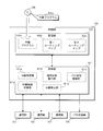
- FIG. 3 is a block diagram illustrating a configuration of the control unit 50.
- the control unit 50 includes a processing unit 61, a storage unit 62, and the like.
- the processing unit 61 is configured using an arithmetic processing device such as a CPU (Central Processing Unit) or an MPU (Micro-Processing Unit), and by reading and executing the relay program 62a stored in the storage unit 62, Arithmetic processing necessary for message relay processing and switching control processing of the bus switching unit 55 is performed.
- the processing unit 61 can exchange messages with the communication lines 11 to 13 by exchanging messages with the communication units 51 to 53.
- the processing unit 61 can output a switching signal to the bus switching unit 55 and switch the four switches SW1 to SW4 of the bus switching unit 55 to switch the communication lines 11 to 13 to the connected state or the separated state.
- the storage unit 62 is configured using a non-volatile memory element such as a flash memory or an EEPROM (Electrically Erasable Programmable Read Only Memory).
- the storage unit 62 stores a program executed by the processing unit 61 and data necessary for executing the program.
- the storage unit 62 stores a relay program 62a executed by the processing unit 61, and a first routing map 62b and a second routing map 62c used for message relay processing.
- the first routing map 62b is used when the communication lines 11 to 13 are connected in the bus switching unit 55
- the second routing map 62c is used when the communication lines 11 to 13 are in the separated state.
- the processing unit 61 includes a relay processing unit 61a, a communication state detection unit 61b, a bus switching control unit 61c, a relay rule switching unit 61d, a relay prohibition unit 61e, and the like by executing the relay program 62a. Realized as a functional block.
- the relay processing unit 61a Based on the first routing map 62b or the second routing map 62c stored in the storage unit 62, the relay processing unit 61a receives messages received from any of the communication units 51 to 53 from the other communication units 51 to 53. By transmitting, the message is relayed.
- the communication state detection unit 61b measures the amount of messages (number of bytes or number of messages, etc.) received in each communication unit 51 to 53 for a predetermined time such as 1 second or 1 millisecond, for example, the communication lines 11 to Processing for detecting 13 communication states is performed.
- the communication state detection unit 61b receives only the communication unit 51 because the communication units 52 and 53 are disconnected from the communication lines 12 and 13 when the communication lines 11 to 13 are connected by the bus switching unit 55. What is necessary is just to measure the amount of messages.
- the communication state detection unit 61b measures the message amount individually for each of the communication units 51 to 53.
- the bus switching control unit 61c performs a process of switching the switches SW1 to SW4 of the bus switching unit 55 by generating a switching signal according to the communication state detected by the communication state detecting unit 61b and outputting it to the bus switching unit 55. .
- the bus switching control unit 61c performs communication. Control is performed to switch the switches SW1 to SW4 of the bus switching unit 55 so that the lines 11 to 13 are in the separated state.
- the bus switching control unit 61c satisfies the predetermined amount of messages in each of the communication units 51 to 53 detected by the communication state detection unit 61b. If not, control is performed to switch the switches SW1 to SW4 of the bus switching unit 55 so that the communication lines 11 to 13 are connected.
- the bus switching control unit 61c performs control to shift the communication units 52 and 53 to a power saving state such as a sleep state or a standby state. As a result, the communication units 52 and 53 stop the message transmission / reception process via the communication lines 12 and 13.
- the bus switching control unit 61c changes the communication units 52 and 53 from the power saving state to the normal operation state, that is, the state for performing message transmission / reception processing. Control to be transferred.
- the relay rule switching unit 61d performs a process of switching the routing map used by the relay processing unit 61a for the relay process in accordance with the switching by the bus switching control unit 61c.
- the relay rule switching unit 61d uses the first routing map 62b stored in the storage unit 62 as a routing map for relay processing when the bus switching control unit 61c places the communication lines 11 to 13 in the connected state.
- the relay rule switching unit 61d uses the second routing map 62c stored in the storage unit 62 as a routing map used for the relay process when the bus switching control unit 61c places the communication lines 11 to 13 in the separated state.
- the relay prohibition unit 61e relays a message by the relay processing unit 61a based on the message amount per predetermined time detected by the communication state detection unit 61b when the bus switching control unit 61c places the communication lines 11 to 13 in the separated state. Perform the process to prohibit.
- the relay prohibition unit 61e with respect to the communication units 51 to 53 for which the message amount per predetermined time detected by the communication state detection unit 61b exceeds the threshold, the messages received by the communication units 51 to 53 to the other communication units 51 to 53. Relaying to 53 is prohibited.
- the “predetermined amount” that is compared with the message amount for the bus switching control unit 61c to determine switching is the same as the “threshold value” that is compared with the message amount for the relay prohibition unit 61e to determine prohibition. It may be a value or a different value. In the present embodiment, the “predetermined amount” and the “threshold value” are different values, and the “threshold value” is a value larger than the “predetermined amount”. Also, the bus switching control unit 61c compares the message amount with a “predetermined amount” for determining whether to switch from the connected state to the separated state, and the message amount for determining whether to switch from the separated state to the connected state.
- the “predetermined amount” to be compared with may be the same value or different values. In the present embodiment, it is assumed that these two “predetermined amounts” have the same value. Furthermore, the “predetermined amount” to be compared with the message amount in order to determine whether to switch from the separated state to the connected state may be a different value for each of the communication units 51 to 53.
- the gateway 5 measures the message amount for a predetermined time on the communication lines 11 to 13, and switches the switches SW1 to SW4 of the bus switching unit 55 when the message amount is less than the predetermined amount.
- the communication lines 11 to 13 are set in a connected state. That is, the gateway 5 switches the communication lines 11 to 13 from the separated state to the connected state when the communication lines 11 to 13 are in the separated state and the message amount of each of the communication lines 11 to 13 is less than the predetermined amount.
- the three communication lines 11 to 13 are electrically connected and can be regarded as one communication line. For this reason, all the ECUs 2 connected to the communication lines 11 to 13 are connected to the common communication line, and can directly transmit and receive messages via the common communication line.
- the gateway 5 shifts the communication units 52 and 53 to the power saving state and stops the message transmission / reception process.
- the gateway 5 does not need to perform message relay processing, but the communication unit 51 operates in order to measure the amount of messages transmitted and received through a common communication line (connected communication lines 11 to 13). It is necessary to keep it.
- the gateway 5 switches the switches SW1 to SW4 of the bus switching unit 55. Are switched to put the communication lines 11 to 13 in the separated state. Further, the gateway 5 shifts the communication units 52 and 53 from the power saving state to the normal operation state, and causes the communication units 52 and 53 to start message transmission / reception operations. The gateway 5 relays the message by transmitting the message received by any one of the communication units 51 to 53 from the other communication units 51 to 53.
- the gateway 5 relays messages based on the routing map.
- the gateway 5 stores the first routing map 62 b and the second routing map 62 c in the storage unit 62, and switches the routing map used for message relay processing according to the switching of the bus switching unit 55. .
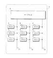
- FIG. 4 is a schematic diagram showing a configuration example of the first routing map 62b.
- FIG. 5 is a schematic diagram illustrating a configuration example of the second routing map 62c.
- the CAN ID (CAN-ID) attached to the message
- the ECU transmission ECU
- the ECU that should receive the message (reception ECU)
- the message Information such as whether or not a message relay is necessary (relay necessity), message relay source communication line (relay source communication line), message relay destination communication line (relay destination communication line), etc.
- the examples shown in FIGS. 4 and 5 are based on the network configuration shown in FIG. 2, and the plurality of ECUs 2 connected to the communication lines 11 to 13 are distinguished by reference numerals 2A to 2F shown in FIG.
- the message with 0x012 (hexadecimal number) attached to the CAN-ID is a message that needs to be transmitted by the ECU 2A connected to the communication line 11 and received by the ECU 2B connected to the communication line 11.
- the message with 0x013 added to the CAN-ID is a message that needs to be transmitted by the ECU 2A connected to the communication line 11 and received by the ECU 2C connected to the communication line 12.
- the message with 0x015 added to the CAN-ID is a message that needs to be transmitted by the ECU 2A connected to the communication line 11 and received by the ECU 2E connected to the communication line 13.
- the gateway 5 When the communication lines 11 to 13 are in the connected state, the gateway 5 performs a relay process using the first routing map 62b shown in FIG.
- the gateway 5 in the connected state, all the communication lines 11 to 13 are electrically connected, and the gateway 5 does not need to relay the message. Therefore, in the first routing map 62b, “no” is set as the necessity of relay for all messages of CAN-ID.
- the first routing map 62b may not be stored in the storage unit 62. .
- the gateway 5 When the communication lines 11 to 13 are in the separated state, the gateway 5 performs a relay process using the second routing map 62c shown in FIG.
- the second routing map 62c both the transmission source ECU 2A and the reception destination ECU 2B are connected to the communication line 11 for the message with CAN-ID 0x12, and can be directly transmitted and received between the ECUs 2A and 2B. Therefore, “No” is set in the necessity of relay, and the gateway 5 does not relay this message.
- the transmission source ECU 2A is connected to the communication line 11
- the reception destination ECU 2C is connected to the communication line 12. The gateway 5 relays this message from the communication line 11 to the communication line 12.
- the message with CAN-ID 0x15 is set to “necessary” for the necessity of relay because the ECU 2A of the transmission source is connected to the communication line 11 and the ECU 2E of the reception destination is connected to the communication line 13.
- the gateway 5 relays this message from the communication line 11 to the communication line 13.
- the gateway 5 switches the routing map used for the message relay process in accordance with the switching of the connection state and the separation state of the communication lines 11 to 13 by the bus switching unit 55, whereby the network configuration of the communication lines 11 to 13 is achieved. It is possible to appropriately carry out message relay processing in response to changes in In the case of this example, when the communication lines 11 to 13 are in the connected state, the message relay is not required. However, the present invention is not limited to this. For example, in the connected state, only the communication lines 11 and 12 are connected. The communication line 13 may be connected and the communication line 13 may not be connected. In such a case, the first routing map 62b includes the ECU 2 connected to the communication line 11 or 12 and the ECU 2 connected to the communication line 13. An appropriate value is set to relay the message.
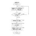
- FIG. 6 is a flowchart showing a procedure of processing performed by the gateway 5 when the communication lines 11 to 13 are connected.
- the communication state detection unit 61b of the processing unit 61 of the control unit 50 of the gateway 5 measures the amount of messages received by the communication unit 51 at a predetermined time (step S1).
- the bus switching control unit 61c of the processing unit 61 determines whether or not the message amount measured in step S1 exceeds a predetermined amount (step S2).
- the processing unit 61 returns the processing to step S1, and repeats measurement of the message amount and determination with the predetermined amount.
- the bus switching control unit 61c switches the switches SW1 to SW4 by outputting a switching signal to the bus switching unit 55, and the communication lines 11 to 13 is switched to the separated state (step S3). Further, the relay rule switching unit 61d of the processing unit 61 switches the routing map used for the relay process from the first routing map 62b to the second routing map 62c (step S4). In addition, the processing unit 61 starts the communication units 52 and 53 connected to the communication lines 12 and 13 by switching the bus switching unit 55 from the power saving state and shifts to the normal operation state (step S5). Terminate the process.
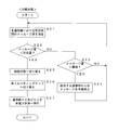
- FIG. 7 is a flowchart showing a procedure of processing performed by the gateway 5 when the communication lines 11 to 13 are in the separated state.
- the communication state detection unit 61b of the processing unit 61 of the control unit 50 of the gateway 5 measures the amount of messages received by each of the communication units 51 to 53 in a predetermined time (step S21).
- the bus switching control unit 61c of the processing unit 61 determines whether or not the measured message amount of each of the communication units 51 to 53 measured in step S21 is less than a predetermined amount (step S22).
- the relay prohibition unit 61e of the processing unit 61 sets the message amount measured in step S21 to a threshold (> predetermined amount). It is further determined whether or not it exceeds (step S23). When the message amount exceeds the threshold (S23: YES), the relay prohibition unit 61e prohibits relaying of the message received by the communication units 51 to 53 whose message amount exceeds the threshold (step S24), and proceeds to step S21. Return processing. If the message amount does not exceed the threshold (S23: NO), the relay prohibition unit 61e returns the process to step S21.
- the bus switching control unit 61c switches the switches SW1 to SW4 by outputting a switching signal to the bus switching unit 55.
- the communication lines 11 to 13 are switched to the connected state (step S25).
- the relay rule switching unit 61d of the processing unit 61 switches the routing map used for the relay process from the second routing map 62c to the first routing map 62b (step S26).
- the processing unit 61 shifts the communication units 52 and 53 disconnected from the communication lines 12 and 13 by switching the bus switching unit 55 from the normal operation state to the power saving state (step S27), and performs processing in the separated state. finish.
- the switch of the bus switching unit 55 is switched to a connection state in which the three communication lines 11 to 13 connected to the gateway 5 are directly connected or in a separated state. Switch using SW1 to SW4.
- the ECU 2 connected to the communication lines 11 to 13 can directly transmit / receive messages to / from other ECUs 2 without relaying messages by the gateway 5. It becomes.
- the bus switching unit 55 switches to the connected state, the communication units 52 and 53 that transmit and receive messages to and from the communication lines 11 to 13 do not need to operate, and shift to the power saving state to reduce power consumption. It becomes possible to reduce.
- the communication line 11 to 13 can be separated by the bus switching unit 55, so that the communication load can be distributed and reduced. it can.
- the connection / separation of the communication lines 11 to 13 changes the network configuration in the communication system. Therefore, the gateway 5 switches the message relay rule according to the network configuration, that is, according to the switching state of the bus switching unit 55. Specifically, the gateway 5 stores a plurality of routing maps in which the message and the relay destination of the message are associated with each other in the storage unit 62, and stores the first routing map stored in the storage unit 62 according to the switching state of the bus switching unit 55. A message is relayed by selecting and using either the first routing map 62b or the second routing map 62c.
- the gateway 5 detects the communication state of the communication lines 11 to 13, for example, the message amount in a predetermined time, and switches the switches SW1 to SW4 of the bus switching unit 55 according to the detected communication state. At this time, the gateway 5 detects a common communication state for the plurality of communication lines 11 to 13 in the connected state, and individually detects a communication state for the communication lines 11 to 13 in the separated state. For example, when the message amount is less than a predetermined amount, the gateway 5 switches the bus switching unit 55 to place the plurality of communication lines 11 to 13 in the connected state, and sets the separated state when the message amount exceeds the predetermined amount.
- the communication lines 11 to 13 are connected to reduce the power consumption of the communication ICs constituting the communication units 52 and 53, and when the message amount is large, the plurality of communication lines 11 to 13 are connected.
- the communication load can be reduced by distributing the communication lines 11 to 13 in a separated state.
- the gateway 5 detects the message amount for each of the separated communication lines 11 to 13 after switching the switches SW1 to SW4 of the bus switching unit 55 to the separated state when the message amount exceeds a predetermined amount.
- the gateway 5 relays the message received on the communication lines 11 to 13 to the other communication lines 11 to 13. Is prohibited.
- an unauthorized communication device connected to any one of the communication lines 11 to 13 performs an attack in which a large number of messages are transmitted, the communication lines 11 to 13 are disconnected from the communication system and are transferred to the entire system. Can be reduced.
- the gateway 5 is configured to switch all three communication lines 11 to 13 by connecting the switches SW1 to SW4 of the bus switching unit 55.
- the present invention is not limited to this. Absent.
- the gateway 5 has a configuration in which the switches SW1 and SW2 and the switches SW3 and SW4 of the bus switching unit 55 can be switched independently, and the communication lines 11 and 12 are connected and the communication line 13 is separated, or the communication It is good also as a structure which can be switched to the state etc. which connected the lines 11 and 13 and isolate
- the present invention is not limited to this, and a configuration in which two or four or more communication lines are connected may be used.
- the configuration of the routing map and the set values shown in FIGS. 4 and 5 are examples, and the present invention is not limited to this.
- the communication system according to the present embodiment is mounted on the vehicle 1, it is not limited to this.
- the communication system may be mounted on a mobile body such as a ship or an aircraft other than the vehicle 1, or may be installed in a home, factory, school, office, or the like other than the mobile body.
- the gateway 5 is configured to switch the switches SW1 to SW4 of the bus switching unit 55 according to the message amount of the communication lines 11 to 13 for a predetermined time.
- the configuration is not limited to this, and the configuration is performed for switching under other conditions. It is good.
- the gateway 5 can be configured to switch the switches SW1 to SW4 of the bus switching unit 55 in accordance with the on / off state of the IG (ignition) switch of the vehicle 1. In this configuration, for example, the gateway 5 places the communication lines 11 to 13 in the connected state when the IG switch is off, and places the communication lines 11 to 13 in the separated state when the IG switch is on.
- the gateway 5 can shift the communication units 52 and 53 to the power saving state by setting the communication lines 11 to 13 in the connected state in the state where the IG switch is turned off and the engine of the vehicle 1 is stopped. Consumption of power stored in the battery can be reduced. Further, the gateway 5 can distribute the communication load by setting the communication lines 11 to 13 in the separated state in a state where the IG switch is turned on and the ECU 2 mounted on the vehicle 1 is likely to operate to increase the amount of messages. it can.
- the processing unit 61 is not configured as a CPU that executes the program and performs processing, and the processing is hardware-like.
- the relay program 62a does not need to be stored in the storage unit 62.
- the processing unit 61 reads and executes the relay program 62a stored in the storage unit 62
- the relay program 62a is stored in the storage unit 62 before being mounted on the circuit board in the manufacturing process of the gateway 5, for example. On the other hand, it may be written directly, or may be written using the communication function of the gateway 5.
- the relay program 62a is provided by being recorded on a recording medium 99 such as a memory card or an optical disk, and is relayed from the recording medium 99 by a device such as a memory card slot or an optical disk drive provided in the gateway 5 or the vehicle 1. May be read and written to the storage unit 62.
- a recording medium 99 such as a memory card or an optical disk
- a device such as a memory card slot or an optical disk drive provided in the gateway 5 or the vehicle 1. May be read and written to the storage unit 62.
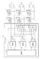
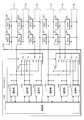
- FIG. 8 is a schematic diagram illustrating a configuration of the gateway 105 according to the modification.
- Six communication lines 111 to 116 are connected to the gateway 105 according to the modification.
- ECUs 2A and 2B are connected to the communication line 111
- ECUs 2C and 2D are connected to the communication line 112
- ECUs 2E and 2F are connected to the communication line 113.
- ECUs 2G and 2H are connected to the communication line 114
- ECUs 2I and 2J are connected to the communication line 115
- ECUs 2K and 2L are connected to the communication line 116.
- the gateway 105 according to the modification includes a control unit 150, six communication units 151 to 156, and two bus switching units 157 and 158.
- the configuration of the gateway 105 according to the modification corresponds to a configuration including two sets of switching control configurations by the communication units 51 to 53 and the bus switching unit 55 included in the gateway 5 illustrated in FIG. That is, the gateway 105 according to the modified example switches the connection state / separation state of the communication lines 111 to 113 by the communication units 151 to 153 and the bus switching unit 157, and the communication line 114 to the communication units 154 to 156 and the bus switching unit 158. The connection state / separation state of .about.116 is switched.
- the control unit 150 of the gateway 105 detects the message amount of the communication lines 111 to 113 in the communication units 151 to 153, and switches the switch of the bus switching unit 157 according to the detection result. Control is performed to switch 111 to 113 to the connected state or the separated state. In addition, the control unit 150 detects the message amount of the communication lines 114 to 156 in the communication units 154 to 156, and switches the switch of the bus switching unit 158 according to the detection result, thereby connecting the communication lines 114 to 116 to the connected state. Alternatively, control to switch to the separated state is performed.
- control unit 150 can independently control switching of the connection state / separation state of the communication lines 111 to 113 and switching of the connection state / separation state of the communication lines 114 to 116.
- the message relay process performed by the control unit 150 can relay a message received on any of the six communication lines 111 to 116 to any of the six communication lines 111 to 116. Therefore, the control unit 150 of the gateway 105 according to the modified example displays four routing maps according to the combination of the connection state / separation state of the communication lines 111 to 113 and the connection state / separation state of the communication lines 114 to 116. It is stored in the storage unit.
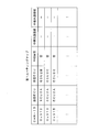
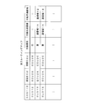
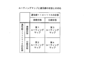
- FIG. 9 is a table showing the correspondence between the routing map stored in the gateway 105 according to the modification and the states of the communication lines 111 to 116.
- the gateway 105 according to the modified example stores four routing maps, a first routing map to a fourth routing map.
- the gateway 105 performs message relay processing using the first routing map.
- the gateway 105 performs message relay processing using the second routing map.
- the gateway 105 performs message relay processing using the third routing map.
- the gateway 105 performs message relay processing using the fourth routing map.
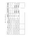
- FIG. 10 is a schematic diagram illustrating a configuration example of the first routing map according to the modification.
- the gateway 105 according to the modified example performs message relay processing using the illustrated first routing map when the communication lines 111 to 113 are in a connected state and the communication lines 114 to 116 are in a connected state. Since the communication lines 111 to 113 are connected and the communication lines 114 to 116 are connected, the communication system in this state is substantially equivalent to a state where the ECUs 2A to 2L are connected to the two communication lines.
- a message transmitted by the ECU 2A connected to one communication line 111 is directly received by the ECUs 2B to 2F without being relayed by the gateway 105, or is relayed by the gateway 105 and connected to the other communication line 114. Is received by the ECUs 2G to 2L.
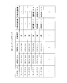
- FIG. 11 is a schematic diagram showing a configuration example of the second routing map according to the modification.
- the gateway 105 according to the modification performs message relay processing using the illustrated second routing map when the communication lines 111 to 113 are in the separated state and the communication lines 114 to 116 are in the connected state. Since the communication lines 111 to 113 are in the separated state and the communication lines 114 to 116 are in the connected state, the communication system in this state is substantially equivalent to a state in which the ECUs 2A to 2L are connected to the four communication lines.
- the message transmitted by the ECU 2A connected to the communication line 111 is directly received by the ECU 2B connected to the communication line 11 without being relayed by the gateway 105, or is relayed by the gateway 105 to the communication line 112 or 113. It is received by the connected ECUs 2C to 2F or received by the ECUs 2G to 2L relayed by the gateway 105 and connected to the connected communication line 114.
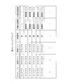
- FIG. 12 is a schematic diagram illustrating a configuration example of a third routing map according to the modification.
- the gateway 105 according to the modification performs message relay processing using the illustrated third routing map when the communication lines 111 to 113 are in a connected state and the communication lines 114 to 116 are in a separated state. Since the communication lines 111 to 113 are connected and the communication lines 114 to 116 are separated, the communication system in this state is substantially equivalent to a state where the ECUs 2A to 2L are connected to the four communication lines.
- the message transmitted by the ECU 2A connected to the communication line 111 is directly received by the ECUs 2B to 2F without being relayed by the gateway 105, or is relayed by the gateway 105 to any one of the communication lines 114 to 116. It is received by the connected ECUs 2G to 2L.
- FIG. 13 is a schematic diagram illustrating a configuration example of a fourth routing map according to the modification.
- the gateway 105 When the communication lines 111 to 113 are in the separated state and the communication lines 114 to 116 are in the separated state, the gateway 105 according to the modified example performs message relay processing using the illustrated fourth routing map. Since all the communication lines 111 to 116 are in the separated state, the gateway 105 relays messages between the six communication lines 111 to 116 in the communication system in this state.
- the gateway 105 is configured to switch the connection state / separation state by dividing the six communication lines 111 to 116 into two sets of three.
- the number of communication lines, the number of groupings, and the like for switching the connection state / separation state by the gateway are not limited to those shown in the present modification, and various configurations can be employed.
Landscapes
- Engineering & Computer Science (AREA)
- Computer Networks & Wireless Communication (AREA)
- Signal Processing (AREA)
- Small-Scale Networks (AREA)
Priority Applications (3)
| Application Number | Priority Date | Filing Date | Title |
|---|---|---|---|
| DE112018002875.5T DE112018002875T5 (de) | 2017-06-06 | 2018-05-23 | Weiterleitungsvorrichtung, Weiterleitungsverfahren und Weiterleitungsprogramm |
| CN201880033094.9A CN110637445A (zh) | 2017-06-06 | 2018-05-23 | 中继装置、中继方法及中继程序 |
| US16/614,820 US20200204397A1 (en) | 2017-06-06 | 2018-05-23 | Relay apparatus, relay method and relay program |
Applications Claiming Priority (2)
| Application Number | Priority Date | Filing Date | Title |
|---|---|---|---|
| JP2017-111878 | 2017-06-06 | ||
| JP2017111878A JP2018207343A (ja) | 2017-06-06 | 2017-06-06 | 中継装置、中継方法及び中継プログラム |
Publications (1)
| Publication Number | Publication Date |
|---|---|
| WO2018225513A1 true WO2018225513A1 (ja) | 2018-12-13 |
Family
ID=64566292
Family Applications (1)
| Application Number | Title | Priority Date | Filing Date |
|---|---|---|---|
| PCT/JP2018/019822 Ceased WO2018225513A1 (ja) | 2017-06-06 | 2018-05-23 | 中継装置、中継方法及び中継プログラム |
Country Status (5)
| Country | Link |
|---|---|
| US (1) | US20200204397A1 (cg-RX-API-DMAC7.html) |
| JP (1) | JP2018207343A (cg-RX-API-DMAC7.html) |
| CN (1) | CN110637445A (cg-RX-API-DMAC7.html) |
| DE (1) | DE112018002875T5 (cg-RX-API-DMAC7.html) |
| WO (1) | WO2018225513A1 (cg-RX-API-DMAC7.html) |
Families Citing this family (5)
| Publication number | Priority date | Publication date | Assignee | Title |
|---|---|---|---|---|
| WO2022163386A1 (ja) * | 2021-01-27 | 2022-08-04 | 株式会社オートネットワーク技術研究所 | 車載装置、及び中継方法 |
| JP7632123B2 (ja) * | 2021-06-30 | 2025-02-19 | 株式会社オートネットワーク技術研究所 | 中継装置、中継システム、中継方法及びコンピュータプログラム |
| JP7616097B2 (ja) * | 2022-01-17 | 2025-01-17 | 株式会社オートネットワーク技術研究所 | 車載システム、管理装置及び管理方法 |
| JP2023178626A (ja) * | 2022-06-06 | 2023-12-18 | 矢崎総業株式会社 | 接続切替装置および通信システム |
| KR20250005730A (ko) * | 2023-07-03 | 2025-01-10 | 삼성에스디아이 주식회사 | Can 통신 장치 및 방법 |
Citations (2)
| Publication number | Priority date | Publication date | Assignee | Title |
|---|---|---|---|---|
| JP2004350137A (ja) * | 2003-05-23 | 2004-12-09 | Denso Corp | 車両用通信システム |
| JP2007251722A (ja) * | 2006-03-17 | 2007-09-27 | Fujitsu Ten Ltd | 通信装置、車載システム、データ保存方法及びプログラム |
Family Cites Families (10)
| Publication number | Priority date | Publication date | Assignee | Title |
|---|---|---|---|---|
| JP3770058B2 (ja) * | 2000-06-16 | 2006-04-26 | 株式会社日立製作所 | フレーム分配方法およびその機能を有する情報処理装置 |
| JP4418302B2 (ja) * | 2004-05-31 | 2010-02-17 | 独立行政法人科学技術振興機構 | 中継装置、パケットフィルタリング方法及びパケットフィルタリングプログラム |
| JP2007166302A (ja) * | 2005-12-14 | 2007-06-28 | Denso Corp | 車載ネットワーク中継装置 |
| CN101064911B (zh) * | 2006-04-28 | 2012-08-22 | 上海贝尔阿尔卡特股份有限公司 | 无线接入系统的切换控制方法、中继站和基站 |
| CN101286781B (zh) * | 2007-04-13 | 2013-02-27 | 中兴通讯股份有限公司 | 一种无线中继站连接关系终止的方法 |
| CN101534153A (zh) * | 2008-03-12 | 2009-09-16 | 华为技术有限公司 | 一种中继器管理的方法、装置和系统 |
| JP6201962B2 (ja) * | 2014-11-06 | 2017-09-27 | トヨタ自動車株式会社 | 車載通信システム |
| CN105760107B (zh) * | 2014-12-15 | 2019-02-05 | 联想(北京)有限公司 | 一种存储设备、电子设备和信息处理方法 |
| DE112016005087B4 (de) * | 2015-11-05 | 2024-08-29 | Hitachi Astemo, Ltd. | Relaisvorrichtung, elektronische Steuervorrichtung und fahrzeugmontiertes Netzsystem |
| CN105353604B (zh) * | 2015-12-01 | 2018-01-23 | 清华大学 | 一种双机冷热备份自主切换的控制与信息处理系统及方法 |
-
2017
- 2017-06-06 JP JP2017111878A patent/JP2018207343A/ja not_active Ceased
-
2018
- 2018-05-23 DE DE112018002875.5T patent/DE112018002875T5/de not_active Withdrawn
- 2018-05-23 CN CN201880033094.9A patent/CN110637445A/zh active Pending
- 2018-05-23 US US16/614,820 patent/US20200204397A1/en not_active Abandoned
- 2018-05-23 WO PCT/JP2018/019822 patent/WO2018225513A1/ja not_active Ceased
Patent Citations (2)
| Publication number | Priority date | Publication date | Assignee | Title |
|---|---|---|---|---|
| JP2004350137A (ja) * | 2003-05-23 | 2004-12-09 | Denso Corp | 車両用通信システム |
| JP2007251722A (ja) * | 2006-03-17 | 2007-09-27 | Fujitsu Ten Ltd | 通信装置、車載システム、データ保存方法及びプログラム |
Also Published As
| Publication number | Publication date |
|---|---|
| US20200204397A1 (en) | 2020-06-25 |
| CN110637445A (zh) | 2019-12-31 |
| JP2018207343A (ja) | 2018-12-27 |
| DE112018002875T5 (de) | 2020-02-27 |
Similar Documents
| Publication | Publication Date | Title |
|---|---|---|
| WO2018225513A1 (ja) | 中継装置、中継方法及び中継プログラム | |
| JP6967664B2 (ja) | ゲートウェイ装置 | |
| US11063968B2 (en) | Communication system, communication device, relay device, communication integrated circuit (IC), control IC, and communication method | |
| US11936500B2 (en) | In-vehicle network system, relay device, and method of controlling in-vehicle network system | |
| JP7063010B2 (ja) | 中継装置、通信システムおよび中継制御装置 | |
| JP2008278403A (ja) | 監視装置及びネットワークシステムの監視方法 | |
| US8077733B2 (en) | Vehicle gateway device, a communication data control method and computer program product therefor | |
| JP2020039077A (ja) | 車両用通信装置 | |
| JP2007336267A (ja) | 車載通信システム | |
| JP2008114806A (ja) | 車載装置中継システム、車載装置中継方法及び中継装置 | |
| JP7415364B2 (ja) | 車載中継装置、コンピュータプログラム及び故障判定方法 | |
| JP4645599B2 (ja) | データ中継装置 | |
| WO2021177019A1 (ja) | 車載中継装置、及びコンピュータプログラム | |
| JP4786330B2 (ja) | 車載lanシステム、電子制御ユニットおよび中継接続ユニット | |
| JP7205439B2 (ja) | 電子制御装置 | |
| JP2007228232A (ja) | 車載lanシステム、電子制御ユニットおよび中継接続ユニット | |
| JP2019186644A (ja) | 車載通信システム、車載通信装置、通信プログラム及び通信方法 | |
| JP2008278246A (ja) | 通信システム、通信装置及び通信方法 | |
| JP2015048026A (ja) | 電子制御装置 | |
| JP4839140B2 (ja) | 中継接続ユニット | |
| JP6950516B2 (ja) | 中継装置 | |
| EP3709167A1 (en) | Vehicle communication system | |
| US12143241B2 (en) | Vehicle-mounted apparatus and a method for relaying | |
| JP7700705B2 (ja) | 給電制御装置、給電制御システム及び給電制御方法 | |
| JP5120783B2 (ja) | 中継装置、当該装置で実行される中継方法、及び当該装置からなる中継システム |
Legal Events
| Date | Code | Title | Description |
|---|---|---|---|
| 121 | Ep: the epo has been informed by wipo that ep was designated in this application |
Ref document number: 18813047 Country of ref document: EP Kind code of ref document: A1 |
|
| 122 | Ep: pct application non-entry in european phase |
Ref document number: 18813047 Country of ref document: EP Kind code of ref document: A1 |