WO2018225513A1 - Relay device, relay method and relay program - Google Patents
Relay device, relay method and relay program Download PDFInfo
- Publication number
- WO2018225513A1 WO2018225513A1 PCT/JP2018/019822 JP2018019822W WO2018225513A1 WO 2018225513 A1 WO2018225513 A1 WO 2018225513A1 JP 2018019822 W JP2018019822 W JP 2018019822W WO 2018225513 A1 WO2018225513 A1 WO 2018225513A1
- Authority
- WO
- WIPO (PCT)
- Prior art keywords
- communication
- relay
- state
- message
- communication lines
- Prior art date
Links
Images

Classifications
-
- H—ELECTRICITY
- H04—ELECTRIC COMMUNICATION TECHNIQUE
- H04L—TRANSMISSION OF DIGITAL INFORMATION, e.g. TELEGRAPHIC COMMUNICATION
- H04L12/00—Data switching networks
- H04L12/28—Data switching networks characterised by path configuration, e.g. LAN [Local Area Networks] or WAN [Wide Area Networks]
- H04L12/40—Bus networks
- H04L12/40169—Flexible bus arrangements
- H04L12/40176—Flexible bus arrangements involving redundancy
- H04L12/40182—Flexible bus arrangements involving redundancy by using a plurality of communication lines
-
- H—ELECTRICITY
- H04—ELECTRIC COMMUNICATION TECHNIQUE
- H04L—TRANSMISSION OF DIGITAL INFORMATION, e.g. TELEGRAPHIC COMMUNICATION
- H04L12/00—Data switching networks
- H04L12/28—Data switching networks characterised by path configuration, e.g. LAN [Local Area Networks] or WAN [Wide Area Networks]
- H04L12/40—Bus networks
- H04L12/40006—Architecture of a communication node
- H04L12/40013—Details regarding a bus controller
-
- H—ELECTRICITY
- H04—ELECTRIC COMMUNICATION TECHNIQUE
- H04L—TRANSMISSION OF DIGITAL INFORMATION, e.g. TELEGRAPHIC COMMUNICATION
- H04L12/00—Data switching networks
- H04L12/28—Data switching networks characterised by path configuration, e.g. LAN [Local Area Networks] or WAN [Wide Area Networks]
- H04L12/46—Interconnection of networks
-
- H—ELECTRICITY
- H04—ELECTRIC COMMUNICATION TECHNIQUE
- H04L—TRANSMISSION OF DIGITAL INFORMATION, e.g. TELEGRAPHIC COMMUNICATION
- H04L12/00—Data switching networks
- H04L12/66—Arrangements for connecting between networks having differing types of switching systems, e.g. gateways
-
- H—ELECTRICITY
- H04—ELECTRIC COMMUNICATION TECHNIQUE
- H04L—TRANSMISSION OF DIGITAL INFORMATION, e.g. TELEGRAPHIC COMMUNICATION
- H04L47/00—Traffic control in data switching networks
- H04L47/10—Flow control; Congestion control
- H04L47/29—Flow control; Congestion control using a combination of thresholds
-
- H—ELECTRICITY
- H04—ELECTRIC COMMUNICATION TECHNIQUE
- H04L—TRANSMISSION OF DIGITAL INFORMATION, e.g. TELEGRAPHIC COMMUNICATION
- H04L12/00—Data switching networks
- H04L12/28—Data switching networks characterised by path configuration, e.g. LAN [Local Area Networks] or WAN [Wide Area Networks]
- H04L12/40—Bus networks
- H04L2012/40208—Bus networks characterized by the use of a particular bus standard
- H04L2012/40215—Controller Area Network CAN
-
- H—ELECTRICITY
- H04—ELECTRIC COMMUNICATION TECHNIQUE
- H04L—TRANSMISSION OF DIGITAL INFORMATION, e.g. TELEGRAPHIC COMMUNICATION
- H04L12/00—Data switching networks
- H04L12/28—Data switching networks characterised by path configuration, e.g. LAN [Local Area Networks] or WAN [Wide Area Networks]
- H04L12/40—Bus networks
- H04L2012/40267—Bus for use in transportation systems
- H04L2012/40273—Bus for use in transportation systems the transportation system being a vehicle
-
- H—ELECTRICITY
- H04—ELECTRIC COMMUNICATION TECHNIQUE
- H04L—TRANSMISSION OF DIGITAL INFORMATION, e.g. TELEGRAPHIC COMMUNICATION
- H04L47/00—Traffic control in data switching networks
- H04L47/10—Flow control; Congestion control
- H04L47/12—Avoiding congestion; Recovering from congestion
- H04L47/125—Avoiding congestion; Recovering from congestion by balancing the load, e.g. traffic engineering
-
- H—ELECTRICITY
- H04—ELECTRIC COMMUNICATION TECHNIQUE
- H04L—TRANSMISSION OF DIGITAL INFORMATION, e.g. TELEGRAPHIC COMMUNICATION
- H04L47/00—Traffic control in data switching networks
- H04L47/10—Flow control; Congestion control
- H04L47/13—Flow control; Congestion control in a LAN segment, e.g. ring or bus
-
- H—ELECTRICITY
- H04—ELECTRIC COMMUNICATION TECHNIQUE
- H04L—TRANSMISSION OF DIGITAL INFORMATION, e.g. TELEGRAPHIC COMMUNICATION
- H04L49/00—Packet switching elements
- H04L49/50—Overload detection or protection within a single switching element
- H04L49/501—Overload detection
-
- H—ELECTRICITY
- H04—ELECTRIC COMMUNICATION TECHNIQUE
- H04L—TRANSMISSION OF DIGITAL INFORMATION, e.g. TELEGRAPHIC COMMUNICATION
- H04L49/00—Packet switching elements
- H04L49/50—Overload detection or protection within a single switching element
- H04L49/501—Overload detection
- H04L49/503—Policing
Definitions
- the present invention relates to a relay apparatus, a relay method, and a relay program that perform processing for relaying message transmission / reception between a plurality of communication lines.
- a gateway node connected to a plurality of CAN (Controller Area Network) buses is intended to suppress communication delay of important frames, occurrence of reception omission and transmission delay of low priority ID.
- a network system has been proposed.
- the gateway node monitors the load state of the CAN bus and adjusts the bus load according to the bus load state.
- the bus load is adjusted by reducing the relay processing by the gateway node, reducing the data length of the relay frame, increasing the frame transmission cycle by another node, or reducing the data length of the transmission frame.
- the CAN controller calculates the bus load factor of the network, determines the level of the network load based on the bus load factor, and transmits the communication message itself based on the determination result indicating that the load is high.
- Communication devices to be regulated have been proposed.
- a relay device to which a plurality of communication lines are connected is provided with a communication IC (Integrated Circuit) that transmits and receives messages for each communication line.
- a communication IC Integrated Circuit
- an unauthorized communication device is connected to a communication line, and the unauthorized communication device transmits a large number of messages to the communication line, thereby preventing a malicious attack such as preventing transmission and reception of messages by a legitimate communication device.
- a malicious attack such as preventing transmission and reception of messages by a legitimate communication device.
- the communication system is affected.
- the amount of communication is reduced according to the bus load, but it is difficult to cope with an attack in which an unauthorized communication device transmits a large number of messages.
- the present invention has been made in view of such circumstances, and an object of the present invention is to provide a relay device and a relay method capable of suppressing an increase in power consumption accompanying the operation of a communication IC or the like. It is in. Another object of the present invention is to provide a relay device, a relay method, and a relay program that can reduce the influence on the entire system due to an attack in which an unauthorized communication device transmits a large number of messages.
- the relay device is a relay device comprising a relay unit to which a plurality of communication lines are connected and a message received on one communication line is transmitted from another communication line to relay the message.
- a switch that switches to a connection state in which at least two communication lines included in the communication line are connected or a separation state in which the communication lines are individually separated, and the relay rule of the message by the relay unit is switched according to the switching state of the switch And a relay rule switching unit.
- the relay device includes a communication state detection unit that detects a communication state of the communication line, and switches the switch according to the communication state detected by the communication state detection unit.
- the communication state detection unit detects the amount of messages transmitted / received via the communication line, and the switch is connected when the amount of the messages is less than a predetermined amount. When the amount of the message exceeds a predetermined amount, the switch is switched to a separated state.
- the relay unit may receive a message received on a communication line in which the amount of messages detected by the communication state detection unit exceeds a second predetermined amount after the switch is switched to the separated state.
- a relay prohibiting unit that prohibits relaying to the communication line is provided.
- the relay device includes a storage unit that stores a plurality of pieces of relay information in which a message and a relay destination of the message are associated with each other, and any one from the storage unit according to a switching state of the switch.
- the relay rule of the message is switched by reading one relay information.
- a relay apparatus that relays the message by transmitting a message received on one communication line from another communication line includes the plurality of communication lines. It is switched to a connection state in which at least two communication lines included in the line are connected or to a separation state in which the communication lines are individually separated, and a message relay rule is switched according to the switching state.
- the relay program according to the present invention includes a relay unit that connects a plurality of communication lines, relays the message by transmitting a message received on one communication line from another communication line, and the plurality of the plurality of communication lines.
- a relay apparatus having a switch that switches to a connection state that connects at least two communication lines included in the communication line or a separation state that separates the communication lines individually, the switch is switched according to the communication state of the communication line, The relay rule of the message by the relay unit is switched according to the switching state of the switch.
- At least two communication lines included in a plurality of communication lines connected to the relay apparatus are switched using a switch to a connection state in which they are directly connected or a separation state in which they are individually separated.
- a directly connected communication line it is possible to send and receive messages without relaying messages by a relay device.
- the switch is switched to the connected state, the communication IC that transmits and receives messages to and from the communication line does not need to operate, and shifts to a low power consumption state such as a sleep state or a standby state. Can be reduced.
- the communication load can be distributed and reduced by individually setting the communication line in the separated state by the switch.
- the relay apparatus switches the message relay rule according to the network configuration, that is, according to the switch switching state.
- the relay apparatus stores a plurality of pieces of information such as a so-called routing map or a routing table in which a message is associated with a relay destination that relays the message, and any one of them according to the switching state of the switch.
- Message relay rules can be switched by relaying messages using relay information.
- the communication state of a communication line is detected and a switch is switched according to the detected communication state.
- the relay device detects a common communication state for a plurality of communication lines in a connected state, and individually detects a communication state for a communication line in a separated state.
- the communication state to be detected can be, for example, the amount of messages transmitted / received in a predetermined time. For example, when the message amount is less than a predetermined amount, the relay device switches the switch to connect the plurality of communication lines, and when the message amount exceeds the predetermined amount, the relay device is set to the separated state.
- the amount of messages is small, the power consumption of the communication IC is reduced by connecting multiple communication lines, and when the amount of messages is large, the communication load is distributed by separating the multiple communication lines. Can be reduced.
- the relay device detects the communication state of each separated communication line after switching the switch to the separated state because the message amount exceeds a predetermined amount.
- the relay device prohibits relaying a message received on this communication line to another communication line.
- the second predetermined amount may be the same value as or a different value from the predetermined amount serving as a switch switching determination criterion.
- an increase in power consumption associated with the operation of the communication IC or the like can be suppressed by providing a switch for switching a plurality of communication lines to a connected state. Further, in the case of the present invention, when the message amount of the communication line in the separated state exceeds the second predetermined amount, the relay of the message from this communication line is prohibited so that a large number of unauthorized communication devices can be obtained. It is possible to reduce the influence on the entire system by the attack of sending a message.
- FIG. 1 is a schematic diagram showing a configuration of a communication system according to the present embodiment.
- the communication system according to the present embodiment has a configuration in which a plurality of ECUs 2 mounted on a vehicle 1 indicated by broken lines transmit and receive messages via a plurality of communication lines 11 to 13 and a gateway 5 mounted on the vehicle 1. is there.
- the vehicle 1 is provided with a plurality of bus-type communication lines 11 to 13 at appropriate positions, and the communication lines 11 to 13 are connected to the gateway 5.
- One or a plurality of ECUs (Electronic Control Units) 2 are connected to each of the communication lines 11 to 13.
- the gateway 5 relays message transmission / reception between ECUs 2 connected to different communication lines 11 to 13 by relaying messages between the communication lines 11 to 13.
- the ECU 2 includes, for example, an ECU that controls the operation of the engine of the vehicle 1, an ECU that controls the locking / unlocking of the door, an ECU that controls the turning on / off of the light, an ECU that controls the operation of the airbag, and an ABS (Antilock Various ECUs such as an ECU for controlling the operation of the Brake System may be included.
- Each ECU 2 is connected to any one of the communication lines 11 to 13 arranged in the vehicle 1, and can send and receive messages to and from other ECUs 2 through the communication lines 11 to 13 and the gateway 5.
- the gateway 5 is connected to a plurality of communication lines 11 to 13 constituting the in-vehicle network of the vehicle 1 and performs a process of relaying message transmission / reception between the communication lines 11 to 13.
- three communication lines 11 to 13 are connected to the gateway 5, and three ECUs 2 are connected to each of the communication lines 11 to 13, respectively.
- the number of communication lines 11 to 13 connected to the gateway 5 and the number of ECUs 2 connected to the communication lines 11 to 13 are merely examples, and are not limited thereto.
- the gateway 5 can relay the message by transmitting the message received on any one of the communication lines 11 to 13 to the other communication lines 11 to 13.
- the ECU 2 and the gateway 5 transmit and receive messages in accordance with a CAN (Controller Area Network) communication protocol.
- the ECU 2 and the gateway 5 may be configured to transmit and receive messages according to a communication protocol other than CAN, for example, a communication protocol such as FlexRay or LIN (Local Interconnect Network).
- the ECU 2 and the gateway 5 may be configured to transmit and receive messages via at least a bus-type communication line.
- FIG. 2 is a schematic diagram showing the configuration of the gateway 5.
- the gateway 5 includes a control unit 50, communication units 51 to 53, a bus switching unit 55, and the like.
- CAN is adopted as a communication protocol
- communication lines 11 to 13 (so-called CAN bus) in the CAN communication protocol are two-wire.
- the communication line 11 is comprised by the two of the 1st communication line 11H and the 2nd communication line 11L
- the communication line 12 is comprised by the two of the 1st communication line 12H and the 2nd communication line 12L.
- the communication line 13 is composed of two lines, the first communication line 13H and the second communication line 13L.
- ECU 2 connected to the communication line 11 is identified as ECUs 2A and 2B
- ECU 2 connected to the communication line 12 is identified as ECUs 2C and 2D
- ECU 2 connected to the communication line 13 is identified as ECUs 2E and 2F.
- the communication line 11 is connected to the communication unit 51 of the gateway 5.
- the first communication line 11H and the second communication line 11L constituting the communication line 11 are connected in the vicinity of the communication unit 51 via the termination resistor R1.
- the communication lines 12 and 13 are respectively connected to the bus switching unit 55 of the gateway 5.
- the bus switching unit 55 has four switches SW1 to SW4, and the communication lines 12 and 13 are switched to either the communication line 11 or the communication units 52 and 53 by switching the switches SW1 to SW4. Selectively connect.
- the first communication line 12H of the communication line 12 is connected to the switch SW1 of the bus switching unit 55, and the first communication line 12H is connected to the first communication line 11H of the communication line 11 or the communication by switching the switch SW1.
- the second communication line 12L of the communication line 12 is connected to the switch SW2 of the bus switching unit 55, and the second communication line 12L is connected to the second communication line 11L of the communication line 11 or the communication by switching the switch SW2.
- the first communication line 13H of the communication line 13 is connected to the switch SW3 of the bus switching unit 55.
- the first communication line 13H is connected to the first communication line 11H of the communication line 11 or the communication unit 53 by switching the switch SW3.
- the second communication line 13L of the communication line 13 is connected to the switch SW4 of the bus switching unit 55.
- the second communication line 13L is connected to the second communication line 11L of the communication line 11 or the communication unit 53 by switching the switch SW4. Connected to either.
- the communication unit 52 is connected to the bus switching unit 55 via two communication lines, and the two communication lines are connected via a termination resistor R2.
- the communication unit 53 is connected to the bus switching unit 55 via two communication lines, and the two communication lines are connected via a termination resistor R3.
- the communication units 51 to 53 transmit the message by converting the message for transmission given from the control unit 50 into a differential signal and outputting it to the communication lines 11 to 13. Further, the communication units 51 to 53 receive a message by sampling and acquiring the potential difference of the communication lines 11 to 13, and give the received message to the control unit 50.
- the communication units 51 to 53 can be realized using, for example, an IC (Integrated Circuit) that transmits and receives a message based on a CAN communication standard, an IC such as a so-called CAN controller.
- the communication units 51 to 53 can switch between a normal operation state in which messages are transmitted and received and a power saving state in which power consumption is reduced without transmitting and receiving messages, under the control of the control unit 50.
- connection destinations of the four switches SW1 to SW4 of the bus switching unit 55 are switched according to a switching signal given from the control unit 50.
- the four switches SW1 to SW4 are switched in response to one switching signal from the control unit 50.
- the control unit 50 has four switches SW1.
- the switch SW4 may be switched individually.
- the bus switching unit 55 connects the communication lines 12 and 13 to the communication line 11 by switching the switches SW1 to SW4 to the communication line 11 side, and establishes a connection state in which the three communication lines 11 to 13 are directly connected. be able to.
- the bus switching unit 55 connects the communication lines 12 and 13 to the communication units 52 and 53, respectively, by switching the switches SW1 to SW4 to the communication units 52 and 53, and individually connects the three communication lines 11 to 13 to each other. A separated state connected to the communication units 51 to 53 can be established.
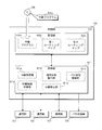
- FIG. 3 is a block diagram illustrating a configuration of the control unit 50.
- the control unit 50 includes a processing unit 61, a storage unit 62, and the like.
- the processing unit 61 is configured using an arithmetic processing device such as a CPU (Central Processing Unit) or an MPU (Micro-Processing Unit), and by reading and executing the relay program 62a stored in the storage unit 62, Arithmetic processing necessary for message relay processing and switching control processing of the bus switching unit 55 is performed.
- the processing unit 61 can exchange messages with the communication lines 11 to 13 by exchanging messages with the communication units 51 to 53.
- the processing unit 61 can output a switching signal to the bus switching unit 55 and switch the four switches SW1 to SW4 of the bus switching unit 55 to switch the communication lines 11 to 13 to the connected state or the separated state.
- the storage unit 62 is configured using a non-volatile memory element such as a flash memory or an EEPROM (Electrically Erasable Programmable Read Only Memory).
- the storage unit 62 stores a program executed by the processing unit 61 and data necessary for executing the program.
- the storage unit 62 stores a relay program 62a executed by the processing unit 61, and a first routing map 62b and a second routing map 62c used for message relay processing.
- the first routing map 62b is used when the communication lines 11 to 13 are connected in the bus switching unit 55
- the second routing map 62c is used when the communication lines 11 to 13 are in the separated state.
- the processing unit 61 includes a relay processing unit 61a, a communication state detection unit 61b, a bus switching control unit 61c, a relay rule switching unit 61d, a relay prohibition unit 61e, and the like by executing the relay program 62a. Realized as a functional block.
- the relay processing unit 61a Based on the first routing map 62b or the second routing map 62c stored in the storage unit 62, the relay processing unit 61a receives messages received from any of the communication units 51 to 53 from the other communication units 51 to 53. By transmitting, the message is relayed.
- the communication state detection unit 61b measures the amount of messages (number of bytes or number of messages, etc.) received in each communication unit 51 to 53 for a predetermined time such as 1 second or 1 millisecond, for example, the communication lines 11 to Processing for detecting 13 communication states is performed.
- the communication state detection unit 61b receives only the communication unit 51 because the communication units 52 and 53 are disconnected from the communication lines 12 and 13 when the communication lines 11 to 13 are connected by the bus switching unit 55. What is necessary is just to measure the amount of messages.
- the communication state detection unit 61b measures the message amount individually for each of the communication units 51 to 53.
- the bus switching control unit 61c performs a process of switching the switches SW1 to SW4 of the bus switching unit 55 by generating a switching signal according to the communication state detected by the communication state detecting unit 61b and outputting it to the bus switching unit 55. .
- the bus switching control unit 61c performs communication. Control is performed to switch the switches SW1 to SW4 of the bus switching unit 55 so that the lines 11 to 13 are in the separated state.
- the bus switching control unit 61c satisfies the predetermined amount of messages in each of the communication units 51 to 53 detected by the communication state detection unit 61b. If not, control is performed to switch the switches SW1 to SW4 of the bus switching unit 55 so that the communication lines 11 to 13 are connected.
- the bus switching control unit 61c performs control to shift the communication units 52 and 53 to a power saving state such as a sleep state or a standby state. As a result, the communication units 52 and 53 stop the message transmission / reception process via the communication lines 12 and 13.
- the bus switching control unit 61c changes the communication units 52 and 53 from the power saving state to the normal operation state, that is, the state for performing message transmission / reception processing. Control to be transferred.
- the relay rule switching unit 61d performs a process of switching the routing map used by the relay processing unit 61a for the relay process in accordance with the switching by the bus switching control unit 61c.
- the relay rule switching unit 61d uses the first routing map 62b stored in the storage unit 62 as a routing map for relay processing when the bus switching control unit 61c places the communication lines 11 to 13 in the connected state.
- the relay rule switching unit 61d uses the second routing map 62c stored in the storage unit 62 as a routing map used for the relay process when the bus switching control unit 61c places the communication lines 11 to 13 in the separated state.
- the relay prohibition unit 61e relays a message by the relay processing unit 61a based on the message amount per predetermined time detected by the communication state detection unit 61b when the bus switching control unit 61c places the communication lines 11 to 13 in the separated state. Perform the process to prohibit.
- the relay prohibition unit 61e with respect to the communication units 51 to 53 for which the message amount per predetermined time detected by the communication state detection unit 61b exceeds the threshold, the messages received by the communication units 51 to 53 to the other communication units 51 to 53. Relaying to 53 is prohibited.
- the “predetermined amount” that is compared with the message amount for the bus switching control unit 61c to determine switching is the same as the “threshold value” that is compared with the message amount for the relay prohibition unit 61e to determine prohibition. It may be a value or a different value. In the present embodiment, the “predetermined amount” and the “threshold value” are different values, and the “threshold value” is a value larger than the “predetermined amount”. Also, the bus switching control unit 61c compares the message amount with a “predetermined amount” for determining whether to switch from the connected state to the separated state, and the message amount for determining whether to switch from the separated state to the connected state.
- the “predetermined amount” to be compared with may be the same value or different values. In the present embodiment, it is assumed that these two “predetermined amounts” have the same value. Furthermore, the “predetermined amount” to be compared with the message amount in order to determine whether to switch from the separated state to the connected state may be a different value for each of the communication units 51 to 53.
- the gateway 5 measures the message amount for a predetermined time on the communication lines 11 to 13, and switches the switches SW1 to SW4 of the bus switching unit 55 when the message amount is less than the predetermined amount.
- the communication lines 11 to 13 are set in a connected state. That is, the gateway 5 switches the communication lines 11 to 13 from the separated state to the connected state when the communication lines 11 to 13 are in the separated state and the message amount of each of the communication lines 11 to 13 is less than the predetermined amount.
- the three communication lines 11 to 13 are electrically connected and can be regarded as one communication line. For this reason, all the ECUs 2 connected to the communication lines 11 to 13 are connected to the common communication line, and can directly transmit and receive messages via the common communication line.
- the gateway 5 shifts the communication units 52 and 53 to the power saving state and stops the message transmission / reception process.
- the gateway 5 does not need to perform message relay processing, but the communication unit 51 operates in order to measure the amount of messages transmitted and received through a common communication line (connected communication lines 11 to 13). It is necessary to keep it.
- the gateway 5 switches the switches SW1 to SW4 of the bus switching unit 55. Are switched to put the communication lines 11 to 13 in the separated state. Further, the gateway 5 shifts the communication units 52 and 53 from the power saving state to the normal operation state, and causes the communication units 52 and 53 to start message transmission / reception operations. The gateway 5 relays the message by transmitting the message received by any one of the communication units 51 to 53 from the other communication units 51 to 53.
- the gateway 5 relays messages based on the routing map.
- the gateway 5 stores the first routing map 62 b and the second routing map 62 c in the storage unit 62, and switches the routing map used for message relay processing according to the switching of the bus switching unit 55. .
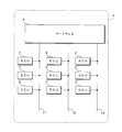
- FIG. 4 is a schematic diagram showing a configuration example of the first routing map 62b.
- FIG. 5 is a schematic diagram illustrating a configuration example of the second routing map 62c.
- the CAN ID (CAN-ID) attached to the message
- the ECU transmission ECU
- the ECU that should receive the message (reception ECU)
- the message Information such as whether or not a message relay is necessary (relay necessity), message relay source communication line (relay source communication line), message relay destination communication line (relay destination communication line), etc.
- the examples shown in FIGS. 4 and 5 are based on the network configuration shown in FIG. 2, and the plurality of ECUs 2 connected to the communication lines 11 to 13 are distinguished by reference numerals 2A to 2F shown in FIG.
- the message with 0x012 (hexadecimal number) attached to the CAN-ID is a message that needs to be transmitted by the ECU 2A connected to the communication line 11 and received by the ECU 2B connected to the communication line 11.
- the message with 0x013 added to the CAN-ID is a message that needs to be transmitted by the ECU 2A connected to the communication line 11 and received by the ECU 2C connected to the communication line 12.
- the message with 0x015 added to the CAN-ID is a message that needs to be transmitted by the ECU 2A connected to the communication line 11 and received by the ECU 2E connected to the communication line 13.
- the gateway 5 When the communication lines 11 to 13 are in the connected state, the gateway 5 performs a relay process using the first routing map 62b shown in FIG.
- the gateway 5 in the connected state, all the communication lines 11 to 13 are electrically connected, and the gateway 5 does not need to relay the message. Therefore, in the first routing map 62b, “no” is set as the necessity of relay for all messages of CAN-ID.
- the first routing map 62b may not be stored in the storage unit 62. .
- the gateway 5 When the communication lines 11 to 13 are in the separated state, the gateway 5 performs a relay process using the second routing map 62c shown in FIG.
- the second routing map 62c both the transmission source ECU 2A and the reception destination ECU 2B are connected to the communication line 11 for the message with CAN-ID 0x12, and can be directly transmitted and received between the ECUs 2A and 2B. Therefore, “No” is set in the necessity of relay, and the gateway 5 does not relay this message.
- the transmission source ECU 2A is connected to the communication line 11
- the reception destination ECU 2C is connected to the communication line 12. The gateway 5 relays this message from the communication line 11 to the communication line 12.
- the message with CAN-ID 0x15 is set to “necessary” for the necessity of relay because the ECU 2A of the transmission source is connected to the communication line 11 and the ECU 2E of the reception destination is connected to the communication line 13.
- the gateway 5 relays this message from the communication line 11 to the communication line 13.
- the gateway 5 switches the routing map used for the message relay process in accordance with the switching of the connection state and the separation state of the communication lines 11 to 13 by the bus switching unit 55, whereby the network configuration of the communication lines 11 to 13 is achieved. It is possible to appropriately carry out message relay processing in response to changes in In the case of this example, when the communication lines 11 to 13 are in the connected state, the message relay is not required. However, the present invention is not limited to this. For example, in the connected state, only the communication lines 11 and 12 are connected. The communication line 13 may be connected and the communication line 13 may not be connected. In such a case, the first routing map 62b includes the ECU 2 connected to the communication line 11 or 12 and the ECU 2 connected to the communication line 13. An appropriate value is set to relay the message.
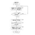
- FIG. 6 is a flowchart showing a procedure of processing performed by the gateway 5 when the communication lines 11 to 13 are connected.
- the communication state detection unit 61b of the processing unit 61 of the control unit 50 of the gateway 5 measures the amount of messages received by the communication unit 51 at a predetermined time (step S1).
- the bus switching control unit 61c of the processing unit 61 determines whether or not the message amount measured in step S1 exceeds a predetermined amount (step S2).
- the processing unit 61 returns the processing to step S1, and repeats measurement of the message amount and determination with the predetermined amount.
- the bus switching control unit 61c switches the switches SW1 to SW4 by outputting a switching signal to the bus switching unit 55, and the communication lines 11 to 13 is switched to the separated state (step S3). Further, the relay rule switching unit 61d of the processing unit 61 switches the routing map used for the relay process from the first routing map 62b to the second routing map 62c (step S4). In addition, the processing unit 61 starts the communication units 52 and 53 connected to the communication lines 12 and 13 by switching the bus switching unit 55 from the power saving state and shifts to the normal operation state (step S5). Terminate the process.
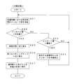
- FIG. 7 is a flowchart showing a procedure of processing performed by the gateway 5 when the communication lines 11 to 13 are in the separated state.
- the communication state detection unit 61b of the processing unit 61 of the control unit 50 of the gateway 5 measures the amount of messages received by each of the communication units 51 to 53 in a predetermined time (step S21).
- the bus switching control unit 61c of the processing unit 61 determines whether or not the measured message amount of each of the communication units 51 to 53 measured in step S21 is less than a predetermined amount (step S22).
- the relay prohibition unit 61e of the processing unit 61 sets the message amount measured in step S21 to a threshold (> predetermined amount). It is further determined whether or not it exceeds (step S23). When the message amount exceeds the threshold (S23: YES), the relay prohibition unit 61e prohibits relaying of the message received by the communication units 51 to 53 whose message amount exceeds the threshold (step S24), and proceeds to step S21. Return processing. If the message amount does not exceed the threshold (S23: NO), the relay prohibition unit 61e returns the process to step S21.
- the bus switching control unit 61c switches the switches SW1 to SW4 by outputting a switching signal to the bus switching unit 55.
- the communication lines 11 to 13 are switched to the connected state (step S25).
- the relay rule switching unit 61d of the processing unit 61 switches the routing map used for the relay process from the second routing map 62c to the first routing map 62b (step S26).
- the processing unit 61 shifts the communication units 52 and 53 disconnected from the communication lines 12 and 13 by switching the bus switching unit 55 from the normal operation state to the power saving state (step S27), and performs processing in the separated state. finish.
- the switch of the bus switching unit 55 is switched to a connection state in which the three communication lines 11 to 13 connected to the gateway 5 are directly connected or in a separated state. Switch using SW1 to SW4.
- the ECU 2 connected to the communication lines 11 to 13 can directly transmit / receive messages to / from other ECUs 2 without relaying messages by the gateway 5. It becomes.
- the bus switching unit 55 switches to the connected state, the communication units 52 and 53 that transmit and receive messages to and from the communication lines 11 to 13 do not need to operate, and shift to the power saving state to reduce power consumption. It becomes possible to reduce.
- the communication line 11 to 13 can be separated by the bus switching unit 55, so that the communication load can be distributed and reduced. it can.
- the connection / separation of the communication lines 11 to 13 changes the network configuration in the communication system. Therefore, the gateway 5 switches the message relay rule according to the network configuration, that is, according to the switching state of the bus switching unit 55. Specifically, the gateway 5 stores a plurality of routing maps in which the message and the relay destination of the message are associated with each other in the storage unit 62, and stores the first routing map stored in the storage unit 62 according to the switching state of the bus switching unit 55. A message is relayed by selecting and using either the first routing map 62b or the second routing map 62c.
- the gateway 5 detects the communication state of the communication lines 11 to 13, for example, the message amount in a predetermined time, and switches the switches SW1 to SW4 of the bus switching unit 55 according to the detected communication state. At this time, the gateway 5 detects a common communication state for the plurality of communication lines 11 to 13 in the connected state, and individually detects a communication state for the communication lines 11 to 13 in the separated state. For example, when the message amount is less than a predetermined amount, the gateway 5 switches the bus switching unit 55 to place the plurality of communication lines 11 to 13 in the connected state, and sets the separated state when the message amount exceeds the predetermined amount.
- the communication lines 11 to 13 are connected to reduce the power consumption of the communication ICs constituting the communication units 52 and 53, and when the message amount is large, the plurality of communication lines 11 to 13 are connected.
- the communication load can be reduced by distributing the communication lines 11 to 13 in a separated state.
- the gateway 5 detects the message amount for each of the separated communication lines 11 to 13 after switching the switches SW1 to SW4 of the bus switching unit 55 to the separated state when the message amount exceeds a predetermined amount.
- the gateway 5 relays the message received on the communication lines 11 to 13 to the other communication lines 11 to 13. Is prohibited.
- an unauthorized communication device connected to any one of the communication lines 11 to 13 performs an attack in which a large number of messages are transmitted, the communication lines 11 to 13 are disconnected from the communication system and are transferred to the entire system. Can be reduced.
- the gateway 5 is configured to switch all three communication lines 11 to 13 by connecting the switches SW1 to SW4 of the bus switching unit 55.
- the present invention is not limited to this. Absent.
- the gateway 5 has a configuration in which the switches SW1 and SW2 and the switches SW3 and SW4 of the bus switching unit 55 can be switched independently, and the communication lines 11 and 12 are connected and the communication line 13 is separated, or the communication It is good also as a structure which can be switched to the state etc. which connected the lines 11 and 13 and isolate
- the present invention is not limited to this, and a configuration in which two or four or more communication lines are connected may be used.
- the configuration of the routing map and the set values shown in FIGS. 4 and 5 are examples, and the present invention is not limited to this.
- the communication system according to the present embodiment is mounted on the vehicle 1, it is not limited to this.
- the communication system may be mounted on a mobile body such as a ship or an aircraft other than the vehicle 1, or may be installed in a home, factory, school, office, or the like other than the mobile body.
- the gateway 5 is configured to switch the switches SW1 to SW4 of the bus switching unit 55 according to the message amount of the communication lines 11 to 13 for a predetermined time.
- the configuration is not limited to this, and the configuration is performed for switching under other conditions. It is good.
- the gateway 5 can be configured to switch the switches SW1 to SW4 of the bus switching unit 55 in accordance with the on / off state of the IG (ignition) switch of the vehicle 1. In this configuration, for example, the gateway 5 places the communication lines 11 to 13 in the connected state when the IG switch is off, and places the communication lines 11 to 13 in the separated state when the IG switch is on.
- the gateway 5 can shift the communication units 52 and 53 to the power saving state by setting the communication lines 11 to 13 in the connected state in the state where the IG switch is turned off and the engine of the vehicle 1 is stopped. Consumption of power stored in the battery can be reduced. Further, the gateway 5 can distribute the communication load by setting the communication lines 11 to 13 in the separated state in a state where the IG switch is turned on and the ECU 2 mounted on the vehicle 1 is likely to operate to increase the amount of messages. it can.
- the processing unit 61 is not configured as a CPU that executes the program and performs processing, and the processing is hardware-like.
- the relay program 62a does not need to be stored in the storage unit 62.
- the processing unit 61 reads and executes the relay program 62a stored in the storage unit 62
- the relay program 62a is stored in the storage unit 62 before being mounted on the circuit board in the manufacturing process of the gateway 5, for example. On the other hand, it may be written directly, or may be written using the communication function of the gateway 5.
- the relay program 62a is provided by being recorded on a recording medium 99 such as a memory card or an optical disk, and is relayed from the recording medium 99 by a device such as a memory card slot or an optical disk drive provided in the gateway 5 or the vehicle 1. May be read and written to the storage unit 62.
- a recording medium 99 such as a memory card or an optical disk
- a device such as a memory card slot or an optical disk drive provided in the gateway 5 or the vehicle 1. May be read and written to the storage unit 62.
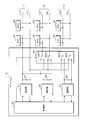
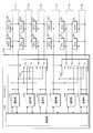
- FIG. 8 is a schematic diagram illustrating a configuration of the gateway 105 according to the modification.
- Six communication lines 111 to 116 are connected to the gateway 105 according to the modification.
- ECUs 2A and 2B are connected to the communication line 111
- ECUs 2C and 2D are connected to the communication line 112
- ECUs 2E and 2F are connected to the communication line 113.
- ECUs 2G and 2H are connected to the communication line 114
- ECUs 2I and 2J are connected to the communication line 115
- ECUs 2K and 2L are connected to the communication line 116.
- the gateway 105 according to the modification includes a control unit 150, six communication units 151 to 156, and two bus switching units 157 and 158.
- the configuration of the gateway 105 according to the modification corresponds to a configuration including two sets of switching control configurations by the communication units 51 to 53 and the bus switching unit 55 included in the gateway 5 illustrated in FIG. That is, the gateway 105 according to the modified example switches the connection state / separation state of the communication lines 111 to 113 by the communication units 151 to 153 and the bus switching unit 157, and the communication line 114 to the communication units 154 to 156 and the bus switching unit 158. The connection state / separation state of .about.116 is switched.
- the control unit 150 of the gateway 105 detects the message amount of the communication lines 111 to 113 in the communication units 151 to 153, and switches the switch of the bus switching unit 157 according to the detection result. Control is performed to switch 111 to 113 to the connected state or the separated state. In addition, the control unit 150 detects the message amount of the communication lines 114 to 156 in the communication units 154 to 156, and switches the switch of the bus switching unit 158 according to the detection result, thereby connecting the communication lines 114 to 116 to the connected state. Alternatively, control to switch to the separated state is performed.
- control unit 150 can independently control switching of the connection state / separation state of the communication lines 111 to 113 and switching of the connection state / separation state of the communication lines 114 to 116.
- the message relay process performed by the control unit 150 can relay a message received on any of the six communication lines 111 to 116 to any of the six communication lines 111 to 116. Therefore, the control unit 150 of the gateway 105 according to the modified example displays four routing maps according to the combination of the connection state / separation state of the communication lines 111 to 113 and the connection state / separation state of the communication lines 114 to 116. It is stored in the storage unit.
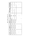
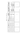
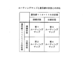
- FIG. 9 is a table showing the correspondence between the routing map stored in the gateway 105 according to the modification and the states of the communication lines 111 to 116.
- the gateway 105 according to the modified example stores four routing maps, a first routing map to a fourth routing map.
- the gateway 105 performs message relay processing using the first routing map.
- the gateway 105 performs message relay processing using the second routing map.
- the gateway 105 performs message relay processing using the third routing map.
- the gateway 105 performs message relay processing using the fourth routing map.
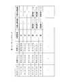
- FIG. 10 is a schematic diagram illustrating a configuration example of the first routing map according to the modification.
- the gateway 105 according to the modified example performs message relay processing using the illustrated first routing map when the communication lines 111 to 113 are in a connected state and the communication lines 114 to 116 are in a connected state. Since the communication lines 111 to 113 are connected and the communication lines 114 to 116 are connected, the communication system in this state is substantially equivalent to a state where the ECUs 2A to 2L are connected to the two communication lines.
- a message transmitted by the ECU 2A connected to one communication line 111 is directly received by the ECUs 2B to 2F without being relayed by the gateway 105, or is relayed by the gateway 105 and connected to the other communication line 114. Is received by the ECUs 2G to 2L.
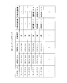
- FIG. 11 is a schematic diagram showing a configuration example of the second routing map according to the modification.
- the gateway 105 according to the modification performs message relay processing using the illustrated second routing map when the communication lines 111 to 113 are in the separated state and the communication lines 114 to 116 are in the connected state. Since the communication lines 111 to 113 are in the separated state and the communication lines 114 to 116 are in the connected state, the communication system in this state is substantially equivalent to a state in which the ECUs 2A to 2L are connected to the four communication lines.
- the message transmitted by the ECU 2A connected to the communication line 111 is directly received by the ECU 2B connected to the communication line 11 without being relayed by the gateway 105, or is relayed by the gateway 105 to the communication line 112 or 113. It is received by the connected ECUs 2C to 2F or received by the ECUs 2G to 2L relayed by the gateway 105 and connected to the connected communication line 114.
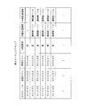
- FIG. 12 is a schematic diagram illustrating a configuration example of a third routing map according to the modification.
- the gateway 105 according to the modification performs message relay processing using the illustrated third routing map when the communication lines 111 to 113 are in a connected state and the communication lines 114 to 116 are in a separated state. Since the communication lines 111 to 113 are connected and the communication lines 114 to 116 are separated, the communication system in this state is substantially equivalent to a state where the ECUs 2A to 2L are connected to the four communication lines.
- the message transmitted by the ECU 2A connected to the communication line 111 is directly received by the ECUs 2B to 2F without being relayed by the gateway 105, or is relayed by the gateway 105 to any one of the communication lines 114 to 116. It is received by the connected ECUs 2G to 2L.
- FIG. 13 is a schematic diagram illustrating a configuration example of a fourth routing map according to the modification.
- the gateway 105 When the communication lines 111 to 113 are in the separated state and the communication lines 114 to 116 are in the separated state, the gateway 105 according to the modified example performs message relay processing using the illustrated fourth routing map. Since all the communication lines 111 to 116 are in the separated state, the gateway 105 relays messages between the six communication lines 111 to 116 in the communication system in this state.
- the gateway 105 is configured to switch the connection state / separation state by dividing the six communication lines 111 to 116 into two sets of three.
- the number of communication lines, the number of groupings, and the like for switching the connection state / separation state by the gateway are not limited to those shown in the present modification, and various configurations can be employed.
Landscapes
- Engineering & Computer Science (AREA)
- Computer Networks & Wireless Communication (AREA)
- Signal Processing (AREA)
- Small-Scale Networks (AREA)
Abstract
The present invention provides a relay device, a relay method and a relay program that are able to suppress an increase in power consumption accompanying the operation of an IC for communication or the like. A relay device according to the present embodiment is provided with a relay unit to which a plurality of communication lines are connected and which transmits a message received from one communication line to another communication line, thereby relaying the message, the relay device being provided with a switch for switching at least two communication lines included in the plurality of communication lines to a connected state in which the communication lines are directly connected or a separated state in which the communication lines are individually separated, and a relay rule switching unit for switching a message relay rule of the relay unit in accordance with the switching state of the switch. The relay device is further provided with a communication state detection unit for detecting the communication states of the communication lines, and switches the switch in accordance with the communication states detected by the communication state detection unit.
Description
本発明は、複数の通信線間のメッセージ送受信を中継する処理を行う中継装置、中継方法及び中継プログラムに関する。
The present invention relates to a relay apparatus, a relay method, and a relay program that perform processing for relaying message transmission / reception between a plurality of communication lines.
特許文献1においては、複数のCAN(Controller Area Network)バスに接続されたゲートウェイノードが、重要なフレームの通信遅延、受信抜けの発生及び低優先度IDの送信遅延発生を抑制することを目的としたネットワークシステムが提案されている。このネットワークシステムでは、ゲートウェイノードがCANバスの負荷状態を監視し、バス負荷状態に応じてバス負荷の調整を行う。バス負荷の調整は、ゲートウェイノードが中継処理を減らす、中継フレームのデータ長を減らす、他ノードがフレームの送信周期を長くする、又は、送信フレームのデータ長を減らす等により行われる。
In Patent Document 1, a gateway node connected to a plurality of CAN (Controller Area Network) buses is intended to suppress communication delay of important frames, occurrence of reception omission and transmission delay of low priority ID. A network system has been proposed. In this network system, the gateway node monitors the load state of the CAN bus and adjusts the bus load according to the bus load state. The bus load is adjusted by reducing the relay processing by the gateway node, reducing the data length of the relay frame, increasing the frame transmission cycle by another node, or reducing the data length of the transmission frame.
特許文献2においては、CANコントローラがネットワークのバス負荷率を算出し、バス負荷率に基づいてネットワークの負荷の高低を判定し、高負荷である旨の判定結果に基づいて通信メッセージの送信を自ら規制する通信装置が提案されている。
In Patent Document 2, the CAN controller calculates the bus load factor of the network, determines the level of the network load based on the bus load factor, and transmits the communication message itself based on the determination result indicating that the load is high. Communication devices to be regulated have been proposed.
複数の通信線が接続される中継装置には、通信線毎にメッセージの送受信を行う通信用のIC(Integrated Circuit)などが設けられる。中継装置に接続される通信線の増加に伴って、中継装置に搭載される通信用ICの数は増加し、複数の通信用ICの動作に伴う消費電力量が増大するという問題がある。特許文献1に記載のネットワークシステムでも同様の問題が発生し得る。
A relay device to which a plurality of communication lines are connected is provided with a communication IC (Integrated Circuit) that transmits and receives messages for each communication line. As the number of communication lines connected to the relay device increases, the number of communication ICs mounted on the relay device increases, and there is a problem that the amount of power consumed by the operation of the plurality of communication ICs increases. The same problem can occur in the network system described in Patent Document 1.
また、例えば通信線に不正な通信装置を接続し、この不正な通信装置が大量のメッセージを通信線へ送信することによって、正規の通信装置によるメッセージの送受信を妨害するというような悪意の攻撃を通信システムが受ける可能性がある。特許文献1,2に記載の発明では、バス負荷に応じて通信量を低減することが行われるが、不正な通信装置が大量のメッセージを送信するという攻撃に対応することは難しい。
In addition, for example, an unauthorized communication device is connected to a communication line, and the unauthorized communication device transmits a large number of messages to the communication line, thereby preventing a malicious attack such as preventing transmission and reception of messages by a legitimate communication device. There is a possibility that the communication system is affected. In the inventions described in Patent Documents 1 and 2, the amount of communication is reduced according to the bus load, but it is difficult to cope with an attack in which an unauthorized communication device transmits a large number of messages.
本発明は、斯かる事情に鑑みてなされたものであって、その目的とするところは、通信用ICなどの動作に伴う消費電力量の増大を抑制し得る中継装置及び中継方法を提供することにある。また他の目的とするところは、不正な通信装置が大量のメッセージを送信するという攻撃によるシステム全体への影響を低減することができる中継装置、中継方法及び中継プログラムを提供することにある。
The present invention has been made in view of such circumstances, and an object of the present invention is to provide a relay device and a relay method capable of suppressing an increase in power consumption accompanying the operation of a communication IC or the like. It is in. Another object of the present invention is to provide a relay device, a relay method, and a relay program that can reduce the influence on the entire system due to an attack in which an unauthorized communication device transmits a large number of messages.
本発明に係る中継装置は、複数の通信線が接続され、一の通信線にて受信したメッセージを他の通信線から送信することで該メッセージを中継する中継部を備える中継装置において、前記複数の通信線に含まれる少なくとも2つの通信線を接続する接続状態又は前記通信線を個別に分離する分離状態に切り替えるスイッチと、前記スイッチの切替状態に応じて前記中継部によるメッセージの中継規則を切り替える中継規則切替部とを備えることを特徴とする。
The relay device according to the present invention is a relay device comprising a relay unit to which a plurality of communication lines are connected and a message received on one communication line is transmitted from another communication line to relay the message. A switch that switches to a connection state in which at least two communication lines included in the communication line are connected or a separation state in which the communication lines are individually separated, and the relay rule of the message by the relay unit is switched according to the switching state of the switch And a relay rule switching unit.
また、本発明に係る中継装置は、前記通信線の通信状態を検出する通信状態検出部を備え、前記通信状態検出部が検出した通信状態に応じて前記スイッチを切り替えることを特徴とする。
The relay device according to the present invention includes a communication state detection unit that detects a communication state of the communication line, and switches the switch according to the communication state detected by the communication state detection unit.
また、本発明に係る中継装置は、前記通信状態検出部が、前記通信線を介して送受信されるメッセージの量を検出し、前記メッセージの量が所定量に満たない場合に前記スイッチを接続状態に切り替え、前記メッセージの量が所定量を超える場合に前記スイッチを分離状態に切り替えることを特徴とする。
In the relay device according to the present invention, the communication state detection unit detects the amount of messages transmitted / received via the communication line, and the switch is connected when the amount of the messages is less than a predetermined amount. When the amount of the message exceeds a predetermined amount, the switch is switched to a separated state.
また、本発明に係る中継装置は、前記スイッチを分離状態に切り替えた後に前記通信状態検出部が検出するメッセージの量が第2所定量を超える通信線にて受信したメッセージを前記中継部が他の通信線へ中継することを禁止する中継禁止部を備えることを特徴とする。
In the relay device according to the present invention, the relay unit may receive a message received on a communication line in which the amount of messages detected by the communication state detection unit exceeds a second predetermined amount after the switch is switched to the separated state. A relay prohibiting unit that prohibits relaying to the communication line is provided.
また、本発明に係る中継装置は、メッセージと該メッセージの中継先とが対応付けられた中継用情報を複数記憶した記憶部を備え、前記スイッチの切替状態に応じて前記記憶部からいずれか1つの中継用情報を読み出すことによりメッセージの中継規則を切り替えることを特徴とする。
In addition, the relay device according to the present invention includes a storage unit that stores a plurality of pieces of relay information in which a message and a relay destination of the message are associated with each other, and any one from the storage unit according to a switching state of the switch. The relay rule of the message is switched by reading one relay information.
また、本発明に係る中継方法は、複数の通信線が接続され、一の通信線にて受信したメッセージを他の通信線から送信することで該メッセージを中継する中継装置が、前記複数の通信線に含まれる少なくとも2つの通信線を接続する接続状態又は前記通信線を個別に分離する分離状態に切り替え、切替状態に応じてメッセージの中継規則を切り替えることを特徴とする。
In the relay method according to the present invention, a plurality of communication lines are connected, and a relay apparatus that relays the message by transmitting a message received on one communication line from another communication line includes the plurality of communication lines. It is switched to a connection state in which at least two communication lines included in the line are connected or to a separation state in which the communication lines are individually separated, and a message relay rule is switched according to the switching state.
また、本発明に係る中継プログラムは、複数の通信線が接続され、一の通信線にて受信したメッセージを他の通信線から送信することで該メッセージを中継する中継部、及び、前記複数の通信線に含まれる少なくとも2つの通信線を接続する接続状態又は前記通信線を個別に分離する分離状態に切り替えるスイッチを有する中継装置に、前記通信線の通信状態に応じて前記スイッチを切り替えさせ、前記スイッチの切替状態に応じて前記中継部によるメッセージの中継規則を切り替えさせることを特徴とする。
The relay program according to the present invention includes a relay unit that connects a plurality of communication lines, relays the message by transmitting a message received on one communication line from another communication line, and the plurality of the plurality of communication lines. In a relay apparatus having a switch that switches to a connection state that connects at least two communication lines included in the communication line or a separation state that separates the communication lines individually, the switch is switched according to the communication state of the communication line, The relay rule of the message by the relay unit is switched according to the switching state of the switch.
本発明においては、中継装置に接続される複数の通信線に含まれる少なくとも2つの通信線を、直接的に接続する接続状態又は個別に分離する分離状態にスイッチを用いて切り替える。直接的に接続された通信線では、中継装置によるメッセージの中継を行うことなく、メッセージの送受信を行うことが可能となる。このため、スイッチにて接続状態へ切り替えられた場合、通信線に対するメッセージの送受信を行う通信用ICは動作する必要がなく、スリープ状態又はスタンバイ状態等の低消費電力状態へ移行し、消費電力量を低減することが可能となる。また接続状態となった通信線においてメッセージの送受信量が増加した場合には、スイッチにて通信線を個別に分離状態とすることによって、通信負荷を分散して低減することができる。
このような通信線の接続/分離を行うことによって、通信システム中のネットワーク構成が変化する。このため中継装置は、ネットワーク構成に応じて、即ちスイッチの切替状態に応じて、メッセージの中継規則を切り替える。例えば中継装置は、メッセージとこのメッセージを中継する中継先とを対応付けた中継用情報、いわゆるルーティングマップ又はルーティングテーブル等の情報を複数記憶しておき、スイッチの切替状態に応じていずれか1つの中継用情報を用いてメッセージの中継を行うことにより、メッセージの中継規則を切り替えることができる。 In the present invention, at least two communication lines included in a plurality of communication lines connected to the relay apparatus are switched using a switch to a connection state in which they are directly connected or a separation state in which they are individually separated. With a directly connected communication line, it is possible to send and receive messages without relaying messages by a relay device. For this reason, when the switch is switched to the connected state, the communication IC that transmits and receives messages to and from the communication line does not need to operate, and shifts to a low power consumption state such as a sleep state or a standby state. Can be reduced. Further, when the amount of message transmission / reception increases on the communication line in the connected state, the communication load can be distributed and reduced by individually setting the communication line in the separated state by the switch.
By connecting / disconnecting such communication lines, the network configuration in the communication system changes. Therefore, the relay apparatus switches the message relay rule according to the network configuration, that is, according to the switch switching state. For example, the relay apparatus stores a plurality of pieces of information such as a so-called routing map or a routing table in which a message is associated with a relay destination that relays the message, and any one of them according to the switching state of the switch. Message relay rules can be switched by relaying messages using relay information.
また本発明においては、通信線の通信状態を検出し、検出した通信状態に応じてスイッチを切り替える。このときに中継装置は、接続状態にある複数の通信線については共通の通信状態を検出し、分離状態にある通信線については個別に通信状態を検出する。検出する通信状態は、例えば所定時間において送受信されたメッセージの量とすることができる。
中継装置は、例えばメッセージ量が所定量に満たない場合にスイッチを切り替えて複数の通信線を接続状態とし、メッセージ量が所定量を超える場合に分離状態とする。メッセージ量が少ない場合には複数の通信線を接続状態とすることで通信用ICなどの消費電力量を低減し、メッセージ量が多い場合には複数の通信線を分離状態として通信負荷を分散して低減することができる。 Moreover, in this invention, the communication state of a communication line is detected and a switch is switched according to the detected communication state. At this time, the relay device detects a common communication state for a plurality of communication lines in a connected state, and individually detects a communication state for a communication line in a separated state. The communication state to be detected can be, for example, the amount of messages transmitted / received in a predetermined time.
For example, when the message amount is less than a predetermined amount, the relay device switches the switch to connect the plurality of communication lines, and when the message amount exceeds the predetermined amount, the relay device is set to the separated state. When the amount of messages is small, the power consumption of the communication IC is reduced by connecting multiple communication lines, and when the amount of messages is large, the communication load is distributed by separating the multiple communication lines. Can be reduced.
また本発明において中継装置は、メッセージ量が所定量を超えるためにスイッチを分離状態に切り替えた後、分離された各通信線について通信状態の検出を行う。検出されたメッセージ量が第2所定量を超える通信線が存在する場合、中継装置は、この通信線にて受信したメッセージを他の通信線へ中継することを禁止する。これにより、いずれかの通信線に接続された不正な通信装置が大量のメッセージを送信するという攻撃を行った場合に、この通信線をシステムから切り離して、システム全体への影響を低減することができる。なお第2所定量は、スイッチ切替の判断基準となる所定量と同じ値であってもよく、異なる値であってもよい。
In the present invention, the relay device detects the communication state of each separated communication line after switching the switch to the separated state because the message amount exceeds a predetermined amount. When there is a communication line whose detected message amount exceeds the second predetermined amount, the relay device prohibits relaying a message received on this communication line to another communication line. As a result, when an unauthorized communication device connected to one of the communication lines performs an attack that sends a large amount of messages, this communication line can be disconnected from the system to reduce the impact on the entire system. it can. The second predetermined amount may be the same value as or a different value from the predetermined amount serving as a switch switching determination criterion.
本発明による場合は、複数の通信線を接続状態に切り替えるスイッチを備えることにより、通信用ICなどの動作に伴う消費電力量の増大を抑制することができる。また本発明による場合は、分離状態とされた通信線のメッセージ量が第2所定量を超える場合にこの通信線からのメッセージの中継を禁止する構成とすることにより、不正な通信装置が大量のメッセージを送信するという攻撃によるシステム全体への影響を低減することができる。
In the case of the present invention, an increase in power consumption associated with the operation of the communication IC or the like can be suppressed by providing a switch for switching a plurality of communication lines to a connected state. Further, in the case of the present invention, when the message amount of the communication line in the separated state exceeds the second predetermined amount, the relay of the message from this communication line is prohibited so that a large number of unauthorized communication devices can be obtained. It is possible to reduce the influence on the entire system by the attack of sending a message.
<システム構成>
図1は、本実施の形態に係る通信システムの構成を示す模式図である。本実施の形態に係る通信システムは、破線で示す車両1に搭載された複数のECU2が、車両1に搭載された複数の通信線11~13及びゲートウェイ5を介してメッセージの送受信を行う構成である。詳しくは、車両1には複数のバス型の通信線11~13が適所に配設されており、この通信線11~13はゲートウェイ5に接続されている。各通信線11~13には、一又は複数のECU(Electronic Control Unit)2が接続されている。ゲートウェイ5は、通信線11~13間のメッセージの中継処理を行うことにより、異なる通信線11~13に接続されたECU2間のメッセージ送受信を中継する。 <System configuration>
FIG. 1 is a schematic diagram showing a configuration of a communication system according to the present embodiment. The communication system according to the present embodiment has a configuration in which a plurality ofECUs 2 mounted on a vehicle 1 indicated by broken lines transmit and receive messages via a plurality of communication lines 11 to 13 and a gateway 5 mounted on the vehicle 1. is there. Specifically, the vehicle 1 is provided with a plurality of bus-type communication lines 11 to 13 at appropriate positions, and the communication lines 11 to 13 are connected to the gateway 5. One or a plurality of ECUs (Electronic Control Units) 2 are connected to each of the communication lines 11 to 13. The gateway 5 relays message transmission / reception between ECUs 2 connected to different communication lines 11 to 13 by relaying messages between the communication lines 11 to 13.
図1は、本実施の形態に係る通信システムの構成を示す模式図である。本実施の形態に係る通信システムは、破線で示す車両1に搭載された複数のECU2が、車両1に搭載された複数の通信線11~13及びゲートウェイ5を介してメッセージの送受信を行う構成である。詳しくは、車両1には複数のバス型の通信線11~13が適所に配設されており、この通信線11~13はゲートウェイ5に接続されている。各通信線11~13には、一又は複数のECU(Electronic Control Unit)2が接続されている。ゲートウェイ5は、通信線11~13間のメッセージの中継処理を行うことにより、異なる通信線11~13に接続されたECU2間のメッセージ送受信を中継する。 <System configuration>
FIG. 1 is a schematic diagram showing a configuration of a communication system according to the present embodiment. The communication system according to the present embodiment has a configuration in which a plurality of
ECU2は、例えば車両1のエンジンの動作を制御するECU、ドアのロック/アンロックを制御するECU、ライトの点灯/消灯を制御するECU、エアバッグの動作を制御するECU、及び、ABS(Antilock Brake System)の動作を制御するECU等の種々のECUが含まれ得る。各ECU2は、車両1に配された通信線11~13のいずれかに接続され、通信線11~13及びゲートウェイ5を介して他のECU2との間でメッセージの送受信を行うことができる。
The ECU 2 includes, for example, an ECU that controls the operation of the engine of the vehicle 1, an ECU that controls the locking / unlocking of the door, an ECU that controls the turning on / off of the light, an ECU that controls the operation of the airbag, and an ABS (Antilock Various ECUs such as an ECU for controlling the operation of the Brake System may be included. Each ECU 2 is connected to any one of the communication lines 11 to 13 arranged in the vehicle 1, and can send and receive messages to and from other ECUs 2 through the communication lines 11 to 13 and the gateway 5.
ゲートウェイ5は、車両1の車内ネットワークを構成する複数の通信線11~13が接続され、通信線11~13間のメッセージの送受信を中継する処理を行う。図1に示す例においては、ゲートウェイ5には3つの通信線11~13が接続され、各通信線11~13にはそれぞれ3つのECU2が接続されている。ただしゲートウェイ5に接続される通信線11~13の数及び各通信線11~13に接続されるECU2の数は一例であり、これに限るものではない。ゲートウェイ5は、いずれかの通信線11~13にて受信したメッセージを、他の通信線11~13へ送信することによって、メッセージの中継を行うことができる。
The gateway 5 is connected to a plurality of communication lines 11 to 13 constituting the in-vehicle network of the vehicle 1 and performs a process of relaying message transmission / reception between the communication lines 11 to 13. In the example shown in FIG. 1, three communication lines 11 to 13 are connected to the gateway 5, and three ECUs 2 are connected to each of the communication lines 11 to 13, respectively. However, the number of communication lines 11 to 13 connected to the gateway 5 and the number of ECUs 2 connected to the communication lines 11 to 13 are merely examples, and are not limited thereto. The gateway 5 can relay the message by transmitting the message received on any one of the communication lines 11 to 13 to the other communication lines 11 to 13.
なお本実施の形態に係る通信システムにおいては、ECU2及びゲートウェイ5はCAN(Controller Area Network)の通信プロトコルに従ってメッセージの送受信を行う。ただしECU2及びゲートウェイ5がCAN以外の通信プロトコル、例えばFlexRay又はLIN(Local Interconnect Network)等の通信プロトコルに従ってメッセージの送受信を行う構成としてもよい。ECU2及びゲートウェイ5は、少なくともバス型の通信線を介してメッセージの送受信を行う構成であればよい。
In the communication system according to the present embodiment, the ECU 2 and the gateway 5 transmit and receive messages in accordance with a CAN (Controller Area Network) communication protocol. However, the ECU 2 and the gateway 5 may be configured to transmit and receive messages according to a communication protocol other than CAN, for example, a communication protocol such as FlexRay or LIN (Local Interconnect Network). The ECU 2 and the gateway 5 may be configured to transmit and receive messages via at least a bus-type communication line.
<装置構成>
図2は、ゲートウェイ5の構成を示す模式図である。本実施の形態に係るゲートウェイ5は、制御部50、通信部51~53及びバス切替部55等を備えて構成されている。本実施の形態においては通信プロトコルとしてCANが採用されており、CANの通信プロトコルにおける通信線11~13(いわゆるCANバス)は2線式である。このため本図においては、第1通信線11H及び第2通信線11Lの2本で通信線11が構成され、第1通信線12H及び第2通信線12Lの2本で通信線12が構成され、第1通信線13H及び第2通信線13Lの2本で通信線13が構成されているものとする。また本図においては、通信線11に接続されたECU2をECU2A及び2Bとし、通信線12に接続されたECU2をECU2C及び2Dとし、通信線13に接続されたECU2をECU2E及び2Fとして区別する。 <Device configuration>
FIG. 2 is a schematic diagram showing the configuration of thegateway 5. The gateway 5 according to the present embodiment includes a control unit 50, communication units 51 to 53, a bus switching unit 55, and the like. In the present embodiment, CAN is adopted as a communication protocol, and communication lines 11 to 13 (so-called CAN bus) in the CAN communication protocol are two-wire. For this reason, in this figure, the communication line 11 is comprised by the two of the 1st communication line 11H and the 2nd communication line 11L, and the communication line 12 is comprised by the two of the 1st communication line 12H and the 2nd communication line 12L. It is assumed that the communication line 13 is composed of two lines, the first communication line 13H and the second communication line 13L. In this figure, the ECU 2 connected to the communication line 11 is identified as ECUs 2A and 2B, the ECU 2 connected to the communication line 12 is identified as ECUs 2C and 2D, and the ECU 2 connected to the communication line 13 is identified as ECUs 2E and 2F.
図2は、ゲートウェイ5の構成を示す模式図である。本実施の形態に係るゲートウェイ5は、制御部50、通信部51~53及びバス切替部55等を備えて構成されている。本実施の形態においては通信プロトコルとしてCANが採用されており、CANの通信プロトコルにおける通信線11~13(いわゆるCANバス)は2線式である。このため本図においては、第1通信線11H及び第2通信線11Lの2本で通信線11が構成され、第1通信線12H及び第2通信線12Lの2本で通信線12が構成され、第1通信線13H及び第2通信線13Lの2本で通信線13が構成されているものとする。また本図においては、通信線11に接続されたECU2をECU2A及び2Bとし、通信線12に接続されたECU2をECU2C及び2Dとし、通信線13に接続されたECU2をECU2E及び2Fとして区別する。 <Device configuration>
FIG. 2 is a schematic diagram showing the configuration of the
通信線11は、ゲートウェイ5の通信部51に接続されている。また通信線11を構成する第1通信線11H及び第2通信線11Lは、通信部51の近傍で、終端抵抗器R1を介して接続されている。通信線12及び13は、ゲートウェイ5のバス切替部55にそれぞれ接続されている。バス切替部55は、4つのスイッチSW1~SW4を有しており、通信線12及び13を、通信線11か、又は、通信部52及び53かのいずれかに、スイッチSW1~SW4の切り替えによって選択的に接続する。
The communication line 11 is connected to the communication unit 51 of the gateway 5. The first communication line 11H and the second communication line 11L constituting the communication line 11 are connected in the vicinity of the communication unit 51 via the termination resistor R1. The communication lines 12 and 13 are respectively connected to the bus switching unit 55 of the gateway 5. The bus switching unit 55 has four switches SW1 to SW4, and the communication lines 12 and 13 are switched to either the communication line 11 or the communication units 52 and 53 by switching the switches SW1 to SW4. Selectively connect.
詳しくは、バス切替部55のスイッチSW1には通信線12の第1通信線12Hが接続されており、第1通信線12HはスイッチSW1の切り替えによって、通信線11の第1通信線11H又は通信部52のいずれかに接続される。同様に、バス切替部55のスイッチSW2には通信線12の第2通信線12Lが接続されており、第2通信線12LはスイッチSW2の切り替えによって、通信線11の第2通信線11L又は通信部52のいずれかに接続される。バス切替部55のスイッチSW3には通信線13の第1通信線13Hが接続されており、第1通信線13HはスイッチSW3の切り替えによって、通信線11の第1通信線11H又は通信部53のいずれかに接続される。バス切替部55のスイッチSW4には通信線13の第2通信線13Lが接続されており、第2通信線13LはスイッチSW4の切り替えによって、通信線11の第2通信線11L又は通信部53のいずれかに接続される。
Specifically, the first communication line 12H of the communication line 12 is connected to the switch SW1 of the bus switching unit 55, and the first communication line 12H is connected to the first communication line 11H of the communication line 11 or the communication by switching the switch SW1. Connected to any of the parts 52. Similarly, the second communication line 12L of the communication line 12 is connected to the switch SW2 of the bus switching unit 55, and the second communication line 12L is connected to the second communication line 11L of the communication line 11 or the communication by switching the switch SW2. Connected to any of the parts 52. The first communication line 13H of the communication line 13 is connected to the switch SW3 of the bus switching unit 55. The first communication line 13H is connected to the first communication line 11H of the communication line 11 or the communication unit 53 by switching the switch SW3. Connected to either. The second communication line 13L of the communication line 13 is connected to the switch SW4 of the bus switching unit 55. The second communication line 13L is connected to the second communication line 11L of the communication line 11 or the communication unit 53 by switching the switch SW4. Connected to either.
通信部52は、2本の通信線を介してバス切替部55に接続されており、この2本の通信線は終端抵抗器R2を介して接続されている。同様に、通信部53は、2本の通信線を介してバス切替部55に接続されており、この2本の通信線は終端抵抗器R3を介して接続されている。通信部51~53は、制御部50から与えられた送信用のメッセージを差動信号に変換して通信線11~13へ出力することにより、メッセージを送信する。また通信部51~53は、通信線11~13の電位差をサンプリングして取得することによりメッセージを受信し、受信したメッセージを制御部50へ与える。通信部51~53は、例えばCANの通信規格に基づくメッセージの送受信を行うIC(Integrated Circuit)、いわゆるCANコントローラなどのICを用いてそれぞれ実現され得る。通信部51~53は、制御部50の制御により、メッセージの送受信を行う通常動作状態と、メッセージの送受信を行わずに消費電力を低減する省電力状態とを切り替えることができる。
The communication unit 52 is connected to the bus switching unit 55 via two communication lines, and the two communication lines are connected via a termination resistor R2. Similarly, the communication unit 53 is connected to the bus switching unit 55 via two communication lines, and the two communication lines are connected via a termination resistor R3. The communication units 51 to 53 transmit the message by converting the message for transmission given from the control unit 50 into a differential signal and outputting it to the communication lines 11 to 13. Further, the communication units 51 to 53 receive a message by sampling and acquiring the potential difference of the communication lines 11 to 13, and give the received message to the control unit 50. The communication units 51 to 53 can be realized using, for example, an IC (Integrated Circuit) that transmits and receives a message based on a CAN communication standard, an IC such as a so-called CAN controller. The communication units 51 to 53 can switch between a normal operation state in which messages are transmitted and received and a power saving state in which power consumption is reduced without transmitting and receiving messages, under the control of the control unit 50.
バス切替部55の4つのスイッチSW1~SW4は、制御部50から与えられる切替信号に応じて、接続先が切り替えられる。本実施の形態においては、制御部50からの1つの切替信号に応じて4つのスイッチSW1~SW4が連動して切り替わるものとするが、これに限るものではなく、制御部50が4つのスイッチSW1~SW4を個別に切り替える構成としてもよい。バス切替部55は、スイッチSW1~SW4を通信線11側に切り替えることによって、通信線12及び13を通信線11に接続し、3つの通信線11~13を直接的に接続した接続状態とすることができる。またバス切替部55は、スイッチSW1~SW4を通信部52及び53側に切り替えることによって、通信線12及び13をそれぞれ通信部52及び53に接続し、3つの通信線11~13をそれぞれ個別に通信部51~53へ接続した分離状態とすることができる。
The connection destinations of the four switches SW1 to SW4 of the bus switching unit 55 are switched according to a switching signal given from the control unit 50. In the present embodiment, the four switches SW1 to SW4 are switched in response to one switching signal from the control unit 50. However, the present invention is not limited to this, and the control unit 50 has four switches SW1. The switch SW4 may be switched individually. The bus switching unit 55 connects the communication lines 12 and 13 to the communication line 11 by switching the switches SW1 to SW4 to the communication line 11 side, and establishes a connection state in which the three communication lines 11 to 13 are directly connected. be able to. The bus switching unit 55 connects the communication lines 12 and 13 to the communication units 52 and 53, respectively, by switching the switches SW1 to SW4 to the communication units 52 and 53, and individually connects the three communication lines 11 to 13 to each other. A separated state connected to the communication units 51 to 53 can be established.
ゲートウェイ5の制御部50は、通信線11~13間のメッセージの中継処理及びバス切替部55の切替制御処理等を行う。図3は、制御部50の構成を示すブロック図である。制御部50は、処理部61及び記憶部62等を備えて構成されている。処理部61は、CPU(Central Processing Unit)又はMPU(Micro-Processing Unit)等の演算処理装置を用いて構成されており、記憶部62に記憶された中継プログラム62aを読み出して実行することにより、メッセージの中継処理及びバス切替部55の切替制御処理等に必要な演算処理を行う。処理部61は、通信部51~53との間でメッセージを授受することにより、通信線11~13に対するメッセージの送受信を行うことができる。また処理部61は、バス切替部55へ切替信号を出力し、バス切替部55の4つのスイッチSW1~SW4を切り替えて、通信線11~13を接続状態又は分離状態に切り替えることができる。
The control unit 50 of the gateway 5 performs relay processing of messages between the communication lines 11 to 13, switching control processing of the bus switching unit 55, and the like. FIG. 3 is a block diagram illustrating a configuration of the control unit 50. The control unit 50 includes a processing unit 61, a storage unit 62, and the like. The processing unit 61 is configured using an arithmetic processing device such as a CPU (Central Processing Unit) or an MPU (Micro-Processing Unit), and by reading and executing the relay program 62a stored in the storage unit 62, Arithmetic processing necessary for message relay processing and switching control processing of the bus switching unit 55 is performed. The processing unit 61 can exchange messages with the communication lines 11 to 13 by exchanging messages with the communication units 51 to 53. The processing unit 61 can output a switching signal to the bus switching unit 55 and switch the four switches SW1 to SW4 of the bus switching unit 55 to switch the communication lines 11 to 13 to the connected state or the separated state.
記憶部62は、例えばフラッシュメモリ又はEEPROM(Electrically Erasable Programmable Read Only Memory)等の不揮発性のメモリ素子を用いて構成されている。記憶部62は、処理部61が実行するプログラム及びこのプログラムの実行に必要なデータ等を記憶する。本実施の形態において記憶部62は、処理部61が実行する中継プログラム62aと、メッセージの中継処理に用いられる第1ルーティングマップ62b及び第2ルーティングマップ62cとを記憶している。なお本実施の形態においては、バス切替部55にて通信線11~13が接続状態である場合に第1ルーティングマップ62bが用いられ、分離状態である場合に第2ルーティングマップ62cが用いられるものとする。
The storage unit 62 is configured using a non-volatile memory element such as a flash memory or an EEPROM (Electrically Erasable Programmable Read Only Memory). The storage unit 62 stores a program executed by the processing unit 61 and data necessary for executing the program. In the present embodiment, the storage unit 62 stores a relay program 62a executed by the processing unit 61, and a first routing map 62b and a second routing map 62c used for message relay processing. In the present embodiment, the first routing map 62b is used when the communication lines 11 to 13 are connected in the bus switching unit 55, and the second routing map 62c is used when the communication lines 11 to 13 are in the separated state. And
また本実施の形態において処理部61には、中継プログラム62aの実行により、中継処理部61a、通信状態検出部61b、バス切替制御部61c、中継規則切替部61d及び中継禁止部61e等がソフトウェア的な機能ブロックとして実現される。中継処理部61aは、記憶部62に記憶された第1ルーティングマップ62b又は第2ルーティングマップ62cに基づいて、いずれかの通信部51~53にて受信したメッセージを他の通信部51~53から送信することにより、メッセージを中継する処理を行う。
Further, in the present embodiment, the processing unit 61 includes a relay processing unit 61a, a communication state detection unit 61b, a bus switching control unit 61c, a relay rule switching unit 61d, a relay prohibition unit 61e, and the like by executing the relay program 62a. Realized as a functional block. Based on the first routing map 62b or the second routing map 62c stored in the storage unit 62, the relay processing unit 61a receives messages received from any of the communication units 51 to 53 from the other communication units 51 to 53. By transmitting, the message is relayed.
通信状態検出部61bは、各通信部51~53にて例えば1秒又は1ミリ秒等の所定時間に受信したメッセージの量(バイト数又はメッセージ数等)を測定することによって、通信線11~13の通信状態を検出する処理を行う。通信状態検出部61bは、バス切替部55により通信線11~13が接続状態とされている場合には、通信部52及び53は通信線12及び13から切り離されるため、通信部51についてのみ受信メッセージ量を測定すればよい。通信状態検出部61bは、バス切替部55により通信線11~13が分離状態とされている場合には、通信部51~53毎に個別にメッセージ量の測定を行う。
The communication state detection unit 61b measures the amount of messages (number of bytes or number of messages, etc.) received in each communication unit 51 to 53 for a predetermined time such as 1 second or 1 millisecond, for example, the communication lines 11 to Processing for detecting 13 communication states is performed. The communication state detection unit 61b receives only the communication unit 51 because the communication units 52 and 53 are disconnected from the communication lines 12 and 13 when the communication lines 11 to 13 are connected by the bus switching unit 55. What is necessary is just to measure the amount of messages. When the communication lines 11 to 13 are separated by the bus switching unit 55, the communication state detection unit 61b measures the message amount individually for each of the communication units 51 to 53.
バス切替制御部61cは、通信状態検出部61bが検出した通信状態に応じて切替信号を生成してバス切替部55へ出力することにより、バス切替部55のスイッチSW1~SW4を切り替える処理を行う。バス切替制御部61cは、バス切替部55により通信線11~13が接続状態とされている際に、通信状態検出部61bが検出する通信部51のメッセージ量が所定量を超えた場合、通信線11~13が分離状態となるようにバス切替部55のスイッチSW1~SW4を切り替える制御を行う。またバス切替制御部61cは、バス切替部55により通信線11~13が分離状態とされている際に、通信状態検出部61bが検出する各通信部51~53のメッセージ量が所定量に満たない場合、通信線11~13が接続状態となるようにバス切替部55のスイッチSW1~SW4を切り替える制御を行う。
The bus switching control unit 61c performs a process of switching the switches SW1 to SW4 of the bus switching unit 55 by generating a switching signal according to the communication state detected by the communication state detecting unit 61b and outputting it to the bus switching unit 55. . When the communication line 11 to 13 is connected by the bus switching unit 55 and the message amount of the communication unit 51 detected by the communication state detection unit 61b exceeds a predetermined amount, the bus switching control unit 61c performs communication. Control is performed to switch the switches SW1 to SW4 of the bus switching unit 55 so that the lines 11 to 13 are in the separated state. In addition, when the communication line 11 to 13 is separated by the bus switching unit 55, the bus switching control unit 61c satisfies the predetermined amount of messages in each of the communication units 51 to 53 detected by the communication state detection unit 61b. If not, control is performed to switch the switches SW1 to SW4 of the bus switching unit 55 so that the communication lines 11 to 13 are connected.
またバス切替制御部61cは、通信線11~13を分離状態から接続状態へ切り替えた場合、通信部52及び53をスリープ状態又はスタンバイ状態等の省電力状態へ移行させる制御を行う。これにより通信部52及び53は、通信線12及び13を介したメッセージの送受信処理を停止する。反対に、通信線11~13を接続状態から分離状態へ切り替えた場合、バス切替制御部61cは、通信部52及び53を省電力状態から通常の動作状態、即ちメッセージの送受信処理を行う状態へ移行させる制御を行う。
In addition, when the communication lines 11 to 13 are switched from the separated state to the connected state, the bus switching control unit 61c performs control to shift the communication units 52 and 53 to a power saving state such as a sleep state or a standby state. As a result, the communication units 52 and 53 stop the message transmission / reception process via the communication lines 12 and 13. On the other hand, when the communication lines 11 to 13 are switched from the connected state to the separated state, the bus switching control unit 61c changes the communication units 52 and 53 from the power saving state to the normal operation state, that is, the state for performing message transmission / reception processing. Control to be transferred.
中継規則切替部61dは、バス切替制御部61cによる切り替えに応じて、中継処理部61aが中継処理に用いるルーティングマップを切り替える処理を行う。中継規則切替部61dは、バス切替制御部61cが通信線11~13を接続状態とした場合、記憶部62に記憶された第1ルーティングマップ62bを中継処理に用いるルーティングマップとする。また中継規則切替部61dは、バス切替制御部61cが通信線11~13を分離状態とした場合、記憶部62に記憶された第2ルーティングマップ62cを中継処理に用いるルーティングマップとする。
The relay rule switching unit 61d performs a process of switching the routing map used by the relay processing unit 61a for the relay process in accordance with the switching by the bus switching control unit 61c. The relay rule switching unit 61d uses the first routing map 62b stored in the storage unit 62 as a routing map for relay processing when the bus switching control unit 61c places the communication lines 11 to 13 in the connected state. The relay rule switching unit 61d uses the second routing map 62c stored in the storage unit 62 as a routing map used for the relay process when the bus switching control unit 61c places the communication lines 11 to 13 in the separated state.
中継禁止部61eは、バス切替制御部61cが通信線11~13を分離状態とした場合に通信状態検出部61bが検出する所定時間あたりのメッセージ量に基づいて、中継処理部61aによるメッセージの中継を禁止する処理を行う。中継禁止部61eは、通信状態検出部61bが検出する所定時間あたりのメッセージ量が閾値を超えた通信部51~53について、この通信部51~53にて受信したメッセージを他の通信部51~53へ中継することを禁止する。
The relay prohibition unit 61e relays a message by the relay processing unit 61a based on the message amount per predetermined time detected by the communication state detection unit 61b when the bus switching control unit 61c places the communication lines 11 to 13 in the separated state. Perform the process to prohibit. The relay prohibition unit 61e, with respect to the communication units 51 to 53 for which the message amount per predetermined time detected by the communication state detection unit 61b exceeds the threshold, the messages received by the communication units 51 to 53 to the other communication units 51 to 53. Relaying to 53 is prohibited.
なお、バス切替制御部61cが切り替えの判断を行うためにメッセージ量と比較する「所定量」と、中継禁止部61eが禁止の判断を行うためにメッセージ量と比較する「閾値」とは、同じ値であってもよく、異なる値であってもよい。本実施の形態においては、「所定量」と「閾値」とは異なる値であるものとし、「閾値」は「所定量」より大きな値であるものとする。また、バス切替制御部61cが、接続状態から分離状態への切り替えの判断を行うためにメッセージ量と比較する「所定量」と、分離状態から接続状態への切り替えの判断を行うためにメッセージ量と比較する「所定量」とは、同じ値であってもよく、異なる値であってもよい。本実施の形態においては、これら2つの「所定量」は同じ値であるものとする。また更に、分離状態から接続状態への切り替えの判断を行うためにメッセージ量と比較する「所定量」は、通信部51~53毎に異なる値であってもよい。
It should be noted that the “predetermined amount” that is compared with the message amount for the bus switching control unit 61c to determine switching is the same as the “threshold value” that is compared with the message amount for the relay prohibition unit 61e to determine prohibition. It may be a value or a different value. In the present embodiment, the “predetermined amount” and the “threshold value” are different values, and the “threshold value” is a value larger than the “predetermined amount”. Also, the bus switching control unit 61c compares the message amount with a “predetermined amount” for determining whether to switch from the connected state to the separated state, and the message amount for determining whether to switch from the separated state to the connected state. The “predetermined amount” to be compared with may be the same value or different values. In the present embodiment, it is assumed that these two “predetermined amounts” have the same value. Furthermore, the “predetermined amount” to be compared with the message amount in order to determine whether to switch from the separated state to the connected state may be a different value for each of the communication units 51 to 53.
<接続状態及び分離状態の切替制御>
本実施の形態に係るゲートウェイ5は、通信線11~13における所定時間のメッセージ量を測定し、メッセージ量が所定量に満たない場合には、バス切替部55のスイッチSW1~SW4を切り替えることにより、通信線11~13を接続状態とする。即ちゲートウェイ5は、通信線11~13が分離状態とされ、各通信線11~13のメッセージ量が所定量に満たない場合、通信線11~13を分離状態から接続状態へ切り替える。この接続状態において3つの通信線11~13は電気的に接続され、1つの通信線とみなすことができる。このため各通信線11~13に接続された全てのECU2は、共通の通信線に接続された状態となり、共通の通信線を介して直接的にメッセージの送受信を行うことができる。 <Switching control of connection state and separation state>
Thegateway 5 according to the present embodiment measures the message amount for a predetermined time on the communication lines 11 to 13, and switches the switches SW1 to SW4 of the bus switching unit 55 when the message amount is less than the predetermined amount. The communication lines 11 to 13 are set in a connected state. That is, the gateway 5 switches the communication lines 11 to 13 from the separated state to the connected state when the communication lines 11 to 13 are in the separated state and the message amount of each of the communication lines 11 to 13 is less than the predetermined amount. In this connection state, the three communication lines 11 to 13 are electrically connected and can be regarded as one communication line. For this reason, all the ECUs 2 connected to the communication lines 11 to 13 are connected to the common communication line, and can directly transmit and receive messages via the common communication line.
本実施の形態に係るゲートウェイ5は、通信線11~13における所定時間のメッセージ量を測定し、メッセージ量が所定量に満たない場合には、バス切替部55のスイッチSW1~SW4を切り替えることにより、通信線11~13を接続状態とする。即ちゲートウェイ5は、通信線11~13が分離状態とされ、各通信線11~13のメッセージ量が所定量に満たない場合、通信線11~13を分離状態から接続状態へ切り替える。この接続状態において3つの通信線11~13は電気的に接続され、1つの通信線とみなすことができる。このため各通信線11~13に接続された全てのECU2は、共通の通信線に接続された状態となり、共通の通信線を介して直接的にメッセージの送受信を行うことができる。 <Switching control of connection state and separation state>
The
また接続状態においてゲートウェイ5は、通信部52及び53を省電力状態へ移行させてメッセージの送受信処理を停止させる。この状態においてゲートウェイ5は、メッセージの中継処理を行う必要はないが、共通の通信線(接続状態の通信線11~13)にて送受信されるメッセージ量を測定するために、通信部51は動作させておく必要がある。
In the connected state, the gateway 5 shifts the communication units 52 and 53 to the power saving state and stops the message transmission / reception process. In this state, the gateway 5 does not need to perform message relay processing, but the communication unit 51 operates in order to measure the amount of messages transmitted and received through a common communication line (connected communication lines 11 to 13). It is necessary to keep it.
通信線11~13が接続状態とされている際に、共通の通信線にて所定時間に送受信されるメッセージ量が所定量を超えた場合、ゲートウェイ5は、バス切替部55のスイッチSW1~SW4を切り替えることにより、通信線11~13を分離状態とする。またゲートウェイ5は、通信部52及び53を省電力状態から通常の動作状態へと移行させ、通信部52及び53にメッセージ送受信の動作を開始させる。ゲートウェイ5は、いずれかの通信部51~53にて受信したメッセージを、他の通信部51~53から送信することによりメッセージを中継する処理を行う。
When the communication lines 11 to 13 are in a connected state and the amount of messages transmitted and received over a predetermined time on the common communication line exceeds a predetermined amount, the gateway 5 switches the switches SW1 to SW4 of the bus switching unit 55. Are switched to put the communication lines 11 to 13 in the separated state. Further, the gateway 5 shifts the communication units 52 and 53 from the power saving state to the normal operation state, and causes the communication units 52 and 53 to start message transmission / reception operations. The gateway 5 relays the message by transmitting the message received by any one of the communication units 51 to 53 from the other communication units 51 to 53.
また本実施の形態に係るゲートウェイ5は、メッセージの中継をルーティングマップに基づいて行っている。上述のようにバス切替部55のスイッチSW1~SW4を切り替えることによって通信線11~13を接続状態又は分離状態に切り替える制御を行った場合、通信線11~13により構成されるネットワークの構成が変化する。このためゲートウェイ5は、記憶部62に第1ルーティングマップ62b及び第2ルーティングマップ62cの2つを記憶しており、バス切替部55の切り替えに応じて、メッセージの中継処理に用いるルーティングマップを切り替える。
Further, the gateway 5 according to the present embodiment relays messages based on the routing map. As described above, when control is performed to switch the communication lines 11 to 13 to the connected state or the separated state by switching the switches SW1 to SW4 of the bus switching unit 55, the configuration of the network configured by the communication lines 11 to 13 changes. To do. For this reason, the gateway 5 stores the first routing map 62 b and the second routing map 62 c in the storage unit 62, and switches the routing map used for message relay processing according to the switching of the bus switching unit 55. .
図4は、第1ルーティングマップ62bの構成例を示す模式図である。図5は、第2ルーティングマップ62cの構成例を示す模式図である。第1ルーティングマップ62b及び第2ルーティングマップ62cには、メッセージに付されるCANのID(CAN-ID)、メッセージ送信元のECU(送信ECU)、メッセージを受信すべきECU(受信ECU)、メッセージの中継を必要とするか否か(中継要否)、メッセージ中継元の通信線(中継元通信線)、及び、メッセージ中継先の通信線(中継先通信線)等の情報が対応付けて記憶されている。なお図4及び図5に示す例は、図2に示したネットワーク構成を前提とし、通信線11~13に接続された複数のECU2は、図2に示した2A~2Fの符号で区別する。
FIG. 4 is a schematic diagram showing a configuration example of the first routing map 62b. FIG. 5 is a schematic diagram illustrating a configuration example of the second routing map 62c. In the first routing map 62b and the second routing map 62c, the CAN ID (CAN-ID) attached to the message, the ECU (transmission ECU) that sent the message, the ECU that should receive the message (reception ECU), the message Information such as whether or not a message relay is necessary (relay necessity), message relay source communication line (relay source communication line), message relay destination communication line (relay destination communication line), etc. Has been. The examples shown in FIGS. 4 and 5 are based on the network configuration shown in FIG. 2, and the plurality of ECUs 2 connected to the communication lines 11 to 13 are distinguished by reference numerals 2A to 2F shown in FIG.
本例において、CAN-IDに0x012(16進数)が付されたメッセージは、通信線11に接続されたECU2Aが送信し、通信線11に接続されたECU2Bが受信する必要があるメッセージである。CAN-IDに0x013が付されたメッセージは、通信線11に接続されたECU2Aが送信し、通信線12に接続されたECU2Cが受信する必要があるメッセージである。CAN-IDに0x015が付されたメッセージは、通信線11に接続されたECU2Aが送信し、通信線13に接続されたECU2Eが受信する必要があるメッセージである。
In this example, the message with 0x012 (hexadecimal number) attached to the CAN-ID is a message that needs to be transmitted by the ECU 2A connected to the communication line 11 and received by the ECU 2B connected to the communication line 11. The message with 0x013 added to the CAN-ID is a message that needs to be transmitted by the ECU 2A connected to the communication line 11 and received by the ECU 2C connected to the communication line 12. The message with 0x015 added to the CAN-ID is a message that needs to be transmitted by the ECU 2A connected to the communication line 11 and received by the ECU 2E connected to the communication line 13.
通信線11~13が接続状態とされている場合、ゲートウェイ5は、図4に示した第1ルーティングマップ62bを用いて中継処理を行う。なお本例において接続状態では、全ての通信線11~13が電気的に接続された状態となり、ゲートウェイ5は、メッセージを中継する必要がない。このため第1ルーティングマップ62bでは、全てのCAN-IDのメッセージについて、中継要否に「否」が設定されている。本例のように、全ての通信線11~13が接続状態とされ、ゲートウェイ5がメッセージの中継を行う必要がない場合、第1ルーティングマップ62bについては記憶部62に記憶されていなくてもよい。
When the communication lines 11 to 13 are in the connected state, the gateway 5 performs a relay process using the first routing map 62b shown in FIG. In this example, in the connected state, all the communication lines 11 to 13 are electrically connected, and the gateway 5 does not need to relay the message. Therefore, in the first routing map 62b, “no” is set as the necessity of relay for all messages of CAN-ID. As in this example, when all the communication lines 11 to 13 are in a connected state and the gateway 5 does not need to relay a message, the first routing map 62b may not be stored in the storage unit 62. .
通信線11~13が分離状態とされている場合、ゲートウェイ5は、図5に示した第2ルーティングマップ62cを用いて中継処理を行う。第2ルーティングマップ62cでは、CAN-IDに0x12が付されたメッセージについて、送信元のECU2A及び受信先のECU2Bが共に通信線11に接続されており、直接的にECU2A及び2B間で送受信可能であるため、中継要否に「否」が設定されており、ゲートウェイ5はこのメッセージを中継しない。CAN-IDに0x13が付されたメッセージは、送信元のECU2Aが通信線11に接続され、受信先のECU2Cが通信線12に接続されているため、中継要否に「要」が設定されており、ゲートウェイ5はこのメッセージを通信線11から通信線12へ中継する。CAN-IDに0x15が付されたメッセージは、送信元のECU2Aが通信線11に接続され、受信先のECU2Eが通信線13に接続されているため、中継要否に「要」が設定されており、ゲートウェイ5はこのメッセージを通信線11から通信線13へ中継する。
When the communication lines 11 to 13 are in the separated state, the gateway 5 performs a relay process using the second routing map 62c shown in FIG. In the second routing map 62c, both the transmission source ECU 2A and the reception destination ECU 2B are connected to the communication line 11 for the message with CAN-ID 0x12, and can be directly transmitted and received between the ECUs 2A and 2B. Therefore, “No” is set in the necessity of relay, and the gateway 5 does not relay this message. For the message with CAN-ID 0x13, the transmission source ECU 2A is connected to the communication line 11, and the reception destination ECU 2C is connected to the communication line 12. The gateway 5 relays this message from the communication line 11 to the communication line 12. The message with CAN-ID 0x15 is set to “necessary” for the necessity of relay because the ECU 2A of the transmission source is connected to the communication line 11 and the ECU 2E of the reception destination is connected to the communication line 13. The gateway 5 relays this message from the communication line 11 to the communication line 13.
このようにゲートウェイ5が、バス切替部55による通信線11~13の接続状態及び分離状態の切り替えに応じて、メッセージの中継処理に用いるルーティングマップを切り替えることによって、通信線11~13によるネットワーク構成の変化に対してメッセージの中継処理を適切に行うことができる。なお本例の場合には、通信線11~13を接続状態とした場合にはメッセージの中継が必要なくなる構成としたが、これに限るものではなく、例えば接続状態において通信線11及び12のみを接続し、通信線13は接続しない構成としてもよく、このような場合には第1ルーティングマップ62bには通信線11又は12に接続されたECU2と通信線13に接続されたECU2との間でメッセージを中継すべく適宜の値が設定される。
As described above, the gateway 5 switches the routing map used for the message relay process in accordance with the switching of the connection state and the separation state of the communication lines 11 to 13 by the bus switching unit 55, whereby the network configuration of the communication lines 11 to 13 is achieved. It is possible to appropriately carry out message relay processing in response to changes in In the case of this example, when the communication lines 11 to 13 are in the connected state, the message relay is not required. However, the present invention is not limited to this. For example, in the connected state, only the communication lines 11 and 12 are connected. The communication line 13 may be connected and the communication line 13 may not be connected. In such a case, the first routing map 62b includes the ECU 2 connected to the communication line 11 or 12 and the ECU 2 connected to the communication line 13. An appropriate value is set to relay the message.
<フローチャート>
図6は、通信線11~13が接続状態の場合にゲートウェイ5が行う処理の手順を示すフローチャートである。本実施の形態に係るゲートウェイ5の制御部50の処理部61の通信状態検出部61bは、通信部51にて所定時間に受信したメッセージの量を測定する(ステップS1)。次いで処理部61のバス切替制御部61cは、ステップS1にて測定したメッセージ量が所定量を超えたか否かを判定する(ステップS2)。メッセージ量が所定量を超えていない場合(S2:NO)、処理部61はステップS1へ処理を戻し、メッセージ量の測定及び所定量との判定を繰り返して行う。 <Flowchart>
FIG. 6 is a flowchart showing a procedure of processing performed by thegateway 5 when the communication lines 11 to 13 are connected. The communication state detection unit 61b of the processing unit 61 of the control unit 50 of the gateway 5 according to the present embodiment measures the amount of messages received by the communication unit 51 at a predetermined time (step S1). Next, the bus switching control unit 61c of the processing unit 61 determines whether or not the message amount measured in step S1 exceeds a predetermined amount (step S2). When the message amount does not exceed the predetermined amount (S2: NO), the processing unit 61 returns the processing to step S1, and repeats measurement of the message amount and determination with the predetermined amount.
図6は、通信線11~13が接続状態の場合にゲートウェイ5が行う処理の手順を示すフローチャートである。本実施の形態に係るゲートウェイ5の制御部50の処理部61の通信状態検出部61bは、通信部51にて所定時間に受信したメッセージの量を測定する(ステップS1)。次いで処理部61のバス切替制御部61cは、ステップS1にて測定したメッセージ量が所定量を超えたか否かを判定する(ステップS2)。メッセージ量が所定量を超えていない場合(S2:NO)、処理部61はステップS1へ処理を戻し、メッセージ量の測定及び所定量との判定を繰り返して行う。 <Flowchart>
FIG. 6 is a flowchart showing a procedure of processing performed by the
所定時間のメッセージ量が所定量を超えた場合(S2:YES)、バス切替制御部61cは、バス切替部55に対して切替信号を出力することによりスイッチSW1~SW4を切り替え、通信線11~13を分離状態へ切り替える(ステップS3)。また処理部61の中継規則切替部61dは、中継処理に用いるルーティングマップを第1ルーティングマップ62bから第2ルーティングマップ62cへ切り替える(ステップS4)。また処理部61は、バス切替部55の切り替えにより通信線12及び13に接続された通信部52及び53を、省電力状態から起動して通常動作状態へ移行させ(ステップS5)、接続状態での処理を終了する。
When the message amount for a predetermined time exceeds the predetermined amount (S2: YES), the bus switching control unit 61c switches the switches SW1 to SW4 by outputting a switching signal to the bus switching unit 55, and the communication lines 11 to 13 is switched to the separated state (step S3). Further, the relay rule switching unit 61d of the processing unit 61 switches the routing map used for the relay process from the first routing map 62b to the second routing map 62c (step S4). In addition, the processing unit 61 starts the communication units 52 and 53 connected to the communication lines 12 and 13 by switching the bus switching unit 55 from the power saving state and shifts to the normal operation state (step S5). Terminate the process.
図7は、通信線11~13が分離状態の場合にゲートウェイ5が行う処理の手順を示すフローチャートである。本実施の形態に係るゲートウェイ5の制御部50の処理部61の通信状態検出部61bは、各通信部51~53にて所定時間に受信したメッセージの量をそれぞれ測定する(ステップS21)。次いで処理部61のバス切替制御部61cは、ステップS21にて測定した測定した各通信部51~53のメッセージ量が所定量に満たないか否かをそれぞれ判定する(ステップS22)。少なくとも1つの通信部51~53においてメッセージ量が所定量以上である場合(S22:NO)、処理部61の中継禁止部61eは、ステップS21にて測定したメッセージ量が閾値(>所定量)を超えるか否かを更に判定する(ステップS23)。メッセージ量が閾値を超える場合(S23:YES)、中継禁止部61eは、メッセージ量が閾値を超えた通信部51~53にて受信するメッセージの中継を禁止して(ステップS24)、ステップS21へ処理を戻す。メッセージ量が閾値を超えない場合(S23:NO)、中継禁止部61eは、ステップS21へ処理を戻す。
FIG. 7 is a flowchart showing a procedure of processing performed by the gateway 5 when the communication lines 11 to 13 are in the separated state. The communication state detection unit 61b of the processing unit 61 of the control unit 50 of the gateway 5 according to the present embodiment measures the amount of messages received by each of the communication units 51 to 53 in a predetermined time (step S21). Next, the bus switching control unit 61c of the processing unit 61 determines whether or not the measured message amount of each of the communication units 51 to 53 measured in step S21 is less than a predetermined amount (step S22). When the message amount is at least a predetermined amount in at least one communication unit 51 to 53 (S22: NO), the relay prohibition unit 61e of the processing unit 61 sets the message amount measured in step S21 to a threshold (> predetermined amount). It is further determined whether or not it exceeds (step S23). When the message amount exceeds the threshold (S23: YES), the relay prohibition unit 61e prohibits relaying of the message received by the communication units 51 to 53 whose message amount exceeds the threshold (step S24), and proceeds to step S21. Return processing. If the message amount does not exceed the threshold (S23: NO), the relay prohibition unit 61e returns the process to step S21.
全ての通信部51~53においてメッセージ量が所定量に満たない場合(S22:YES)、バス切替制御部61cは、バス切替部55に対して切替信号を出力することによりスイッチSW1~SW4を切り替え、通信線11~13を接続状態へ切り替える(ステップS25)。また処理部61の中継規則切替部61dは、中継処理に用いるルーティングマップを第2ルーティングマップ62cから第1ルーティングマップ62bへ切り替える(ステップS26)。また処理部61は、バス切替部55の切り替えにより通信線12及び13から切り離された通信部52及び53を、通常動作状態から省電力状態へ移行させ(ステップS27)、分離状態での処理を終了する。
When the message amount is less than the predetermined amount in all the communication units 51 to 53 (S22: YES), the bus switching control unit 61c switches the switches SW1 to SW4 by outputting a switching signal to the bus switching unit 55. The communication lines 11 to 13 are switched to the connected state (step S25). The relay rule switching unit 61d of the processing unit 61 switches the routing map used for the relay process from the second routing map 62c to the first routing map 62b (step S26). The processing unit 61 shifts the communication units 52 and 53 disconnected from the communication lines 12 and 13 by switching the bus switching unit 55 from the normal operation state to the power saving state (step S27), and performs processing in the separated state. finish.
<まとめ>
以上の構成の本実施の形態に係る通信システムは、ゲートウェイ5に接続される3つの通信線11~13を、直接的に接続する接続状態又は個別に分離する分離状態にバス切替部55のスイッチSW1~SW4を用いて切り替える。直接的に接続された通信線11~13では、ゲートウェイ5によるメッセージの中継を行うことなく、通信線11~13に接続されたECU2は他のECU2と直接的にメッセージの送受信を行うことが可能となる。このため、バス切替部55にて接続状態へ切り替えられた場合、通信線11~13に対するメッセージの送受信を行う通信部52及び53は動作する必要がなく、省電力状態へ移行させて消費電力を低減することが可能となる。また接続状態となった通信線11~13においてメッセージ量が増加した場合には、バス切替部55にて通信線11~13を分離状態とすることによって、通信負荷を分散して低減することができる。 <Summary>
In the communication system according to the present embodiment having the above-described configuration, the switch of thebus switching unit 55 is switched to a connection state in which the three communication lines 11 to 13 connected to the gateway 5 are directly connected or in a separated state. Switch using SW1 to SW4. In the communication lines 11 to 13 directly connected, the ECU 2 connected to the communication lines 11 to 13 can directly transmit / receive messages to / from other ECUs 2 without relaying messages by the gateway 5. It becomes. For this reason, when the bus switching unit 55 switches to the connected state, the communication units 52 and 53 that transmit and receive messages to and from the communication lines 11 to 13 do not need to operate, and shift to the power saving state to reduce power consumption. It becomes possible to reduce. Further, when the message amount increases in the communication lines 11 to 13 in the connected state, the communication line 11 to 13 can be separated by the bus switching unit 55, so that the communication load can be distributed and reduced. it can.
以上の構成の本実施の形態に係る通信システムは、ゲートウェイ5に接続される3つの通信線11~13を、直接的に接続する接続状態又は個別に分離する分離状態にバス切替部55のスイッチSW1~SW4を用いて切り替える。直接的に接続された通信線11~13では、ゲートウェイ5によるメッセージの中継を行うことなく、通信線11~13に接続されたECU2は他のECU2と直接的にメッセージの送受信を行うことが可能となる。このため、バス切替部55にて接続状態へ切り替えられた場合、通信線11~13に対するメッセージの送受信を行う通信部52及び53は動作する必要がなく、省電力状態へ移行させて消費電力を低減することが可能となる。また接続状態となった通信線11~13においてメッセージ量が増加した場合には、バス切替部55にて通信線11~13を分離状態とすることによって、通信負荷を分散して低減することができる。 <Summary>
In the communication system according to the present embodiment having the above-described configuration, the switch of the
このような通信線11~13の接続/分離を行うことによって、通信システム中のネットワーク構成が変化する。このためゲートウェイ5は、ネットワーク構成に応じて、即ちバス切替部55の切替状態に応じて、メッセージの中継規則を切り替える。詳しくは、ゲートウェイ5は、メッセージとこのメッセージの中継先とを対応付けたルーティングマップを記憶部62に複数記憶しておき、バス切替部55の切替状態に応じて記憶部62に記憶された第1ルーティングマップ62b又は第2ルーティングマップ62cのいずれかを選択して用いてメッセージの中継を行う。
The connection / separation of the communication lines 11 to 13 changes the network configuration in the communication system. Therefore, the gateway 5 switches the message relay rule according to the network configuration, that is, according to the switching state of the bus switching unit 55. Specifically, the gateway 5 stores a plurality of routing maps in which the message and the relay destination of the message are associated with each other in the storage unit 62, and stores the first routing map stored in the storage unit 62 according to the switching state of the bus switching unit 55. A message is relayed by selecting and using either the first routing map 62b or the second routing map 62c.
またゲートウェイ5は、通信線11~13の通信状態、例えば所定時間におけるメッセージ量を検出し、検出した通信状態に応じてバス切替部55のスイッチSW1~SW4を切り替える。このときにゲートウェイ5は、接続状態にある複数の通信線11~13については共通の通信状態を検出し、分離状態にある通信線11~13については個別に通信状態を検出する。ゲートウェイ5は、例えばメッセージ量が所定量に満たない場合にバス切替部55を切り替えて複数の通信線11~13を接続状態とし、メッセージ量が所定量を超える場合に分離状態とする。メッセージ量が少ない場合には複数の通信線11~13を接続状態とすることで通信部52及び53を構成する通信用ICなどの消費電力量を低減し、メッセージ量が多い場合には複数の通信線11~13を分離状態として通信負荷を分散して低減することができる。
Further, the gateway 5 detects the communication state of the communication lines 11 to 13, for example, the message amount in a predetermined time, and switches the switches SW1 to SW4 of the bus switching unit 55 according to the detected communication state. At this time, the gateway 5 detects a common communication state for the plurality of communication lines 11 to 13 in the connected state, and individually detects a communication state for the communication lines 11 to 13 in the separated state. For example, when the message amount is less than a predetermined amount, the gateway 5 switches the bus switching unit 55 to place the plurality of communication lines 11 to 13 in the connected state, and sets the separated state when the message amount exceeds the predetermined amount. When the message amount is small, the communication lines 11 to 13 are connected to reduce the power consumption of the communication ICs constituting the communication units 52 and 53, and when the message amount is large, the plurality of communication lines 11 to 13 are connected. The communication load can be reduced by distributing the communication lines 11 to 13 in a separated state.
またゲートウェイ5は、メッセージ量が所定量を超えたことによりバス切替部55のスイッチSW1~SW4を分離状態へ切り替えた後、分離された各通信線11~13についてメッセージ量の検出を行う。検出されたメッセージ量が閾値(第2所定量)を超える通信線11~13が存在する場合、ゲートウェイ5は、この通信線11~13にて受信したメッセージを他の通信線11~13へ中継することを禁止する。これにより、いずれかの通信線11~13に接続された不正な通信装置が大量のメッセージを送信するという攻撃を行った場合に、この通信線11~13を通信システムから切り離して、システム全体への影響を低減することができる。
The gateway 5 detects the message amount for each of the separated communication lines 11 to 13 after switching the switches SW1 to SW4 of the bus switching unit 55 to the separated state when the message amount exceeds a predetermined amount. When there are communication lines 11 to 13 in which the detected message amount exceeds the threshold (second predetermined amount), the gateway 5 relays the message received on the communication lines 11 to 13 to the other communication lines 11 to 13. Is prohibited. As a result, when an unauthorized communication device connected to any one of the communication lines 11 to 13 performs an attack in which a large number of messages are transmitted, the communication lines 11 to 13 are disconnected from the communication system and are transferred to the entire system. Can be reduced.
なお本実施の形態においてゲートウェイ5は、3つの通信線11~13を全て接続するか又は全て分離するかをバス切替部55のスイッチSW1~SW4にて切り替える構成としたが、これに限るものではない。ゲートウェイ5は、例えばバス切替部55のスイッチSW1及びSW2とスイッチSW3及びSW4とを独立して切替可能な構成とし、通信線11及び12を接続して通信線13は分離した状態、又は、通信線11及び13を接続して通信線12を分離した状態等に切り替えることが可能な構成としてもよい。またこの場合にゲートウェイ5は、各切替状態に応じたルーティングマップを記憶部62に記憶しておく。
In the present embodiment, the gateway 5 is configured to switch all three communication lines 11 to 13 by connecting the switches SW1 to SW4 of the bus switching unit 55. However, the present invention is not limited to this. Absent. For example, the gateway 5 has a configuration in which the switches SW1 and SW2 and the switches SW3 and SW4 of the bus switching unit 55 can be switched independently, and the communication lines 11 and 12 are connected and the communication line 13 is separated, or the communication It is good also as a structure which can be switched to the state etc. which connected the lines 11 and 13 and isolate | separated the communication line 12. FIG. In this case, the gateway 5 stores a routing map corresponding to each switching state in the storage unit 62.
またゲートウェイ5に3つの通信線11~13が接続される構成としたが、これに限るものではなく、2つ又は4つ以上の通信線が接続される構成であってもよい。また図4及び図5に示したルーティングマップの構成及び設定された値等は一例であって、これに限るものではない。また本実施の形態に係る通信システムは車両1に搭載されるものとしたが、これに限るものではない。通信システムは、車両1以外の例えば船舶又は航空機等の移動体に搭載されてもよく、また移動体以外の例えば家庭、工場、学校又はオフィス等に設置されるものであってよい。
Further, although the three communication lines 11 to 13 are connected to the gateway 5, the present invention is not limited to this, and a configuration in which two or four or more communication lines are connected may be used. The configuration of the routing map and the set values shown in FIGS. 4 and 5 are examples, and the present invention is not limited to this. Moreover, although the communication system according to the present embodiment is mounted on the vehicle 1, it is not limited to this. The communication system may be mounted on a mobile body such as a ship or an aircraft other than the vehicle 1, or may be installed in a home, factory, school, office, or the like other than the mobile body.
またゲートウェイ5は、通信線11~13の所定時間のメッセージ量に応じてバス切替部55のスイッチSW1~SW4を切り替える構成としたが、これに限るものではなく、他の条件で切り替えを行う構成としてもよい。例えばゲートウェイ5は、車両1のIG(イグニッション)スイッチのオン/オフの状態に応じてバス切替部55のスイッチSW1~SW4を切り替える構成とすることができる。この構成においてゲートウェイ5は、例えばIGスイッチがオフ状態である場合に通信線11~13を接続状態とし、IGスイッチがオン状態である場合に通信線11~13を分離状態とする。これによりゲートウェイ5は、IGスイッチがオフ状態となり車両1のエンジンが停止した状態において、通信線11~13を接続状態として通信部52及び53を省電力状態へ移行させることができ、車両1のバッテリに蓄積された電力の消費を低減することができる。またゲートウェイ5は、IGスイッチがオン状態となり車両1に搭載されたECU2が動作してメッセージ量が増加する可能性が高い状態において、通信線11~13を分離状態として通信負荷を分散することができる。
Further, the gateway 5 is configured to switch the switches SW1 to SW4 of the bus switching unit 55 according to the message amount of the communication lines 11 to 13 for a predetermined time. However, the configuration is not limited to this, and the configuration is performed for switching under other conditions. It is good. For example, the gateway 5 can be configured to switch the switches SW1 to SW4 of the bus switching unit 55 in accordance with the on / off state of the IG (ignition) switch of the vehicle 1. In this configuration, for example, the gateway 5 places the communication lines 11 to 13 in the connected state when the IG switch is off, and places the communication lines 11 to 13 in the separated state when the IG switch is on. Thereby, the gateway 5 can shift the communication units 52 and 53 to the power saving state by setting the communication lines 11 to 13 in the connected state in the state where the IG switch is turned off and the engine of the vehicle 1 is stopped. Consumption of power stored in the battery can be reduced. Further, the gateway 5 can distribute the communication load by setting the communication lines 11 to 13 in the separated state in a state where the IG switch is turned on and the ECU 2 mounted on the vehicle 1 is likely to operate to increase the amount of messages. it can.
なお図3においては記憶部62内に中継プログラム62aが記憶されることが図示されているが、処理部61がプログラムを実行して処理を行うCPUのような構成ではなく、処理がハードウェア的に組み込まれた専用のICとして実現されるものである場合、記憶部62には中継プログラム62aが記憶されていなくてもよい。処理部61が記憶部62に記憶された中継プログラム62aを読み出して実行する構成である場合、この中継プログラム62aは、例えばゲートウェイ5の製造工程などにおいて回路基板に搭載される前に記憶部62に対して直接的に書き込まれてもよく、ゲートウェイ5の通信機能を利用して書き込まれてもよい。また例えば中継プログラム62aは、メモリカード又は光ディスク等の記録媒体99に記録されて提供され、ゲートウェイ5又は車両1に設けられたメモリカードスロット又は光ディスクドライブ等の装置にて記録媒体99から中継プログラム62aを読み出され、記憶部62に書き込まれる構成であってもよい。
3 shows that the relay program 62a is stored in the storage unit 62. However, the processing unit 61 is not configured as a CPU that executes the program and performs processing, and the processing is hardware-like. The relay program 62a does not need to be stored in the storage unit 62. When the processing unit 61 reads and executes the relay program 62a stored in the storage unit 62, the relay program 62a is stored in the storage unit 62 before being mounted on the circuit board in the manufacturing process of the gateway 5, for example. On the other hand, it may be written directly, or may be written using the communication function of the gateway 5. Further, for example, the relay program 62a is provided by being recorded on a recording medium 99 such as a memory card or an optical disk, and is relayed from the recording medium 99 by a device such as a memory card slot or an optical disk drive provided in the gateway 5 or the vehicle 1. May be read and written to the storage unit 62.
(変形例)
図8は、変形例に係るゲートウェイ105の構成を示す模式図である。変形例に係るゲートウェイ105には、6つの通信線111~116が接続されている。通信線111にはECU2A及び2Bが接続され、通信線112にはECU2C及び2Dが接続され、通信線113にはECU2E及び2Fが接続されている。通信線114にはECU2G及び2Hが接続され、通信線115にはECU2I及び2Jが接続され、通信線116にはECU2K及び2Lが接続されている。 (Modification)
FIG. 8 is a schematic diagram illustrating a configuration of thegateway 105 according to the modification. Six communication lines 111 to 116 are connected to the gateway 105 according to the modification. ECUs 2A and 2B are connected to the communication line 111, ECUs 2C and 2D are connected to the communication line 112, and ECUs 2E and 2F are connected to the communication line 113. ECUs 2G and 2H are connected to the communication line 114, ECUs 2I and 2J are connected to the communication line 115, and ECUs 2K and 2L are connected to the communication line 116.
図8は、変形例に係るゲートウェイ105の構成を示す模式図である。変形例に係るゲートウェイ105には、6つの通信線111~116が接続されている。通信線111にはECU2A及び2Bが接続され、通信線112にはECU2C及び2Dが接続され、通信線113にはECU2E及び2Fが接続されている。通信線114にはECU2G及び2Hが接続され、通信線115にはECU2I及び2Jが接続され、通信線116にはECU2K及び2Lが接続されている。 (Modification)
FIG. 8 is a schematic diagram illustrating a configuration of the
変形例に係るゲートウェイ105は、制御部150と、6つの通信部151~156と、2つのバス切替部157及び158とを備えて構成されている。変形例に係るゲートウェイ105の構成は、図2に示したゲートウェイ5が備える通信部51~53及びバス切替部55による切替制御の構成を2組備えた構成に相当する。即ち変形例に係るゲートウェイ105は、通信部151~153及びバス切替部157により通信線111~113の接続状態/分離状態の切り替えを行い、通信部154~156及びバス切替部158により通信線114~116の接続状態/分離状態の切り替えを行う。
The gateway 105 according to the modification includes a control unit 150, six communication units 151 to 156, and two bus switching units 157 and 158. The configuration of the gateway 105 according to the modification corresponds to a configuration including two sets of switching control configurations by the communication units 51 to 53 and the bus switching unit 55 included in the gateway 5 illustrated in FIG. That is, the gateway 105 according to the modified example switches the connection state / separation state of the communication lines 111 to 113 by the communication units 151 to 153 and the bus switching unit 157, and the communication line 114 to the communication units 154 to 156 and the bus switching unit 158. The connection state / separation state of .about.116 is switched.
変形例に係るゲートウェイ105の制御部150は、通信部151~153にて通信線111~113のメッセージ量を検出し、この検出結果に応じてバス切替部157のスイッチを切り替えることにより、通信線111~113を接続状態又は分離状態に切り替える制御を行う。また制御部150は、通信部154~156にて通信線114~116のメッセージ量を検出し、この検出結果に応じてバス切替部158のスイッチを切り替えることにより、通信線114~116を接続状態又は分離状態に切り替える制御を行う。
The control unit 150 of the gateway 105 according to the modified example detects the message amount of the communication lines 111 to 113 in the communication units 151 to 153, and switches the switch of the bus switching unit 157 according to the detection result. Control is performed to switch 111 to 113 to the connected state or the separated state. In addition, the control unit 150 detects the message amount of the communication lines 114 to 156 in the communication units 154 to 156, and switches the switch of the bus switching unit 158 according to the detection result, thereby connecting the communication lines 114 to 116 to the connected state. Alternatively, control to switch to the separated state is performed.
なお制御部150は、通信線111~113の接続状態/分離状態の切り替えと、通信線114~116の接続状態/分離状態の切り替えとを独立して制御することができる。ただし制御部150が行うメッセージの中継処理は、6つの通信線111~116のいずれかで受信したメッセージを、6つの通信線111~116のいずれに対しても中継することができる。このため変形例に係るゲートウェイ105の制御部150は、通信線111~113の接続状態/分離状態と、通信線114~116の接続状態/分離状態との組み合わせに応じて、4つのルーティングマップを記憶部に記憶している。
Note that the control unit 150 can independently control switching of the connection state / separation state of the communication lines 111 to 113 and switching of the connection state / separation state of the communication lines 114 to 116. However, the message relay process performed by the control unit 150 can relay a message received on any of the six communication lines 111 to 116 to any of the six communication lines 111 to 116. Therefore, the control unit 150 of the gateway 105 according to the modified example displays four routing maps according to the combination of the connection state / separation state of the communication lines 111 to 113 and the connection state / separation state of the communication lines 114 to 116. It is stored in the storage unit.
図9は、変形例に係るゲートウェイ105が記憶するルーティングマップと通信線111~116の状態との対応を示す表である。変形例に係るゲートウェイ105は、第1ルーティングマップ~第4ルーティングマップの4つのルーティングマップを記憶している。通信線111~113が接続状態であり且つ通信線114~116が接続状態である場合、ゲートウェイ105は、第1ルーティングマップを用いてメッセージの中継処理を行う。通信線111~113が分離状態であり且つ通信線114~116が接続状態である場合、ゲートウェイ105は、第2ルーティングマップを用いてメッセージの中継処理を行う。通信線111~113が接続状態であり且つ通信線114~116が分離状態である場合、ゲートウェイ105は、第3ルーティングマップを用いてメッセージの中継処理を行う。通信線111~113が分離状態であり且つ通信線114~116が分離状態である場合、ゲートウェイ105は、第4ルーティングマップを用いてメッセージの中継処理を行う。
FIG. 9 is a table showing the correspondence between the routing map stored in the gateway 105 according to the modification and the states of the communication lines 111 to 116. The gateway 105 according to the modified example stores four routing maps, a first routing map to a fourth routing map. When the communication lines 111 to 113 are connected and the communication lines 114 to 116 are connected, the gateway 105 performs message relay processing using the first routing map. When the communication lines 111 to 113 are in a separated state and the communication lines 114 to 116 are in a connected state, the gateway 105 performs message relay processing using the second routing map. When the communication lines 111 to 113 are connected and the communication lines 114 to 116 are separated, the gateway 105 performs message relay processing using the third routing map. When the communication lines 111 to 113 are in the separated state and the communication lines 114 to 116 are in the separated state, the gateway 105 performs message relay processing using the fourth routing map.
図10は、変形例に係る第1ルーティングマップの構成例を示す模式図である。変形例に係るゲートウェイ105は、通信線111~113が接続状態であり且つ通信線114~116が接続状態である場合に、図示の第1ルーティングマップを用いてメッセージの中継処理を行う。通信線111~113が接続状態であり且つ通信線114~116が接続状態であるため、この状態の通信システムでは実質的に2つの通信線にECU2A~2Lが接続された状態に等しい。一方の通信線111に接続されたECU2Aが送信したメッセージは、ゲートウェイ105による中継なしでECU2B~2Fにて直接的に受信されるか、又は、ゲートウェイ105により中継されて他方の通信線114に接続されたECU2G~2Lにて受信される。
FIG. 10 is a schematic diagram illustrating a configuration example of the first routing map according to the modification. The gateway 105 according to the modified example performs message relay processing using the illustrated first routing map when the communication lines 111 to 113 are in a connected state and the communication lines 114 to 116 are in a connected state. Since the communication lines 111 to 113 are connected and the communication lines 114 to 116 are connected, the communication system in this state is substantially equivalent to a state where the ECUs 2A to 2L are connected to the two communication lines. A message transmitted by the ECU 2A connected to one communication line 111 is directly received by the ECUs 2B to 2F without being relayed by the gateway 105, or is relayed by the gateway 105 and connected to the other communication line 114. Is received by the ECUs 2G to 2L.
図11は、変形例に係る第2ルーティングマップの構成例を示す模式図である。変形例に係るゲートウェイ105は、通信線111~113が分離状態であり且つ通信線114~116が接続状態である場合に、図示の第2ルーティングマップを用いてメッセージの中継処理を行う。通信線111~113が分離状態であり且つ通信線114~116が接続状態であるため、この状態の通信システムでは実質的に4つの通信線にECU2A~2Lが接続された状態に等しい。通信線111に接続されたECU2Aが送信したメッセージは、ゲートウェイ105による中継なしで通信線11に接続されたECU2Bにて直接的に受信されるか、ゲートウェイ105により中継されて通信線112若しくは113に接続されたECU2C~2Fにて受信されるか、又は、ゲートウェイ105により中継されて接続状態の通信線114に接続されたECU2G~2Lにて受信される。
FIG. 11 is a schematic diagram showing a configuration example of the second routing map according to the modification. The gateway 105 according to the modification performs message relay processing using the illustrated second routing map when the communication lines 111 to 113 are in the separated state and the communication lines 114 to 116 are in the connected state. Since the communication lines 111 to 113 are in the separated state and the communication lines 114 to 116 are in the connected state, the communication system in this state is substantially equivalent to a state in which the ECUs 2A to 2L are connected to the four communication lines. The message transmitted by the ECU 2A connected to the communication line 111 is directly received by the ECU 2B connected to the communication line 11 without being relayed by the gateway 105, or is relayed by the gateway 105 to the communication line 112 or 113. It is received by the connected ECUs 2C to 2F or received by the ECUs 2G to 2L relayed by the gateway 105 and connected to the connected communication line 114.
図12は、変形例に係る第3ルーティングマップの構成例を示す模式図である。変形例に係るゲートウェイ105は、通信線111~113が接続状態であり且つ通信線114~116が分離状態である場合に、図示の第3ルーティングマップを用いてメッセージの中継処理を行う。通信線111~113が接続状態であり且つ通信線114~116が分離状態であるため、この状態の通信システムでは実質的に4つの通信線にECU2A~2Lが接続された状態に等しい。通信線111に接続されたECU2Aが送信したメッセージは、ゲートウェイ105による中継なしでECU2B~2Fにて直接的に受信されるか、又は、ゲートウェイ105により中継されて通信線114~116のいずれかに接続されたECU2G~2Lにて受信される。
FIG. 12 is a schematic diagram illustrating a configuration example of a third routing map according to the modification. The gateway 105 according to the modification performs message relay processing using the illustrated third routing map when the communication lines 111 to 113 are in a connected state and the communication lines 114 to 116 are in a separated state. Since the communication lines 111 to 113 are connected and the communication lines 114 to 116 are separated, the communication system in this state is substantially equivalent to a state where the ECUs 2A to 2L are connected to the four communication lines. The message transmitted by the ECU 2A connected to the communication line 111 is directly received by the ECUs 2B to 2F without being relayed by the gateway 105, or is relayed by the gateway 105 to any one of the communication lines 114 to 116. It is received by the connected ECUs 2G to 2L.
図13は、変形例に係る第4ルーティングマップの構成例を示す模式図である。変形例に係るゲートウェイ105は、通信線111~113が分離状態であり且つ通信線114~116が分離状態である場合に、図示の第4ルーティングマップを用いてメッセージの中継処理を行う。全ての通信線111~116が分離状態であるため、この状態の通信システムではゲートウェイ105が6つの通信線111~116間のメッセージを中継する。
FIG. 13 is a schematic diagram illustrating a configuration example of a fourth routing map according to the modification. When the communication lines 111 to 113 are in the separated state and the communication lines 114 to 116 are in the separated state, the gateway 105 according to the modified example performs message relay processing using the illustrated fourth routing map. Since all the communication lines 111 to 116 are in the separated state, the gateway 105 relays messages between the six communication lines 111 to 116 in the communication system in this state.
以上の変形例に係るゲートウェイ105は、6つの通信線111~116を3つずつ2組に分けて接続状態/分離状態の切り替えを行う構成である。ゲートウェイが接続状態/分離状態の切り替えを行う通信線の数及び組み分け数等は、本変形例に示したものに限らず、種々の構成を採用することができる。
The gateway 105 according to the above modification is configured to switch the connection state / separation state by dividing the six communication lines 111 to 116 into two sets of three. The number of communication lines, the number of groupings, and the like for switching the connection state / separation state by the gateway are not limited to those shown in the present modification, and various configurations can be employed.
1 車両
2、2A~2L ECU
5 ゲートウェイ(中継装置)
11~13 通信線
50 制御部
51~53 通信部
55 バス切替部
61 処理部
61a 中継処理部(中継部)
61b 通信状態検出部
61c バス切替制御部
61d 中継規則切替部
61e 中継禁止部
62 記憶部
62a 中継プログラム
62b 第1ルーティングマップ(中継用情報)
62c 第2ルーティングマップ(中継用情報)
99 記録媒体
105 ゲートウェイ(中継装置)
111~116 通信線
150 制御部
151~156 通信部
157,158 バス切替部
SW1~SW4 スイッチ
1 Vehicle 2, 2A ~ 2L ECU
5 Gateway (relay device)
11 to 13Communication line 50 Control unit 51 to 53 Communication unit 55 Bus switching unit 61 Processing unit 61a Relay processing unit (relay unit)
61b Communicationstate detection unit 61c Bus switching control unit 61d Relay rule switching unit 61e Relay prohibition unit 62 Storage unit 62a Relay program 62b First routing map (relay information)
62c Second routing map (relay information)
99 Recording medium 105 Gateway (relay device)
111 to 116Communication line 150 Control unit 151 to 156 Communication unit 157,158 Bus switching unit SW1 to SW4 switch
2、2A~2L ECU
5 ゲートウェイ(中継装置)
11~13 通信線
50 制御部
51~53 通信部
55 バス切替部
61 処理部
61a 中継処理部(中継部)
61b 通信状態検出部
61c バス切替制御部
61d 中継規則切替部
61e 中継禁止部
62 記憶部
62a 中継プログラム
62b 第1ルーティングマップ(中継用情報)
62c 第2ルーティングマップ(中継用情報)
99 記録媒体
105 ゲートウェイ(中継装置)
111~116 通信線
150 制御部
151~156 通信部
157,158 バス切替部
SW1~SW4 スイッチ
1
5 Gateway (relay device)
11 to 13
61b Communication
62c Second routing map (relay information)
99 Recording medium 105 Gateway (relay device)
111 to 116
Claims (7)
- 複数の通信線が接続され、一の通信線にて受信したメッセージを他の通信線から送信することで該メッセージを中継する中継部を備える中継装置において、
前記複数の通信線に含まれる少なくとも2つの通信線を接続する接続状態又は前記通信線を個別に分離する分離状態に切り替えるスイッチと、
前記スイッチの切替状態に応じて前記中継部によるメッセージの中継規則を切り替える中継規則切替部と
を備えることを特徴とする中継装置。 In a relay apparatus comprising a relay unit that is connected to a plurality of communication lines and relays a message received by one communication line from another communication line,
A switch for switching to a connection state for connecting at least two communication lines included in the plurality of communication lines or to a separation state for individually separating the communication lines;
A relay rule switching unit that switches a relay rule of a message by the relay unit according to a switching state of the switch. - 前記通信線の通信状態を検出する通信状態検出部を備え、
前記通信状態検出部が検出した通信状態に応じて前記スイッチを切り替えること
を特徴とする請求項1に記載の中継装置。 A communication state detection unit for detecting a communication state of the communication line;
The relay apparatus according to claim 1, wherein the switch is switched according to a communication state detected by the communication state detection unit. - 前記通信状態検出部は、前記通信線を介して送受信されるメッセージの量を検出し、
前記メッセージの量が所定量に満たない場合に前記スイッチを接続状態に切り替え、
前記メッセージの量が所定量を超える場合に前記スイッチを分離状態に切り替えること
を特徴とする請求項2に記載の中継装置。 The communication state detection unit detects the amount of messages transmitted / received via the communication line,
When the amount of the message is less than a predetermined amount, the switch is switched to a connected state,
The relay apparatus according to claim 2, wherein when the amount of the message exceeds a predetermined amount, the switch is switched to a separated state. - 前記スイッチを分離状態に切り替えた後に前記通信状態検出部が検出するメッセージの量が第2所定量を超える通信線にて受信したメッセージを前記中継部が他の通信線へ中継することを禁止する中継禁止部を備えること
を特徴とする請求項3に記載の中継装置。 After the switch is switched to the separated state, the relay unit prohibits the relay unit from relaying a message received on a communication line whose amount of message detected by the communication state detection unit exceeds a second predetermined amount. The relay device according to claim 3, further comprising a relay prohibition unit. - メッセージと該メッセージの中継先とが対応付けられた中継用情報を複数記憶した記憶部を備え、
前記スイッチの切替状態に応じて前記記憶部からいずれか1つの中継用情報を読み出すことによりメッセージの中継規則を切り替えること
を特徴とする請求項1乃至請求項4のいずれか1つに記載の中継装置。 A storage unit storing a plurality of relay information in which a message and a relay destination of the message are associated;
5. The relay according to claim 1, wherein the relay rule of the message is switched by reading any one of the relay information from the storage unit according to a switching state of the switch. apparatus. - 複数の通信線が接続され、一の通信線にて受信したメッセージを他の通信線から送信することで該メッセージを中継する中継装置が、
前記複数の通信線に含まれる少なくとも2つの通信線を接続する接続状態又は前記通信線を個別に分離する分離状態に切り替え、
切替状態に応じてメッセージの中継規則を切り替えること
を特徴とする中継方法。 A relay device connected to a plurality of communication lines and relaying the message by transmitting a message received on one communication line from another communication line,
Switch to a connection state in which at least two communication lines included in the plurality of communication lines are connected or a separation state in which the communication lines are individually separated
A relay method characterized by switching a message relay rule according to a switching state. - 複数の通信線が接続され、一の通信線にて受信したメッセージを他の通信線から送信することで該メッセージを中継する中継部、及び、前記複数の通信線に含まれる少なくとも2つの通信線を接続する接続状態又は前記通信線を個別に分離する分離状態に切り替えるスイッチを有する中継装置に、
前記通信線の通信状態に応じて前記スイッチを切り替えさせ、
前記スイッチの切替状態に応じて前記中継部によるメッセージの中継規則を切り替えさせること
を特徴とする中継プログラム。 A relay unit that is connected to a plurality of communication lines and relays a message received by one communication line from another communication line, and at least two communication lines included in the plurality of communication lines To a relay device having a switch for switching to a connection state for connecting the communication line or a separation state for individually separating the communication lines,
Switch the switch according to the communication state of the communication line,
A relay program for switching a message relay rule by the relay unit according to a switching state of the switch.
Priority Applications (3)
| Application Number | Priority Date | Filing Date | Title |
|---|---|---|---|
| DE112018002875.5T DE112018002875T5 (en) | 2017-06-06 | 2018-05-23 | Forwarding device, forwarding method and forwarding program |
| US16/614,820 US20200204397A1 (en) | 2017-06-06 | 2018-05-23 | Relay apparatus, relay method and relay program |
| CN201880033094.9A CN110637445A (en) | 2017-06-06 | 2018-05-23 | Relay device, relay method, and relay program |
Applications Claiming Priority (2)
| Application Number | Priority Date | Filing Date | Title |
|---|---|---|---|
| JP2017-111878 | 2017-06-06 | ||
| JP2017111878A JP2018207343A (en) | 2017-06-06 | 2017-06-06 | Relay device, relay method and relay program |
Publications (1)
| Publication Number | Publication Date |
|---|---|
| WO2018225513A1 true WO2018225513A1 (en) | 2018-12-13 |
Family
ID=64566292
Family Applications (1)
| Application Number | Title | Priority Date | Filing Date |
|---|---|---|---|
| PCT/JP2018/019822 WO2018225513A1 (en) | 2017-06-06 | 2018-05-23 | Relay device, relay method and relay program |
Country Status (5)
| Country | Link |
|---|---|
| US (1) | US20200204397A1 (en) |
| JP (1) | JP2018207343A (en) |
| CN (1) | CN110637445A (en) |
| DE (1) | DE112018002875T5 (en) |
| WO (1) | WO2018225513A1 (en) |
Families Citing this family (2)
| Publication number | Priority date | Publication date | Assignee | Title |
|---|---|---|---|---|
| CN116710328A (en) * | 2021-01-27 | 2023-09-05 | 株式会社自动网络技术研究所 | In-vehicle apparatus and relay method |
| JP2023005936A (en) * | 2021-06-30 | 2023-01-18 | 株式会社オートネットワーク技術研究所 | Relay device, relay system, relay method, and computer program |
Citations (2)
| Publication number | Priority date | Publication date | Assignee | Title |
|---|---|---|---|---|
| JP2004350137A (en) * | 2003-05-23 | 2004-12-09 | Denso Corp | Vehicle communication system |
| JP2007251722A (en) * | 2006-03-17 | 2007-09-27 | Fujitsu Ten Ltd | Communication device, on-vehicle system, data storing method and program |
Family Cites Families (10)
| Publication number | Priority date | Publication date | Assignee | Title |
|---|---|---|---|---|
| JP3770058B2 (en) * | 2000-06-16 | 2006-04-26 | 株式会社日立製作所 | Frame distribution method and information processing apparatus having the function |
| JP4418302B2 (en) * | 2004-05-31 | 2010-02-17 | 独立行政法人科学技術振興機構 | Relay device, packet filtering method, and packet filtering program |
| JP2007166302A (en) * | 2005-12-14 | 2007-06-28 | Denso Corp | On-board network repeater |
| CN101064911B (en) * | 2006-04-28 | 2012-08-22 | 上海贝尔阿尔卡特股份有限公司 | Switch control method, relay station and base station for wireless access system |
| CN101286781B (en) * | 2007-04-13 | 2013-02-27 | 中兴通讯股份有限公司 | Method for terminating connection relation of wireless relay station |
| CN101534153A (en) * | 2008-03-12 | 2009-09-16 | 华为技术有限公司 | Method, device and system for managing repeater |
| JP6201962B2 (en) * | 2014-11-06 | 2017-09-27 | トヨタ自動車株式会社 | In-vehicle communication system |
| CN105760107B (en) * | 2014-12-15 | 2019-02-05 | 联想(北京)有限公司 | A kind of storage equipment, electronic equipment and information processing method |
| CN108353016B (en) * | 2015-11-05 | 2020-11-27 | 日立汽车系统株式会社 | Relay device, electronic control device, and in-vehicle network system |
| CN105353604B (en) * | 2015-12-01 | 2018-01-23 | 清华大学 | A kind of two-shipper is cold and hot to back up the control independently switched and information processing system and method |
-
2017
- 2017-06-06 JP JP2017111878A patent/JP2018207343A/en not_active Ceased
-
2018
- 2018-05-23 US US16/614,820 patent/US20200204397A1/en not_active Abandoned
- 2018-05-23 WO PCT/JP2018/019822 patent/WO2018225513A1/en active Application Filing
- 2018-05-23 DE DE112018002875.5T patent/DE112018002875T5/en not_active Withdrawn
- 2018-05-23 CN CN201880033094.9A patent/CN110637445A/en active Pending
Patent Citations (2)
| Publication number | Priority date | Publication date | Assignee | Title |
|---|---|---|---|---|
| JP2004350137A (en) * | 2003-05-23 | 2004-12-09 | Denso Corp | Vehicle communication system |
| JP2007251722A (en) * | 2006-03-17 | 2007-09-27 | Fujitsu Ten Ltd | Communication device, on-vehicle system, data storing method and program |
Also Published As
| Publication number | Publication date |
|---|---|
| DE112018002875T5 (en) | 2020-02-27 |
| CN110637445A (en) | 2019-12-31 |
| US20200204397A1 (en) | 2020-06-25 |
| JP2018207343A (en) | 2018-12-27 |
Similar Documents
| Publication | Publication Date | Title |
|---|---|---|
| US11063968B2 (en) | Communication system, communication device, relay device, communication integrated circuit (IC), control IC, and communication method | |
| JP4974706B2 (en) | In-vehicle communication device and in-vehicle communication system | |
| JP6967664B2 (en) | Gateway device | |
| JP5725058B2 (en) | Data relay device | |
| US11936500B2 (en) | In-vehicle network system, relay device, and method of controlling in-vehicle network system | |
| JP7063010B2 (en) | Relay device, communication system and relay control device | |
| JP7030742B2 (en) | Communication system and communication control method | |
| WO2018225513A1 (en) | Relay device, relay method and relay program | |
| JP2008278403A (en) | Monitoring apparatus and method of network system | |
| US20080304502A1 (en) | Vehicle gateway device, a communication data control method and computer program product therefor | |
| JP4786330B2 (en) | In-vehicle LAN system, electronic control unit and relay connection unit | |
| WO2021100548A1 (en) | Onboard relay device and relay method | |
| JP2002044116A (en) | Data repeater and multiplex communication system | |
| JP4839140B2 (en) | Relay connection unit | |
| WO2019193963A1 (en) | Vehicle-mounted communication system, vehicle-mounted communication device, communication program, and communication method | |
| JP2008283492A (en) | Gateway device, and on-vehicle communication system | |
| JP4645599B2 (en) | Data relay device | |
| JP6535039B2 (en) | Electronic control unit | |
| JP2020039077A (en) | Vehicle communication device | |
| WO2021177019A1 (en) | On-board relay apparatus and computer program | |
| JP2019009678A (en) | On-vehicle communication network system | |
| JP6120171B2 (en) | Electronic control unit | |
| JP7205439B2 (en) | electronic controller | |
| JP2008278246A (en) | Communication system, communication equipment and communication method | |
| JP7415364B2 (en) | In-vehicle relay device, computer program and failure determination method |
Legal Events
| Date | Code | Title | Description |
|---|---|---|---|
| 121 | Ep: the epo has been informed by wipo that ep was designated in this application |
Ref document number: 18813047 Country of ref document: EP Kind code of ref document: A1 |
|
| 122 | Ep: pct application non-entry in european phase |
Ref document number: 18813047 Country of ref document: EP Kind code of ref document: A1 |