WO2018221744A1 - サスペンション機構 - Google Patents
サスペンション機構 Download PDFInfo
- Publication number
- WO2018221744A1 WO2018221744A1 PCT/JP2018/021287 JP2018021287W WO2018221744A1 WO 2018221744 A1 WO2018221744 A1 WO 2018221744A1 JP 2018021287 W JP2018021287 W JP 2018021287W WO 2018221744 A1 WO2018221744 A1 WO 2018221744A1
- Authority
- WO
- WIPO (PCT)
- Prior art keywords
- suspension
- spring
- damper
- seat
- movable
- Prior art date
Links
Images


Classifications
-
- B—PERFORMING OPERATIONS; TRANSPORTING
- B60—VEHICLES IN GENERAL
- B60N—SEATS SPECIALLY ADAPTED FOR VEHICLES; VEHICLE PASSENGER ACCOMMODATION NOT OTHERWISE PROVIDED FOR
- B60N2/00—Seats specially adapted for vehicles; Arrangement or mounting of seats in vehicles
- B60N2/50—Seat suspension devices
- B60N2/506—Seat guided by rods
- B60N2/507—Parallelogram-like structure
-
- B—PERFORMING OPERATIONS; TRANSPORTING
- B60—VEHICLES IN GENERAL
- B60N—SEATS SPECIALLY ADAPTED FOR VEHICLES; VEHICLE PASSENGER ACCOMMODATION NOT OTHERWISE PROVIDED FOR
- B60N2/00—Seats specially adapted for vehicles; Arrangement or mounting of seats in vehicles
- B60N2/50—Seat suspension devices
- B60N2/502—Seat suspension devices attached to the base of the seat
-
- B—PERFORMING OPERATIONS; TRANSPORTING
- B60—VEHICLES IN GENERAL
- B60N—SEATS SPECIALLY ADAPTED FOR VEHICLES; VEHICLE PASSENGER ACCOMMODATION NOT OTHERWISE PROVIDED FOR
- B60N2/00—Seats specially adapted for vehicles; Arrangement or mounting of seats in vehicles
- B60N2/50—Seat suspension devices
- B60N2/505—Adjustable suspension including height adjustment
-
- B—PERFORMING OPERATIONS; TRANSPORTING
- B60—VEHICLES IN GENERAL
- B60N—SEATS SPECIALLY ADAPTED FOR VEHICLES; VEHICLE PASSENGER ACCOMMODATION NOT OTHERWISE PROVIDED FOR
- B60N2/00—Seats specially adapted for vehicles; Arrangement or mounting of seats in vehicles
- B60N2/50—Seat suspension devices
- B60N2/52—Seat suspension devices using fluid means
-
- B—PERFORMING OPERATIONS; TRANSPORTING
- B60—VEHICLES IN GENERAL
- B60N—SEATS SPECIALLY ADAPTED FOR VEHICLES; VEHICLE PASSENGER ACCOMMODATION NOT OTHERWISE PROVIDED FOR
- B60N2/00—Seats specially adapted for vehicles; Arrangement or mounting of seats in vehicles
- B60N2/50—Seat suspension devices
- B60N2/54—Seat suspension devices using mechanical springs
-
- B—PERFORMING OPERATIONS; TRANSPORTING
- B60—VEHICLES IN GENERAL
- B60G—VEHICLE SUSPENSION ARRANGEMENTS
- B60G2500/00—Indexing codes relating to the regulated action or device
- B60G2500/10—Damping action or damper
-
- B—PERFORMING OPERATIONS; TRANSPORTING
- B60—VEHICLES IN GENERAL
- B60N—SEATS SPECIALLY ADAPTED FOR VEHICLES; VEHICLE PASSENGER ACCOMMODATION NOT OTHERWISE PROVIDED FOR
- B60N2/00—Seats specially adapted for vehicles; Arrangement or mounting of seats in vehicles
- B60N2/50—Seat suspension devices
- B60N2/52—Seat suspension devices using fluid means
- B60N2/522—Seat suspension devices using fluid means characterised by dampening means
-
- B—PERFORMING OPERATIONS; TRANSPORTING
- B60—VEHICLES IN GENERAL
- B60N—SEATS SPECIALLY ADAPTED FOR VEHICLES; VEHICLE PASSENGER ACCOMMODATION NOT OTHERWISE PROVIDED FOR
- B60N2/00—Seats specially adapted for vehicles; Arrangement or mounting of seats in vehicles
- B60N2/50—Seat suspension devices
- B60N2/54—Seat suspension devices using mechanical springs
- B60N2/544—Compression or tension springs
-
- B—PERFORMING OPERATIONS; TRANSPORTING
- B60—VEHICLES IN GENERAL
- B60N—SEATS SPECIALLY ADAPTED FOR VEHICLES; VEHICLE PASSENGER ACCOMMODATION NOT OTHERWISE PROVIDED FOR
- B60N2/00—Seats specially adapted for vehicles; Arrangement or mounting of seats in vehicles
- B60N2/50—Seat suspension devices
- B60N2/54—Seat suspension devices using mechanical springs
- B60N2/548—Torsion springs, e.g. torsion helicoidal springs
Definitions
- the present invention relates to a suspension mechanism suitable for supporting a vehicle seat.
- Patent Documents 1 and 2 disclose a seat suspension in which an upper frame provided to be movable up and down with respect to a lower frame is elastically supported by a magnetic spring and a torsion bar.
- the characteristic that the restoring force in the same direction as the acting direction of the restoring force of the torsion bar increases as the amount of displacement increases is called “positive spring characteristic (the spring constant at that time is“ positive spring constant ”)”.
- the predetermined displacement By utilizing the fact that the magnetic spring exhibits negative spring characteristics in the range, the load value relative to the displacement amount of the entire system in which both are superimposed in a predetermined displacement range is substantially constant by combining with the torsion bar exhibiting positive spring characteristics.
- a suspension having the characteristics of a constant load region (region where the spring constant is substantially zero) is disclosed.
- Patent Literatures 1 and 2 are configured in a constant load region where the spring constant obtained by superimposing both of them is substantially zero due to the above-described configuration using the magnetic spring and the torsion bar for normal vibration of a predetermined frequency and amplitude. These vibrations are absorbed, and the energy generated by the impact vibration is absorbed by a damper spanned between the upper frame and the lower frame.
- the present invention has been made in view of the above points, and can improve the posture stability of a seated person with respect to input vibration, and also compared vibration absorption characteristics or shock absorption characteristics by impact vibration with those of the prior art. It is an object of the present invention to provide a suspension mechanism that can be further improved.
- a suspension mechanism includes a first movable support portion that is supported to be movable up and down via a first link mechanism, a spring mechanism, and a damper with respect to a fixed portion.
- a second support member that is disposed above the first suspension unit and includes a seat support unit that is supported to be movable up and down via a second link mechanism, a spring mechanism, and a damper with respect to the movable support unit;
- Suspension part The rotation directions of the first link mechanism and the second link mechanism are set so as to be reversed in the front-rear direction with respect to the respective rotation centers.
- each of the dampers has a higher damping force on the expansion side than that on the contraction side. It is preferable that the dampers have different damping forces on at least one of the expansion side and the contraction side.
- One spring mechanism of the first suspension unit or the second suspension unit includes a linear spring exhibiting linear characteristics, a fixed magnet, and the fixed magnet in association with relative movement of the intermediate frame or the upper frame.
- a movable magnet whose relative position is displaced, and a magnetic spring having a nonlinear characteristic in which a spring constant changes according to the relative position of the fixed magnet and the movable magnet, and the spring constant is within a predetermined displacement range. It is preferable to have characteristics that are substantially zero.
- the other spring mechanism of the first suspension part or the second suspension part is preferably composed of a linear spring exhibiting linear characteristics. Note that a torsion bar is preferable as the linear spring.
- the vertical stroke of the first suspension part and the vertical stroke of the second suspension part are the same.
- the suspension mechanism of the present invention is suitable for supporting the seat of the driver's seat of the earthwork machine.
- the present invention has a structure in which two suspension portions, each supporting a movable support portion and a seat support portion via a link mechanism, are arranged in two upper and lower stages, and the movable support portion and the seat support portion are relative to each other according to input vibration.
- the two link mechanisms that support them rotate in opposite directions. Therefore, the position of the hip point of the person seated on the seat supported by the seat support portion is displaced along a locus close to the vertical, and the swinging back and forth is reduced compared to the case of one link mechanism, and the seating is performed.
- the posture is stable and the ride comfort is improved.
- the use of dampers with different damping characteristics in each makes it possible to make the suspension part have a characteristic with higher damping force compared to the conventional structure with one stage of suspension, or the damping force. It is easy to set a characteristic in which the vibration absorption characteristics against micro-vibration are enhanced by combining those having a small size, or a characteristic suitable for the object (passenger car, earthworking machine, etc.) using the suspension mechanism of the present invention. For example, by adopting a damping force higher than a predetermined value for both the upper and lower suspension parts, high shock absorption characteristics can be obtained, and it is suitable for the driver's seat of an earthwork machine that often travels on uneven road surfaces. It is also easy to configure.
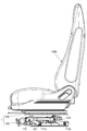
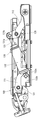
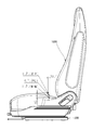
- FIG. 1 is a perspective view showing a suspension mechanism and a seat supported by the suspension mechanism according to an embodiment of the present invention.
- FIG. 2 is a front view of FIG.
- FIG. 3 is a side view of FIG.
- FIG. 4 is a cross-sectional view taken along line AA of FIG. 2 and shows a state where the movable support portion and the sheet support portion are positioned at the lower limit.
- FIG. 5 is a cross-sectional view taken along the line AA in FIG. 2 and shows a state in which the movable support portion and the sheet support portion are located at the upper limit.
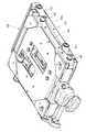
- FIG. 6 is a perspective view showing the first suspension unit.
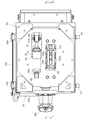
- FIG. 7 is a plan view of FIG.
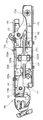
- FIG. 8 is a side view of FIG.
- FIG. 9 is a cross-sectional view taken along line BB in FIG. 10 is a cross-sectional view taken along the line CC of FIG.
- FIG. 11 is a perspective view showing the second suspension unit.
- FIG. 12 is a diagram showing the locus of the hip point (HP) of the seated person when only the first suspension part moves up and down.
- FIG. 13 is a diagram showing the locus of the hip point (HP) of the seated person when only the second suspension part moves up and down.
- FIG. 14 is a diagram showing the locus of the seated person's hip point (HP) when both the first suspension part and the second suspension part move up and down.
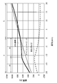
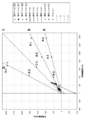
- FIG. 15 is a diagram showing an example of load-deflection characteristics of the spring mechanism, the torsion bar, and the magnetic spring.
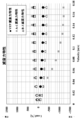
- FIG. 16 is a diagram showing the damping force characteristics of three dampers that can be employed as the first damper or the second damper.
- FIG. 17 shows the damping force of various dampers at a speed of 0.3 m / s.
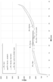
- FIG. 18 is a diagram showing the load-deflection characteristics of the first suspension unit using the “VEP” damper as the first damper.
- FIG. 19 is a diagram showing the load-deflection characteristics of the first suspension unit using the “B-3” damper as the first damper.
- FIG. 20 is a diagram illustrating a measurement result of the vibration transmissibility of the first suspension unit.
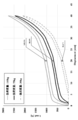
- FIG. 21 is a diagram showing the load-deflection characteristics of the second suspension part.
- FIG. 22 is a diagram showing the damping ratio of the second suspension unit.
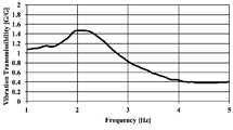
- FIG. 23 is a diagram showing the measurement result of the vibration transmissibility of the suspension mechanism when the vibration is applied with an amplitude of 32 mm (pp).
- FIGS. 1 to 14 show an example in which the suspension mechanism 1 according to one embodiment of the present invention is applied to support a vehicle seat 1000 such as a passenger car, a truck, a bus, and a forklift.
- the suspension mechanism 1 of the present embodiment includes a first suspension part 100 and a second suspension part 200.
- the first suspension unit 100 is supported by a movable support unit 140 that is supported to be movable up and down via a first link mechanism 110, a spring mechanism 120, and a damper 130 with respect to the fixed unit 101 that is integrally fixed to the vehicle body floor. It is equipped with.
- the first link mechanism 110 includes a pair of left and right front links 111 and 111 and a pair of left and right rear links 112 and 112.
- the front links 111 and 111 are pivotally supported so that the lower portions 111a and 111a are rotatable toward the front of the side edge portion 101a of the fixed portion 101, and the upper portions 111b and 111b are movable support portions 140 each having a substantially rectangular plate shape.
- the front frame 141 is connected.
- the rear links 112 and 112 are pivotally supported so that the lower portions 112a and 112a are rotatable toward the rear of the side edge portion 101a of the fixed portion 101, and the upper portions 112b and 112b are connected to the rear frame 142 of the movable support portion 140.
- the movable support part 140 can move up and down with respect to the fixed part 101.
- the first link mechanism 110 is a parallel link including the front links 111 and 111 and the rear links 112 and 112. Since it consists of a structure, it moves up and down along the rotation track of the front links 111 and 111 and the rear links 112 and 112. That is, along the rotation direction (direction A in FIG.
- the front frame 141 and the rear frame 142 are both made of a pipe material in the present embodiment, and torsion bars 121 and 121 are inserted therein (see FIGS. 9 and 10).
- the torsion bars 121 and 121 are linear springs that exhibit linear characteristics that change substantially linearly in load-deflection characteristics (see FIG. 15), and together with a magnetic spring 122 described later, 120 (referred to as “first spring mechanism”).
- first spring mechanism One ends of the torsion bars 121 and 121 are provided so as not to rotate relative to the front frame 141 and the rear frame 142, respectively, and the torsion bars 121 and 121 move the movable support part 140 relative to the fixed part 101.
- torsion bars 121 and 121 are connected to plate members 125c and 125d of the initial position adjusting member 125, respectively (see FIG. 7).
- the adjustment dial 125b When the adjustment dial 125b is rotated, the initial position adjustment member 125 rotates the adjustment shaft 125a, and the rotation rotates the plate member 125c connected to the torsion bar 121 on the front links 111 and 111 side. Furthermore, the plate member 125d connected to the torsion bar 121 on the side of the rear links 112 and 112 connected to the plate member 125c via the connecting plate 125e rotates. Therefore, when the adjustment dial 125b is rotated, the torsion bars 121 and 121 are twisted in either direction, and the initial elastic force of the torsion bars 121 and 121 is adjusted, so that the movable support portion 140 is adjusted regardless of the weight of the seated person. Can be adjusted to a predetermined position (for example, neutral position).
- a predetermined position for example, neutral position
- the linear spring that urges the movable support portion 140 in a direction that is relatively separated from the fixed portion 101 is not limited to the torsion bars 121 and 121, and a coil spring or the like can also be used.
- the rotation shaft portions of the front links 111 and 111 and the rear links 112 and 112 are provided as in this embodiment.
- Use of torsion bars 121 and 121 that can be incorporated is advantageous in terms of simplification of the structure, compactness, weight reduction, and the like.
- the magnetic spring 122 includes a fixed magnet unit 1220 and a movable magnet unit 1221 as shown in FIGS.
- the fixed magnet unit 1220 includes two fixed-side support frames 1220a and 1220a that are disposed at a predetermined interval along the width direction of the first suspension unit 100. Each of the fixed-side support frames 1220a and 1220a is fixed to the fixed portion 101, and fixed magnets 1220b and 1220b are attached to the fixed portions 101, respectively.
- the fixed magnets 1220b and 1220b facing each other at a predetermined interval are dipole magnets, each having a different polarity in the vertical direction and facing each other at a predetermined interval. , 1220a.
- the movable magnet unit 1221 includes a movable magnet 1221b disposed in the gap between the fixed magnets 1220b and 1220b that are disposed to face each other at a predetermined interval.
- the movable magnet 1221b is supported by a magnet mounting bracket 1221a that protrudes downward from the movable support portion 140.
- the movable support portion 140 moves up and down relatively with respect to the fixed portion 101, the movable magnet 1221b is moved together with the movable support portion 140.
- the gap between the fixed magnets 1220b and 1220b is moved up and down.
- the movable magnet 1221b is magnetized along this vertical movement direction.
- the spring characteristic exhibited when the movable magnet 1221b moves through the gap between the fixed magnets 1220b and 1220b varies depending on the relative position between the movable magnet 1221b and the fixed magnets 1220b and 1220b, and is shown in FIG.
- the load-deflection characteristic shows a non-linear characteristic. More specifically, the magnetic spring 122 separates the direction of action of the elastic force (restoring force) of the torsion bars 121 and 121, which are linear springs, that is, the movable support portion 140 from the fixed portion 101 in the load-deflection characteristic.
- a negative spring characteristic in which the restoring force in the direction decreases in a predetermined displacement range. That is, a negative spring in a predetermined vertical movement range (a range of U1 in the example of FIG. 15) in the vicinity of a position crossing the boundary between the N and S poles of two fixed magnets 1220b and 1220b adjacent to each other in the vertical direction. Demonstrate the characteristics.
- the first spring mechanism 120 of the present embodiment including the magnetic spring 122 and the torsion bars 121 and 121 described above has a range in which the negative spring characteristic of the magnetic spring 122 functions (in the example of FIG. In the range U1), the spring constant of the positive spring characteristic of the torsion bars 121, 121 (positive spring constant) and the spring constant of the negative spring characteristic range of the magnetic spring 122 (negative spring constant) are substantially the same.
- the first spring mechanism 120 in which both are superimposed has a constant load region in which the load load does not change even when the displacement amount increases, that is, the spring constant is substantially zero (preferably about ⁇ 10 N / mm to a range of about 10 N / mm).
- the central position of the movable magnet 1221b of the movable magnet unit 1221 is different at the neutral position of the vertical stroke of the movable support 140. It is preferable that the poles are set so as to substantially coincide with the boundary between two adjacent fixed magnets 1220b and 1220b.
- the magnetic spring 122 is installed in such a posture that the movable magnet 1221b moves in the vertical direction between the fixed magnets 1220b and 1220b (vertically placed).
- the fixed magnets 122b and 1220b are omitted from the fixed portion 101. It can also be set as the structure which installs with a horizontal attitude
- position horizontal placement
- the vertical space when the magnetic spring 122 is arranged can be made smaller than the vertical placement, and the suspension mechanism 1 can be made thinner, but the movement of the movable support part 140 in the vertical direction is movable magnet 1221b.
- a link mechanism for converting the movement into a substantially horizontal movement is required.
- FIG. 15 is a diagram showing the load-deflection characteristics of the torsion bars 121 and 121, the magnetic spring 122, and the first spring mechanism 120 used in the first suspension unit 100.
- the stroke of the seat suspension 1 of this embodiment is a maximum of 40 mm, and its neutral position is 20 mm.
- the characteristics shown with the neutral position set to zero are shown in FIG. 15.
- the range of the sign “ ⁇ ” is the range from the neutral position to the upper limit position
- the range of the sign “+” is the range from the neutral position to the lower limit position. Show.
- the magnetic spring 122 exhibits a negative spring characteristic in the range of about ⁇ 10 mm to about +10 mm.
- the former when the spring constant from about ⁇ 10 mm to 0 mm and the spring constant from 0 mm to about +10 mm are compared, the former is set with a larger spring constant, and the spring constant of the torsion bars 121 and 121 is superimposed.
- the constant load region is formed in a range from about ⁇ 10 mm to 0 mm.
- the range from 0 mm to about +10 mm is also a very low spring constant.
- the first damper 130 is a telescopic damper having a piston rod 131 and a cylinder 132 in which a piston attached to the piston rod 131 reciprocates.
- the end portion 131a of the piston rod 131 is pivotally supported by a mounting bracket 131b attached to a rear frame 142 that extends in the width direction toward the rear of the movable support portion 140.
- An end 132a of the cylinder 132 is pivotally supported by a mounting bracket 132b provided on the fixed portion 101 (see FIGS. 7 and 10).
- the first damper 130 for example, a relatively low damping force can be used as compared with the second damper 230 used in the second suspension unit 200. Thereby, since it can expand and contract more sensitively to minute vibrations, the suspension mechanism 1 having excellent vibration absorption characteristics can be obtained.
- the first damper 130 preferably has a damping force at a piston speed of 0.3 m / s of 500 N or less on both the expansion side and the contraction side, and more preferably in the range of 100 N to 500 N.
- an appropriate type such as an oil damper or a friction damper can be adopted.
- a linear member is wound around the outer periphery of a piston, and viscosity such as grease is wound around the linear member.
- a damper (“VEP” damper) having a structure in which both fluid damping force and viscous damping force function by attaching a fluid.
- FIG. 17 shows examples of damping force at 0.3 m / s in various dampers.
- the “VEP” damper and the “B-3” damper are the above-mentioned requirements of the first damper 130. Meet.
- a higher damping force can be used as the first damper 130.
- both the first suspension unit 100 and the second suspension unit 200 have a structure in which damping characteristics are emphasized. It is suitable for the suspension mechanism 1 that supports the driver's seat.
- the damper 130 absorbs an impact to a large-amplitude input in an earthworking machine.
- the damper 130 has an extension side damping force (speed 0.3 m / s) exceeding 500 N and an expansion side with respect to a contraction side damping force. Those having a characteristic that the damping force is 1.5 times or more is preferable.
- the damping force on the elongation side is in the range of 1000 to 1500 N at a speed of 0.3 m / s.
- dampers with symbols “B-1” and “A-1” are equivalent.
- the first damper 130 having such characteristics, more impact energy is absorbed during the upward operation of the movable support 140, and as a result, the force generated during the downward operation is reduced, and the downward operation is performed. The feeling of bottoming out can be suppressed.
- a damping force on the contraction side is 1000 N or more to absorb a large impact force ("D-1" and "D-2" dampers in Fig. 17), the feeling of bottoming will increase.
- the damping force is small during downward operation, and the impact can be mitigated by the elastic force of the spring mechanism 120 to suppress the feeling of bottoming.
- the second suspension unit 200 is supported by the movable support unit 140 of the first suspension unit 100 so as to be movable up and down via the second link mechanism 210, the spring mechanism 220, and the damper 230. (Refer to FIG. 4, FIG. 11, etc.).
- the cushion frame that supports the seat cushion portion 1100 of the seat 1000 constitutes the seat support portion 240, and includes side frames 241, 241, a front edge frame 242, a rear edge frame 243, and the like.
- the seat support portion 240 formed of a cushion frame is supported by the upper rail 252 of the slider 250, but the lower rail 251 is fixed to the movable support portion 140 via a mounting plate 143 (see FIG. 4). It moves up and down together with the movable support part 140.
- the sheet support portion 240 is supported by the upper rail 252 via the second link mechanism 210, as shown in FIGS.
- the second link mechanism 210 includes a pair of left and right front links 211 and 211, a pair of left and right rear links 212 and 212, and connecting links 213 and 213 that connect the front link 211 and the rear link 212 to each other on the left and right. It has.
- the front links 211 and 211 are formed in a substantially trapezoidal shape (see FIG. 14), and the upper portion near the front end is pivotally supported by the front bracket 252a of the upper rail 252 by the shaft member 211a, and the upper portion near the rear end is supported by the seat. Between the side frames 241 and 241 of the part 240, as shown in FIG. 11, it is connected to a front side reinforcing pipe 244 spanned behind the shaft member 211a in a plan view so as to be relatively rotatable.
- the rear links 212 and 212 are formed in a substantially triangular shape with the top portion on the lower side, and the upper portion near the front end is pivotally supported by the rear bracket 252b of the upper rail 252 by the shaft member 212a.
- the upper part in the vicinity of the rear end is connected between the side frames 241 and 241 of the seat support part 240 so as to be relatively rotatable with a rear side reinforcing pipe 245 spanned rearward from the shaft member 212a in plan view. Accordingly, the front links 211 and 211 and the rear links 212 and 212 of the second link mechanism 210 rotate about the shaft members 211a and 212a in the direction B in FIG.
- the movable support part 140 supported by the first link mechanism 110 of the first suspension 100 and the seat support part 240 supported by the second link mechanism 220 of the second suspension part 200 are shown in FIG.
- the operation direction viewed from the side surface when moving up and down is the reverse direction. Accordingly, when it is assumed that the seat 1000 is supported only by the first suspension unit 100 during the vertical movement, the locus of the vertical movement of the hip point (HP) of the seated person is shown in FIG.
- the locus becomes backward as it approaches the upper limit position and forward as it approaches the lower limit position.
- the trajectory of the vertical movement of (HP) becomes forward as it approaches the upper limit position, and becomes backward as it approaches the lower limit position.
- the locus of the seated person's hip point (H.P.) in the vertical movement in the suspension mechanism 1 of the present embodiment, in which both the first suspension part 100 and the second suspension part 200 are stacked is shown in FIG.
- it is a locus in a substantially vertical direction (“substantially vertical” is preferably a maximum displacement amount of 8 mm or less, more preferably 6 mm or less). Therefore, according to the suspension mechanism 1 of the present embodiment, the seated person is relatively vertically displaced with respect to the vertical vibration, and the displacement in the forward or backward direction is small, and the posture stability is high.
- the spring mechanism (hereinafter referred to as “second spring mechanism”) 220 of the second suspension unit 200 is composed of a linear spring exhibiting a linear characteristic that changes almost linearly in the load-deflection characteristic.
- the torsion bars 221 and 221 are inserted through the front-side reinforcing pipe 244 and the rear-side reinforcing pipe 245, respectively (see FIGS. 4 and 14).
- Each torsion bar 221, 221 has one end fixed to one side frame 241 and the other end penetrating the other side frame 241 to be a free end, and urges the seat support 240 upward. Arranged.
- a spring force for returning to the seating position is applied.
- a damper 230 having a small damping force is used as the first damper 130 of the first suspension unit 100
- a damper 230 having a relatively high damping force on the extension side is used.
- a high damping force can be used as the first damper 130
- a high damping force can be used as the second damper 230.
- the damping force on the expansion side is larger than the damping force on the contraction side, and more preferably, the damping force on the expansion side is more than 1.5 times that of the contraction side. This is also as described above.
- the second damper 230 engages the rear lower pipe 253 with the tip of the piston rod 231 engaged with the front reinforcing pipe 244 and the bottom of the cylinder 232 spanned between the upper rails 252 and 252 of the slider 250. They are engaged (see FIG. 11 etc.).
- the first suspension unit 100 and the second suspension unit 200 are set so that their vertical strokes are the same. Thereby, the position of the hip point of the person sitting on the seat 1000 as described above is stabilized. In this case, when applied to the driver's seat, it is more preferable to set the vertical stroke of the entire suspension mechanism 1 to be within 80 mm because the uncomfortable feeling during steering and operation is reduced.
- the first damper 130 is configured to employ a small damping force of 500 N or less, the vertical stroke of the first suspension unit 100 is longer than the vertical stroke of the second suspension unit 200. It can also be set. By extending the vertical stroke, the corresponding area of vibration absorption characteristics and shock absorption characteristics is widened.
- the maximum length is within twice the vertical stroke of the second suspension unit 200 (for example, when the vertical stroke of the second suspension unit 200 is 40 mm,
- the vertical stroke of the suspension unit 100 is preferably within 80 mm, and the vertical stroke is adjusted by adjusting the lengths of the first link mechanism 110 and the second link mechanism 210, the lengths of the dampers 130 and 230, and the expansion and contraction. It can be performed by adjusting the amount, adjusting the mounting angle, or the like.
- the first damper 130 when a small damper having a damping force of 500 N or less is adopted as the first damper 130, the first damper 130 expands and contracts with respect to vibration in the normal region input through the vehicle body floor. Therefore, the elastic force of the first spring mechanism 120 acts effectively, and vibration can be effectively absorbed by the vertical movement of the first suspension unit 100.
- the first spring mechanism 120 includes a combination of the torsion bars 121 and 121 having positive spring characteristics and the magnetic spring 122 having negative spring characteristics, and has a certain displacement range (usually , Set near the neutral position of the first suspension unit 100) has a constant load region where the superimposed spring constant is substantially zero. Therefore, vibration absorption characteristics are higher. Further, since the damping force of the first damper 130 is small, the reciprocating motion of the piston in the cylinder 132 is smoothly performed even with slight vibration, and the energy absorption capability is high.
- the first damper 130 of the first suspension unit 100 cannot exhibit a damping force corresponding to the first damper 130, but the second damper 230. Therefore, the damping force of the second suspension unit 200 acts greatly. Therefore, in this embodiment, impact vibration can also be efficiently absorbed.
- the first damper 130 of the first suspension unit 100 having a high damping force is used as in the case of the second damper 230, a high damping effect is provided for impact vibration with a large amplitude. Can be demonstrated.
- the characteristics of the first suspension unit 100 alone using a first damper 130 having a small damping force were examined. At that time, the test was performed with the movement of the second link mechanism 210 of the second suspension unit 200 fixed. The characteristics of the spring mechanism 120 used, and the torsion bars 121 and 121 and the magnetic spring 122 constituting the spring mechanism 120 were as shown in FIG.
- the first damper 130 is composed of a damper (symbol “VEP” in FIGS. 16 and 17) and an oil damper (in FIGS.
- FIGS. 18 and 19 show the load-deflection characteristics of the suspension mechanism 1 installed so that the first suspension part 100 is movable and the second suspension part 200 is not functioning.
- the pressurizer is operated at a speed of 50 mm / min, and the load mass at the neutral position (the one using the “VEP” damper is 20 mm in relation to the maximum stroke of the “VEP” damper used, the other is 25 mm).
- the load mass at the neutral position (the one using the “VEP” damper is 20 mm in relation to the maximum stroke of the “VEP” damper used, the other is 25 mm).
- the load mass at the neutral position the one using the “VEP” damper is 20 mm in relation to the maximum stroke of the “VEP” damper used, the other is 25 mm.
- the one using the “VEP” damper had a vibration transmissibility of 1.1 or less at a resonance point of about 2 Hz.
- the vibration transmissibility further decreased in the high frequency region from the resonance point, and the vibration transmissibility at 4 Hz for load masses of 78 kg and 98 kg was 0.6 or less.
- the vibration transmissibility is 1.2 or less near the resonance point of 3 Hz, and the vibration transmissibility in the high frequency region is gradually lower than the resonance point.
- the vibration transmissibility at 4 Hz for 78 kg and 98 kg was 0.8 or less.
- the static spring constant k0 25000 N / m near the neutral position (equilibrium) (17.5-22.5 mm in the loading process), and the hysteresis loss at the neutral position was 88.8 N. It was.
- the static spring constant k4 309000 N / m of 1.2 to 2.2 mm in the loading process
- the static spring constant k3 15900 N / m of 10 to 15 mm
- the static spring constant k1 43800 N / m of 25 to 30 mm m
- a static spring constant k2 of 35 to 40 mm 16,000 N / m.
- FIG. 22 shows the damping ratio of the second suspension unit 200 obtained by calculation using the dynamic spring constant obtained from the static load characteristic of the load mass of 75 kg and the damping force of 0.3 m / s. .
- the damping ratio is 0.15 or less on the contraction side, but the extension side is larger than that, and in particular, the damping ratio after the neutral position when the seat support 240 is raised. Is about 0.4 to 0.5, and it can be seen that it has high attenuation characteristics.
- the attenuation ratio of “Magneto-SUS” shown in FIG. 22 is data when the damper of “A-1” is used as the first damper 130 in the first suspension unit 100, and in this case as well.
- damping ratio is obtained on the elongation side.
- “Rubber-SUS” is data of a suspension having a structure in which a torsion bar 121 is removed from the first suspension unit 100 and a rubber is attached to a position where the movable support unit 140 and the fixed unit 101 face each other.
- the damping ratio on the extension side of the damper was low and constant at around 0.15.
- the “B-3” damper is used as the first damper 130
- the “A-1” damper is used as the second damper 230.
- a vibration experiment was performed on the suspension mechanism 1. Specifically, the seat 1000 having the suspension mechanism 1 is set in a vibration exciter, and a SEAT value (Seat Effective Amplitude Transmissibility factor) is obtained based on JIS A 8304: 2001 (ISO 7096: 2000). It was.
- the first damper 130 remains “B-3” and the second damper 230 adopts the damper “B-1” in FIG. 17 (extension-side damping force 1370N, contraction-side damping force 760N).
- the average SEAT value was 0.74, which did not satisfy the standard.
- the damper (A-2) in FIG. 17 extension-side damping force 900N, contraction-side damping force 250N
- the damper (A-1) is used as the second damper 230.
- the same test was carried out with the same subject for each of the cases of adopting “B-1” and the “B-1” damper. The average values of the SEAT values were all 0.77 and did not satisfy the standard.
- the seat 1000 provided with the suspension mechanism 1 was set on a vibration exciter and a vibration experiment was performed.
- the SEAT value (Seat Effective Amplitude Transmissibility factor) was determined based on JIS A 8304: 2001 (ISO 7096: 2000).
- Subject with input spectrum class EM6 (excitation center frequency: 7.6 Hz, maximum PSD value: 0.34 (m / s 2 ) 2 / Hz), which is the standard for “crawler tractor dozers of 50,000 kg or less”, and a body weight of 99 kg Sat down and tested.
- EM6 excitation center frequency: 7.6 Hz
- maximum PSD value 0.34 (m / s 2 ) 2 / Hz)
- the average value of the obtained SEAT values was 0.56. Since the standard of SEAT value of EM6 was less than 0.7, the standard was satisfied.
- the input spectrum class EM8 (excitation center frequency: 3.3 Hz, PSD maximum value: 0.4 (m / s 2 ) 2 / Hz), which is the standard of “a compact loader of 4,500 kg or less”, has the same weight as above.
- the SEAT value was 0.76. Since the standard of SEAT value of EM8 was less than 0.8, the standard was satisfied.
Landscapes
- Engineering & Computer Science (AREA)
- Aviation & Aerospace Engineering (AREA)
- Transportation (AREA)
- Mechanical Engineering (AREA)
- Seats For Vehicles (AREA)
Abstract
入力振動に対する着座者の姿勢安定性を向上させることができると共に、振動吸収特性、あるいは、衝撃性振動による衝撃吸収特性を従来と比較してより向上させる。可動支持部(140)及びシート支持部(240)をそれぞれリンク機構(110,210)を介して支持した2つのサスペンション部(100,200)を上下2段に配置した構造であると共に、可動支持部(140)及びシート支持部(240)が入力振動に応じて相対的に上下動する際、それぞれを支持する2つのリンク機構(110,210)が互いに逆方向に回転動作する構成である。そのため、シート支持部(240)に支持されるシートに着座した人のヒップポイントの位置が、垂直に近い軌跡で変位することになり、リンク機構が1つの場合と比較して前後揺動が減少し、着座姿勢が安定し、乗り心地がよくなる。
Description
本発明は、乗物のシートの支持に適するサスペンション機構に関する。
特許文献1,2には、下部フレームに対して上下動可能に設けられる上部フレームを磁気ばねとトーションバーとにより弾性的に支持したシートサスペンションが開示されている。トーションバーの復元力の作用方向と同方向の復元力が変位量の増加に伴って増加する特性を「正のばね特性(その時のばね定数を「正のばね定数」)」とし、トーションバーの復元力の作用方向と同方向の復元力が変位量の増加に拘わらず減少する特性を「負のばね特性(その時のばね定数を「負のばね定数」)」とした場合に、所定の変位範囲において磁気ばねが負のばね特性を示すことを利用して、正のばね特性を示すトーションバーとの組み合わせによって、所定の変位範囲における両者を重畳した系全体の変位量に対する荷重値が略一定となる定荷重領域(ばね定数を略ゼロとなる領域)の特性を有するサスペンションが開示されている。
特許文献1,2のサスペンションは、所定の周波数及び振幅の通常振動に対しては、上記の磁気ばねとトーションバーを用いた構成により、両者を重畳したばね定数が略ゼロになる定荷重領域でこれらの振動を吸収し、衝撃性振動によるエネルギーは上部フレーム及び下部フレーム間に掛け渡したダンパーによって吸収する構成となっている。
従って、特許文献1,2のサスペンションは優れた振動吸収特性、衝撃吸収特性を発揮するが、いずれも平行リンク構造を採用しているため、上下動に伴って着座者のヒップポイントが前後に変位し、着座姿勢の安定性の点で改善の余地がある。また、土工機械の運転席などにおいては、大きな凹凸のある路面を走行する機会が多いため、振幅のより大きな衝撃性振動に対する対策の向上が重視されている。
本発明は、上記の点に鑑みなされたものであり、入力振動に対する着座者の姿勢安定性を向上させることができると共に、振動吸収特性、あるいは、衝撃性振動による衝撃吸収特性を従来と比較してより向上させることができるサスペンション機構を提供することを課題する。
上記課題を解決するため、本発明のサスペンション機構は、固定部に対して、第1のリンク機構、ばね機構及びダンパーを介して上下動可能に支持される可動支持部を備えてなる第1のサスペンション部と、
前記第1のサスペンション部の上方に配置され、前記可動支持部に対して、第2のリンク機構、ばね機構及びダンパーを介して上下動可能に支持されるシート支持部を備えてなる第2のサスペンション部と
を有し、
前記第1のリンク機構及び前記第2のリンク機構の回転方向が、それぞれの回転中心を基準として前後に逆方向となるように設定されていることを特徴とする。
前記第1のサスペンション部の上方に配置され、前記可動支持部に対して、第2のリンク機構、ばね機構及びダンパーを介して上下動可能に支持されるシート支持部を備えてなる第2のサスペンション部と
を有し、
前記第1のリンク機構及び前記第2のリンク機構の回転方向が、それぞれの回転中心を基準として前後に逆方向となるように設定されていることを特徴とする。
前記各ダンパーとして、いずれも伸び側の減衰力が縮み側の減衰力よりも高いものが用いられていることが好ましい。前記各ダンパーとして、伸び側又は縮み側の少なくとも一方の減衰力が異なるものが用いられていることが好ましい。
前記第1のサスペンション部又は前記第2のサスペンション部の一方のばね機構は、線形特性を示す線形ばねと、固定磁石と、前記中間フレーム又は前記上部フレームの相対動作に伴って前記固定磁石との相対位置が変位する可動磁石とを備え、前記固定磁石と前記可動磁石の相対位置に応じてばね定数が変化する非線形特性を示す磁気ばねとを有してなり、所定の変位範囲においてばね定数が略ゼロとなる特性を備えていることが好ましい。
前記第1のサスペンション部又は前記第2のサスペンション部の他方のばね機構は、線形特性を示す線形ばねから構成されることが好ましい。
なお、前記線形ばねとしては、トーションバーが好ましい。
前記第1のサスペンション部又は前記第2のサスペンション部の他方のばね機構は、線形特性を示す線形ばねから構成されることが好ましい。
なお、前記線形ばねとしては、トーションバーが好ましい。
前記第1のサスペンション部の上下ストロークと前記第2のサスペンション部の上下ストロークとが同一であることが好ましい。
また、本発明のサスペンション機構は、土工機械の運転席のシートの支持に適している。
また、本発明のサスペンション機構は、土工機械の運転席のシートの支持に適している。
本発明では、可動支持部及びシート支持部をそれぞれリンク機構を介して支持した2つのサスペンション部を上下2段に配置した構造であると共に、可動支持部及びシート支持部が入力振動に応じて相対的に上下動する際、それぞれを支持する2つのリンク機構が互いに逆方向に回転動作する構成である。そのため、シート支持部に支持されるシートに着座した人のヒップポイントの位置が、垂直に近い軌跡で変位することになり、リンク機構が1つの場合と比較して前後揺動が減少し、着座姿勢が安定し、乗り心地がよくなる。
また、2つのサスペンション部を用いているため、それぞれにおいて異なる減衰特性のダンパーを採用することにより、サスペンション部が一段の従来の構造と比較し、減衰力がより高い特性の構成としたり、減衰力の小さいものを組み合わせて、微振動に対する振動吸収特性を高めた構成としたり、本発明のサスペンション機構を用いる対象(乗用車、土工機械等)に合わせた特性に設定することが容易である。例えば、上下のサスペンション部のいずれにも減衰力が所定以上のものを採用することで、高い衝撃吸収特性が得られ、凹凸のある路面を走行することの多い土工機械の運転席用に適した構成とすることも容易である。
以下、図面に示した実施形態に基づき本発明をさらに詳細に説明する。図1~図14は、本発明の一の実施形態に係るサスペンション機構1を、乗用車、トラック、バス、フォークリフト等の乗物用のシート1000の支持に適用した例を示したものである。これらの図に示したように、本実施形態のサスペンション機構1は、第1のサスペンション部100と第2のサスペンション部200とを有してなる。
第1のサスペンション部100は、車体フロアに一体に固定された固定部101に対して、第1のリンク機構110、ばね機構120及びダンパー130を介して上下動可能に支持される可動支持部140を備えてなる。第1のリンク機構110は、左右一対の前部リンク111,111と、左右一対の後部リンク112,112とを有してなる。前部リンク111,111は、各下部111a,111aが、固定部101の側縁部101aの前方寄りに回転可能に軸支され、各上部111b,111bが、略方形板状の可動支持部140の前部フレーム141に連結されている。後部リンク112,112は、各下部112a,112aが、固定部101の側縁部101aの後方寄りに回転可能に軸支され、各上部112b,112bが、可動支持部140の後部フレーム142に連結されている。これにより、可動支持部140は、固定部101に対して上下動可能に、より正確には、第1のリンク機構110が前部リンク111,111と後部リンク112,112とを備えた平行リンク構造からなるため、前部リンク111,111及び後部リンク112,112の回転軌道に沿って上下動する。すなわち、各下部111a,111a,112a,112aを回転中心とする前部リンク111,111及び後部リンク112,112の回転方向(図14のA方向)に沿って、つまり、前部リンク111,111及び後部リンク112,112が前方に倒れて下限位置に向かう方向とその反対に戻って上限位置に向かう方向に沿って変位し、可動支持部140は上下動する。
前部フレーム141及び後部フレーム142は、本実施形態ではいずれもパイプ材から形成され、それぞれ、トーションバー121,121が挿入されている(図9,図10参照)。本実施形態では、このトーションバー121,121が、荷重-たわみ特性においてほぼ線形に近い変化となる線形特性を示す線形ばねであり(図15参照)、後述する磁気ばね122と共にばね機構(以下、「第1のばね機構」という)120を構成する。トーションバー121,121の一端は、前部フレーム141及び後部フレーム142に対してそれぞれ相対回転しないように設けられ、トーションバー121,121は、可動支持部140を固定部101に対して相対的に離間させる方向、すなわち、上方向に付勢する弾性力を発揮するように設定される。トーションバー121,121の他端は、初期位置調整部材125のプレート部材125c,125dにそれぞれ接続されている(図7参照)。
初期位置調整部材125は、調整用ダイヤル125bを回転させると、それによって調整用シャフト125aが回転し、その回転によって、前部リンク111,111側のトーションバー121に接続されたプレート部材125cが回転し、さらに、このプレート部材125cに連結版125eを介して連結された後部リンク112,112側のトーションバー121に接続されたプレート部材125dが回転する。従って、調整用ダイヤル125bを回転操作すると、トーションバー121,121がいずれかの方向にねじられ、トーションバー121,121の初期弾性力が調整され、着座者の体重にかかわらず、可動支持部140を所定の位置(例えば中立位置)に調整できるようになっている。また、可動支持部140を固定部101に対して相対的に離間する方向に付勢する線形ばねとしては、トーションバー121,121に限らず、コイルスプリング等を用いることも可能である。但し、可動支持部140のストロークが短い範囲で線形性の高い正のばね定数を得るためには、本実施形態のように、前部リンク111,111及び後部リンク112,112の回転軸部に組み込むことができるトーションバー121,121を用いることが構造の簡易化、コンパクト化、軽量化等の点で有利である。
磁気ばね122は、図7及び図9に示したように、固定マグネットユニット1220と可動マグネットユニット1221とを備えてなる。固定マグネットユニット1220は、第1のサスペンション部100の幅方向に沿って所定間隔をおいて配設される2つの固定側支持フレーム1220a,1220aを有している。各固定側支持フレーム1220a,1220aは、固定部101に固定され、それぞれに固定磁石1220b,1220bが取り付けられている。所定間隔をおいて対向する固定磁石1220b,1220bは、二極磁石が用いられ、それぞれ垂直方向に異極が隣接し、所定間隔を隔てて同極同士が対面する姿勢で各固定側支持フレーム1220a,1220aに取り付けられる。
可動マグネットユニット1221は、所定間隔をおいて対向配置される固定磁石1220b,1220bの間隙に配置される可動磁石1221bを備えてなる。可動磁石1221bは、可動支持部140から下方に突出させた磁石取り付けブラケット1221aによって支持されており、可動支持部140が固定部101に対して相対的に上下動すると、該可動支持部140と共に、固定磁石1220b,1220b間の間隙を上下動する。可動磁石1221bは、この上下動方向に沿って着磁されている。
磁気ばね122は、可動磁石1221bが固定磁石1220b,1220bの間隙を移動することにより発揮されるばね特性が、可動磁石1221bと固定磁石1220b,1220bとの相対位置によって変化し、図15に示したように、荷重-たわみ特性が非線形特性を示す。より具体的には、磁気ばね122は、荷重-たわみ特性において、線形ばねであるトーションバー121,121の弾性力(復元力)の作用方向すなわち可動支持部140を固定部101に対して離間させる方向に復元力が増加する特性を正のばね特性とした場合に、所定の変位量範囲では、当該方向への復元力が減少する負のばね特性を示す。すなわち、異極同士が垂直方向に隣接する2つの固定磁石1220b,1220bのN,S極の境界を横切る位置付近の所定の上下動範囲(図15の例では符号U1の範囲)において負のばね特性を発揮する。
この結果、磁気ばね122と上記したトーションバー121,121とを備えてなる本実施形態の第1のばね機構120は、磁気ばね122における負のばね特性が機能する範囲(図15の例では符号U1の範囲)においては、トーションバー121,121の正のばね特性のばね定数(正のばね定数)と磁気ばね122の負のばね特性範囲のばね定数(負のばね定数)とがほぼ同じになるように調整することで、両者を重畳した第1のばね機構120全体として、変位量が増加しても負荷荷重が変化しない定荷重領域すなわちばね定数が略ゼロ(好ましくは、約-10N/mm~約10N/mmの範囲)になる領域を有することになる。このばね定数が実質的に略ゼロになる領域をできるだけ有効利用するためには、可動支持部140の上下方向ストロークの中立位置において、可動マグネットユニット1221の可動磁石1221bは、その中央位置が、異極同士が隣接する2つの固定磁石1220b,1220bの境界に略一致するようにセットされることが好ましい。
なお、本実施形態では磁気ばね122を、可動磁石1221bが固定磁石1220b,1220b間を上下方向に移動する姿勢(縦置き)で設置しているが、固定磁石122b,1220bを固定部101に略水平姿勢(横置き)で設置し、可動磁石1221bを略水平方向に移動させる構成とすることもできる。横置きにした場合には、磁気ばね122を配置した際の上下方向スペースを縦置きよりも小さくでき、サスペンション機構1をより薄型にしやすいものの、可動支持部140の上下方向の動きを可動磁石1221bの略水平方向の動きに変換するためのリンク機構が必要となる。このため、可動磁石1221bを動作させる際に、そのリンク機構の動きに伴う摩擦減衰が生じ、動的ばね定数の増加に影響する。これに対し、本実施形態のような縦置きにした場合、可動磁石1221bを可動支持部140に固定するだけで支持でき、リンク機構を設けることに伴う摩擦減衰の影響がない。
ここで図15は、第1のサスペンション部100で用いたトーションバー121,121、磁気ばね122及び第1のばね機構120の荷重-たわみ特性を示した図である。本実施形態のシートサスペンション1のストロークは最大40mmであり、その中立位置が20mmである。中立位置をゼロに設定して示した特性が図15であり、符号「-」の範囲が中立位置から上限位置までの範囲で、符号「+」の範囲が中立位置から下限位置までの範囲を示す。この図に示したように、本実施形態では、約-10mmから約+10mmの範囲において、磁気ばね122が負のばね特性を示している。本実施形態ではさらに約-10mmから0mmまでのばね定数と、0mmから約+10mmまでのばね定数とを比較すると前者の方が大きなばね定数で設定され、トーションバー121,121のばね定数と重畳すると、約-10mmから0mmまでの範囲で定荷重領域が形成されている。また、0mmから約+10mmまでの範囲も極めて低いばね定数となっている。
次に、第1のサスペンション部100で用いられるダンパー(第1のダンパー)130について説明する。第1のダンパー130は、ピストンロッド131と、このピストンロッド131に取り付けられたピストンが内部を往復動作するシリンダ132とを有する伸縮式ダンパーである。ピストンロッド131の端部131aは、可動支持部140の後方寄りに幅方向に掛け渡された後部フレーム142に取り付けた取り付けブラケット131bに軸支されている。シリンダ132の端部132aは、固定部101に設けた取り付けブラケット132bに軸支されている(図7,図10参照)。これにより、可動支持部140が固定部101に対して上下動すると、第1のダンパー130も伸縮動作する。
第1のダンパー130としては、例えば、第2のサスペンション部200で用いられる第2のダンパー230との比較で、相対的に減衰力の低いものを用いることができる。これにより、微振動に対してもより敏感に伸縮動作できるため、振動吸収特性に優れたサスペンション機構1とすることができる。この場合、第1のダンパー130は、ピストンスピード0.3m/sでの減衰力が、伸び側及び縮み側のいずれも500N以下のものが好ましく、100N~500Nの範囲のものがより好ましい。第1のダンパー130は、減衰力がこのように低いいものであれば、オイルダンパー、摩擦ダンパー等適宜の種類のものを採用できる。また、本願の一部の発明者が加わってなされた発明である特願2016-153526号において提案されているダンパーで、ピストンの外周に線状部材を巻き付け、この線状部材にグリース等の粘性流体を付着させ、摩擦減衰力と粘性減衰力との両者が機能する構造のダンパー(「VEP」ダンパー)を採用することもできる。図17は、各種ダンパーにおける0.3m/sでの減衰力の例を示したものであるが、このうち、「VEP」ダンパー、「B-3」ダンパーが、第1のダンパー130の上記要件を満たしている。
その一方、第1のダンパー130として、より減衰力の高いものを用いることもできる。この場合、後述の第2のダンパー230としても減衰力の高いものを用いることで、第1のサスペンション部100及び第2のサスペンション部200のいずれもが減衰特性を重視した構造となり、土工機械の運転席を支持するサスペンション機構1に適している。土工機械における大振幅の入力に対する衝撃を吸収するものとしては、ダンパー130は、伸び側の減衰力(速度0.3m/s)が500Nを超え、かつ、縮み側の減衰力に対して伸び側の減衰力が1.5倍以上の特性を有するものが好ましい。より好ましくは、伸び側の減衰力が速度0.3m/sで1000~1500Nの範囲のものである。例えば、図17において、「B-1」、「A-1」の記号のダンパーが相当する。このような特性を有する第1のダンパー130を用いることにより、可動支持部140の上方向動作時において衝撃エネルギーがより多く吸収され、その結果として下方向動作時に生じる力が小さくなり、下方向動作時の底付き感を抑制できる。大きな衝撃力を吸収しようとして、縮み側の減衰力が1000N以上のものを採用した場合(図17の「D-1」、「D-2」のダンパー)、底付き感が大きくなるが、上記のような条件の第1のダンパー230を採用することにより、下方向動作時には、減衰力が小さく、ばね機構120の弾性力により衝撃を緩和して底付き感を抑制できる。
次に、第2のサスペンション部200について説明する。第2のサスペンション部200は、第1のサスペンション部100の可動支持部140に対して、第2のリンク機構210、ばね機構220及びダンパー230を介して上下動可能に支持されるシート支持部240を備えてなる(図4,図11等参照)。
本実施形態では、シート1000のシートクッション部1100を支持するクッションフレームがシート支持部240を構成しており、サイドフレーム241,241、前縁フレーム242、後縁フレーム243等を有している。クッションフレームからなるシート支持部240は、スライダ250のアッパーレール252に支持されるが、ロアレール251が可動支持部140に取り付け板143を介して固定されており(図4参照)、スライダ250は、可動支持部140と共に上下動する。
シート支持部240は、図11及び図14に示したように、アッパーレール252に、第2のリンク機構210を介して支持される。第2のリンク機構210は、左右一対の前部リンク211,211と、左右一対の後部リンク212,212と、左右それぞれにおいて、前部リンク211及び後部リンク212同士を連結する連結リンク213,213とを有してなる。
前部リンク211,211は、略台形に形成され(図14参照)、前端付近の上部が、アッパーレール252の前部ブラケット252aに軸部材211aにより軸支され、後端付近の上部がシート支持部240のサイドフレーム241,241間において、図11に示したように平面視で軸部材211aより後方に掛け渡した前部側補強パイプ244に相対回転可能に連結されている。
後部リンク212,212は、図11及び図14に示したように頂部を下側とした略三角形に形成され、前端付近の上部が、アッパーレール252の後部ブラケット252bに軸部材212aにより軸支され、後端付近の上部がシート支持部240のサイドフレーム241,241間において、平面視で軸部材212aより後方に掛け渡した後部側補強パイプ245に相対回転可能に連結されている。従って、第2のリンク機構210の前部リンク211,211及び後部リンク212,212は、それぞれ軸部材211a,212aを回転中心として図14のB方向に回転し、シート支持部240はその回転軌道に沿って、上限位置と下限位置との間を上下動する。すなわち、第1のサスペンション100の第1のリンク機構110によって支持される可動支持部140と、第2サスペンション部200の第2のリンク機構220によって支持されるシート支持部240とは、図14の矢印A方向、B方向で示したように、上下動する際の側面から見た動作方向が前後に逆方向となる。従って、上下動時において、第1のサスペンション部100のみによってシート1000が支持されていると仮定した場合には、着座者のヒップポイント(H.P.)の上下動の軌跡は図12に示したとおり、上限位置に近づくほど後方になり、下限位置に近づくほど前方になる軌跡となり、第2のサスペンション部200のみによってシート1000が支持されていると仮定した場合には、着座者のヒップポイント(H.P.)の上下動の軌跡は、図13に示したとおり、上限位置に近づくほど前方になり、下限位置に近づくほど後方になる。この結果、第1サスペンション部100及び第2サスペンション部200が積層された両者を合わせた本実施形態のサスペンション機構1における着座者のヒップポイント(H.P.)の上下動時の軌跡は、図14に示したとおり、ほぼ垂直方向(「ほぼ垂直」とは、好ましくは、前後への最大変位量が8mm以下、より好ましくは6mm以下である)の軌跡となる。よって、本実施形態のサスペンション機構1によれば、上下振動に対して、着座者はほぼ垂直に相対変位し、前方又は後方への変位が少なく、姿勢の安定性が高い。
第2のサスペンション部200のばね機構(以下、「第2のばね機構」という)220は、荷重-たわみ特性においてほぼ線形に近い変化となる線形特性を示す線形ばねから構成される。具体的には、前部側補強パイプ244及び後部側補強パイプ245にそれぞれ挿通されたトーションバー221,221から構成される(図4,図14等参照)。各トーションバー221,221は、一端が一方のサイドフレーム241に固定され、他端が他方のサイドフレーム241を貫通して自由端となっており、シート支持部240を上方に付勢するように配設される。これにより、人が着座した状態で、シート支持部240が相対的に下方に変位した際には、着座位置に復帰させようとするばね力が働く。
ダンパー230は、上記のように、第1のサスペンション部100の第1のダンパー130として、減衰力の小さいものを採用した場合には、相対的に伸び側の減衰力が高いものが用いられる。また、第1のダンパー130として減衰力の高いものを用い、さらに第2のダンパー230としても減衰力の高いものを用いることができることも上記のとおりである。これにより、より大きな衝撃性振動に対応できる構成とすることができる。但し、いずれの場合も、伸び側の減衰力が縮み側の減衰力より大きなものが好ましく、さらには、縮み側に対して伸び側の減衰力が1.5倍以上の特性を有するものが好ましいことも上記のとおりである。
なお、第2のダンパー230は、ピストンロッド231の先端を前部側補強パイプ244に係合させ、シリンダ232の底部をスライダ250のアッパーレール252,252間に掛け渡した後部側下部パイプ253に係合させて配置している(図11等参照)。
ここで、第1のサスペンション部100と第2のサスペンション部200は、上下ストロークがそれぞれ同一となるように設定することが好ましい。それにより、上記のようにシート1000に着座している人のヒップポイントの位置が安定する。この場合、運転席に適用した場合、その操縦、操作中の違和感が少なくなることから、サスペンション機構1全体の上下ストロークとして80mm以内となるように設定することがより好ましい。その一方、第1のダンパー130として、減衰力が500N以下の小さなものを採用した構成とした場合には、第1のサスペンション部100の上下ストロークを、第2のサスペンション部200の上下ストロークより長い設定とすることもできる。上下ストロークを長くすることで振動吸収特性、衝撃吸収特性の対応領域が広くなる。但し、あまり長くすると着座時の違和感にもつながるので、最長でも第2のサスペンション部200の上下ストロークの2倍以内(例えば、第2のサスペンション部200の上下ストロークを40mmとした場合、第1のサスペンション部100の上下ストロークは80mm以内とすることが好ましい。なお、上下ストロークの調整は、第1のリンク機構110及び第2のリンク機構210の長さの調整、ダンパー130,230の長さや伸縮量の調整、取り付け角度の調整等により行うことができる。
本実施形態によれば、第1のダンパー130として減衰力500N以下の小さなものを採用した場合、車体フロアを介して入力される通常領域の振動に対しては、第1のダンパー130が伸縮動作しやすいため、第1のばね機構120の弾性力が有効に作用し、第1のサスペンション部100の上下動によって効果的に振動吸収することができる。特に、本実施形態によれば、第1のばね機構120が正のばね特性を備えたトーションバー121,121と負のばね特性を備えた磁気ばね122との組み合わせからなり、ある変位範囲(通常、第1のサスペンション部100の中立位置付近に設定)においては重畳したばね定数が略ゼロとなる定荷重領域を有している。そのため、振動吸収特性はより高い。また、第1のダンパー130の減衰力が小さいため、微振動でもシリンダ132内のピストンの往復運動が円滑に行われ、エネルギー吸収能力も高い。
また、路面の大きな凹凸等により、振幅の大きな衝撃性振動が入力された場合には、第1のサスペンション部100の第1のダンパー130ではそれに見合う減衰力を発揮できないが、第2のダンパー230が伸縮動作するため、第2のサスペンション部200の減衰力が大きく作用する。そのため、本実施形態では、衝撃性振動も効率よく吸収することができる。
その一方、第1のサスペンション部100の第1のダンパー130としても、第2のダンパー230と同様に減衰力の高いものを採用した場合には、振幅の大きな衝撃性振動に対して高い減衰効果を発揮できる。
その一方、第1のサスペンション部100の第1のダンパー130としても、第2のダンパー230と同様に減衰力の高いものを採用した場合には、振幅の大きな衝撃性振動に対して高い減衰効果を発揮できる。
(減衰力の小さい第1のダンパー130を取り付けた第1のサスペンション部100の特性)
第1のダンパー130として減衰力の小さなものを採用した第1のサスペンション部100単体の特性を調べた。その際、第2のサスペンション部200の第2のリンク機構210の動きを固定して試験を行った。使用したばね機構120、並びにばね機構120を構成するトーションバー121,121及び磁気ばね122の特性は、図15に示したとおりであった。第1のダンパー130は、上記のピストンに線状部材を巻き付けた摩擦減衰力と粘性減衰力が作用するダンパー(図16及び図17の記号「VEP」)とオイルダンパー(図16及び図17の記号「B-3」、0.3m/sの伸び側減衰力400N、縮み側減衰力200N)をそれぞれ取り付けて測定した。
第1のダンパー130として減衰力の小さなものを採用した第1のサスペンション部100単体の特性を調べた。その際、第2のサスペンション部200の第2のリンク機構210の動きを固定して試験を行った。使用したばね機構120、並びにばね機構120を構成するトーションバー121,121及び磁気ばね122の特性は、図15に示したとおりであった。第1のダンパー130は、上記のピストンに線状部材を巻き付けた摩擦減衰力と粘性減衰力が作用するダンパー(図16及び図17の記号「VEP」)とオイルダンパー(図16及び図17の記号「B-3」、0.3m/sの伸び側減衰力400N、縮み側減衰力200N)をそれぞれ取り付けて測定した。
・静荷重特性
図18及び図19は、上記の第1のサスペンション部100を可動にし、第2のサスペンション部200を機能しないように設置したサスペンション機構1の荷重-たわみ特性を示す。いずれも、加圧具を50mm/minの速度で動作させ、中立位置(「VEP」ダンパーを用いたものは、使用した「VEP」ダンパーの最大ストロークの関係で20mm、その他は25mm)における負荷質量が加荷工程において1250Nとなるように設定して測定した。中立位置を中心とした±5mmの範囲の加荷工程におけるばね定数k1、加荷工程において中立位置から10mm下方に変位した位置を中心とした±2.5mmの範囲のばね定数k2、中立位置のヒステリシスロスは、それぞれ各図に示したとおりであった。
図18及び図19は、上記の第1のサスペンション部100を可動にし、第2のサスペンション部200を機能しないように設置したサスペンション機構1の荷重-たわみ特性を示す。いずれも、加圧具を50mm/minの速度で動作させ、中立位置(「VEP」ダンパーを用いたものは、使用した「VEP」ダンパーの最大ストロークの関係で20mm、その他は25mm)における負荷質量が加荷工程において1250Nとなるように設定して測定した。中立位置を中心とした±5mmの範囲の加荷工程におけるばね定数k1、加荷工程において中立位置から10mm下方に変位した位置を中心とした±2.5mmの範囲のばね定数k2、中立位置のヒステリシスロスは、それぞれ各図に示したとおりであった。
・振動実験
第1のサスペンション部100のシート1000を含めた負荷質量が50kg、78kg、98kgとなるように錘を載せて調整し、これを上下方向1軸加振機にセットし、振幅±5mmの正弦波掃引波形(1~6.5Hz)の入力振動で加振し、その振動伝達率を測定した。結果を図20に示す。
第1のサスペンション部100のシート1000を含めた負荷質量が50kg、78kg、98kgとなるように錘を載せて調整し、これを上下方向1軸加振機にセットし、振幅±5mmの正弦波掃引波形(1~6.5Hz)の入力振動で加振し、その振動伝達率を測定した。結果を図20に示す。
この図に示したように「VEP」ダンパーを用いたものは、共振点が2Hz付近で振動伝達率は1.1以下であった。また、共振点より高周波領域では振動伝達率はさらに低下しており、負荷質量78kg、98kgの場合の4Hzの振動伝達率は0.6以下であった。「B-3」ダンパーを用いたものは、共振点が3Hz近傍で振動伝達率は1.2以下であり、また、共振点より高周波領域の振動伝達率も徐々に低くなっており、負荷質量78kg、98kgの場合の4Hzの振動伝達率は0.8以下であった。
(第2のサスペンション部200の特性)
・静荷重特性
第2のサスペンション部200で用いる第2のダンパー230として、上記の「A-1」ダンパーを採用し、第1のサスペンション部100が動きを固定して静荷重特性を測定した。加圧具を50mm/minの速度で動作させ、中立位置(20mm:平衡点)における負荷質量が加荷工程において110kg、75kg、30kgとなるように設定して測定した。図21にその結果を示す。
・静荷重特性
第2のサスペンション部200で用いる第2のダンパー230として、上記の「A-1」ダンパーを採用し、第1のサスペンション部100が動きを固定して静荷重特性を測定した。加圧具を50mm/minの速度で動作させ、中立位置(20mm:平衡点)における負荷質量が加荷工程において110kg、75kg、30kgとなるように設定して測定した。図21にその結果を示す。
負荷質量75kgの場合で、中立位置(平衡点)付近(加荷工程の17.5~22.5mm)の静的ばね定数k0=25000N/mで、中立位置におけるヒステリシスロスが88.8Nであった。なお、加荷工程の1.2~2.2mmの静的ばね定数k4=309000N/m、10~15mmの静的ばね定数k3=15900N/m、25~30mmの静的ばね定数k1=43800N/m、35~40mmの静的ばね定数k2=160000N/mであった。
・減衰比
図22は、負荷質量75kgの静荷重特性から求めた動的ばね定数と、0.3m/sの減衰力とを用いて計算により求めた第2のサスペンション部200の減衰比である。この図に示したように、縮み側では、減衰比が0.15以下となっているが、伸び側はそれよりも大きく、特に、シート支持部240が上昇する際の中立位置以降は減衰比が約0.4~0.5となっており、高い減衰特性を備えていることがわかる。なお、図22に示した「Magneto-SUS」の減衰比は、第1のサスペンション部100において、第1のダンパー130として「A-1」のダンパーを用いた場合のデータであり、この場合も伸び側において高い減衰比が得られている。また、「Rubber-SUS」は、第1のサスペンション部100からトーションバー121を取り外し、可動支持部140と固定部101との対向位置にラバーを取り付けた構造のサスペンションのデータであるが、この場合には、ダンパーの伸び側の減衰比が低く0.15付近で一定であった。
図22は、負荷質量75kgの静荷重特性から求めた動的ばね定数と、0.3m/sの減衰力とを用いて計算により求めた第2のサスペンション部200の減衰比である。この図に示したように、縮み側では、減衰比が0.15以下となっているが、伸び側はそれよりも大きく、特に、シート支持部240が上昇する際の中立位置以降は減衰比が約0.4~0.5となっており、高い減衰特性を備えていることがわかる。なお、図22に示した「Magneto-SUS」の減衰比は、第1のサスペンション部100において、第1のダンパー130として「A-1」のダンパーを用いた場合のデータであり、この場合も伸び側において高い減衰比が得られている。また、「Rubber-SUS」は、第1のサスペンション部100からトーションバー121を取り外し、可動支持部140と固定部101との対向位置にラバーを取り付けた構造のサスペンションのデータであるが、この場合には、ダンパーの伸び側の減衰比が低く0.15付近で一定であった。
(サスペンション機構1の振動特性)
第1のサスペンション部100において上記の「B-3」のダンパーを第1のダンパー130として用い、第2のサスペンション部200において上記の「A-1」のダンパーを第2のダンパー230として用いたサスペンション機構1について振動実験を行った。具体的には、上記のサスペンション機構1を備えたシート1000を加振機にセットして、JIS A 8304:2001(ISO 7096:2000)に基づいて、SEAT値(Seat Effective Amplitude Transmissibility factor)を求めた。「50,000kg以下のクローラ式トラクタドーザ」の基準である入力スペクトルクラスEM6(励振中心周波数7.6Hz、PSDの最高値0.34(m/s2)2/Hz)で、体重57kgの被験者が着座して試験を行った。その結果、得られたSEAT値の平均値は、0.68であった。EM6のSEAT値の基準が0.7未満であるため、基準を満たしていた。
第1のサスペンション部100において上記の「B-3」のダンパーを第1のダンパー130として用い、第2のサスペンション部200において上記の「A-1」のダンパーを第2のダンパー230として用いたサスペンション機構1について振動実験を行った。具体的には、上記のサスペンション機構1を備えたシート1000を加振機にセットして、JIS A 8304:2001(ISO 7096:2000)に基づいて、SEAT値(Seat Effective Amplitude Transmissibility factor)を求めた。「50,000kg以下のクローラ式トラクタドーザ」の基準である入力スペクトルクラスEM6(励振中心周波数7.6Hz、PSDの最高値0.34(m/s2)2/Hz)で、体重57kgの被験者が着座して試験を行った。その結果、得られたSEAT値の平均値は、0.68であった。EM6のSEAT値の基準が0.7未満であるため、基準を満たしていた。
比較のため、第1のダンパー130は「B-3」のままとし、第2のダンパー230として図17の「B-1」のダンパー(伸び側減衰力1370N、縮み側減衰力760N)を採用したサスペンション機構1について、同じ被験者で同様の試験を行ったところ、SEAT値の平均値は、0.74で基準を満たさなかった。また、第1のダンパー130として、図17の「A-2」のダンパー(伸び側減衰力900N、縮み側減衰力250N)を採用し、第2のダンパー230として、「A-1」のダンパーを採用した場合と「B-1」のダンパーを採用した場合のそれぞれについて、同じ被験者で同様の試験を行った。SEAT値の平均値は、いずれも0.77であり、基準を満たさなかった。
(第1のダンパー130として所定以上の減衰力のものを採用した場合のサスペンション機構1の特性)
第1のダンパー130として、「A-1」のダンパーを採用し、第2のダンパー230として、図17の「B-1」のダンパー(伸び側減衰力1370N、縮み側減衰力760N)を採用した。2つのダンパーの減衰力は伸び側では同じであるが、縮み側においては、第2のダンパー230の方が第1のダンパー230よりも大きい。
第1のダンパー130として、「A-1」のダンパーを採用し、第2のダンパー230として、図17の「B-1」のダンパー(伸び側減衰力1370N、縮み側減衰力760N)を採用した。2つのダンパーの減衰力は伸び側では同じであるが、縮み側においては、第2のダンパー230の方が第1のダンパー230よりも大きい。
上記のサスペンション機構1を備えたシート1000を加振機にセットして、振動実験を行った。具体的には、JIS A 8304:2001(ISO 7096:2000)に基づいて、SEAT値(Seat Effective Amplitude Transmissibility factor)を求めた。「50,000kg以下のクローラ式トラクタドーザ」の基準である入力スペクトルクラスEM6(励振中心周波数7.6Hz、PSDの最高値0.34(m/s2)2/Hz)で、体重99kgの被験者が着座して試験を行った。その結果、得られたSEAT値の平均値は、0.56であった。EM6のSEAT値の基準が0.7未満であるため、基準を満たしていた。
また、「4,500kg以下のコンパクトローダ」の基準である入力スペクトルクラスEM8(励振中心周波数3.3Hz、PSDの最高値0.4(m/s2)2/Hz)で、上記と同じ体重99kgの被験者が着座して行った試験では、SEAT値は0.76であった。EM8のSEAT値の基準が0.8未満であるため、基準を満たしていた。
また、「4,500kg以下のコンパクトローダ」の基準である入力スペクトルクラスEM8(励振中心周波数3.3Hz、PSDの最高値0.4(m/s2)2/Hz)で、上記と同じ体重99kgの被験者が着座して行った試験では、SEAT値は0.76であった。EM8のSEAT値の基準が0.8未満であるため、基準を満たしていた。
(大振幅の衝撃性振動に関する試験)
次に、上記と同じ体重99kgの被験者が着座した状態で、全振幅(p-p)32mmで振動実験を行った。結果を図23に示す。
図23から明らかなように、共振周波数は2.05Hzと低く抑えられ、その際の振動伝達率も1.47であった。また、3Hzより高い周波数領域でも振動伝達率は0.8以下となっており、衝撃性振動の吸収特性に優れていることがわかった。よって、第1のダンパー130として減衰力が所定以上のものを採用することで、大振幅の振動入力に対して効果の高いサスペンション機構1を提供することができる。
次に、上記と同じ体重99kgの被験者が着座した状態で、全振幅(p-p)32mmで振動実験を行った。結果を図23に示す。
図23から明らかなように、共振周波数は2.05Hzと低く抑えられ、その際の振動伝達率も1.47であった。また、3Hzより高い周波数領域でも振動伝達率は0.8以下となっており、衝撃性振動の吸収特性に優れていることがわかった。よって、第1のダンパー130として減衰力が所定以上のものを採用することで、大振幅の振動入力に対して効果の高いサスペンション機構1を提供することができる。
1 サスペンション機構
100 第1のサスペンション部
110 リンク機構
111 前部リンク
112 後部リンク
120 ばね機構
121 トーションバー
122 磁気ばね
130 第1のダンパー
140 可動支持部
200 第2のサスペンション部
210 リンク機構
211 前部リンク
212 後部リンク
220 ばね機構
221 トーションバー
230 第2のダンパー
240 シート支持部
100 第1のサスペンション部
110 リンク機構
111 前部リンク
112 後部リンク
120 ばね機構
121 トーションバー
122 磁気ばね
130 第1のダンパー
140 可動支持部
200 第2のサスペンション部
210 リンク機構
211 前部リンク
212 後部リンク
220 ばね機構
221 トーションバー
230 第2のダンパー
240 シート支持部
Claims (8)
- 固定部に対して、第1のリンク機構、ばね機構及びダンパーを介して上下動可能に支持される可動支持部を備えてなる第1のサスペンション部と、
前記第1のサスペンション部の上方に配置され、前記可動支持部に対して、第2のリンク機構、ばね機構及びダンパーを介して上下動可能に支持されるシート支持部を備えてなる第2のサスペンション部と
を有し、
前記第1のリンク機構及び前記第2のリンク機構の回転方向が、それぞれの回転中心を基準として前後に逆方向となるように設定されているサスペンション機構。 - 前記各ダンパーとして、いずれも伸び側の減衰力が縮み側の減衰力よりも高いものが用いられている請求項1記載のサスペンション機構。
- 前記各ダンパーとして、伸び側又は縮み側の少なくとも一方の減衰力が異なるものが用いられている請求項2記載のサスペンション機構。
- 前記第1のサスペンション部又は前記第2のサスペンション部の一方のばね機構は、
線形特性を示す線形ばねと、
固定磁石と、前記中間フレーム又は前記上部フレームの相対動作に伴って前記固定磁石との相対位置が変位する可動磁石とを備え、前記固定磁石と前記可動磁石の相対位置に応じてばね定数が変化する非線形特性を示す磁気ばね
とを有してなり、
所定の変位範囲においてばね定数が略ゼロとなる特性を備えている請求項1~3のいずれか1に記載のサスペンション機構。 - 前記第1のサスペンション部又は前記第2のサスペンション部の他方のばね機構は、
線形特性を示す線形ばねから構成される請求項4記載のサスペンション機構。 - 前記線形ばねが、トーションバーである請求項4又は5記載のサスペンション機構。
- 前記第1のサスペンション部の上下ストロークと前記第2のサスペンション部の上下ストロークとが同一である請求項1~6のいずれか1に記載のサスペンション機構。
- 土工機械の運転席のシートの支持に用いられる請求項1~7のいずれか1に記載のサスペンション機構。
Priority Applications (3)
| Application Number | Priority Date | Filing Date | Title |
|---|---|---|---|
| EP18808878.5A EP3636486A4 (en) | 2017-06-02 | 2018-06-01 | SUSPENSION MECHANISM |
| CN201880036106.3A CN110709278A (zh) | 2017-06-02 | 2018-06-01 | 悬架机构 |
| US16/618,302 US20200114789A1 (en) | 2017-06-02 | 2018-06-01 | Suspension mechanism |
Applications Claiming Priority (2)
| Application Number | Priority Date | Filing Date | Title |
|---|---|---|---|
| JP2017-110498 | 2017-06-02 | ||
| JP2017110498A JP2018203040A (ja) | 2017-06-02 | 2017-06-02 | サスペンション機構 |
Publications (1)
| Publication Number | Publication Date |
|---|---|
| WO2018221744A1 true WO2018221744A1 (ja) | 2018-12-06 |
Family
ID=64454904
Family Applications (1)
| Application Number | Title | Priority Date | Filing Date |
|---|---|---|---|
| PCT/JP2018/021287 WO2018221744A1 (ja) | 2017-06-02 | 2018-06-01 | サスペンション機構 |
Country Status (5)
| Country | Link |
|---|---|
| US (1) | US20200114789A1 (ja) |
| EP (1) | EP3636486A4 (ja) |
| JP (1) | JP2018203040A (ja) |
| CN (1) | CN110709278A (ja) |
| WO (1) | WO2018221744A1 (ja) |
Cited By (1)
| Publication number | Priority date | Publication date | Assignee | Title |
|---|---|---|---|---|
| JP2021066296A (ja) * | 2019-10-22 | 2021-04-30 | デルタ工業株式会社 | シートサスペンション機構 |
Families Citing this family (3)
| Publication number | Priority date | Publication date | Assignee | Title |
|---|---|---|---|---|
| JP2019202749A (ja) * | 2018-05-22 | 2019-11-28 | デルタ工業株式会社 | サスペンション機構、マルチサスペンション機構及びダンパー |
| JP2020196328A (ja) | 2019-05-31 | 2020-12-10 | デルタ工業株式会社 | リンク機構、乗物の上部収容棚構造及びシートサスペンション機構 |
| JP7425461B2 (ja) | 2019-10-22 | 2024-01-31 | デルタ工業株式会社 | シートサスペンション機構 |
Citations (7)
| Publication number | Priority date | Publication date | Assignee | Title |
|---|---|---|---|---|
| US20050116516A1 (en) * | 2003-11-27 | 2005-06-02 | Garry Robinson | Vehicle seat with dual independently adjustable supports |
| JP2010179719A (ja) | 2009-02-03 | 2010-08-19 | Delta Tooling Co Ltd | シートサスペンション |
| JP2010179720A (ja) | 2009-02-03 | 2010-08-19 | Delta Tooling Co Ltd | シートサスペンション |
| JP2015217232A (ja) * | 2014-05-20 | 2015-12-07 | 株式会社デルタツーリング | 座席用クッション部材支持機構及び座席構造 |
| WO2016060270A1 (ja) * | 2014-10-16 | 2016-04-21 | 株式会社デルタツーリング | 座席支持機構、座席構造及びサスペンションシート |
| JP2016097904A (ja) * | 2014-11-26 | 2016-05-30 | Kyb株式会社 | 姿勢制御装置および制御方法 |
| JP2016153526A (ja) | 2010-03-12 | 2016-08-25 | エクスタリック コーポレイションXtalic Corporation | 被覆物および方法 |
Family Cites Families (20)
| Publication number | Priority date | Publication date | Assignee | Title |
|---|---|---|---|---|
| JPS60246754A (ja) * | 1984-05-19 | 1985-12-06 | 株式会社島津製作所 | 手術台 |
| JP3747112B2 (ja) * | 1996-04-08 | 2006-02-22 | 株式会社デルタツーリング | 減衰特性を有する磁気バネ |
| JP2000014475A (ja) * | 1998-07-02 | 2000-01-18 | Ohiro Seisakusho:Kk | 理美容椅子 |
| DE19928717C1 (de) * | 1999-06-23 | 2001-03-01 | Keiper Gmbh & Co | Fahrzeugsitz, insbesondere Kraftfahrzeugsitz |
| JP2002021922A (ja) * | 2000-07-11 | 2002-01-23 | Delta Tooling Co Ltd | 磁気回路を利用した除振機構 |
| JP2002034713A (ja) * | 2000-07-25 | 2002-02-05 | Toyota Central Res & Dev Lab Inc | 車両のシート装置 |
| JP2003120749A (ja) * | 2001-10-12 | 2003-04-23 | Showa Electric Wire & Cable Co Ltd | 摩擦ダンパー |
| CA2516560A1 (fr) * | 2003-03-04 | 2004-11-25 | Baultar I.D. Inc. | Suspension de siege active |
| JP4208641B2 (ja) * | 2003-05-29 | 2009-01-14 | 株式会社デルタツーリング | サスペンションユニット |
| CA2465748C (en) * | 2003-11-27 | 2008-10-14 | Garry Robinson | Vehicle seat with dual independently adjustable supports |
| DE102006017774B4 (de) * | 2006-04-15 | 2014-02-13 | Grammer Aktiengesellschaft | Fahrzeugsitz mit einem höhenverstellbaren Sitzgestell |
| CA2543704A1 (fr) * | 2006-04-18 | 2007-10-18 | Baultar I.D. Inc. | Base compacte de siege avec suspension passive independante de l'ajustement de hauteur |
| JP2008128315A (ja) * | 2006-11-20 | 2008-06-05 | Delta Tooling Co Ltd | サスペンションユニット |
| JP5104574B2 (ja) * | 2008-06-16 | 2012-12-19 | オイレス工業株式会社 | 自動車シート用の防振装置及びその防振装置で支持された自動車シート |
| CN102616161A (zh) * | 2012-04-01 | 2012-08-01 | 东北林业大学 | 一种工程车辆用三维减振座椅 |
| JP2014210519A (ja) * | 2013-04-19 | 2014-11-13 | ヤンマー株式会社 | 座席シートの高さ調節装置 |
| CN205371429U (zh) * | 2016-01-17 | 2016-07-06 | 张薛莲 | 一种汽车乘座减震器 |
| DE102016112118B4 (de) * | 2016-07-01 | 2023-11-09 | Grammer Aktiengesellschaft | Federungsvorrichtung |
| CN207045173U (zh) * | 2017-08-07 | 2018-02-27 | 长春富维安道拓汽车饰件系统有限公司 | 一种利用橡胶弹簧的新型机械悬浮系统 |
| JP2019202749A (ja) * | 2018-05-22 | 2019-11-28 | デルタ工業株式会社 | サスペンション機構、マルチサスペンション機構及びダンパー |
-
2017
- 2017-06-02 JP JP2017110498A patent/JP2018203040A/ja active Pending
-
2018
- 2018-06-01 CN CN201880036106.3A patent/CN110709278A/zh active Pending
- 2018-06-01 WO PCT/JP2018/021287 patent/WO2018221744A1/ja active Application Filing
- 2018-06-01 US US16/618,302 patent/US20200114789A1/en not_active Abandoned
- 2018-06-01 EP EP18808878.5A patent/EP3636486A4/en not_active Withdrawn
Patent Citations (7)
| Publication number | Priority date | Publication date | Assignee | Title |
|---|---|---|---|---|
| US20050116516A1 (en) * | 2003-11-27 | 2005-06-02 | Garry Robinson | Vehicle seat with dual independently adjustable supports |
| JP2010179719A (ja) | 2009-02-03 | 2010-08-19 | Delta Tooling Co Ltd | シートサスペンション |
| JP2010179720A (ja) | 2009-02-03 | 2010-08-19 | Delta Tooling Co Ltd | シートサスペンション |
| JP2016153526A (ja) | 2010-03-12 | 2016-08-25 | エクスタリック コーポレイションXtalic Corporation | 被覆物および方法 |
| JP2015217232A (ja) * | 2014-05-20 | 2015-12-07 | 株式会社デルタツーリング | 座席用クッション部材支持機構及び座席構造 |
| WO2016060270A1 (ja) * | 2014-10-16 | 2016-04-21 | 株式会社デルタツーリング | 座席支持機構、座席構造及びサスペンションシート |
| JP2016097904A (ja) * | 2014-11-26 | 2016-05-30 | Kyb株式会社 | 姿勢制御装置および制御方法 |
Non-Patent Citations (1)
| Title |
|---|
| See also references of EP3636486A4 * |
Cited By (3)
| Publication number | Priority date | Publication date | Assignee | Title |
|---|---|---|---|---|
| JP2021066296A (ja) * | 2019-10-22 | 2021-04-30 | デルタ工業株式会社 | シートサスペンション機構 |
| EP4049891A4 (en) * | 2019-10-22 | 2022-12-28 | Delta Kogyo Co., Ltd. | SEAT SUSPENSION MECHANISM |
| JP7352949B2 (ja) | 2019-10-22 | 2023-09-29 | デルタ工業株式会社 | シートサスペンション機構 |
Also Published As
| Publication number | Publication date |
|---|---|
| EP3636486A1 (en) | 2020-04-15 |
| JP2018203040A (ja) | 2018-12-27 |
| EP3636486A4 (en) | 2021-03-03 |
| US20200114789A1 (en) | 2020-04-16 |
| CN110709278A (zh) | 2020-01-17 |
Similar Documents
| Publication | Publication Date | Title |
|---|---|---|
| WO2018221744A1 (ja) | サスペンション機構 | |
| JP6940849B2 (ja) | サスペンション機構及びシート構造 | |
| US20200070695A1 (en) | Suspension | |
| JP6075914B2 (ja) | シートサスペンション | |
| US20220371488A1 (en) | Seat suspension mechanism | |
| JP5382646B2 (ja) | シートサスペンション | |
| US11440448B2 (en) | Suspension mechanism, multi-suspension mechanism and damper | |
| US6585240B1 (en) | Vibration relief apparatus and magnetic damper mechanism therefor | |
| JPH1130274A (ja) | 磁気バネを有する振動機構 | |
| WO2020241896A1 (ja) | ダンパー及びシートサスペンション機構 | |
| JP7425461B2 (ja) | シートサスペンション機構 | |
| JP6883333B2 (ja) | サスペンション | |
| WO2019225543A1 (ja) | サスペンション機構、マルチサスペンション機構及びダンパー | |
| KR101257544B1 (ko) | 낮은 고유 진동수를 가지는 진동 절연 시스템 | |
| JP2017210073A (ja) | サスペンション |
Legal Events
| Date | Code | Title | Description |
|---|---|---|---|
| 121 | Ep: the epo has been informed by wipo that ep was designated in this application |
Ref document number: 18808878 Country of ref document: EP Kind code of ref document: A1 |
|
| NENP | Non-entry into the national phase |
Ref country code: DE |
|
| WWE | Wipo information: entry into national phase |
Ref document number: 2018808878 Country of ref document: EP |
|
| ENP | Entry into the national phase |
Ref document number: 2018808878 Country of ref document: EP Effective date: 20200102 |