WO2018207704A1 - 洗浄装置、基板処理装置、洗浄装置のメンテナンス方法、および洗浄装置のメンテナンスプログラムを含むコンピュータ読み取り可能な記録媒体 - Google Patents
洗浄装置、基板処理装置、洗浄装置のメンテナンス方法、および洗浄装置のメンテナンスプログラムを含むコンピュータ読み取り可能な記録媒体 Download PDFInfo
- Publication number
- WO2018207704A1 WO2018207704A1 PCT/JP2018/017539 JP2018017539W WO2018207704A1 WO 2018207704 A1 WO2018207704 A1 WO 2018207704A1 JP 2018017539 W JP2018017539 W JP 2018017539W WO 2018207704 A1 WO2018207704 A1 WO 2018207704A1
- Authority
- WO
- WIPO (PCT)
- Prior art keywords
- cleaning
- cleaning member
- substrate
- unit
- load
- Prior art date
- Legal status (The legal status is an assumption and is not a legal conclusion. Google has not performed a legal analysis and makes no representation as to the accuracy of the status listed.)
- Ceased
Links
Images






Classifications
-
- H—ELECTRICITY
- H10—SEMICONDUCTOR DEVICES; ELECTRIC SOLID-STATE DEVICES NOT OTHERWISE PROVIDED FOR
- H10P—GENERIC PROCESSES OR APPARATUS FOR THE MANUFACTURE OR TREATMENT OF DEVICES COVERED BY CLASS H10
- H10P72/00—Handling or holding of wafers, substrates or devices during manufacture or treatment thereof
- H10P72/04—Apparatus for manufacture or treatment
- H10P72/0402—Apparatus for fluid treatment
- H10P72/0406—Apparatus for fluid treatment for cleaning followed by drying, rinsing, stripping, blasting or the like
- H10P72/0411—Apparatus for fluid treatment for cleaning followed by drying, rinsing, stripping, blasting or the like for wet cleaning or washing
- H10P72/0412—Apparatus for fluid treatment for cleaning followed by drying, rinsing, stripping, blasting or the like for wet cleaning or washing using mainly scrubbing means, e.g. brushes
-
- H—ELECTRICITY
- H10—SEMICONDUCTOR DEVICES; ELECTRIC SOLID-STATE DEVICES NOT OTHERWISE PROVIDED FOR
- H10P—GENERIC PROCESSES OR APPARATUS FOR THE MANUFACTURE OR TREATMENT OF DEVICES COVERED BY CLASS H10
- H10P72/00—Handling or holding of wafers, substrates or devices during manufacture or treatment thereof
- H10P72/04—Apparatus for manufacture or treatment
- H10P72/0402—Apparatus for fluid treatment
- H10P72/0406—Apparatus for fluid treatment for cleaning followed by drying, rinsing, stripping, blasting or the like
- H10P72/0411—Apparatus for fluid treatment for cleaning followed by drying, rinsing, stripping, blasting or the like for wet cleaning or washing
-
- B—PERFORMING OPERATIONS; TRANSPORTING
- B08—CLEANING
- B08B—CLEANING IN GENERAL; PREVENTION OF FOULING IN GENERAL
- B08B1/00—Cleaning by methods involving the use of tools
- B08B1/10—Cleaning by methods involving the use of tools characterised by the type of cleaning tool
- B08B1/14—Wipes; Absorbent members, e.g. swabs or sponges
- B08B1/143—Wipes
-
- B—PERFORMING OPERATIONS; TRANSPORTING
- B08—CLEANING
- B08B—CLEANING IN GENERAL; PREVENTION OF FOULING IN GENERAL
- B08B1/00—Cleaning by methods involving the use of tools
- B08B1/30—Cleaning by methods involving the use of tools by movement of cleaning members over a surface
- B08B1/32—Cleaning by methods involving the use of tools by movement of cleaning members over a surface using rotary cleaning members
- B08B1/34—Cleaning by methods involving the use of tools by movement of cleaning members over a surface using rotary cleaning members rotating about an axis parallel to the surface
-
- B—PERFORMING OPERATIONS; TRANSPORTING
- B08—CLEANING
- B08B—CLEANING IN GENERAL; PREVENTION OF FOULING IN GENERAL
- B08B1/00—Cleaning by methods involving the use of tools
- B08B1/30—Cleaning by methods involving the use of tools by movement of cleaning members over a surface
- B08B1/32—Cleaning by methods involving the use of tools by movement of cleaning members over a surface using rotary cleaning members
- B08B1/36—Cleaning by methods involving the use of tools by movement of cleaning members over a surface using rotary cleaning members rotating about an axis orthogonal to the surface
-
- B—PERFORMING OPERATIONS; TRANSPORTING
- B08—CLEANING
- B08B—CLEANING IN GENERAL; PREVENTION OF FOULING IN GENERAL
- B08B13/00—Accessories or details of general applicability for machines or apparatus for cleaning
-
- H—ELECTRICITY
- H10—SEMICONDUCTOR DEVICES; ELECTRIC SOLID-STATE DEVICES NOT OTHERWISE PROVIDED FOR
- H10P—GENERIC PROCESSES OR APPARATUS FOR THE MANUFACTURE OR TREATMENT OF DEVICES COVERED BY CLASS H10
- H10P52/00—Grinding, lapping or polishing of wafers, substrates or parts of devices
-
- H—ELECTRICITY
- H10—SEMICONDUCTOR DEVICES; ELECTRIC SOLID-STATE DEVICES NOT OTHERWISE PROVIDED FOR
- H10P—GENERIC PROCESSES OR APPARATUS FOR THE MANUFACTURE OR TREATMENT OF DEVICES COVERED BY CLASS H10
- H10P52/00—Grinding, lapping or polishing of wafers, substrates or parts of devices
- H10P52/40—Chemomechanical polishing [CMP]
- H10P52/402—Chemomechanical polishing [CMP] of semiconductor materials
-
- H—ELECTRICITY
- H10—SEMICONDUCTOR DEVICES; ELECTRIC SOLID-STATE DEVICES NOT OTHERWISE PROVIDED FOR
- H10P—GENERIC PROCESSES OR APPARATUS FOR THE MANUFACTURE OR TREATMENT OF DEVICES COVERED BY CLASS H10
- H10P70/00—Cleaning of wafers, substrates or parts of devices
- H10P70/20—Cleaning during device manufacture
- H10P70/23—Cleaning during device manufacture during, before or after processing of insulating materials
- H10P70/237—Cleaning during device manufacture during, before or after processing of insulating materials the processing being a planarisation of insulating layers
-
- H—ELECTRICITY
- H10—SEMICONDUCTOR DEVICES; ELECTRIC SOLID-STATE DEVICES NOT OTHERWISE PROVIDED FOR
- H10P—GENERIC PROCESSES OR APPARATUS FOR THE MANUFACTURE OR TREATMENT OF DEVICES COVERED BY CLASS H10
- H10P70/00—Cleaning of wafers, substrates or parts of devices
- H10P70/20—Cleaning during device manufacture
- H10P70/27—Cleaning during device manufacture during, before or after processing of conductive materials, e.g. polysilicon or amorphous silicon layers
- H10P70/277—Cleaning during device manufacture during, before or after processing of conductive materials, e.g. polysilicon or amorphous silicon layers the processing being a planarisation of conductive layers
-
- H—ELECTRICITY
- H10—SEMICONDUCTOR DEVICES; ELECTRIC SOLID-STATE DEVICES NOT OTHERWISE PROVIDED FOR
- H10P—GENERIC PROCESSES OR APPARATUS FOR THE MANUFACTURE OR TREATMENT OF DEVICES COVERED BY CLASS H10
- H10P72/00—Handling or holding of wafers, substrates or devices during manufacture or treatment thereof
- H10P72/04—Apparatus for manufacture or treatment
- H10P72/0402—Apparatus for fluid treatment
- H10P72/0406—Apparatus for fluid treatment for cleaning followed by drying, rinsing, stripping, blasting or the like
- H10P72/0411—Apparatus for fluid treatment for cleaning followed by drying, rinsing, stripping, blasting or the like for wet cleaning or washing
- H10P72/0414—Apparatus for fluid treatment for cleaning followed by drying, rinsing, stripping, blasting or the like for wet cleaning or washing using mainly spraying means, e.g. nozzles
-
- H—ELECTRICITY
- H10—SEMICONDUCTOR DEVICES; ELECTRIC SOLID-STATE DEVICES NOT OTHERWISE PROVIDED FOR
- H10P—GENERIC PROCESSES OR APPARATUS FOR THE MANUFACTURE OR TREATMENT OF DEVICES COVERED BY CLASS H10
- H10P72/00—Handling or holding of wafers, substrates or devices during manufacture or treatment thereof
- H10P72/04—Apparatus for manufacture or treatment
- H10P72/0451—Apparatus for manufacturing or treating in a plurality of work-stations
- H10P72/0468—Apparatus for manufacturing or treating in a plurality of work-stations comprising a chamber adapted to a particular process
- H10P72/0472—Apparatus for manufacturing or treating in a plurality of work-stations comprising a chamber adapted to a particular process comprising at least one polishing chamber
-
- H—ELECTRICITY
- H10—SEMICONDUCTOR DEVICES; ELECTRIC SOLID-STATE DEVICES NOT OTHERWISE PROVIDED FOR
- H10P—GENERIC PROCESSES OR APPARATUS FOR THE MANUFACTURE OR TREATMENT OF DEVICES COVERED BY CLASS H10
- H10P72/00—Handling or holding of wafers, substrates or devices during manufacture or treatment thereof
- H10P72/06—Apparatus for monitoring, sorting, marking, testing or measuring
- H10P72/0604—Process monitoring, e.g. flow or thickness monitoring
Definitions
- the present invention relates to a cleaning apparatus, a substrate processing apparatus, a maintenance method for the cleaning apparatus, and a computer-readable recording medium including a maintenance program for the cleaning apparatus.
- the substrate processing apparatus is a chemical mechanical polishing (CMP) apparatus that polishes the surface of a substrate such as a silicon wafer flatly, a polishing apparatus that polishes the substrate, and a cleaning apparatus that cleans the polished substrate.
- CMP chemical mechanical polishing
- a substrate transfer device for transferring the substrate between the polishing device and the cleaning device.
- the cleaning apparatus has a cleaning member that can be cleaned by contacting the substrate in order to remove particles such as a slurry (polishing liquid) residue used in CMP and polishing debris from the substrate from the substrate.
- a slurry polishing liquid
- the cleaning member for example, a roll cleaning member and a pencil cleaning member are known.
- the cleaning member is moved at high speed from the origin position of the cleaning member to a position that is close to the substrate and not in contact (hereinafter referred to as the reference position), and contacts the substrate from the reference position.
- the reference position a position that is close to the substrate and not in contact
- Parts are exchanged and adjusted at the time of start-up and maintenance of the substrate processing apparatus and cleaning apparatus (hereinafter referred to as “maintenance” for the sake of convenience), but the weight of each cleaning member varies.
- the measurement value of the measurement unit may differ before and after maintenance. In such a situation, it may be difficult to correctly display and properly control the load of the cleaning member on the substrate.
- the cleaning member and the substrate may be greatly separated even if the cleaning member is moved to the reference position before maintenance after maintenance. In such a state, the slow movement time of the cleaning member from the reference position to contact with the substrate increases, which may increase the time required for the cleaning process.
- the operator adjusts and confirms the mounting position of the cleaning member so that the reference position is set to an appropriate position in the vicinity of the substrate.
- a reset operation is performed so that the measurement value of the measurement unit in a state where it is not in contact with the substrate is zero.
- work is complicated and may take a long time, and variations in the reference position may occur due to differences in the skill of the operator.
- the present invention has been made in view of the above circumstances, and sets the reference position of the cleaning member that is close to the substrate and is in a non-contact position, and is measured in a state where the cleaning member is not in contact with the substrate.
- a computer-readable recording medium including a cleaning apparatus, a substrate processing apparatus, a maintenance method for the cleaning apparatus, and a maintenance program for the cleaning apparatus that can easily and quickly perform a reset operation that makes the measured value of the unit zero provide.
- 1st aspect of this invention is a washing
- a maintenance method for a cleaning apparatus wherein the cleaning member is elastically deformable, a moving part is capable of pressing the cleaning member against the surface of a reference member, and the load of the cleaning member on the reference member
- a cleaning device maintenance method comprising: a measurement unit that measures the measurement value; and a control unit that is capable of controlling the moving unit based on a measurement value of the measurement unit.
- the cleaning member After the measurement value of the measurement unit reaches a predetermined reset load, the cleaning member is moved in a direction away from the reference member, and the measurement unit measures each unit movement amount of the cleaning member.
- the position of the cleaning member at that time is set as the reference position of the cleaning member at the time of cleaning, Performing a reset operation for setting the measurement value of the measuring unit as a pressing reference value during washing.
- a computer-readable recording medium including a cleaning apparatus maintenance program, an elastically deformable cleaning member, a moving unit capable of pressing the cleaning member against a surface of a reference member,
- a cleaning unit comprising a measuring unit that measures a load of the cleaning member on the reference member, and a computer that can control the moving unit based on the measurement value of the measuring unit before cleaning the cleaning member
- the cleaning member is moved in a direction away from the reference member, and the measurement unit for each unit movement amount of the cleaning member is pressed against the reference member
- the position of the cleaning member at that time is set as the reference position of the cleaning member at the time of cleaning. Rutotomoni, to perform a reset operation for setting a pressing reference value during wash measurements of the measuring unit at the time, including the maintenance program of the cleaning device for operating the computer.
- the cleaning member before cleaning, the cleaning member is pressed against the reference member, and after the measurement value of the measurement unit reaches a predetermined reset load, the cleaning member is moved in a direction away from the reference member to perform cleaning.
- the measurement values of the measurement unit for each unit movement amount of the member are equal to each other at least twice continuously, the position of the cleaning member at that time is set as the reference position of the cleaning member at the time of cleaning, A reset operation is performed to set the measured value of the measurement unit at that time as a pressing reference value at the time of cleaning.
- the measurement value of the measurement unit may be different before and after maintenance on the cleaning device.
- the measurement value of the measurement unit in a state where the cleaning member is not in contact with the substrate may be a value other than zero.
- the load applied to the measurement unit does not change unless the influence of noise, vibration, etc. is removed. It is constant.
- the cleaning member is pressed against the reference member, and after confirming that the cleaning member reliably presses the substrate by the measurement value of the measurement unit reaching a predetermined reset load,
- the cleaning member is moved in a direction away from the reference member, and the measured values of the measuring units for each unit movement amount of the cleaning member become equal to each other at least twice, the position of the cleaning member at that time Is set as the reference position of the cleaning member that is close to the substrate and is in a non-contact position, and the measured value of the measurement unit at the time point is the pressing reference value at the time of cleaning indicating that the load on the substrate is zero
- the reset operation is set.
- the reset operation can be performed without complicated adjustment work, etc., so that the work of the operator can be simplified and the working time can be reduced. Variations can be prevented from occurring.
- the pressing reference value at the time of cleaning indicating that the load on the substrate is zero can be appropriately set, the target load on the substrate of the cleaning member at the time of cleaning and the load actually applied to the substrate from the cleaning member , And the substrate can be appropriately pressed with a target load during cleaning. Therefore, the influence on the substrate due to the cleaning can be reduced.
- the reference position of the cleaning member can be set as close to the substrate as possible without contact, the distance that the cleaning member moves at a high speed can be increased, and the distance that the cleaning member can move at a low speed can be shortened. Time can be shortened.
- the moving unit may include a motor that can be controlled by the control unit, and a ball screw connected to an output shaft of the motor.
- the moving unit includes the motor that can be controlled by the control unit and the ball screw connected to the output shaft of the motor, the control unit increases the position and moving speed of the cleaning member. It can be controlled with accuracy. Therefore, the impact when the cleaning member comes into contact with the substrate can be reduced, and the load of the cleaning member on the substrate can be appropriately adjusted to a predetermined target load.
- the control unit is based on a difference between a measurement value of the measurement unit and a target load when the pressing reference value is zero.
- the moving unit may be controlled.
- control unit controls the moving unit based on the difference between the measured value of the measuring unit and the target load when the pressing reference value is zero. Therefore, a closed loop control (CLC) system can be configured, and the load on the substrate of the cleaning member can be more appropriately adjusted to a predetermined target load.
- CLC closed loop control
- the storage unit further stores data
- the control unit stores the reference position and the pressing reference value in the storage unit, and After the reset operation, the cleaning member is moved from the reference position toward the reference member, and a pressing operation for pressing the cleaning member against the reference member with a test load is performed, and the measurement unit when the pressing operation is completed Of the measured value, the amount of movement of the cleaning member from the start to the completion of the pressing operation, the elapsed time from the start to the completion of the pressing operation, and the measured value of the measurement unit from the start to the completion of the pressing operation May be stored in the storage unit.
- the cleaning device further includes a storage unit that stores data, and the control unit stores the reference position and the pressing reference value in the storage unit, and after the reset operation, the cleaning member is referenced from the reference position.
- the control unit stores the reference position and the pressing reference value in the storage unit, and after the reset operation, the cleaning member is referenced from the reference position.
- the operator when the operator performs the pressing operation after the reset operation, after the pressing operation is completed, the measured value of the measurement unit when the pressing operation is completed and the pressing operation start to completion are stored in the storage unit of the control device. At least one of the movement amount of the cleaning member, the elapsed time from the start to the completion of the pressing operation, and the maximum value of the measurement values of the measurement unit from the start to the completion of the pressing operation is stored. By confirming these results, the operator can confirm whether the cleaning apparatus is properly maintained and whether the cleaning apparatus can ensure the performance required for the cleaning process.
- the cleaning member has an outer peripheral surface on the surface of the reference member while rotating about a central axis. It may be formed of a cylindrical roll cleaning member that can be contacted, and the reference member may be formed of a substrate.
- the cleaning member is formed of a cylindrical roll cleaning member whose outer peripheral surface can come into contact with the surface of the reference member while rotating around the central axis, and the reference member is formed of the substrate.
- the operation can be performed using a roll cleaning member and a substrate.
- the roll cleaning member is provided as a first roll cleaning member and a second roll cleaning member on both sides of the substrate, respectively, and the control The unit may perform a first reset operation that is the reset operation related to the first roll cleaning member and a second reset operation that is the reset operation related to the second roll cleaning member at different times.
- the roll cleaning members are provided on both sides of the substrate, and the control unit performs a reset operation on one roll cleaning member and a reset operation on the other roll cleaning member. Since the operations are performed at different times, it is possible to prevent the reset operations of the two roll cleaning members from affecting each other, and to prevent an inappropriate reference position or pressing reference value from being set.
- a ninth aspect of the present invention is the cleaning apparatus according to any one of the first and fourth to sixth aspects, wherein the cleaning member rotates about an axis extending across the surface of the reference member.
- the reference member is formed of a pencil cleaning member that can come into contact with the surface, and the reference member is formed of a substrate or a pedestal portion provided at a position different from the substrate, and the pedestal portion is formed on the surface of the substrate. You may have the surface arrange
- the cleaning member is formed of the pencil cleaning member that can contact the surface of the reference member while rotating around an axis extending intersecting the surface of the reference member, and the reference member includes the substrate or the substrate. It is formed of pedestal portions provided at different positions, and the pedestal portion has a surface arranged at a position equivalent to the surface of the substrate, so that the pencil cleaning member and the substrate or pedestal portion are reset. Can be implemented.
- a substrate processing apparatus comprising: a substrate transport unit that transports a substrate; a polishing unit that polishes the substrate; and a cleaning unit that cleans the substrate.
- the cleaning apparatus according to any one of the first and fourth to ninth aspects is provided.
- the same function and effect as the cleaning device of the above aspect can be achieved.
- the reference position of the cleaning member that is close to the substrate and is in a non-contact position is set, and the measurement value of the measurement unit when the cleaning member is not in contact with the substrate is set to zero.
- Such a reset operation can be performed easily and in a short time.
- a substrate processing apparatus 1 shown in FIG. 1 is a chemical mechanical polishing (CMP) apparatus that flatly polishes the surface of a disk-shaped substrate W such as a silicon wafer.
- the substrate processing apparatus 1 includes a rectangular parallelepiped housing 2 having a rectangular shape in plan view.
- a load port 3 is provided on one side surface in the longitudinal direction of the housing 2.
- the load port 3 can accommodate an open cassette, a SMIF (Standard Manufacturing Interface) pod, a FOUP (Front Opening Unified Unified Pod), or the like.
- the SMIF and the FOUP are sealed containers that can accommodate the cassette of the substrate W therein, and can maintain an environment independent of the external space.
- the substrate processing apparatus 1 includes a load / unload unit 10 that transfers a substrate W to and from the load port 3, a polishing unit 20 that performs polishing of the substrate W, and a cleaning that performs cleaning and drying of the substrate W.
- the interior of the housing 2 is partitioned into a load / unload unit 10, a polishing unit 20, and a cleaning unit 30 by a partition wall having a shutter that can be opened and closed.
- the load / unload unit 10 is provided adjacent to the load port 3.
- the load / unload unit 10 is provided with a first transfer robot 11 that transfers the substrate W.
- the first transfer robot 11 takes out the substrate W from the cassette stored in the load port 3 and transfers it to the substrate transfer unit 40.
- the first transfer robot 11 also receives the substrate W from the drying device 33 described later and is stored in the load port 3. Stored in the cassette.
- the polishing unit 20 is provided on one side of the housing 2 in the short direction.
- the polishing unit 20 includes a plurality (four in this embodiment) of polishing apparatuses 21a, 21b, 21c, and 21d.
- the polishing apparatuses 21 a, 21 b, 21 c, and 21 d are disposed along the longitudinal direction of the housing 2 and polish the surface while supplying a polishing liquid to the surface of the substrate W.
- the number of polishing apparatuses installed is not limited to four, and one to three or five or more polishing apparatuses may be provided in the substrate processing apparatus 1.
- the cleaning unit 30 is provided on the other side of the housing 2 in the short direction.
- the cleaning unit 30 includes a first cleaning device (cleaning device) 31 and a second cleaning device (cleaning device) 32 that clean the substrate W polished in the polishing unit 20, and the first cleaning device 31 and the second cleaning device 32.
- a drying device 33 for drying the cleaned substrate W.
- the first cleaning device 31, the second cleaning device 32, and the drying device 33 are disposed along the longitudinal direction of the housing 2, and are disposed in this order toward the load / unload unit 10.
- the drying device 33 dries the substrate W using, for example, IPA (Iso-Propyl Alcohol) or the like.
- the cleaning unit 30 is disposed between the second transport robot 34 disposed between the first cleaning device 31 and the second cleaning device 32, and between the second cleaning device 32 and the drying device 33. And 3 transfer robots 35.
- the second transfer robot 34 transfers the substrate W between the first cleaning device 31 and the second cleaning device 32, and the third transfer robot 35 transfers the substrate between the second cleaning device 32 and the drying device 33. Delivery of.
- the substrate transport unit 40 is disposed between the polishing unit 20 and the cleaning unit 30 in the short direction of the housing 2 and has a transport path extending in the longitudinal direction of the housing 2.
- the substrate transport unit 40 may include a substrate transport robot or the like (not shown).
- the substrate transport unit 40 transfers the substrate W received from the load / unload unit 10 to the polishing unit 20 and transfers the substrate W polished by the polishing unit 20. It is received from the polishing unit 20 and transferred to the first cleaning device 31 of the cleaning unit 30.
- the substrate transport unit 40 delivers the substrate W to and from each of the polishing devices 21a, 21b, 21c, and 21d of the polishing unit 20.
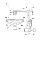
- the control unit 50 includes a CPU (Central Processing Unit) (not shown), a storage unit 51 such as a RAM (Random Access Memory) and a ROM (Read Only Memory), and various control data and operation buttons of the substrate processing apparatus 1. , And an input / output device and network equipment (not shown).
- the storage unit 51 stores a program for causing the substrate processing apparatus 1 to execute a predetermined operation, and can store various control data of the substrate processing apparatus 1 and the like.
- the CPU can sequentially execute the program while referring to the control data stored in the storage unit 51, thereby controlling the substrate processing apparatus 1 to execute a predetermined operation.
- control part 50 since the control part 50 also controls operation
- the control unit 50 of the present embodiment is a control panel provided on the opposite side of the load / unload unit 10 in the longitudinal direction of the housing 2.
- the control unit 50 is provided outside the housing 2, A personal computer having a display, a keyboard, or the like may be used.
- the storage unit 51 of the present embodiment is included in the control unit 50, but may be provided outside the control unit 50 or outside the substrate processing apparatus 1.
- the program of this embodiment is stored in the storage unit 51 such as a memory, but may be stored in another computer-readable storage medium (for example, an optical disk or a magnetic disk).
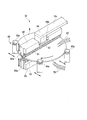
- the first cleaning device 31 is a device that first cleans the substrate W polished in the polishing unit 20. As shown in FIGS. 2 and 3, the first cleaning device 31 can scrub cleaning by contacting the first rotating mechanism 60 that holds and rotates the substrate W and one of the front and back surfaces of the substrate W.
- the central axis of the substrate W held by the first rotating mechanism 60 of this embodiment (a line passing through the center of the substrate W and perpendicular to the surface thereof) is parallel to the vertical direction, and the first roll along the central axis.
- the cleaning member 61 side is referred to as the upper side
- the second roll cleaning member 63 side is referred to as the lower side.
- the direction orthogonal to the vertical direction is called the horizontal direction.
- a direction orthogonal to the central axis line is referred to as a radial direction
- a direction around the central axis line is referred to as a circumferential direction.
- the first rotation mechanism 60 has a plurality of holding rollers 60a that hold the outer peripheral surface of the substrate W and rotate it around its central axis.
- the plurality of holding rollers 60a are each formed in a columnar shape extending in the vertical direction, and are disposed at intervals in the circumferential direction, and at least one of the plurality of holding rollers 60a is a drive unit such as a motor. It can be rotated around its central axis.
- the holding roller 60a that is not connected to the drive unit can freely rotate around its central axis. Further, the plurality of holding rollers 60a can be moved in the horizontal direction by a driving unit such as an air cylinder.
- the plurality of holding rollers 60a are moved radially outward from the state shown in FIG. evacuate.
- the plurality of holding rollers 60a are also applied when a downward load is applied from the first roll cleaning member 61 and an upward load is applied from the second roll cleaning member 63 to the substrate W held there.
- the substrate W can be held.
- the first roll cleaning member 61 is formed of a cylindrical PVA sponge or the like that can be elastically deformed and can pass through and retain a cleaning liquid (chemical liquid), pure water (DIW: De-Ionized Water), and the like around its central axis.
- the outer peripheral surface can contact the upper surface of the substrate W while rotating. That is, the central axis of the first roll cleaning member 61 extends in the horizontal direction.
- the total length of the first roll cleaning member 61 in the longitudinal direction is slightly larger than the diameter of the substrate W.
- An inner rinse supply unit (not shown) is provided inside the first roll cleaning member 61, and the cleaning liquid or the like supplied from the inner rinse supply unit into the first roll cleaning member 61 passes through the PVA sponge.
- the first roll cleaning member 61 is discharged outward from the outer peripheral surface.
- the first roll cleaning member 61 is supported by a first roll holder 65 so as to be rotatable around its central axis.
- the first roll holder 65 is formed in a prismatic shape extending in the horizontal direction, and brackets 65a projecting downward are provided at both ends in the longitudinal direction.
- a pair of brackets 65a rotatably supports both ends of the first roll cleaning member 61 in the longitudinal direction, and the first roll cleaning member 61 can be rotated by a driving unit such as a motor (not shown) for control.
- the unit 50 controls the drive unit.
- a concave portion 65b that is open upward is formed at the center of the first roll holder 65 in the longitudinal direction.
- a plate-like first load cell 62 is fixed to the bottom surface facing upward of the recess 65b.
- the upper surface of the first load cell 62 is connected to the distal end portion of the arm 71c in the first moving unit 71 described later via the first tilt mechanism 66. That is, the first roll cleaning member 61, the first roll holder 65, the first load cell 62, the first tilt mechanism 66, and the arm 71c are arranged in this order upward.
- the first load cell 62 is electrically connected to the control unit 50, and can output an electric signal indicating a tensile load or a compression load applied to the first load cell 62 to the control unit 50. Further, the center of the first load cell 62 is located on the central axis of the first roll cleaning member 61 in plan view.
- the first load cell 62 supports the first roll holder 65 and the first roll cleaning member 61 from above. Therefore, even when the first roll cleaning member 61 is not in contact with the substrate W, the weights of the first roll holder 65 and the first roll cleaning member 61 are applied to the first load cell 62 as tensile loads.
- the first load cell 62 can measure the load applied to the substrate W from the first roll cleaning member 61 and can output the measured value to the control unit 50. Further, the first load cell 62 of the present embodiment can measure a load (for example, N) applied to the substrate W to the second decimal place.
- the control unit 50 can control the first moving unit 71 based on the measurement value of the first load cell 62.
- the first tilt mechanism 66 extends in the horizontal direction and can swing the first roll holder 65 and the first roll cleaning member 61 about a rotation axis orthogonal to the longitudinal direction of the first roll cleaning member 61 in plan view. ing. For this reason, even if the substrate W held and rotated by the first rotation mechanism 60 is warped, tilted, or the like, for example, the first roll cleaning member 61 is moved to the upper surface of the substrate W by the first tilt mechanism 66. Can be swung along. Therefore, the first roll cleaning member 61 can uniformly apply a load to the substrate W, and can clean the upper surface of the substrate W uniformly.
- a plurality of first nozzles 67 capable of supplying a cleaning liquid, pure water, or the like to the upper surface of the substrate W are provided above the substrate W and at a position shifted from the first roll cleaning member 61 in plan view.
- the first moving unit 71 includes a motor 71a that is electrically connected to the control unit 50 and can be controlled by the control unit 50, a ball screw 71b coupled to the output shaft of the motor 71a, and an arm 71c that can be moved up and down by the ball screw 71b. It is equipped with.
- the motor 71a of this embodiment is a stepping motor, and the rotation angle and rotation speed of its output shaft are controlled by a pulse signal input from the control unit 50. Since the stepping motor operates in synchronization with the pulse signal, the current rotation angle of the output shaft of the motor 71a can be calculated by storing the number of pulses output by the control unit 50 to the motor 71a.
- the motor 71a is not limited to a stepping motor. For example, a servo motor having an encoder or the like may be used as the motor 71a.
- the ball screw 71b extends in the vertical direction and is integrally connected to the output shaft of the motor 71a, a nut member that is screwed into the screw member and moves up and down as the screw member rotates, and the nut member moves up and down. And a guide member for guiding. For this reason, when the output shaft of the motor 71a rotates, the nut member of the ball screw 71b can move in the vertical direction.
- the arm 71 c is a member that connects the ball screw 71 b and the first tilt mechanism 66.
- the arm 71c has a vertical portion that is integrally connected to the nut member of the ball screw 71b and extends in the vertical direction, and a horizontal portion that extends in the horizontal direction from the upper end of the vertical portion.
- a first tilt mechanism 66 is connected to the lower surface of the end portion on the opposite side of the ball screw 71b in the horizontal portion of the arm 71c.
- the said edge part in the horizontal part of the arm 71c is only called the front-end
- the nut member of the ball screw 71b is connected to the first roll cleaning member 61 via the arm 71c, the first tilt mechanism 66, the first load cell 62, and the first roll holder 65.
- the first roll cleaning member 61 can be moved up and down by moving the nut member of the ball screw 71 b up and down as the motor 71 a is driven, that is, it can be moved closer to and away from the substrate W.
- the control part 50 can calculate the present rotation angle of the output shaft in the motor 71a, it can calculate the present position of the up-down direction of the 1st roll cleaning member 61 based on a rotation angle.
- the second roll cleaning member 63 has the same configuration as that of the first roll cleaning member 61, and the outer peripheral surface thereof can contact the lower surface of the substrate W while rotating around its central axis.
- the second roll cleaning member 63 and the first roll cleaning member 61 are respectively provided on both sides in the vertical direction across the substrate W, and both the front and back surfaces of the substrate W can be scrubbed.
- the second roll cleaning member 63 is supported by a second roll holder 68 so as to be rotatable about its central axis.
- the second roll holder 68 is formed in a prismatic shape extending in the horizontal direction, and brackets 68a projecting upward are separately provided at both ends in the longitudinal direction.
- a pair of brackets 68a rotatably supports both ends of the second roll cleaning member 63 in the longitudinal direction, and the second roll cleaning member 63 can be rotated by a driving unit such as a motor (not shown) and controlled.
- the unit 50 controls the drive unit.
- a concave portion 68 b that opens downward is formed at the center of the second roll holder 68 in the longitudinal direction.
- the second roll holder 68 has a shape equivalent to that of the first roll cleaning member 61 and is disposed in a posture opposite to that of the first roll cleaning member 61 in the vertical direction.
- a plate-shaped second load cell 64 is fixed to the bottom surface of the recess 68b facing downward.
- the lower surface of the second load cell 64 is connected to an arm or the like (not shown) in the second moving unit 72 described later via a second tilt mechanism 69. That is, the second roll cleaning member 63, the second roll holder 68, the second load cell 64, and the second tilt mechanism 69 are arranged in this order downward.
- the second load cell 64 is electrically connected to the control unit 50, and can output an electrical signal indicating a tensile load or a compression load applied to the second load cell 64 to the control unit 50. Further, in the plan view, the center of the second load cell 64 is located on the central axis of the second roll cleaning member 63. The second load cell 64 supports the second roll holder 68 and the second roll cleaning member 63 from below. For this reason, even when the second roll cleaning member 63 is not in contact with the substrate W, the weight of the second roll holder 68 and the second roll cleaning member 63 is applied to the second load cell 64 as a compressive load.
- the second load cell 64 can measure the load applied to the substrate W from the second roll cleaning member 63 and can output the measurement value to the control unit 50. Further, the second load cell 64 of the present embodiment can measure the load (for example, N) applied to the substrate W to the second decimal place.
- the control unit 50 can control the second moving unit 72 based on the measurement value of the second load cell 64.
- the second tilt mechanism 69 can swing the second roll holder 68 and the second roll cleaning member 63 around a rotation axis that extends in the horizontal direction and is orthogonal to the longitudinal direction of the second roll cleaning member 63 in plan view. ing. Therefore, even when the substrate W held and rotated by the first rotation mechanism 60 is warped, tilted, or the like, for example, the second roll cleaning member 63 is moved to the lower surface of the substrate W by the second tilt mechanism 69. Can be swung along. Therefore, the second roll cleaning member 63 can uniformly apply a load to the substrate W, and can uniformly clean the lower surface of the substrate W.
- a plurality of second nozzles 70 capable of supplying a cleaning liquid, pure water, and the like to the lower surface of the substrate W are provided below the substrate W and at positions shifted from the second roll cleaning member 63 in plan view.
- the second moving unit 72 includes a motor 72a that is electrically connected to the control unit 50 and can be controlled by the control unit 50, a ball screw 72b coupled to the output shaft of the motor 72a, and an arm (not shown) that can be moved up and down by the ball screw 72b. Etc.
- the motor 72a of this embodiment is a stepping motor like the motor 71a, and the controller 50 calculates the current rotation angle of the output shaft of the motor 72a by storing the number of pulses output to the motor 72a. it can.
- the motor 72a is not limited to a stepping motor.
- a servo motor having an encoder or the like may be used as the motor 72a.
- the ball screw 72b extends in the vertical direction and is integrally connected to the output shaft of the motor 72a, a nut member that is screwed into the screw member and moves up and down as the screw member rotates, and the nut member moves up and down. And a guide member for guiding. For this reason, when the output shaft of the motor 72a rotates, the nut member of the ball screw 72b can move in the vertical direction.
- the arm of the second moving part 72 is a member that connects the nut member of the ball screw 72b and the second tilt mechanism 69.
- a bracket or the like may be used.
- the nut member of the ball screw 72b is connected to the second roll cleaning member 63 through the arm, the second tilt mechanism 69, the second load cell 64, and the second roll holder 68. For this reason, the second roll cleaning member 63 can be moved up and down by moving the nut member of the ball screw 72 b up and down as the motor 72 a is driven.
- the control part 50 can calculate the present rotation angle of the output shaft in the motor 72a, it can calculate the present position of the 2nd roll cleaning member 63 in the up-down direction based on the rotation angle.
- the second cleaning device 32 is a device for further cleaning the substrate W cleaned by the first cleaning device 31.
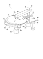
- the second cleaning device 32 includes a second rotating mechanism 80 that holds and rotates the substrate W, and a cylindrical pencil cleaning member that can contact the upper surface of the substrate W and perform scrub cleaning. (Cleaning member) 81, a third load cell (measuring unit) 82 for measuring the load of the pencil cleaning member 81 on the substrate W, and a third moving unit (moving unit) capable of pressing the pencil cleaning member 81 against the upper surface of the substrate W 83.
- the central axis of the substrate W held by the second rotation mechanism 80 of this embodiment is parallel to the vertical direction.
- the second rotation mechanism 80 includes a motor 80b as a drive unit, and a plurality of (four in this embodiment) arms 80c that are connected to the output shaft of the motor 80b and extend upward and radially outward.
- the holding portions 80a capable of holding the outer peripheral surface of the substrate W are disposed at the radially outer ends of the arms 80c.
- the plurality of holding portions 80a are arranged at intervals in the circumferential direction.
- the second rotating mechanism 80 can rotate the substrate W around its central axis by driving the motor 80b in a state where the substrate W is held by the plurality of holding portions 80a.
- the plurality of holding portions 80a can hold the substrate W even when a downward load is applied from the pencil cleaning member 81 to the substrate W held there.
- the pencil cleaning member 81 is formed of a cylindrical PVA sponge or the like that can be elastically deformed and can pass and retain cleaning liquid (chemical liquid), pure water, etc., and its central axis is parallel to the vertical direction.
- the lower end surface can come into contact with the upper surface of the substrate W while rotating around.
- the lower end surface of the pencil cleaning member 81 is parallel to the upper surface of the substrate W held by the second rotation mechanism 80.
- the pencil cleaning member 81 is supported by, for example, a third roll holder 81a formed in a cylindrical shape with a top, and is provided so as to protrude downward from the third roll holder 81a.
- the pencil cleaning member 81 can be rotated around its central axis by a driving unit such as a motor (not shown), and the control unit 50 controls the driving unit.
- An upper end portion of the third roll holder 81a is connected to a tip end portion of an arm 83c in a third moving portion 83 to be described later via a plate-like third load cell 82. That is, the pencil cleaning member 81, the third roll holder 81a, the third load cell 82, and the arm 83c are arranged in this order upward.
- the third load cell 82 is electrically connected to the control unit 50, and can output an electric signal indicating a tensile load or a compression load applied to the third load cell 82 to the control unit 50. Further, in the plan view, the center of the third load cell 82 is disposed at the same position as the central axis of the pencil cleaning member 81.
- the third load cell 82 supports the third roll holder 81a and the pencil cleaning member 81 from above. For this reason, even when the pencil cleaning member 81 is not in contact with the substrate W, the weight of the third roll holder 81a and the pencil cleaning member 81 is applied to the third load cell 82 as a tensile load.
- the pencil cleaning member 81 presses the upper surface of the substrate W
- the pencil cleaning member 81 receives an upward reaction force from the substrate W, so that the tensile load applied to the third load cell 82 is reduced, and this reduction amount is reduced.
- the third load cell 82 can measure the load applied to the substrate W from the pencil cleaning member 81 and can output the measured value to the control unit 50.
- the third load cell 82 of the present embodiment can measure the load (for example, N) applied to the substrate W to the second decimal place.
- the control unit 50 can control the third moving unit 83 based on the measurement value of the third load cell 82.
- a plurality of second liquids that can supply cleaning liquid, pure water, or the like to the upper surface of the substrate W at a position that does not interfere with the arm 83c and the pencil cleaning member 81 when the arm 83c of the third moving unit 83 swings above the substrate W.
- Three nozzles 84 are provided.
- the third moving unit 83 is electrically connected to the control unit 50 and can be controlled by the control unit 50, a vertical movement motor 83a, a ball screw 83b connected to the output shaft of the vertical movement motor 83a, and a vertical movement by the ball screw 83b. And a swing motor 83d that is electrically connected to the control unit 50 and can be controlled by the control unit 50.
- the vertical movement motor 83a of the present embodiment is a stepping motor like the motor 71a of the first cleaning device 31, and the control unit 50 stores the number of pulses output to the vertical movement motor 83a and the like to move up and down.
- the current rotation angle of the output shaft in the motor 83a can be calculated.
- the vertical movement motor 83a is not limited to a stepping motor, and for example, a servo motor having an encoder or the like may be used as the vertical movement motor 83a.
- the ball screw 83b includes a screw member that extends in the vertical direction and is integrally connected to the output shaft of the vertical movement motor 83a, a nut member that is screwed into the screw member and moves up and down as the screw member rotates, and a vertical movement of the nut member And a guide member for guiding the movement. For this reason, the nut member of the ball screw 83b can move in the vertical direction by rotating the output shaft of the vertical movement motor 83a.
- the arm 83 c is a member that connects the ball screw 83 b and the third load cell 82.
- the arm 83c has a vertical portion that is connected to the nut member of the ball screw 83b and extends in the vertical direction, and a horizontal portion that extends in the horizontal direction from the upper end of the vertical portion.
- the third load cell 82 is connected to the lower surface of the end portion opposite to the ball screw 83b in the horizontal portion of the arm 83c. Note that the end portion of the arm 83c in the horizontal portion is simply referred to as the tip portion of the arm 83c.
- the nut member of the ball screw 83b is connected to the pencil cleaning member 81 via the arm 83c, the third load cell 82, and the third roll holder 81a.
- the pencil cleaning member 81 can be moved up and down by moving the nut member of the ball screw 83 b up and down as the vertical movement motor 83 a is driven.
- the control unit 50 can calculate the current rotation angle of the output shaft of the vertical movement motor 83a, and therefore can calculate the current vertical position of the pencil cleaning member 81 based on the rotation angle.
- the output shaft of the swing motor 83d is connected to a connecting member or the like (not shown), and a case of the vertical movement motor 83a and a guide member of the ball screw 83b are integrally connected to the connecting member. For this reason, by the operation of the swing motor 83d, the vertical movement motor 83a and the ball screw 83b rotate around the central axis R of the output shaft of the swing motor 83d, and thus the arm 83c swings around the central axis R. Therefore, the pencil cleaning member 81 can swing around the central axis R.
- the swing motor 83d of this embodiment is a stepping motor like the vertical movement motor 83a, and the control unit 50 stores the number of pulses output to the swing motor 83d and the like so that the output from the swing motor 83d is stored.
- the current rotation angle of the axis can be calculated. Therefore, the control unit 50 can calculate the current position around the central axis R of the pencil cleaning member 81 based on the current rotation angle of the swing motor 83d.
- the swing motor 83d is not limited to a stepping motor, and for example, a servo motor having an encoder or the like may be used as the swing motor 83d.
- the pencil cleaning member 81 comes close to the substrate W and contacts the center O on the upper surface of the substrate W by the operation of the third moving unit 83 controlled by the control unit 50 and rotates.
- the third moving unit 83 controlled by the control unit 50 and rotates.
- a pedestal portion 85 extending in the vertical direction is provided at a position different from the substrate W held by the second rotation mechanism 80 in plan view.
- the upper end portion of the pedestal portion 85 is disposed on the swing path of the pencil cleaning member 81 in a plan view, and the swinging pencil cleaning member 81 can come into contact with the upper end surface of the pedestal portion 85.
- the upper end portion of the pedestal portion 85 is constituted by a quartz plate whose upper end surface is perpendicular to the vertical direction, and the quartz plate is disposed at the same position in the vertical direction as the upper surface of the substrate W held by the second rotation mechanism 80. Having an upper end surface.
- the quartz plate of the pedestal portion 85 is formed in a circular shape, and the outer diameter thereof is larger than the outer diameter of the pencil cleaning member 81.
- the quartz plate of the pedestal portion 85 comes into contact with the pencil cleaning member 81 so that the particles on the substrate W attached to the pencil cleaning member 81 can be removed from the pencil cleaning member 81.
- a fourth nozzle 86 capable of supplying pure water or the like to the upper end surface of the pedestal portion 85 is provided above the pedestal portion 85. By supplying pure water or the like from the fourth nozzle 86 to the upper end surface of the pedestal portion 85, particles adhering to the quartz plate can be washed away.
- the operation of the substrate processing apparatus 1 of this embodiment will be described.
- the operations of the loading / unloading unit 10, the polishing unit 20, the drying device 33 in the cleaning unit 30, and the substrate transport unit 40 are the same as those in the prior art, and thus description thereof is omitted.
- the reference positions of the roll cleaning members 61 and 63 that are close to the substrate W and are in a non-contact position are set, and the roll cleaning members 61 and 63 are the substrates.
- a reset operation for setting the measured values of the load cells 62 and 64 in a state in which the load cells 62 and 64 are not in contact with W to zero and a pressing operation for verifying whether the maintenance has been properly performed will be described.
- the reset operation and the pressing operation of the first cleaning device 31 are performed by the control unit 50 controlling the first cleaning device 31.
- the vertical movement of the roll cleaning members 61 and 63 is performed by the control unit 50. This is performed by controlled moving units 71 and 72, respectively.
- cleaning apparatus 31 is performed because the control part 50 performs the program memorize
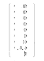
- FIGS. 6A to 6H show that the reset operation proceeds in this order.
- a reset load for example, 1.1 N
- the first cleaning device 31 is set in advance by input via the display unit 52 or the like.
- the control unit 50 After the replacement of the parts (for example, the first roll cleaning member 61 and the first load cell 62) and the adjustment are performed by the maintenance of the first cleaning device 31, and before the cleaning operation for the substrate W, the control unit 50 The operator operates the “first cleaning device: reset operation start button” displayed on the display unit 52. This operation may be performed when the first roll cleaning member 61 is already at the origin position. By performing the operation, the controller 50 first moves the first roll cleaning member 61 to the origin position. Also good. In the present description, the first load cell 62 is replaced even when the first roll cleaning member 61 is not in contact with the substrate W by replacing the first roll cleaning member 61 and the like by maintenance of the first cleaning device 31. The measured value is 0.3 N (see FIGS.
- the first load cell 62 shows a load different from the actual load on the substrate W of the first roll cleaning member 61.
- the substrate W polished by the polishing unit 20 is transferred from the substrate transport unit 40 to the first cleaning device 31 and held by the first rotation mechanism 60.
- the unpolished substrate W may be transferred from the substrate transport unit 40 to the first cleaning device 31.
- the reference member of this embodiment is formed of the substrate W.
- the first rotation mechanism 60 rotates the substrate W, and pure water or the like is supplied from the inner rinse supply unit to the inside of the first roll cleaning member 61. Is rotated about its central axis.
- the rotation speed of the first roll cleaning member 61 is, for example, 200 min-1.
- pure water or the like is not supplied from the first nozzle 67 during the reset operation, but pure water or the like may be supplied from the first nozzle 67 to the upper surface of the substrate W during the reset operation.
- the rotation speed of the substrate W, the presence / absence of the inner rinse, the supply amount thereof, and the rotation speed of the first roll cleaning member 61 may be adjusted as appropriate.
- the control unit 50 directs the first roll cleaning member 61 toward the upper surface of the substrate W, From the origin position, it is moved at a high speed to the reference position currently stored in the storage unit 51 (reference position used before maintenance, hereinafter referred to as the previous reference position) (FIG. 6A).
- the first roll cleaning member 61 may start moving toward the substrate W simultaneously with the start of the rotation.
- the control unit 50 moves the first roll cleaning member 61 toward the substrate W at a low speed (FIG. 6B).
- the speed ratio of the low speed movement to the high speed movement of the first roll cleaning member 61 is, for example, 100/5.
- the control unit 50 presses the first roll cleaning member 61 in contact with the upper surface of the substrate W.
- the control unit 50 further moves the first roll cleaning member 61 to the substrate W side at a low speed, and acquires and refers to the measurement value of the first load cell 62.
- the reaction force that the first roll cleaning member 61 receives from the substrate W increases with the movement of the first roll cleaning member 61, and thus the measured value of the first load cell 62 is measured. Gradually increases.
- the controller 50 stops the movement of the first roll cleaning member 61 (FIG. 6C).
- the first roll cleaning member 61 is moved by a unit movement amount (for example, 0.1 mm) and stopped to determine whether the measured value of the first load cell 62 has reached the reset load.
- the control unit 50 may confirm during the stop, and the movement and confirmation may be repeated.
- the controller 50 moves the first roll cleaning member 61 at a low speed in a direction away from the substrate W while referring to the measurement value of the first load cell 62.
- the reaction force that the first roll cleaning member 61 receives from the substrate W decreases, so the measured value of the first load cell 62 gradually decreases (FIG. 6D).
- the control unit 50 stores the measurement value of the first load cell 62 for each unit movement amount (for example, 0.1 mm) of the first roll cleaning member 61 in the storage unit 51, and the measurement value continues at least twice. When the positions become equal to each other (FIGS.
- the position of the first roll cleaning member 61 at that time is set as a new reference position of the first roll cleaning member 61 at the time of cleaning.
- a reset operation is performed in which the measured value of the first load cell 62 at the time point is set as the pressing reference value at the time of cleaning.
- the control unit 50 assumes that the load on the substrate W is zero, and the display unit 52 The closed loop control of the load with respect to the substrate W at the time of the display of the load and the later-described cleaning is performed.
- the first roll cleaning member 61 is stopped by moving the first roll cleaning member 61 in a direction away from the substrate W by a unit movement amount (for example, 0.1 mm). While the movement of the roll cleaning member 61 is stopped, the measurement value of the first load cell 62 may be stored in the storage unit 51 and compared with the previous measurement value, and these movements and comparisons may be repeated. On the other hand, the storage unit 51 stores the measurement value of the first load cell 62 every time the first roll cleaning member 61 moves the unit movement amount while continuously moving the first roll cleaning member 61 at a low speed. And the comparison with the previous measurement value may be sequentially performed.
- a unit movement amount for example, 0.1 mm
- the determination as to whether or not the measurement values of the first load cell 62 are equal to each other at least twice in succession is, for example, based on whether or not the values of the first load cell 62 are the same as the first decimal place. It may be determined, or may be determined based on whether or not the value obtained by rounding off the value of the second decimal place of the measurement value of the first load cell 62 is the same.
- a predetermined threshold value for example, 0.1 N
- the first threshold value is set. It may be determined that the measured value of the load cell 62 is equivalent at least twice continuously.
- the reset operation is performed when the measurement values of the first load cell 62 are equal to each other twice in succession. However, the measurement value of the first load cell 62 is equal to three times or more in succession. The reset operation may be performed when
- control unit 50 moves the first roll cleaning member 61 from the origin position to the previous reference position at a high speed, but the high speed movement is not an essential requirement for the maintenance method of the present embodiment.
- a method may be used in which the reset operation is performed without moving the first roll cleaning member 61 at a high speed. For example, a method of performing the reset operation without moving the first roll cleaning member 61 at high speed will be described with reference to FIG.
- the control unit 50 presses the first roll cleaning member 61 against the upper surface of the substrate W, and moves it from the state toward the substrate W (step S1 in FIG. 7). Subsequently, the control unit 50 acquires the measurement value of the first load cell 62 (step S2 in FIG. 7). The measurement value may be acquired for each unit movement amount of the first roll cleaning member 61. Subsequently, the control unit 50 determines whether or not the measurement value acquired in step S2 has reached a reset load (for example, 1.1 N) (step S3 in FIG. 7). If the measured value acquired in step S2 has not reached the reset load, step S1 is performed again.
- a reset load for example, 1.1 N
- step S4 the control unit 50 acquires the measurement value of the first load cell 62 for each unit movement amount of the first roll cleaning member 61 (step S5 in FIG. 7).
- step S6 the control unit 50 determines whether or not the measurement values acquired in step S5 are equal to each other at least twice consecutively (step S6 in FIG. 7).
- step S8 in FIG. 7 when the measured values acquired in step S5 are equal to each other at least twice in succession, a reset operation is performed (step S8 in FIG. 7). From the above, the reset operation related to the first roll cleaning member 61 of the first cleaning device 31 is completed.
- the first roll cleaning member 61 By performing such a reset operation, even if the previous reference position of the first roll cleaning member 61 is improperly spaced from the upper surface of the substrate W after maintenance, the first roll cleaning member 61 The reference position can be set appropriately. Further, by performing the above reset operation, even if the measured value of the first load cell 62 is different before and after the maintenance, by setting the pressing reference value, the display in the state shown in FIG. The load on the substrate W of the first roll cleaning member 61 displayed on the part 52 can be displayed as zero. Therefore, an accurate load applied to the substrate W can be shown to the operator through the display unit 52 and the like.
- a pressing operation for verifying whether the maintenance related to the first roll cleaning member 61 of the first cleaning device 31 has been appropriately performed will be described.
- a plurality of test loads for example, 0.8N, 1.2N, and 1.6N
- the number of test loads is not limited to three, but may be one or two, or four or more.
- This operation may be performed when the first roll cleaning member 61 is already at the origin position, or by performing the operation, the controller 50 first moves the first roll cleaning member 61 to the origin position. Also good.
- the first rotating mechanism 60 is in a state where the substrate W used in the reset operation is held.
- the rotational speed of the substrate W under the control of the control unit 50, the rotational speed of the substrate W, the presence / absence of the inner rinse to the first roll cleaning member 61, the rotational speed of the first roll cleaning member 61, and pure water from the first nozzle 67, etc.
- the presence or absence of supply, etc. is adjusted as appropriate. These conditions may be the same as or different from those at the time of cleaning the substrate W.
- control unit 50 moves the first roll cleaning member 61 toward the upper surface of the substrate W from the origin position to the reference position after the reset operation currently stored in the storage unit 51 at a high speed.
- the controller 50 determines that the load on the substrate W of the first roll cleaning member 61, that is, the measured value of the first load cell 62 is the first test load (0 .8N) until closed loop control is performed.
- the control unit 50 controls the first moving unit 71 based on the difference between the measured value of the first load cell 62 and the first test load when the pressing reference value set in the reset operation is zero. Then, the measured value of the first load cell 62 is matched with the first test load.
- the pressing operation for the first test load is completed.
- the measured value of the first load cell 62 when the pressing operation is completed, the amount of movement of the first roll cleaning member 61 from the start to the completion of the pressing operation (specifically, the amount of movement from the origin position to the reference position, and the reference
- the elapsed time from the start to the end of the pressing operation (specifically, the elapsed time from the origin position to the reference position, and the pressing operation completed from the reference position)
- At least one of the measured time of the first load cell 62 from the start to the completion of the pressing operation is stored in the storage unit 51.
- control unit 50 similarly performs the pressing operation on the second test load (1.2N) and the third test load (1.6N).
- the results are stored in the storage unit 51, and the operator can check these results through the display unit 52 and the like. Thereby, it can be confirmed whether the maintenance regarding the 1st roll cleaning member 61 of the 1st cleaning apparatus 31 is completed appropriately. Moreover, when the said result differs from the expected result, it can also be estimated which part of the 1st washing
- the measured value of the first load cell 62 when the pressing operation is completed is different from the test load, for example, the first load cell 62, the first moving unit 71, or the control unit 50 may be readjusted. .
- the reference position of the first roll cleaning member 61 Is not set appropriately, that is, the reference position is set at a position away from the substrate, or the first moving unit 71 or the control unit 50 or the like needs to be readjusted.
- the maximum value among the measured values of the first load cell 62 from the start to the completion of the pressing operation is larger than the expected value, for example, the moving speed of the first roll cleaning member 61 by the first moving unit 71 is used.
- the reset operation and the pressing operation related to the second roll cleaning member 63 of the first cleaning device 31 are the same as those of the first cleaning device 31 except that the relationship with the substrate W is opposite to that of the first roll cleaning member 61 in the vertical direction. Since it is the same as the reset operation and the pressing operation related to the first roll cleaning member 61, the description thereof is omitted.
- the reset operation regarding the roll cleaning members 61 and 63 of the first cleaning device 31 is performed at different times. Further, in the pressing operation of the roll cleaning members 61 and 63 of the first cleaning device 31, when two or more test loads are set, respectively, one pressing operation of the roll cleaning members 61 and 63 is first performed. Alternatively, the pressing operation of the roll cleaning members 61 and 63 may be performed alternately.
- the cleaning operation for the substrate W using the roll cleaning members 61 and 63 of the first cleaning device 31 will be described.
- the cleaning operation for the substrate W by the first cleaning device 31 is performed by the control unit 50 controlling the first cleaning device 31.
- the cleaning operation of the first cleaning device 31 is performed by the control unit 50 sequentially executing the program stored in the storage unit 51.
- the substrate W polished by the polishing unit 20 is transferred to the first cleaning device 31 via the substrate transport unit 40 and held by the first rotation mechanism 60.
- the roll cleaning members 61 and 63 are at the respective origin positions.
- the inner rinse is supplied to the inside of each of the roll cleaning members 61 and 63, and pure water or the like is supplied from the nozzles 67 and 70 to the upper and lower surfaces of the substrate W, respectively.
- the rotation speed of the substrate W by driving the mechanism 60 is adjusted to a predetermined value, and the rotation speeds of the roll cleaning members 61 and 63 are adjusted to a predetermined value.
- the roll cleaning members 61 and 63 rotate in opposite directions. Further, the control unit 50 moves the roll cleaning members 61 and 63 from each origin position to each reference position at high speed.
- the control unit 50 determines that the load on the substrate W of the first roll cleaning member 61, that is, the measured value of the first load cell 62 is the first target load (target (Closed loop control) until the load on the substrate W of the second roll cleaning member 63, that is, the measured value of the second load cell 64 matches the second target load (target load). I do. In these closed loop controls, the control unit 50 determines the difference between the measured value of the first load cell 62 and the first target load when the pressing reference value set in the reset operation for the first roll cleaning member 61 is zero.
- the second moving unit 72 Based on the first moving unit 71, the measured value of the second load cell 64 when the pressing reference value set in the reset operation for the second roll cleaning member 63 is zero, the second target load, Based on the difference, the second moving unit 72 is controlled. Since the measured values of the load cells 62 and 64 when the pressing reference value set in the reset operation is set to zero are used in the closed loop control, the load applied to the substrate W can be appropriately matched with the target load. It is also possible to set different values for the first and second target loads.
- the control unit 50 moves the roll cleaning members 61 and 63 at a low speed.
- the speed ratio of the low speed movement to the high speed movement of the roll cleaning members 61 and 63 is, for example, 100/5.
- the reference positions of the roll cleaning members 61 and 63 are appropriately set to positions that are close to the substrate W and are not in contact with each other. Therefore, the distance that the roll cleaning members 61 and 63 move at high speed. And the distance traveled at a low speed can be shortened, so that the time required for the cleaning process by the first cleaning device 31 can be shortened.
- each reference position of the roll cleaning members 61 and 63 is set to a position not in contact with the substrate W, the roll cleaning members 61 and 63 when contacting the substrate W are moving at a low speed. The impact when the roll cleaning members 61 and 63 come into contact with the substrate W can be kept low.
- the roll cleaning members 61 and 63 are pressed against the upper and lower surfaces of the substrate W by the first and second target loads, respectively. In this state, scrub cleaning for the substrate W is performed for a predetermined time.
- the roll cleaning members 61 and 63 are separated from the substrate W, and the substrate W is taken out from the first rotation mechanism 60 and transferred to the second cleaning device 32 by the second transport robot 34. Thereby, the cleaning process for the substrate W in the first cleaning apparatus 31 is completed.
- the reference position of the pencil cleaning member 81 that is close to and non-contact with the substrate W is set, and the pencil cleaning member 81 is attached to the substrate W.
- a reset operation for setting the measured value of the third load cell 82 to zero in a non-contact state and a pressing operation for verifying whether maintenance has been properly performed will be described.
- the reset operation and the pressing operation of the second cleaning device 32 are performed by the control unit 50 controlling the second cleaning device 32.
- the vertical movement of the pencil cleaning member 81 is controlled by the control unit 50. This is performed by the third moving unit 83.
- cleaning apparatus 32 is performed because the control part 50 performs the program memorize
- a reset operation related to the second cleaning device 32 will be described with reference to FIG. 8A to 8H show that the reset operation proceeds in this order.
- a reset load for example, 2.0 N
- the second cleaning device 32 is set in advance by input via the display unit 52 or the like.
- the display unit of the control unit 50 after the replacement or adjustment of parts is performed by the maintenance of the second cleaning device 32 and before the cleaning operation for the substrate W.
- the operator operates the “second cleaning device: reset operation start button” displayed at 52. This operation may be performed when the pencil cleaning member 81 is already at the origin position, or the controller 50 may first move the pencil cleaning member 81 to the origin position by performing the operation.
- the measured value of the third load cell 82 is obtained even when the pencil cleaning member 81 is not in contact with the substrate W. 0.3N (see FIGS.
- the third load cell 82 shows a load different from the actual load of the pencil cleaning member 81 on the substrate W.
- the substrate W cleaned by the first cleaning device 31 is transferred to the second cleaning device 32 via the second transport robot 34 and held by the second rotating mechanism 80.
- the unpolished substrate W may be transferred from the second transfer robot 34 or the like to the second cleaning device 32.
- the second rotating mechanism 80 rotates the substrate W, the pencil cleaning member 81 is rotated around its central axis, and pure water or the like is supplied from the third nozzle 84 to the upper surface of the substrate W.
- the rotation speed of the substrate W is, for example, 500 mim-1
- the rotation speed of the pencil cleaning member 81 is, for example, 50 min-1
- the supply amount of pure water or the like from the third nozzle 84 to the substrate W is, for example, 1000 L / min.
- the rotation speed of the substrate W, the rotation speed of the pencil cleaning member 81, and the supply amount of pure water or the like from the third nozzle 84 may be adjusted as appropriate.
- the control unit 50 directs the pencil cleaning member 81 toward the upper surface of the substrate W from the origin position. Then, it is moved at a high speed to a reference position currently stored in the storage unit 51 (reference position used before maintenance, hereinafter referred to as the previous reference position) (FIG. 8A).
- the pencil cleaning member 81 may start moving toward the substrate W simultaneously with the start of the rotation.
- the control unit 50 moves the pencil cleaning member 81 toward the substrate W at a low speed (FIG. 8B).
- the speed ratio of the low speed movement to the high speed movement of the pencil cleaning member 81 is, for example, 100/5.
- the control unit 50 makes the pencil cleaning member 81 come into contact with the upper surface of the substrate W and presses it.
- the control unit 50 further moves the pencil cleaning member 81 toward the substrate W at a low speed, and acquires and refers to the measurement value of the third load cell 82.
- the control unit 50 stops the movement of the pencil cleaning member 81 (FIG. 8C).
- the pencil cleaning member 81 is moved and stopped by a unit movement amount (for example, 0.1 mm), and whether the measured value of the third load cell 82 has reached the reset load is controlled while the movement of the pencil cleaning member 81 is stopped.
- the unit 50 may confirm and repeat the movement and confirmation.
- the controller 50 determines whether the measured value of the third load cell 82 has reached the reset load every time the pencil cleaning member 81 moves the unit movement amount while continuously moving the pencil cleaning member 81 at a low speed. The movement of the pencil cleaning member 81 may be stopped when it is confirmed and reached.
- the control unit 50 moves the pencil cleaning member 81 at a low speed in a direction away from the substrate W while referring to the measurement value of the third load cell 82.
- the reaction force received by the pencil cleaning member 81 from the substrate W decreases, so that the measured value of the third load cell 82 gradually decreases (FIG. 8 (d) to FIG. 8 ( g)).
- the control unit 50 stores the measurement value of the third load cell 82 for each unit movement amount (for example, 0.1 mm) of the pencil cleaning member 81 in the storage unit 51, and the measurement value is continuously at least twice. At the same time (FIGS.
- the position of the pencil cleaning member 81 at that time is set as a new reference position of the pencil cleaning member 81 at the time of cleaning, and the storage unit 51 And the reset operation for setting the measured value of the third load cell 82 at the time point as the pressing reference value at the time of cleaning is performed.
- the control unit 50 assumes that the load on the substrate W is zero, and the display unit 52 The closed loop control of the load with respect to the substrate W at the time of the display of the load and the later-described cleaning is performed.
- the measurement value of the third load cell 82 is stored in the storage unit 51 by moving the pencil cleaning member 81 in a direction away from the substrate W by a unit movement amount (for example, 0.1 mm) and stopping the pencil cleaning member 81. While the movement is stopped, the measurement value of the third load cell 82 may be stored in the storage unit 51 and compared with the previous measurement value, and these movements and comparisons may be repeated. On the other hand, the measurement value of the third load cell 82 is stored in the storage unit 51 each time the pencil cleaning member 81 moves a unit movement amount while continuously moving the pencil cleaning member 81 in the direction of separation, and the previous time. Comparison with the measured values may be performed sequentially.
- a unit movement amount for example, 0.1 mm
- the determination as to whether or not the measured values of the third load cell 82 are equal to each other at least twice in succession is, for example, based on whether or not the measured values of the third load cell 82 are the same as the first decimal place. It may be determined, or may be determined based on whether or not the value obtained by rounding off the value of the second decimal place of the measurement value of the third load cell 82 is the same. Further, when a predetermined threshold value (for example, 0.1 N) is stored in the storage unit 51 and the difference between the measurement values of the third load cell 82 measured continuously at least twice is smaller than the threshold value, the third threshold value is set. It may be determined that the measured value of the load cell 82 is equivalent at least twice continuously. In this example, the reset operation is performed when the measurement values of the third load cell 82 are equal to each other twice in succession, but the measurement value of the third load cell 82 is equal to three times or more in succession. The reset operation may be performed when
- the control unit 50 moves the pencil cleaning member 81 from the origin position to the previous reference position at a high speed.
- the high speed movement is not an essential requirement for the maintenance method of the present embodiment.
- a method may be used in which the reset operation is performed without moving the member 81 at a high speed. Note that a method of performing the reset operation without moving the pencil cleaning member 81 at high speed is shown in the flowchart shown in FIG. 7 used in the description of the first cleaning device 31, and therefore the description thereof is omitted.
- the reset load for the pencil cleaning member 81 may be changed as appropriate.
- the reset operation is performed by pressing the pencil cleaning member 81 against the upper surface of the substrate W.
- the second cleaning device is pressed by pressing the pencil cleaning member 81 against the upper end surface of the pedestal portion 85.
- 32 reset operations may be performed.
- the upper end portion (quartz plate) of the pedestal portion 85 has an upper end surface disposed at the same position in the vertical direction as the upper surface of the substrate W held by the second rotation mechanism 80. It is also possible to perform a reset operation of the second cleaning device 32 using the upper end surface.
- the reference member of the present embodiment is formed by the substrate W or the pedestal portion 85. In the reset operation when the pedestal portion 85 is used, the rotational speed of the pencil cleaning member 81 and the supply amount of pure water or the like from the fourth nozzle 86 may be adjusted as appropriate. As described above, the reset operation related to the second cleaning device 32 is completed.
- the reference position of the pencil cleaning member 81 is appropriately set. Can be set to Further, by performing the reset operation, even if the measured value of the third load cell 82 is different before and after the maintenance, by setting the pressing reference value, the display in the state shown in FIG. The load on the substrate W of the pencil cleaning member 81 displayed on the part 52 can be displayed as zero. Therefore, an accurate load applied to the substrate W can be shown to the operator through the display unit 52 and the like.
- a pressing operation for verifying whether the second cleaning device 32 has been properly maintained will be described.
- the description is abbreviate
- a plurality of test loads (for example, 0.8 N, 1.4 N, and 2.0 N) for the second cleaning device 32 are preset in the storage unit 51 by input via the display unit 52 or the like.
- the number of test loads is not limited to three, but may be one or two, or four or more.
- the rotation speed of the substrate W, the rotation speed of the pencil cleaning member 81, the presence / absence of supply of pure water or the like from the third nozzle 84, and the like are appropriately adjusted. These conditions may be the same as or different from those at the time of cleaning the substrate W.
- control unit 50 moves the pencil cleaning member 81 toward the upper surface of the substrate W, and moves the pencil cleaning member 81 from the origin position to the reference position after the reset operation currently stored in the storage unit 51 at high speed.
- the control unit 50 determines that the load of the pencil cleaning member 81 on the substrate W, that is, the measured value of the third load cell 82 becomes the first test load (0.8 N). Closed loop control is performed until they match. In the closed loop control, the control unit 50 controls the first moving unit 71 based on the difference between the measured value of the third load cell 82 and the first test load when the pressing reference value set in the reset operation is zero. Then, the measured value of the third load cell 82 is matched with the first test load.
- the pressing operation for the first test load is completed.
- control unit 50 similarly performs the pressing operation on the second test load (1.4N) and the third test load (2.0N).
- the results are stored in the storage unit 51, and the operator can check these results through the display unit 52 and the like. Thereby, it can be confirmed whether the maintenance regarding the pencil cleaning member 81 of the second cleaning device 32 is properly completed. Thus, the pressing operation of the pencil cleaning member 81 in the second cleaning device 32 is completed.
- the substrate W cleaned by the first cleaning device 31 is transferred to the second cleaning device 32 via the second transport robot 34 and is held by the second rotation mechanism 80. At this time, the pencil cleaning member 81 is at the origin position.
- the control unit 50 controls pure water or the like from the third nozzle 84 to the upper surface of the substrate W, the rotation speed of the substrate W is adjusted by driving the second rotation mechanism 80, and the pencil cleaning member 81. Is adjusted to a predetermined value. Further, the control unit 50 moves the pencil cleaning member 81 from the origin position to the reference position at high speed.
- the control unit 50 performs closed loop control until the load of the pencil cleaning member 81 on the substrate W, that is, the measured value of the third load cell 82 matches the target load. .
- the control unit 50 is based on the difference between the measured value of the third load cell 82 when the pressing reference value set in the reset operation related to the pencil cleaning member 81 is zero and the target load.
- the third moving unit 83 is controlled. Since the measured value of the third load cell 82 when the pressing reference value set in the reset operation is zero is used in the closed loop control, the load applied to the substrate W can be appropriately matched with the target load.
- the control unit 50 moves the pencil cleaning member 81 at a low speed.
- the speed ratio of the low speed movement to the high speed movement of the pencil cleaning member 81 is, for example, 100/5.
- the reference position of the pencil cleaning member 81 is appropriately set close to the substrate W and in a non-contact position, so that the distance that the pencil cleaning member 81 moves at a high speed is increased and the low speed is decreased.
- the travel distance can be shortened, so that the time required for the cleaning process by the second cleaning device 32 can be shortened.
- the pencil cleaning member 81 since the reference position of the pencil cleaning member 81 is set to a position that does not contact the substrate W, the pencil cleaning member 81 moves at a low speed when contacting the substrate W, and thus the pencil cleaning member 81 is moved. The impact when contacting the substrate W can be kept low.
- the control unit 50 brings the pencil cleaning member 81 into contact with the center O of the substrate W, and around the central axis R by driving the third moving unit 83 while keeping the upper surface of the rotating substrate W in contact with the target load. By swinging at a predetermined speed and moving from the substrate W to a position radially outside, the entire upper surface of the substrate W is scrubbed. When the cleaning is completed, the substrate W is taken out from the second rotating mechanism 80 and transferred to the drying device 33 by the third transport robot 35. Thereby, the cleaning process for the substrate W in the second cleaning apparatus 32 is completed.
- the cleaning member 61 (63) before cleaning, the cleaning member 61 (63) is pressed against the reference member (substrate W), and after the measured value of the load cell 62 (64) reaches a predetermined reset load, the reference member
- the cleaning member 61 (63) is moved in the direction away from the distance, and the measured values of the load cell 62 (64) for each unit movement amount of the cleaning member 61 (63) become equal to each other at least twice in succession.
- the position of the cleaning member 61 (63) at that time is set as the reference position of the cleaning member 61 (63) at the time of cleaning, and the measured value of the load cell 62 (64) at that time is set as the pressing reference value at the time of cleaning.
- the reset operation is set.
- the measured value of the load cell 62 (64) may be different before and after the maintenance for the first cleaning device 31.
- the measured value of the load cell 62 (64) in a state where the cleaning member 61 (63) is not in contact with the reference member that is, the value indicating the load on the reference member may be a value other than zero.
- the cleaning member 61 (63) is moved in a state where the cleaning member 61 (63) is not in contact with the reference member, it is added to the load cell 62 (64) except for the influence of noise, vibration and the like. Since the applied load does not change, the measured value of the load cell 62 (64) is constant.
- the cleaning member 61 (63) is pressed against the reference member, and the measurement value of the load cell 62 (64) reaches a predetermined reset load, so that the cleaning member 61 (63) is reliably After confirming that the reference member is pressed, the cleaning member 61 (63) is moved in a direction away from the reference member, and the measured value of the load cell 62 (64) for each unit movement amount of the cleaning member 61 (63).
- the positions of the cleaning members 61 (63) become equal to each other at least twice in succession, the position of the cleaning member 61 (63) at that time is the reference position of the cleaning member 61 (63) that is close to the reference member and is in a non-contact position.
- a reset operation is performed to set the measured value of the load cell 62 (64) at the above time point as a pressing reference value during cleaning indicating that the load on the reference member is zero. . Therefore, in the first cleaning device 31, the reset operation can be performed without complicated adjustment work, etc., so that the work of the operator can be simplified and the working time can be reduced. It is also possible to prevent variations in the reference position.
- the pressing reference value at the time of cleaning indicating that the load on the reference member is zero can be set appropriately, the target load on the reference member of the cleaning member 61 (63) at the time of cleaning and the cleaning member 61 (63)
- the difference between the load actually applied to the reference member and the load can be made extremely small, and the reference member can be appropriately pressed with the target load during cleaning. Therefore, the influence on the reference member due to cleaning can be reduced.
- the reference position of the cleaning member 61 (63) can be set as close as possible to the reference member, the distance that the cleaning member 61 (63) moves at a high speed is increased, and the reference member is moved at a low speed. The distance can be shortened and the time required for the cleaning process can be shortened.
- the moving unit 71 (72) includes a motor 71a (72a) that can be controlled by the control unit 50 and a ball screw 71b (72b) coupled to the output shaft of the motor 71a (72a), the control unit 50 Can control the position, moving speed, and the like of the cleaning member 61 (63) with high accuracy, so that the impact when the cleaning member 61 (63) contacts the reference member can be reduced, and the reference member of the cleaning member 61 (63) can be reduced. Can be adjusted appropriately to a predetermined target load.
- control unit 50 controls the moving unit 71 (72) based on the difference between the measured value of the load cell 62 (64) and the target load when the pressing reference value is zero, a closed loop control system is configured.
- the load on the reference member of the cleaning member 61 (63) can be further appropriately adjusted to a predetermined target load.
- the first cleaning device 31 further includes a storage unit 51 that stores data, and the control unit 50 stores the reference position and the pressing reference value in the storage unit 51 and also sets the cleaning member 61 (63) as a reference after the reset operation.
- the control unit 50 stores the reference position and the pressing reference value in the storage unit 51 and also sets the cleaning member 61 (63) as a reference after the reset operation.
- the measured value of the load cell 62 (64) when the pressing operation is completed is stored in the storage unit 51 of the control device.
- the movement amount of the cleaning member 61 (63) from the start to the completion, the elapsed time from the start to the completion of the pressing operation, and the maximum value among the measured values of the load cell 62 (64) from the start to the completion of the pressing operation, At least one of them is stored.
- the cleaning member 61 (63) is a column-shaped roll cleaning member 61 (63) whose outer peripheral surface can come into contact with the surface of the reference member while rotating around the central axis. Since the reference member includes the substrate W, the reset operation is performed. Can be carried out using the roll cleaning member 61 (63) and the substrate W.
- the roll cleaning members 61 and 63 are respectively provided on both sides of the substrate W, and the control unit 50 performs a reset operation on one roll cleaning member 61 and a reset operation on the other roll cleaning member 63 to each other. Since the operations are performed at different times, it is possible to prevent the reset operations of the two roll cleaning members 61 and 63 from affecting each other and to prevent an inappropriate reference position and pressing reference value from being set.
- the cleaning member 81 before cleaning, the cleaning member 81 is pressed against the reference member (the substrate W or the pedestal portion 85), and after the measured value of the load cell 82 reaches a predetermined reset load, the cleaning member 81 is separated from the reference member.
- the position of the cleaning member 81 at that time is determined.
- a reset operation is performed to set the reference position of the cleaning member 81 at the time of cleaning and to set the measured value of the load cell 82 at that time as the pressing reference value at the time of cleaning.
- the measured value of the load cell 82 may be different before and after maintenance on the cleaning device.
- the measurement value of the load cell 82 in a state where the cleaning member 81 is not in contact with the reference member may be a value other than zero.
- the load applied to the load cell 82 does not change unless the influence of noise, vibration or the like is removed.
- the measured value is constant. From this, in this embodiment, the cleaning member 81 is pressed against the reference member, and the measurement value of the load cell 82 reaches the predetermined reset load, so that the cleaning member 81 reliably presses the reference member.
- the cleaning member 81 is moved in a direction away from the reference member, and when the measured values of the load cells 82 for each unit movement amount of the cleaning member 81 are equal to each other at least twice,
- the position of the cleaning member 81 is set as a reference position of the cleaning member 81 that is close to the reference member and is in a non-contact position, and the measured value of the load cell 82 at the time point is zero when the load on the reference member is zero.
- a reset operation is performed to set as a pressing reference value at the time of cleaning indicating that there is. Therefore, in the second cleaning device 32, the reset operation can be performed without complicated adjustment work, etc., so that the work of the operator can be simplified and the work time can be reduced.
- the pressing reference value at the time of cleaning indicating that the load on the reference member is zero can be appropriately set, the target load of the cleaning member 81 at the time of cleaning and the actual load from the cleaning member 81 to the reference member are added.
- the difference between the applied load and the applied load can be made extremely small, and the reference member can be appropriately pressed with the target load during cleaning. Therefore, the influence on the reference member due to cleaning can be reduced.
- the reference position of the cleaning member 81 can be set as close to the reference member as possible without contact, the distance that the cleaning member 81 moves at a high speed can be increased, and the distance that the cleaning member 81 can move at a low speed can be shortened. The time required for the process can be shortened.
- the third moving unit 83 includes a motor 83a that can be controlled by the control unit 50 and a ball screw 83b coupled to the output shaft of the motor 83a, the control unit 50 determines the position and moving speed of the cleaning member 81, and the like.
- the impact when the cleaning member 81 comes into contact with the reference member can be reduced, and the load of the cleaning member 81 on the reference member can be appropriately adjusted to a predetermined target load.
- control unit 50 controls the third moving unit 83 based on the difference between the measured value of the third load cell 82 and the target load when the pressing reference value is set to zero, the closed loop control system is configured and the cleaning member The load on the 81 reference members can be adjusted more appropriately to a predetermined target load.
- the second cleaning device 32 further includes a storage unit 51 that stores data.
- the control unit 50 stores the reference position and the pressing reference value in the storage unit 51, and after the reset operation, the cleaning member 81 is referenced from the reference position.
- a pressing operation for pressing the cleaning member 81 against the reference member with a test load is performed, and the measured value of the third load cell 82 when the pressing operation is completed, the cleaning member 81 from the start to the completion of the pressing operation.
- the storage unit 51 stores at least one of the following movement amount, the elapsed time from the start to the completion of the pressing operation, and the maximum value of the measured values of the third load cell 82 from the start to the completion of the pressing operation. To do.
- the operator when the operator performs the pressing operation after the reset operation, after the pressing operation is completed, the measured value of the third load cell 82 when the pressing operation is completed and the start of the pressing operation are stored in the storage unit 51 of the control device. At least one of the movement amount of the cleaning member 81 from the start to the completion, the elapsed time from the start to the end of the pressing operation, and the maximum value of the measurement value of the third load cell 82 from the start to the completion of the pressing operation is Remembered. By confirming these results, the operator can confirm whether the second cleaning device 32 is properly maintained and whether the second cleaning device 32 can secure the performance required for the cleaning process.
- the cleaning member 81 is formed of a pencil cleaning member 81 that can contact the surface of the reference member while rotating about an axis extending across the surface of the reference member.
- the reference member is located at a position different from the substrate W or the substrate W.
- the pedestal portion 85 is formed by the provided pedestal portion 85, and the pedestal portion 85 has a surface disposed at a position equivalent to the surface of the substrate W. And can be implemented using.
- the substrate processing apparatus 1 according to the present embodiment can achieve the same effects as the cleaning apparatuses 31 and 32 according to the present embodiment.
- the cleaning unit 30 in the substrate processing apparatus 1A of the present embodiment includes a second cleaning apparatus 32A in place of the second cleaning apparatus 32 of the first embodiment, and the second cleaning apparatus 32A in the substrate processing apparatus 1A.
- the configuration other than the 2 cleaning apparatus 32A is the same as that of the substrate processing apparatus 1 of the first embodiment.
- the second cleaning device 32 ⁇ / b> A of this embodiment includes a pencil angle changing unit 87 disposed between the third load cell 82 and the tip of the arm 83 c of the third moving unit 83.
- the pencil angle changing portion 87 is integrally connected to the first connecting portion 87a integrally connected to the lower surface of the distal end portion of the arm 83c and the upper surface of the third load cell 82 via a bracket or the like (not shown) and rotates.
- a second connecting portion 87c connected to the first connecting portion 87a via a shaft 87b.
- the rotating shaft 87b extends in the horizontal direction.
- the second connecting part 87c is configured to be rotatable relative to the first connecting part 87a around the rotation shaft 87b by a driving part such as a motor (not shown), and the control part 50 can control the driving part.
- the pencil angle changing unit 87 is configured to tilt the pencil cleaning member 81 around the rotation shaft 87b.
- the pencil angle changing unit 87 is configured to tilt the pencil cleaning member 81 in a range where the angle between the central axis of the pencil cleaning member 81 and the straight line extending in the vertical direction is, for example, 0 ° to 30 °. ing.
- the pencil angle changing unit 87 has a brake mechanism (not shown), and the pencil cleaning member 81 is held in an inclined state, and in this state, the cleaning operation can be performed by contacting the upper surface of the substrate W. .
- the control unit 50 can control the operation of the brake mechanism.
- the brake mechanism include a mechanism for holding the rotating shaft 87b and the second connecting portion 87c and stopping the rotation, and using a motor with a brake.
- the pencil angle changing unit 87 of the present embodiment can tilt the pencil cleaning member 81 around one rotation axis 87b.
- another rotation axis orthogonal to the rotation axis 87b is provided in plan view, and the other rotation
- the pencil cleaning member 81 may be tilted about the axis.
- the pencil cleaning member 81 can be tilted in any direction orthogonal to the vertical direction.
- a rotation unit capable of rotating the pencil angle changing unit 87 about an axis extending in the vertical direction is provided between the pencil angle changing unit 87 of the present embodiment and the arm 83c of the third moving unit 83, and is rotated.
- the pencil cleaning member 81 may be tilted in any direction orthogonal to the vertical direction by causing the unit and the rotation shaft 87b to cooperate.
- the motor 80b of the second rotation mechanism 80 in this embodiment is a stepping motor, and the rotation angle and rotation speed of its output shaft are controlled by a pulse signal input from the control unit 50. Since the stepping motor operates in synchronization with the pulse signal, the current rotation angle of the output shaft of the motor 80b can be calculated by storing the number of pulses output by the control unit 50 to the motor 80b. .
- the motor 80b is not limited to a stepping motor, and for example, a servo motor having an encoder or the like may be used as the motor 80b. Even when a servo motor is used, the control unit 50 can calculate the current rotation angle of the output shaft in the motor 80b from the output value of the encoder.
- the region P occurs in a part in the radial direction of the substrate W and a part in the circumferential direction of the substrate W, and has a shape extending in the circumferential direction.
- the storage unit 51 of the present embodiment can store data relating to the position of the region P.
- the data related to the position of the region P is, for example, data related to the radial position and the circumferential position.
- the data related to the position of the region P may be data related to at least one of the radial position and the circumferential position.
- an operator confirms the upper surfaces of the plurality of substrates W cleaned by the first cleaning device 31, and the display unit 52 or the like is used. And an imaging device provided in the substrate processing apparatus 1A images the upper surface of the substrate W after being cleaned by the first cleaning device 31.
- the control unit 50 Since the substrate W cleaned by the first cleaning device 31 is transferred to the second cleaning device 32A in a certain procedure using the second transfer robot 34 or the like, the control unit 50 stores data regarding the position of the region P. By referencing, the circumferential position of the region P when the substrate W is held by the second rotation mechanism 80 of the second cleaning device 32A can be calculated. Further, as described above, since the control unit 50 can calculate the current rotation angle and rotation speed of the output shaft in the motor 80b, these rotation angle and rotation speed data, and data regarding the circumferential position of the region P, and , The circumferential position of the region P on the substrate W rotating by the operation of the second rotation mechanism 80 can be calculated.
- the cleaning operation of the second cleaning device 32A is performed by the control unit 50 controlling the second cleaning device 32A. Further, the controller 50 sequentially executes the program stored in the storage unit 51, whereby the cleaning operation of the second cleaning device 32A is performed.
- the substrate W cleaned in the first cleaning device 31 is transferred to the second cleaning device 32A via the second transport robot 34 and held by the second rotating mechanism 80. At this time, the pencil cleaning member 81 is at the origin position.
- pure water or the like is supplied from a nozzle (not shown) to the upper surface of the substrate W, and the rotation speed of the substrate W and the rotation speed of the pencil cleaning member 81 are adjusted to predetermined values, respectively.
- the rotation speed of the substrate W is slower than the rotation speed of the substrate W during the cleaning operation by the second cleaning device 32 of the first embodiment, for example, 5 min ⁇ 1.
- the rotational speed of the pencil cleaning member 81 is the same as that in the first embodiment, and is, for example, 50 min ⁇ 1.
- control unit 50 refers to the data regarding the position of the region P stored in the storage unit 51 so that the pencil cleaning member 81 is arranged at the same position in the radial direction as the region P in a plan view.
- the arm 83c of the third moving unit 83 is swung around the central axis R.
- the pencil cleaning member 81 may be disposed at a position shifted from the region P in the circumferential direction in plan view.
- the control unit 50 tilts the pencil cleaning member 81 around the rotation shaft 87b by the operation of the pencil angle changing unit 87 according to the radial width of the region P, and holds the state in that state. For example, when the width of the region P in the radial direction is small, the pencil cleaning member 81 is brought into contact with only the region P on the upper surface of the substrate W and is not contacted with other portions. The inclination of the member 81 is increased to reduce the contact area between the pencil cleaning member 81 and the upper surface of the substrate W.
- the contact area between the pencil cleaning member 81 and the upper surface of the substrate W is reduced by decreasing the inclination of the pencil cleaning member 81 or by erecting the pencil angle changing unit 87.
- the control unit 50 moves the pencil cleaning member 81 toward the upper surface of the substrate W, calculates the position in the circumferential direction of the region P in the rotating substrate W, and based on the calculated position, The pencil cleaning member 81 is appropriately brought into contact with the region P.
- the region P of the present embodiment extends in the circumferential direction, and the pencil cleaning member 81 is moved when one end in the circumferential direction of the region P in the rotating substrate W is at the same position as the pencil cleaning member 81 in plan view.
- the pencil cleaning member 81 is moved in contact with the upper surface of the substrate W, and the pencil cleaning member 81 is moved relative to the region P as the substrate W rotates.
- the pencil cleaning member 81 is separated from the upper surface of the substrate W when the other end in the circumferential direction of the region P in the rotating substrate W is at the same position as the pencil cleaning member 81 in plan view. Thereby, the pencil cleaning member 81 can scrub clean the region P extending in the circumferential direction on the upper surface of the substrate W, and remove particles remaining in the region P.
- the pencil cleaning member 81 may be moved so as to contact a wider area in the circumferential direction than the area P in order to make the pencil cleaning member 81 reliably contact the area P.
- the pencil cleaning member 81 is brought into contact with the upper surface of the substrate W and rotated before one end in the circumferential direction of the region P in the rotating substrate W is in the same position as the pencil cleaning member 81 in plan view.
- the pencil cleaning member 81 may be separated from the upper surface of the substrate W after the other end in the circumferential direction of the region P in the substrate W passes through the pencil cleaning member 81 in a plan view.
- the pencil cleaning member 81 It may be difficult to clean the entire range of the region P only by performing a series of operations of contact, relative movement, and separation with respect to the substrate W once. In this case, after the pencil cleaning member 81 is separated from the substrate W, the control unit 50 may move the pencil cleaning member 81 in the radial direction by swinging the arm 83c, and the above series of operations may be repeated again.
- the region P on the upper surface of the substrate W can be appropriately cleaned by the pencil cleaning member 81, and particles adhering to the region P can be removed. Further, in the case where particles adhere only to the region P on the upper surface of the substrate W and other portions are relatively clean, it may be preferable not to bring the pencil cleaning member 81 into contact with the portions other than the region P. is there.
- the pencil cleaning member 81 of the present embodiment can avoid contact with a portion other than the region P on the upper surface of the substrate W by the control mode of the control unit 50 described above. The influence caused by the contact of the member 81 can be reduced.
- the pencil cleaning member 81 of the present embodiment can be tilted by the operation of the pencil angle changing unit 87, so that the pencil cleaning member 81 and the upper surface of the substrate W It is also possible to reduce the contact area, and thus the contact of the pencil cleaning member 81 with a portion other than the region P on the upper surface of the substrate W can be avoided more reliably. In addition, since the contact area is reduced, the pressure on the contact surfaces of both is improved, and the pencil cleaning member 81 can more easily remove particles on the upper surface of the substrate W.
- the control unit 50 basically controls the movement of the pencil cleaning member 81 based on the data related to the position of the region P stored in the storage unit 51 by the operator.
- the movement of the pencil cleaning member 81 may be controlled based on data obtained by imaging the upper surface of the substrate W by the imaging device in the substrate processing apparatus 1A.
- the pencil angle changing unit 87 when the pencil cleaning member 81 contacts the upper surface of the substrate W and the substrate W rotates and the pencil cleaning member 81 and the substrate W move relative to each other, the pencil angle changing unit 87 performs the pencil angle change.
- the inclination of the cleaning member 81 is fixed.
- the configuration is not limited to this, and the pencil angle changing unit 87 may gradually change the inclination of the pencil cleaning member 81 when the pencil cleaning member 81 and the substrate W are moving relative to each other.
- the region P has a shape extending in the circumferential direction, but the radial width may increase or decrease from one side in the radial direction to the other side.
- the pencil angle changing unit 87 gradually changes the inclination of the pencil cleaning member 81, and the pencil cleaning member 81 and the upper surface of the substrate W are By gradually changing the contact area, the entire range of the region P may be cleaned by performing a series of operations of contact, relative movement, and separation with respect to the substrate W of the pencil cleaning member 81 only once.
- an imaging device provided in the substrate processing apparatus 1A captures data on the position of the region P by imaging the upper surface of the substrate W rotated by the second rotation mechanism 80 of the second cleaning device 32A, and performs control.
- the unit 50 may be configured to immediately move the pencil cleaning member 81 to an appropriate cleaning position based on the data. Further, for example, it may be configured to repeat the imaging by the imaging device and the cleaning of the pencil cleaning member 81 until the amount of particles on the upper surface of the substrate W measured by the imaging device falls below a predetermined threshold.
- the substrate processing apparatus 1 (1A) includes the first cleaning apparatus 31 and the second cleaning apparatus 32 (32A).
- the present invention is not limited to such a configuration. Each may be configured as an independent device.
- the first cleaning device 31 and the second cleaning device 32 are devices for cleaning the substrate W such as a silicon wafer, but are not limited to such a configuration, for example, a device for cleaning a glass substrate or the like. There may be.
- the central axis of the substrate W held by the first rotating mechanism 60 or the second rotating mechanism 80 is parallel to the vertical direction, but the present invention is not limited to this configuration, and the first rotating mechanism 60 or The central axis of the substrate W held by the second rotation mechanism 80 may intersect the vertical direction.
- First cleaning apparatus (cleaning apparatus) 32, 32A Second cleaning device (cleaning device) 40 Substrate transport unit 50 Control unit 51 Storage unit 61 First roll cleaning member (roll cleaning member, cleaning member) 62 First load cell (measurement unit) 63 Second roll cleaning member (roll cleaning member, cleaning member) 64 Second load cell (measurement unit) 71 1st moving part (moving part) 71a Motor 71b Ball screw 72 Second moving part (moving part) 72a Motor 72b Ball screw 81 Pencil cleaning member (cleaning member) 82 Third load cell (measurement unit) 83 3rd moving part (moving part) 83a Motor 83b Ball screw 85 Base (reference member) W substrate (reference material)
Landscapes
- Cleaning Or Drying Semiconductors (AREA)
Abstract
洗浄装置が開示される。一実施形態において、洗浄装置は、洗浄部材と、移動部と、測定部と、制御部と、を備え、制御部は、洗浄する前に、洗浄部材を基準部材に押し付けさせ、測定部の測定値が所定のリセット用荷重に到達した後、基準部材から離間する方向に洗浄部材を移動させ、洗浄部材の単位移動量毎の測定部の測定値が、少なくとも2回連続して互いに同等となった時点で、その時点での洗浄部材の位置を洗浄時における洗浄部材の基準位置として設定するとともに、その時点での測定部の測定値を洗浄時における押付基準値として設定するリセット動作を行う。
Description
本発明は、洗浄装置、基板処理装置、洗浄装置のメンテナンス方法、および洗浄装置のメンテナンスプログラムを含むコンピュータ読み取り可能な記録媒体に関する。
本願は、2017年5月10日に出願された日本国特許出願第2017-094029号に対し優先権を主張し、その内容をここに援用する。
本願は、2017年5月10日に出願された日本国特許出願第2017-094029号に対し優先権を主張し、その内容をここに援用する。
従来から、下記特許文献1に示された基板処理装置が知られている。基板処理装置は、シリコンウエハ等の基板の表面を平坦に研磨する化学機械研磨(CMP:Chemical Mechanical Polishing)装置であって、基板を研磨する研磨装置と、研磨後の基板を洗浄する洗浄装置と、研磨装置と洗浄装置との間で基板を搬送する基板搬送装置と、を備える。洗浄装置は、CMPに使用されたスラリ(研磨液)の残渣や基板の研磨屑等のパーティクルを基板から除去するために、基板に接触して洗浄可能な洗浄部材を有している。洗浄部材としては、例えば、ロール洗浄部材やペンシル洗浄部材等が知られている。
近年、基板に形成される配線パターン等の微細化に伴って、洗浄後の基板における清浄度の向上や、洗浄工程による基板への影響(例えば傷の発生等)の低減がさらに求められている。このため、例えば、洗浄部材の基板に対する押付荷重を適切に制御することが求められている。このような要求に基づいて、洗浄部材の基板に対する荷重を測定する測定部(例えばロードセル等)を備えた洗浄装置が提案されており、測定部の測定値を用いて、基板に加えられている荷重を適切に制御することが試みられている。なお、このような測定部は、基板に加えられている荷重を洗浄部材等を介して測定するため、洗浄部材が基板に接していない状態であっても、測定部には洗浄部材やその支持部材等の重さが加えられている。
また、基板の製造工程等においては、一工程にかかる時間の短縮が常に求められている一方で、洗浄部材の基板に対する接触時(ウエハタッチダウン)の衝撃を低減させることも求められている。このため、洗浄装置による洗浄時においては、洗浄部材の原点位置から、基板に近接しかつ非接触の位置(以下、基準位置という)までは洗浄部材を高速で移動させ、基準位置から基板に接触するまでは洗浄部材を低速で移動させることによって、洗浄工程にかかる時間の短縮と、洗浄部材が基板に接触したときの衝撃の低減と、を両立させる試みがなされている。
基板処理装置や洗浄装置の立ち上げ時やメンテナンス時(以下、これらを便宜的に「メンテナンス」と称する)には、部品の交換や調整等が行われるが、個々の洗浄部材の重さのばらつきや、測定部と洗浄部材との位置関係の変更等により、メンテナンスの前後で測定部の測定値が異なる場合がある。このような状況では、洗浄部材の基板に対する荷重を正しく表示しかつ適切に制御することが難しくなる場合がある。
また、洗浄工程にかかる時間を短縮するには、基準位置をできるだけ基板の近くに設定し、洗浄部材が高速で移動する距離を長くし、低速で移動する距離を短くすることが効果的である。しかし、メンテナンスによって洗浄部材の取付位置が変更されると、メンテナンス後においてメンテナンス前の基準位置へ洗浄部材を移動させても、洗浄部材と基板とが大きく離間してしまう場合がある。このような状態では、基準位置から基板に接触するまでの洗浄部材の低速移動時間が増加してしまい、洗浄工程にかかる時間が長くなる可能性がある。
また、洗浄工程にかかる時間を短縮するには、基準位置をできるだけ基板の近くに設定し、洗浄部材が高速で移動する距離を長くし、低速で移動する距離を短くすることが効果的である。しかし、メンテナンスによって洗浄部材の取付位置が変更されると、メンテナンス後においてメンテナンス前の基準位置へ洗浄部材を移動させても、洗浄部材と基板とが大きく離間してしまう場合がある。このような状態では、基準位置から基板に接触するまでの洗浄部材の低速移動時間が増加してしまい、洗浄工程にかかる時間が長くなる可能性がある。
以上のような状況から、メンテナンス時においては、作業者が、基準位置を基板の近傍の適切な位置に設定されるように洗浄部材の取付位置等を調整して確認し、また、洗浄部材が基板に接触していない状態での測定部の測定値をゼロとするようなリセット動作を行っている。しかしながら、このような作業は繁雑で長時間を要する場合があり、さらに作業者のスキルの違いによって基準位置のばらつき等が生じる可能性もある。
本発明は、上記事情に鑑みてなされたものであって、基板に近接しかつ非接触の位置である洗浄部材の基準位置を設定するとともに、洗浄部材が基板に接触していない状態での測定部の測定値をゼロとするようなリセット動作を、容易にかつ短時間で実施できる洗浄装置、基板処理装置、洗浄装置のメンテナンス方法、および洗浄装置のメンテナンスプログラムを含むコンピュータ読み取り可能な記録媒体を提供する。
本発明の第1態様は、洗浄装置であって、弾性変形可能な洗浄部材と、前記洗浄部材を基準部材の表面に押し付け可能な移動部と、前記洗浄部材の前記基準部材に対する荷重を測定する測定部と、前記測定部の測定値に基づいて前記移動部を制御可能な制御部と、を備え、前記制御部は、洗浄する前に、前記洗浄部材を前記基準部材に押し付けさせ、前記測定部の測定値が所定のリセット用荷重に到達した後、前記基準部材から離間する方向に前記洗浄部材を移動させ、前記洗浄部材の単位移動量毎の前記測定部の測定値が、少なくとも2回連続して互いに同等となった時点で、その時点での前記洗浄部材の位置を洗浄時における前記洗浄部材の基準位置として設定するとともに、前記時点での前記測定部の測定値を洗浄時における押付基準値として設定するリセット動作を行う。
本発明の第2態様は、洗浄装置のメンテナンス方法であって、弾性変形可能な洗浄部材と、前記洗浄部材を基準部材の表面に押し付け可能な移動部と、前記洗浄部材の前記基準部材に対する荷重を測定する測定部と、前記測定部の測定値に基づいて前記移動部を制御可能な制御部と、を備える洗浄装置のメンテナンス方法であって、洗浄する前に、前記洗浄部材を前記基準部材に押し付けさせ、前記測定部の測定値が所定のリセット用荷重に到達した後、前記基準部材から離間する方向に前記洗浄部材を移動させ、前記洗浄部材の単位移動量毎の前記測定部の測定値が、少なくとも2回連続して互いに同等となった時点で、その時点での前記洗浄部材の位置を洗浄時における前記洗浄部材の基準位置として設定するとともに、前記時点での前記測定部の測定値を洗浄時における押付基準値として設定するリセット動作を行う。
本発明の第3態様は、洗浄装置のメンテナンスプログラムを含むコンピュータ読み取り可能な記録媒体であって、弾性変形可能な洗浄部材と、前記洗浄部材を基準部材の表面に押し付け可能な移動部と、前記洗浄部材の前記基準部材に対する荷重を測定する測定部と、を備える洗浄装置の、前記測定部の測定値に基づいて前記移動部を制御可能なコンピュータが、洗浄する前に、前記洗浄部材を前記基準部材に押し付けさせ、前記測定部の測定値が所定のリセット用荷重に到達した後、前記基準部材から離間する方向に前記洗浄部材を移動させ、前記洗浄部材の単位移動量毎の前記測定部の測定値が、少なくとも2回連続して互いに同等となった時点で、その時点での前記洗浄部材の位置を洗浄時における前記洗浄部材の基準位置として設定するとともに、前記時点での前記測定部の測定値を洗浄時における押付基準値として設定するリセット動作を実行するように、前記コンピュータを動作させる洗浄装置のメンテナンスプログラムを含む。
本発明の第2態様は、洗浄装置のメンテナンス方法であって、弾性変形可能な洗浄部材と、前記洗浄部材を基準部材の表面に押し付け可能な移動部と、前記洗浄部材の前記基準部材に対する荷重を測定する測定部と、前記測定部の測定値に基づいて前記移動部を制御可能な制御部と、を備える洗浄装置のメンテナンス方法であって、洗浄する前に、前記洗浄部材を前記基準部材に押し付けさせ、前記測定部の測定値が所定のリセット用荷重に到達した後、前記基準部材から離間する方向に前記洗浄部材を移動させ、前記洗浄部材の単位移動量毎の前記測定部の測定値が、少なくとも2回連続して互いに同等となった時点で、その時点での前記洗浄部材の位置を洗浄時における前記洗浄部材の基準位置として設定するとともに、前記時点での前記測定部の測定値を洗浄時における押付基準値として設定するリセット動作を行う。
本発明の第3態様は、洗浄装置のメンテナンスプログラムを含むコンピュータ読み取り可能な記録媒体であって、弾性変形可能な洗浄部材と、前記洗浄部材を基準部材の表面に押し付け可能な移動部と、前記洗浄部材の前記基準部材に対する荷重を測定する測定部と、を備える洗浄装置の、前記測定部の測定値に基づいて前記移動部を制御可能なコンピュータが、洗浄する前に、前記洗浄部材を前記基準部材に押し付けさせ、前記測定部の測定値が所定のリセット用荷重に到達した後、前記基準部材から離間する方向に前記洗浄部材を移動させ、前記洗浄部材の単位移動量毎の前記測定部の測定値が、少なくとも2回連続して互いに同等となった時点で、その時点での前記洗浄部材の位置を洗浄時における前記洗浄部材の基準位置として設定するとともに、前記時点での前記測定部の測定値を洗浄時における押付基準値として設定するリセット動作を実行するように、前記コンピュータを動作させる洗浄装置のメンテナンスプログラムを含む。
上記態様によれば、洗浄する前に、洗浄部材を基準部材に押し付けさせ、測定部の測定値が所定のリセット用荷重に到達した後、基準部材から離間する方向に洗浄部材を移動させ、洗浄部材の単位移動量毎の測定部の測定値が、少なくとも2回連続して互いに同等となった時点で、その時点での洗浄部材の位置を洗浄時における洗浄部材の基準位置として設定するとともに、その時点での測定部の測定値を洗浄時における押付基準値として設定するリセット動作を行っている。
上述のように、洗浄装置に対するメンテナンスの前後で、測定部の測定値が異なる場合がある。例えば、洗浄部材が基板に接触していない状態での測定部の測定値、すなわち基板に対する荷重を示す値がゼロ以外の値を示している場合がある。ここで、洗浄部材が基板に接触していない状態で洗浄部材を移動させても、ノイズや振動等の影響を除けば、測定部に加えられている荷重は変化しないので測定部の測定値は一定である。このことから、本態様では、洗浄部材を基準部材に押し付けさせ、測定部の測定値が所定のリセット用荷重に到達することで洗浄部材が確実に基板を押圧していることを確認した後に、基準部材から離間する方向に洗浄部材を移動させ、洗浄部材の単位移動量毎の測定部の測定値が、少なくとも2回連続して互いに同等となった時点で、その時点での洗浄部材の位置を、基板に近接しかつ非接触の位置である洗浄部材の基準位置として設定するとともに、上記時点での測定部の測定値を、基板に対する荷重がゼロであることを示す洗浄時の押付基準値として設定するリセット動作を行っている。
よって、洗浄装置において、リセット動作が煩雑な調整作業等を介することなく実施できるので、作業者の作業を簡略化して作業時間を低減させることができ、さらに作業者のスキルの違いによって基準位置のばらつき等が生じることも防止できる。また、基板に対する荷重がゼロであることを示す洗浄時の押付基準値を適切に設定できるので、洗浄時における洗浄部材の基板に対する目標荷重と、洗浄部材から基板に実際に加えられている荷重と、の間の差を極めて小さくすることができ、洗浄時において基板を目標荷重で適切に押圧できる。よって、洗浄による基板に対する影響を少なくすることができる。また、洗浄部材の基準位置を、基板に対して非接触かつできるだけ近い位置に設定できるので、洗浄部材が高速で移動する距離を長くするとともに、低速で移動する距離を短くでき、洗浄工程にかかる時間を短縮することができる。
上述のように、洗浄装置に対するメンテナンスの前後で、測定部の測定値が異なる場合がある。例えば、洗浄部材が基板に接触していない状態での測定部の測定値、すなわち基板に対する荷重を示す値がゼロ以外の値を示している場合がある。ここで、洗浄部材が基板に接触していない状態で洗浄部材を移動させても、ノイズや振動等の影響を除けば、測定部に加えられている荷重は変化しないので測定部の測定値は一定である。このことから、本態様では、洗浄部材を基準部材に押し付けさせ、測定部の測定値が所定のリセット用荷重に到達することで洗浄部材が確実に基板を押圧していることを確認した後に、基準部材から離間する方向に洗浄部材を移動させ、洗浄部材の単位移動量毎の測定部の測定値が、少なくとも2回連続して互いに同等となった時点で、その時点での洗浄部材の位置を、基板に近接しかつ非接触の位置である洗浄部材の基準位置として設定するとともに、上記時点での測定部の測定値を、基板に対する荷重がゼロであることを示す洗浄時の押付基準値として設定するリセット動作を行っている。
よって、洗浄装置において、リセット動作が煩雑な調整作業等を介することなく実施できるので、作業者の作業を簡略化して作業時間を低減させることができ、さらに作業者のスキルの違いによって基準位置のばらつき等が生じることも防止できる。また、基板に対する荷重がゼロであることを示す洗浄時の押付基準値を適切に設定できるので、洗浄時における洗浄部材の基板に対する目標荷重と、洗浄部材から基板に実際に加えられている荷重と、の間の差を極めて小さくすることができ、洗浄時において基板を目標荷重で適切に押圧できる。よって、洗浄による基板に対する影響を少なくすることができる。また、洗浄部材の基準位置を、基板に対して非接触かつできるだけ近い位置に設定できるので、洗浄部材が高速で移動する距離を長くするとともに、低速で移動する距離を短くでき、洗浄工程にかかる時間を短縮することができる。
本発明の第4態様は、上記第1態様の洗浄装置において、前記移動部は、前記制御部によって制御可能なモータと、前記モータの出力軸に連結されたボールネジと、を備えてもよい。
第4態様によれば、移動部は、制御部によって制御可能なモータと、モータの出力軸に連結されたボールネジと、を備えているので、制御部は洗浄部材の位置および移動速度等を高精度で制御できる。よって洗浄部材が基板に接触したときの衝撃を低減できるとともに、洗浄部材の基板に対する荷重を所定の目標荷重に適切に調節にすることができる。
本発明の第5態様は、上記第1または第2態様の洗浄装置において、前記制御部は、前記押付基準値をゼロとしたときの前記測定部の測定値と目標荷重との差に基づいて、前記移動部を制御してもよい。
第5態様によれば、制御部は、押付基準値をゼロとしたときの測定部の測定値と目標荷重との差に基づいて移動部を制御する。そのため、閉ループ制御(CLC:Closed Loop Control)系を構成して、洗浄部材の基板に対する荷重を所定の目標荷重にさらに適切に調節することができる。
本発明の第6態様は、上記第5態様の洗浄装置において、データを記憶する記憶部をさらに備え、前記制御部は、前記基準位置および前記押付基準値を前記記憶部に記憶するとともに、前記リセット動作後に、前記洗浄部材を前記基準位置から前記基準部材に向けて移動させるとともにテスト荷重で前記洗浄部材を前記基準部材に押し付ける押付動作を実施し、前記押付動作が完了したときの前記測定部の測定値、前記押付動作の開始から完了までの前記洗浄部材の移動量、前記押付動作の開始から完了までの経過時間、および前記押付動作の開始から完了までにおける前記測定部の計測値のうちの最大値、の少なくともいずれか1つを、前記記憶部に記憶してもよい。
第6態様によれば、洗浄装置は、データを記憶する記憶部をさらに備え、制御部は、基準位置および押付基準値を記憶部に記憶するとともに、リセット動作後に、洗浄部材を基準位置から基準部材に向けて移動させるとともにテスト荷重で洗浄部材を基準部材に押し付ける押付動作を実施し、押付動作が完了したときの測定部の測定値、押付動作の開始から完了までの洗浄部材の移動量、押付動作の開始から完了までの経過時間、および押付動作の開始から完了までにおける測定部の計測値のうちの最大値、の少なくともいずれか1つを、記憶部に記憶する。
このため、作業者がリセット動作後に押付動作を実施させることで、押付動作完了後には、制御装置の記憶部に、押付動作が完了したときの測定部の測定値、押付動作の開始から完了までの洗浄部材の移動量、押付動作の開始から完了までの経過時間、および押付動作の開始から完了までにおける測定部の計測値のうちの最大値、の少なくともいずれか1つが記憶される。作業者はこれらの結果を確認することで、洗浄装置のメンテナンスが適切に実施され、洗浄工程に求められる性能を洗浄装置が確保できているかを確認することができる。
このため、作業者がリセット動作後に押付動作を実施させることで、押付動作完了後には、制御装置の記憶部に、押付動作が完了したときの測定部の測定値、押付動作の開始から完了までの洗浄部材の移動量、押付動作の開始から完了までの経過時間、および押付動作の開始から完了までにおける測定部の計測値のうちの最大値、の少なくともいずれか1つが記憶される。作業者はこれらの結果を確認することで、洗浄装置のメンテナンスが適切に実施され、洗浄工程に求められる性能を洗浄装置が確保できているかを確認することができる。
本発明の第7態様は、上記第1および第4~第6態様のいずれか一態様の洗浄装置において、前記洗浄部材は、中心軸線回りに回転しつつ前記基準部材の前記表面に外周面が接触可能な円柱状のロール洗浄部材で形成され、前記基準部材は基板で形成されていてもよい。
第7態様によれば、洗浄部材は、中心軸線回りに回転しつつ基準部材の表面に外周面が接触可能な円柱状のロール洗浄部材で形成され、基準部材は基板で形成されるので、リセット動作をロール洗浄部材と基板とを用いて実施することができる。
本発明の第8態様は、上記第6態様の洗浄装置において、前記ロール洗浄部材は、前記基板を挟んだ両側にそれぞれ第1ロール洗浄部材および第2ロール洗浄部材として設けられており、前記制御部は、前記第1ロール洗浄部材に関する前記リセット動作である第1リセット動作と、前記第2ロール洗浄部材に関する前記リセット動作である第2リセット動作と、を互いに異なる時期に実施してもよい。
第8態様によれば、ロール洗浄部材は、基板を挟んだ両側にそれぞれ設けられており、制御部は、一方のロール洗浄部材に関するリセット動作と、他方のロール洗浄部材に関するリセット動作と、を互いに異なる時期に実施するので、両ロール洗浄部材のリセット動作が互いに影響することを防止でき、不適切な基準位置や押圧基準値が設定されてしまうことを防止できる。
本発明の第9態様は、上記第1および第4~第6態様のいずれか一態様の洗浄装置において、前記洗浄部材は、前記基準部材の前記表面と交差して延びる軸線回りに回転しつつ前記基準部材の前記表面に接触可能なペンシル洗浄部材で形成され、前記基準部材は、基板、または前記基板と異なる位置に設けられた台座部で形成され、前記台座部は、前記基板の表面と同等の位置に配置された表面を有してもよい。
第9態様によれば、洗浄部材は、基準部材の表面と交差して延びる軸線回りに回転しつつ基準部材の表面に接触可能なペンシル洗浄部材で形成され、基準部材は、基板、または基板と異なる位置に設けられた台座部で形成され、台座部は、基板の表面と同等の位置に配置された表面を有しているので、リセット動作をペンシル洗浄部材と、基板または台座部と、を用いて実施することができる。
本発明の第10態様は、基板処理装置であって、基板を搬送する基板搬送部と、前記基板を研磨する研磨部と、前記基板を洗浄する洗浄部と、を備え、前記洗浄部は、上記第1および第4~第9態様のいずれか一態様の洗浄装置を有する。
第10態様によれば、上記態様の洗浄装置と同様の作用効果を奏することができる。
上記本発明の態様によれば、基板に近接しかつ非接触の位置である洗浄部材の基準位置を設定するとともに、洗浄部材が基板に接触していない状態での測定部の測定値をゼロとするようなリセット動作を、容易にかつ短時間で実施できる。
(第1実施形態)
以下、本発明の第1実施形態に係る基板処理装置について図面を参照して説明する。なお、以下の説明に用いる各図面では、各部材を認識可能な大きさとするために縮尺を適宜変更している場合がある。
以下、本発明の第1実施形態に係る基板処理装置について図面を参照して説明する。なお、以下の説明に用いる各図面では、各部材を認識可能な大きさとするために縮尺を適宜変更している場合がある。
図1に示す基板処理装置1は、シリコンウエハ等の円板状の基板Wの表面を平坦に研磨する化学機械研磨(CMP)装置である。基板処理装置1は、平面視矩形の直方体状のハウジング2を備える。ハウジング2の長手方向の一方側の側面には、ロードポート3が設けられている。ロードポート3は、オープンカセット、SMIF(Standard Manufacturing Interface)ポッド、またはFOUP(Front Opening Unified Pod)等を収容可能である。SMIFおよびFOUPは、内部に基板Wのカセットを収納可能な密閉容器であり、外部空間とは独立した環境を保つことができる。
基板処理装置1は、ロードポート3との間で基板Wの受け渡しが行われるロード/アンロード部10と、基板Wの研磨が行われる研磨部20と、基板Wの洗浄および乾燥が行われる洗浄部30と、基板Wを搬送する基板搬送部40と、基板処理装置1の動作を制御する制御部50と、を備える。ハウジング2の内部は、開閉可能なシャッター等を有する隔壁によって、ロード/アンロード部10と、研磨部20と、洗浄部30と、に区画されている。
ロード/アンロード部10は、ロードポート3に隣接して設けられている。ロード/アンロード部10には、基板Wを搬送する第1搬送ロボット11が配設されている。第1搬送ロボット11は、ロードポート3に収容されているカセットから基板Wを取り出して基板搬送部40に移載し、また、後述する乾燥装置33から基板Wを受け取ってロードポート3に収容されているカセットに収納する。
研磨部20は、ハウジング2の短手方向の一方側に設けられている。研磨部20は、複数(本実施形態では4つ)の研磨装置21a、21b、21c、21dを有している。研磨装置21a、21b、21c、21dは、ハウジング2の長手方向に沿って配設されており、基板Wの表面に研磨液を供給しながら表面を研磨する。研磨装置の設置数は4つに限られず、1つないし3つまたは5つ以上の研磨装置が基板処理装置1に設けられてもよい。
洗浄部30は、ハウジング2の短手方向の他方側に設けられている。洗浄部30は、研磨部20において研磨された基板Wを洗浄する第1洗浄装置(洗浄装置)31および第2洗浄装置(洗浄装置)32と、第1洗浄装置31および第2洗浄装置32によって洗浄された基板Wを乾燥する乾燥装置33と、を有している。第1洗浄装置31、第2洗浄装置32、および乾燥装置33は、ハウジング2の長手方向に沿って配設されており、また、ロード/アンロード部10に向けてこの順に配置されている。乾燥装置33は、例えば、IPA(Iso-Propyl Alcohol)等を用いて基板Wの乾燥を行う。
また、洗浄部30は、第1洗浄装置31と第2洗浄装置32との間に配設された第2搬送ロボット34と、第2洗浄装置32と乾燥装置33との間に配設され第3搬送ロボット35と、をさらに有している。第2搬送ロボット34は、第1洗浄装置31と第2洗浄装置32との間で基板Wの受け渡しを行い、第3搬送ロボット35は、第2洗浄装置32と乾燥装置33との間で基板の受け渡しを行う。
また、洗浄部30は、第1洗浄装置31と第2洗浄装置32との間に配設された第2搬送ロボット34と、第2洗浄装置32と乾燥装置33との間に配設され第3搬送ロボット35と、をさらに有している。第2搬送ロボット34は、第1洗浄装置31と第2洗浄装置32との間で基板Wの受け渡しを行い、第3搬送ロボット35は、第2洗浄装置32と乾燥装置33との間で基板の受け渡しを行う。
基板搬送部40は、ハウジング2の短手方向で研磨部20と洗浄部30との間に配設されており、ハウジング2の長手方向に延びる搬送路を有している。基板搬送部40は、図示しない基板搬送ロボット等を有してもよく、ロード/アンロード部10から受け取った基板Wを研磨部20に移載するとともに、研磨部20で研磨された基板Wを研磨部20から受け取って洗浄部30の第1洗浄装置31に移載する。基板搬送部40は、研磨部20の研磨装置21a、21b、21c、21dのそれぞれとの間で基板Wの受け渡しを行う。
制御部50は、図示しないCPU(Central Processing Unit)と、RAM(Random Access Memory)やROM(Read Only Memory)といったメモリ等である記憶部51と、基板処理装置1の各種制御データや操作ボタン等を表示可能な表示部52と、図示しない入出力装置やネットワーク機器と、を有している。記憶部51には、基板処理装置1に所定の動作を実行させるプログラムが記憶されており、また、基板処理装置1の各種制御データ等を記憶可能となっている。CPUは、記憶部51に記憶された制御データ等を参照しつつ上記プログラムを逐次実行可能であり、これにより基板処理装置1を制御して所定の動作を実行させる。なお、制御部50は、第1洗浄装置31および第2洗浄装置32の動作も制御するため、本実施形態の洗浄装置が備える制御部は、制御部50に含まれている。
本実施形態の制御部50は、ハウジング2の長手方向においてロード/アンロード部10と逆側に設けられた制御盤であるが、制御部50が、例えば、ハウジング2の外部に設けられるとともに、ディスプレイやキーボード等を有するパーソナルコンピュータであってもよい。本実施形態の記憶部51は、制御部50に含まれているが、制御部50の外部または基板処理装置1の外部に設けられてもよい。本実施形態のプログラムは、メモリ等である記憶部51に記憶されているが、他のコンピュータ読み取り可能な記憶媒体(例えば光ディスクや磁気ディスク等)に記憶されてもよい。
本実施形態の制御部50は、ハウジング2の長手方向においてロード/アンロード部10と逆側に設けられた制御盤であるが、制御部50が、例えば、ハウジング2の外部に設けられるとともに、ディスプレイやキーボード等を有するパーソナルコンピュータであってもよい。本実施形態の記憶部51は、制御部50に含まれているが、制御部50の外部または基板処理装置1の外部に設けられてもよい。本実施形態のプログラムは、メモリ等である記憶部51に記憶されているが、他のコンピュータ読み取り可能な記憶媒体(例えば光ディスクや磁気ディスク等)に記憶されてもよい。
第1洗浄装置31は、研磨部20において研磨された基板Wを最初に洗浄する装置である。図2および図3に示すように、第1洗浄装置31は、基板Wを保持して回転させる第1回転機構60と、基板Wの表裏面のうちの一方の面に接触してスクラブ洗浄可能な円柱状の第1ロール洗浄部材(ロール洗浄部材、洗浄部材)61と、第1ロール洗浄部材61の基板Wに対する荷重を測定する第1ロードセル(測定部)62と、第1ロール洗浄部材61を基板Wの上記一方の面に押し付け可能な第1移動部(移動部)71と、基板Wの表裏面のうちの他方の面に接触してスクラブ洗浄可能な円柱状の第2ロール洗浄部材(ロール洗浄部材、洗浄部材)63と、第2ロール洗浄部材63の基板Wに対する荷重を測定する第2ロードセル(測定部)64と、第2ロール洗浄部材63を基板Wの他方の面に押し付け可能な第2移動部(移動部)72と、を備える。
本実施形態の第1回転機構60に保持された基板Wの中心軸線(基板Wの中心を通りその表面に垂直な線)は、鉛直方向に平行しており、中心軸線に沿った第1ロール洗浄部材61側を上側、第2ロール洗浄部材63側を下側という。上下方向に直交する方向を水平方向という。基板Wの中心軸線方向から見た平面視において、中心軸線に直交する方向を径方向といい、中心軸線回りに周回する方向を周方向という。
本実施形態の第1回転機構60に保持された基板Wの中心軸線(基板Wの中心を通りその表面に垂直な線)は、鉛直方向に平行しており、中心軸線に沿った第1ロール洗浄部材61側を上側、第2ロール洗浄部材63側を下側という。上下方向に直交する方向を水平方向という。基板Wの中心軸線方向から見た平面視において、中心軸線に直交する方向を径方向といい、中心軸線回りに周回する方向を周方向という。
第1回転機構60は、基板Wの外周面を保持してその中心軸線回りに回転させる複数の保持ローラ60aを有する。複数の保持ローラ60aは、上下方向に延びる円柱状にそれぞれ形成されるとともに、周方向に間隔をあけて配設されており、複数の保持ローラ60aのうちの少なくとも1つが、モータ等の駆動部に連結されてその中心軸線回りに回転可能となっている。駆動部に連結されていない保持ローラ60aは、その中心軸線回りに自由に回転可能である。また、複数の保持ローラ60aは、エアシリンダ等の駆動部によって水平方向に移動可能であり、基板Wの取り出し時等には、複数の保持ローラ60aは、図2に示す状態から径方向外側に退避する。複数の保持ローラ60aは、そこに保持された基板Wに、第1ロール洗浄部材61から下向きの荷重が加えられた場合、および第2ロール洗浄部材63から上向きの荷重が加えられた場合にも、基板Wを保持可能となっている。
第1ロール洗浄部材61は、弾性変形可能かつ洗浄液(薬液)や純水(DIW:De-Ionized Water)等を通過および保液可能な円柱状のPVAスポンジ等から形成され、その中心軸線回りに回転しつつ基板Wの上面にその外周面が接触可能となっている。すなわち、第1ロール洗浄部材61の中心軸線は水平方向に延びている。第1ロール洗浄部材61の長手方向の全長は、基板Wの直径よりも僅かに大きい。第1ロール洗浄部材61の内部には、図示しないインナーリンス供給部が設けられており、インナーリンス供給部から第1ロール洗浄部材61の内部に供給された洗浄液等が、PVAスポンジを通過して第1ロール洗浄部材61の外周面から外部に向けて排出される。
第1ロール洗浄部材61は、その中心軸線回りに回転可能に第1ロールホルダ65によって支持されている。第1ロールホルダ65は、水平方向に延びる角柱状に形成されており、その長手方向の両端部に、下方に向けて突出するブラケット65aが各別に配設されている。一対のブラケット65aが、第1ロール洗浄部材61の長手方向の両端部を回転可能に支持しており、第1ロール洗浄部材61は図示しないモータ等の駆動部によって回転可能となっており、制御部50は駆動部を制御している。
第1ロールホルダ65の長手方向の中央部には、上方に向けて開放された凹部65bが形成されている。凹部65bの上方を向く底面には、板状の第1ロードセル62が固定されている。第1ロードセル62の上面は、第1チルト機構66を介して、後述する第1移動部71におけるアーム71cの先端部に連結されている。すなわち、第1ロール洗浄部材61、第1ロールホルダ65、第1ロードセル62、第1チルト機構66、およびアーム71cは、上方に向けてこの順に配設されている。
第1ロールホルダ65の長手方向の中央部には、上方に向けて開放された凹部65bが形成されている。凹部65bの上方を向く底面には、板状の第1ロードセル62が固定されている。第1ロードセル62の上面は、第1チルト機構66を介して、後述する第1移動部71におけるアーム71cの先端部に連結されている。すなわち、第1ロール洗浄部材61、第1ロールホルダ65、第1ロードセル62、第1チルト機構66、およびアーム71cは、上方に向けてこの順に配設されている。
第1ロードセル62は、制御部50に電気的に接続されており、第1ロードセル62に加えられた引張荷重や圧縮荷重を示す電気信号を制御部50に対して出力可能となっている。また、平面視において、第1ロードセル62の中心は、第1ロール洗浄部材61の中心軸線上に位置している。
第1ロードセル62は、第1ロールホルダ65および第1ロール洗浄部材61を上方から支持している。このため、第1ロール洗浄部材61が基板Wに接していない状態においても、第1ロールホルダ65および第1ロール洗浄部材61の重さが引張荷重として第1ロードセル62に加えられている。また、第1ロール洗浄部材61が基板Wの上面を押圧すると、第1ロール洗浄部材61は基板Wから上向きの反力を受けるため、第1ロードセル62に加えられている引張荷重は減少し、この減少分が、第1ロール洗浄部材61の基板Wに対する荷重に相当する。したがって、第1ロードセル62は、第1ロール洗浄部材61から基板Wに加えられている荷重を測定でき、その測定値を制御部50に対して出力可能となっている。また、本実施形態の第1ロードセル62は、基板Wに加えられている荷重(例えばN)を、小数点第2位まで測定することが可能である。制御部50は、第1ロードセル62の測定値に基づいて、第1移動部71を制御可能となっている。
第1ロードセル62は、第1ロールホルダ65および第1ロール洗浄部材61を上方から支持している。このため、第1ロール洗浄部材61が基板Wに接していない状態においても、第1ロールホルダ65および第1ロール洗浄部材61の重さが引張荷重として第1ロードセル62に加えられている。また、第1ロール洗浄部材61が基板Wの上面を押圧すると、第1ロール洗浄部材61は基板Wから上向きの反力を受けるため、第1ロードセル62に加えられている引張荷重は減少し、この減少分が、第1ロール洗浄部材61の基板Wに対する荷重に相当する。したがって、第1ロードセル62は、第1ロール洗浄部材61から基板Wに加えられている荷重を測定でき、その測定値を制御部50に対して出力可能となっている。また、本実施形態の第1ロードセル62は、基板Wに加えられている荷重(例えばN)を、小数点第2位まで測定することが可能である。制御部50は、第1ロードセル62の測定値に基づいて、第1移動部71を制御可能となっている。
第1チルト機構66は、水平方向に延びるとともに平面視で第1ロール洗浄部材61の長手方向と直交する回転軸回りに、第1ロールホルダ65および第1ロール洗浄部材61を揺動可能となっている。このため、第1回転機構60に保持され回転されている基板Wに、例えば反りや傾き等が生じた場合であっても、第1チルト機構66によって第1ロール洗浄部材61は基板Wの上面に沿うように揺動できる。よって、第1ロール洗浄部材61は基板Wに均一に荷重を加えることができ、基板Wの上面を均一に洗浄することができる。
基板Wの上方、かつ平面視において第1ロール洗浄部材61からずれた位置に、基板Wの上面に洗浄液や純水等を供給可能な複数の第1ノズル67が設けられている。
第1移動部71は、制御部50と電気的に接続され制御部50によって制御可能なモータ71aと、モータ71aの出力軸に連結されたボールネジ71bと、ボールネジ71bによって上下動可能なアーム71cと、を備えている。
本実施形態のモータ71aはステッピングモータであり、制御部50から入力されるパルス信号によって、その出力軸の回転角や回転速度が制御される。ステッピングモータはパルス信号に同期して動作するため、制御部50がモータ71aに出力したパルス数等を記憶しておくことで、モータ71aにおける出力軸の現在の回転角を算出することができる。なお、モータ71aはステッピングモータに限定されるものではなく、例えば、エンコーダ等を有するサーボモータをモータ71aとして使用してもよい。
ボールネジ71bは、上下方向に延びるとともにモータ71aの出力軸に一体に連結されたネジ部材と、ネジ部材に螺合されネジ部材の回転に伴って上下動するナット部材と、ナット部材の上下動を案内するガイド部材と、を有している。このため、モータ71aの出力軸が回転することで、ボールネジ71bのナット部材は上下方向に移動できる。
アーム71cは、ボールネジ71bと第1チルト機構66とを連結する部材である。アーム71cは、ボールネジ71bのナット部材に一体に連結され上下方向に延びる鉛直部と、鉛直部の上端部から水平方向に延びる水平部と、を有している。アーム71cの水平部におけるボールネジ71bと逆側の端部の下面に、第1チルト機構66が連結されている。なお、アーム71cの水平部における上記端部を、単にアーム71cの先端部という。
ボールネジ71bのナット部材は、アーム71c、第1チルト機構66、第1ロードセル62、および第1ロールホルダ65を介して、第1ロール洗浄部材61に連結されている。このため、モータ71aの駆動に伴ってボールネジ71bのナット部材が上下動することで、第1ロール洗浄部材61を上下動させることができ、すなわち基板Wに対して近接および離間させることができる。なお、制御部50は、モータ71aにおける出力軸の現在の回転角を算出できため、回転角に基づいて、第1ロール洗浄部材61の上下方向の現在の位置を算出できる。
第2ロール洗浄部材63は、第1ロール洗浄部材61と同様の構成を有しており、その中心軸線回りに回転しつつ基板Wの下面にその外周面が接触可能となっている。第2ロール洗浄部材63および第1ロール洗浄部材61は、基板Wを挟んだ上下方向の両側にそれぞれ設けられており、基板Wの表裏面をいずれもスクラブ洗浄可能となっている。
第2ロール洗浄部材63は、その中心軸線回りに回転可能に第2ロールホルダ68によって支持されている。第2ロールホルダ68は、水平方向に延びる角柱状に形成されており、その長手方向の両端部に、上方に向けて突出するブラケット68aが各別に配設されている。一対のブラケット68aが、第2ロール洗浄部材63の長手方向の両端部を回転可能に支持しており、第2ロール洗浄部材63は図示しないモータ等の駆動部によって回転可能となっており、制御部50は駆動部を制御している。
第2ロールホルダ68の長手方向の中央部には、下方に向けて開放された凹部68bが形成されている。すなわち、第2ロールホルダ68は、第1ロール洗浄部材61と同等の形状を有しており、第1ロール洗浄部材61と上下方向に逆の姿勢で配置されている。凹部68bの下方を向く底面には、板状の第2ロードセル64が固定されている。第2ロードセル64の下面は、第2チルト機構69を介して、後述する第2移動部72における図示しないアーム等に連結されている。すなわち、第2ロール洗浄部材63、第2ロールホルダ68、第2ロードセル64、および第2チルト機構69は、下方に向けてこの順に配設されている。
第2ロールホルダ68の長手方向の中央部には、下方に向けて開放された凹部68bが形成されている。すなわち、第2ロールホルダ68は、第1ロール洗浄部材61と同等の形状を有しており、第1ロール洗浄部材61と上下方向に逆の姿勢で配置されている。凹部68bの下方を向く底面には、板状の第2ロードセル64が固定されている。第2ロードセル64の下面は、第2チルト機構69を介して、後述する第2移動部72における図示しないアーム等に連結されている。すなわち、第2ロール洗浄部材63、第2ロールホルダ68、第2ロードセル64、および第2チルト機構69は、下方に向けてこの順に配設されている。
第2ロードセル64は、制御部50に電気的に接続されており、第2ロードセル64に加えられた引張荷重や圧縮荷重を示す電気信号を制御部50に対して出力可能となっている。また、平面視において、第2ロードセル64の中心は、第2ロール洗浄部材63の中心軸線上に位置している。
第2ロードセル64は、第2ロールホルダ68および第2ロール洗浄部材63を下方から支持している。このため、第2ロール洗浄部材63が基板Wに接していない状態においても、第2ロールホルダ68および第2ロール洗浄部材63の重さが圧縮荷重として第2ロードセル64に加えられている。また、第2ロール洗浄部材63が基板Wの下面を押圧すると、第2ロール洗浄部材63は基板Wから下向きの反力を受けるため、第2ロードセル64に加えられている圧縮荷重はさらに増加し、この増加分が、第2ロール洗浄部材63の基板Wに対する荷重に相当する。したがって、第2ロードセル64は、第2ロール洗浄部材63から基板Wに加えられている荷重を測定でき、その測定値を制御部50に対して出力可能となっている。また、本実施形態の第2ロードセル64は、基板Wに加えられている荷重(例えばN)を、小数点第2位まで測定することが可能である。制御部50は、第2ロードセル64の測定値に基づいて、第2移動部72を制御可能となっている。
第2ロードセル64は、第2ロールホルダ68および第2ロール洗浄部材63を下方から支持している。このため、第2ロール洗浄部材63が基板Wに接していない状態においても、第2ロールホルダ68および第2ロール洗浄部材63の重さが圧縮荷重として第2ロードセル64に加えられている。また、第2ロール洗浄部材63が基板Wの下面を押圧すると、第2ロール洗浄部材63は基板Wから下向きの反力を受けるため、第2ロードセル64に加えられている圧縮荷重はさらに増加し、この増加分が、第2ロール洗浄部材63の基板Wに対する荷重に相当する。したがって、第2ロードセル64は、第2ロール洗浄部材63から基板Wに加えられている荷重を測定でき、その測定値を制御部50に対して出力可能となっている。また、本実施形態の第2ロードセル64は、基板Wに加えられている荷重(例えばN)を、小数点第2位まで測定することが可能である。制御部50は、第2ロードセル64の測定値に基づいて、第2移動部72を制御可能となっている。
第2チルト機構69は、水平方向に延びるとともに平面視で第2ロール洗浄部材63の長手方向と直交する回転軸回りに、第2ロールホルダ68および第2ロール洗浄部材63を揺動可能となっている。このため、第1回転機構60に保持され回転されている基板Wに、例えば反りや傾き等が生じた場合であっても、第2チルト機構69によって第2ロール洗浄部材63は基板Wの下面に沿うように揺動できる。よって、第2ロール洗浄部材63は基板Wに均一に荷重を加えることができ、基板Wの下面を均一に洗浄することができる。
基板Wの下方、かつ平面視において第2ロール洗浄部材63からずれた位置に、基板Wの下面に洗浄液や純水等を供給可能な複数の第2ノズル70が設けられている。
第2移動部72は、制御部50と電気的に接続され制御部50によって制御可能なモータ72aと、モータ72aの出力軸に連結されたボールネジ72bと、ボールネジ72bによって上下動可能な図示しないアーム等と、を備えている。
本実施形態のモータ72aは、モータ71aと同様にステッピングモータであり、制御部50は、モータ72aに出力したパルス数等を記憶しておくことでモータ72aにおける出力軸の現在の回転角を算出できる。なお、モータ72aはステッピングモータに限定されるものではなく、例えば、エンコーダ等を有するサーボモータをモータ72aとして使用してもよい。
ボールネジ72bは、上下方向に延びるとともにモータ72aの出力軸に一体に連結されたネジ部材と、ネジ部材に螺合されネジ部材の回転に伴って上下動するナット部材と、ナット部材の上下動を案内するガイド部材と、を有している。このため、モータ72aの出力軸が回転することで、ボールネジ72bのナット部材は上下方向に移動できる。
第2移動部72のアームは、ボールネジ72bのナット部材と第2チルト機構69とを連結する部材である。ボールネジ72bのナット部材と第2チルト機構69とを連結するために、例えばブラケット等が用いられてもよい。
ボールネジ72bのナット部材は、上記アーム、第2チルト機構69、第2ロードセル64、および第2ロールホルダ68を介して、第2ロール洗浄部材63に連結されている。このため、モータ72aの駆動に伴ってボールネジ72bのナット部材が上下動することで、第2ロール洗浄部材63を上下動させることができ、すなわち基板Wに対して近接および離間させることができる。なお、制御部50は、モータ72aにおける出力軸の現在の回転角を算出できため、回転角に基づいて、第2ロール洗浄部材63の上下方向の現在の位置を算出できる。
第2洗浄装置32は、第1洗浄装置31で洗浄された基板Wをさらに洗浄する装置である。図4および図5に示すように、第2洗浄装置32は、基板Wを保持して回転させる第2回転機構80と、基板Wの上面に接触してスクラブ洗浄可能な円柱状のペンシル洗浄部材(洗浄部材)81と、ペンシル洗浄部材81の基板Wに対する荷重を測定する第3ロードセル(測定部)82と、ペンシル洗浄部材81を基板Wの上面に押し付け可能な第3移動部(移動部)83と、を備える。本実施形態の第2回転機構80に保持された基板Wの中心軸線は、鉛直方向と平行している。
第2回転機構80は、駆動部としてのモータ80bと、モータ80bの出力軸に連結され、かつ上方に向かうとともに径方向外側に延びる複数(本実施形態では4つ)のアーム80cと、を有しており、これらのアーム80cの径方向外側の端部に、基板Wの外周面を保持可能な保持部80aがそれぞれ配設されている。複数の保持部80aは、周方向に間隔をあけて配設されている。第2回転機構80は、基板Wが複数の保持部80aに保持された状態でモータ80bが駆動することで、基板Wをその中心軸線回りに回転可能となっている。複数の保持部80aは、そこに保持された基板Wに、ペンシル洗浄部材81から下向きの荷重が加えられた場合にも、基板Wを保持可能となっている。
ペンシル洗浄部材81は、弾性変形可能かつ洗浄液(薬液)や純水等を通過および保液可能な円柱状のPVAスポンジ等から形成され、その中心軸線は上下方向に平行しており、その中心軸線回りに回転しつつ基板Wの上面にその下端面が接触可能となっている。ペンシル洗浄部材81の下端面は、第2回転機構80に保持された基板Wの上面に平行している。
ペンシル洗浄部材81は、例えば有頂円筒状に形成された第3ロールホルダ81aによって支持されており、第3ロールホルダ81aから下向きに突出するように設けられている。また、ペンシル洗浄部材81は、図示しないモータ等の駆動部によってその中心軸線回りに回転可能となっており、制御部50は駆動部を制御している。
第3ロールホルダ81aの上端部は、板状の第3ロードセル82を介して、後述する第3移動部83におけるアーム83cの先端部に連結されている。すなわち、ペンシル洗浄部材81、第3ロールホルダ81a、第3ロードセル82、およびアーム83cは、上方に向けてこの順に配設されている。
第3ロールホルダ81aの上端部は、板状の第3ロードセル82を介して、後述する第3移動部83におけるアーム83cの先端部に連結されている。すなわち、ペンシル洗浄部材81、第3ロールホルダ81a、第3ロードセル82、およびアーム83cは、上方に向けてこの順に配設されている。
第3ロードセル82は、制御部50に電気的に接続されており、第3ロードセル82に加えられた引張荷重や圧縮荷重を示す電気信号を制御部50に対して出力可能となっている。また、平面視において、第3ロードセル82の中心は、ペンシル洗浄部材81の中心軸線と同じ位置に配置されている。
第3ロードセル82は、第3ロールホルダ81aおよびペンシル洗浄部材81を上方から支持している。このため、ペンシル洗浄部材81が基板Wに接していない状態においても、第3ロールホルダ81aおよびペンシル洗浄部材81の重さが引張荷重として第3ロードセル82に加えられている。また、ペンシル洗浄部材81が基板Wの上面を押圧すると、ペンシル洗浄部材81は基板Wから上向きの反力を受けるため、第3ロードセル82に加えられている引張荷重は減少し、この減少分が、ペンシル洗浄部材81の基板Wに対する荷重に相当する。したがって、第3ロードセル82は、ペンシル洗浄部材81から基板Wに加えられている荷重を測定でき、その測定値を制御部50に対して出力可能となっている。また、本実施形態の第3ロードセル82は、基板Wに加えられている荷重(例えばN)を、小数点第2位まで測定することが可能である。制御部50は、第3ロードセル82の測定値に基づいて、第3移動部83を制御可能となっている。
第3ロードセル82は、第3ロールホルダ81aおよびペンシル洗浄部材81を上方から支持している。このため、ペンシル洗浄部材81が基板Wに接していない状態においても、第3ロールホルダ81aおよびペンシル洗浄部材81の重さが引張荷重として第3ロードセル82に加えられている。また、ペンシル洗浄部材81が基板Wの上面を押圧すると、ペンシル洗浄部材81は基板Wから上向きの反力を受けるため、第3ロードセル82に加えられている引張荷重は減少し、この減少分が、ペンシル洗浄部材81の基板Wに対する荷重に相当する。したがって、第3ロードセル82は、ペンシル洗浄部材81から基板Wに加えられている荷重を測定でき、その測定値を制御部50に対して出力可能となっている。また、本実施形態の第3ロードセル82は、基板Wに加えられている荷重(例えばN)を、小数点第2位まで測定することが可能である。制御部50は、第3ロードセル82の測定値に基づいて、第3移動部83を制御可能となっている。
基板Wの上方、かつ第3移動部83のアーム83cが揺動した場合にアーム83cおよびペンシル洗浄部材81と干渉しない位置に、基板Wの上面に洗浄液や純水等を供給可能な複数の第3ノズル84が設けられている。
第3移動部83は、制御部50と電気的に接続され制御部50によって制御可能な上下動モータ83aと、上下動モータ83aの出力軸に連結されたボールネジ83bと、ボールネジ83bによって上下動可能なアーム83cと、制御部50と電気的に接続され制御部50によって制御可能な揺動モータ83dと、を備えている。
本実施形態の上下動モータ83aは、第1洗浄装置31のモータ71aと同様にステッピングモータであり、制御部50は、上下動モータ83aに出力したパルス数等を記憶しておくことで上下動モータ83aにおける出力軸の現在の回転角を算出できる。なお、上下動モータ83aはステッピングモータに限定されるものではなく、例えば、エンコーダ等を有するサーボモータを上下動モータ83aとして使用してもよい。
ボールネジ83bは、上下方向に延びるとともに上下動モータ83aの出力軸に一体に連結されたネジ部材と、ネジ部材に螺合されネジ部材の回転に伴って上下動するナット部材と、ナット部材の上下動を案内するガイド部材と、を有している。このため、上下動モータ83aの出力軸が回転することで、ボールネジ83bのナット部材は上下方向に移動できる。
アーム83cは、ボールネジ83bと第3ロードセル82とを連結する部材である。アーム83cは、ボールネジ83bのナット部材に連結され上下方向に延びる鉛直部と、鉛直部の上端部から水平方向に延びる水平部と、を有している。アーム83cの水平部におけるボールネジ83bと逆側の端部の下面に、第3ロードセル82が連結されている。なお、アーム83cの水平部における端部を、単にアーム83cの先端部という。
ボールネジ83bのナット部材は、アーム83c、第3ロードセル82、および第3ロールホルダ81aを介して、ペンシル洗浄部材81に連結されている。このため、上下動モータ83aの駆動に伴ってボールネジ83bのナット部材が上下動することで、ペンシル洗浄部材81を上下動させることができ、すなわち基板Wに対して近接および離間させることができる。なお、制御部50は、上下動モータ83aにおける出力軸の現在の回転角を算出できため、回転角に基づいて、ペンシル洗浄部材81の上下方向の現在の位置を算出できる。
ボールネジ83bのナット部材は、アーム83c、第3ロードセル82、および第3ロールホルダ81aを介して、ペンシル洗浄部材81に連結されている。このため、上下動モータ83aの駆動に伴ってボールネジ83bのナット部材が上下動することで、ペンシル洗浄部材81を上下動させることができ、すなわち基板Wに対して近接および離間させることができる。なお、制御部50は、上下動モータ83aにおける出力軸の現在の回転角を算出できため、回転角に基づいて、ペンシル洗浄部材81の上下方向の現在の位置を算出できる。
揺動モータ83dの出力軸は図示しない連結部材等に連結されており、連結部材には、上下動モータ83aのケースおよびボールネジ83bのガイド部材が一体に連結されている。このため、揺動モータ83dの動作によって、上下動モータ83aおよびボールネジ83bは揺動モータ83dの出力軸における中心軸線R回りに回動し、よってアーム83cは中心軸線R回りに揺動する。したがって、ペンシル洗浄部材81は、中心軸線R回りに揺動可能となっている。
本実施形態の揺動モータ83dは、上下動モータ83aと同様にステッピングモータであり、制御部50は、揺動モータ83dに出力したパルス数等を記憶しておくことで揺動モータ83dにおける出力軸の現在の回転角を算出できる。このため、制御部50は、揺動モータ83dの現在の回転角に基づいて、ペンシル洗浄部材81の中心軸線R回りの現在の位置を算出できる。なお、揺動モータ83dはステッピングモータに限定されるものではなく、例えば、エンコーダ等を有するサーボモータを揺動モータ83dとして使用してもよい。
基板Wの洗浄の際には、制御部50に制御された第3移動部83の動作によってペンシル洗浄部材81が基板Wに近接して基板Wの上面における中心Oに接触するとともに、回転している基板Wの上面に接触したまま第3移動部83の駆動によって中心軸線R回りに揺動し、基板Wから径方向外側の位置まで移動することによって、基板Wの上面全てを洗浄可能となっている。
本実施形態の揺動モータ83dは、上下動モータ83aと同様にステッピングモータであり、制御部50は、揺動モータ83dに出力したパルス数等を記憶しておくことで揺動モータ83dにおける出力軸の現在の回転角を算出できる。このため、制御部50は、揺動モータ83dの現在の回転角に基づいて、ペンシル洗浄部材81の中心軸線R回りの現在の位置を算出できる。なお、揺動モータ83dはステッピングモータに限定されるものではなく、例えば、エンコーダ等を有するサーボモータを揺動モータ83dとして使用してもよい。
基板Wの洗浄の際には、制御部50に制御された第3移動部83の動作によってペンシル洗浄部材81が基板Wに近接して基板Wの上面における中心Oに接触するとともに、回転している基板Wの上面に接触したまま第3移動部83の駆動によって中心軸線R回りに揺動し、基板Wから径方向外側の位置まで移動することによって、基板Wの上面全てを洗浄可能となっている。
図4に示すように、第2回転機構80に保持された基板Wと平面視で異なる位置には、上下方向に延びる台座部85が設けられている。台座部85の上端部は、平面視でペンシル洗浄部材81の揺動経路上に配置されており、揺動したペンシル洗浄部材81が台座部85の上端面に当接可能となっている。台座部85の上端部は、上端面が上下方向に垂直な石英板によって構成されており、石英板は、第2回転機構80に保持された基板Wの上面と上下方向で同等の位置に配置された上端面を有している。また、平面視において、台座部85の石英板は円形状に形成されており、その外径は、ペンシル洗浄部材81の外径よりも大きい。台座部85の石英板は、ペンシル洗浄部材81と接触することで、ペンシル洗浄部材81に付着した基板Wのパーティクルをペンシル洗浄部材81から除去可能となっている。
台座部85の上方には、台座部85の上端面に純水等を供給可能な第4ノズル86が設けられている。第4ノズル86から純水等を台座部85の上端面に供給することで、石英板に付着したパーティクルを洗い流すことができる。
台座部85の上方には、台座部85の上端面に純水等を供給可能な第4ノズル86が設けられている。第4ノズル86から純水等を台座部85の上端面に供給することで、石英板に付着したパーティクルを洗い流すことができる。
次に、本実施形態の基板処理装置1の動作を説明する。なお、ロード/アンロード部10、研磨部20、洗浄部30における乾燥装置33、および基板搬送部40の動作は、従来と同様であるためその説明を省略する。
第1洗浄装置31のメンテナンス(立ち上げおよびメンテナンス)における、基板Wに近接しかつ非接触の位置であるロール洗浄部材61、63の各基準位置を設定するとともに、ロール洗浄部材61、63が基板Wに接触していない状態でのロードセル62、64の測定値をゼロとするようなリセット動作と、メンテナンスが適切に行われたかを検証する押付動作と、を説明する。なお、第1洗浄装置31のリセット動作および押付動作は、制御部50が第1洗浄装置31を制御することで行われており、特にロール洗浄部材61、63の上下動は、制御部50によって制御された移動部71、72によってそれぞれ行われている。また、制御部50が、記憶部51に記憶されたプログラムを逐次実行することで、第1洗浄装置31の動作が行われている。
第1洗浄装置31の第1ロール洗浄部材61に関するリセット動作を、図6を参照して説明する。なお、図6(a)から図6(h)は、リセット動作がこの順に進むことを示している。
記憶部51には、第1洗浄装置31のためのリセット用荷重(例えば1.1N)が表示部52等を介した入力によって予め設定されている。
記憶部51には、第1洗浄装置31のためのリセット用荷重(例えば1.1N)が表示部52等を介した入力によって予め設定されている。
第1洗浄装置31のメンテナンスによって、部品(例えば第1ロール洗浄部材61や第1ロードセル62等)の交換や調整等が行われた後、かつ基板Wに対する洗浄動作の前に、制御部50の表示部52に表示されている「第1洗浄装置:リセット動作開始ボタン」を作業者が操作する。この操作は、第1ロール洗浄部材61が既に原点位置にあるときに行われてもよいし、操作を行うことで、制御部50がまず第1ロール洗浄部材61をその原点位置に移動させてもよい。なお、本説明では、第1洗浄装置31のメンテナンスによって第1ロール洗浄部材61等の交換が行われることで、第1ロール洗浄部材61が基板Wに接触していない状態でも、第1ロードセル62の測定値は0.3Nとなっており(図6(a)、図6(b)参照)、第1ロードセル62は、第1ロール洗浄部材61の基板Wに対する実際の荷重と異なる荷重を示している。
また、研磨部20で研磨された基板Wが、基板搬送部40から第1洗浄装置31に移載され、第1回転機構60に保持される。なお、研磨されていない基板Wが基板搬送部40から第1洗浄装置31に移載されてもよい。このため、第1洗浄装置31においては、本実施形態の基準部材は、基板Wで形成される。
また、研磨部20で研磨された基板Wが、基板搬送部40から第1洗浄装置31に移載され、第1回転機構60に保持される。なお、研磨されていない基板Wが基板搬送部40から第1洗浄装置31に移載されてもよい。このため、第1洗浄装置31においては、本実施形態の基準部材は、基板Wで形成される。
続いて、制御部50の制御によって、第1回転機構60が基板Wを回転させ、第1ロール洗浄部材61の内部にはインナーリンス供給部から純水等が供給され、第1ロール洗浄部材61はその中心軸線回りに回転される。第1ロール洗浄部材61の回転速度は例えば200min-1である。本実施形態では、リセット動作時において第1ノズル67から純水等の供給は行われていないが、リセット動作時に第1ノズル67から純水等を基板Wの上面に供給してもよい。また、基板Wの回転速度、インナーリンスの有無およびその供給量、並びに第1ロール洗浄部材61の回転速度は、適宜調整してよい。
続いて、第1ロール洗浄部材61の回転が開始してから所定の時間(例えば3秒等)が経過してから、制御部50は第1ロール洗浄部材61を基板Wの上面に向けて、その原点位置から、記憶部51に現在記憶されている基準位置(メンテナンス前に使用されていた基準位置、以下、前回の基準位置という)に高速で移動させる(図6(a))。なお、第1ロール洗浄部材61が、その回転の開始と同時に基板Wに向けて移動し始めてもよい。
続いて、第1ロール洗浄部材61が前回の基準位置に到達すると、制御部50は、第1ロール洗浄部材61を基板Wに向けて低速で移動させる(図6(b))。第1ロール洗浄部材61の高速移動に対する低速移動の速度比は、例えば100/5である。低速移動によって、制御部50は、第1ロール洗浄部材61を基板Wの上面に接触させて押し付ける。
続いて、制御部50は、第1ロール洗浄部材61を基板W側に低速でさらに移動させるとともに、第1ロードセル62の測定値を取得して参照する。第1ロール洗浄部材61が基板Wに接触しているため、第1ロール洗浄部材61の移動とともに第1ロール洗浄部材61が基板Wから受ける反力は増加し、よって第1ロードセル62の測定値は漸次増加する。
制御部50は、第1ロードセル62の測定値がリセット用荷重(1.1N)に到達したときに、第1ロール洗浄部材61の移動を停止させる(図6(c))。なお、第1ロール洗浄部材61を単位移動量(例えば0.1mm)だけ移動させて停止させ、第1ロードセル62の測定値がリセット用荷重に到達しているかを第1ロール洗浄部材61の移動停止中に制御部50が確認し、これらの移動と確認とを繰り返してもよい。一方、第1ロール洗浄部材61の低速移動を継続して行いつつ、第1ロール洗浄部材61が単位移動量を移動する毎に第1ロードセル62の測定値がリセット用荷重に到達しているかを制御部50が確認し、到達した時点で第1ロール洗浄部材61の移動を停止させてもよい。
続いて、制御部50は、第1ロール洗浄部材61を基板W側に低速でさらに移動させるとともに、第1ロードセル62の測定値を取得して参照する。第1ロール洗浄部材61が基板Wに接触しているため、第1ロール洗浄部材61の移動とともに第1ロール洗浄部材61が基板Wから受ける反力は増加し、よって第1ロードセル62の測定値は漸次増加する。
制御部50は、第1ロードセル62の測定値がリセット用荷重(1.1N)に到達したときに、第1ロール洗浄部材61の移動を停止させる(図6(c))。なお、第1ロール洗浄部材61を単位移動量(例えば0.1mm)だけ移動させて停止させ、第1ロードセル62の測定値がリセット用荷重に到達しているかを第1ロール洗浄部材61の移動停止中に制御部50が確認し、これらの移動と確認とを繰り返してもよい。一方、第1ロール洗浄部材61の低速移動を継続して行いつつ、第1ロール洗浄部材61が単位移動量を移動する毎に第1ロードセル62の測定値がリセット用荷重に到達しているかを制御部50が確認し、到達した時点で第1ロール洗浄部材61の移動を停止させてもよい。
その後、制御部50は、第1ロードセル62の測定値を参照しながら、第1ロール洗浄部材61を基板Wから離間する方向に低速で移動させる。第1ロール洗浄部材61の離間する方向での移動とともに、第1ロール洗浄部材61が基板Wから受ける反力は減少するため、第1ロードセル62の測定値は漸次減少する(図6(d)から図6(g))。
このとき、制御部50は、第1ロール洗浄部材61の単位移動量(例えば0.1mm)毎の第1ロードセル62の測定値を記憶部51に記憶させ、測定値が、少なくとも2回連続して互いに同等となった時点(図6(g)および図6(h))で、その時点での第1ロール洗浄部材61の位置を洗浄時における第1ロール洗浄部材61の新たな基準位置として設定して記憶部51に記憶させるとともに、上記時点での第1ロードセル62の測定値を洗浄時における押付基準値として設定するリセット動作を行う。なお、制御部50は、第1ロードセル62が押付基準値に相当する測定値を出力している場合に(図示の例では0.3N)、基板Wに対する荷重がゼロであるとして、表示部52での荷重表示や、後述する洗浄時における基板Wに対する荷重の閉ループ制御を実施する。
このとき、制御部50は、第1ロール洗浄部材61の単位移動量(例えば0.1mm)毎の第1ロードセル62の測定値を記憶部51に記憶させ、測定値が、少なくとも2回連続して互いに同等となった時点(図6(g)および図6(h))で、その時点での第1ロール洗浄部材61の位置を洗浄時における第1ロール洗浄部材61の新たな基準位置として設定して記憶部51に記憶させるとともに、上記時点での第1ロードセル62の測定値を洗浄時における押付基準値として設定するリセット動作を行う。なお、制御部50は、第1ロードセル62が押付基準値に相当する測定値を出力している場合に(図示の例では0.3N)、基板Wに対する荷重がゼロであるとして、表示部52での荷重表示や、後述する洗浄時における基板Wに対する荷重の閉ループ制御を実施する。
なお、第1ロードセル62の測定値の記憶部51への記憶は、第1ロール洗浄部材61を単位移動量(例えば0.1mm)だけ基板Wから離間する方向に移動させて停止させ、第1ロール洗浄部材61の移動停止中に第1ロードセル62の測定値を記憶部51に記憶させるとともに前回の測定値と比較し、これらの移動と比較とを繰り返してもよい。一方、第1ロール洗浄部材61の離間する方向での低速移動を継続して行いつつ、第1ロール洗浄部材61が上記単位移動量を移動する毎に第1ロードセル62の測定値を記憶部51に記憶させ、前回の測定値との比較を逐次行ってもよい。
なお、第1ロードセル62の測定値が少なくとも2回連続して互いに同等となったか否かの判断は、例えば、第1ロードセル62の測定値の小数点第1位以上の値が同じか否かで判断してもよいし、第1ロードセル62の測定値の小数点第2位の値を四捨五入した値が同じか否かで判断してもよい。また、所定の閾値(例えば0.1N)を記憶部51に記憶しておき、少なくとも2回連続して測定された第1ロードセル62の測定値の差が、閾値よりも小さい場合に、第1ロードセル62の測定値が少なくとも2回連続して同等となったと判断してもよい。
また、上記例では、第1ロードセル62の測定値が2回連続して互いに同等となったときにリセット動作を実施しているが、第1ロードセル62の測定値が3回以上連続して同等となったときにリセット動作を実施してもよい。
なお、第1ロードセル62の測定値が少なくとも2回連続して互いに同等となったか否かの判断は、例えば、第1ロードセル62の測定値の小数点第1位以上の値が同じか否かで判断してもよいし、第1ロードセル62の測定値の小数点第2位の値を四捨五入した値が同じか否かで判断してもよい。また、所定の閾値(例えば0.1N)を記憶部51に記憶しておき、少なくとも2回連続して測定された第1ロードセル62の測定値の差が、閾値よりも小さい場合に、第1ロードセル62の測定値が少なくとも2回連続して同等となったと判断してもよい。
また、上記例では、第1ロードセル62の測定値が2回連続して互いに同等となったときにリセット動作を実施しているが、第1ロードセル62の測定値が3回以上連続して同等となったときにリセット動作を実施してもよい。
また、上記の例では、制御部50は第1ロール洗浄部材61を原点位置から前回の基準位置に高速で移動させているが、高速移動は本実施形態のメンテナンス方法に必須の要件ではなく、第1ロール洗浄部材61の高速移動を行わずに、リセット動作を実施する方法であってもよい。
例えば、第1ロール洗浄部材61の高速移動を行わずにリセット動作を実施する方法を、図7を参照して説明する。
例えば、第1ロール洗浄部材61の高速移動を行わずにリセット動作を実施する方法を、図7を参照して説明する。
まず、制御部50は、第1ロール洗浄部材61を基板Wの上面に押し付けさせ、その状態から基板W側に向けて移動させる(図7のステップS1)。
続いて、制御部50は、第1ロードセル62の測定値を取得する(図7のステップS2)。なお、測定値の取得は、第1ロール洗浄部材61の単位移動量毎に行ってもよい。
続いて、制御部50は、ステップS2で取得した測定値が、リセット用荷重(例えば1.1N)に到達しているか否かを判断する(図7のステップS3)。ステップS2で取得した測定値がリセット用荷重に到達していない場合は、再度ステップS1を実施する。
一方、ステップS2で取得した測定値がリセット用荷重に到達している場合は、第1ロール洗浄部材61を基板Wから離間する方向に移動させる(図7のステップS4)。
続いて、制御部50は、第1ロール洗浄部材61の単位移動量毎に第1ロードセル62の測定値を取得する(図7のステップS5)。
続いて、制御部50は、ステップS5で取得した測定値が、少なくとも2回連続して互いに同等であるか否かを判断する(図7のステップS6)。ステップS5で取得した測定値が少なくとも2回連続して互いに同等でない場合は、取得した測定値を記憶部51に記憶するとともに(図7のステップS7)、再度ステップS4を実施する。
一方、ステップS5で取得した測定値が少なくとも2回連続して互いに同等である場合は、リセット動作を実施する(図7のステップS8)。
以上より、第1洗浄装置31の第1ロール洗浄部材61に関するリセット動作が完了する。
続いて、制御部50は、第1ロードセル62の測定値を取得する(図7のステップS2)。なお、測定値の取得は、第1ロール洗浄部材61の単位移動量毎に行ってもよい。
続いて、制御部50は、ステップS2で取得した測定値が、リセット用荷重(例えば1.1N)に到達しているか否かを判断する(図7のステップS3)。ステップS2で取得した測定値がリセット用荷重に到達していない場合は、再度ステップS1を実施する。
一方、ステップS2で取得した測定値がリセット用荷重に到達している場合は、第1ロール洗浄部材61を基板Wから離間する方向に移動させる(図7のステップS4)。
続いて、制御部50は、第1ロール洗浄部材61の単位移動量毎に第1ロードセル62の測定値を取得する(図7のステップS5)。
続いて、制御部50は、ステップS5で取得した測定値が、少なくとも2回連続して互いに同等であるか否かを判断する(図7のステップS6)。ステップS5で取得した測定値が少なくとも2回連続して互いに同等でない場合は、取得した測定値を記憶部51に記憶するとともに(図7のステップS7)、再度ステップS4を実施する。
一方、ステップS5で取得した測定値が少なくとも2回連続して互いに同等である場合は、リセット動作を実施する(図7のステップS8)。
以上より、第1洗浄装置31の第1ロール洗浄部材61に関するリセット動作が完了する。
このようなリセット動作を行うことで、たとえメンテナンス後に第1ロール洗浄部材61の前回の基準位置が基板Wの上面から不適切に離間した位置となっていたとしても、第1ロール洗浄部材61の基準位置を適切に設定することができる。
また、上記リセット動作を行うことで、たとえメンテナンス前後で第1ロードセル62の測定値が異なっていたとしても、押付基準値を設定することで、図6(h)に示される状態での、表示部52に表示される第1ロール洗浄部材61の基板Wに対する荷重をゼロと表示させることができる。よって、作業者に対して基板Wに加えられている正確な荷重を、表示部52等を通して示すことができる。
また、上記リセット動作を行うことで、たとえメンテナンス前後で第1ロードセル62の測定値が異なっていたとしても、押付基準値を設定することで、図6(h)に示される状態での、表示部52に表示される第1ロール洗浄部材61の基板Wに対する荷重をゼロと表示させることができる。よって、作業者に対して基板Wに加えられている正確な荷重を、表示部52等を通して示すことができる。
次に、第1洗浄装置31の第1ロール洗浄部材61に関するメンテナンスが適切に行われたかを検証する押付動作を説明する。
記憶部51には、第1洗浄装置31のための複数のテスト荷重(例えば0.8N、1.2N、および1.6N)が表示部52等を介した入力によって予め設定されている。なお、テスト荷重の数は3つに限られず、1つまたは2つであってもよいし、4つ以上であってもよい。
第1ロール洗浄部材61に関するリセット動作後、かつ基板Wに対する洗浄動作の前に、制御部50の表示部52に表示されている「第1洗浄装置:押付動作開始ボタン」を作業者が操作する。本操作は、第1ロール洗浄部材61が既に原点位置にあるときに行われてもよいし、操作を行うことで、制御部50がまず第1ロール洗浄部材61をその原点位置に移動させてもよい。なお、第1回転機構60には、リセット動作で用いられた基板Wが保持されている状態とする。
記憶部51には、第1洗浄装置31のための複数のテスト荷重(例えば0.8N、1.2N、および1.6N)が表示部52等を介した入力によって予め設定されている。なお、テスト荷重の数は3つに限られず、1つまたは2つであってもよいし、4つ以上であってもよい。
第1ロール洗浄部材61に関するリセット動作後、かつ基板Wに対する洗浄動作の前に、制御部50の表示部52に表示されている「第1洗浄装置:押付動作開始ボタン」を作業者が操作する。本操作は、第1ロール洗浄部材61が既に原点位置にあるときに行われてもよいし、操作を行うことで、制御部50がまず第1ロール洗浄部材61をその原点位置に移動させてもよい。なお、第1回転機構60には、リセット動作で用いられた基板Wが保持されている状態とする。
続いて、制御部50の制御によって、基板Wの回転速度、第1ロール洗浄部材61へのインナーリンスの有無、第1ロール洗浄部材61の回転速度、および第1ノズル67からの純水等の供給の有無等を、適宜調整する。これらの条件は、基板Wの洗浄時と同様であってもよいし、異ならせてもよい。
続いて、制御部50は、第1ロール洗浄部材61を基板Wの上面に向けて、その原点位置から、記憶部51に現在記憶されているリセット動作後の基準位置に高速で移動させる。
続いて、第1ロール洗浄部材61が基準位置に到達すると、制御部50は、第1ロール洗浄部材61の基板Wに対する荷重、すなわち第1ロードセル62の測定値が、第1のテスト荷重(0.8N)に一致するまで、閉ループ制御を行う。閉ループ制御では、制御部50は、リセット動作で設定された押付基準値をゼロとしたときの第1ロードセル62の測定値と第1のテスト荷重との差に基づき、第1移動部71を制御して、第1ロードセル62の測定値を第1のテスト荷重に一致させる。
続いて、第1ロードセル62の測定値が第1のテスト荷重に一致したときに、第1のテスト荷重についての押付動作は完了する。押付動作が完了したときの、第1ロードセル62の測定値、押付動作の開始から完了までの第1ロール洗浄部材61の移動量(詳細には、原点位置から基準位置までの移動量、および基準位置から押付動作完了時の位置までの移動量等)、押付動作の開始から完了までの経過時間(詳細には、原点位置から基準位置に到達するまでの経過時間、および基準位置から押付動作完了時の位置に到達するまでの経過時間等)、および押付動作の開始から完了までにおける第1ロードセル62の計測値のうちの最大値、の少なくともいずれか1つを、記憶部51に記憶する。
続いて、制御部50は、第2のテスト荷重(1.2N)および第3のテスト荷重(1.6N)についても、同様に押付動作を実施する。
上記結果は、記憶部51に記憶され、これらの結果を作業者は表示部52等を通して確認することができる。これにより、第1洗浄装置31の第1ロール洗浄部材61に関するメンテナンスが適切に完了しているかを確認することができる。また、上記結果が期待した結果と異なる場合は、第1洗浄装置31のうちのどの部分が要再調整等であるかを推定することもできる。押付動作が完了したときの第1ロードセル62の測定値がテスト荷重と異なる場合は、例えば、第1ロードセル62、第1移動部71、または制御部50等が要再調整である場合が考えられる。押付動作の開始から完了までの洗浄部材の移動量、または押付動作の開始から完了までの経過時間が、期待される値と異なっている場合には、例えば、第1ロール洗浄部材61の基準位置が適切に設定されていない、すなわち基準位置が基板から離れた位置に設定されている場合や、第1移動部71または制御部50等が要再調整である場合が考えられる。押付動作の開始から完了までにおける第1ロードセル62の計測値のうちの最大値が、期待される値よりも大きい場合には、例えば、第1移動部71による第1ロール洗浄部材61の移動速度(閉ループ制御実施時の移動速度)が高すぎる場合や、第1移動部71または制御部50等が要再調整である場合が考えられる。
以上より、第1洗浄装置31における第1ロール洗浄部材61の押付動作が完了する。
以上より、第1洗浄装置31における第1ロール洗浄部材61の押付動作が完了する。
なお、第1洗浄装置31の第2ロール洗浄部材63に関するリセット動作および押付動作は、基板Wとの関係が第1ロール洗浄部材61と上下方向で逆である以外は、第1洗浄装置31の第1ロール洗浄部材61に関するリセット動作および押付動作と同様であるため、その説明を省略する。なお、第1洗浄装置31のロール洗浄部材61、63に関するリセット動作は、互いに異なる時期に実施される。また、第1洗浄装置31のロール洗浄部材61、63の押付動作において、それぞれ2つ以上のテスト荷重が設定されている場合は、ロール洗浄部材61、63の一方の押付動作を先に全て行ってもよいし、ロール洗浄部材61、63の押付動作を交互に実施してもよい。
次に、第1洗浄装置31のロール洗浄部材61、63を用いた基板Wに対する洗浄動作を説明する。なお、第1洗浄装置31の基板Wに対する洗浄動作は、制御部50が第1洗浄装置31を制御することで行われる。また、制御部50が、記憶部51に記憶されたプログラムを逐次実行することで、第1洗浄装置31の洗浄動作が行われる。
研磨部20で研磨された基板Wが、基板搬送部40を介して第1洗浄装置31に移載され、第1回転機構60に保持される。なお、このとき、ロール洗浄部材61、63は各原点位置にある。
研磨部20で研磨された基板Wが、基板搬送部40を介して第1洗浄装置31に移載され、第1回転機構60に保持される。なお、このとき、ロール洗浄部材61、63は各原点位置にある。
続いて、制御部50の制御によって、インナーリンスがロール洗浄部材61、63の各内部へ供給され、ノズル67、70から純水等が基板Wの上下面に対してそれぞれ供給され、第1回転機構60の駆動による基板Wの回転速度が所定の値に調整され、ロール洗浄部材61、63の回転速度が所定の値に調整される。なお、ロール洗浄部材61、63は、互いに逆の方向に回転する。
また、制御部50は、ロール洗浄部材61、63を各原点位置から各基準位置まで高速で移動させる。
また、制御部50は、ロール洗浄部材61、63を各原点位置から各基準位置まで高速で移動させる。
続いて、ロール洗浄部材61、63が各基準位置に到達すると、制御部50は、第1ロール洗浄部材61の基板Wに対する荷重、すなわち第1ロードセル62の測定値が、第1目標荷重(目標荷重)に一致するまで、閉ループ制御を行うとともに、第2ロール洗浄部材63の基板Wに対する荷重、すなわち第2ロードセル64の測定値が、第2目標荷重(目標荷重)に一致するまで、閉ループ制御を行う。これらの閉ループ制御では、制御部50は、第1ロール洗浄部材61に関するリセット動作で設定された押付基準値をゼロとしたときの第1ロードセル62の測定値と、第1目標荷重と、の差に基づき、第1移動部71を制御するとともに、第2ロール洗浄部材63に関するリセット動作で設定された押付基準値をゼロとしたときの第2ロードセル64の測定値と、第2目標荷重と、の差に基づき、第2移動部72を制御する。リセット動作で設定された押付基準値をゼロとしたときのロードセル62、64の測定値を閉ループ制御で用いるので、基板Wに加えられている荷重を目標荷重に適切に一致させることができる。なお、第1および第2目標荷重に、互いに異なる値を設定することも可能である。
なお、閉ループ制御中において、制御部50は、ロール洗浄部材61、63を低速で移動させている。ロール洗浄部材61、63の高速移動に対する低速移動の速度比は、例えば100/5である。
リセット動作を行うことで、ロール洗浄部材61、63の各基準位置が、基板Wに近接しかつ非接触の位置に適切に設定されているので、ロール洗浄部材61、63が高速で移動する距離を長くし、低速で移動する距離を短くすることができ、よって第1洗浄装置31による洗浄工程にかかる時間を短縮することができる。
また、ロール洗浄部材61、63の各基準位置が、基板Wに非接触の位置に設定されているので、基板Wに接触するときのロール洗浄部材61、63は低速で移動しており、よってロール洗浄部材61、63が基板Wに接触したときの衝撃を低く抑えることができる。
リセット動作を行うことで、ロール洗浄部材61、63の各基準位置が、基板Wに近接しかつ非接触の位置に適切に設定されているので、ロール洗浄部材61、63が高速で移動する距離を長くし、低速で移動する距離を短くすることができ、よって第1洗浄装置31による洗浄工程にかかる時間を短縮することができる。
また、ロール洗浄部材61、63の各基準位置が、基板Wに非接触の位置に設定されているので、基板Wに接触するときのロール洗浄部材61、63は低速で移動しており、よってロール洗浄部材61、63が基板Wに接触したときの衝撃を低く抑えることができる。
上記閉ループ制御を行うことで、ロール洗浄部材61、63は第1および第2目標荷重で基板Wの上下面にそれぞれ押圧される。この状態で、基板Wに対するスクラブ洗浄が所定時間実施される。
洗浄が完了すると、ロール洗浄部材61、63は基板Wから離間し、基板Wは第1回転機構60から取り出されて、第2搬送ロボット34によって第2洗浄装置32に移載される。
これにより、第1洗浄装置31における基板Wに対する洗浄工程が完了する。
洗浄が完了すると、ロール洗浄部材61、63は基板Wから離間し、基板Wは第1回転機構60から取り出されて、第2搬送ロボット34によって第2洗浄装置32に移載される。
これにより、第1洗浄装置31における基板Wに対する洗浄工程が完了する。
次に、第2洗浄装置32のメンテナンス(立ち上げおよびメンテナンス)における、基板Wに近接しかつ非接触の位置であるペンシル洗浄部材81の基準位置を設定するとともに、ペンシル洗浄部材81が基板Wに接触していない状態での第3ロードセル82の測定値をゼロとするようなリセット動作と、メンテナンスが適切に行われたかを検証する押付動作と、を説明する。なお、第2洗浄装置32のリセット動作および押付動作は、制御部50が第2洗浄装置32を制御することで行われており、特にペンシル洗浄部材81の上下動は、制御部50によって制御された第3移動部83によって行われている。また、制御部50が、記憶部51に記憶されたプログラムを逐次実行することで、第2洗浄装置32の動作が行われている。
第2洗浄装置32に関するリセット動作を、図8を参照して説明する。なお、図8(a)から図8(h)は、リセット動作がこの順に進むことを示している。
記憶部51には、第2洗浄装置32のためのリセット用荷重(例えば2.0N)が表示部52等を介した入力によって予め設定されている。
記憶部51には、第2洗浄装置32のためのリセット用荷重(例えば2.0N)が表示部52等を介した入力によって予め設定されている。
第2洗浄装置32のメンテナンスによって、部品(例えばペンシル洗浄部材81や第3ロードセル82等)の交換や調整等が行われた後、かつ基板Wに対する洗浄動作の前に、制御部50の表示部52に表示されている「第2洗浄装置:リセット動作開始ボタン」を作業者が操作する。本操作は、ペンシル洗浄部材81が既に原点位置にあるときに行われてもよいし、操作を行うことで、制御部50がまずペンシル洗浄部材81をその原点位置に移動させてもよい。なお、本説明では、第2洗浄装置32のメンテナンスによってペンシル洗浄部材81等の交換が行われることで、ペンシル洗浄部材81が基板Wに接触していない状態でも、第3ロードセル82の測定値は0.3Nとなっており(図8(a)、図8(b)参照)、第3ロードセル82は、ペンシル洗浄部材81の基板Wに対する実際の荷重と異なる荷重を示している。
また、第1洗浄装置31で洗浄された基板Wが、第2搬送ロボット34を介して第2洗浄装置32に移載され、第2回転機構80に保持される。なお、研磨されていない基板Wが第2搬送ロボット34等から第2洗浄装置32に移載されてもよい。
また、第1洗浄装置31で洗浄された基板Wが、第2搬送ロボット34を介して第2洗浄装置32に移載され、第2回転機構80に保持される。なお、研磨されていない基板Wが第2搬送ロボット34等から第2洗浄装置32に移載されてもよい。
続いて、制御部50の制御によって、第2回転機構80が基板Wを回転させ、ペンシル洗浄部材81はその中心軸線回りに回転され、第3ノズル84から純水等が基板Wの上面に供給される。基板Wの回転速度は例えば500mim-1であり、ペンシル洗浄部材81の回転速度は例えば50min-1であり、第3ノズル84から基板Wへの純水等の供給量は例えば1000L/minである。なお、基板Wの回転速度、ペンシル洗浄部材81の回転速度、および第3ノズル84からの純水等の供給量は、適宜調整してよい。
続いて、ペンシル洗浄部材81の回転が開始してから所定の時間(例えば3秒等)が経過してから、制御部50はペンシル洗浄部材81を基板Wの上面に向けて、その原点位置から、記憶部51に現在記憶されている基準位置(メンテナンス前に使用されていた基準位置、以下、前回の基準位置という)に高速で移動させる(図8(a))。なお、ペンシル洗浄部材81が、その回転の開始と同時に基板Wに向けて移動し始めてもよい。
続いて、ペンシル洗浄部材81が前回の基準位置に到達すると、制御部50は、ペンシル洗浄部材81を基板Wに向けて低速で移動させる(図8(b))。ペンシル洗浄部材81の高速移動に対する低速移動の速度比は、例えば100/5である。低速移動によって、制御部50は、ペンシル洗浄部材81を基板Wの上面に接触させて押し付ける。
続いて、制御部50は、ペンシル洗浄部材81を基板W側に低速でさらに移動させるとともに、第3ロードセル82の測定値を取得して参照する。ペンシル洗浄部材81が基板Wに接触しているため、ペンシル洗浄部材81の移動とともにペンシル洗浄部材81が基板Wから受ける反力は増加し、よって第3ロードセル82の測定値は漸次増加する。
制御部50は、第3ロードセル82の測定値がリセット用荷重(2.0N)に到達したときに、ペンシル洗浄部材81の移動を停止させる(図8(c))。なお、ペンシル洗浄部材81を単位移動量(例えば0.1mm)だけ移動させて停止させ、第3ロードセル82の測定値がリセット用荷重に到達しているかをペンシル洗浄部材81の移動停止中に制御部50が確認し、これらの移動と確認とを繰り返してもよい。一方、ペンシル洗浄部材81の低速移動を継続して行いつつ、ペンシル洗浄部材81が単位移動量を移動する毎に第3ロードセル82の測定値がリセット用荷重に到達しているかを制御部50が確認し、到達した時点でペンシル洗浄部材81の移動を停止させてもよい。
続いて、制御部50は、ペンシル洗浄部材81を基板W側に低速でさらに移動させるとともに、第3ロードセル82の測定値を取得して参照する。ペンシル洗浄部材81が基板Wに接触しているため、ペンシル洗浄部材81の移動とともにペンシル洗浄部材81が基板Wから受ける反力は増加し、よって第3ロードセル82の測定値は漸次増加する。
制御部50は、第3ロードセル82の測定値がリセット用荷重(2.0N)に到達したときに、ペンシル洗浄部材81の移動を停止させる(図8(c))。なお、ペンシル洗浄部材81を単位移動量(例えば0.1mm)だけ移動させて停止させ、第3ロードセル82の測定値がリセット用荷重に到達しているかをペンシル洗浄部材81の移動停止中に制御部50が確認し、これらの移動と確認とを繰り返してもよい。一方、ペンシル洗浄部材81の低速移動を継続して行いつつ、ペンシル洗浄部材81が単位移動量を移動する毎に第3ロードセル82の測定値がリセット用荷重に到達しているかを制御部50が確認し、到達した時点でペンシル洗浄部材81の移動を停止させてもよい。
その後、制御部50は、第3ロードセル82の測定値を参照しながら、ペンシル洗浄部材81を基板Wから離間する方向に低速で移動させる。ペンシル洗浄部材81の離間する方向での移動とともに、ペンシル洗浄部材81が基板Wから受ける反力は減少するため、第3ロードセル82の測定値は漸次減少する(図8(d)から図8(g))。
このとき、制御部50は、ペンシル洗浄部材81の単位移動量(例えば0.1mm)毎の第3ロードセル82の測定値を記憶部51に記憶させ、測定値が、少なくとも2回連続して互いに同等となった時点(図8(g)および図8(h))で、その時点でのペンシル洗浄部材81の位置を洗浄時におけるペンシル洗浄部材81の新たな基準位置として設定して記憶部51に記憶させるとともに、上記時点での第3ロードセル82の測定値を洗浄時における押付基準値として設定するリセット動作を行う。なお、制御部50は、第3ロードセル82が押付基準値に相当する測定値を出力している場合に(図示の例では0.3N)、基板Wに対する荷重がゼロであるとして、表示部52での荷重表示や、後述する洗浄時における基板Wに対する荷重の閉ループ制御を実施する。
このとき、制御部50は、ペンシル洗浄部材81の単位移動量(例えば0.1mm)毎の第3ロードセル82の測定値を記憶部51に記憶させ、測定値が、少なくとも2回連続して互いに同等となった時点(図8(g)および図8(h))で、その時点でのペンシル洗浄部材81の位置を洗浄時におけるペンシル洗浄部材81の新たな基準位置として設定して記憶部51に記憶させるとともに、上記時点での第3ロードセル82の測定値を洗浄時における押付基準値として設定するリセット動作を行う。なお、制御部50は、第3ロードセル82が押付基準値に相当する測定値を出力している場合に(図示の例では0.3N)、基板Wに対する荷重がゼロであるとして、表示部52での荷重表示や、後述する洗浄時における基板Wに対する荷重の閉ループ制御を実施する。
なお、第3ロードセル82の測定値の記憶部51への記憶は、ペンシル洗浄部材81を単位移動量(例えば0.1mm)だけ基板Wから離間する方向に移動させて停止させ、ペンシル洗浄部材81の移動停止中に第3ロードセル82の測定値を記憶部51に記憶させるとともに前回の測定値と比較し、これらの移動と比較とを繰り返してもよい。一方、ペンシル洗浄部材81の離間する方向での低速移動を継続して行いつつ、ペンシル洗浄部材81が単位移動量を移動する毎に第3ロードセル82の測定値を記憶部51に記憶させ、前回の測定値との比較を逐次行ってもよい。
なお、第3ロードセル82の測定値が少なくとも2回連続して互いに同等となったか否かの判断は、例えば、第3ロードセル82の測定値の小数点第1位以上の値が同じか否かで判断してもよいし、第3ロードセル82の測定値の小数点第2位の値を四捨五入した値が同じか否かで判断してもよい。また、所定の閾値(例えば0.1N)を記憶部51に記憶しておき、少なくとも2回連続して測定された第3ロードセル82の測定値の差が、閾値よりも小さい場合に、第3ロードセル82の測定値が少なくとも2回連続して同等となったと判断してもよい。
また、本例では、第3ロードセル82の測定値が2回連続して互いに同等となったときにリセット動作を実施しているが、第3ロードセル82の測定値が3回以上連続して同等となったときにリセット動作を実施してもよい。
なお、第3ロードセル82の測定値が少なくとも2回連続して互いに同等となったか否かの判断は、例えば、第3ロードセル82の測定値の小数点第1位以上の値が同じか否かで判断してもよいし、第3ロードセル82の測定値の小数点第2位の値を四捨五入した値が同じか否かで判断してもよい。また、所定の閾値(例えば0.1N)を記憶部51に記憶しておき、少なくとも2回連続して測定された第3ロードセル82の測定値の差が、閾値よりも小さい場合に、第3ロードセル82の測定値が少なくとも2回連続して同等となったと判断してもよい。
また、本例では、第3ロードセル82の測定値が2回連続して互いに同等となったときにリセット動作を実施しているが、第3ロードセル82の測定値が3回以上連続して同等となったときにリセット動作を実施してもよい。
また、上記の例では、制御部50はペンシル洗浄部材81を原点位置から前回の基準位置に高速で移動させているが、高速移動は本実施形態のメンテナンス方法に必須の要件ではなく、ペンシル洗浄部材81の高速移動を行わずに、リセット動作を実施する方法であってもよい。
なお、ペンシル洗浄部材81の高速移動を行わずにリセット動作を実施する方法は、第1洗浄装置31の説明で用いた図7に記載されたフローチャートで示されるため、その説明を省略する。なお、ペンシル洗浄部材81ためのリセット用荷重は適宜変更してよい。
なお、ペンシル洗浄部材81の高速移動を行わずにリセット動作を実施する方法は、第1洗浄装置31の説明で用いた図7に記載されたフローチャートで示されるため、その説明を省略する。なお、ペンシル洗浄部材81ためのリセット用荷重は適宜変更してよい。
なお、上記の例では、ペンシル洗浄部材81を基板Wの上面に押し付けることでリセット動作を行っていたが、台座部85の上端面に対してペンシル洗浄部材81を押し付けることで、第2洗浄装置32のリセット動作を行ってもよい。上述のように、台座部85の上端部(石英板)は、第2回転機構80に保持された基板Wの上面と上下方向で同等の位置に配置された上端面を有しているので、上端面を用いて第2洗浄装置32のリセット動作を行うことも可能である。このため、第2洗浄装置32においては、本実施形態の基準部材は、基板Wまたは台座部85で形成される。なお、台座部85を用いる場合のリセット動作において、ペンシル洗浄部材81の回転速度および第4ノズル86からの純水等の供給量は、適宜調整してよい。
以上より、第2洗浄装置32に関するリセット動作が完了する。
以上より、第2洗浄装置32に関するリセット動作が完了する。
このようなリセット動作を行うことで、たとえメンテナンス後にペンシル洗浄部材81の前回の基準位置が基板Wの上面から不適切に離間した位置となっていたとしても、ペンシル洗浄部材81の基準位置を適切に設定することができる。
また、上記リセット動作を行うことで、たとえメンテナンス前後で第3ロードセル82の測定値が異なっていたとしても、押付基準値を設定することで、図8(h)に示される状態での、表示部52に表示されるペンシル洗浄部材81の基板Wに対する荷重をゼロと表示させることができる。よって、作業者に対して基板Wに加えられている正確な荷重を、表示部52等を通して示すことができる。
また、上記リセット動作を行うことで、たとえメンテナンス前後で第3ロードセル82の測定値が異なっていたとしても、押付基準値を設定することで、図8(h)に示される状態での、表示部52に表示されるペンシル洗浄部材81の基板Wに対する荷重をゼロと表示させることができる。よって、作業者に対して基板Wに加えられている正確な荷重を、表示部52等を通して示すことができる。
次に、第2洗浄装置32のメンテナンスが適切に行われたかを検証する押付動作を説明する。なお、上述した第1洗浄装置31の押付動作と同様の内容については、その説明を省略する。
記憶部51には、第2洗浄装置32のための複数のテスト荷重(例えば0.8N、1.4N、および2.0N)が表示部52等を介した入力によって予め設定されている。なお、テスト荷重の数は3つに限られず、1つまたは2つであってもよいし、4つ以上であってもよい。
ペンシル洗浄部材81に関するリセット動作後、かつ基板Wに対する洗浄動作の前に、制御部50の表示部52に表示されている「第2洗浄装置:押付動作開始ボタン」を作業者が操作する。なお、第2回転機構80には、基板Wが保持されている状態とする。
記憶部51には、第2洗浄装置32のための複数のテスト荷重(例えば0.8N、1.4N、および2.0N)が表示部52等を介した入力によって予め設定されている。なお、テスト荷重の数は3つに限られず、1つまたは2つであってもよいし、4つ以上であってもよい。
ペンシル洗浄部材81に関するリセット動作後、かつ基板Wに対する洗浄動作の前に、制御部50の表示部52に表示されている「第2洗浄装置:押付動作開始ボタン」を作業者が操作する。なお、第2回転機構80には、基板Wが保持されている状態とする。
続いて、制御部50の制御によって、基板Wの回転速度、ペンシル洗浄部材81の回転速度、および第3ノズル84からの純水等の供給の有無等を、適宜調整する。これらの条件は、基板Wの洗浄時と同様であってもよいし、異ならせてもよい。
続いて、制御部50は、ペンシル洗浄部材81を基板Wの上面に向けて、その原点位置から、記憶部51に現在記憶されているリセット動作後の基準位置に高速で移動させる。
続いて、ペンシル洗浄部材81が基準位置に到達すると、制御部50は、ペンシル洗浄部材81の基板Wに対する荷重、すなわち第3ロードセル82の測定値が、第1のテスト荷重(0.8N)に一致するまで、閉ループ制御を行う。閉ループ制御では、制御部50は、リセット動作で設定された押付基準値をゼロとしたときの第3ロードセル82の測定値と第1のテスト荷重との差に基づき、第1移動部71を制御して、第3ロードセル82の測定値を第1のテスト荷重に一致させる。
続いて、第3ロードセル82の測定値が第1のテスト荷重に一致したときに、第1のテスト荷重についての押付動作は完了する。押付動作が完了したときの、第3ロードセル82の測定値、押付動作の開始から完了までのペンシル洗浄部材81の移動量(詳細には、原点位置から基準位置までの移動量、および基準位置から押付動作完了時の位置までの移動量等)、押付動作の開始から完了までの経過時間(詳細には、原点位置から基準位置に到達するまでの経過時間、および基準位置から押付動作完了時の位置に到達するまでの経過時間等)、および押付動作の開始から完了までにおける第3ロードセル82の計測値のうちの最大値、の少なくともいずれか1つを、記憶部51に記憶する。
続いて、制御部50は、第2のテスト荷重(1.4N)および第3のテスト荷重(2.0N)についても、同様に押付動作を実施する。
上記結果は、記憶部51に記憶され、これらの結果を作業者は表示部52等を通して確認することができる。これにより、第2洗浄装置32のペンシル洗浄部材81に関するメンテナンスが適切に完了しているかを確認することができる。
以上より、第2洗浄装置32におけるペンシル洗浄部材81の押付動作が完了する。
以上より、第2洗浄装置32におけるペンシル洗浄部材81の押付動作が完了する。
次に、第2洗浄装置32のペンシル洗浄部材81を用いた基板Wに対する洗浄動作を説明する。
第1洗浄装置31で洗浄された基板Wが、第2搬送ロボット34を介して第2洗浄装置32に移載され、第2回転機構80に保持される。なお、このとき、ペンシル洗浄部材81はその原点位置にある。
第1洗浄装置31で洗浄された基板Wが、第2搬送ロボット34を介して第2洗浄装置32に移載され、第2回転機構80に保持される。なお、このとき、ペンシル洗浄部材81はその原点位置にある。
続いて、制御部50の制御によって、第3ノズル84から純水等が基板Wの上面に対して供給され、第2回転機構80の駆動による基板Wの回転速度が調整され、ペンシル洗浄部材81の回転速度が所定の値に調整される。
また、制御部50は、ペンシル洗浄部材81を原点位置から基準位置まで高速で移動させる。
また、制御部50は、ペンシル洗浄部材81を原点位置から基準位置まで高速で移動させる。
続いて、ペンシル洗浄部材81が基準位置に到達すると、制御部50は、ペンシル洗浄部材81の基板Wに対する荷重、すなわち第3ロードセル82の測定値が、目標荷重に一致するまで、閉ループ制御を行う。これらの閉ループ制御では、制御部50は、ペンシル洗浄部材81に関するリセット動作で設定された押付基準値をゼロとしたときの第3ロードセル82の測定値と、上記目標荷重と、の差に基づき、第3移動部83を制御する。リセット動作で設定された押付基準値をゼロとしたときの第3ロードセル82の測定値を閉ループ制御で用いるので、基板Wに加えられている荷重を目標荷重に適切に一致させることができる。
なお、閉ループ制御中において、制御部50は、ペンシル洗浄部材81を低速で移動させている。ペンシル洗浄部材81の高速移動に対する低速移動の速度比は、例えば100/5である。
リセット動作を行うことで、ペンシル洗浄部材81の基準位置が、基板Wに近接しかつ非接触の位置に適切に設定されているので、ペンシル洗浄部材81が高速で移動する距離を長くし、低速で移動する距離を短くすることができ、よって第2洗浄装置32による洗浄工程にかかる時間を短縮することができる。
また、ペンシル洗浄部材81の基準位置が、基板Wに非接触の位置に設定されているので、基板Wに接触するときのペンシル洗浄部材81は低速で移動しており、よってペンシル洗浄部材81が基板Wに接触したときの衝撃を低く抑えることができる。
リセット動作を行うことで、ペンシル洗浄部材81の基準位置が、基板Wに近接しかつ非接触の位置に適切に設定されているので、ペンシル洗浄部材81が高速で移動する距離を長くし、低速で移動する距離を短くすることができ、よって第2洗浄装置32による洗浄工程にかかる時間を短縮することができる。
また、ペンシル洗浄部材81の基準位置が、基板Wに非接触の位置に設定されているので、基板Wに接触するときのペンシル洗浄部材81は低速で移動しており、よってペンシル洗浄部材81が基板Wに接触したときの衝撃を低く抑えることができる。
なお、制御部50は、ペンシル洗浄部材81を基板Wの中心Oに接触させるとともに、回転している基板Wの上面に目標荷重で接触したまま第3移動部83の駆動によって中心軸線R回りに所定の速度で揺動させ、基板Wから径方向外側の位置まで移動させることで、基板Wの上面全てをスクラブ洗浄する。
洗浄が完了すると、基板Wは第2回転機構80から取り出されて、第3搬送ロボット35によって乾燥装置33に移載される。
これにより、第2洗浄装置32における基板Wに対する洗浄工程が完了する。
洗浄が完了すると、基板Wは第2回転機構80から取り出されて、第3搬送ロボット35によって乾燥装置33に移載される。
これにより、第2洗浄装置32における基板Wに対する洗浄工程が完了する。
本実施形態によれば、洗浄する前に、洗浄部材61(63)を基準部材(基板W)に押し付けさせ、ロードセル62(64)の測定値が所定のリセット用荷重に到達した後、基準部材から離間する方向に洗浄部材61(63)を移動させ、洗浄部材61(63)の単位移動量毎のロードセル62(64)の測定値が、少なくとも2回連続して互いに同等となった時点で、その時点での洗浄部材61(63)の位置を洗浄時における洗浄部材61(63)の基準位置として設定するとともに、その時点でのロードセル62(64)の測定値を洗浄時における押付基準値として設定するリセット動作を行っている。
上述のように、第1洗浄装置31に対するメンテナンスの前後で、ロードセル62(64)の測定値が異なる場合がある。例えば、洗浄部材61(63)が基準部材に接触していない状態でのロードセル62(64)の測定値、すなわち基準部材に対する荷重を示す値がゼロ以外の値を示している場合がある。ここで、洗浄部材61(63)が基準部材に接触していない状態で洗浄部材61(63)を移動させても、ノイズや振動等の影響を除けば、ロードセル62(64)に加えられている荷重は変化しないのでロードセル62(64)の測定値は一定である。このことから、本実施形態では、洗浄部材61(63)を基準部材に押し付けさせ、ロードセル62(64)の測定値が所定のリセット用荷重に到達することで洗浄部材61(63)が確実に基準部材を押圧していることを確認した後に、基準部材から離間する方向に洗浄部材61(63)を移動させ、洗浄部材61(63)の単位移動量毎のロードセル62(64)の測定値が、少なくとも2回連続して互いに同等となった時点で、その時点での洗浄部材61(63)の位置を、基準部材に近接しかつ非接触の位置である洗浄部材61(63)の基準位置として設定するとともに、上記時点でのロードセル62(64)の測定値を、基準部材に対する荷重がゼロであることを示す洗浄時の押付基準値として設定するリセット動作を行っている。
よって、第1洗浄装置31において、リセット動作が煩雑な調整作業等を介することなく実施できるので、作業者の作業を簡略化して作業時間を低減させることができ、さらに作業者のスキルの違いによって基準位置のばらつき等が生じることも防止できる。また、基準部材に対する荷重がゼロであることを示す洗浄時の押付基準値を適切に設定できるので、洗浄時における洗浄部材61(63)の基準部材に対する目標荷重と、洗浄部材61(63)から基準部材に実際に加えられている荷重と、の間の差を極めて小さくすることができ、洗浄時において基準部材を目標荷重で適切に押圧できる。よって、洗浄による基準部材に対する影響を少なくすることができる。また、洗浄部材61(63)の基準位置を、基準部材に対して非接触かつできるだけ近い位置に設定できるので、洗浄部材61(63)が高速で移動する距離を長くするとともに、低速で移動する距離を短くでき、洗浄工程にかかる時間を短縮することができる。
上述のように、第1洗浄装置31に対するメンテナンスの前後で、ロードセル62(64)の測定値が異なる場合がある。例えば、洗浄部材61(63)が基準部材に接触していない状態でのロードセル62(64)の測定値、すなわち基準部材に対する荷重を示す値がゼロ以外の値を示している場合がある。ここで、洗浄部材61(63)が基準部材に接触していない状態で洗浄部材61(63)を移動させても、ノイズや振動等の影響を除けば、ロードセル62(64)に加えられている荷重は変化しないのでロードセル62(64)の測定値は一定である。このことから、本実施形態では、洗浄部材61(63)を基準部材に押し付けさせ、ロードセル62(64)の測定値が所定のリセット用荷重に到達することで洗浄部材61(63)が確実に基準部材を押圧していることを確認した後に、基準部材から離間する方向に洗浄部材61(63)を移動させ、洗浄部材61(63)の単位移動量毎のロードセル62(64)の測定値が、少なくとも2回連続して互いに同等となった時点で、その時点での洗浄部材61(63)の位置を、基準部材に近接しかつ非接触の位置である洗浄部材61(63)の基準位置として設定するとともに、上記時点でのロードセル62(64)の測定値を、基準部材に対する荷重がゼロであることを示す洗浄時の押付基準値として設定するリセット動作を行っている。
よって、第1洗浄装置31において、リセット動作が煩雑な調整作業等を介することなく実施できるので、作業者の作業を簡略化して作業時間を低減させることができ、さらに作業者のスキルの違いによって基準位置のばらつき等が生じることも防止できる。また、基準部材に対する荷重がゼロであることを示す洗浄時の押付基準値を適切に設定できるので、洗浄時における洗浄部材61(63)の基準部材に対する目標荷重と、洗浄部材61(63)から基準部材に実際に加えられている荷重と、の間の差を極めて小さくすることができ、洗浄時において基準部材を目標荷重で適切に押圧できる。よって、洗浄による基準部材に対する影響を少なくすることができる。また、洗浄部材61(63)の基準位置を、基準部材に対して非接触かつできるだけ近い位置に設定できるので、洗浄部材61(63)が高速で移動する距離を長くするとともに、低速で移動する距離を短くでき、洗浄工程にかかる時間を短縮することができる。
移動部71(72)は、制御部50によって制御可能なモータ71a(72a)と、モータ71a(72a)の出力軸に連結されたボールネジ71b(72b)と、を備えているので、制御部50は洗浄部材61(63)の位置および移動速度等を高精度で制御でき、よって洗浄部材61(63)が基準部材に接触したときの衝撃を低減できるとともに、洗浄部材61(63)の基準部材に対する荷重を所定の目標荷重に適切に調節にすることができる。
制御部50は、押付基準値をゼロとしたときのロードセル62(64)の測定値と目標荷重との差に基づいて移動部71(72)を制御するので、閉ループ制御系を構成して、洗浄部材61(63)の基準部材に対する荷重を所定の目標荷重にさらに適切に調節することができる。
第1洗浄装置31は、データを記憶する記憶部51をさらに備え、制御部50は、基準位置および押付基準値を記憶部51に記憶するとともに、リセット動作後に、洗浄部材61(63)を基準位置から基準部材に向けて移動させるとともにテスト荷重で洗浄部材61(63)を基準部材に押し付ける押付動作を実施し、押付動作が完了したときのロードセル62(64)の測定値、押付動作の開始から完了までの洗浄部材61(63)の移動量、押付動作の開始から完了までの経過時間、および押付動作の開始から完了までにおけるロードセル62(64)の計測値のうちの最大値、の少なくともいずれか1つを、記憶部51に記憶する。
このため、作業者がリセット動作後に押付動作を実施させることで、押付動作完了後には、制御装置の記憶部51に、押付動作が完了したときのロードセル62(64)の測定値、押付動作の開始から完了までの洗浄部材61(63)の移動量、押付動作の開始から完了までの経過時間、および押付動作の開始から完了までにおけるロードセル62(64)の計測値のうちの最大値、の少なくともいずれか1つが記憶される。作業者はこれらの結果を確認することで、第1洗浄装置31のメンテナンスが適切に実施され、洗浄工程に求められる性能を第1洗浄装置31が確保できているかを確認することができる。
このため、作業者がリセット動作後に押付動作を実施させることで、押付動作完了後には、制御装置の記憶部51に、押付動作が完了したときのロードセル62(64)の測定値、押付動作の開始から完了までの洗浄部材61(63)の移動量、押付動作の開始から完了までの経過時間、および押付動作の開始から完了までにおけるロードセル62(64)の計測値のうちの最大値、の少なくともいずれか1つが記憶される。作業者はこれらの結果を確認することで、第1洗浄装置31のメンテナンスが適切に実施され、洗浄工程に求められる性能を第1洗浄装置31が確保できているかを確認することができる。
洗浄部材61(63)は、中心軸線回りに回転しつつ基準部材の表面に外周面が接触可能な円柱状のロール洗浄部材61(63)であり、基準部材は基板Wを有するので、リセット動作をロール洗浄部材61(63)と基板Wとを用いて実施することができる。
ロール洗浄部材61、63は、基板Wを挟んだ両側にそれぞれ設けられており、制御部50は、一方のロール洗浄部材61に関するリセット動作と、他方のロール洗浄部材63に関するリセット動作と、を互いに異なる時期に実施するので、両ロール洗浄部材61、63のリセット動作が互いに影響することを防止でき、不適切な基準位置や押圧基準値が設定されてしまうことを防止できる。
本実施形態によれば、洗浄する前に、洗浄部材81を基準部材(基板Wまたは台座部85)に押し付けさせ、ロードセル82の測定値が所定のリセット用荷重に到達した後、基準部材から離間する方向に洗浄部材81を移動させ、洗浄部材81の単位移動量毎のロードセル82の測定値が、少なくとも2回連続して互いに同等となった時点で、その時点での洗浄部材81の位置を洗浄時における洗浄部材81の基準位置として設定するとともに、その時点でのロードセル82の測定値を洗浄時における押付基準値として設定するリセット動作を行っている。
上述のように、洗浄装置に対するメンテナンスの前後で、ロードセル82の測定値が異なる場合がある。例えば、洗浄部材81が基準部材に接触していない状態でのロードセル82の測定値、すなわち基準部材に対する荷重を示す値がゼロ以外の値を示している場合がある。ここで、洗浄部材81が基準部材に接触していない状態で洗浄部材81を移動させても、ノイズや振動等の影響を除けば、ロードセル82に加えられている荷重は変化しないのでロードセル82の測定値は一定である。このことから、本実施形態では、洗浄部材81を基準部材に押し付けさせ、ロードセル82の測定値が所定のリセット用荷重に到達することで洗浄部材81が確実に基準部材を押圧していることを確認した後に、基準部材から離間する方向に洗浄部材81を移動させ、洗浄部材81の単位移動量毎のロードセル82の測定値が、少なくとも2回連続して互いに同等となった時点で、その時点での洗浄部材81の位置を、基準部材に近接しかつ非接触の位置である洗浄部材81の基準位置として設定するとともに、上記時点でのロードセル82の測定値を、基準部材に対する荷重がゼロであることを示す洗浄時の押付基準値として設定するリセット動作を行っている。
よって、第2洗浄装置32において、リセット動作が煩雑な調整作業等を介することなく実施できるので、作業者の作業を簡略化して作業時間を低減させることができ、さらに作業者のスキルの違いによって基準位置のばらつき等が生じることも防止できる。また、基準部材に対する荷重がゼロであることを示す洗浄時の押付基準値を適切に設定できるので、洗浄時における洗浄部材81の基準部材に対する目標荷重と、洗浄部材81から基準部材に実際に加えられている荷重と、の間の差を極めて小さくすることができ、洗浄時において基準部材を目標荷重で適切に押圧できる。よって、洗浄による基準部材に対する影響を少なくすることができる。また、洗浄部材81の基準位置を、基準部材に対して非接触かつできるだけ近い位置に設定できるので、洗浄部材81が高速で移動する距離を長くするとともに、低速で移動する距離を短くでき、洗浄工程にかかる時間を短縮することができる。
上述のように、洗浄装置に対するメンテナンスの前後で、ロードセル82の測定値が異なる場合がある。例えば、洗浄部材81が基準部材に接触していない状態でのロードセル82の測定値、すなわち基準部材に対する荷重を示す値がゼロ以外の値を示している場合がある。ここで、洗浄部材81が基準部材に接触していない状態で洗浄部材81を移動させても、ノイズや振動等の影響を除けば、ロードセル82に加えられている荷重は変化しないのでロードセル82の測定値は一定である。このことから、本実施形態では、洗浄部材81を基準部材に押し付けさせ、ロードセル82の測定値が所定のリセット用荷重に到達することで洗浄部材81が確実に基準部材を押圧していることを確認した後に、基準部材から離間する方向に洗浄部材81を移動させ、洗浄部材81の単位移動量毎のロードセル82の測定値が、少なくとも2回連続して互いに同等となった時点で、その時点での洗浄部材81の位置を、基準部材に近接しかつ非接触の位置である洗浄部材81の基準位置として設定するとともに、上記時点でのロードセル82の測定値を、基準部材に対する荷重がゼロであることを示す洗浄時の押付基準値として設定するリセット動作を行っている。
よって、第2洗浄装置32において、リセット動作が煩雑な調整作業等を介することなく実施できるので、作業者の作業を簡略化して作業時間を低減させることができ、さらに作業者のスキルの違いによって基準位置のばらつき等が生じることも防止できる。また、基準部材に対する荷重がゼロであることを示す洗浄時の押付基準値を適切に設定できるので、洗浄時における洗浄部材81の基準部材に対する目標荷重と、洗浄部材81から基準部材に実際に加えられている荷重と、の間の差を極めて小さくすることができ、洗浄時において基準部材を目標荷重で適切に押圧できる。よって、洗浄による基準部材に対する影響を少なくすることができる。また、洗浄部材81の基準位置を、基準部材に対して非接触かつできるだけ近い位置に設定できるので、洗浄部材81が高速で移動する距離を長くするとともに、低速で移動する距離を短くでき、洗浄工程にかかる時間を短縮することができる。
第3移動部83は、制御部50によって制御可能なモータ83aと、モータ83aの出力軸に連結されたボールネジ83bと、を備えているので、制御部50は洗浄部材81の位置および移動速度等を高精度で制御でき、よって洗浄部材81が基準部材に接触したときの衝撃を低減できるとともに、洗浄部材81の基準部材に対する荷重を所定の目標荷重に適切に調節にすることができる。
制御部50は、押付基準値をゼロとしたときの第3ロードセル82の測定値と目標荷重との差に基づいて第3移動部83を制御するので、閉ループ制御系を構成して、洗浄部材81の基準部材に対する荷重を所定の目標荷重にさらに適切に調節することができる。
第2洗浄装置32は、データを記憶する記憶部51をさらに備え、制御部50は、基準位置および押付基準値を記憶部51に記憶するとともに、リセット動作後に、洗浄部材81を基準位置から基準部材に向けて移動させるとともにテスト荷重で洗浄部材81を基準部材に押し付ける押付動作を実施し、押付動作が完了したときの第3ロードセル82の測定値、押付動作の開始から完了までの洗浄部材81の移動量、押付動作の開始から完了までの経過時間、および押付動作の開始から完了までにおける第3ロードセル82の計測値のうちの最大値、の少なくともいずれか1つを、記憶部51に記憶する。
このため、作業者がリセット動作後に押付動作を実施させることで、押付動作完了後には、制御装置の記憶部51に、押付動作が完了したときの第3ロードセル82の測定値、押付動作の開始から完了までの洗浄部材81の移動量、押付動作の開始から完了までの経過時間、および押付動作の開始から完了までにおける第3ロードセル82の計測値のうちの最大値、の少なくともいずれか1つが記憶される。作業者はこれらの結果を確認することで、第2洗浄装置32のメンテナンスが適切に実施され、洗浄工程に求められる性能を第2洗浄装置32が確保できているかを確認することができる。
このため、作業者がリセット動作後に押付動作を実施させることで、押付動作完了後には、制御装置の記憶部51に、押付動作が完了したときの第3ロードセル82の測定値、押付動作の開始から完了までの洗浄部材81の移動量、押付動作の開始から完了までの経過時間、および押付動作の開始から完了までにおける第3ロードセル82の計測値のうちの最大値、の少なくともいずれか1つが記憶される。作業者はこれらの結果を確認することで、第2洗浄装置32のメンテナンスが適切に実施され、洗浄工程に求められる性能を第2洗浄装置32が確保できているかを確認することができる。
洗浄部材81は、基準部材の表面と交差して延びる軸線回りに回転しつつ基準部材の表面に接触可能なペンシル洗浄部材81で形成され、基準部材は、基板W、または基板Wと異なる位置に設けられた台座部85で形成され、台座部85は、基板Wの表面と同等の位置に配置された表面を有しているので、リセット動作をペンシル洗浄部材81と、基板Wまたは台座部85と、を用いて実施することができる。
本実施形態に係る基板処理装置1によれば、本実施形態に係る洗浄装置31、32と同様の作用効果を奏功することができる。
(第2実施形態)
次に、本発明の第2実施形態に係る基板処理装置について図面を参照して説明する。なお、第2実施形態において、第1実施形態における構成要素と同一の部分には同一の符号を付し、その説明を省略する。
次に、本発明の第2実施形態に係る基板処理装置について図面を参照して説明する。なお、第2実施形態において、第1実施形態における構成要素と同一の部分には同一の符号を付し、その説明を省略する。
図9に示すように、本実施形態の基板処理装置1Aにおける洗浄部30は、第1実施形態の第2洗浄装置32に代えて第2洗浄装置32Aを備えており、基板処理装置1Aにおける第2洗浄装置32A以外の構成は、第1実施形態の基板処理装置1と同じである。
図10に示すように、本実施形態の第2洗浄装置32Aは、第3ロードセル82と第3移動部83のアーム83cの先端部との間に配設されたペンシル角度変更部87を備えている。
ペンシル角度変更部87は、アーム83cの先端部の下面に一体的に連結された第1連結部87aと、第3ロードセル82の上面に図示しないブラケット等を介して一体的に連結されるとともに回転軸87bを介して第1連結部87aに連結された第2連結部87cと、を有している。回転軸87bは、水平方向に延びている。第2連結部87cは、図示しないモータ等の駆動部によって、回転軸87b回りに第1連結部87aと相対回転可能に構成されており、制御部50は駆動部を制御可能となっている。これにより、ペンシル角度変更部87は、ペンシル洗浄部材81を回転軸87b回りで傾動させるように構成されている。また、ペンシル角度変更部87は、ペンシル洗浄部材81の中心軸線と上下方向に延びる直線との間の角度が例えば0°から30°となる範囲で、ペンシル洗浄部材81を傾動させるように構成されている。
ペンシル角度変更部87は、アーム83cの先端部の下面に一体的に連結された第1連結部87aと、第3ロードセル82の上面に図示しないブラケット等を介して一体的に連結されるとともに回転軸87bを介して第1連結部87aに連結された第2連結部87cと、を有している。回転軸87bは、水平方向に延びている。第2連結部87cは、図示しないモータ等の駆動部によって、回転軸87b回りに第1連結部87aと相対回転可能に構成されており、制御部50は駆動部を制御可能となっている。これにより、ペンシル角度変更部87は、ペンシル洗浄部材81を回転軸87b回りで傾動させるように構成されている。また、ペンシル角度変更部87は、ペンシル洗浄部材81の中心軸線と上下方向に延びる直線との間の角度が例えば0°から30°となる範囲で、ペンシル洗浄部材81を傾動させるように構成されている。
ペンシル角度変更部87は図示しないブレーキ機構を有しており、ペンシル洗浄部材81を傾けた状態に保持し、この状態で基板Wの上面に接触させて洗浄動作を行うことが可能となっている。制御部50は、ブレーキ機構の動作を制御可能である。ブレーキ機構としては、例えば、回転軸87bや第2連結部87cを挟持してその回動を止める機構や、ブレーキ付きのモータを用いること等が挙げられる。ペンシル洗浄部材81を傾けた状態で基板Wの上面に接触させることで、ペンシル洗浄部材81を正立させた状態(ペンシル洗浄部材81の中心軸線が上下方向に平行である状態)で基板Wに接触させるよりも、ペンシル洗浄部材81と基板Wの上面との間の接触面積を少なくすることができる。また、接触面積が少なくなることで、両者の接触面における圧力が向上し、ペンシル洗浄部材81が基板Wの上面におけるパーティクルを除去しやすくなる可能性がある。
なお、本実施形態のペンシル角度変更部87は1つの回転軸87b回りにペンシル洗浄部材81を傾動可能であるが、平面視で回転軸87bと直交する他の回転軸を設け、当該他の回転軸回りにもペンシル洗浄部材81を傾動させるように構成してもよい。本構成によれば、上下方向に直交するいずれの方向にもペンシル洗浄部材81を傾動させることができる。また、本構成を、例えばボールジョイント等を用いて実現してもよい。
さらに、本実施形態のペンシル角度変更部87と第3移動部83のアーム83cとの間に、上下方向に延びる軸線回りにペンシル角度変更部87を回動可能な回動部を設け、回動部と回転軸87bを協働させることで、上下方向に直交するいずれの方向にもペンシル洗浄部材81を傾動させるように構成してもよい。
さらに、本実施形態のペンシル角度変更部87と第3移動部83のアーム83cとの間に、上下方向に延びる軸線回りにペンシル角度変更部87を回動可能な回動部を設け、回動部と回転軸87bを協働させることで、上下方向に直交するいずれの方向にもペンシル洗浄部材81を傾動させるように構成してもよい。
本実施形態における第2回転機構80のモータ80bはステッピングモータであり、制御部50から入力されるパルス信号によって、その出力軸の回転角や回転速度が制御される。ステッピングモータはパルス信号に同期して動作するため、制御部50がモータ80bに出力したパルス数等を記憶しておくことで、モータ80bにおける出力軸の現在の回転角等を算出することができる。なお、モータ80bはステッピングモータに限定されるものではなく、例えば、エンコーダ等を有するサーボモータをモータ80bとして使用してもよい。サーボモータを用いる場合でも、エンコーダの出力値から制御部50はモータ80bにおける出力軸の現在の回転角等を算出できる。
図11に示すように、第1洗浄装置31で洗浄されて第2搬送ロボット34を介して第2洗浄装置32Aに移載される基板Wの上面には、パーティクルが例えば特定の領域Pに残留する傾向が見られる場合があり、一方で領域P以外の部分は比較的清浄である場合がある。図示の例では、領域Pは、基板Wの径方向の一部かつ基板Wの周方向の一部に生じており、周方向に延びた形状を有している。
本実施形態の記憶部51は、領域Pの位置に関するデータを記憶可能である。領域Pの位置に関するデータは、例えば、径方向の位置と周方向の位置とに関するデータである。なお、領域Pの位置に関するデータが、径方向の位置および周方向の位置の少なくとも一方に関するデータであってもよい。
領域Pの位置に関するデータを作製し記憶部51に記憶させる方法としては、例えば、第1洗浄装置31によって洗浄された複数の基板Wの上面を作業者が確認して、表示部52等を介して入力する方法や、基板処理装置1A内に設けられた撮像装置が、第1洗浄装置31によって洗浄された後の基板Wの上面を撮像する方法等が挙げられる。
領域Pの位置に関するデータを作製し記憶部51に記憶させる方法としては、例えば、第1洗浄装置31によって洗浄された複数の基板Wの上面を作業者が確認して、表示部52等を介して入力する方法や、基板処理装置1A内に設けられた撮像装置が、第1洗浄装置31によって洗浄された後の基板Wの上面を撮像する方法等が挙げられる。
第1洗浄装置31によって洗浄された基板Wは、第2搬送ロボット34等を用いた一定の手順で第2洗浄装置32Aに移載されるため、制御部50は、領域Pの位置に関するデータを参照することで、第2洗浄装置32Aの第2回転機構80に基板Wが保持されたときの、領域Pの周方向の位置を算出できる。
また、上述のように、制御部50はモータ80bにおける出力軸の現在の回転角や回転速度を算出できるので、これらの回転角や回転速度のデータと、領域Pの周方向の位置に関するデータと、を参照することで、第2回転機構80の動作によって回転している基板Wにおける、領域Pの周方向の位置を算出できる。
また、上述のように、制御部50はモータ80bにおける出力軸の現在の回転角や回転速度を算出できるので、これらの回転角や回転速度のデータと、領域Pの周方向の位置に関するデータと、を参照することで、第2回転機構80の動作によって回転している基板Wにおける、領域Pの周方向の位置を算出できる。
次に、第2洗浄装置32Aの基板Wに対する洗浄動作を説明する。なお、第2洗浄装置32Aの洗浄動作は、制御部50が第2洗浄装置32Aを制御することで行われる。また、制御部50が、記憶部51に記憶されたプログラムを逐次実行することで、第2洗浄装置32Aの洗浄動作が行われる。
第1洗浄装置31において洗浄された基板Wが、第2搬送ロボット34を介して第2洗浄装置32Aに移載され、第2回転機構80に保持される。なお、このとき、ペンシル洗浄部材81はその原点位置にある。
続いて、制御部50の制御によって、図示しないノズルから純水等が基板Wの上面に供給されるとともに、基板Wの回転速度およびペンシル洗浄部材81の回転速度がそれぞれ所定の値に調整される。なお、基板Wの回転速度は、第1実施形態の第2洗浄装置32による洗浄動作時の基板Wの回転速度よりも遅く、例えば5min-1である。ペンシル洗浄部材81の回転速度は、第1実施形態と同様であり、例えば50min-1である。
続いて、制御部50は、記憶部51に記憶されている領域Pの位置に関するデータを参照して、平面視でペンシル洗浄部材81が領域Pと径方向で同じ位置に配置されるように、第3移動部83のアーム83cを中心軸線R回りに揺動させる。このとき、平面視でペンシル洗浄部材81が周方向において領域Pからずれた位置に配置されてもよい。
続いて、制御部50は、領域Pの径方向の幅に応じて、ペンシル角度変更部87の動作によってペンシル洗浄部材81を回転軸87b回りで傾動させ、その状態に保持する。例えば、領域Pの径方向の幅が小さい場合には、基板Wの上面のうち、領域Pのみにペンシル洗浄部材81を接触させ、それ以外の部分には接触させないようにするために、ペンシル洗浄部材81の傾きを大きくして、ペンシル洗浄部材81と基板Wの上面との接触面積を小さくする。一方、領域Pの径方向の幅が大きい場合には、ペンシル洗浄部材81の傾きを小さくするか、ペンシル角度変更部87を正立させて、ペンシル洗浄部材81と基板Wの上面との接触面積を大きくする。
続いて、制御部50は、ペンシル洗浄部材81を基板Wの上面に向けて移動させるとともに、回転している基板Wにおける領域Pの周方向の位置を算出し、算出された位置に基づいて、領域Pにペンシル洗浄部材81を適切に接触させる。本実施形態の領域Pは周方向に延びており、回転している基板Wにおける領域Pの周方向の一端部が平面視でペンシル洗浄部材81と同じ位置となるときに、ペンシル洗浄部材81を基板Wの上面に接触させ、基板Wの回転に伴ってペンシル洗浄部材81を領域Pと相対移動させることで、ペンシル洗浄部材81を領域Pの周方向の一端部から他端部に向けてスクラブ洗浄させ、回転している基板Wにおける領域Pの周方向の他端部が平面視でペンシル洗浄部材81と同じ位置となるときに、ペンシル洗浄部材81を基板Wの上面から離間させる。
これにより、ペンシル洗浄部材81は、基板Wの上面において周方向に延びる領域Pをスクラブ洗浄して、領域Pに残留しているパーティクルを除去できる。
これにより、ペンシル洗浄部材81は、基板Wの上面において周方向に延びる領域Pをスクラブ洗浄して、領域Pに残留しているパーティクルを除去できる。
なお、ペンシル洗浄部材81を領域Pに確実に接触させるために、領域Pよりも周方向で広い領域に接触するようにペンシル洗浄部材81を移動させてもよい。例えば、回転している基板Wにおける領域Pの周方向の一端部が平面視でペンシル洗浄部材81と同じ位置となる前に、ペンシル洗浄部材81を基板Wの上面に接触させ、回転している基板Wにおける領域Pの周方向の他端部が平面視でペンシル洗浄部材81を通り過ぎた後に、ペンシル洗浄部材81を基板Wの上面から離間させてもよい。
ペンシル洗浄部材81を正立させた状態における、ペンシル洗浄部材81と基板Wの上面との接触領域における径方向の幅よりも、領域Pの径方向の幅が大きい場合は、ペンシル洗浄部材81の基板Wに対する、接触、相対移動、および離間の一連の動作を一度行っただけでは、領域Pの全範囲を洗浄することは難しい場合がある。この場合には、ペンシル洗浄部材81が基板Wから離間した後に、制御部50がアーム83cを揺動させることでペンシル洗浄部材81を径方向に移動させ、上記一連の動作を再度繰り返せばよい。
このようにして、基板Wの上面における領域Pをペンシル洗浄部材81によって適切に洗浄し、領域Pに付着しているパーティクルを除去することができる。
また、基板Wの上面のうち、領域Pのみにパーティクルが付着し、それ以外の部分は比較的清浄である場合は、領域P以外の部分にはペンシル洗浄部材81を接触させないことが好ましい場合がある。本実施形態のペンシル洗浄部材81は、上記の制御部50の制御態様によって、基板Wの上面における領域P以外の部分への接触を避けることが可能であるため、領域P以外の部分にペンシル洗浄部材81が接触することによる影響を低減できる。
さらに、領域Pの径方向の幅が小さい場合であっても、本実施形態のペンシル洗浄部材81は、ペンシル角度変更部87の動作によって傾動できるため、ペンシル洗浄部材81と基板Wの上面との接触面積を少なくすることも可能であり、よって基板Wの上面における領域P以外の部分へのペンシル洗浄部材81の接触をより確実に避けることができる。また、接触面積が少なくなることで、両者の接触面における圧力が向上し、ペンシル洗浄部材81は基板Wの上面におけるパーティクルをより容易に除去できる。
また、基板Wの上面のうち、領域Pのみにパーティクルが付着し、それ以外の部分は比較的清浄である場合は、領域P以外の部分にはペンシル洗浄部材81を接触させないことが好ましい場合がある。本実施形態のペンシル洗浄部材81は、上記の制御部50の制御態様によって、基板Wの上面における領域P以外の部分への接触を避けることが可能であるため、領域P以外の部分にペンシル洗浄部材81が接触することによる影響を低減できる。
さらに、領域Pの径方向の幅が小さい場合であっても、本実施形態のペンシル洗浄部材81は、ペンシル角度変更部87の動作によって傾動できるため、ペンシル洗浄部材81と基板Wの上面との接触面積を少なくすることも可能であり、よって基板Wの上面における領域P以外の部分へのペンシル洗浄部材81の接触をより確実に避けることができる。また、接触面積が少なくなることで、両者の接触面における圧力が向上し、ペンシル洗浄部材81は基板Wの上面におけるパーティクルをより容易に除去できる。
なお、本実施形態では、領域Pの位置に関するデータを記憶部51に記憶させる方法として、作業者が基板Wの上面を確認する方法や、基板処理装置1A内に設けられた撮像装置が基板Wの上面を撮像する方法を挙げているが、これらの方法をともに用いてもよい。
例えば、作業者の確認によって領域Pの位置の傾向がある程度確立できたとしても、領域Pの発生位置は基板W毎に多少異なる場合がある。このような場合に、制御部50が、基本的には作業者が記憶部51に記憶させた領域Pの位置に関するデータに基づいてペンシル洗浄部材81の移動を制御するが、不規則に生じた領域Pの一部分については、基板処理装置1A内の撮像装置が基板Wの上面を撮像して得られたデータに基づいて、ペンシル洗浄部材81の移動を制御してもよい。このような方法をともに用いることで、領域Pが不規則な形状を備える可能性があったとしても、領域Pを適切に洗浄することができる。
例えば、作業者の確認によって領域Pの位置の傾向がある程度確立できたとしても、領域Pの発生位置は基板W毎に多少異なる場合がある。このような場合に、制御部50が、基本的には作業者が記憶部51に記憶させた領域Pの位置に関するデータに基づいてペンシル洗浄部材81の移動を制御するが、不規則に生じた領域Pの一部分については、基板処理装置1A内の撮像装置が基板Wの上面を撮像して得られたデータに基づいて、ペンシル洗浄部材81の移動を制御してもよい。このような方法をともに用いることで、領域Pが不規則な形状を備える可能性があったとしても、領域Pを適切に洗浄することができる。
また、本実施形態では、ペンシル洗浄部材81が基板Wの上面に接触し、基板Wが回転することでペンシル洗浄部材81と基板Wとが相対移動しているときには、ペンシル角度変更部87はペンシル洗浄部材81の傾きを固定している。しかし、このような構成に限られず、ペンシル洗浄部材81と基板Wとが相対移動しているときに、ペンシル角度変更部87がペンシル洗浄部材81の傾きを徐々に変更してもよい。
領域Pは周方向に延びた形状を有しているが、径方向の一方側から他方側に向かうにつれて、その径方向の幅が増加または減少する場合もある。このような場合において、ペンシル洗浄部材81と基板Wとが相対移動しているときに、ペンシル角度変更部87がペンシル洗浄部材81の傾きを漸次変更させ、ペンシル洗浄部材81と基板Wの上面との接触面積を漸次変更させることで、ペンシル洗浄部材81の基板Wに対する、接触、相対移動、および離間の一連の動作を一度行うのみで領域Pの全範囲を洗浄してもよい。
領域Pは周方向に延びた形状を有しているが、径方向の一方側から他方側に向かうにつれて、その径方向の幅が増加または減少する場合もある。このような場合において、ペンシル洗浄部材81と基板Wとが相対移動しているときに、ペンシル角度変更部87がペンシル洗浄部材81の傾きを漸次変更させ、ペンシル洗浄部材81と基板Wの上面との接触面積を漸次変更させることで、ペンシル洗浄部材81の基板Wに対する、接触、相対移動、および離間の一連の動作を一度行うのみで領域Pの全範囲を洗浄してもよい。
また、基板処理装置1A内に設けられた撮像装置が、第2洗浄装置32Aの第2回転機構80によって回転されている基板Wの上面を撮像して領域Pの位置に関するデータを取得し、制御部50はそのデータに基づいて即座にペンシル洗浄部材81を適切な洗浄位置に移動させる構成であってもよい。また、例えば撮像装置によって測定された基板Wの上面におけるパーティクル量が所定の閾値を下回るまで、撮像装置による撮像とペンシル洗浄部材81の洗浄とを繰り返す構成であってもよい。
なお、本発明の技術的範囲は上記実施形態に限定されるものではなく、本発明の趣旨を逸脱しない範囲において種々の変更を加えることが可能である。
例えば、上記実施形態では、基板処理装置1(1A)が、第1洗浄装置31および第2洗浄装置32(32A)を備えているが、このような構成に限定されず、これらの洗浄装置が各々独立した装置として構成されてもよい。
上記実施形態では、第1洗浄装置31および第2洗浄装置32は、シリコンウエハ等の基板Wを洗浄する装置であるが、このような構成に限定されず、例えばガラス基板等を洗浄する装置であってもよい。
上記実施形態では、第1回転機構60や第2回転機構80に保持された基板Wの中心軸線は鉛直方向に平行しているが、このような構成に限定されず、第1回転機構60や第2回転機構80に保持された基板Wの中心軸線が鉛直方向と交差してもよい。
上記実施形態では、第1洗浄装置31および第2洗浄装置32は、シリコンウエハ等の基板Wを洗浄する装置であるが、このような構成に限定されず、例えばガラス基板等を洗浄する装置であってもよい。
上記実施形態では、第1回転機構60や第2回転機構80に保持された基板Wの中心軸線は鉛直方向に平行しているが、このような構成に限定されず、第1回転機構60や第2回転機構80に保持された基板Wの中心軸線が鉛直方向と交差してもよい。
その他、本発明の趣旨に逸脱しない範囲で、上記実施形態における構成要素を周知の構成要素に置き換えることは適宜可能であり、また、上述の変形例を適宜組み合わせてもよい。
1、1A 基板処理装置
20 研磨部
30 洗浄部
31 第1洗浄装置(洗浄装置)
32、32A 第2洗浄装置(洗浄装置)
40 基板搬送部
50 制御部
51 記憶部
61 第1ロール洗浄部材(ロール洗浄部材、洗浄部材)
62 第1ロードセル(測定部)
63 第2ロール洗浄部材(ロール洗浄部材、洗浄部材)
64 第2ロードセル(測定部)
71 第1移動部(移動部)
71a モータ
71b ボールネジ
72 第2移動部(移動部)
72a モータ
72b ボールネジ
81 ペンシル洗浄部材(洗浄部材)
82 第3ロードセル(測定部)
83 第3移動部(移動部)
83a モータ
83b ボールネジ
85 台座部(基準部材)
W 基板(基準部材)
20 研磨部
30 洗浄部
31 第1洗浄装置(洗浄装置)
32、32A 第2洗浄装置(洗浄装置)
40 基板搬送部
50 制御部
51 記憶部
61 第1ロール洗浄部材(ロール洗浄部材、洗浄部材)
62 第1ロードセル(測定部)
63 第2ロール洗浄部材(ロール洗浄部材、洗浄部材)
64 第2ロードセル(測定部)
71 第1移動部(移動部)
71a モータ
71b ボールネジ
72 第2移動部(移動部)
72a モータ
72b ボールネジ
81 ペンシル洗浄部材(洗浄部材)
82 第3ロードセル(測定部)
83 第3移動部(移動部)
83a モータ
83b ボールネジ
85 台座部(基準部材)
W 基板(基準部材)
Claims (10)
- 弾性変形可能な洗浄部材と、
前記洗浄部材を基準部材の表面に押し付け可能な移動部と、
前記洗浄部材の前記基準部材に対する荷重を測定する測定部と、
前記測定部の測定値に基づいて前記移動部を制御可能な制御部と、を備え、
前記制御部は、洗浄する前に、前記洗浄部材を前記基準部材に押し付けさせ、前記測定部の測定値が所定のリセット用荷重に到達した後、前記基準部材から離間する方向に前記洗浄部材を移動させ、前記洗浄部材の単位移動量毎の前記測定部の測定値が、少なくとも2回連続して互いに同等となった時点で、その時点での前記洗浄部材の位置を洗浄時における前記洗浄部材の基準位置として設定するとともに、前記時点での前記測定部の測定値を洗浄時における押付基準値として設定するリセット動作を行う、洗浄装置。 - 前記移動部は、前記制御部によって制御可能なモータと、前記モータの出力軸に連結されたボールネジと、を備える、請求項1に記載の洗浄装置。
- 前記制御部は、前記押付基準値をゼロとしたときの前記測定部の測定値と目標荷重との差に基づいて、前記移動部を制御する、請求項1に記載の洗浄装置。
- データを記憶する記憶部をさらに備え、
前記制御部は、前記基準位置および前記押付基準値を前記記憶部に記憶するとともに、前記リセット動作後に、前記洗浄部材を前記基準位置から前記基準部材に向けて移動させるとともにテスト荷重で前記洗浄部材を前記基準部材に押し付ける押付動作を実施し、前記押付動作が完了したときの前記測定部の測定値、前記押付動作の開始から完了までの前記洗浄部材の移動量、前記押付動作の開始から完了までの経過時間、および前記押付動作の開始から完了までにおける前記測定部の計測値のうちの最大値、の少なくともいずれか1つを、前記記憶部に記憶する、請求項3に記載の洗浄装置。 - 前記洗浄部材は、中心軸線回りに回転しつつ前記基準部材の前記表面に外周面が接触可能な円柱状のロール洗浄部材で形成され、
前記基準部材は基板で形成される、請求項1に記載の洗浄装置。 - 前記ロール洗浄部材は、前記基板を挟んだ両側にそれぞれ第1ロール洗浄部材および第2ロール洗浄部材として設けられており、
前記制御部は、前記第1ロール洗浄部材に関する前記リセット動作である第1リセット動作と、前記第2ロール洗浄部材に関する前記リセット動作である第2リセット動作と、を互いに異なる時期に実施する、請求項5に記載の洗浄装置。 - 前記洗浄部材は、前記基準部材の前記表面と交差して延びる軸線回りに回転しつつ前記基準部材の前記表面に接触可能なペンシル洗浄部材で形成され、
前記基準部材は、基板、または前記基板と異なる位置に設けられた台座部で形成され、前記台座部は、前記基板の表面と同等の位置に配置された表面を有する、請求項1に記載の洗浄装置。 - 基板を搬送する基板搬送部と、
前記基板を研磨する研磨部と、
前記基板を洗浄する洗浄部と、を備え、
前記洗浄部は、請求項1に記載の洗浄装置を有する、基板処理装置。 - 弾性変形可能な洗浄部材と、
前記洗浄部材を基準部材の表面に押し付け可能な移動部と、
前記洗浄部材の前記基準部材に対する荷重を測定する測定部と、
前記測定部の測定値に基づいて前記移動部を制御可能な制御部と、を備える洗浄装置のメンテナンス方法であって、
洗浄する前に、前記洗浄部材を前記基準部材に押し付けさせ、前記測定部の測定値が所定のリセット用荷重に到達した後、前記基準部材から離間する方向に前記洗浄部材を移動させ、前記洗浄部材の単位移動量毎の前記測定部の測定値が、少なくとも2回連続して互いに同等となった時点で、その時点での前記洗浄部材の位置を洗浄時における前記洗浄部材の基準位置として設定するとともに、前記時点での前記測定部の測定値を洗浄時における押付基準値として設定するリセット動作を行う、洗浄装置のメンテナンス方法。 - 弾性変形可能な洗浄部材と、
前記洗浄部材を基準部材の表面に押し付け可能な移動部と、
前記洗浄部材の前記基準部材に対する荷重を測定する測定部と、を備える洗浄装置の、前記測定部の測定値に基づいて前記移動部を制御可能なコンピュータが、
洗浄する前に、前記洗浄部材を前記基準部材に押し付けさせ、前記測定部の測定値が所定のリセット用荷重に到達した後、前記基準部材から離間する方向に前記洗浄部材を移動させ、前記洗浄部材の単位移動量毎の前記測定部の測定値が、少なくとも2回連続して互いに同等となった時点で、その時点での前記洗浄部材の位置を洗浄時における前記洗浄部材の基準位置として設定するとともに、前記時点での前記測定部の測定値を洗浄時における押付基準値として設定するリセット動作を実行するように、前記コンピュータを動作させる洗浄装置のメンテナンスプログラムを含む、
コンピュータ読み取り可能な記録媒体。
Priority Applications (3)
| Application Number | Priority Date | Filing Date | Title |
|---|---|---|---|
| CN201880030306.8A CN110651356B (zh) | 2017-05-10 | 2018-05-02 | 清洗装置、基板处理装置、清洗装置的维护方法、以及计算机可读取记录介质 |
| KR1020197032564A KR102259544B1 (ko) | 2017-05-10 | 2018-05-02 | 세정 장치, 기판 처리 장치, 세정 장치의 메인터넌스 방법, 및 세정 장치의 메인터넌스 프로그램을 포함하는 컴퓨터 판독 가능한 기록 매체 |
| US16/612,194 US11380561B2 (en) | 2017-05-10 | 2018-05-02 | Cleaning device, substrate processing apparatus, maintenance method of cleaning device, and computer-readable recording medium including maintenance program of cleaning device |
Applications Claiming Priority (2)
| Application Number | Priority Date | Filing Date | Title |
|---|---|---|---|
| JP2017-094029 | 2017-05-10 | ||
| JP2017094029A JP6758247B2 (ja) | 2017-05-10 | 2017-05-10 | 洗浄装置および基板処理装置、洗浄装置のメンテナンス方法、並びにプログラム |
Publications (1)
| Publication Number | Publication Date |
|---|---|
| WO2018207704A1 true WO2018207704A1 (ja) | 2018-11-15 |
Family
ID=64104679
Family Applications (1)
| Application Number | Title | Priority Date | Filing Date |
|---|---|---|---|
| PCT/JP2018/017539 Ceased WO2018207704A1 (ja) | 2017-05-10 | 2018-05-02 | 洗浄装置、基板処理装置、洗浄装置のメンテナンス方法、および洗浄装置のメンテナンスプログラムを含むコンピュータ読み取り可能な記録媒体 |
Country Status (6)
| Country | Link |
|---|---|
| US (1) | US11380561B2 (ja) |
| JP (1) | JP6758247B2 (ja) |
| KR (1) | KR102259544B1 (ja) |
| CN (1) | CN110651356B (ja) |
| TW (1) | TWI750371B (ja) |
| WO (1) | WO2018207704A1 (ja) |
Cited By (3)
| Publication number | Priority date | Publication date | Assignee | Title |
|---|---|---|---|---|
| CN113471100A (zh) * | 2020-03-30 | 2021-10-01 | 株式会社荏原制作所 | 清洗部件的清洗装置、基板清洗装置及清洗部件组件 |
| CN114334719A (zh) * | 2021-12-03 | 2022-04-12 | 西安北方华创微电子装备有限公司 | 一种工艺流程控制方法和一种晶圆清洗设备 |
| US20240050991A1 (en) * | 2020-12-16 | 2024-02-15 | Ebara Corporation | Cleaning apparatus for cleaning member, cleaning method for cleaning member, and substrate cleaning method |
Families Citing this family (6)
| Publication number | Priority date | Publication date | Assignee | Title |
|---|---|---|---|---|
| JP7224265B2 (ja) * | 2019-09-18 | 2023-02-17 | 株式会社荏原製作所 | 機械学習装置、基板処理装置、学習済みモデル、機械学習方法、機械学習プログラム |
| JP7511466B2 (ja) * | 2020-03-30 | 2024-07-05 | 株式会社荏原製作所 | 洗浄部材の洗浄装置、基板洗浄装置及び洗浄部材アセンブリ |
| CN111599727A (zh) * | 2020-06-01 | 2020-08-28 | 厦门通富微电子有限公司 | 一种晶圆表面附着物清除设备 |
| US12237179B2 (en) * | 2021-08-12 | 2025-02-25 | Taiwan Semiconductor Manufacturing Company, Ltd. | Fittings for wafer cleaning systems |
| JP2024064210A (ja) * | 2022-10-27 | 2024-05-14 | 株式会社Screenホールディングス | 基板処理方法及び基板処理装置 |
| CN116586376A (zh) * | 2023-06-01 | 2023-08-15 | 江苏爱矽半导体科技有限公司 | 一种降低半导体衬底晶片表面颗粒的清洗装置 |
Citations (3)
| Publication number | Priority date | Publication date | Assignee | Title |
|---|---|---|---|---|
| JP2002050602A (ja) * | 2000-08-01 | 2002-02-15 | Ebara Corp | 基板洗浄装置 |
| JP2007295006A (ja) * | 2007-07-30 | 2007-11-08 | Oki Electric Ind Co Ltd | 基板洗浄方法 |
| JP2014038983A (ja) * | 2012-08-20 | 2014-02-27 | Ebara Corp | 基板洗浄装置及び基板処理装置 |
Family Cites Families (3)
| Publication number | Priority date | Publication date | Assignee | Title |
|---|---|---|---|---|
| JP5866227B2 (ja) * | 2012-02-23 | 2016-02-17 | 株式会社荏原製作所 | 基板洗浄方法 |
| JP5937456B2 (ja) * | 2012-08-07 | 2016-06-22 | 東京エレクトロン株式会社 | 基板洗浄装置および基板洗浄ユニット |
| JP7079164B2 (ja) * | 2018-07-06 | 2022-06-01 | 株式会社荏原製作所 | 基板洗浄装置および基板洗浄方法 |
-
2017
- 2017-05-10 JP JP2017094029A patent/JP6758247B2/ja active Active
-
2018
- 2018-05-02 CN CN201880030306.8A patent/CN110651356B/zh active Active
- 2018-05-02 WO PCT/JP2018/017539 patent/WO2018207704A1/ja not_active Ceased
- 2018-05-02 KR KR1020197032564A patent/KR102259544B1/ko active Active
- 2018-05-02 US US16/612,194 patent/US11380561B2/en active Active
- 2018-05-07 TW TW107115413A patent/TWI750371B/zh active
Patent Citations (3)
| Publication number | Priority date | Publication date | Assignee | Title |
|---|---|---|---|---|
| JP2002050602A (ja) * | 2000-08-01 | 2002-02-15 | Ebara Corp | 基板洗浄装置 |
| JP2007295006A (ja) * | 2007-07-30 | 2007-11-08 | Oki Electric Ind Co Ltd | 基板洗浄方法 |
| JP2014038983A (ja) * | 2012-08-20 | 2014-02-27 | Ebara Corp | 基板洗浄装置及び基板処理装置 |
Cited By (5)
| Publication number | Priority date | Publication date | Assignee | Title |
|---|---|---|---|---|
| CN113471100A (zh) * | 2020-03-30 | 2021-10-01 | 株式会社荏原制作所 | 清洗部件的清洗装置、基板清洗装置及清洗部件组件 |
| US20240050991A1 (en) * | 2020-12-16 | 2024-02-15 | Ebara Corporation | Cleaning apparatus for cleaning member, cleaning method for cleaning member, and substrate cleaning method |
| US12358028B2 (en) * | 2020-12-16 | 2025-07-15 | Ebara Corporation | Cleaning apparatus for cleaning member, cleaning method for cleaning member, and substrate cleaning method |
| TWI908945B (zh) * | 2020-12-16 | 2025-12-21 | 日商荏原製作所股份有限公司 | 清洗構件用清洗裝置、清洗構件之清洗方法及基板清洗方法 |
| CN114334719A (zh) * | 2021-12-03 | 2022-04-12 | 西安北方华创微电子装备有限公司 | 一种工艺流程控制方法和一种晶圆清洗设备 |
Also Published As
| Publication number | Publication date |
|---|---|
| TW201906667A (zh) | 2019-02-16 |
| CN110651356A (zh) | 2020-01-03 |
| JP6758247B2 (ja) | 2020-09-23 |
| US11380561B2 (en) | 2022-07-05 |
| JP2018190898A (ja) | 2018-11-29 |
| US20210175099A1 (en) | 2021-06-10 |
| CN110651356B (zh) | 2022-12-09 |
| KR20200007799A (ko) | 2020-01-22 |
| KR102259544B1 (ko) | 2021-06-03 |
| TWI750371B (zh) | 2021-12-21 |
Similar Documents
| Publication | Publication Date | Title |
|---|---|---|
| JP6758247B2 (ja) | 洗浄装置および基板処理装置、洗浄装置のメンテナンス方法、並びにプログラム | |
| TWI749207B (zh) | 基板清洗裝置及基板處理裝置 | |
| US10032656B2 (en) | Substrate processing apparatus | |
| KR20170095748A (ko) | 기판 세정 장치 및 기판 처리 장치 | |
| JPWO2018235619A1 (ja) | 基板処理システム、基板処理方法及びコンピュータ記憶媒体 | |
| KR20160030855A (ko) | 처리 모듈, 처리 장치 및 처리 방법 | |
| US12033847B2 (en) | Cleaning module, substrate processing apparatus including cleaning module, and cleaning method | |
| JP2001038614A (ja) | 研磨装置 | |
| JP7588521B2 (ja) | 基板洗浄装置、基板洗浄装置の異常判定方法、基板洗浄装置の異常判定プログラム | |
| US11534886B2 (en) | Polishing device, polishing head, polishing method, and method of manufacturing semiconductor device | |
| CN110690141B (zh) | 基板清洗装置及基板清洗方法 | |
| KR102074269B1 (ko) | 기판의 표면을 연마하는 장치 및 방법 | |
| JP2020021863A (ja) | 基板処理方法および基板処理装置 | |
| US20190393071A1 (en) | Cleaning section transfer robot for transferring substrate, substrate processing apparatus, and substrate transfer method | |
| JP2021182605A (ja) | 受け渡し装置、基板処理装置 | |
| JP7133403B2 (ja) | 基板処理装置 | |
| CN117157741A (zh) | 具有整合基板对准台的干燥系统 | |
| JP2007294490A (ja) | 基板の洗浄装置およびこれを用いた基板の洗浄方法 | |
| JP2025169032A (ja) | 基板処理装置、及び基板処理方法 | |
| JP2025086509A (ja) | ウェーハの研削方法 |
Legal Events
| Date | Code | Title | Description |
|---|---|---|---|
| 121 | Ep: the epo has been informed by wipo that ep was designated in this application |
Ref document number: 18798511 Country of ref document: EP Kind code of ref document: A1 |
|
| ENP | Entry into the national phase |
Ref document number: 20197032564 Country of ref document: KR Kind code of ref document: A |
|
| NENP | Non-entry into the national phase |
Ref country code: DE |
|
| 122 | Ep: pct application non-entry in european phase |
Ref document number: 18798511 Country of ref document: EP Kind code of ref document: A1 |