WO2018207684A1 - 開閉体制御装置及び開閉体制御方法 - Google Patents
開閉体制御装置及び開閉体制御方法 Download PDFInfo
- Publication number
- WO2018207684A1 WO2018207684A1 PCT/JP2018/017447 JP2018017447W WO2018207684A1 WO 2018207684 A1 WO2018207684 A1 WO 2018207684A1 JP 2018017447 W JP2018017447 W JP 2018017447W WO 2018207684 A1 WO2018207684 A1 WO 2018207684A1
- Authority
- WO
- WIPO (PCT)
- Prior art keywords
- pulse signal
- rotation angle
- rotation
- electric motor
- opening
- Prior art date
Links
Images


Classifications
-
- B—PERFORMING OPERATIONS; TRANSPORTING
- B60—VEHICLES IN GENERAL
- B60J—WINDOWS, WINDSCREENS, NON-FIXED ROOFS, DOORS, OR SIMILAR DEVICES FOR VEHICLES; REMOVABLE EXTERNAL PROTECTIVE COVERINGS SPECIALLY ADAPTED FOR VEHICLES
- B60J1/00—Windows; Windscreens; Accessories therefor
- B60J1/08—Windows; Windscreens; Accessories therefor arranged at vehicle sides
- B60J1/12—Windows; Windscreens; Accessories therefor arranged at vehicle sides adjustable
- B60J1/16—Windows; Windscreens; Accessories therefor arranged at vehicle sides adjustable slidable
- B60J1/17—Windows; Windscreens; Accessories therefor arranged at vehicle sides adjustable slidable vertically
-
- E—FIXED CONSTRUCTIONS
- E05—LOCKS; KEYS; WINDOW OR DOOR FITTINGS; SAFES
- E05F—DEVICES FOR MOVING WINGS INTO OPEN OR CLOSED POSITION; CHECKS FOR WINGS; WING FITTINGS NOT OTHERWISE PROVIDED FOR, CONCERNED WITH THE FUNCTIONING OF THE WING
- E05F15/00—Power-operated mechanisms for wings
- E05F15/60—Power-operated mechanisms for wings using electrical actuators
- E05F15/603—Power-operated mechanisms for wings using electrical actuators using rotary electromotors
-
- B—PERFORMING OPERATIONS; TRANSPORTING
- B60—VEHICLES IN GENERAL
- B60J—WINDOWS, WINDSCREENS, NON-FIXED ROOFS, DOORS, OR SIMILAR DEVICES FOR VEHICLES; REMOVABLE EXTERNAL PROTECTIVE COVERINGS SPECIALLY ADAPTED FOR VEHICLES
- B60J7/00—Non-fixed roofs; Roofs with movable panels, e.g. rotary sunroofs
- B60J7/02—Non-fixed roofs; Roofs with movable panels, e.g. rotary sunroofs of sliding type, e.g. comprising guide shoes
- B60J7/04—Non-fixed roofs; Roofs with movable panels, e.g. rotary sunroofs of sliding type, e.g. comprising guide shoes with rigid plate-like element or elements, e.g. open roofs with harmonica-type folding rigid panels
- B60J7/057—Driving or actuating arrangements e.g. manually operated levers or knobs
Definitions
- the present invention relates to an opening / closing body control device for operating an opening / closing body such as a window glass, a sunroof, a door mirror or the like of a vehicle with an electric motor.
- a drive control device for an electric motor that opens and closes a sunroof is known (see Patent Document 1).
- This device measures the operating time when the sunroof is sliding in the opening direction from the fully closed position. Then, by stopping the motor when the operation time reaches a predetermined maximum value, the movement of the sunroof can be stopped when the sunroof reaches the fully open position without depending on the limit switch. The same applies when the sunroof slides in the closing direction from the fully open position.
- the control as described above is not suitable when the position of the opening / closing body needs to be detected with high accuracy in units of several millimeters. This is because the detection error of the position of the opening / closing body (the difference between the actual position of the opening / closing body and the detected position) is large.
- the detection error of the position of the opening / closing body the difference between the actual position of the opening / closing body and the detected position
- the opening / closing body contacts a foreign object or reaches the fully closed position. It is a case where it distinguishes. In this case, if the detection error of the position of the opening / closing body is large, the automatic closing function may malfunction.
- the state in which the opening / closing body reaches the fully closed position may be erroneously recognized as a state in contact with a foreign object, and the opening / closing body may be opened by reversing the moving direction of the opening / closing body.
- the state in which the opening / closing body is in contact with the foreign object may be misrecognized as the state in which the opening / closing body has reached the fully closed position, and the foreign object may be pinched by the opening / closing body.
- An opening / closing body control apparatus is an opening / closing body control apparatus that controls the movement of an opening / closing body mounted on a vehicle, and that performs an automatic closing function that automatically closes the opening / closing body.
- a counting unit that counts the number of activations of the electric motor that drives the opening / closing body, and a function limiting unit that limits the automatic closing function based on the number of activations.
- FIG. 1 is a schematic diagram illustrating a configuration example of a power window device.
- the power window device controls the movement of the window glass 2 as an opening / closing body mounted on the door 1 of the vehicle.
- the power window device mainly includes an arithmetic device 6 that controls the window glass driving mechanism 4.
- the arithmetic device 6 is provided in the door 1, but may be provided in another position in the vehicle.
- the door 1 has a window 1a.
- the window 1a is opened and closed by moving the window glass 2 up and down. Specifically, the window 1a is opened when the window glass 2 is lowered, and the window 1a is closed when the window glass 2 is raised. When the window glass 2 is raised to the fully closed position, the window 1a is fully closed. At this time, the upper end portion 2 t of the window glass 2 abuts on the upper sash 3 constituting the upper end portion of the door 1.
- the window glass driving mechanism 4 is a mechanism for moving the window glass 2 up and down, and is housed in the door 1.
- Window glass drive mechanism 4 includes an electric motor 10 as a power source.
- the electric motor 10 is rotatable in the forward direction and the reverse direction, and the window glass 2 is raised by rotating in one direction, and the window glass 2 is lowered by rotating in the other direction.
- the electric motor 10 is a DC commutator motor provided with a commutator.
- the arithmetic device 6 can control the opening and closing of the window 1 a by the window glass 2 by controlling the rotation of the electric motor 10.
- FIG. 2 is a functional block diagram illustrating a configuration example of the arithmetic device 6.
- Arithmetic device 6 can receive various signals mainly from operation button 7, voltage detection unit 10a, and current detection unit 10b to execute various calculations and output a control command to each of four switches SW1 to SW4.
- the arithmetic device 6 is a microcomputer including a CPU, a volatile memory, a nonvolatile memory, and the like.
- the switches SW1 to SW4 are constituted by semiconductor relays. You may be comprised with the electromagnetic relay.
- the electric motor 10 is connected to a power source through four switches SW1 to SW4. And when switch SW1 and switch SW3 will be in a closed state (conducting state), it will rotate forward and the window glass 2 will be lowered
- the electric motor 10 and the current detection unit 10b exist in a closed loop.
- the electric resistance value of the electric motor 10 is sufficiently large, even if the two terminals of the electric motor 10 are short-circuited, the electric motor 10 rotates with inertia.
- the electric resistance value is small, the electric motor 10 rapidly decelerates when the two terminals of the electric motor 10 are short-circuited.
- a closed loop that passes through the resistor may be formed.
- the voltage detector 10a detects the voltage V between the terminals of the electric motor 10.
- the current detection unit 10 b detects the current Im flowing through the electric motor 10.
- the operation button 7 is an example of an operation device for operating the window glass 2, and is provided on the surface of the door 1 on the vehicle compartment side, for example.
- the operation buttons 7 include an automatic open button 7A, a manual open button 7B, an automatic close button 7C, and a manual close button 7D.
- the computing device 6 includes an open / close control unit 60, a position detection unit 61, a contact determination unit 62, a counting unit 63, and a function limiting unit 64 as functional elements for executing various calculations.
- the opening / closing control unit 60 controls the movement of the window glass 2.
- the opening / closing control unit 60 controls the movement of the window glass 2 in accordance with a signal from the operation button 7.
- the opening / closing control unit 60 executes an automatic opening function of automatically opening (lowering) the window glass 2 when a predetermined window opening condition is satisfied.
- a predetermined window opening condition For example, when the automatic opening button 7A is operated, it is determined that a predetermined window opening condition is satisfied, the switch SW1 and the switch SW3 are closed, the electric motor 10 is rotated forward, and the window glass 2 is lowered. Then, the forward rotation is continued until another button is operated or the window glass 2 reaches the fully open position. When the automatic opening button 7A is operated again, the forward rotation may be stopped.
- the opening / closing control unit 60 executes a manual opening function for opening (lowering) the window glass 2 only while the manual opening button 7B is operated.
- the switch SW1 and the switch SW3 are closed only while the manual opening button 7B is pressed, and the electric motor 10 is rotated forward to lower the window glass 2. Then, when a predetermined time elapses after the pressing of the manual opening button 7B is stopped, the forward rotation is stopped.
- the opening / closing control unit 60 executes an automatic closing function for automatically closing (raising) the window glass 2 when a predetermined window closing condition is satisfied. For example, when the automatic closing button 7C is operated, it is determined that a predetermined window closing condition is satisfied, the switch SW2 and the switch SW4 are closed, the electric motor 10 is reversely rotated, and the window glass 2 is raised. Then, the reverse rotation is continued until another button is operated or the window glass 2 reaches the fully closed position. When the automatic closing button 7C is operated again, the reverse rotation may be stopped.
- the opening / closing control unit 60 performs a manual closing function for closing (raising) the window glass 2 only while the manual closing button 7D is operated.
- the switch SW2 and the switch SW4 are closed only while the manual close button 7D is pressed, and the electric motor 10 is reversely rotated to raise the window glass 2. Then, when a predetermined time elapses after the pressing of the manual close button 7D is stopped, the reverse rotation is stopped.
- the position detector 61 detects the position of the window glass 2.
- the position detection unit 61 calculates the rotation angle of the electric motor 10. And based on the rotation angle of the electric motor 10, the relative position of the upper end part 2t of the window glass 2 regarding a fully closed position is detected. Further, every time the position detection unit 61 determines that the window 1a is fully closed, the position detection unit 61 updates the fully closed position as the reference position at the position of the upper end 2t detected at that time. That is, the current position of the upper end 2t is the fully closed position.
- the contact determination unit 62 determines whether or not the window glass 2 is in contact with another object. In the present embodiment, the contact determination unit 62 determines whether or not the window glass 2 is in contact with another object during execution of the automatic closing function. For example, the torque is calculated based on the rotational angular velocity of the electric motor 10 calculated by the position detector 61, the voltage V between the terminals, and the current Im. Then, when the calculated torque is equal to or greater than a predetermined first threshold, it is determined that the window glass 2 is in contact with another object.
- the counting unit 63 counts the number of activations of the electric motor 10. In the present embodiment, the counting unit 63 counts up the number of activations of the electric motor 10 when the electric motor 10 is activated, that is, when the rotation of the electric motor 10 is started. For example, each time the operation button 7 is operated, the activation count is incremented by 1 (incremented). The counting unit 63 resets the number of activations to zero each time the window glass 2 reaches the fully closed position.
- the function restriction unit 64 restricts some of the functions of the opening / closing control unit 60.
- the function restriction unit 64 restricts the automatic closing function when a predetermined function restriction condition is satisfied.
- the automatic closing function is limited based on the number of activations of the electric motor 10.
- the automatic closing function is limited by, for example, prohibiting execution of the automatic closing function, setting the final arrival position of the upper end 2t of the window glass 2 by the automatic closing function to a position lower than the fully closed position, or by the automatic closing function. This includes limiting the moving distance (rising distance) of the window glass 2 and the like.
- the function restriction unit 64 determines that a predetermined function restriction condition is satisfied, for example, when the number of activations of the electric motor 10 exceeds a predetermined threshold, and prohibits execution of the automatic closing function. This is because as the number of activations increases, the detection error of the position of the window glass 2 increases, and the possibility that the automatic closing function malfunctions increases.
- the counting unit 63 when the increase / decrease direction of the detection error is opposite between when the electric motor 10 is activated to raise the window glass 2 and when the electric motor 10 is activated to lower the window glass 2, the counting unit 63 is The difference may be taken into account. For example, the counting unit 63 increments the number of activations by 1 when the automatic opening button 7A or the manual opening button 7B is pressed, and decreases the number of activations by 1 when the automatic closing button 7C or the manual closing button 7D is pressed. You may subtract (decrement).
- the function restriction unit 64 releases the restriction of the automatic closing function when the window glass 2 reaches the fully closed position. This is because the detection error of the position of the window glass 2 that causes the malfunction of the automatic closing function is reset to zero.
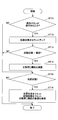
- FIG. 3 is a flowchart of the automatic closing process.
- 4A and 4B are cross-sectional views showing the positional relationship between the upper end portion 2t of the window glass 2 and the upper sash 3, and are cross-sectional views when the plane including the broken line L1 in FIG. 1 is viewed from the direction indicated by the arrow AR1. Correspond.
- the arithmetic unit 6 determines whether or not the automatic closing function is valid (step ST1). For example, the arithmetic device 6 determines that the automatic closing function is valid when the automatic closing function is not restricted by the function restriction unit 64. When the automatic closing function is not prohibited by the function restriction unit 64, it may be determined that the automatic closing function is valid. In other words, even if the automatic closing function is restricted, it may be determined that the automatic closing function is effective if it is not prohibited.
- the opening / closing control unit 60 ends the current automatic closing process without starting the automatic closing function.
- the opening / closing control unit 60 starts the automatic closing function (step ST2). For example, the open / close control unit 60 closes the switch SW2 and the switch SW4 to reversely rotate the electric motor 10 to raise the window glass 2.
- the contact determination unit 62 determines whether or not the window glass 2 is in contact with another object (step ST3). For example, when the torque generated by the electric motor 10 is equal to or greater than the first threshold, the contact determination unit 62 determines that the window glass 2 is in contact with another object.
- step ST3 When it determines with the window glass 2 and the other object not contacting (NO of step ST3), the contact determination part 62 of step ST3 until it determines with the window glass 2 and another object contacting. Repeat the determination.
- the position detection unit 61 determines whether the position of the upper end 2t of the window glass 2 is within the non-detection range. Is determined (step ST4).
- the non-detection range means a range in which an object in contact with the window glass 2 is not detected as a foreign object, that is, a range in which the object in contact with the window glass 2 is regarded as the upper sash 3.
- the “range” is represented by a distance from the fully closed position, for example.
- the position detection unit 61 determines the position of the upper end 2t of the window glass 2 when the distance D1 between the fully closed position and the upper end 2t of the window glass 2 is equal to or less than the threshold value Dt. Is determined to be within the non-detection range.
- the contact determination unit 62 determines that the window glass 2 is in contact with another object, and the position detection unit 61 determines that the position of the upper end 2t of the window glass 2 is within the non-detection range. Then, the arithmetic unit 6 determines that the window 1a is in a fully closed state.
- the contact determination unit 62 determines that the window glass 2 is in contact with another object, and the position detection unit 61 determines that the position of the upper end 2t of the window glass 2 is not within the non-detection range. Then, the arithmetic unit 6 determines that the window glass 2 is in contact with a foreign object other than the upper sash 3.
- the opening / closing control unit 60 determines that the window 1a is fully closed and stops the electric motor 10. (Step ST5). Even if the reverse rotation of the electric motor 10 is continued until the torque generated by the electric motor 10 reaches the second threshold (> first threshold), and the reverse rotation of the electric motor 10 is stopped when the torque reaches the second threshold. Good.
- the position detector 61 resets (initializes) the fully closed position (step ST6).
- the position detection unit 61 sets the current position of the upper end 2t of the window glass 2 as the fully closed position regardless of whether or not the current position of the upper end 2t of the window glass 2 matches the fully closed position. Set.
- the counting unit 63 resets the number of activations. This is because the detection error of the position of the window glass 2 is eliminated by resetting the fully closed position. And the function restriction
- the opening / closing control unit 60 determines that the window glass 2 is in contact with a foreign object other than the upper sash 3. Then, the rotation direction of the electric motor 10 is reversed (step ST7). In the present embodiment, the open / close control unit 60 causes the motor 10 that has been reversely rotated to rotate forward to lower the window glass 2. This is to prevent foreign matter from being caught.
- the opening / closing control unit 60 rotates the motor 10 forward until the window glass 2 reaches the fully open position, and stops the motor 10 when the window glass 2 reaches the fully open position (step ST8).
- the opening / closing control unit 60 may stop the forward rotation of the electric motor 10 when the window glass 2 is lowered by a predetermined distance.
- FIG. 5 is a flowchart of basic processing.
- the arithmetic device 6 repeatedly executes this basic process at a predetermined control cycle.
- the arithmetic unit 6 determines whether or not the operation button 7 has been operated (step ST11). In this embodiment, the arithmetic unit 6 determines that the operation button 7 has been operated when any one of the automatic open button 7A, the manual open button 7B, the automatic close button 7C, and the manual close button 7D is pressed.
- the counting unit 63 counts up the number of activations of the electric motor 10 (step ST12). In this embodiment, the number of activations is incremented by 1 regardless of which of the automatic opening button 7A, the manual opening button 7B, the automatic closing button 7C, and the manual closing button 7D is pressed.
- the function restriction unit 64 determines whether or not the number of activations exceeds the threshold (step ST13). In the present embodiment, the function restriction unit 64 determines whether or not the number of activations exceeds 10.
- the function restriction unit 64 restricts the automatic closing function (step ST14). In this embodiment, the function restriction unit 64 prohibits execution of the automatic closing function.
- step ST13 When it is determined that the number of activations does not exceed the threshold (NO in step ST13), the arithmetic device 6 executes step ST15 without limiting the automatic closing function.
- step ST15 When it is determined that the operation button 7 has not been operated (NO in step ST11), the arithmetic device 6 executes step ST15 without counting up the number of activations and without limiting the automatic closing function.
- step ST15 the arithmetic unit 6 determines whether or not the window 1a is in a fully closed state.
- the arithmetic unit 6 determines whether or not the window 1a is in a fully closed state.
- the window 1a is in the fully closed state. For example, it is determined that the window 1a is in the fully closed state when the position of the upper end 2t reaches the non-detection range by operating the manual close button 7D.
- the position detecting unit 61 When it is determined that the window 1a is in the fully closed state (YES in step ST15), the position detecting unit 61 resets the fully closed position, the counting unit 63 resets the number of activations, and the function limiting unit 64 If the automatic closing function is restricted, the restriction is released (step ST16). In the present embodiment, the position detection unit 61 sets the current position of the upper end 2t of the window glass 2 as a fully closed position. The counting unit 63 resets the number of activations to zero. If the function restriction unit 64 prohibits the execution of the automatic closing function, the function restriction unit 64 cancels the prohibition.
- step ST15 When it is determined that the window 1a is not in the fully closed state (NO in step ST15), the arithmetic device 6 performs any of reset of the fully closed position, reset of the number of activations, and release of the restriction of the automatic closing function. Instead, this basic process is terminated.
- the power window device includes an open / close control unit 60 that performs an automatic closing function that automatically closes the window glass 2, a counting unit 63 that counts the number of activations of the electric motor 10 that drives the window glass 2, and an electric motor. And a function restriction unit 64 that restricts the automatic closing function based on the number of times of activation. Therefore, the automatic closing function can be limited when there is a possibility that the detection error of the position of the window glass 2 has increased. For example, the automatic closing function can be limited when the number of activations of the electric motor 10 exceeds a predetermined threshold. The situation where the number of activations exceeds the threshold value occurs, for example, when an inching operation for slightly moving the window glass 2 is repeated.
- the power window device can reduce the malfunction of the automatic closing function at low cost even if it does not include a sensor (limit switch, hall sensor, etc.) for detecting that the window glass 2 has reached the fully closed position. It can be surely prevented. That is, even in the configuration described later that detects the position of the window glass 2 based on the ripple component of the current Im, it is possible to reliably prevent malfunction of the automatic closing function. Specifically, a situation in which the state in which the window glass 2 has reached the fully closed position is misrecognized as a state in contact with a foreign object, and the window glass 2 is opened by reversing the moving direction of the window glass 2 occurs. Can be prevented. Further, it is possible to prevent a situation in which the state in which the window glass 2 is in contact with the foreign object is misrecognized as a state in which the window glass 2 has reached the fully closed position and the foreign object is sandwiched by the window glass 2.
- a sensor limit switch, hall sensor, etc.
- the function restriction unit 64 may release the restriction of the automatic closing function when the window glass 2 reaches the fully closed position. With this configuration, even when the automatic closing function is temporarily restricted, the power window device releases the restriction and uses the automatic closing function again when the window glass 2 reaches the fully closed position. Can be in a possible state.
- the counting unit 63 may count up the number of activations of the electric motor 10 when the electric motor 10 is activated. For example, the number of activations may be counted up every time the operation button 7 is operated, or the number of activations may be counted up every time the rotation of the electric motor 10 is started regardless of the signal from the operation button 7. Good. With this configuration, the power window device can easily recognize a state in which the detection error of the position of the window glass 2 may have increased.
- the counting unit 63 desirably resets the number of activations of the electric motor 10 to zero when the window glass 2 reaches the fully closed position. This is because when the window glass 2 reaches the fully closed position, the fully closed position is reset, and the detection error of the position of the window glass 2 is eliminated. With this configuration, the counting unit 63 can prevent the automatic closing function from being erroneously restricted early.
- the function restriction unit 64 may prohibit the execution of the automatic closing function when the number of activations of the electric motor 10 exceeds a predetermined threshold.
- the threshold value when prohibiting execution of the automatic closing function may be a value larger than the threshold value when limiting the automatic closing function.
- the rotation angle detector 100 is an example of the position detector 61, detects the rotation angle of the electric motor 10, and detects the position of the window glass 2 based on the rotation angle.
- the rotation angle detector 100 detects the rotation angle of the electric motor 10 based on the voltage V between the terminals of the electric motor 10 and the current Im flowing through the electric motor 10.
- FIG. 7 is a schematic diagram of the commutator 20 in the electric motor 10. As shown in FIG. 7, the commutator 20 is composed of eight commutator pieces 20a separated from each other by slits 20s.
- the slit angle ⁇ c which is the central angle of the arc of each commutator piece 20a, is about 45 degrees.
- the rotation angle detector 100 mainly includes a voltage filter unit 30, a rotation angular velocity calculation unit 31, a rotation angle calculation unit 32, a current filter unit 33, a first signal generation unit 34, a second signal generation unit 35, and a rotation information calculation unit. 36, elements such as a resistance setting unit 37 are included. Each element may be configured by an electric circuit or may be configured by software.
- the voltage filter unit 30 smoothes the waveform of the inter-terminal voltage V output from the voltage detection unit 10a.
- the voltage filter unit 30 smoothes the waveform of the voltage V between the terminals so that the rotation angular velocity calculation unit 31 can accurately calculate the rotation angular velocity of the electric motor 10.
- the voltage filter unit 30 is a low-pass filter, and outputs an inter-terminal voltage V ′ from which a high-frequency component in the waveform of the inter-terminal voltage V output by the voltage detection unit 10 a is removed as noise.
- the rotation angular velocity calculation unit 31 calculates the rotation angular velocity of the electric motor 10 based on the voltage V ′ between the terminals of the electric motor 10 and the current Im flowing through the electric motor 10. In the example of FIG. 6, the rotational angular velocity calculation unit 31 calculates the rotational angular velocity ⁇ based on Expression (1).
- Ke is a back electromotive force constant
- Rm is a value (set resistance value) corresponding to the internal resistance of the electric motor 10
- Lm is an inductance of the electric motor 10
- dIm / dt is a single derivative of the current Im.
- the single differentiation of the current Im is, for example, the difference between the previous value of the current Im and the current value of the current Im.
- the set resistance value Rm is set by the resistance setting unit 37 when the rotation angle detector 100 is activated, for example.
- the rotation angular velocity calculation unit 31 calculates the rotation angular velocity ⁇ of the electric motor 10 at a constant control cycle, and outputs the calculated rotation angular velocity ⁇ to the rotation angle calculation unit 32.
- the rotation angle calculation unit 32 calculates the rotation angle ⁇ of the electric motor 10.
- the rotation angle calculation unit 32 calculates the rotation angle ⁇ based on Expression (2).
- the rotation angle calculation unit 32 calculates the rotation angle ⁇ by accumulating the rotation angular velocity ⁇ output by the rotation angular velocity calculation unit 31 at every constant control cycle, and outputs a rotation angle signal that is a signal related to the calculated rotation angle ⁇ . Output to the second signal generator 35.
- the rotation angle calculation unit 32 resets the rotation angle ⁇ to zero according to the synchronization command from the second signal generation unit 35.
- the current filter unit 33 outputs a ripple component Ir that is a specific frequency component included in the current Im output from the current detection unit 10b.
- the current filter unit 33 is configured by, for example, a bandpass filter that passes the frequency of the ripple component Ir so that the first signal generation unit 34 can detect the ripple component Ir of the current Im.
- the current filter unit 33 configured by a band-pass filter removes frequency components other than the ripple component Ir from the waveform of the current Im output from the current detection unit 10b.
- the ripple component Ir used in the present embodiment is generated due to contact / separation between the commutator piece 20a and the brush. Therefore, the angle at which the electric motor 10 rotates during one cycle of the ripple component Ir is equal to the slit-to-slit angle ⁇ c.
- the first signal generation unit 34 generates a signal estimated from the waveform of the ripple component Ir that the electric motor 10 has rotated by a certain angle.
- This signal is a signal corresponding to the period of the ripple component Ir.
- the fixed angle may be an angle corresponding to one cycle of the ripple component Ir or an angle corresponding to a half cycle.
- a signal (first pulse signal Pa) estimated from the waveform of the ripple component Ir is generated.
- the first signal generation unit 34 generates the first pulse signal Pa based on the waveform of the ripple component Ir output from the current filter unit 33.
- FIG. 8A is a diagram illustrating an example of timing at which the first signal generation unit 34 generates the first pulse signal Pa.
- the first signal generator 34 generates a first pulse signal Pa for each cycle of the ripple component Ir.
- the first pulse signal Pa is generated every time the ripple component Ir exceeds the reference current value Ib.
- the first pulse signal Pa is generated at times t1, t2, t3,. C1, C2, C3,..., Cn, etc. indicate the period of the ripple component Ir, and ⁇ 1, ⁇ 2, ⁇ 3,..., ⁇ n, etc., are generated by the first signal generator 34 for the first pulse signal.
- the rotation angle ⁇ is a value calculated by the rotation angle calculation unit 32.
- the first signal generator 34 typically generates the first pulse signal Pa every time the rotation angle ⁇ increases by the inter-slit angle ⁇ c.
- the first signal generator 34 cannot detect the ripple component Ir and detect the first pulse signal Pa, for example, when the current Im and its ripple component Ir become small during the inertia rotation period after the motor 10 is powered off. May not be generated.
- the first signal generation unit 34 may erroneously generate the first pulse signal Pa according to the inrush current. Such generation omission or erroneous generation of the first pulse signal Pa reduces the reliability of information related to the rotation of the electric motor 10 output by the rotation angle detector 100 (hereinafter referred to as “rotation information”).
- the second signal generation unit 35 can generate a signal representing the rotation angle of the electric motor 10 with higher accuracy.
- the second signal generation unit 35 generates a signal indicating that the electric motor 10 has rotated by a predetermined angle. For example, the second signal generation unit 35 generates the second pulse signal for each inter-slit angle ⁇ c based on the rotation angle signal output from the rotation angle calculation unit 32 and the first pulse signal Pa output from the first signal generation unit 34. Pb is generated.
- the second pulse signal Pb is an example of information indicating that the electric motor 10 has rotated by a predetermined angle. Since the first pulse signal Pa is a signal estimated from only the waveform of the ripple component Ir, it may be erroneously output. On the other hand, since the second pulse signal Pb is a signal estimated from both the first pulse signal Pa and the rotation angle signal, the error can be reduced to a certain value or less.
- FIG. 9 is a diagram illustrating an example of timing at which the second signal generation unit 35 generates the second pulse signal Pb.
- the first threshold ⁇ u and the second threshold ⁇ d are thresholds for accepting the first pulse signal Pa, and are set based on, for example, the maximum phase difference between the rotation angle ⁇ and the actual rotation angle of the electric motor 10.
- the second signal generator 35 generates a second pulse based on the first pulse signal Pa generated first by the first signal generator 34 when the rotation angle ⁇ is not less than the first threshold ⁇ u and less than the slit angle ⁇ c.
- a signal Pb is generated.
- the first threshold value ⁇ u may be a preset value or a dynamically set value.
- FIG. 9 shows a reception range, which is an angle range in which the rotation angle ⁇ is greater than or equal to the first threshold ⁇ u and less than the inter-slit angle ⁇ c, as a dot pattern. In the example of FIG.
- the rotation angles ⁇ 1, ⁇ 2, and ⁇ 5 when the first signal generation unit 34 generates the first pulse signals Pa1, Pa2, and Pa4 are equal to or greater than the first threshold ⁇ u and less than the inter-slit angle ⁇ c. That is, the remaining angles until each of the rotation angles ⁇ 1, ⁇ 2, and ⁇ 5 reaches the inter-slit angle ⁇ c is less than the angle ⁇ .
- the angle ⁇ is set based on the maximum error between the rotation angle ⁇ and the actual rotation angle of the electric motor 10.
- the second signal generation unit 35 regards the first pulse signals Pa1, Pa2, and Pa4 generated by the first signal generation unit 34 at times t1, t2, and t5 as not noise.
- the second signal generator 35 generates the second pulse signals Pb1, Pb2, and Pb4 at times t1, t2, and t5.
- the second signal generator 35 outputs a synchronization command to the rotation angle calculator 32. If noise having the same frequency component as the ripple component Ir occurs when the rotation angle ⁇ is less than the slit-to-slit angle ⁇ c and greater than or equal to the first threshold value ⁇ u, an erroneous first pulse signal Pa is output, and the second There is a possibility that the pulse signal Pb is generated.
- the true ripple component Ir is detected at the next timing, and the rotation angle detector 100 can detect the correct rotation angle. Therefore, the rotation angle detected by the rotation angle detector 100 returns to the correct rotation angle even if it is temporarily detected by noise due to noise. Further, the error range is less than the angle ⁇ , and there is no practical problem.
- the second signal generation unit 35 generates the second pulse signal Pb when the rotation angle ⁇ reaches a predetermined angle.
- the predetermined angle is, for example, the slit-to-slit angle ⁇ c.
- the rotation angle ⁇ is an angle calculated by the rotation angle calculation unit 32 and includes an error.
- the second pulse signals Pb3, Pb5, and Pb6 are generated when the absolute values of the rotation angles ⁇ 3, ⁇ 7, and ⁇ 9 reach the inter-slit angle ⁇ c at times t3, t7, and t9.
- the second signal generator 35 outputs a synchronization command to the rotation angle calculator 32.
- the rotation angle calculation unit 32 resets the rotation angle ⁇ to zero.
- the second signal generation unit 35 generates the second pulse signal Pb2 and then does not receive the first pulse signal Pa, so that the absolute value of the rotation angle ⁇ is the slit-to-slit angle.
- the second pulse signal Pb3 is generated.
- the second signal generation unit 35 determines that the absolute value of the rotation angle ⁇ calculated by the rotation angle calculation unit 32 is the angle between the slits. As long as ⁇ c is reached, the second pulse signal Pb is generated. Therefore, generation omission of the first pulse signal Pa can be reliably prevented.
- the second signal generator 35 does not generate the second pulse signal Pb when the rotation angle ⁇ when the first signal generator 34 generates the first pulse signal Pa is less than the second threshold ⁇ d.
- the second threshold value ⁇ d may be a preset value or a dynamically set value. Such a situation typically occurs after the second pulse signal Pb is generated due to the rotation angle ⁇ reaching a predetermined angle.
- FIG. 9 shows a reception range, which is an angle range in which the rotation angle ⁇ is greater than or equal to zero and less than the second threshold value ⁇ d, with a dot pattern. In the example of FIG.
- the first signal generation unit 34 performs the first pulse.
- a signal Pa3 is generated.
- the rotation angle ⁇ 4 at this time is less than the second threshold value ⁇ d. That is, the rotation angle ⁇ 4 integrated after being reset at time t3 is still less than the angle ⁇ .
- the second signal generation unit 35 can determine that the first pulse signal Pa3 generated by the first signal generation unit 34 at time t4 can be integrated with the second pulse signal Pb3 generated at time t3.
- the second pulse signal Pb3 is generated because the rotation angle ⁇ calculated by the rotation angle calculation unit 32 has reached the inter-slit angle ⁇ c even though the actual rotation angle has not reached the inter-slit angle ⁇ c. Occurs when.
- the time when the first pulse signal Pa3 is generated immediately after the generation of the second pulse signal Pb3 is the moment when the actual rotation angle reaches the inter-slit angle ⁇ c. For this reason, the second signal generation unit 35 outputs a synchronization command to the rotation angle calculation unit 32 when the first pulse signal Pa3 is generated.
- the second signal generator 35 does not generate the second pulse signal Pb at time t4.
- a broken-line arrow toward “x” in FIG. 9 indicates that the second pulse signal Pb is not generated based on the first pulse signal Pa3. The same applies to the broken-line arrow toward “X” in the other drawings.
- the first signal generation unit 34 may generate the first pulse signal Pa continuously in a short time. As described above, in FIG. 8A, the first signal generator 34 generates the first pulse signal Pa every time the ripple component Ir exceeds the reference current value Ib. Immediately before and immediately after the ripple component Ir exceeds the reference current value Ib, the first pulse signal Pa is erroneously generated even if minute noise is superimposed. In this case, the interval at which the first signal generator 34 generates the first pulse signal Pa is less than the angle ⁇ (second threshold ⁇ d). In the example of FIG. 9, the first signal generation unit 34 generates the first pulse signal Pa2 at time t2. The second signal generator 35 generates the second pulse signal Pb2 and outputs a synchronization command to the rotation angle calculator 32.
- the rotation angle calculation unit 32 resets the rotation angle ⁇ . Thereafter, the first signal generator 34 generates the first pulse signal Pa2 ′ at time t2 ′. The rotation angle ⁇ at time t2 ′ is less than the second threshold value ⁇ d. In this case, the second signal generator 35 does not generate the second pulse signal Pb and does not output a synchronization command.
- a broken-line arrow toward “x” in FIG. 9 indicates that the second pulse signal Pb is not generated based on the first pulse signal Pa3.
- the ripple component Ir exceeds the reference current value Ib, when a minute noise is superimposed, any of the first pulse signals Pa generated continuously in a short time reaches the inter-slit angle ⁇ c.
- the rotation angle ⁇ reached the inter-slit angle ⁇ c at the time of the first first pulse signal Pa. Even if it is considered, there is no problem in practical use. Further, even if the same noise occurs every time the ripple component Ir exceeds the reference current value Ib, the error is suppressed to less than the angle ⁇ . That is, no error is accumulated. For this reason, it is possible to suppress the error within a range where there is no practical problem.
- the second signal generation unit 35 is configured so that the rotation angle ⁇ when the first signal generation unit 34 generates the first pulse signal Pa is greater than or equal to the second threshold ⁇ d and less than the first threshold ⁇ u, that is, the rotation angle.
- ⁇ is within the angle range R1
- the second pulse signal Pb is not generated, and a synchronization command is not output to the rotation angle calculation unit 32.
- the rotation angle ⁇ 6 when the first signal generation unit 34 generates the first pulse signal Pa5 at time t6 is equal to or greater than the second threshold ⁇ d and less than the first threshold ⁇ u.
- the second signal generation unit 35 can determine that the first pulse signal Pa5 is based on noise. Therefore, the second signal generation unit 35 does not generate the second pulse signal Pb at time t6 and does not output a synchronization command to the rotation angle calculation unit 32. That is, the influence of the first pulse signal Pa5 based on noise can be eliminated.
- the second signal generator 35 does not generate the second pulse signal Pb when the rotation angle ⁇ when the first signal generator 34 generates the first pulse signal Pa is less than the second threshold ⁇ d. However, when the rotation angle ⁇ when the first signal generation unit 34 generates the first pulse signal Pa is less than the second threshold ⁇ d, the second signal generation unit 35 issues a synchronization command to the rotation angle calculation unit 32. There are cases where it is output and there is a case where a synchronization command is not output.
- the two-signal generation unit 35 sends a synchronization command to the rotation angle calculation unit 32.
- a plurality of first pulse signals Pa are generated when the rotation angle ⁇ is less than the second threshold ⁇ d. Then, the second and subsequent first pulse signals Pa are ignored. That is, the second signal generator 35 does not output a synchronization command.
- the second pulse signal Pa is generated.
- the signal generator 35 does not output a synchronization command. That is, when a plurality of first pulse signals Pa are generated while the first pulse signal Pa is less than the second threshold ⁇ d (angle ⁇ ), the second and subsequent first pulse signals Pa are ignored. That is, the second signal generator 35 does not output a synchronization command.
- the rotation angle ⁇ 4 ′ when the first signal generator 34 generates the first pulse signal Pa3 ′ at time t4 ′ is less than the second threshold ⁇ d.
- the first pulse signal Pa3 ′ is the second first pulse signal Pa after the most recent second pulse signal Pb3 is generated. Therefore, when receiving the first pulse signal Pa3 ′, the second signal generation unit 35 does not generate the second pulse signal Pb and does not output a synchronization command to the rotation angle calculation unit 32.
- the rotation angle detector 100 can suppress the detection error of the rotation angle ⁇ of the electric motor 10 within a practically acceptable range. In particular, the rotation angle detector 100 does not accumulate errors. For this reason, regardless of the rotation speed of the electric motor 10, the error can be suppressed within a certain range.
- the inventor discovered that the following premise is satisfied, and invented the rotation angle detector 100 described above. (1) The erroneous detection of the ripple component Ir due to minute noise is limited to just before or immediately after the ripple component Ir exceeds the reference current value Ib. In this case, the erroneous first pulse signal Pa is generated only for a short time before and after the correctly generated first pulse signal Pa (from before the angle ⁇ to after the angle ⁇ ).
- the second signal generation unit 35 reduces the current Im and its ripple component Ir during the inertia rotation period after the power of the motor 10 is turned off, and the first signal generation unit 34 has a waveform of the ripple component Ir. Even if the first pulse signal Pa cannot be generated based on the second pulse signal Pb, the second pulse signal Pb can be generated.
- the second signal generation unit 35 for example, generates an inrush current immediately after the motor 10 is turned on, and the first signal generation unit 34 erroneously generates the first pulse signal Pa according to the inrush current. Even in this case, the second pulse signal Pb corresponding to the first pulse signal Pa is not generated. That is, the influence of the first pulse signal Pa can be eliminated.
- the second signal generation unit 35 generates the first pulse signal Pa even if the first signal generation unit 34 erroneously generates the first pulse signal Pa due to noise or the like.
- the corresponding second pulse signal Pb is not generated, and a synchronization command is not output to the rotation angle calculation unit 32.
- the rotation angle detector 100 calculates the rotation information of the motor 10 based on the second pulse signal Pb generated based on both the first pulse signal Pa and the rotation angle signal. Reliability can be improved.
- the second signal generator 35 outputs a direction signal indicating the rotation direction of the electric motor 10.
- the second signal generation unit 35 outputs a positive value as the rotation angle ⁇ if the rotation direction is the forward rotation direction, and outputs a negative value as the rotation angle ⁇ if the rotation direction is the reverse rotation direction.
- the rotation angle ⁇ has a positive value when the current flowing through the electric motor 10 is a positive value, and has a negative value when the current flowing through the electric motor 10 is a negative value.
- the rotation angle ⁇ has a positive value when the current flowing through the electric motor 10 has a negative value, and has a negative value when the current flowing through the electric motor 10 has a positive value.
- the rotation information calculation unit 36 calculates rotation information of the electric motor 10.
- the rotation information of the electric motor 10 includes, for example, the rotation amount (rotation angle) from the reference rotation position, the rotation number from the reference rotation position, the relative position of the upper end 2t of the window glass 2 with respect to the reference position (fully closed position), and the window 1a. It may be a value converted into an opening amount of. Moreover, statistical values such as an average value, a maximum value, a minimum value, and a median value of the rotation angular velocity ⁇ in a certain period may be included. In the example of FIG. 6, the rotation information calculation unit 36 calculates rotation information of the electric motor 10 based on the output of the second signal generation unit 35.
- the amount of rotation after the rotation of the electric motor 10 is calculated by multiplying the number of second pulse signals Pb generated after the rotation of the electric motor 10 is multiplied by the inter-slit angle ⁇ c.
- the rotation information calculation unit 36 determines whether to increment or decrement the number of second pulse signals Pb based on the direction signal output together with the second pulse signal Pb by the second signal generation unit 35.
- the rotation information calculation unit 36 separately counts the number of second pulse signals Pb received together with the direction signal representing the forward rotation direction and the number of second pulse signals Pb received together with the direction signal representing the reverse rotation direction. Then, the rotation amount of the electric motor 10 may be calculated based on the difference between them.
- the resistance setting unit 37 sets a resistance value corresponding to the resistance characteristic of the electric motor 10. For example, when the rotation angle detector 100 is activated, the resistance setting unit 37 sets a value stored in advance in the nonvolatile storage medium as the set resistance value Rm in Expression (1).
- the set resistance value Rm may be updated dynamically.
- FIG. 10 is a flowchart of the rotation amount calculation process.
- the rotation angle detector 100 performs this rotation amount calculation process while the electric motor 10 is being driven.
- the rotation angle detector 100 acquires the inter-terminal voltage V and the current Im (step ST21).
- the rotation angle detector 100 acquires the inter-terminal voltage V output from the voltage detection unit 10a and the current Im output from the current detection unit 10b for each predetermined control cycle.
- the rotation angle detector 100 calculates the rotation angular velocity ⁇ and the rotation angle ⁇ (step ST22).
- the rotational angular velocity calculation unit 31 of the rotational angle detector 100 calculates the rotational angular velocity ⁇ for each predetermined control cycle by substituting the inter-terminal voltage V ′ and the current Im into the equation (1).
- the rotation angle calculation unit 32 of the rotation angle detector 100 calculates the rotation angle ⁇ by integrating the rotation angular velocities ⁇ calculated for each control cycle.
- the rotation angle detector 100 determines whether or not the rotation angle ⁇ is less than a predetermined angle (step ST23).
- the second signal generation unit 35 of the rotation angle detector 100 determines whether or not the rotation angle ⁇ is less than the inter-slit angle ⁇ c.
- the second signal generation unit 35 determines that the first pulse signal Pa has not been generated at the timing up to the inter-slit angle ⁇ c. . In this case, the second signal generation unit 35 sets the flag F to “False” to indicate that the first pulse signal Pa is not generated (step ST23A).
- the flag F is a flag for indicating whether or not the first pulse signal Pa is generated. The initial value of the flag F is “False” indicating that the first pulse signal Pa is not generated. The flag F being “True” indicates that the first pulse signal Pa has already been generated.
- the second pulse signal Pb is generated (step ST29), and the rotation angle ⁇ is reset to zero (step ST30).
- the rotation angle ⁇ is the rotation angles ⁇ 3, ⁇ 7 at the times t3, t7, t9. , ⁇ 9 is reached.
- the second signal generator 35 determines whether or not the first pulse signal Pa is generated (step ST24). . In the example of FIG. 6, it is determined whether the first pulse signal Pa is generated by the first signal generation unit 34.
- the rotation angle is detected.
- the device 100 calculates the rotation amount (step ST27).
- the rotation information calculation unit 36 calculates the rotation amount of the electric motor 10 based on the output of the second signal generation unit 35. In this case, there is no change in the calculated rotation amount. This corresponds to the case where the rotation angle ⁇ is the rotation angle ⁇ 0 at time t0 in the example of FIG.
- the rotation angle detector 100 determines whether or not the rotation angular velocity ⁇ has become zero (step ST28). When the rotation angle detector 100 determines that the rotation angular velocity ⁇ is not zero (NO in step ST28), the process returns to step ST1, and when it is determined that the rotation angular velocity ⁇ has become zero (step ST28). YES), the rotation amount calculation process is terminated.
- the second signal generation unit 35 determines whether or not the rotation angle ⁇ is less than the first threshold ⁇ u (step ST25). This is because the first pulse signal Pa generated at a timing less than the first threshold ⁇ u is highly likely to be based on noise.
- the second signal generator 35 sets the flag F to “True” to indicate whether or not the first pulse signal Pa has been generated. (Step ST25A). Then, the second signal generator 35 generates the second pulse signal Pb (step ST29), and resets the rotation angle ⁇ to zero (step ST30). This is because when the first pulse signal Pa is generated when the rotation angle ⁇ is equal to or greater than the first threshold ⁇ u, the actual rotation angle at the time when the first pulse signal Pa is generated is close to the inter-slit angle ⁇ c. This corresponds to the case where the first pulse signals Pa1, Pa2, Pa4 are generated at times t1, t2, t5 in the example of FIG.
- the second signal generator 35 cannot determine at this time that the first pulse signal Pa is not based on noise.
- the rotation angle ⁇ may include some error.
- the generation timing of the first pulse signal Pa may be slightly shifted due to noise or the like. For this reason, the time when the rotation angle ⁇ reaches the slit-to-slit angle ⁇ c may be different from the time when the first pulse signal Pa is generated. For this reason, it is because it is not known which is earlier, the time when the rotation angle ⁇ reaches the inter-slit angle ⁇ c or the time when the first pulse signal Pa is generated. Therefore, the second signal generator 35 determines whether or not the rotation angle ⁇ is less than the second threshold ⁇ d with respect to the first pulse signal Pa received first after generating the latest second pulse signal Pb. (Step ST26).
- the second signal generator 35 checks the flag F (step ST26A).
- the flag F is a flag for determining that the first pulse signal Pa is continuously generated.
- the flag F is “True”
- the first pulse signal Pa is the second and subsequent first pulse signals Pa generated continuously.
- the rotation angle detector 100 calculates the rotation amount (step ST27). This corresponds to the case where the first pulse signals Pa2 ′ and Pa3 ′ are generated at times t2 ′ and t4 ′ in the example of FIG.
- the second signal generation unit 35 sets the flag F to “True” (step ST26B). Thereafter, the second signal generation unit 35 resets the rotation angle ⁇ to zero (step ST30). This is because when the rotation angle ⁇ is less than the second threshold ⁇ d, the actual rotation angle when the first pulse signal Pa is generated is close to the inter-slit angle ⁇ c. That is, when it is less than the second threshold ⁇ d, it can be determined that the first pulse signal Pa corresponds to the second pulse signal Pb generated immediately before. This corresponds to the case where the first pulse signals Pa3 and Pa6 are generated at times t4 and t8 in the example of FIG. That is, it can be determined that the first pulse signals Pa3 and Pa6 correspond to the second pulse signals Pb3 and Pb5.
- the second signal generation unit 35 When it is determined that the rotation angle ⁇ related to the first first pulse signal Pa is equal to or greater than the second threshold ⁇ d (NO in step ST26), that is, when it is determined that the rotation angle ⁇ is within the angle range R1, the second signal generation unit 35 Then, it is determined that the first pulse signal Pa is based on noise. In this case, the second signal generator 35 does not generate the second pulse signal Pb and does not reset the rotation angle ⁇ . Then, the rotation information calculation unit 36 calculates the rotation amount of the electric motor 10 based on the output of the second signal generation unit 35. This corresponds to the case where the first pulse signal Pa5 is generated at time t6 in the example of FIG. That is, the second signal generation unit 35 determines that the first pulse signal Pa5 is based on noise.
- the rotation angle detector 100 calculates the rotation amount of the electric motor 10 (step ST27).
- the rotation information calculation unit 36 of the rotation angle detector 100 multiplies the number of second pulse signals Pb generated after the rotation of the electric motor 10 is multiplied by the inter-slit angle ⁇ c. The amount of rotation after the start of rotation is calculated.
- FIG. 11 is a diagram showing transitions of the composite pulse signal and the hall pulse signal.
- the synthesized pulse signal is a signal obtained by synthesizing a plurality of pulses of the second pulse signal Pb into one pulse.
- the slit-to-slit angle ⁇ c is 90 degrees.
- the first pulse signal Pa and the second pulse signal Pb are basically generated every time the rotating shaft of the electric motor 10 rotates 90 degrees.
- the synthesized pulse signal is generated by synthesizing two pulses of the second pulse signal Pb into one pulse. That is, the rotation angle detector 100 is configured to generate one composite pulse signal each time the rotation shaft of the electric motor 10 rotates 180 degrees.
- the hall pulse signal is a pulse signal output from the hall sensor.
- the hall sensor detects a magnetic flux generated by a magnet attached to the rotating shaft of the electric motor 10 for comparison between the second pulse signal Pb and the hall pulse signal.
- the rotation angle detector 100 is configured to generate one Hall pulse signal each time the rotation shaft of the electric motor 10 rotates 180 degrees.
- FIG. 12 is a flowchart of the update process.
- the resistance setting unit 37 repeatedly executes this update process at a predetermined control cycle.
- the resistance setting unit 37 determines whether or not the rotation of the electric motor 10 is stable (step ST31).
- the rotation stable state for example, the fluctuation range of the voltage V between the terminals of the electric motor 10 in a predetermined period is less than a predetermined value, and the fluctuation width of the current Im flowing in the electric motor 10 in the predetermined period is less than a predetermined value.
- FIG. 13 shows an example of a rotationally stable state of the electric motor 10 used for raising and lowering the window glass 2. Specifically, the temporal transition of the voltage V between terminals, the current Im, and the first pulse signal Pa when an inching operation for lowering the window glass 2 is performed is shown.
- the inching operation for lowering the window glass 2 is, for example, a short time pressing operation of the manual close button 7D.
- FIG. 13 shows how the switches SW1 and SW3 (see FIG. 6) are closed when the manual close button 7D is pressed at time t1, and the inter-terminal voltage V and current Im increase.
- the switch SW1 is opened and the switch SW2 (see FIG.
- FIG. 14 shows temporal transitions of the inter-terminal voltage V, the current Im, and the first pulse signal Pa in the first rotation stable state.
- each time the resistance setting unit 37 detects a predetermined number of first pulse signals Pa the resistance setting unit 37 calculates the average values of the inter-terminal voltage V and the current Im during that period. Other statistical values such as a median value, a mode value, a maximum value, and a minimum value may be used.
- the average values of the inter-terminal voltage V and current Im in the period T are calculated.
- Periods T1, T2, T3,..., Tn represent periods required to detect the eight first pulse signals Pa.
- the average terminal voltages V1, V2, V3,..., Vn represent the average value of the terminal voltages V in the periods T1, T2, T3,.
- the average currents Im1, Im2, Im3,..., Imn represent average values of the current Im in the periods T1, T2, T3,.
- the resistance setting unit 37 determines that the electric motor 10 is in a rotationally stable state when, for example, the following conditions are satisfied.
- ⁇ T represents a period threshold
- ⁇ Im represents a current threshold
- ⁇ V represents a voltage threshold
- i represents an integer of 1 to n.
- the resistance setting unit 37 has an absolute value of a difference between each of the periods T1 to Tn with respect to each period T1 smaller than the period threshold value ⁇ T, and an absolute value of the difference between the average currents Im1 to Imn with respect to each average current Im1
- the absolute value of the difference between the average inter-terminal voltages V1 to Vn with respect to the average inter-terminal voltage V1 is smaller than the threshold value ⁇ Im and smaller than the voltage threshold value ⁇ V
- the electric motor 10 is in a rotationally stable state. That is, when the generation interval of the first pulse signal Pa, the current Im, and the inter-terminal voltage V are all stable, it is determined that the electric motor 10 is in a rotation stable state.
- the dot pattern area in FIG. 14 represents a range of T1 ⁇ ⁇ T.
- the illustration by the alternate long and short dash line in FIG. 14 indicates that the absolute value of the difference between the average terminal voltages V2, V3, and Vn with respect to the average terminal voltage V1 is smaller than the voltage threshold value ⁇ V.
- the illustration by the two-dot chain line in FIG. 14 represents that the absolute value of the difference between the average currents Im2, Im3, Imn with respect to the average current Im1 is smaller than the current threshold value ⁇ Im.
- the resistance setting unit 37 can determine that the electric motor 10 was in a rotationally stable state during a period from time t2 to time t3 at time t3. That is, it can be determined that the electric motor 10 is in a rotationally stable state at the present time.
- the resistance setting unit 37 calculates the rotation angular velocity ⁇ ′ based on the cycle of the first pulse signal Pa (step ST32). For example, the resistance setting unit 37 calculates the rotational angular velocity ⁇ ′ based on the following equation (3).
- n represents the number of periods T
- M represents the number of first pulse signals Pa in the period T.
- the rotational angular velocity ⁇ ′ represents an average rotational angular velocity [rad / s] while the motor 10 is rotated 10 times.
- the resistance setting unit 37 can calculate the rotational angular velocity ⁇ ′ based on the period of the first pulse signal Pa (80 periods in the above example).
- the resistance setting unit 37 calculates an estimated resistance value R′m based on the rotational angular velocity ⁇ ′ (step ST33). For example, the resistance setting unit 37 calculates an estimated resistance value R′m based on the following equation (4).
- Equation (4) is a basic theoretical equation of the motor, Ke represents a back electromotive force constant, and Ke ⁇ ⁇ ′ represents a back electromotive force estimated value. That is, a value obtained by subtracting the estimated back electromotive force value from the average value of the average terminal voltages V1 to Vn by the average value of the average currents Im1 to Imn is derived as the estimated resistance value R′m.
- the average value may be another statistical value such as a median value, a mode value, a maximum value, or a minimum value.
- the resistance setting unit 37 determines whether or not the estimated resistance value R′m is within the normal range (step ST34).
- the resistance setting unit 37 refers to the upper limit and the lower limit of the normal range registered in advance in the nonvolatile storage medium, and determines whether or not the estimated resistance value R′m is within the normal range.
- At least one of the upper limit and the lower limit of the normal range may be dynamically changed according to the outside air temperature, the temperature of the electric motor 10, and the like.
- the resistance setting unit 37 updates the set resistance value Rm using the estimated resistance value R′m (step ST35).
- the resistance setting unit 37 updates the set resistance value Rm using the estimated resistance value R′m in the same cycle as that for calculating the estimated resistance value R′m.
- the resistance setting unit 37 may update the set resistance value Rm at a cycle different from the cycle for calculating the estimated resistance value R′m.
- the set resistance value Rm may be updated at a cycle shorter than the cycle for calculating the estimated resistance value R′m.
- the resistance setting unit 37 may update the set resistance value Rm with, for example, the resistance value R ′′ m derived by the following equation (5).
- Km represents a positive real constant of 1.0 or less. That is, as the value of Km is closer to 1.0, the set resistance value Rm is updated with a resistance value R ′′ m that is closer to the estimated resistance value R′m. Typically, Km is less than 1.0. This is to prevent sudden changes in the set resistance value Rm, vibration, etc.
- Km may be a fixed value or a variable value registered in advance in the nonvolatile storage medium, and is a value that is dynamically calculated and set. For example, the Km when an inching operation (a relatively short pressing operation) is performed is set to be larger than the Km when a normal operation (a relatively long pressing operation) is performed. This is because when the inching operation is performed, the time available for repeatedly executing the process of updating the set resistance value Rm is shorter than when the inching operation is performed.
- the resistance setting unit 37 determines that the difference between the updated set resistance value Rm (resistance value R ′′ m) and the estimated resistance value R′m is the set resistance value before update.
- the set resistance value Rm is updated so as to be smaller than the difference between Rm and the estimated resistance value R′m, and the set resistance value Rm is gradually brought closer to the estimated resistance value R′m while preventing a sudden change in the set resistance value Rm.
- the resistance setting unit 37 gradually changes the set resistance value Rm to the estimated resistance value R′m.
- the resistance setting unit 37 is configured to calculate the estimated resistance value R′m before the new estimated resistance value R′m is calculated.
- the set resistance value Rm can be gradually brought closer to the estimated resistance value R′m. That.
- the resistance R "m is to approach the estimated resistance value R'm whenever derived.
- the resistance setting unit 37 When it is determined that the electric motor 10 is not in the rotation stable state (NO in step ST31) or when it is determined that the estimated resistance value R′m is not within the normal range (NO in step ST34), the resistance setting unit 37 The current update process is terminated without updating the set resistance value Rm. In this case, the rotation angular velocity calculation unit 31 calculates the rotation angular velocity ⁇ based on Expression (1) using the current set resistance value Rm.
- the resistance setting unit 37 calculates the rotational angular velocity ⁇ ′ of the electric motor 10 from the cycle of the first pulse signal Pa when the electric motor 10 is in the rotation stable state. Then, the estimated resistance value R′m can be derived based on the calculated rotational angular velocity ⁇ ′, and the set resistance value Rm in the equation (1) can be updated using the estimated resistance value R′m. Therefore, the set resistance value Rm can be appropriately updated in accordance with the change in resistance characteristics of the electric motor 10 due to the temperature change, aging change, etc. of the electric motor 10.
- the secular change includes, for example, commutator piece 20a wear, brush wear, and the like.
- the rotation angle detector 100 for example, the current Im and its ripple component Ir become small in the inertial rotation period after the power of the motor 10 is turned off, and the first signal generation unit 34 determines the first based on the waveform of the ripple component Ir.
- the 1-pulse signal Pa cannot be generated, information related to the rotation of the electric motor 10 can be acquired with higher reliability.
- the second pulse signal Pb is more accurately generated based on the rotation angular velocity ⁇ and the rotation angle ⁇ calculated in real time using an appropriate set resistance value Rm, regardless of the first pulse signal Pa.
- the information regarding rotation of the electric motor 10 can be acquired with higher reliability. For example, regarding the electric motor 10 used for raising and lowering the window glass 2, even when the inching operation for raising and lowering the window glass 2 is performed, more information on the rotation of the electric motor 10 is obtained. Acquired with high reliability.
- the rotation angle detector 100 that acquires the rotation information of the electric motor 10 including the commutator 20 is detected by the resistance setting unit 37 that sets a resistance value corresponding to the resistance characteristic of the electric motor 10 and the voltage detection unit 10a.
- a rotation information calculation unit 36 that calculates information related to rotation of the electric motor 10 based on the detected voltage value, the detection current value detected by the current detection unit 10b, and the set resistance value Rm set by the resistance setting unit 37. Then, the resistance setting unit 37 derives the estimated resistance value R′m in real time based on the detected voltage value and the detected current value detected in the rotation stable state in which the rotation of the electric motor 10 is stable, and the estimated resistance value The set resistance value Rm is updated in real time using R′m.
- the rotation information of the electric motor 10 can be acquired with high reliability. This means that parts necessary for using a rotation sensor such as a sensor interface circuit and a harness can be omitted. Therefore, weight reduction, cost reduction, size reduction, etc. can be realized.
- the resistance setting unit 37 updates the set resistance value Rm using the estimated resistance value R′m, and the estimated resistance value R′m is outside the predetermined range. In such a case, the set resistance value Rm is not updated. Therefore, it is possible to prevent the set resistance value Rm from being updated by an abnormal estimated resistance value R′m.
- the rotation stable state for example, the fluctuation width of the inter-terminal voltage V in a predetermined period is less than a predetermined value, the fluctuation width of the current Im in the predetermined period is less than a predetermined value, and the first pulse signal in the predetermined period This is a state where the fluctuation range of the period of Pa is less than a predetermined value.
- the rotation stable state may be another state determined using at least one of the voltage V between terminals, the current Im, and the cycle of the first pulse signal Pa.
- the standard deviation of the inter-terminal voltage V in a predetermined period is less than a predetermined value
- the standard deviation of the current Im in the predetermined period is less than a predetermined value
- the standard of the cycle of the first pulse signal Pa in the predetermined period may be less than a predetermined value
- the integrated value of the inter-terminal voltage V in a predetermined period may be in a predetermined range
- the integrated value of the current Im in the predetermined period may be in a predetermined range.
- the resistance setting unit 37 desirably has a difference between the set resistance value Rm after update and the estimated resistance value R′m smaller than the difference between the set resistance value Rm before update and the estimated resistance value R′m.
- the set resistance value Rm is configured to be updated. This is to make the set resistance value Rm gradually approach the estimated resistance value R′m while preventing a sudden change in the set resistance value Rm.
- the rotation angle detector 100 uses the first pulse signal Pa generated based on the ripple component Ir of the current Im and the rotation angle ⁇ calculated based on the inter-terminal voltage V and the current Im.
- a pulse signal Pb is generated. That is, the second pulse signal Pb is generated using the first pulse signal Pa and the rotation angle ⁇ , which are two parameters derived by different methods. Therefore, even if one parameter is not derived properly, the other parameter can compensate for the problem. As a result, the rotation information of the electric motor 10 can be acquired with higher reliability.
- the rotation angle calculation unit 32 is configured to calculate the rotation angle ⁇ by integrating the rotation angular velocity ⁇ of the electric motor 10 calculated based on the inter-terminal voltage V and the current Im, for example. Therefore, the rotation angle calculation unit 32 can stably and continuously calculate the rotation angle ⁇ over the entire period including the period immediately after the start of the electric motor 10 and the inertia rotation period. And the 2nd signal generation part 35 is constituted so that the 2nd pulse signal Pb may be generated immediately, for example, when rotation angle theta reaches a predetermined angle.
- the second signal generation unit 35 represents that the first pulse signal Pa has been rotated by a predetermined angle based on the rotation angle ⁇ that is stably and continuously calculated even when generation failure of the first pulse signal Pa occurs.
- the second pulse signal Pb can be generated in real time. Therefore, the rotation angle detector 100 can calculate the rotation information of the electric motor 10 without delay.
- the second signal generation unit 35 is configured to output a command to the rotation angle calculation unit 32 to reset the rotation angle ⁇ to zero when the rotation angle ⁇ reaches a predetermined angle, for example. Therefore, the rotation angle detector 100 limits the maximum value of the rotation angle ⁇ calculated by the rotation angle calculation unit 32 to a predetermined angle, so that the memory size necessary for storing the rotation angle ⁇ can be reduced.
- the predetermined angle is, for example, the central angle of the arc of the commutator piece 20a, that is, the slit-to-slit angle ⁇ c. Therefore, the rotation angle detector 100 can set the maximum value of the accumulated error of the rotation angle ⁇ calculated by the rotation angle calculation unit 32 as the inter-slit angle ⁇ c.
- the reception range is, for example, a range of the maximum error of the rotation angle ⁇ that occurs each time the electric motor 10 rotates by the inter-slit angle ⁇ c. That is, when the rotation angular velocity calculation unit 31 calculates the rotation angular velocity ⁇ larger than the actual rotation angle, the first pulse signal Pa based on the actual rotation angle is generated (including an error). Is the second threshold ⁇ d. Further, when the rotational angular velocity calculation unit 31 calculates the rotational angular velocity ⁇ smaller than the actual rotational angle velocity ⁇ , the first pulse signal Pa based on the actual rotational angle is generated (including an error). Is the first threshold value ⁇ u. Therefore, in the rotation angle detector 100, the error of the rotation angle ⁇ calculated by the rotation angle calculation unit 32 is not accumulated. That is, no matter how many times the motor 10 rotates, the error can be in the range of - ⁇ to + ⁇ .
- the second signal generator 35 is configured to generate the second pulse signal Pb when the first pulse signal Pa is received and the rotation angle ⁇ is equal to or greater than the first threshold ⁇ u, for example.
- the first threshold ⁇ u is set in advance as a value smaller than a predetermined angle (inter-slit angle ⁇ c), for example.
- the second signal generation unit 35 regards the first pulse signal Pa generated when the rotation angle ⁇ is equal to or greater than the first threshold ⁇ u as not based on noise. Even if the first pulse signal Pa is not generated, the second pulse signal Pb is generated when the rotation angle ⁇ reaches a predetermined angle (inter-slit angle ⁇ c). Therefore, it is possible to reliably eliminate the influence on the calculation result of the rotation information due to the generation failure of the first pulse signal Pa.
- the second signal generator 35 is configured not to generate the second pulse signal Pb if the rotation angle ⁇ is less than the first threshold ⁇ u when the first pulse signal Pa is received, for example.
- the second signal generation unit 35 can determine that the first pulse signal Pa generated when the rotation angle ⁇ is less than the first threshold ⁇ u is based on noise. And it can prevent generating the 2nd pulse signal Pb corresponding to the 1st pulse signal Pa generated based on noise. Therefore, the influence on the calculation result of the rotation information by the first pulse signal Pa generated based on the noise can be surely eliminated.
- the rotation angle calculation unit 32 issues a command to reset the rotation angle ⁇ to zero.
- the second threshold ⁇ d is set in advance as a value whose phase is delayed by ⁇ from a predetermined angle (inter-slit angle ⁇ c).
- the opening / closing body control device may be a device that operates an opening / closing body other than the window glass 2 such as a sunroof, a door mirror, and a sliding door of a vehicle with an electric motor.
Abstract
車両に搭載された窓ガラス(2)の動きを制御するパワーウインドウ装置は、窓ガラス(2)を自動的に閉じる自動閉じ機能を実行する開閉制御部(60)と、窓ガラス(2)を駆動する電動機(10)の起動回数を計数する計数部(63)と、電動機(10)の起動回数に基づいて自動閉じ機能を制限する機能制限部(64)と、を有する。機能制限部(64)は、窓ガラス(2)が全閉位置に達したときに自動閉じ機能の制限を解除する。
Description
本発明は、車両の窓ガラス、サンルーフ、ドアミラー等の開閉体を電動機で動作させる開閉体制御装置に関する。
従来、サンルーフを開閉する電動機(モータ)の駆動制御装置が知られている(特許文献1参照。)。この装置は、サンルーフが全閉位置から開方向に摺動しているときの作動時間を計測する。そして、その作動時間が所定の最大値に達したときにモータを停止させることで、リミットスイッチに依存することなく、サンルーフが全開位置に達したときにサンルーフの動きを停止させることができる。サンルーフが全開位置から閉方向に摺動しているときについても同様である。
しかしながら、上述のような制御は、開閉体の位置を数ミリ単位で高精度に検出する必要がある場合には不向きである。開閉体の位置の検出誤差(開閉体の実際の位置と検出された位置との差)が大きいためである。開閉体の位置を高精度に検出する必要がある場合は、例えば、開閉体を自動的に閉じる自動閉じ機能を実行しているときに開閉体が異物に接触したか或いは全閉位置に達したかを区別する場合である。この場合、開閉体の位置の検出誤差が大きいと、自動閉じ機能が誤動作してしまうおそれがある。具体的には、開閉体が全閉位置に達した状態を異物に接触した状態と誤認識してしまい、開閉体の移動方向を反転させて開閉体を開いてしまうおそれがある。或いは、開閉体が異物に接触した状態を全閉位置に達した状態と誤認識してしまい、開閉体で異物を挟み込んでしまうおそれがある。
上述の点に鑑み、自動閉じ機能の誤動作をより確実に防止できる開閉体制御装置を提供することが望まれる。
本発明の実施例に従った開閉体制御装置は、車両に搭載された開閉体の動きを制御する開閉体制御装置であって、前記開閉体を自動的に閉じる自動閉じ機能を実行する開閉制御部と、前記開閉体を駆動する電動機の起動回数を計数する計数部と、前記起動回数に基づいて前記自動閉じ機能を制限する機能制限部と、を有する。
上述の手段により、自動閉じ機能の誤動作をより確実に防止できる開閉体制御装置を提供できる。
以下、図を参照し、本発明の実施例に係る開閉体制御装置の一例であるパワーウインドウ装置について説明する。図1は、パワーウインドウ装置の構成例を示す概略図である。
パワーウインドウ装置は、車両のドア1に搭載された開閉体としての窓ガラス2の動きを制御する。パワーウインドウ装置は、主に、窓ガラス駆動機構4の制御を行う演算装置6を有する。図1の例では、演算装置6はドア1内に設けられているが、車両内の別の位置に設けられていてもよい。
ドア1は窓1aを備えている。窓1aは窓ガラス2が上下動することで開閉される。具体的には、窓ガラス2が下降することで窓1aが開かれ、窓ガラス2が上昇することで窓1aが閉じられる。そして、窓ガラス2が全閉位置まで上昇すると窓1aは全閉状態となる。このとき、窓ガラス2の上端部2tは、ドア1の上端部を構成する上部サッシュ3に突き当たる。
窓ガラス駆動機構4は、窓ガラス2を上下動させる機構であり、ドア1内に収納されている。窓ガラス駆動機構4は、動力源としての電動機10を含む。
電動機10は、順方向及び逆方向に回転可能であり、一方向に回転することで窓ガラス2を上昇させ、他方向に回転することで窓ガラス2を下降させる。図1の例では、電動機10は、整流子を備えた直流整流子電動機である。演算装置6は、電動機10の回転を制御することで窓ガラス2による窓1aの開閉を制御できる。
図2は、演算装置6の構成例を示す機能ブロック図である。演算装置6は、主に、操作ボタン7、電圧検出部10a及び電流検出部10bからの信号を受けて各種演算を実行し、4つのスイッチSW1~SW4のそれぞれに対して制御指令を出力できる。図2の例では、演算装置6は、CPU、揮発性メモリ、不揮発性メモリ等を備えたマイクロコンピュータである。スイッチSW1~SW4は、半導体リレーで構成されている。電磁リレーで構成されていてもよい。
電動機10は、4つのスイッチSW1~SW4を介して電源に接続されている。そして、スイッチSW1とスイッチSW3が閉状態(導通状態)となったときに順回転して窓ガラス2を下降させる。また、スイッチSW2とスイッチSW4が閉状態となったときに逆回転して窓ガラス2を上昇させる。電源に接続されている図2の例では、順回転する電動機10を流れる電流が正の値を有し、逆回転する電動機10を流れる電流が負の値を有する。惰性回転中は、スイッチSW2とスイッチSW3が閉状態となり、順回転する電動機10を流れる電流は負の値を有し、逆回転する電動機10を流れる電流は正の値を有する。本実施例では、惰性回転中も回転を検出するために、電動機10と電流検出部10bは、閉ループ中に存在する。なお、本実施例では、電動機10は、電気抵抗値が十分大きいため、電動機10の2つの端子を短絡しても、惰性で回転する。一方、電動機10は、電気抵抗値が小さい場合には、電動機10の2つの端子を短絡すると、急速に減速する。惰性回転中の電動機10の減速を抑制するためには、抵抗器を通る閉ループを形成すればよい。
電圧検出部10aは、電動機10の端子間電圧Vを検出する。電流検出部10bは、電動機10を流れる電流Imを検出する。
操作ボタン7は、窓ガラス2を操作するための操作装置の一例であり、例えば、ドア1の車室側の表面に設けられている。本実施例では、操作ボタン7は、自動開ボタン7A、手動開ボタン7B、自動閉ボタン7C及び手動閉ボタン7Dを含む。
演算装置6は、各種演算を実行するための機能要素として、開閉制御部60、位置検出部61、接触判定部62、計数部63及び機能制限部64を有する。
開閉制御部60は、窓ガラス2の動きを制御する。本実施例では、開閉制御部60は、操作ボタン7からの信号に応じて窓ガラス2の動きを制御する。
例えば、開閉制御部60は、所定の窓開け条件が満たされた場合に窓ガラス2を自動的に開ける(下降させる)自動開け機能を実行する。例えば、自動開ボタン7Aが操作されると、所定の窓開け条件が満たされたと判定し、スイッチSW1及びスイッチSW3を閉状態にして電動機10を順回転させて窓ガラス2を下降させる。そして、他のボタンが操作されるか、或いは、窓ガラス2が全開位置に達するまでその順回転を継続させる。自動開ボタン7Aが再操作されたときにその順回転を停止させてもよい。
また、開閉制御部60は、手動開ボタン7Bが操作されると、手動開ボタン7Bが操作されている間だけ窓ガラス2を開ける(下降させる)手動開け機能を実行する。例えば、手動開ボタン7Bが押下されている間だけスイッチSW1及びスイッチSW3を閉状態にして電動機10を順回転させて窓ガラス2を下降させる。そして、手動開ボタン7Bの押下が中止されてから所定時間が経過すると、その順回転を停止させる。
また、開閉制御部60は、所定の窓閉じ条件が満たされた場合に窓ガラス2を自動的に閉じる(上昇させる)自動閉じ機能を実行する。例えば、自動閉ボタン7Cが操作されると、所定の窓閉じ条件が満たされたと判定し、スイッチSW2及びスイッチSW4を閉状態にして電動機10を逆回転させて窓ガラス2を上昇させる。そして、他のボタンが操作されるか、或いは、窓ガラス2が全閉位置に達するまでその逆回転を継続させる。自動閉ボタン7Cが再操作されたときにその逆回転を停止させてもよい。
また、開閉制御部60は、手動閉ボタン7Dが操作されると、手動閉ボタン7Dが操作されている間だけ窓ガラス2を閉じる(上昇させる)手動閉じ機能を実行する。例えば、手動閉ボタン7Dが押下されている間だけスイッチSW2及びスイッチSW4を閉状態にして電動機10を逆回転させて窓ガラス2を上昇させる。そして、手動閉ボタン7Dの押下が中止されてから所定時間が経過すると、その逆回転を停止させる。
位置検出部61は、窓ガラス2の位置を検出する。本実施例では、位置検出部61は、電動機10の回転角度を算出する。そして、電動機10の回転角度に基づき、全閉位置に関する窓ガラス2の上端部2tの相対位置を検出する。また、位置検出部61は、窓1aが全閉状態となったと判定する度に、その時点で検出されている上端部2tの位置で基準位置としての全閉位置を更新する。すなわち、上端部2tの現在の位置が全閉位置となる。
接触判定部62は、窓ガラス2と他の物体とが接触しているか否かを判定する。本実施例では、接触判定部62は、自動閉じ機能の実行中に窓ガラス2と他の物体とが接触しているか否かを判定する。例えば、位置検出部61が算出する電動機10の回転角速度と端子間電圧Vと電流Imとに基づいてトルクを算出する。そして、算出したトルクが所定の第1閾値以上の場合に窓ガラス2と他の物体とが接触していると判定する。
計数部63は、電動機10の起動回数を計数する。本実施例では、計数部63は、電動機10が起動したとき、すなわち電動機10の回転が開始されたときに、電動機10の起動回数をカウントアップする。例えば、操作ボタン7が操作される度に起動回数を1だけ加算(インクリメント)する。また、計数部63は、窓ガラス2が全閉位置に達する度に起動回数をゼロにリセットする。
機能制限部64は、開閉制御部60による機能の一部を制限する。本実施例では、機能制限部64は、所定の機能制限条件が満たされた場合に自動閉じ機能を制限する。例えば、電動機10の起動回数に基づいて自動閉じ機能を制限する。
自動閉じ機能の制限は、例えば、自動閉じ機能の実行を禁止すること、自動閉じ機能による窓ガラス2の上端部2tの最終到達位置を全閉位置よりも低い位置にすること、自動閉じ機能による窓ガラス2の移動距離(上昇距離)を制限すること等を含む。
機能制限部64は、例えば、電動機10の起動回数が所定の閾値を超えたときに、所定の機能制限条件が満たされたと判定し、自動閉じ機能の実行を禁止する。起動回数が多いほど、窓ガラス2の位置の検出誤差が大きくなり、自動閉じ機能が誤動作する可能性が高まるためである。
この点に関し、窓ガラス2を上昇させるために電動機10を起動する場合と窓ガラス2を下降させるために電動機10を起動する場合とで検出誤差の増減方向が正反対となるときには、計数部63はその違いを考慮してもよい。例えば、計数部63は、自動開ボタン7A又は手動開ボタン7Bが押下されたときに起動回数を1だけインクリメントし、自動閉ボタン7C又は手動閉ボタン7Dが押下されたときに起動回数を1だけ減算(デクリメント)してもよい。
また、機能制限部64は、窓ガラス2が全閉位置に達したときに自動閉じ機能の制限を解除する。自動閉じ機能の誤動作の原因となる窓ガラス2の位置の検出誤差がゼロにリセットされるためである。
ここで、図3、図4A及び図4Bを参照し、自動閉ボタン7Cが操作されたときに演算装置6が実行する処理(以下、「自動閉じ処理」とする。)について説明する。図3は自動閉じ処理のフローチャートである。図4A及び図4Bは、窓ガラス2の上端部2tと上部サッシュ3の位置関係を示す断面図であり、図1の破線L1を含む平面を矢印AR1で示す方向から見たときの断面図に対応する。
最初に、演算装置6は、自動閉じ機能が有効であるか否かを判定する(ステップST1)。演算装置6は、例えば、機能制限部64によって自動閉じ機能が制限されていない場合に自動閉じ機能が有効であると判定する。機能制限部64によって自動閉じ機能が禁止されていない場合に自動閉じ機能が有効であると判定してもよい。すなわち、自動閉じ機能が制限されている場合であっても禁止されていなければ自動閉じ機能が有効であると判定してもよい。
自動閉じ機能が無効であると判定した場合(ステップST1のNO)、開閉制御部60は、自動閉じ機能を開始させることなく、今回の自動閉じ処理を終了させる。
自動閉じ機能が有効であると判定した場合(ステップST1のYES)、開閉制御部60は、自動閉じ機能を開始させる(ステップST2)。開閉制御部60は、例えば、スイッチSW2及びスイッチSW4を閉状態にして電動機10を逆回転させて窓ガラス2を上昇させる。
その後、接触判定部62は、窓ガラス2と他の物体とが接触しているか否かを判定する(ステップST3)。接触判定部62は、例えば、電動機10が発生させているトルクが第1閾値以上の場合に窓ガラス2と他の物体とが接触していると判定する。
窓ガラス2と他の物体とが接触していないと判定した場合(ステップST3のNO)、接触判定部62は、窓ガラス2と他の物体とが接触していると判定するまでステップST3の判定を繰り返す。
窓ガラス2と他の物体とが接触していると判定された場合(ステップST3のYES)、位置検出部61は、窓ガラス2の上端部2tの位置が非検出範囲内にあるか否かを判定する(ステップST4)。
非検出範囲は、窓ガラス2と接触している物体を異物として検出しない範囲、すなわち、窓ガラス2と接触している物体が上部サッシュ3であるとみなされる範囲を意味する。「範囲」は、例えば、全閉位置からの距離で表される。
本実施例では、位置検出部61は、図4Aに示すように、全閉位置と窓ガラス2の上端部2tとの距離D1が閾値Dt以下の場合に、窓ガラス2の上端部2tの位置が非検出範囲内にあると判定する。そして、接触判定部62により窓ガラス2と他の物体とが接触していると判定され、且つ、位置検出部61により窓ガラス2の上端部2tの位置が非検出範囲内にあると判定されると、演算装置6は、窓1aが全閉状態にあると判定する。
一方で、位置検出部61は、図4Bに示すように、全閉位置と窓ガラス2の上端部2tとの距離D1が閾値Dtより大きい場合に、窓ガラス2の上端部2tの位置が非検出範囲内にないと判定する。そして、接触判定部62により窓ガラス2と他の物体とが接触していると判定され、且つ、位置検出部61により窓ガラス2の上端部2tの位置が非検出範囲内にないと判定されると、演算装置6は、窓ガラス2が上部サッシュ3以外の異物に接触していると判定する。
窓ガラス2の上端部2tの位置が非検出範囲内にあると判定した場合(ステップST4のYES)、開閉制御部60は、窓1aが全閉状態にあると判定して電動機10を停止させる(ステップST5)。電動機10が発生させているトルクが第2閾値(>第1閾値)に達するまで電動機10の逆回転を継続させ、トルクが第2閾値に達したときに電動機10の逆回転を停止させてもよい。
その後、位置検出部61は、全閉位置をリセット(初期化)する(ステップST6)。位置検出部61は、例えば、窓ガラス2の上端部2tの現在の位置が全閉位置に一致しているか否かにかかわらず、窓ガラス2の上端部2tの現在の位置を全閉位置として設定する。
そして、計数部63は、起動回数をリセットする。全閉位置のリセットにより、窓ガラス2の位置の検出誤差が解消されるためである。そして、機能制限部64は、自動閉じ機能を制限している場合には、その制限を解除する。窓ガラス2の位置の検出誤差が解消されたため、すなわち、その検出誤差に起因して自動閉じ機能が誤動作するおそれがなくなったためである。
窓ガラス2の上端部2tの位置が非検出範囲内にないと判定した場合(ステップST4のNO)、開閉制御部60は、窓ガラス2が上部サッシュ3以外の異物に接触していると判定し、電動機10の回転方向を反転させる(ステップST7)。本実施例では、開閉制御部60は、逆回転していた電動機10を順回転させて窓ガラス2を下降させる。異物の挟み込みを防止するためである。
その後、開閉制御部60は、窓ガラス2が全開位置に達するまで電動機10を順回転させ、窓ガラス2が全開位置に達したところで電動機10を停止させる(ステップST8)。開閉制御部60は、窓ガラス2が所定距離だけ下降したところで電動機10の順回転を停止させてもよい。
次に、図5を参照し、パワーウインドウ装置の稼働中に演算装置6が実行する基本的な処理(以下、「基本処理」とする。)について説明する。図5は基本処理のフローチャートである。演算装置6は、所定の制御周期で繰り返しこの基本処理を実行する。
最初に、演算装置6は、操作ボタン7が操作されたか否かを判定する(ステップST11)。本実施例では、演算装置6は、自動開ボタン7A、手動開ボタン7B、自動閉ボタン7C及び手動閉ボタン7Dの何れかが押下されたときに操作ボタン7が操作されたと判定する。
操作ボタン7が操作されたと判定した場合(ステップST11のYES)、計数部63は、電動機10の起動回数をカウントアップする(ステップST12)。本実施例では、自動開ボタン7A、手動開ボタン7B、自動閉ボタン7C及び手動閉ボタン7Dの何れが押下された場合であっても起動回数を1だけインクリメントする。
その後、機能制限部64は、起動回数が閾値を超えたか否かを判定する(ステップST13)。本実施例では、機能制限部64は、起動回数が10回を超えたか否かを判定する。
起動回数が閾値を超えたと判定した場合(ステップST13のYES)、機能制限部64は、自動閉じ機能を制限する(ステップST14)。本実施例では、機能制限部64は、自動閉じ機能の実行を禁止する。
起動回数が閾値を超えていないと判定された場合(ステップST13のNO)、演算装置6は、自動閉じ機能を制限することなく、ステップST15を実行する。操作ボタン7が操作されていないと判定した場合(ステップST11のNO)、演算装置6は、起動回数をカウントアップすることなく、また、自動閉じ機能を制限することなく、ステップST15を実行する。
ステップST15において、演算装置6は、窓1aが全閉状態にあるか否かを判定する。本実施例では、窓ガラス2の上端部2tの位置が非検出範囲内にある場合に窓1aが全閉状態にあると判定する。例えば、手動閉ボタン7Dの操作によって上端部2tの位置が非検出範囲内に至った場合に窓1aが全閉状態にあると判定する。
窓1aが全閉状態にあると判定された場合(ステップST15のYES)、位置検出部61は全閉位置をリセットし、計数部63は起動回数をリセットし、そして、機能制限部64は、自動閉じ機能を制限している場合には、その制限を解除する(ステップST16)。本実施例では、位置検出部61は、窓ガラス2の上端部2tの現在の位置を全閉位置として設定する。計数部63は起動回数をゼロにリセットする。機能制限部64は、自動閉じ機能の実行を禁止している場合には、その禁止を解除する。
窓1aが全閉状態にないと判定した場合(ステップST15のNO)、演算装置6は、全閉位置のリセット、起動回数のリセット、及び、自動閉じ機能の制限の解除の何れをも行うことなく、今回の基本処理を終了させる。
上述のように、パワーウインドウ装置は、窓ガラス2を自動的に閉じる自動閉じ機能を実行する開閉制御部60と、窓ガラス2を駆動する電動機10の起動回数を計数する計数部63と、電動機10の起動回数に基づいて自動閉じ機能を制限する機能制限部64とを有する。そのため、窓ガラス2の位置の検出誤差が大きくなった可能性があるときに自動閉じ機能を制限できる。例えば電動機10の起動回数が所定の閾値を超えた場合に自動閉じ機能を制限できる。起動回数が閾値を超えるといった状況は、例えば、窓ガラス2を僅かに動かすためのインチング操作が繰り返された場合に発生する。この構成により、パワーウインドウ装置は、窓ガラス2が全閉位置に達したことを検出するためのセンサ(リミットスイッチ、ホールセンサ等)を備えていなくとも、自動閉じ機能の誤動作を低コストで且つ確実に防止できる。すなわち、電流Imのリップル成分に基づいて窓ガラス2の位置を検出する後述のような構成においても、自動閉じ機能の誤動作を確実に防止できる。具体的には、窓ガラス2が全閉位置に達した状態を異物に接触した状態と誤認識してしまい、窓ガラス2の移動方向を反転させて窓ガラス2を開いてしまうといった状況が発生してしまうのを防止できる。また、窓ガラス2が異物に接触した状態を全閉位置に達した状態と誤認識してしまい、窓ガラス2で異物を挟み込んでしまうといった状況が発生してしまうのを防止できる。
機能制限部64は、窓ガラス2が全閉位置に達したときに自動閉じ機能の制限を解除してもよい。この構成により、パワーウインドウ装置は、自動閉じ機能が一時的に制限されている場合であっても、窓ガラス2が全閉位置に達したときにその制限を解除して自動閉じ機能を再び利用可能な状態にできる。
計数部63は、電動機10が起動するときに電動機10の起動回数をカウントアップしてもよい。例えば、操作ボタン7が操作される度に起動回数をカウントアップしてもよく、操作ボタン7からの信号とは無関係に、電動機10の回転が開始される度に起動回数をカウントアップしてもよい。この構成により、パワーウインドウ装置は、窓ガラス2の位置の検出誤差が大きくなった可能性のある状態を容易に認識できる。
計数部63は、望ましくは、窓ガラス2が全閉位置に達したときに電動機10の起動回数をゼロにリセットする。窓ガラス2が全閉位置に達すると、全閉位置がリセットされ、窓ガラス2の位置の検出誤差が解消されるためである。この構成により、計数部63は、自動閉じ機能が誤って早期に制限されてしまうのを防止できる。
機能制限部64は、電動機10の起動回数が所定の閾値を超えた場合に、自動閉じ機能の実行を禁止してもよい。自動閉じ機能の実行を禁止するときの閾値は、自動閉じ機能を制限するときの閾値より大きい値であってもよい。この構成により、パワーウインドウ装置は、窓ガラス2の位置の検出誤差が大きくなった可能性が高いときに自動閉じ機能の実行を禁止できる。その結果、自動閉じ機能の誤動作をより確実に防止できる。
次に、図6~図14を参照し、位置検出部61の詳細について説明する。回転角度検出器100は、位置検出部61の一例であり、電動機10の回転角度を検出し、その回転角度に基づいて窓ガラス2の位置を検出する。図6の例では、回転角度検出器100は、電動機10の端子間電圧Vと電動機10を流れる電流Imとに基づいて電動機10の回転角度を検出する。
図7は電動機10における整流子20の概略図である。図7に示すように、整流子20は、スリット20sによって互いに隔てられた8つの整流子片20aで構成されている。各整流子片20aの円弧の中心角であるスリット間角度θcは約45度である。
回転角度検出器100は、主に、電圧フィルタ部30、回転角速度算出部31、回転角度算出部32、電流フィルタ部33、第1信号生成部34、第2信号生成部35、回転情報算出部36、抵抗設定部37等の要素を含む。各要素は、電気回路で構成されていてもよく、ソフトウェアで構成されていてもよい。
電圧フィルタ部30は、電圧検出部10aが出力する端子間電圧Vの波形を滑らかにする。電圧フィルタ部30は、例えば、回転角速度算出部31が電動機10の回転角速度を精度良く算出できるように端子間電圧Vの波形を滑らかにする。図6の例では、電圧フィルタ部30は、ローパスフィルタであり、電圧検出部10aが出力する端子間電圧Vの波形のうちの高周波成分をノイズとして除去した端子間電圧V'を出力する。
回転角速度算出部31は、電動機10の端子間電圧V'と電動機10を流れる電流Imとに基づいて電動機10の回転角速度を算出する。図6の例では、回転角速度算出部31は、式(1)に基づいて回転角速度ωを算出する。

回転角速度算出部31は、一定の制御周期毎に電動機10の回転角速度ωを算出し、算出した回転角速度ωを回転角度算出部32に対して出力する。
回転角度算出部32は、電動機10の回転角度θを算出する。回転角度算出部32は、式(2)に基づいて回転角度θを算出する。

また、回転角度算出部32は、第2信号生成部35からの同期指令に応じて回転角度θをゼロにリセットする。
電流フィルタ部33は、電流検出部10bが出力する電流Imに含まれる特定の周波数成分であるリップル成分Irを出力する。電流フィルタ部33は、例えば、第1信号生成部34が電流Imのリップル成分Irを検出できるようにリップル成分Irの周波数を通すバンドパスフィルタで構成される。バンドパスフィルタで構成される電流フィルタ部33は、電流検出部10bが出力する電流Imの波形のうちのリップル成分Ir以外の周波数成分を除去する。本実施例で利用するリップル成分Irは、整流子片20aとブラシとの接触・分離に起因して生成される。そのため、リップル成分Irの1周期の間に電動機10が回転する角度はスリット間角度θcに等しい。
第1信号生成部34は、電動機10が一定の角度だけ回転したことを、リップル成分Irの波形から推定した信号を生成する。この信号は、リップル成分Irの周期に応じた信号である。一定の角度は、リップル成分Irの1周期に対応する角度でもよいし、半周期に対応する角度でもよい。この実施例では、電動機10がスリット間角度θcだけ回転する毎に、リップル成分Irの波形から推定した信号(第1パルス信号Pa)を生成する。第1信号生成部34は、例えば、電流フィルタ部33が出力するリップル成分Irの波形に基づいて第1パルス信号Paを生成する。
図8Aは、第1信号生成部34が第1パルス信号Paを生成するタイミングの一例を示す図である。第1信号生成部34は、リップル成分Irの1周期毎に第1パルス信号Paを生成する。例えば、リップル成分Irが基準電流値Ibを超える度に第1パルス信号Paを生成する。図8Aの例では、時刻t1、t2、t3、・・・、tn等で第1パルス信号Paを生成している。C1、C2、C3、・・・、Cn等は、リップル成分Irの周期を示し、θ1、θ2、θ3、・・・、θn等は、第1信号生成部34が第1パルス信号を生成したときの回転角度θを示す。回転角度θは、回転角度算出部32が算出した値である。このように、第1信号生成部34は、典型的には、回転角度θのがスリット間角度θcだけ増加する毎に第1パルス信号Paを生成する。
但し、第1信号生成部34は、例えば、電動機10の電源オフ後の惰性回転期間において電流Im及びそのリップル成分Irが小さくなった場合、リップル成分Irを検出できずに、第1パルス信号Paを生成できないことがある。また、第1信号生成部34は、例えば、電動機10の電源オン直後に突入電流が発生した場合、その突入電流に応じて第1パルス信号Paを誤って生成してしまうことがある。このような第1パルス信号Paの生成漏れ又は誤生成は、回転角度検出器100が出力する電動機10の回転に関する情報(以下、「回転情報」とする。)の信頼性を低下させてしまう。
そこで、回転角度検出器100は、第2信号生成部35により、電動機10の回転角度を表す信号をより高精度に生成できるようにしている。
第2信号生成部35は、電動機10が所定角度だけ回転したことを表す信号を生成する。第2信号生成部35は、例えば、回転角度算出部32が出力する回転角度信号と第1信号生成部34が出力する第1パルス信号Paとに基づいてスリット間角度θc毎に第2パルス信号Pbを生成する。第2パルス信号Pbは、電動機10が所定角度だけ回転したことを表す情報の一例である。第1パルス信号Paは、リップル成分Irの波形のみから推定した信号であるため、誤って出力されることがある。一方、第2パルス信号Pbは、第1パルス信号Paと、回転角度信号の双方から推定した信号であるため、誤差を一定値以下にできる。
図9は、第2信号生成部35が第2パルス信号Pbを生成するタイミングの一例を示す図である。第1閾値θu及び第2閾値θdは、第1パルス信号Paの受付可否の閾値であり、例えば、回転角度θと電動機10の実際の回転角度との最大位相差に基づいて設定される。
第2信号生成部35は、回転角度θが第1閾値θu以上で且つスリット間角度θc未満のときに第1信号生成部34が最初に生成した第1パルス信号Paに基づいて、第2パルス信号Pbを生成する。第1閾値θuは、予め設定される値であってもよく、動的に設定される値であってもよい。図9は、回転角度θが第1閾値θu以上で且つスリット間角度θc未満の角度範囲である受付範囲をドットパターンで示す。図9の例では、第1信号生成部34が第1パルス信号Pa1、Pa2、Pa4を生成したときの回転角度θ1、θ2、θ5が第1閾値θu以上で且つスリット間角度θc未満である。すなわち、回転角度θ1、θ2、θ5のそれぞれがスリット間角度θcに達するまでの残りの角度が角度α未満である。角度αは、例えば、回転角度θと電動機10の実際の回転角度との最大誤差に基づき設定される。この場合、第2信号生成部35は、時刻t1、t2、t5において第1信号生成部34が生成した第1パルス信号Pa1、Pa2、Pa4がノイズでないとみなす。そのため、第2信号生成部35は、時刻t1、t2、t5において第2パルス信号Pb1、Pb2、Pb4を生成する。第2パルス信号Pbを生成すると、第2信号生成部35は、回転角度算出部32に対して同期指令を出力する。なお、回転角度θがスリット間角度θc未満、且つ、第1閾値θu以上の場合に、リップル成分Irと同じ周波数成分を持つノイズが発生すると、誤った第1パルス信号Paが出力され、第2パルス信号Pbが生成されるおそれがある。しかし、次のタイミングで、本当のリップル成分Irが検出され、回転角度検出器100は、正しい回転角度を検出できる。したがって、回転角度検出器100が検出する回転角度は、ノイズによって、一時的に誤って検出されても、正しい回転角度に戻る。また、誤差の範囲は、角度α未満であり、実用上、問題無い範囲である。
また、第2信号生成部35は、回転角度θの大きさが所定角度に達したときに第2パルス信号Pbを生成する。所定角度は、例えば、スリット間角度θcである。但し、回転角度θは、回転角度算出部32が算出した角度であり、誤差が含まれる。図9の例では、時刻t3、t7、t9において回転角度θ3、θ7、θ9の絶対値がスリット間角度θcに達したときに第2パルス信号Pb3、Pb5、Pb6を生成している。第2パルス信号Pbを生成すると、第2信号生成部35は、回転角度算出部32に対して同期指令を出力する。回転角度算出部32は、同期指令を受けると回転角度θをゼロにリセットする。
すなわち、第2信号生成部35は、例えば、時刻t2において、第2パルス信号Pb2を生成した後で第1パルス信号Paを受け取ることがない状態のまま、回転角度θの絶対値がスリット間角度θcに達したときに第2パルス信号Pb3を生成する。
このように、第2信号生成部35は、何らかの理由で第1パルス信号Paが生成されなかった場合であっても、回転角度算出部32によって算出された回転角度θの絶対値がスリット間角度θcに達しさえすれば、第2パルス信号Pbを生成する。そのため、第1パルス信号Paの生成漏れを確実に防止できる。
また、第2信号生成部35は、第1信号生成部34が第1パルス信号Paを生成したときの回転角度θが第2閾値θd未満の場合、第2パルス信号Pbを生成しない。第2閾値θdは、予め設定される値であってもよく、動的に設定される値であってもよい。このような状況は、典型的には、回転角度θの大きさが所定角度に達したことで第2パルス信号Pbが生成された後に発生する。図9は、回転角度θがゼロ以上で且つ第2閾値θd未満の角度範囲である受付範囲をドットパターンで示す。図9の例では、時刻t3で回転角度θの絶対値がスリット間角度θcに達したことで第2パルス信号Pb3が生成された後の時刻t4において、第1信号生成部34が第1パルス信号Pa3を生成している。このときの回転角度θ4は、第2閾値θd未満である。すなわち、時刻t3でリセットされた後に積算された回転角度θ4は未だ角度β未満である。この場合、第2信号生成部35は、時刻t4で第1信号生成部34が生成した第1パルス信号Pa3を、時刻t3で生成した第2パルス信号Pb3に統合可能と判定できる。具体的には、電動機10の実際の回転角度がスリット間角度θcに達する前に、回転角度算出部32が出力する回転角度θが、スリット間角度θcに達した場合に発生する。すなわち、実際の回転角度がスリット間角度θcに達していないにもかかわらず、回転角度算出部32が算出した回転角度θがスリット間角度θcに達したために、第2パルス信号Pb3が生成された場合に発生する。第2パルス信号Pb3を生成した直後に第1パルス信号Pa3が生成された時点が、実際の回転角度がスリット間角度θcに達した瞬間である。このため、第2信号生成部35は、第1パルス信号Pa3を生成した時点で、回転角度算出部32に対して同期指令を出力する。この場合、第2信号生成部35は、時刻t4では第2パルス信号Pbを生成しない。図9の「×」に向かう破線矢印は、第1パルス信号Pa3に基づいて第2パルス信号Pbが生成されなかったことを表す。他の図における「×」に向かう破線矢印についても同様である。
また、第1信号生成部34が、第1パルス信号Paを短時間に連続して生成することがある。上述したとおり、図8Aにおいて、リップル成分Irが基準電流値Ibを超える度に、第1信号生成部34が、第1パルス信号Paを生成する。リップル成分Irが基準電流値Ibを超える直前や直後は、微小なノイズが重畳されても、第1パルス信号Paが誤って生成される。この場合、第1信号生成部34が、第1パルス信号Paを生成する間隔が角度β(第2閾値θd)未満となる。図9の例では、第1信号生成部34が、時刻t2で、第1パルス信号Pa2を生成する。第2信号生成部35は、第2パルス信号Pb2を生成すると共に、回転角度算出部32に同期指令を出力する。回転角度算出部32は、回転角度θをリセットする。その後、第1信号生成部34が、時刻t2'で、第1パルス信号Pa2'を生成する。時刻t2'の時点での回転角度θは、第2閾値θd未満である。この場合、第2信号生成部35は、第2パルス信号Pbを生成せず、同期指令も出力しない。図9の「×」に向かう破線矢印は、第1パルス信号Pa3に基づいて第2パルス信号Pbが生成されなかったことを表す。なお、リップル成分Irが基準電流値Ibを超える直前や直後は、微小なノイズが重畳された場合、短時間に連続して複数発生する第1パルス信号Paの何れが、スリット間角度θcに達したことを示す第1パルス信号Paか判断できない。しかし、この場合、複数の第1パルス信号Paは、短い期間内(角度β未満)に生成されるため、最初の第1パルス信号Paの時点で、回転角度θがスリット間角度θcに達したと見なしても、実用上、問題ない。また、リップル成分Irが基準電流値Ibを超える度に、同様のノイズが発生したとしても、誤差は、角度β未満に抑えられる。つまり、誤差が累積しない。このため、実用上問題ない範囲に誤差を抑えることができる。
また、第2信号生成部35は、第1信号生成部34が第1パルス信号Paを生成したときの回転角度θが第2閾値θd以上で且つ第1閾値θu未満の場合、すなわち、回転角度θが角度範囲R1内にある場合、第2パルス信号Pbを生成することはなく、回転角度算出部32に対して同期指令を出力することもない。図9の例では、時刻t6において第1信号生成部34が第1パルス信号Pa5を生成したときの回転角度θ6は、第2閾値θd以上で且つ第1閾値θu未満である。すなわち、回転角度θ6がスリット間角度θcに達するまでの残りの角度が角度αより大きく、時刻t5でリセットされた後に積算された回転角度θ6が角度β以上である。この場合、第2信号生成部35は、第1パルス信号Pa5がノイズに基づくものと判定できる。そのため、第2信号生成部35は、時刻t6では第2パルス信号Pbを生成することはなく、回転角度算出部32に対して同期指令を出力することもない。すなわち、ノイズに基づく第1パルス信号Pa5による影響を排除できる。
また、第2信号生成部35は、第1信号生成部34が第1パルス信号Paを生成したときの回転角度θが第2閾値θd未満の場合、第2パルス信号Pbを生成しない。但し、第2信号生成部35は、第1信号生成部34が第1パルス信号Paを生成したときの回転角度θが第2閾値θd未満の場合、回転角度算出部32に対して同期指令を出力する場合と、同期指令を出力しない場合がある。第1パルス信号Paが生成される前に、回転角度θがスリット間角度θcに達した後で、回転角度θが第2閾値θd未満のときに第1パルス信号Paが生成されると、第2信号生成部35は、同期指令を回転角度算出部32に送る。但し、第1パルス信号Paが生成される前に、回転角度θがスリット間角度θcに達した後で、回転角度θが第2閾値θd未満のときに複数の第1パルス信号Paが生成されると、2番目以降の第1パルス信号Paは無視される。すなわち、第2信号生成部35は、同期指令を出力しない。また、回転角度θがスリット間角度θcに達する前に第1パルス信号Paが生成された後、回転角度θが第2閾値θd未満のときに第1パルス信号Paが生成されても、第2信号生成部35は、同期指令を出力しない。つまり、第1パルス信号Paが第2閾値θd(角度β)未満の間に、複数の第1パルス信号Paが生成された場合、2番目以降の第1パルス信号Paは無視される。すなわち、第2信号生成部35は、同期指令を出力しない。図9の例では、時刻t4'において第1信号生成部34が第1パルス信号Pa3'を生成したときの回転角度θ4'は、第2閾値θd未満である。しかしながら、第1パルス信号Pa3'は、直近の第2パルス信号Pb3が生成された後の2番目の第1パルス信号Paである。そのため、第2信号生成部35は、第1パルス信号Pa3'を受け取ったときには、第2パルス信号Pbを生成することはなく、回転角度算出部32に対して同期指令を出力することもない。
以上の構成により、回転角度検出器100は、電動機10の回転角度θの検出誤差を実用上問題ない範囲に抑えることができる。特に、回転角度検出器100では、誤差が累積されることがない。このため、電動機10の回転数にかかわらず、誤差を一定範囲内に抑えることができる。発明者は、次の前提が成り立つことを発見し、上述した回転角度検出器100を発明した。(1)微小ノイズによるリップル成分Irの誤検出は、リップル成分Irが基準電流値Ibを超える直前か直後に限定される。この場合、正しく生成された第1パルス信号Paの前後の短時間(角度αだけ前から角度βだけ後まで)のみ、誤った第1パルス信号Paが生成される。(2)大きなノイズは、電源オン直後の突入電流等によるもので、スリット間角度θcより充分長い間隔で発生する。(3)回転角度算出部32が、端子間電圧V'と電流Imから算出する回転角度θの誤差は、スリット間角度θcより充分に小さい。
以上の構成により、第2信号生成部35は、例えば、電動機10の電源オフ後の惰性回転期間において電流Im及びそのリップル成分Irが小さくなり、第1信号生成部34がリップル成分Irの波形に基づいて第1パルス信号Paを生成できない場合であっても、第2パルス信号Pbを生成できる。
また、第2信号生成部35は、例えば、電動機10の電源オン直後に突入電流が発生し、第1信号生成部34がその突入電流に応じて第1パルス信号Paを誤って生成してしまった場合であっても、その第1パルス信号Paに対応する第2パルス信号Pbを生成しない。すなわち、その第1パルス信号Paによる影響を排除できる。
また、第2信号生成部35は、例えば、第1信号生成部34がノイズ等の影響により第1パルス信号Paを誤って生成してしまった場合であっても、その第1パルス信号Paに対応する第2パルス信号Pbを生成することはなく、回転角度算出部32に対して同期指令を出力することもない。
そのため、回転角度検出器100は、第1パルス信号Paと回転角度信号の双方に基づき生成される第2パルス信号Pbに基づいて電動機10の回転情報を算出することで、電動機10の回転情報の信頼性を向上させることができる。
また、第2信号生成部35は、電動機10の回転方向を表す方向信号を出力する。例えば、第2信号生成部35は、回転方向が順回転方向であれば、回転角度θとして正の値を出力し、回転方向が逆回転方向であれば、回転角度θとして負の値を出力する。回転角度θは、電動機10を流れる電流が正の値のときに正の値を有し、電動機10を流れる電流が負の値のときに負の値を有する。但し、惰性回転中は、回転角度θは、電動機10を流れる電流が負の値のときに正の値を有し、電動機10を流れる電流が正の値のときに負の値を有する。
回転情報算出部36は、電動機10の回転情報を算出する。電動機10の回転情報は、例えば、基準回転位置からの回転量(回転角度)、基準回転位置からの回転数、基準位置(全閉位置)に対する窓ガラス2の上端部2tの相対位置、窓1aの開き量等に変換された値でもよい。また、ある期間における回転角速度ωの平均値、最大値、最小値、中央値等の統計値を含んでいてもよい。図6の例では、回転情報算出部36は、第2信号生成部35の出力に基づいて電動機10の回転情報を算出する。例えば、電動機10の回転が開始した後に生成された第2パルス信号Pbの数にスリット間角度θcを乗ずることで、電動機10の回転が開始した後の回転量を算出する。その際、回転情報算出部36は、第2信号生成部35が第2パルス信号Pbと共に出力する方向信号に基づいて第2パルス信号Pbの数をインクリメントするかデクリメントするかを決定する。或いは、回転情報算出部36は、順回転方向を表す方向信号と共に受けた第2パルス信号Pbの数と、逆回転方向を表す方向信号と共に受けた第2パルス信号Pbの数とを別々に計数し、それらの差に基づいて電動機10の回転量を算出してもよい。
抵抗設定部37は、電動機10の抵抗特性に対応する抵抗値を設定する。抵抗設定部37は、例えば、回転角度検出器100の起動時に、不揮発性記憶媒体に予め記憶されている値を、式(1)における設定抵抗値Rmとして設定する。設定抵抗値Rmは、動的に更新されてもよい。
次に、図10を参照し、回転角度検出器100が電動機10の回転量を算出する処理(以下、「回転量算出処理」とする。)の流れについて説明する。図10は、回転量算出処理のフローチャートである。回転角度検出器100は、電動機10の駆動中にこの回転量算出処理を実行する。
最初に、回転角度検出器100は、端子間電圧V及び電流Imを取得する(ステップST21)。図6の例では、回転角度検出器100は、電圧検出部10aが出力する端子間電圧V、及び、電流検出部10bが出力する電流Imを所定の制御周期毎に取得する。
その後、回転角度検出器100は、回転角速度ω及び回転角度θを算出する(ステップST22)。図6の例では、回転角度検出器100の回転角速度算出部31は、端子間電圧V'と電流Imを式(1)に代入して回転角速度ωを所定の制御周期毎に算出する。そして、回転角度検出器100の回転角度算出部32は、制御周期毎に算出される回転角速度ωを積算して回転角度θを算出する。
その後、回転角度検出器100は、回転角度θが所定角度未満であるか否かを判定する(ステップST23)。図6の例では、回転角度検出器100の第2信号生成部35は、回転角度θがスリット間角度θc未満であるか否かを判定する。
回転角度θがスリット間角度θc以上であると判定した場合(ステップST23のNO)、第2信号生成部35は、スリット間角度θcまでのタイミングで第1パルス信号Paが生成されなかったと判定する。この場合、第2信号生成部35は、第1パルス信号Paが生成されていないことを示すためにフラグFを"False"にする(ステップST23A)。フラグFは、第1パルス信号Paが生成されたか否かを示すためのフラグである。フラグFの初期値は、第1パルス信号Paが生成されていないことを示す"False"である。フラグFが"True"であることは、第1パルス信号Paが既に生成されたことを示す。そして、第2パルス信号Pbを生成し(ステップST29)、且つ、回転角度θをゼロにリセットする(ステップST30)。これは、第1パルス信号Paが生成される前に回転角度θがスリット間角度θcに達した場合であり、図9の例において時刻t3、t7、t9で回転角度θが回転角度θ3、θ7、θ9に達した場合に対応する。
一方、回転角度θがスリット間角度θc未満であると判定した場合(ステップST23のYES)、第2信号生成部35は、第1パルス信号Paが生成されたか否かを判定する(ステップST24)。図6の例では、第1信号生成部34によって第1パルス信号Paが生成されたか否かを判定する。
回転角度θがスリット間角度θc未満の段階(ステップST23のYES)で第1パルス信号Paが未だ生成されていないと第2信号生成部35が判定した場合(ステップST24のNO)、回転角度検出器100は、回転量を算出する(ステップST27)。そして、回転情報算出部36は、第2信号生成部35の出力に基づいて電動機10の回転量を算出する。この場合、算出される回転量に変化はない。これは、図9の例において時刻t0で回転角度θが回転角度θ0になっている場合に対応する。
その後、回転角度検出器100は、回転角速度ωがゼロになったか否かを判定する(ステップST28)。そして、回転角度検出器100は、回転角速度ωがゼロになっていないと判定した場合(ステップST28のNO)、処理をステップST1に戻し、回転角速度ωがゼロになったと判定した場合(ステップST28のYES)、回転量算出処理を終了させる。
第1パルス信号Paが生成されたと判定した場合(ステップST24のYES)、第2信号生成部35は、回転角度θが第1閾値θu未満であるか否かを判定する(ステップST25)。第1閾値θu未満のタイミングで生成された第1パルス信号Paは、ノイズに基づく慨然性が高いためである。
回転角度θが第1閾値θu以上であると判定した場合(ステップST25のNO)、第2信号生成部35は、第1パルス信号Paが生成されたか否かを示すためにフラグFを"True"にする(ステップST25A)。そして、第2信号生成部35は、第2パルス信号Pbを生成し(ステップST29)、且つ、回転角度θをゼロにリセットする(ステップST30)。回転角度θが、第1閾値θu以上のときに第1パルス信号Paが発生した場合、第1パルス信号Paが発生した時点の実際の回転角度が、スリット間角度θcに近いためである。これは、図9の例において時刻t1、t2、t5で第1パルス信号Pa1、Pa2、Pa4が生成された場合に対応する。
回転角度θが第1閾値θu未満であると判定した場合(ステップST25のYES)、第2信号生成部35は、現時点では、第1パルス信号Paがノイズに基づくものでないとは判定できない。回転角度θは、多少の誤差を含む場合がある。また、第1パルス信号Paの生成時期が、ノイズ等の影響で、若干ずれることがある。このため、回転角度θがスリット間角度θcに達する時期と、第1パルス信号Paの生成時期がずれる場合がある。このため、回転角度θがスリット間角度θcに達する時期と、第1パルス信号Paの生成時期のどちらが早いか分からないためである。そこで、第2信号生成部35は、直近の第2パルス信号Pbを生成した後で最初に受け取った第1パルス信号Paに関し、回転角度θが第2閾値θd未満であるか否かを判定する(ステップST26)。
最初の第1パルス信号Paに関する回転角度θが第2閾値θd未満であると判定した場合(ステップST26のYES)、第2信号生成部35は、フラグFを調べる(ステップST26A)。フラグFは、第1パルス信号Paが、連続して発生したことを判断するためのフラグである。フラグFが"True"の場合、第1パルス信号Paは、連続して発生した2番目以降の第1パルス信号Paである。フラグFが"True"の場合(ステップST26AのYES)、回転角度検出器100は、回転量を算出する(ステップST27)。これは、図9の例において時刻t2'、t4'で第1パルス信号Pa2'、Pa3'が生成されたときに対応する。フラグFが"False"の場合(ステップST26AのNO)、第2信号生成部35は、フラグFを"True"にする(ステップST26B)。その後、第2信号生成部35は、回転角度θをゼロにリセットする(ステップST30)。回転角度θが第2閾値θd未満の場合、第1パルス信号Paが生成されたときの実際の回転角度が、スリット間角度θcに近いためである。すなわち、第2閾値θd未満の場合、第1パルス信号Paが、直前に生成した第2パルス信号Pbに対応すると判定できるためである。これは、図9の例において時刻t4、t8で第1パルス信号Pa3、Pa6が生成された場合に対応する。すなわち、第1パルス信号Pa3、Pa6が第2パルス信号Pb3、Pb5に対応すると判定できる。
最初の第1パルス信号Paに関する回転角度θが第2閾値θd以上であると判定した場合(ステップST26のNO)、すなわち、角度範囲R1内であると判定した場合、第2信号生成部35は、その第1パルス信号Paがノイズに基づくものであると判定する。この場合、第2信号生成部35は、第2パルス信号Pbを生成することはなく、回転角度θをリセットすることもない。そして、回転情報算出部36は、第2信号生成部35の出力に基づいて電動機10の回転量を算出する。これは、図9の例において時刻t6で第1パルス信号Pa5が生成されたときに対応する。すなわち、第2信号生成部35は、第1パルス信号Pa5をノイズに基づくものと判定している。
その後、回転角度検出器100は、電動機10の回転量を算出する(ステップST27)。図6の例では、回転角度検出器100の回転情報算出部36は、電動機10の回転が開始した後に生成された第2パルス信号Pbの数にスリット間角度θcを乗ずることで、電動機10の回転が開始した後の回転量を算出する。
次に、図11を参照し、回転角度検出器100が算出した電動機10の回転量の信頼性に関する実験結果について説明する。図11は、合成パルス信号及びホールパルス信号のそれぞれの推移を示す図である。
合成パルス信号は、第2パルス信号Pbの複数パルスを1パルスに合成することで得られる信号である。図11の例では、スリット間角度θcは90度である。第1パルス信号Pa及び第2パルス信号Pbは、基本的に、電動機10の回転軸が90度回転する度に生成されている。そして、合成パルス信号は、第2パルス信号Pbの2パルスを1パルスに合成して生成されている。すなわち、回転角度検出器100は、電動機10の回転軸が180度回転する度に合成パルス信号を1つ生成するように構成されている。
ホールパルス信号は、ホールセンサが出力したパルス信号である。ホールセンサは、第2パルス信号Pbとホールパルス信号との比較のために電動機10の回転軸に取り付けられた磁石が作る磁束を検出する。図11の例では、回転角度検出器100は、電動機10の回転軸が180度回転する度にホールパルス信号を1つ生成するように構成されている。
図11の「×」に向かう破線矢印は、第1パルス信号Paに基づいて第2パルス信号Pbが生成されなかったことを表す。すなわち、第1パルス信号Paがノイズとして無視されたことを表す。また、図11の8つの実線矢印は、第1パルス信号Paの生成漏れの際に第2パルス信号Pbが追加されたことを表す。
図11の例では、電動機10の順回転を開始させてからその順回転を停止させるまでの期間に生成された合成パルス信号及びホールパルス信号のそれぞれの数が等しいことが確認された。すなわち、第2パルス信号Pbに基づいて算出される電動機10の回転量が、ホールセンサによって検出される電動機10の回転量に等しいことが確認された。
次に、図12を参照し、抵抗設定部37が電動機10の抵抗特性に対応する抵抗値を更新する処理(以下、「更新処理」とする。)について説明する。図12は、更新処理のフローチャートである。抵抗設定部37は、所定の制御周期で繰り返しこの更新処理を実行する。
最初に、抵抗設定部37は、電動機10の回転が安定している回転安定状態であるか否かを判定する(ステップST31)。回転安定状態は、例えば、所定期間における電動機10の端子間電圧Vの変動幅が所定値未満で、且つ、その所定期間における電動機10を流れる電流Imの変動幅が所定値未満で、且つ、その所定期間における第1パルス信号Paの周期の変動幅が所定値未満の状態を含む。
図13は、窓ガラス2の昇降に使用される電動機10の回転安定状態の一例を示す。具体的には、窓ガラス2を下げるためのインチング操作が行われたときの端子間電圧V、電流Im及び第1パルス信号Paの時間的推移を示す。窓ガラス2を下げるためのインチング操作は、例えば、手動閉ボタン7Dの短時間の押圧操作である。図13は、時刻t1において手動閉ボタン7Dが押下されたときにスイッチSW1及びSW3(図6参照。)が閉状態となり端子間電圧V及び電流Imが増加する様子を示す。また、時刻t4においてスイッチSW1が開状態となり且つスイッチSW2(図6参照。)が閉状態となった後で電動機10の惰性回転に応じて端子間電圧V及び電流Imが変動する様子を示す。そして、時刻t5において電動機10が停止して端子間電圧V及び電流Imがゼロに至る様子を示す。時刻t2は最初の回転安定状態の開始時点を表し、時刻t3は最初の回転安定状態の終了時点を表す。図14は、最初の回転安定状態のときの端子間電圧V、電流Im及び第1パルス信号Paの時間的推移を示す。
図14に示すように、抵抗設定部37は、所定数の第1パルス信号Paを検出する度に、その期間における端子間電圧V及び電流Imのそれぞれの平均値を算出する。中央値、最頻値、最大値、最小値等の他の統計値であってもよい。図14の例では、8つの第1パルス信号Paを検出する度にその期間Tにおける端子間電圧V及び電流Imのそれぞれの平均値を算出している。期間T1、T2、T3、・・・、Tnは、8つの第1パルス信号Paを検出するのに要した期間を表す。平均端子間電圧V1、V2、V3、・・・、Vnは、期間T1、T2、T3、・・・、Tnにおける端子間電圧Vの平均値を表す。平均電流Im1、Im2、Im3、・・・、Imnは、期間T1、T2、T3、・・・、Tnにおける電流Imの平均値を表す。
抵抗設定部37は、例えば、以下の条件が満たされる場合に、電動機10が回転安定状態にあると判定する。

図14の破線による図解は、期間T2、T3、Tnの期間T1に対する差の絶対値が期間閾値ΔTより小さいことを表している。図14のドットパターン領域は、T1±ΔTの範囲を表している。図14の一点鎖線による図解は、平均端子間電圧V2、V3、Vnの平均端子間電圧V1に対する差の絶対値が電圧閾値ΔVより小さいことを表している。図14の二点鎖線による図解は、平均電流Im2、Im3、Imnの平均電流Im1に対する差の絶対値が電流閾値ΔImより小さいことを表している。
図14の例では、抵抗設定部37は、時刻t3において、時刻t2から時刻t3までの期間で電動機10が回転安定状態にあったと判定できる。すなわち、電動機10が現時点において回転安定状態にあると判定できる。
ここで再び図12を参照する。電動機10が回転安定状態にあると判定すると(ステップST31のYES)、抵抗設定部37は、第1パルス信号Paの周期に基づいて回転角速度ω'を算出する(ステップST32)。抵抗設定部37は、例えば、以下の式(3)に基づいて回転角速度ω'を算出する。

その後、抵抗設定部37は、回転角速度ω'に基づいて推定抵抗値R'mを算出する(ステップST33)。抵抗設定部37は、例えば、以下の式(4)に基づいて推定抵抗値R'mを算出する。

その後、抵抗設定部37は、推定抵抗値R'mが正常範囲内にあるか否かを判定する(ステップST34)。抵抗設定部37は、例えば、不揮発性記憶媒体に予め登録されている正常範囲の上限及び下限を参照し、推定抵抗値R'mが正常範囲内にあるか否かを判定する。正常範囲の上限及び下限の少なくとも一方は、外気温、電動機10の温度等に応じて動的に変更されてもよい。
推定抵抗値R'mが正常範囲内にあると判定した場合(ステップST34のYES)、抵抗設定部37は、推定抵抗値R'mを用いて設定抵抗値Rmを更新する(ステップST35)。図12の例では、抵抗設定部37は、推定抵抗値R'mを算出する周期と同じ周期で、推定抵抗値R'mを用いて設定抵抗値Rmを更新する。但し、抵抗設定部37は、推定抵抗値R'mを算出する周期とは異なる周期で設定抵抗値Rmを更新してもよい。例えば、推定抵抗値R'mを算出する周期より短い周期で設定抵抗値Rmを更新してもよい。
具体的には、抵抗設定部37は、例えば、以下の式(5)で導き出される抵抗値R"mで設定抵抗値Rmを更新してもよい。

また、式(5)から明らかなように、抵抗設定部37は、更新後の設定抵抗値Rm(抵抗値R"m)と推定抵抗値R'mとの差が、更新前の設定抵抗値Rmと推定抵抗値R'mとの差より小さくなるように設定抵抗値Rmを更新する。設定抵抗値Rmの急変を防止しながら、設定抵抗値Rmを推定抵抗値R'mに徐々に近づけるようにするためである。例えば、式(4)を用いて繰り返し導き出される推定抵抗値R'mがほとんど変化しない場合、抵抗設定部37は、設定抵抗値Rmを推定抵抗値R'mに徐々に近づけることができる。特に、推定抵抗値R'mを算出する周期より短い周期で設定抵抗値Rmを更新する場合、抵抗設定部37は、新たな推定抵抗値R'mが算出される前に、設定抵抗値Rmを推定抵抗値R'mに徐々に近づけることができる。抵抗値R"mは、導き出される度に推定抵抗値R'mに近づくためである。
電動機10が回転安定状態にないと判定した場合(ステップST31のNO)、或いは、推定抵抗値R'mが正常範囲内にないと判定した場合(ステップST34のNO)、抵抗設定部37は、設定抵抗値Rmを更新することなく、今回の更新処理を終了する。この場合、回転角速度算出部31は、現在の設定抵抗値Rmを用い、式(1)に基づいて回転角速度ωを算出する。
このように、抵抗設定部37は、電動機10が回転安定状態にあるときの第1パルス信号Paの周期から電動機10の回転角速度ω'を算出する。そして、算出した回転角速度ω'に基づいて推定抵抗値R'mを導き出し、推定抵抗値R'mを用いて式(1)における設定抵抗値Rmを更新できる。そのため、電動機10の温度変化、経年変化等に起因する電動機10の抵抗特性の変化に応じて設定抵抗値Rmを適切に更新できる。経年変化は、例えば、整流子片20aの摩耗、ブラシの摩耗等を含む。その結果、回転角度検出器100は、例えば、電動機10の電源オフ後の惰性回転期間において電流Im及びそのリップル成分Irが小さくなり、第1信号生成部34がリップル成分Irの波形に基づいて第1パルス信号Paを生成できない場合にも、電動機10の回転に関する情報をより高い信頼性で取得できる。具体的には、第1パルス信号Paによらずに、適切な設定抵抗値Rmを用いてリアルタイムに算出された回転角速度ω及び回転角度θに基づいて第2パルス信号Pbをより正確に生成することで、電動機10の回転に関する情報をより高い信頼性で取得できる。例えば、窓ガラス2の昇降に使用される電動機10に関し、窓ガラス2を昇降させるためのインチング操作が行われた場合における電動機10の惰性回転期間であっても、電動機10の回転に関する情報をより高い信頼性で取得できる。
上述の通り、整流子20を備えた電動機10の回転情報を取得する回転角度検出器100は、電動機10の抵抗特性に対応する抵抗値を設定する抵抗設定部37と、電圧検出部10aが検出した検出電圧値と電流検出部10bが検出した検出電流値と抵抗設定部37が設定した設定抵抗値Rmとに基づいて電動機10の回転に関する情報を算出する回転情報算出部36とを含む。そして、抵抗設定部37は、電動機10の回転が安定している回転安定状態で検出された検出電圧値と検出電流値とに基づいて推定抵抗値R'mをリアルタイムで導き出し、その推定抵抗値R'mを用いて設定抵抗値Rmをリアルタイムで更新するように構成されている。そのため、ホールセンサ等の回転センサが無くても、電動機10の回転情報を高い信頼性で取得できる。これは、センサインタフェース回路、ハーネス等の回転センサを利用するために必要な部品を省略できることを意味する。そのため、軽量化、低コスト化、小型化等を実現できる。
抵抗設定部37は、例えば、推定抵抗値R'mが所定範囲内である場合にその推定抵抗値R'mを用いて設定抵抗値Rmを更新し、推定抵抗値R'mが所定範囲外である場合には設定抵抗値Rmを更新しないように構成されている。そのため、異常な推定抵抗値R'mによって設定抵抗値Rmが更新されてしまうのを防止できる。
回転安定状態は、例えば、所定期間における端子間電圧Vの変動幅が所定値未満で、且つ、その所定期間における電流Imの変動幅が所定値未満で、且つ、その所定期間における第1パルス信号Paの周期の変動幅が所定値未満の状態である。回転安定状態は、端子間電圧V、電流Im、及び、第1パルス信号Paの周期の少なくとも1つを用いて定められる他の状態であってもよい。例えば、所定期間における端子間電圧Vの標準偏差が所定値未満で、且つ、その所定期間における電流Imの標準偏差が所定値未満で、且つ、その所定期間における第1パルス信号Paの周期の標準偏差が所定値未満の状態であってもよい。或いは、所定期間における端子間電圧Vの積算値が所定範囲内で、且つ、その所定期間における電流Imの積算値が所定範囲内の状態であってもよい。この構成により、抵抗設定部37は、推定抵抗値R'mを適切に導き出すことができる。
また、抵抗設定部37は、望ましくは、更新後の設定抵抗値Rmと推定抵抗値R'mとの差が、更新前の設定抵抗値Rmと推定抵抗値R'mとの差より小さくなるように設定抵抗値Rmを更新ように構成されている。設定抵抗値Rmの急変を防止しながら、設定抵抗値Rmを推定抵抗値R'mに徐々に近づけるようにするためである。
また、回転角度検出器100は、電流Imのリップル成分Irに基づいて生成される第1パルス信号Paと、端子間電圧V及び電流Imに基づいて算出される回転角度θとを用いて第2パルス信号Pbを生成する。すなわち、別々の方法で導き出される2つのパラメータである第1パルス信号Paと回転角度θとを用いて第2パルス信号Pbを生成する。そのため、一方のパラメータが適切に導出されなかった場合であっても他方のパラメータでその不具合を補うことができる。その結果、電動機10の回転情報をより高い信頼性で取得できる。
回転角度算出部32は、例えば、端子間電圧Vと電流Imとに基づいて算出される電動機10の回転角速度ωを積算して回転角度θを算出するように構成される。そのため、回転角度算出部32は、電動機10の起動直後の期間、惰性回転期間等を含めた全期間に亘って回転角度θを安定的且つ継続的に算出できる。そして、第2信号生成部35は、例えば、回転角度θが所定角度に達したときに、第2パルス信号Pbを即時に生成するように構成される。そのため、第2信号生成部35は、第1パルス信号Paの生成漏れが発生した場合であっても、安定的且つ継続的に算出される回転角度θに基づき、所定角度だけ回転したことを表す第2パルス信号Pbをリアルタイムに生成できる。そのため、回転角度検出器100は、電動機10の回転情報を遅滞なく算出できる。
第2信号生成部35は、例えば、回転角度θが所定角度に達したときに、回転角度θをゼロにリセットする指令を回転角度算出部32に出力するように構成される。そのため、回転角度検出器100は、回転角度算出部32が算出する回転角度θの最大値が所定角度に制限されるので、回転角度θの記憶に必要なメモリのサイズを小さくできる。
所定角度は、例えば、整流子片20aの円弧の中心角、すなわちスリット間角度θcである。そのため、回転角度検出器100は、回転角度算出部32が算出する回転角度θの累積誤差の最大値をスリット間角度θcとすることができる。
受付範囲は、例えば、電動機10がスリット間角度θcだけ回転する毎に生じる回転角度θの最大誤差の範囲である。すなわち、回転角速度算出部31が、実際よりも、回転角速度ωを大きく算出した場合に、実際の回転角度に基づく第1パルス信号Paが生成される(誤差を含んだ)回転角度θの最大値が第2閾値θdである。また、回転角速度算出部31が、実際よりも、回転角速度ωを小さく算出した場合に、実際の回転角度に基づく第1パルス信号Paが生成される(誤差を含んだ)回転角度θの最小値が第1閾値θuである。そのため、回転角度検出器100では、回転角度算出部32が算出する回転角度θの誤差が累積されない。つまり、電動機10が何回転しても、誤差を-αから+βの範囲とすることができる。
第2信号生成部35は、例えば、第1パルス信号Paを受けたときに、回転角度θが第1閾値θu以上であれば、第2パルス信号Pbを生成するように構成される。第1閾値θuは、例えば、所定角度(スリット間角度θc)より小さい値として予め設定されている。この構成により、第2信号生成部35は、回転角度θが、第1閾値θu以上のときに生成された第1パルス信号Paをノイズに基づくものではないと見なす。そして、第1パルス信号Paが生成されなくても、回転角度θが所定角度(スリット間角度θc)に達したら、第2パルス信号Pbを生成する。そのため、第1パルス信号Paの生成漏れによる回転情報の算出結果への影響を確実に排除できる。
また、第2信号生成部35は、例えば、第1パルス信号Paを受けたときに、回転角度θが第1閾値θu未満であれば、第2パルス信号Pbを生成しないように構成される。この構成により、第2信号生成部35は、回転角度θが第1閾値θu未満のときに生成された第1パルス信号Paをノイズに基づくものであると判定できる。そして、ノイズに基づいて生成された第1パルス信号Paに対応する第2パルス信号Pbが生成されてしまうのを防止できる。そのため、ノイズに基づいて生成された第1パルス信号Paによる回転情報の算出結果への影響を確実に排除できる。
また、第2信号生成部35は、例えば、第1パルス信号Paを受けたときに、回転角度θが第2閾値θdより小さければ、回転角度θをゼロにリセットする指令を回転角度算出部32に出力するように構成される。第2閾値θdは、例えば、所定角度(スリット間角度θc)より位相がβだけ遅れた値として予め設定されている。この構成により、第2信号生成部35は、第1パルス信号Paの生成漏れの発生に先立って第2パルス信号Pbを生成した直後に第1パルス信号Paを受けた場合、その第1パルス信号Paをノイズに基づくものではないと見なす。そして、その第1パルス信号Paを、直前に生成した第2パルス信号Pbに対応付けることができる。そのため、第1パルス信号Paの生成タイミングのずれによる回転情報の算出結果への影響を確実に排除できる。
以上、本発明の好ましい実施例について詳説した。しかしながら、本発明は、上述した実施例に制限されることはない。本発明の範囲を逸脱することなしに上述した実施例に種々の変形及び置換を加えることができる。
例えば、開閉体制御装置は、車両のサンルーフ、ドアミラー、スライドドア等の窓ガラス2以外の開閉体を電動機で動作させる装置であってもよい。
本願は、2017年5月10日に出願した日本国特許出願2017-093675号に基づく優先権を主張するものであり、これらの日本国特許出願の全内容を本願に参照により援用する。
1・・・ドア 1a・・・窓 2・・・窓ガラス 2t・・・上端部 3・・・上部サッシュ 4・・・窓ガラス駆動機構 6・・・演算装置 7・・・操作ボタン 7A・・・自動開ボタン 7B・・・手動開ボタン 7C・・・自動閉ボタン 7D・・・手動閉ボタン 10・・・電動機 10a・・・電圧検出部 10b・・・電流検出部 20・・・整流子 20a・・・整流子片 20s・・・スリット 30・・・電圧フィルタ部 31・・・回転角速度算出部 32・・・回転角度算出部 33・・・電流フィルタ部 34・・・第1信号生成部 35・・・第2信号生成部 36・・・回転情報算出部 37・・・抵抗設定部 60・・・開閉制御部 61・・・位置検出部 62・・・接触判定部 63・・・計数部 64・・・機能制限部 100・・・回転角度検出器 SW1~SW4・・・スイッチ
Claims (5)
- 車両に搭載された開閉体の動きを制御する開閉体制御装置であって、
前記開閉体を自動的に閉じる自動閉じ機能を実行する開閉制御部と、
前記開閉体を駆動する電動機の起動回数を計数する計数部と、
前記起動回数に基づいて前記自動閉じ機能を制限する機能制限部と、を有する、
開閉体制御装置。 - 前記機能制限部は、前記開閉体が全閉位置に達したときに前記自動閉じ機能の制限を解除する、
請求項1に記載の開閉体制御装置。 - 前記計数部は、前記開閉体が全閉位置に達したときに前記起動回数をゼロにリセットする、
請求項1又は2に記載の開閉体制御装置。 - 前記機能制限部は、前記起動回数が所定の閾値を超えた場合に、前記自動閉じ機能の実行を禁止する、
請求項1乃至3の何れかに記載の開閉体制御装置。 - 車両に搭載された開閉体の動きを制御する開閉体制御方法であって、
前記開閉体を自動的に閉じる自動閉じ機能を実行するステップと、
前記開閉体を駆動する電動機の起動回数を計数するステップと、
前記起動回数に基づいて前記自動閉じ機能を制限するステップと、を有する、
開閉体制御方法。
Priority Applications (2)
| Application Number | Priority Date | Filing Date | Title |
|---|---|---|---|
| CN201880030526.0A CN110612378A (zh) | 2017-05-10 | 2018-05-01 | 开闭体控制装置及开闭体控制方法 |
| JP2019517585A JP6705061B2 (ja) | 2017-05-10 | 2018-05-01 | 開閉体制御装置及び開閉体制御方法 |
Applications Claiming Priority (2)
| Application Number | Priority Date | Filing Date | Title |
|---|---|---|---|
| JP2017-093675 | 2017-05-10 | ||
| JP2017093675 | 2017-05-10 |
Publications (1)
| Publication Number | Publication Date |
|---|---|
| WO2018207684A1 true WO2018207684A1 (ja) | 2018-11-15 |
Family
ID=64104547
Family Applications (1)
| Application Number | Title | Priority Date | Filing Date |
|---|---|---|---|
| PCT/JP2018/017447 WO2018207684A1 (ja) | 2017-05-10 | 2018-05-01 | 開閉体制御装置及び開閉体制御方法 |
Country Status (3)
| Country | Link |
|---|---|
| JP (1) | JP6705061B2 (ja) |
| CN (1) | CN110612378A (ja) |
| WO (1) | WO2018207684A1 (ja) |
Cited By (1)
| Publication number | Priority date | Publication date | Assignee | Title |
|---|---|---|---|---|
| JP2020125671A (ja) * | 2019-01-31 | 2020-08-20 | アルプスアルパイン株式会社 | 開閉システム |
Families Citing this family (1)
| Publication number | Priority date | Publication date | Assignee | Title |
|---|---|---|---|---|
| CN115126374A (zh) * | 2022-06-23 | 2022-09-30 | 广州小鹏新能源汽车有限公司 | 一种车窗控制方法、装置、车辆及计算机程序产品 |
Citations (4)
| Publication number | Priority date | Publication date | Assignee | Title |
|---|---|---|---|---|
| JP2002364246A (ja) * | 2001-06-07 | 2002-12-18 | Alps Electric Co Ltd | 車両用パワーウインド装置 |
| JP2005002621A (ja) * | 2003-06-10 | 2005-01-06 | Fuji Electric Systems Co Ltd | ドア駆動制御装置 |
| JP2014139382A (ja) * | 2013-01-21 | 2014-07-31 | Omron Automotive Electronics Co Ltd | 開閉体制御装置 |
| JP2016069878A (ja) * | 2014-09-29 | 2016-05-09 | ダイハツ工業株式会社 | 窓位置検出装置 |
Family Cites Families (5)
| Publication number | Priority date | Publication date | Assignee | Title |
|---|---|---|---|---|
| DE102006033022A1 (de) * | 2006-07-17 | 2008-01-24 | Robert Bosch Gmbh | Verfahren und Vorrichtung zum Schutz gegen Einklemmen bei einem motorbetriebenen Schließsystem |
| JP4855216B2 (ja) * | 2006-11-01 | 2012-01-18 | オムロンオートモーティブエレクトロニクス株式会社 | 開閉体制御装置 |
| JP6161576B2 (ja) * | 2014-06-24 | 2017-07-12 | オムロンオートモーティブエレクトロニクス株式会社 | 開閉体制御装置 |
| JP6393239B2 (ja) * | 2015-06-12 | 2018-09-19 | 株式会社ミツバ | 車両用開閉装置 |
| US10619396B2 (en) * | 2015-09-17 | 2020-04-14 | Faraday&Future Inc. | Active pivoting window regulator system |
-
2018
- 2018-05-01 WO PCT/JP2018/017447 patent/WO2018207684A1/ja active Application Filing
- 2018-05-01 JP JP2019517585A patent/JP6705061B2/ja active Active
- 2018-05-01 CN CN201880030526.0A patent/CN110612378A/zh active Pending
Patent Citations (4)
| Publication number | Priority date | Publication date | Assignee | Title |
|---|---|---|---|---|
| JP2002364246A (ja) * | 2001-06-07 | 2002-12-18 | Alps Electric Co Ltd | 車両用パワーウインド装置 |
| JP2005002621A (ja) * | 2003-06-10 | 2005-01-06 | Fuji Electric Systems Co Ltd | ドア駆動制御装置 |
| JP2014139382A (ja) * | 2013-01-21 | 2014-07-31 | Omron Automotive Electronics Co Ltd | 開閉体制御装置 |
| JP2016069878A (ja) * | 2014-09-29 | 2016-05-09 | ダイハツ工業株式会社 | 窓位置検出装置 |
Cited By (2)
| Publication number | Priority date | Publication date | Assignee | Title |
|---|---|---|---|---|
| JP2020125671A (ja) * | 2019-01-31 | 2020-08-20 | アルプスアルパイン株式会社 | 開閉システム |
| JP7326131B2 (ja) | 2019-01-31 | 2023-08-15 | アルプスアルパイン株式会社 | 開閉システム |
Also Published As
| Publication number | Publication date |
|---|---|
| JP6705061B2 (ja) | 2020-06-03 |
| CN110612378A (zh) | 2019-12-24 |
| JPWO2018207684A1 (ja) | 2020-01-09 |
Similar Documents
| Publication | Publication Date | Title |
|---|---|---|
| US20120323370A1 (en) | Opening-and-closing member control device | |
| JP3987976B2 (ja) | バックドア自動開閉装置 | |
| JP4218403B2 (ja) | 車両ドア制御装置 | |
| US20140083011A1 (en) | Open-close member control apparatus and method for controlling open-close member | |
| US10267078B2 (en) | Vehicular opening/closing body control device | |
| WO2018207684A1 (ja) | 開閉体制御装置及び開閉体制御方法 | |
| CN101916981A (zh) | 防止汽车电动行李箱电机堵转的方法及所应用的位置传感器 | |
| JP6988769B2 (ja) | 開閉体制御装置及びモータ | |
| US7714526B2 (en) | Control device for a closure member of a vehicle | |
| US6924614B2 (en) | Opening and closing control device for opening and closing member of vehicle | |
| US10965228B2 (en) | Motor module, rotation angle detector, and method for detecting failure of rotation angle detector | |
| WO2018207680A1 (ja) | 回転角度検出器付き電動機、電動機の回転角度検出器、及び、整流子を備えた電動機の回転角度を検出する方法 | |
| US8742714B2 (en) | Method and device for tracking the position of a component driven by an electric motor | |
| KR20180136510A (ko) | 구동 장치의 움직임 장애를 인식하는 제어 장치 및 방법 | |
| US20190310068A1 (en) | Apparatus and method for obtaining information on rotation of dc commutator motor | |
| US11289987B2 (en) | Motor module, rotation angle detector, and method for detecting rotation angle of motor | |
| JP4143049B2 (ja) | バックドア自動開閉装置 | |
| JP2005146683A (ja) | バックドア自動開閉装置 | |
| JP5697851B2 (ja) | 車両用開閉体制御装置 | |
| JP6432367B2 (ja) | 車両窓開閉装置 | |
| JP6596832B2 (ja) | 車両窓開閉装置 | |
| JP5390899B2 (ja) | 車両用開閉体の制御装置 | |
| JP5216649B2 (ja) | 車両用開閉体の制御装置 | |
| JPH10220108A (ja) | パワーウィンド制御装置 | |
| JP2002322871A (ja) | 開閉体の挟み込み判定制御方法 |
Legal Events
| Date | Code | Title | Description |
|---|---|---|---|
| 121 | Ep: the epo has been informed by wipo that ep was designated in this application |
Ref document number: 18797911 Country of ref document: EP Kind code of ref document: A1 |
|
| ENP | Entry into the national phase |
Ref document number: 2019517585 Country of ref document: JP Kind code of ref document: A |
|
| NENP | Non-entry into the national phase |
Ref country code: DE |
|
| 122 | Ep: pct application non-entry in european phase |
Ref document number: 18797911 Country of ref document: EP Kind code of ref document: A1 |