WO2018207554A1 - 空気調和装置の室内機 - Google Patents
空気調和装置の室内機 Download PDFInfo
- Publication number
- WO2018207554A1 WO2018207554A1 PCT/JP2018/015599 JP2018015599W WO2018207554A1 WO 2018207554 A1 WO2018207554 A1 WO 2018207554A1 JP 2018015599 W JP2018015599 W JP 2018015599W WO 2018207554 A1 WO2018207554 A1 WO 2018207554A1
- Authority
- WO
- WIPO (PCT)
- Prior art keywords
- motor
- connecting member
- indoor unit
- stopper
- louver
- Prior art date
- Legal status (The legal status is an assumption and is not a legal conclusion. Google has not performed a legal analysis and makes no representation as to the accuracy of the status listed.)
- Ceased
Links
Images

Classifications
-
- F—MECHANICAL ENGINEERING; LIGHTING; HEATING; WEAPONS; BLASTING
- F24—HEATING; RANGES; VENTILATING
- F24F—AIR-CONDITIONING; AIR-HUMIDIFICATION; VENTILATION; USE OF AIR CURRENTS FOR SCREENING
- F24F13/00—Details common to, or for air-conditioning, air-humidification, ventilation or use of air currents for screening
- F24F13/08—Air-flow control members, e.g. louvres, grilles, flaps or guide plates
- F24F13/10—Air-flow control members, e.g. louvres, grilles, flaps or guide plates movable, e.g. dampers
- F24F13/14—Air-flow control members, e.g. louvres, grilles, flaps or guide plates movable, e.g. dampers built up of tilting members, e.g. louvre
- F24F13/15—Air-flow control members, e.g. louvres, grilles, flaps or guide plates movable, e.g. dampers built up of tilting members, e.g. louvre with parallel simultaneously tiltable lamellae
-
- F—MECHANICAL ENGINEERING; LIGHTING; HEATING; WEAPONS; BLASTING
- F24—HEATING; RANGES; VENTILATING
- F24F—AIR-CONDITIONING; AIR-HUMIDIFICATION; VENTILATION; USE OF AIR CURRENTS FOR SCREENING
- F24F1/00—Room units for air-conditioning, e.g. separate or self-contained units or units receiving primary air from a central station
- F24F1/0007—Indoor units, e.g. fan coil units
- F24F1/0011—Indoor units, e.g. fan coil units characterised by air outlets
-
- F—MECHANICAL ENGINEERING; LIGHTING; HEATING; WEAPONS; BLASTING
- F24—HEATING; RANGES; VENTILATING
- F24F—AIR-CONDITIONING; AIR-HUMIDIFICATION; VENTILATION; USE OF AIR CURRENTS FOR SCREENING
- F24F13/00—Details common to, or for air-conditioning, air-humidification, ventilation or use of air currents for screening
- F24F13/08—Air-flow control members, e.g. louvres, grilles, flaps or guide plates
- F24F13/10—Air-flow control members, e.g. louvres, grilles, flaps or guide plates movable, e.g. dampers
- F24F13/14—Air-flow control members, e.g. louvres, grilles, flaps or guide plates movable, e.g. dampers built up of tilting members, e.g. louvre
- F24F13/1426—Air-flow control members, e.g. louvres, grilles, flaps or guide plates movable, e.g. dampers built up of tilting members, e.g. louvre characterised by actuating means
-
- F—MECHANICAL ENGINEERING; LIGHTING; HEATING; WEAPONS; BLASTING
- F24—HEATING; RANGES; VENTILATING
- F24F—AIR-CONDITIONING; AIR-HUMIDIFICATION; VENTILATION; USE OF AIR CURRENTS FOR SCREENING
- F24F13/00—Details common to, or for air-conditioning, air-humidification, ventilation or use of air currents for screening
- F24F13/20—Casings or covers
-
- F—MECHANICAL ENGINEERING; LIGHTING; HEATING; WEAPONS; BLASTING
- F24—HEATING; RANGES; VENTILATING
- F24F—AIR-CONDITIONING; AIR-HUMIDIFICATION; VENTILATION; USE OF AIR CURRENTS FOR SCREENING
- F24F13/00—Details common to, or for air-conditioning, air-humidification, ventilation or use of air currents for screening
- F24F13/08—Air-flow control members, e.g. louvres, grilles, flaps or guide plates
- F24F13/10—Air-flow control members, e.g. louvres, grilles, flaps or guide plates movable, e.g. dampers
- F24F13/14—Air-flow control members, e.g. louvres, grilles, flaps or guide plates movable, e.g. dampers built up of tilting members, e.g. louvre
- F24F13/1426—Air-flow control members, e.g. louvres, grilles, flaps or guide plates movable, e.g. dampers built up of tilting members, e.g. louvre characterised by actuating means
- F24F2013/1473—Air-flow control members, e.g. louvres, grilles, flaps or guide plates movable, e.g. dampers built up of tilting members, e.g. louvre characterised by actuating means with cams or levers
Definitions
- the present invention relates to an indoor unit of an air conditioner provided with a louver that changes the wind direction.
- the indoor unit of the air conditioner is provided with a louver for changing the direction of air after air conditioning.
- a plurality of louvers are arranged side by side at predetermined intervals in the blowout port of the indoor unit (for example, Patent Document 1).
- a connecting member to which each louver is rotatably attached is used.
- the connecting member is in the shape of a rod, and the link member is attached to one end.
- the connecting member is reciprocated in the longitudinal direction to turn each louver and to control the wind direction.
- the connecting member is long because it connects the louvers, so that dimensional control is difficult.
- the louvers can not be aligned and the front can not be directed, which causes a problem that the appearance becomes worse.
- This invention is made in view of such a situation, Comprising: It aims at providing the indoor unit of the air conditioning apparatus which can position multiple louvers correctly.
- the indoor unit of the air conditioning apparatus of this invention employs the following means. That is, the indoor unit of the air conditioner according to one aspect of the present invention is arranged with a predetermined interval in one direction, and has a plurality of louvers for changing the wind direction, and extends in one direction and each louver A pivotally attached connection member, a link member pivotally attached to the connection member, a motor for swinging the link member, and a motor bracket for fixing the motor to the main body And a stopper provided on the motor bracket and in contact with the connecting member.
- the connecting member to which the link member is attached moves.
- the louvers attached to the connecting member rotate and the wind direction is changed.
- the motor bracket that fixes the motor to the main body is provided with a stopper that contacts the connecting member.
- the connecting member abuts on the stopper, the movement is restricted and positioning of each louver is performed.
- the stopper is provided on a member different from the motor bracket to which the motor is attached. Positioning of each louver can be performed accurately.
- the stopper abuts against the connecting member at a position facing the connecting member.
- the stopper abuts on the connecting member at a position facing directly to the connecting member, it is possible to suppress the shifting of the connecting member after the connecting member abuts on the stopper. This allows more accurate positioning of the louver.
- the indoor unit of the air conditioning apparatus includes a control unit that controls the motor, and the control unit sets a position where the connecting member abuts on the stopper as a reference position.
- each louver is accurately determined by the control unit setting the position where the stopper abuts the connecting member as the reference position. Thereby, the rotation angle of each louver can be controlled to a desired position.
- FIG. 4A is a partial enlarged plan view of FIG. 4A.
- the indoor unit 1 is in the form of a wall, and sucks indoor air from above and blows out air-conditioned air from the lower outlet into the room.
- the indoor unit 1 is connected to an outdoor unit (not shown), receives supply of refrigerant compressed by the outdoor unit, and adjusts the temperature of the indoor air to a predetermined temperature by the indoor heat exchanger provided inside the indoor unit 1 Do.
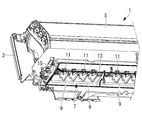
- the interior of the indoor unit 1 is shown in FIG.
- the indoor heat exchanger 5 is attached to the base plate 3 fixed to the wall of the room.
- an air outlet 7 provided in the width direction of the indoor unit 1 is formed below the indoor heat exchanger 5, an air outlet 7 provided in the width direction of the indoor unit 1 is formed.
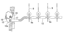
- the blower outlet 7 is provided with a plurality of louvers 9 at predetermined intervals in the width direction (one direction).
- Each louver 9 is a plate made of resin.
- Each louver 9 is rotatably attached to a bearing 11 provided on the main body side of the indoor unit 1.
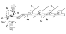
- Each louver 9 is provided with a mounting pin 9a (FIG. 3A), and the mounting pin 9a is rotatably mounted on the connecting member 13.
- connection member 13 is made of resin and is in the shape of a bar extending in the width direction of the indoor unit 1.
- the left end which is one end of the connection member is disposed to be located on the motor bracket 15 side.
- the motor bracket 15 is fixed to the main body of the indoor unit 1 and accommodates a motor for driving the louver 9.
- FIGS. 3A and 3B show enlarged views of the periphery of the connecting member 13 and the motor bracket 15.
- One end of the link member 17 is rotatably attached to the left end of the connection member 13.
- the other end of the link member 17 is attached to the motor shaft 19. Therefore, when the motor shaft 19 is rotated by the motor, the link member 17 is swung, thereby reciprocating the connecting member 13 in the substantially longitudinal direction.
- the reciprocating angle of each louver 9 is changed by the reciprocation of the connecting member 13.
- the rotation angle of the motor shaft 19 is sent to a control unit (not shown).
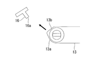
- a stopper 16 is fixed to the motor bracket 15.
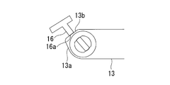
- the stopper 16 restricts the movement of the connecting member 13 by abutting on the tip 13 a of the connecting member 13 as shown in FIGS. 4A and 4B.
- the contact surface 13b of the tip 13a of the connecting member 13 and the contact surface 16a of the stopper 16 are in surface contact. That is, the contact surface 16 a of the stopper 16 is set to face the contact surface 13 b of the connecting member 13.
- the control unit sets a position where the tip 13 a of the connecting member 13 abuts on the stopper 16 as a reference position. Then, based on the reference position, the rotation angle of the motor shaft 19 is controlled, and the position control of each louver 9 is performed.
- the control unit is configured of, for example, a central processing unit (CPU), a random access memory (RAM), a read only memory (ROM), a computer readable storage medium, and the like. Then, a series of processes for realizing various functions are stored in the form of a program, for example, in a storage medium or the like in the form of a program, and the CPU reads this program into a RAM or the like to execute information processing and arithmetic processing. Thus, various functions are realized.
- the program may be installed in advance in a ROM or other storage medium, may be provided as stored in a computer-readable storage medium, or may be distributed via a wired or wireless communication means. Etc. may be applied.
- the computer readable storage medium is a magnetic disk, a magneto-optical disk, a CD-ROM, a DVD-ROM, a semiconductor memory or the like.
- Positioning of the reference position of each louver 9 is performed as follows. First, the motor is driven by the command of the control unit, and the link member 17 is swung by the rotation of the motor shaft 19. The swinging of the link member 17 moves the tip 13a of the connection member 13 to the stopper 16 side, and the contact surface 13b of the connection member 13 is in surface contact with the contact surface 16a of the stopper 16. Thereby, the movement of the connection member 13 is restricted, and the control unit sets this position as a reference position. The control unit rotates the motor shaft 19 based on the reference position to control the wind direction angle of the louver 9.
- the motor bracket 15 for fixing the motor to the main body of the indoor unit 1 is provided with a stopper 16 that abuts on the connecting member 13.
- the connecting member 13 abuts against the stopper 16
- the movement is restricted, and positioning of each louver 9 is performed.
- the stopper 16 is provided on a member different from the motor bracket 15 to which the motor is attached like other members such as a casing. Positioning of each louver 9 can be performed more accurately than in the case.
- each louver 9 is accurately determined by the control unit setting the position where the stopper 16 abuts on the connecting member 13 as the reference position. Thereby, the rotation angle of each louver 9 can be controlled to a desired position.
Landscapes
- Engineering & Computer Science (AREA)
- Chemical & Material Sciences (AREA)
- Combustion & Propulsion (AREA)
- Mechanical Engineering (AREA)
- General Engineering & Computer Science (AREA)
- Air-Flow Control Members (AREA)
- Air Filters, Heat-Exchange Apparatuses, And Housings Of Air-Conditioning Units (AREA)
Priority Applications (2)
| Application Number | Priority Date | Filing Date | Title |
|---|---|---|---|
| EP18798502.3A EP3527905A1 (en) | 2017-05-08 | 2018-04-13 | Indoor unit of air conditioner |
| AU2018266035A AU2018266035B2 (en) | 2017-05-08 | 2018-04-13 | Indoor unit of air conditioner |
Applications Claiming Priority (2)
| Application Number | Priority Date | Filing Date | Title |
|---|---|---|---|
| JP2017-092343 | 2017-05-08 | ||
| JP2017092343A JP6938208B2 (ja) | 2017-05-08 | 2017-05-08 | 空気調和装置の室内機 |
Publications (1)
| Publication Number | Publication Date |
|---|---|
| WO2018207554A1 true WO2018207554A1 (ja) | 2018-11-15 |
Family
ID=64104533
Family Applications (1)
| Application Number | Title | Priority Date | Filing Date |
|---|---|---|---|
| PCT/JP2018/015599 Ceased WO2018207554A1 (ja) | 2017-05-08 | 2018-04-13 | 空気調和装置の室内機 |
Country Status (4)
| Country | Link |
|---|---|
| EP (1) | EP3527905A1 (enExample) |
| JP (1) | JP6938208B2 (enExample) |
| AU (1) | AU2018266035B2 (enExample) |
| WO (1) | WO2018207554A1 (enExample) |
Citations (8)
| Publication number | Priority date | Publication date | Assignee | Title |
|---|---|---|---|---|
| JPH02225931A (ja) * | 1989-02-28 | 1990-09-07 | Daikyo Inc | 空調吹出口装置 |
| JPH06101903A (ja) * | 1992-06-10 | 1994-04-12 | Samsung Electronics Co Ltd | 風向調節装置 |
| JPH10103751A (ja) * | 1996-09-30 | 1998-04-21 | Toshiba Corp | 空気調和装置の室内機 |
| JPH11118186A (ja) | 1997-10-20 | 1999-04-30 | Fujitsu General Ltd | 空気調和機 |
| JP2000168351A (ja) * | 1998-12-07 | 2000-06-20 | Kojima Press Co Ltd | 車両用空気吹出口装置 |
| JP2010121873A (ja) * | 2008-11-20 | 2010-06-03 | Mitsubishi Heavy Ind Ltd | 空気調和機 |
| JP2014129956A (ja) * | 2012-12-28 | 2014-07-10 | Fujitsu General Ltd | 空気調和機および制御回路 |
| JP2016095099A (ja) * | 2014-11-14 | 2016-05-26 | 象印マホービン株式会社 | 送風装置 |
Family Cites Families (4)
| Publication number | Priority date | Publication date | Assignee | Title |
|---|---|---|---|---|
| JPS61265441A (ja) * | 1985-05-20 | 1986-11-25 | Matsushita Electric Ind Co Ltd | 流れ方向制御装置 |
| JP2002243263A (ja) * | 2001-02-20 | 2002-08-28 | Fujitsu General Ltd | 空気調和機 |
| KR100857319B1 (ko) * | 2003-04-30 | 2008-09-05 | 엘지전자 주식회사 | 실외기용 루버 블레이드의 개폐검지장치 및 방법 |
| JP6066783B2 (ja) * | 2013-03-07 | 2017-01-25 | 三菱電機株式会社 | 空気調和機の室内機及びそれを備えた空気調和機 |
-
2017
- 2017-05-08 JP JP2017092343A patent/JP6938208B2/ja active Active
-
2018
- 2018-04-13 EP EP18798502.3A patent/EP3527905A1/en not_active Withdrawn
- 2018-04-13 AU AU2018266035A patent/AU2018266035B2/en active Active
- 2018-04-13 WO PCT/JP2018/015599 patent/WO2018207554A1/ja not_active Ceased
Patent Citations (8)
| Publication number | Priority date | Publication date | Assignee | Title |
|---|---|---|---|---|
| JPH02225931A (ja) * | 1989-02-28 | 1990-09-07 | Daikyo Inc | 空調吹出口装置 |
| JPH06101903A (ja) * | 1992-06-10 | 1994-04-12 | Samsung Electronics Co Ltd | 風向調節装置 |
| JPH10103751A (ja) * | 1996-09-30 | 1998-04-21 | Toshiba Corp | 空気調和装置の室内機 |
| JPH11118186A (ja) | 1997-10-20 | 1999-04-30 | Fujitsu General Ltd | 空気調和機 |
| JP2000168351A (ja) * | 1998-12-07 | 2000-06-20 | Kojima Press Co Ltd | 車両用空気吹出口装置 |
| JP2010121873A (ja) * | 2008-11-20 | 2010-06-03 | Mitsubishi Heavy Ind Ltd | 空気調和機 |
| JP2014129956A (ja) * | 2012-12-28 | 2014-07-10 | Fujitsu General Ltd | 空気調和機および制御回路 |
| JP2016095099A (ja) * | 2014-11-14 | 2016-05-26 | 象印マホービン株式会社 | 送風装置 |
Also Published As
| Publication number | Publication date |
|---|---|
| AU2018266035A1 (en) | 2019-05-23 |
| JP6938208B2 (ja) | 2021-09-22 |
| EP3527905A1 (en) | 2019-08-21 |
| AU2018266035B2 (en) | 2020-06-04 |
| JP2018189310A (ja) | 2018-11-29 |
Similar Documents
| Publication | Publication Date | Title |
|---|---|---|
| US5888133A (en) | Air conditioner | |
| JP5506436B2 (ja) | 除湿機 | |
| KR100809784B1 (ko) | 횡류팬을 포함하는 공기 조화기 | |
| CN103307726B (zh) | 空调导风机构及空调器 | |
| JP2017067354A (ja) | 空気調和装置の室内ユニット | |
| WO2013099353A1 (ja) | 空調室内機 | |
| JP5519232B2 (ja) | 空気調和装置 | |
| US20200224889A1 (en) | Indoor unit of air conditioner | |
| JP2007205584A (ja) | 空気調和機 | |
| WO2018207554A1 (ja) | 空気調和装置の室内機 | |
| KR101410029B1 (ko) | 온도변화에 따라 공급되는 에어의 흐름 형태를 조절하는 디퓨져 | |
| JP2008215721A (ja) | 空気調和機 | |
| CN206347709U (zh) | 室内机以及空调机 | |
| CN108954758A (zh) | 出风机构及具有其的空调器 | |
| JP5506579B2 (ja) | 空気調和機の室内機 | |
| JPH05332604A (ja) | 空気調和機の風向調節装置 | |
| JP2008151477A (ja) | 床置型空気調和機 | |
| JPH0587395A (ja) | 空気調和機 | |
| JP2007240064A (ja) | 風向変更装置 | |
| JP2017040408A (ja) | 空気調和機 | |
| JP2004170056A (ja) | 空気調和機 | |
| JP2002228251A (ja) | 空気調和機室内機の左右風向変更調整装置 | |
| JP2018143915A (ja) | 除湿装置 | |
| JP2008138957A (ja) | 風向変更装置及びこれを備えた空気調節装置 | |
| JP6811876B2 (ja) | 室内機および空気調和機 |
Legal Events
| Date | Code | Title | Description |
|---|---|---|---|
| 121 | Ep: the epo has been informed by wipo that ep was designated in this application |
Ref document number: 18798502 Country of ref document: EP Kind code of ref document: A1 |
|
| ENP | Entry into the national phase |
Ref document number: 2018266035 Country of ref document: AU Date of ref document: 20180413 Kind code of ref document: A |
|
| ENP | Entry into the national phase |
Ref document number: 2018798502 Country of ref document: EP Effective date: 20190515 |
|
| NENP | Non-entry into the national phase |
Ref country code: DE |