WO2018207497A1 - 排ガス浄化触媒装置 - Google Patents
排ガス浄化触媒装置 Download PDFInfo
- Publication number
- WO2018207497A1 WO2018207497A1 PCT/JP2018/013900 JP2018013900W WO2018207497A1 WO 2018207497 A1 WO2018207497 A1 WO 2018207497A1 JP 2018013900 W JP2018013900 W JP 2018013900W WO 2018207497 A1 WO2018207497 A1 WO 2018207497A1
- Authority
- WO
- WIPO (PCT)
- Prior art keywords
- exhaust gas
- catalyst device
- coat layer
- partition wall
- inlet
- Prior art date
Links
- 239000003054 catalyst Substances 0.000 title claims abstract description 120
- 238000000746 purification Methods 0.000 title claims abstract description 87
- 239000011148 porous material Substances 0.000 claims abstract description 150
- 238000005192 partition Methods 0.000 claims abstract description 122
- 238000009826 distribution Methods 0.000 claims abstract description 62
- QSHDDOUJBYECFT-UHFFFAOYSA-N mercury Chemical compound [Hg] QSHDDOUJBYECFT-UHFFFAOYSA-N 0.000 claims abstract description 43
- 229910052753 mercury Inorganic materials 0.000 claims abstract description 43
- 239000010410 layer Substances 0.000 claims description 77
- 239000000758 substrate Substances 0.000 claims description 64
- 239000002002 slurry Substances 0.000 claims description 63
- 238000000034 method Methods 0.000 claims description 43
- 239000011247 coating layer Substances 0.000 claims description 42
- 239000002245 particle Substances 0.000 claims description 42
- 238000011144 upstream manufacturing Methods 0.000 claims description 26
- 238000004519 manufacturing process Methods 0.000 claims description 17
- 238000010304 firing Methods 0.000 claims description 13
- 229910052809 inorganic oxide Inorganic materials 0.000 claims description 13
- 229920000620 organic polymer Polymers 0.000 claims description 4
- 230000003197 catalytic effect Effects 0.000 claims 2
- 239000000463 material Substances 0.000 abstract description 30
- 210000004027 cell Anatomy 0.000 description 86
- 239000013618 particulate matter Substances 0.000 description 30
- 239000011248 coating agent Substances 0.000 description 19
- 238000000576 coating method Methods 0.000 description 19
- PPBRXRYQALVLMV-UHFFFAOYSA-N Styrene Chemical compound C=CC1=CC=CC=C1 PPBRXRYQALVLMV-UHFFFAOYSA-N 0.000 description 16
- 229910000510 noble metal Inorganic materials 0.000 description 15
- 238000011156 evaluation Methods 0.000 description 14
- 230000000052 comparative effect Effects 0.000 description 12
- 239000006255 coating slurry Substances 0.000 description 11
- 239000011230 binding agent Substances 0.000 description 9
- 239000004925 Acrylic resin Substances 0.000 description 8
- 229920000178 Acrylic resin Polymers 0.000 description 8
- 239000000843 powder Substances 0.000 description 8
- 238000002360 preparation method Methods 0.000 description 6
- 239000007787 solid Substances 0.000 description 6
- XLYOFNOQVPJJNP-UHFFFAOYSA-N water Substances O XLYOFNOQVPJJNP-UHFFFAOYSA-N 0.000 description 6
- PNEYBMLMFCGWSK-UHFFFAOYSA-N aluminium oxide Inorganic materials [O-2].[O-2].[O-2].[Al+3].[Al+3] PNEYBMLMFCGWSK-UHFFFAOYSA-N 0.000 description 5
- 238000007581 slurry coating method Methods 0.000 description 5
- 239000004354 Hydroxyethyl cellulose Substances 0.000 description 4
- 229920000663 Hydroxyethyl cellulose Polymers 0.000 description 4
- KDLHZDBZIXYQEI-UHFFFAOYSA-N Palladium Chemical compound [Pd] KDLHZDBZIXYQEI-UHFFFAOYSA-N 0.000 description 4
- MCMNRKCIXSYSNV-UHFFFAOYSA-N Zirconium dioxide Chemical compound O=[Zr]=O MCMNRKCIXSYSNV-UHFFFAOYSA-N 0.000 description 4
- 230000008021 deposition Effects 0.000 description 4
- 235000019447 hydroxyethyl cellulose Nutrition 0.000 description 4
- 239000011812 mixed powder Substances 0.000 description 4
- 230000003647 oxidation Effects 0.000 description 4
- 238000007254 oxidation reaction Methods 0.000 description 4
- BASFCYQUMIYNBI-UHFFFAOYSA-N platinum Chemical compound [Pt] BASFCYQUMIYNBI-UHFFFAOYSA-N 0.000 description 4
- HBMJWWWQQXIZIP-UHFFFAOYSA-N silicon carbide Chemical compound [Si+]#[C-] HBMJWWWQQXIZIP-UHFFFAOYSA-N 0.000 description 4
- 229910010271 silicon carbide Inorganic materials 0.000 description 4
- 229910018879 Pt—Pd Inorganic materials 0.000 description 3
- 239000003153 chemical reaction reagent Substances 0.000 description 3
- HNPSIPDUKPIQMN-UHFFFAOYSA-N dioxosilane;oxo(oxoalumanyloxy)alumane Chemical compound O=[Si]=O.O=[Al]O[Al]=O HNPSIPDUKPIQMN-UHFFFAOYSA-N 0.000 description 3
- 238000010438 heat treatment Methods 0.000 description 3
- 238000005259 measurement Methods 0.000 description 3
- 239000011347 resin Substances 0.000 description 3
- 229920005989 resin Polymers 0.000 description 3
- 238000007789 sealing Methods 0.000 description 3
- 229910002651 NO3 Inorganic materials 0.000 description 2
- NHNBFGGVMKEFGY-UHFFFAOYSA-N Nitrate Chemical compound [O-][N+]([O-])=O NHNBFGGVMKEFGY-UHFFFAOYSA-N 0.000 description 2
- GWEVSGVZZGPLCZ-UHFFFAOYSA-N Titan oxide Chemical compound O=[Ti]=O GWEVSGVZZGPLCZ-UHFFFAOYSA-N 0.000 description 2
- 229910021536 Zeolite Inorganic materials 0.000 description 2
- 238000004458 analytical method Methods 0.000 description 2
- CETPSERCERDGAM-UHFFFAOYSA-N ceric oxide Chemical compound O=[Ce]=O CETPSERCERDGAM-UHFFFAOYSA-N 0.000 description 2
- 229910000422 cerium(IV) oxide Inorganic materials 0.000 description 2
- 239000002131 composite material Substances 0.000 description 2
- ARUVKPQLZAKDPS-UHFFFAOYSA-L copper(II) sulfate Chemical compound [Cu+2].[O-][S+2]([O-])([O-])[O-] ARUVKPQLZAKDPS-UHFFFAOYSA-L 0.000 description 2
- 229910000366 copper(II) sulfate Inorganic materials 0.000 description 2
- 238000007598 dipping method Methods 0.000 description 2
- 239000002612 dispersion medium Substances 0.000 description 2
- 230000000694 effects Effects 0.000 description 2
- 229910044991 metal oxide Inorganic materials 0.000 description 2
- 150000004706 metal oxides Chemical class 0.000 description 2
- 230000001590 oxidative effect Effects 0.000 description 2
- 230000000149 penetrating effect Effects 0.000 description 2
- 238000002459 porosimetry Methods 0.000 description 2
- 239000010457 zeolite Substances 0.000 description 2
- KXGFMDJXCMQABM-UHFFFAOYSA-N 2-methoxy-6-methylphenol Chemical class [CH]OC1=CC=CC([CH])=C1O KXGFMDJXCMQABM-UHFFFAOYSA-N 0.000 description 1
- 229910000505 Al2TiO5 Inorganic materials 0.000 description 1
- 229910052684 Cerium Inorganic materials 0.000 description 1
- RYGMFSIKBFXOCR-UHFFFAOYSA-N Copper Chemical compound [Cu] RYGMFSIKBFXOCR-UHFFFAOYSA-N 0.000 description 1
- OFOBLEOULBTSOW-UHFFFAOYSA-N Propanedioic acid Natural products OC(=O)CC(O)=O OFOBLEOULBTSOW-UHFFFAOYSA-N 0.000 description 1
- 229910052581 Si3N4 Inorganic materials 0.000 description 1
- QCWXUUIWCKQGHC-UHFFFAOYSA-N Zirconium Chemical compound [Zr] QCWXUUIWCKQGHC-UHFFFAOYSA-N 0.000 description 1
- 238000009825 accumulation Methods 0.000 description 1
- 229920000180 alkyd Polymers 0.000 description 1
- 229910052782 aluminium Inorganic materials 0.000 description 1
- XAGFODPZIPBFFR-UHFFFAOYSA-N aluminium Chemical compound [Al] XAGFODPZIPBFFR-UHFFFAOYSA-N 0.000 description 1
- 229910000323 aluminium silicate Inorganic materials 0.000 description 1
- 239000012736 aqueous medium Substances 0.000 description 1
- 239000007864 aqueous solution Substances 0.000 description 1
- 230000015572 biosynthetic process Effects 0.000 description 1
- GWXLDORMOJMVQZ-UHFFFAOYSA-N cerium Chemical compound [Ce] GWXLDORMOJMVQZ-UHFFFAOYSA-N 0.000 description 1
- 238000002485 combustion reaction Methods 0.000 description 1
- 229910052802 copper Inorganic materials 0.000 description 1
- 239000010949 copper Substances 0.000 description 1
- 229910052878 cordierite Inorganic materials 0.000 description 1
- JSKIRARMQDRGJZ-UHFFFAOYSA-N dimagnesium dioxido-bis[(1-oxido-3-oxo-2,4,6,8,9-pentaoxa-1,3-disila-5,7-dialuminabicyclo[3.3.1]nonan-7-yl)oxy]silane Chemical compound [Mg++].[Mg++].[O-][Si]([O-])(O[Al]1O[Al]2O[Si](=O)O[Si]([O-])(O1)O2)O[Al]1O[Al]2O[Si](=O)O[Si]([O-])(O1)O2 JSKIRARMQDRGJZ-UHFFFAOYSA-N 0.000 description 1
- 238000006073 displacement reaction Methods 0.000 description 1
- 238000001035 drying Methods 0.000 description 1
- 239000000839 emulsion Substances 0.000 description 1
- 239000000835 fiber Substances 0.000 description 1
- -1 for example Substances 0.000 description 1
- 239000000446 fuel Substances 0.000 description 1
- 238000010191 image analysis Methods 0.000 description 1
- 238000007654 immersion Methods 0.000 description 1
- 150000002576 ketones Chemical class 0.000 description 1
- 239000007788 liquid Substances 0.000 description 1
- VZCYOOQTPOCHFL-UPHRSURJSA-N maleic acid Chemical compound OC(=O)\C=C/C(O)=O VZCYOOQTPOCHFL-UPHRSURJSA-N 0.000 description 1
- 239000011976 maleic acid Substances 0.000 description 1
- 229910052751 metal Inorganic materials 0.000 description 1
- 239000002184 metal Substances 0.000 description 1
- 239000000203 mixture Substances 0.000 description 1
- 239000003960 organic solvent Substances 0.000 description 1
- 229910052763 palladium Inorganic materials 0.000 description 1
- 230000035515 penetration Effects 0.000 description 1
- 229910052697 platinum Inorganic materials 0.000 description 1
- 229920005749 polyurethane resin Polymers 0.000 description 1
- 239000011164 primary particle Substances 0.000 description 1
- AABBHSMFGKYLKE-SNAWJCMRSA-N propan-2-yl (e)-but-2-enoate Chemical compound C\C=C\C(=O)OC(C)C AABBHSMFGKYLKE-SNAWJCMRSA-N 0.000 description 1
- 229910052761 rare earth metal Inorganic materials 0.000 description 1
- 229910052703 rhodium Inorganic materials 0.000 description 1
- 239000010948 rhodium Substances 0.000 description 1
- MHOVAHRLVXNVSD-UHFFFAOYSA-N rhodium atom Chemical compound [Rh] MHOVAHRLVXNVSD-UHFFFAOYSA-N 0.000 description 1
- 230000000630 rising effect Effects 0.000 description 1
- 238000001878 scanning electron micrograph Methods 0.000 description 1
- 239000011163 secondary particle Substances 0.000 description 1
- RMAQACBXLXPBSY-UHFFFAOYSA-N silicic acid Chemical compound O[Si](O)(O)O RMAQACBXLXPBSY-UHFFFAOYSA-N 0.000 description 1
- HQVNEWCFYHHQES-UHFFFAOYSA-N silicon nitride Chemical compound N12[Si]34N5[Si]62N3[Si]51N64 HQVNEWCFYHHQES-UHFFFAOYSA-N 0.000 description 1
- 239000000243 solution Substances 0.000 description 1
- 239000002344 surface layer Substances 0.000 description 1
- VZCYOOQTPOCHFL-UHFFFAOYSA-N trans-butenedioic acid Natural products OC(=O)C=CC(O)=O VZCYOOQTPOCHFL-UHFFFAOYSA-N 0.000 description 1
- 239000004034 viscosity adjusting agent Substances 0.000 description 1
- 229920003169 water-soluble polymer Polymers 0.000 description 1
- 229910052727 yttrium Inorganic materials 0.000 description 1
- VWQVUPCCIRVNHF-UHFFFAOYSA-N yttrium atom Chemical compound [Y] VWQVUPCCIRVNHF-UHFFFAOYSA-N 0.000 description 1
- 229910052726 zirconium Inorganic materials 0.000 description 1
Images


Classifications
-
- F—MECHANICAL ENGINEERING; LIGHTING; HEATING; WEAPONS; BLASTING
- F01—MACHINES OR ENGINES IN GENERAL; ENGINE PLANTS IN GENERAL; STEAM ENGINES
- F01N—GAS-FLOW SILENCERS OR EXHAUST APPARATUS FOR MACHINES OR ENGINES IN GENERAL; GAS-FLOW SILENCERS OR EXHAUST APPARATUS FOR INTERNAL COMBUSTION ENGINES
- F01N3/00—Exhaust or silencing apparatus having means for purifying, rendering innocuous, or otherwise treating exhaust
- F01N3/02—Exhaust or silencing apparatus having means for purifying, rendering innocuous, or otherwise treating exhaust for cooling, or for removing solid constituents of, exhaust
- F01N3/021—Exhaust or silencing apparatus having means for purifying, rendering innocuous, or otherwise treating exhaust for cooling, or for removing solid constituents of, exhaust by means of filters
- F01N3/022—Exhaust or silencing apparatus having means for purifying, rendering innocuous, or otherwise treating exhaust for cooling, or for removing solid constituents of, exhaust by means of filters characterised by specially adapted filtering structure, e.g. honeycomb, mesh or fibrous
- F01N3/0222—Exhaust or silencing apparatus having means for purifying, rendering innocuous, or otherwise treating exhaust for cooling, or for removing solid constituents of, exhaust by means of filters characterised by specially adapted filtering structure, e.g. honeycomb, mesh or fibrous the structure being monolithic, e.g. honeycombs
-
- B01J35/64—
-
- B—PERFORMING OPERATIONS; TRANSPORTING
- B01—PHYSICAL OR CHEMICAL PROCESSES OR APPARATUS IN GENERAL
- B01D—SEPARATION
- B01D46/00—Filters or filtering processes specially modified for separating dispersed particles from gases or vapours
- B01D46/24—Particle separators, e.g. dust precipitators, using rigid hollow filter bodies
- B01D46/2403—Particle separators, e.g. dust precipitators, using rigid hollow filter bodies characterised by the physical shape or structure of the filtering element
- B01D46/2418—Honeycomb filters
- B01D46/2425—Honeycomb filters characterized by parameters related to the physical properties of the honeycomb structure material
- B01D46/2429—Honeycomb filters characterized by parameters related to the physical properties of the honeycomb structure material of the honeycomb walls or cells
-
- B—PERFORMING OPERATIONS; TRANSPORTING
- B01—PHYSICAL OR CHEMICAL PROCESSES OR APPARATUS IN GENERAL
- B01D—SEPARATION
- B01D46/00—Filters or filtering processes specially modified for separating dispersed particles from gases or vapours
- B01D46/24—Particle separators, e.g. dust precipitators, using rigid hollow filter bodies
- B01D46/2403—Particle separators, e.g. dust precipitators, using rigid hollow filter bodies characterised by the physical shape or structure of the filtering element
- B01D46/2418—Honeycomb filters
- B01D46/2425—Honeycomb filters characterized by parameters related to the physical properties of the honeycomb structure material
- B01D46/24492—Pore diameter
-
- B—PERFORMING OPERATIONS; TRANSPORTING
- B01—PHYSICAL OR CHEMICAL PROCESSES OR APPARATUS IN GENERAL
- B01D—SEPARATION
- B01D46/00—Filters or filtering processes specially modified for separating dispersed particles from gases or vapours
- B01D46/24—Particle separators, e.g. dust precipitators, using rigid hollow filter bodies
- B01D46/2403—Particle separators, e.g. dust precipitators, using rigid hollow filter bodies characterised by the physical shape or structure of the filtering element
- B01D46/2418—Honeycomb filters
- B01D46/2451—Honeycomb filters characterized by the geometrical structure, shape, pattern or configuration or parameters related to the geometry of the structure
- B01D46/2474—Honeycomb filters characterized by the geometrical structure, shape, pattern or configuration or parameters related to the geometry of the structure of the walls along the length of the honeycomb
-
- B—PERFORMING OPERATIONS; TRANSPORTING
- B01—PHYSICAL OR CHEMICAL PROCESSES OR APPARATUS IN GENERAL
- B01D—SEPARATION
- B01D46/00—Filters or filtering processes specially modified for separating dispersed particles from gases or vapours
- B01D46/24—Particle separators, e.g. dust precipitators, using rigid hollow filter bodies
- B01D46/2403—Particle separators, e.g. dust precipitators, using rigid hollow filter bodies characterised by the physical shape or structure of the filtering element
- B01D46/2418—Honeycomb filters
- B01D46/2451—Honeycomb filters characterized by the geometrical structure, shape, pattern or configuration or parameters related to the geometry of the structure
- B01D46/2482—Thickness, height, width, length or diameter
-
- B—PERFORMING OPERATIONS; TRANSPORTING
- B01—PHYSICAL OR CHEMICAL PROCESSES OR APPARATUS IN GENERAL
- B01D—SEPARATION
- B01D53/00—Separation of gases or vapours; Recovering vapours of volatile solvents from gases; Chemical or biological purification of waste gases, e.g. engine exhaust gases, smoke, fumes, flue gases, aerosols
- B01D53/34—Chemical or biological purification of waste gases
- B01D53/73—After-treatment of removed components
-
- B—PERFORMING OPERATIONS; TRANSPORTING
- B01—PHYSICAL OR CHEMICAL PROCESSES OR APPARATUS IN GENERAL
- B01D—SEPARATION
- B01D53/00—Separation of gases or vapours; Recovering vapours of volatile solvents from gases; Chemical or biological purification of waste gases, e.g. engine exhaust gases, smoke, fumes, flue gases, aerosols
- B01D53/34—Chemical or biological purification of waste gases
- B01D53/92—Chemical or biological purification of waste gases of engine exhaust gases
- B01D53/94—Chemical or biological purification of waste gases of engine exhaust gases by catalytic processes
-
- B—PERFORMING OPERATIONS; TRANSPORTING
- B01—PHYSICAL OR CHEMICAL PROCESSES OR APPARATUS IN GENERAL
- B01J—CHEMICAL OR PHYSICAL PROCESSES, e.g. CATALYSIS OR COLLOID CHEMISTRY; THEIR RELEVANT APPARATUS
- B01J23/00—Catalysts comprising metals or metal oxides or hydroxides, not provided for in group B01J21/00
- B01J23/38—Catalysts comprising metals or metal oxides or hydroxides, not provided for in group B01J21/00 of noble metals
- B01J23/40—Catalysts comprising metals or metal oxides or hydroxides, not provided for in group B01J21/00 of noble metals of the platinum group metals
- B01J23/42—Platinum
-
- B—PERFORMING OPERATIONS; TRANSPORTING
- B01—PHYSICAL OR CHEMICAL PROCESSES OR APPARATUS IN GENERAL
- B01J—CHEMICAL OR PHYSICAL PROCESSES, e.g. CATALYSIS OR COLLOID CHEMISTRY; THEIR RELEVANT APPARATUS
- B01J23/00—Catalysts comprising metals or metal oxides or hydroxides, not provided for in group B01J21/00
- B01J23/38—Catalysts comprising metals or metal oxides or hydroxides, not provided for in group B01J21/00 of noble metals
- B01J23/40—Catalysts comprising metals or metal oxides or hydroxides, not provided for in group B01J21/00 of noble metals of the platinum group metals
- B01J23/44—Palladium
-
- B—PERFORMING OPERATIONS; TRANSPORTING
- B01—PHYSICAL OR CHEMICAL PROCESSES OR APPARATUS IN GENERAL
- B01J—CHEMICAL OR PHYSICAL PROCESSES, e.g. CATALYSIS OR COLLOID CHEMISTRY; THEIR RELEVANT APPARATUS
- B01J23/00—Catalysts comprising metals or metal oxides or hydroxides, not provided for in group B01J21/00
- B01J23/70—Catalysts comprising metals or metal oxides or hydroxides, not provided for in group B01J21/00 of the iron group metals or copper
- B01J23/76—Catalysts comprising metals or metal oxides or hydroxides, not provided for in group B01J21/00 of the iron group metals or copper combined with metals, oxides or hydroxides provided for in groups B01J23/02 - B01J23/36
- B01J23/83—Catalysts comprising metals or metal oxides or hydroxides, not provided for in group B01J21/00 of the iron group metals or copper combined with metals, oxides or hydroxides provided for in groups B01J23/02 - B01J23/36 with rare earths or actinides
-
- B—PERFORMING OPERATIONS; TRANSPORTING
- B01—PHYSICAL OR CHEMICAL PROCESSES OR APPARATUS IN GENERAL
- B01J—CHEMICAL OR PHYSICAL PROCESSES, e.g. CATALYSIS OR COLLOID CHEMISTRY; THEIR RELEVANT APPARATUS
- B01J29/00—Catalysts comprising molecular sieves
- B01J29/04—Catalysts comprising molecular sieves having base-exchange properties, e.g. crystalline zeolites
- B01J29/06—Crystalline aluminosilicate zeolites; Isomorphous compounds thereof
- B01J29/70—Crystalline aluminosilicate zeolites; Isomorphous compounds thereof of types characterised by their specific structure not provided for in groups B01J29/08 - B01J29/65
- B01J29/7015—CHA-type, e.g. Chabazite, LZ-218
-
- B—PERFORMING OPERATIONS; TRANSPORTING
- B01—PHYSICAL OR CHEMICAL PROCESSES OR APPARATUS IN GENERAL
- B01J—CHEMICAL OR PHYSICAL PROCESSES, e.g. CATALYSIS OR COLLOID CHEMISTRY; THEIR RELEVANT APPARATUS
- B01J29/00—Catalysts comprising molecular sieves
- B01J29/04—Catalysts comprising molecular sieves having base-exchange properties, e.g. crystalline zeolites
- B01J29/06—Crystalline aluminosilicate zeolites; Isomorphous compounds thereof
- B01J29/70—Crystalline aluminosilicate zeolites; Isomorphous compounds thereof of types characterised by their specific structure not provided for in groups B01J29/08 - B01J29/65
- B01J29/72—Crystalline aluminosilicate zeolites; Isomorphous compounds thereof of types characterised by their specific structure not provided for in groups B01J29/08 - B01J29/65 containing iron group metals, noble metals or copper
- B01J29/723—CHA-type, e.g. Chabazite, LZ-218
-
- B—PERFORMING OPERATIONS; TRANSPORTING
- B01—PHYSICAL OR CHEMICAL PROCESSES OR APPARATUS IN GENERAL
- B01J—CHEMICAL OR PHYSICAL PROCESSES, e.g. CATALYSIS OR COLLOID CHEMISTRY; THEIR RELEVANT APPARATUS
- B01J29/00—Catalysts comprising molecular sieves
- B01J29/04—Catalysts comprising molecular sieves having base-exchange properties, e.g. crystalline zeolites
- B01J29/06—Crystalline aluminosilicate zeolites; Isomorphous compounds thereof
- B01J29/70—Crystalline aluminosilicate zeolites; Isomorphous compounds thereof of types characterised by their specific structure not provided for in groups B01J29/08 - B01J29/65
- B01J29/72—Crystalline aluminosilicate zeolites; Isomorphous compounds thereof of types characterised by their specific structure not provided for in groups B01J29/08 - B01J29/65 containing iron group metals, noble metals or copper
- B01J29/76—Iron group metals or copper
-
- B01J35/30—
-
- B01J35/56—
-
- B01J35/60—
-
- B01J35/657—
-
- B01J35/66—
-
- B—PERFORMING OPERATIONS; TRANSPORTING
- B01—PHYSICAL OR CHEMICAL PROCESSES OR APPARATUS IN GENERAL
- B01J—CHEMICAL OR PHYSICAL PROCESSES, e.g. CATALYSIS OR COLLOID CHEMISTRY; THEIR RELEVANT APPARATUS
- B01J37/00—Processes, in general, for preparing catalysts; Processes, in general, for activation of catalysts
- B01J37/02—Impregnation, coating or precipitation
- B01J37/0215—Coating
- B01J37/0219—Coating the coating containing organic compounds
-
- B—PERFORMING OPERATIONS; TRANSPORTING
- B01—PHYSICAL OR CHEMICAL PROCESSES OR APPARATUS IN GENERAL
- B01J—CHEMICAL OR PHYSICAL PROCESSES, e.g. CATALYSIS OR COLLOID CHEMISTRY; THEIR RELEVANT APPARATUS
- B01J37/00—Processes, in general, for preparing catalysts; Processes, in general, for activation of catalysts
- B01J37/08—Heat treatment
- B01J37/082—Decomposition and pyrolysis
- B01J37/088—Decomposition of a metal salt
-
- F—MECHANICAL ENGINEERING; LIGHTING; HEATING; WEAPONS; BLASTING
- F01—MACHINES OR ENGINES IN GENERAL; ENGINE PLANTS IN GENERAL; STEAM ENGINES
- F01N—GAS-FLOW SILENCERS OR EXHAUST APPARATUS FOR MACHINES OR ENGINES IN GENERAL; GAS-FLOW SILENCERS OR EXHAUST APPARATUS FOR INTERNAL COMBUSTION ENGINES
- F01N3/00—Exhaust or silencing apparatus having means for purifying, rendering innocuous, or otherwise treating exhaust
- F01N3/02—Exhaust or silencing apparatus having means for purifying, rendering innocuous, or otherwise treating exhaust for cooling, or for removing solid constituents of, exhaust
- F01N3/021—Exhaust or silencing apparatus having means for purifying, rendering innocuous, or otherwise treating exhaust for cooling, or for removing solid constituents of, exhaust by means of filters
- F01N3/022—Exhaust or silencing apparatus having means for purifying, rendering innocuous, or otherwise treating exhaust for cooling, or for removing solid constituents of, exhaust by means of filters characterised by specially adapted filtering structure, e.g. honeycomb, mesh or fibrous
-
- F—MECHANICAL ENGINEERING; LIGHTING; HEATING; WEAPONS; BLASTING
- F01—MACHINES OR ENGINES IN GENERAL; ENGINE PLANTS IN GENERAL; STEAM ENGINES
- F01N—GAS-FLOW SILENCERS OR EXHAUST APPARATUS FOR MACHINES OR ENGINES IN GENERAL; GAS-FLOW SILENCERS OR EXHAUST APPARATUS FOR INTERNAL COMBUSTION ENGINES
- F01N3/00—Exhaust or silencing apparatus having means for purifying, rendering innocuous, or otherwise treating exhaust
- F01N3/02—Exhaust or silencing apparatus having means for purifying, rendering innocuous, or otherwise treating exhaust for cooling, or for removing solid constituents of, exhaust
- F01N3/021—Exhaust or silencing apparatus having means for purifying, rendering innocuous, or otherwise treating exhaust for cooling, or for removing solid constituents of, exhaust by means of filters
- F01N3/033—Exhaust or silencing apparatus having means for purifying, rendering innocuous, or otherwise treating exhaust for cooling, or for removing solid constituents of, exhaust by means of filters in combination with other devices
- F01N3/035—Exhaust or silencing apparatus having means for purifying, rendering innocuous, or otherwise treating exhaust for cooling, or for removing solid constituents of, exhaust by means of filters in combination with other devices with catalytic reactors, e.g. catalysed diesel particulate filters
-
- F—MECHANICAL ENGINEERING; LIGHTING; HEATING; WEAPONS; BLASTING
- F01—MACHINES OR ENGINES IN GENERAL; ENGINE PLANTS IN GENERAL; STEAM ENGINES
- F01N—GAS-FLOW SILENCERS OR EXHAUST APPARATUS FOR MACHINES OR ENGINES IN GENERAL; GAS-FLOW SILENCERS OR EXHAUST APPARATUS FOR INTERNAL COMBUSTION ENGINES
- F01N3/00—Exhaust or silencing apparatus having means for purifying, rendering innocuous, or otherwise treating exhaust
- F01N3/08—Exhaust or silencing apparatus having means for purifying, rendering innocuous, or otherwise treating exhaust for rendering innocuous
- F01N3/10—Exhaust or silencing apparatus having means for purifying, rendering innocuous, or otherwise treating exhaust for rendering innocuous by thermal or catalytic conversion of noxious components of exhaust
- F01N3/24—Exhaust or silencing apparatus having means for purifying, rendering innocuous, or otherwise treating exhaust for rendering innocuous by thermal or catalytic conversion of noxious components of exhaust characterised by constructional aspects of converting apparatus
- F01N3/28—Construction of catalytic reactors
Definitions
- the present invention relates to an exhaust gas purification catalyst device.
- PM particulate matter
- the exhaust gas purification filter for example, a plurality of cells partitioned by porous partition walls are opened on the upstream side of the exhaust gas flow and the downstream side is sealed, and the upstream side of the exhaust gas flow is sealed and the downstream side
- a honeycomb structure including an outlet-side cell that is open to the outside.
- Patent Document 1 discloses a heat-resistant base material having a honeycomb structure having a plurality of parallel holes made of porous walls, and adjacent holes are alternately closed at one end, and the base material. And an oxidation catalyst carried on a porous wall constituting the exhaust gas purification structure, wherein the oxidation catalyst is carried on a surface layer that is open in either direction of the wall. Yes.
- Patent Document 2 discloses a filter base material made of a porous material, an inflow side gas flow path whose gas inflow side end is opened, an outflow side gas flow path whose outflow side end is opened, and an inflow side gas.
- a honeycomb structure type filter provided between a flow path and an outflow side gas flow and having a partition wall through which exhaust gas is passed and purified, wherein the average pore diameter of the partition wall is 5 ⁇ m or more and 50 ⁇ m or less, and the inflow side gas flow path
- a honeycomb structure type filter having an average pore diameter of 0.05 ⁇ m or more and 5 ⁇ m or less and a porous film containing a noble metal is described.
- Patent Document 3 discloses a honeycomb structure portion having a porous partition wall that extends from an inflow side end surface to an outflow side end surface to form a plurality of cells serving as exhaust gas flow paths, and an outflow end surface of an inlet cell that is a predetermined cell.
- a plugging portion disposed in the side opening and the inflow end face side opening of the outlet cell which is a remaining cell; a surface collection layer disposed on the surface of the inlet side cell of the partition wall of the honeycomb structure portion; A catalyst for purifying exhaust gas formed on at least one surface selected from the group consisting of the surface of the surface collection layer, the inner surface of the pores formed by the surface collection layer, and the surface of the partition wall on the outlet cell side;
- the exhaust gas purification filter is described in which the amount of catalyst supported from the outflow end face of the honeycomb structure portion to a position of 50 mm is smaller than the amount of catalyst supported on the inflow portion side.
- Patent Document 4 after a noble metal is supported on a support made of a metal oxide containing CeO 2 , reduction treatment is performed at a temperature in the range of 600 to 800 ° C. in a reducing atmosphere, and then in an oxidizing atmosphere, A low-temperature oxidation catalyst is described in which oxidation treatment is performed at a temperature in the range of 600 to 800 ° C. and reduction treatment is further performed at a temperature in the range of 600 to 800 ° C. It is described that the invention according to Patent Document 4 is made with the intention of purifying diesel exhaust gas and the like.
- the conventional exhaust gas purification filters represented by Patent Documents 1 to 4 have a high resistance to the passage of exhaust gas and a high pressure loss, so that fuel consumption tends to deteriorate. Furthermore, if these exhaust gas purification filters are continuously used, the collected PM may accumulate in the filter, and the pressure loss may further increase.
- an object of the present invention is to provide an exhaust gas purification catalyst device in which the pressure loss when used for exhaust gas purification is small and the increase in pressure loss due to PM accumulation is suppressed even when the use is continued for a long time. Is to provide.
- the present invention is as follows.
- An exhaust gas purification catalyst device having a honeycomb substrate and an inlet side coating layer,
- the honeycomb substrate has a plurality of cells partitioned by porous partition walls, and the plurality of cells are formed in an upstream side of the exhaust gas flow, an inlet side cell that is open on the upstream side of the exhaust gas flow and is sealed on the downstream side.
- the inlet side coat layer is present on the surface side of the partition wall of the inlet side cell,
- the proportion of through-pores of 4 ⁇ m or more and 9 ⁇ m or less is 80% by volume or more, and a mercury intrusion method using a mercury porosimeter
- the peak pore diameter measured by is 3.0 ⁇ m or more larger than the peak through-pore diameter measured by the bubble point method using a palm porometer, Exhaust gas purification catalyst device.
- a method for producing an exhaust gas purification catalyst device includes applying a slurry for forming a coat layer in an inlet side cell of the honeycomb substrate to form a slurry coat layer, and firing the honeycomb substrate after forming the slurry coat layer,
- the coating layer forming slurry contains inorganic oxide particles and a pore former, Manufacturing method of exhaust gas purification catalyst device.
- an average particle diameter of the pore former is 10 nm or more and 500 nm or less.
- the method according to any one of [8] to [10], wherein the amount of the slurry coat layer after firing per unit volume of the honeycomb substrate is 1 g / L or more and 15 g / L or less.
- the exhaust gas purification catalyst device of the present invention has a small pressure loss when used for purification of exhaust gas, and suppresses an increase in pressure loss due to PM deposition even when the use is continued for a long time. .
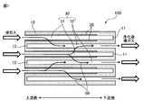
- FIG. 1 is a schematic cross-sectional view for explaining a basic configuration of an exhaust gas purifying catalyst device of the present invention.
- FIG. 2 is a schematic cross-sectional view for explaining the effects of the exhaust gas purifying catalyst device of the present invention in comparison with the prior art.
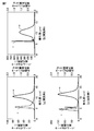
- FIG. 3 is a graph showing the through-pore diameter distribution of the partition walls by the palm porometer and the pore diameter distribution by the mercury porosimeter, measured for the honeycomb substrates used in Examples 1 to 4 and Comparative Examples 1 to 4.
- FIG. 4 is a graph showing the through-pore diameter distribution of the partition wall by the palm porometer and the pore diameter distribution by the mercury porosimeter measured for the exhaust gas purifying catalyst devices obtained in Examples 1 to 4.
- FIG. 1 is a schematic cross-sectional view for explaining a basic configuration of an exhaust gas purifying catalyst device of the present invention.
- FIG. 2 is a schematic cross-sectional view for explaining the effects of the exhaust gas purifying catalyst device of the present invention in comparison with the prior art.
- FIG. 5 is a graph showing the through-pore diameter distribution of the partition wall by the palm porometer and the pore diameter distribution by the mercury porosimeter measured for the exhaust gas purification catalyst devices obtained in Comparative Examples 1 to 4.
- FIG. 6 is a graph showing the through-hole diameter distribution of partition walls by a palm porometer and the pore diameter distribution by a mercury porosimeter, measured for the honeycomb substrates used in Examples 5 to 7 and Comparative Examples 5 and 6.
- FIG. 7 is a graph showing the through-hole pore size distribution of the partition wall by the palm porometer and the pore size distribution by the mercury porosimeter, measured for the exhaust gas purification catalyst devices obtained in Examples 5 to 7.
- FIG. 6 is a graph showing the through-hole diameter distribution of partition walls by a palm porometer and the pore diameter distribution by a mercury porosimeter, measured for the honeycomb substrates used in Examples 5 to 7 and Comparative Examples 5 and 6.
- FIG. 7 is a graph showing the through-hole pore size distribution of the partition wall by the palm
- FIG. 8 is a graph showing the through-pore diameter distribution of the partition walls by the palm porometer and the pore diameter distribution by the mercury porosimeter, measured for the exhaust gas purification catalyst devices obtained in Comparative Examples 5 and 6.
- FIG. 9 is a graph showing the through-pore diameter distribution of the partition wall by the palm porometer and the pore diameter distribution by the mercury porosimeter measured for the exhaust gas purification catalyst device obtained in Example 8.
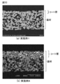
- FIG. 10 is an SEM image (reflection electron image) of the exhaust gas purifying catalyst device obtained in Examples 1 and 4.
- the exhaust gas purification catalyst device of the present invention is An exhaust gas purification catalyst device having a honeycomb substrate and an inlet side coating layer,
- the honeycomb substrate has a plurality of cells partitioned by porous partition walls, and the plurality of cells includes an inlet-side cell that is open on the upstream side of the exhaust gas flow and sealed on the downstream side, and an upstream side of the exhaust gas flow.
- the inlet side coat layer is present on the surface side of the partition wall of the inlet side cell,
- the proportion of through-pores of 4 ⁇ m or more and 9 ⁇ m or less is 80% by volume or more, and a mercury intrusion method using a mercury porosimeter Is larger by 3.0 ⁇ m or more than the peak through-pore diameter measured by the bubble point method using a palm porometer.
- the exhaust gas purification catalyst device (100) of the present invention has a honeycomb substrate (10) and an inlet side coat layer (20).
- the honeycomb substrate (10) has a plurality of cells (30) partitioned by porous partition walls.
- the plurality of cells (30) include an inlet side cell (31) and an outlet side cell (32).
- the inlet side cell (31) opens to the upstream side of the exhaust gas flow, but the downstream side is sealed by the sealing portion (11).
- the outlet side cell (32) is sealed on the upstream side of the exhaust gas flow by the sealing portion (12), but opens to the downstream side.
- the exhaust gas flowing into the inlet side cell (31) of the honeycomb substrate (10) passes through the partition walls of the honeycomb substrate (10) as in the exhaust gas flow (50) indicated by the arrows, It is discharged from the outlet side cell (32).
- the inlet side coat layer (20) exists on the surface side of the partition wall of the inlet side cell (31).
- FIG. 2 shows a schematic cross-sectional view of the exhaust gas purification catalyst device of the present invention in comparison with the prior art exhaust gas purification catalyst device.
- 2 (a) and 2 (b) each show an exhaust gas purification catalyst device of the prior art, and
- FIG. 2 (c) shows an exhaust gas purification catalyst device of the present invention.
- the inlet side coat layer (20) is present in all areas. If particulate matter (PM1) is continuously collected for a long period of time using the exhaust gas purification catalyst device having such a cross-sectional structure, PM1 is clogged in the constricted portion (most detailed) of the pores and the pores are blocked. Incurs great pressure loss.
- the inlet-side coat layer (20) is present only in a shallow portion from the surface of the partition wall of the inlet-side cell (31) toward the partition wall in the depth direction.
- This inlet side coat layer (20) closes the surface of the partition wall of the inlet side cell (31) among the pores of the partition wall, and the pressure loss is originally large.
- the pressure loss is further increased by the deposition of PM1.
- FIG. 2 (c) is a schematic cross-sectional view of a typical structure of the exhaust gas purifying catalyst device of the present invention.
- the inlet side coat layer (20) is present in a relatively shallow part from the surface of the partition wall of the inlet side cell (31) in the depth direction of the partition wall.
- the inlet-side coat layer (20) has fine holes through which gas can flow. Since the exhaust gas purifying catalyst device of the present invention has such a cross-sectional structure, even when PM1 is continuously collected for a long period of time, the pores are blocked by PM1. Moreover, the exhaust gas flowing in from the inlet side cell (31) easily reaches the outlet side cell through the fine pores of the inlet side coat layer (20) and the pores of the partition wall even after PM1 is deposited. can do.
- the present embodiment the preferred embodiment of the exhaust gas purifying catalyst device of the present invention
- the honeycomb base material in the exhaust gas purification catalyst device of the present embodiment has a plurality of cells partitioned by porous partition walls.
- the average pore diameter of the porous partition wall may be, for example, 5 ⁇ m or more, 8 ⁇ m or more, 9 ⁇ m or more, 10 ⁇ m, 11 ⁇ m or more, or 12 ⁇ m or more. If the average pore diameter of the partition walls is 5 ⁇ m or more, it is preferable that the honeycomb base material itself does not cause the pressure loss to increase. On the other hand, the average pore diameter of the partition walls may be, for example, 50 ⁇ m or less, 40 ⁇ m or less, 30 ⁇ m or less, 20 ⁇ m or less, or 15 ⁇ m or less. If the average pore diameter of the partition walls is 50 ⁇ m or less, the honeycomb substrate has a sufficiently high strength, which is preferable.
- the average pore diameter of the partition walls may be evaluated as a peak pore diameter in a pore diameter distribution measured by a mercury intrusion method using a mercury porosimeter.
- the maximum value of the highest peak may be used as the peak pore diameter of the partition.
- the plurality of cells in the honeycomb base material include an inlet side cell that is opened on the upstream side of the exhaust gas flow and sealed on the downstream side, and an outlet side cell that is sealed on the upstream side of the exhaust gas flow and opened on the downstream side.
- the honeycomb substrate is configured such that exhaust gas flows from the upstream end of the inlet side cell, passes through the partition wall, moves to the outlet side cell, and is discharged from the downstream end of the outlet side cell. . Therefore, the entrance side cell and the exit side cell may be adjacent to each other alternately.
- the gas passes through the pores of the partition wall, but PM in the exhaust gas is blocked without passing through the pores of the partition wall, and is trapped in the inlet side cell without moving to the outlet side cell. Is done.
- the PM trapped in the inlet side cell is burned and purified by, for example, a temperature rising process that is performed periodically.
- the cross-sectional shape of the cells in the honeycomb substrate may be any shape such as a circle, an ellipse, a polygon, an indeterminate shape, and a combination thereof.
- the polygon may be a triangle, a quadrangle (particularly a square or a rectangle), a hexagon, an octagon, or the like.
- the cross-sectional area of individual cells in the honeycomb substrate may be, for example, 1 mm 2 or more, 2 mm 2 or more, or 3 mm 2 or more, for example, 7 mm 2 or less, 6 mm 2 or less, or 5 mm 2 or less.
- the porous partition walls in the honeycomb substrate may be made of a heat-resistant porous material, for example.
- the heat resistant porous material may be, for example, silicon carbide, cordierite, aluminum titanate, silicon nitride, metal oxide particles, and the like.
- the shape of the honeycomb base material may be any shape that matches the shape of the exhaust system to which the exhaust gas purification catalyst of the present embodiment is applied, such as a cylindrical shape or a polygonal column shape. A case where the central axis of the honeycomb substrate is curved or bent in the middle is also acceptable.
- the size of the honeycomb substrate may be appropriately set according to the size of the exhaust system to which the honeycomb substrate is applied.
- the cross-sectional area of the honeycomb base material 8,000 mm 2 or more, 10,000 mm 2 or more, 15,000 mm 2 or more, or 20,000mm may be two or more, 130,000Mm 2 below, 120,000Mm 2 or less, 100 , 000 mm 2 or less, 80,000 2 or less, 50,000 mm 2 or less, or 30,000mm may be two or less.
- the length of the honeycomb substrate may be 50 mm or more, 75 mm or more, or 100 mm or more, and may be 400 mm or less, 350 mm or less, or 300 mm or less.
- the inlet side coat layer in the exhaust gas purifying catalyst device of the present embodiment exists on the surface side of the partition wall of the inlet side cell.
- the inlet side coat layer may be present only within a range from the surface of the partition wall of the inlet side cell to the depth of 30% of the partition wall thickness in the depth direction of the partition wall.
- the existence range of the inlet side coating layer is from the surface of the partition wall of the inlet side cell to the depth of the partition wall up to 25% depth, 20% depth, 15% depth, or 10%. It may be only within the range up to the depth. Since the inlet side coat layer exists only in a shallow range from the partition wall surface of the inlet side cell toward the depth of the partition wall to a depth of 30% of the partition wall thickness, PM collection is continued for a long period of time. Even if it is performed, an increase in pressure loss is suppressed, which is preferable.
- the existence range of the inlet side coat layer is 3% or more, 4% or more, 5% or more, 6% or more, 7% or more of the partition wall thickness from the partition wall surface of the inlet side cell toward the partition wall depth direction. Or it may be 8% or more.
- PM can be collected with high efficiency, And it is preferable at the point which exhaust gas can be highly purified.
- the inlet side coat layer is preferably present at a significant length from the upstream end of the exhaust gas flow of the honeycomb base material from the viewpoint of effective PM collection and exhaust gas purification.
- the existence range of the inlet side coating layer from the upstream end of the exhaust gas flow exists over a length of 70% or more, 75% or more, 80% or more, or 85% or more with respect to the honeycomb substrate length. It may be.
- the existence range of the inlet-side coat layer from the upstream end of the exhaust gas flow is 98% or less, 96 with respect to the honeycomb substrate length. % Or less, 94% or less, 92% or less, or 90% or less.
- the inlet side coating layer may contain inorganic oxide particles, and may optionally further contain a noble metal, an inorganic binder, and the like.
- the entrance-side coat layer contains a noble metal
- the noble metal may be supported on a part or all of the inorganic oxide particles.
- the inorganic oxide particles in the entrance-side coat layer may be particles made of an oxide containing one or more metal atoms selected from the group consisting of aluminum, zirconium, cerium, yttrium, rare earth elements, and the like.
- the noble metal may be at least one selected from palladium, platinum, rhodium, and the like.
- the inorganic binder may be, for example, alumina sol, titania sol or the like.
- the inlet side coat layer has fine holes.
- the micropores in the inlet side coating layer are pores derived from the pore former contained in a slurry for forming a coating layer described later.
- the fine pore diameter distribution of the inlet side coat layer can be estimated from the through pore diameter distribution measured by the bubble point method using a palm porometer for the exhaust gas purification catalyst device in the present embodiment. This will be described later.
- the exhaust gas purifying catalyst device of the present embodiment may have an outlet side coat layer in addition to the inlet side coat layer on the honeycomb substrate.
- the exit side coat layer may be present on the surface of the partition wall of the exit side cell or in the partition wall.
- the outlet side coating layer is formed from the surface of the partition wall of the outlet side cell in the depth direction of the partition wall up to a depth of 100%, a depth of 50%, a depth of 40%, a depth of 30%, 20 It may be present only within a range of up to 10% depth or up to 10% depth.
- the outlet side coat layer exists from the downstream end of the exhaust gas flow of the honeycomb base material over a length of 50% or less, 45% or less, 40% or less, 35% or less, or 30% or less of the honeycomb base material length. You can do it.
- the outlet side coat layer may contain inorganic oxide particles, and may optionally further contain a noble metal, an inorganic binder, and the like.
- the exit side coat layer contains a noble metal
- the noble metal may be supported on a part or all of the inorganic oxide particles.
- the outlet side coating layer does not need to have fine holes, but may have them.
- the components and configuration of the outlet side coat layer may be the same as or different from those of the inlet side coat layer.
- the exhaust gas purification catalyst device of the present embodiment is In the through-pore diameter distribution of the partition walls measured by the bubble point method using a palm porometer, the proportion of through-pores of 4 ⁇ m or more and 9 ⁇ m or less is 80% by volume or more, and a mercury intrusion method using a mercury porosimeter Is larger by 3.0 ⁇ m or more than the peak through-pore diameter measured by the bubble point method using a palm porometer.
- the partition pore diameter distribution measured by the bubble point method using a palm porometer is the narrowest part when the pores penetrating the partition wall are observed from the partition wall surface of the inlet side cell to the partition wall surface of the outlet side cell. This is a pore size distribution reflecting the diameter of each.
- the pore size distribution measured by mercury porosimetry using one mercury porosimeter is as follows. For all pores (including non-penetrating pores) other than closed pores, from the partition wall surface of the inlet cell to the outlet cell. The distribution reflects the diameter of the entire region up to the partition wall surface.
- the ratio of the through-pores of 4 ⁇ m or more and 9 ⁇ m or less is 80% by volume or more. It means that the ratio of the through holes that are 4 ⁇ m or more and 9 ⁇ m or less is 80% by volume or more with respect to all the through holes.
- This ratio is a pore diameter of 4 ⁇ m or more and 9 ⁇ m or less in a graph in which the horizontal axis represents the through-pore diameter measured by the bubble point method using a palm porometer and the vertical axis represents the dimensionless number of pore frequencies. It may be evaluated as the area ratio of the region.
- the pore frequency is an amount corresponding to the gas flow rate when measuring the through-pore diameter distribution.
- the peak pore diameter measured by mercury porosimetry using a mercury porosimeter is 3.0 ⁇ m or more larger than the peak through pore diameter measured by bubble point method using a palm porometer. It means that the difference between the average pore diameter and the average value of the diameter of the thinnest through hole is large. In other words, it means that the average pore diameter of all the pores of the partition wall is sufficiently large and the diameter of the thinnest part of the through hole is sufficiently small. If the average pore diameter of all the pores is sufficiently large, the flow of exhaust gas is not hindered, so that the pressure loss can be reduced. When the diameter of the thinnest part of the through hole is sufficiently small, PM can be collected effectively.
- the through-pore diameter distribution of the partition wall which is measured by a bubble point method using a palm porometer, is presumed to reflect the pore diameter distribution of the micropores possessed by the inlet-side coat layer.
- the region with the narrowest diameter of the through hole of the partition wall exists in the range from the partition wall surface of the inlet side cell to the depth direction of the partition wall, preferably to a depth of 30% of the partition wall thickness.
- the narrowest diameter portion of the through hole of the partition wall is 25% deep, 20% deep, 15% deep from the partition wall surface of the inlet side cell toward the partition wall depth direction, or 15% deep, or It may be present in the range up to 10% depth.
- the ratio of the through-pores of 4 ⁇ m or more and 9 ⁇ m or less in the through-pore diameter distribution of the partition walls is 80% by volume or more, 85% by volume or more, 90% by volume or more, or 95% by volume or more, and 100% by volume. It may be.
- the exhaust gas purifying catalyst device having such a through-hole diameter distribution can suppress an increase in pressure loss even if PM is continuously collected for a long period of time.
- the difference between the peak pore diameter measured by the mercury intrusion method using a mercury porosimeter and the peak through pore diameter measured by the bubble point method using a palm porometer is 3 0.0 ⁇ m or more, 3.5 ⁇ m or more, 4.0 ⁇ m or more, 4.5 ⁇ m or more, or 5.0 ⁇ m or more.
- This value may be 10.0 ⁇ m or less, 9.0 ⁇ m or less, 8.0 ⁇ m or less, or 7.0 ⁇ m.
- the peak pore diameter measured by the mercury intrusion method using a mercury porosimeter is 9 ⁇ m or more, 10 ⁇ m or more, 11 ⁇ m or more, or 12 ⁇ m or more from the viewpoint of ensuring good exhaust gas circulation. It may be. On the other hand, this value may be 50 ⁇ m or less, 40 ⁇ m or less, 30 ⁇ m or less, 20 ⁇ m or less, or 15 ⁇ m or less from the viewpoint of obtaining an effective filter effect.
- the exhaust gas purifying catalyst device of the present invention as described above may be manufactured, for example, by the following method.
- the coating layer forming slurry contains inorganic oxide particles and a pore former, Manufacturing method of exhaust gas purification catalyst device.
- this embodiment of the method for manufacturing an exhaust gas purification catalyst device of the present invention will be described as an example.
- honeycomb substrate used in the method for manufacturing the exhaust gas purification catalyst device of the present embodiment may be appropriately selected from those described above as the honeycomb substrate in the exhaust gas purification catalyst device of the present embodiment. .
- the slurry for forming a coat layer used in the method for manufacturing an exhaust gas purification catalyst device of the present embodiment includes inorganic oxide particles and a pore former.
- the slurry for forming a coat layer may optionally further contain a noble metal catalyst, an inorganic binder, a viscosity modifier and the like.
- the noble metal catalyst may be supported on a part or all of the inorganic oxide particles.
- the inorganic oxide particles, the noble metal catalyst, and the inorganic binder in the slurry for forming the coat layer may be the same as the inorganic oxide, the noble metal catalyst, and the inorganic binder, respectively, included in the inlet side coat layer.
- the particle diameter of the inorganic oxide particles supporting or not supporting the noble metal catalyst is, for example, 0.1 ⁇ m or more, 0.3 ⁇ m or more, 0.5 ⁇ m or more, 0 as the median diameter.
- the pore former in the slurry for forming the coating layer has a function of burning out in the baking step after coating and forming fine pores in the inlet side coating layer. Therefore, it may be a particle made of a material that is stably present as primary particles or secondary particles in the slurry for forming a coating layer and the slurry coating layer, and easily disappears by firing.
- the pore former contained in the coating layer forming slurry may be, for example, organic polymer particles.
- Organic polymer particles include, for example, (meth) acrylic resin particles, styrene / (meth) acrylic resin particles, polyurethane resin particles, maleic acid resin particles, styrene / maleic resin particles, alkyd resin particles, rosin-modified phenolic resin particles Or ketone resin particles.
- the average particle diameter of the pore former may be, for example, 500 nm or less, 400 nm or less, 300 nm or less, 200 nm or less, or 100 nm or less as the median diameter from the viewpoint of ensuring effective collection of PM.
- the median diameter of the pore former may be 10 nm or more, 20 nm or more, 40 nm or more, 60 nm or more, 80 nm or more, or 100 nm or more from the viewpoint of ensuring good exhaust gas circulation even after PM collection.
- the pore former may be used for preparing a slurry for forming a coat layer as an emulsion.
- the content of the pore former in the slurry for forming the coating layer is 100% by mass based on the total solid content of the slurry from the viewpoint of ensuring the PM collection and ensuring the mechanical strength of the inlet side coating layer. In some cases, for example, it may be 50% by mass or less, 45% by mass or less, 40% by mass or less, 35% by mass or less, or 30% by mass or less.
- the pore former in the case where the total solid content of the slurry for forming the coating layer is 100% by mass from the viewpoint that effective fine pores should be formed to ensure good exhaust gas circulation even after PM collection. May be 5 mass% or more, 10 mass% or more, 12 mass% or more, 15 mass% or more, 18 mass% or more, or 20 mass% or more, for example.
- the dispersion medium of the slurry for forming the coat layer may be an aqueous medium, for example, water or a mixture of water and a water-soluble organic solvent.
- the dispersion medium of the slurry for forming the coating layer may typically be water.
- the existence range of the inlet side coating layer from the partition wall surface of the inlet side cell in the depth direction of the partition wall is adjusted.
- the solid content concentration and the viscosity of the slurry for forming the coating layer may be appropriately set by those skilled in the art according to the desired existence range of the inlet side coating layer. Adjustment of the viscosity of the slurry for forming the coat layer may be performed, for example, by adding a water-soluble polymer such as hydroxyethyl cellulose to the slurry.
- the slurry for forming the coating layer is applied in the inlet side cell of the honeycomb substrate to form a slurry coating layer.
- coating may be performed over desired length from the upstream edge part of an exhaust gas flow of an inlet side coating layer.
- the application range is, for example, 70% or more, 75% or more, 80% or more, or 85% or more of the length of the honeycomb base material from the upstream end of the exhaust gas flow of the inlet side coating layer. For example, it may be performed over a length of 98% or less, 96% or less, 94% or less, 92% or less, or 90% or less.
- the application method may be, for example, a push-up method, a suction method, an immersion method, or the like.
- the coating layer forming slurry is pushed up from the lower opening end of the honeycomb substrate held so that the cell is in the vertical direction with the opening end of the inlet side cell on the lower side.
- coating is performed by placing a slurry for forming a coating layer at the opening end of the inlet side cell of the honeycomb substrate held so that the cells are vertically oriented, and sucking from the opposite end of the outlet side cell.
- coating is performed by dipping the honeycomb base material into the slurry for forming the coating layer from the opening end side of the inlet side cell.
- the amount of the slurry coat layer formed by coating is 1 g / L or more, 3 g / L or more, 5 g / L or more, or 7 g / L or more as the amount of the slurry coating layer after firing per unit volume of the honeycomb substrate. It may be 15 g / L or less, 12 g / L or less, 10 g / L or less, or 8 g / L or less.
- a slurry for forming a coat layer may be applied to the outlet side cell of the honeycomb substrate to form a slurry coat layer.
- the coating layer forming slurry applied to the outlet side cell may be the same as or different from the slurry applied to the inlet side cell.
- the exhaust gas purification catalyst of the present embodiment can be obtained by firing the honeycomb substrate after forming the slurry coat layer.
- the firing step may be performed by heating the honeycomb substrate after forming the slurry coat layer under an appropriate environment such as an inert atmosphere or an oxidizing atmosphere.
- the heating temperature in the firing step may be, for example, 400 ° C. or higher, 500 ° C. or higher, or 600 ° C. or higher, for example, 800 ° C. or lower, 700 ° C. or lower, or 600 ° C. or lower.
- the heating time may be, for example, 5 minutes or more, 30 minutes or more, or 1 hour or more, for example, 20 hours or less, 10 hours or less, 8 hours or less, or 6 hours or less.
- Example 1 Preparation of slurry for coating After impregnating alumina powder in an aqueous solution containing Pt nitrate and Pd nitrate, drying and firing were performed, and 3% by mass of Pt and 1% by mass as mass ratios relative to the mass of alumina. Pt—Pd / Al powder carrying Pd was obtained. 100 g of this Pt—Pd / Al powder was mixed with 50 g of ceria / zirconia composite oxide powder, and then milled to adjust the average particle size to 1 ⁇ m to obtain a mixed powder. To 150 g of this mixed powder, 10 g of alumina sol binder and 300 g of pure water were added and mixed to form a slurry.
- a styrene / acrylic resin particle as a pore-forming material was added to the slurry, and hydroxyethylcellulose was further added to adjust the viscosity to obtain a coating slurry.
- the average particle size of the styrene / acrylic resin particles used here was 100 nm, and the proportion of the styrene / acrylic resin particles used was 30% by mass with respect to the total solid content in the obtained coating slurry. .
- FIG. 3 shows the through-pore diameter distribution of the partition walls by the palm porometer and the pore diameter distribution by the mercury porosimeter, which were measured using this base material as a measurement target.
- This exhaust gas purification catalyst device is presumed to have a cross-sectional structure as shown in FIG.
- FIG. 4 (a) The through-pore diameter distribution of the partition walls of the honeycomb base material measured here is shown in FIG. 4 (a).
- the exhaust gas purification catalyst device produced above was mounted on an exhaust system of a diesel engine with a displacement of 3,000 cc, and was operated for 2 hours under the conditions of 2,000 rpm and 60 Nm. Thereafter, the catalyst device was recovered, pressure loss was measured in the same manner as described above, and the obtained result was used as a pressure loss value after PM deposition.
- Examples 2 to 4 and Comparative Examples 2 and 3 A slurry for coating was prepared in the same manner as in Example 1, except that the amount of pore former used was as shown in Table 1, and the viscosity was appropriately changed by changing the amount of hydroxyethyl cellulose added. Using this slurry, an exhaust gas purification catalyst device was prepared and evaluated in the same manner as in Example 1 except that the coating length from the upstream side of the exhaust gas flow was as shown in Table 1. The results are summarized in Table 2 and Table 3. In addition, the through pore diameter distribution of the partition wall by the palm porometer and the pore diameter distribution by the mercury porosimeter measured at the time of evaluation are shown in FIGS. 4 (b) to 4 (d) and FIGS. 5 (b) and 5 (c). Indicated.
- the exhaust gas purification catalyst devices obtained in Examples 2 to 4 are presumed to have a cross-sectional structure as shown in FIG. 2 (c), and the exhaust gas purification catalyst devices obtained in Comparative Examples 2 and 3 are used. Is considered to have a cross-sectional structure as shown in FIG.
- Example 5 As a base material, a cylindrical SiC honeycomb structure having a diameter of 160 mm and a length of 135 mm (diesel particulate collection filter, average pore diameter of 10.5 ⁇ m (notified value), porosity of 41 vol% (notified value)) was used. Other than that, an exhaust gas purifying catalyst device was produced and evaluated in the same manner as in Example 1. The results are summarized in Table 2 and Table 3.
- the through-pore diameter distribution of the partition walls measured by the palm porometer and the pore diameter distribution measured by the mercury porosimeter measured for the base material used here are shown in FIG. Moreover, the through-pore diameter distribution of the partition wall by the palm porometer and the pore diameter distribution by the mercury porosimeter measured for the obtained exhaust gas purification catalyst device are shown in FIG.
- Examples 6 and 7 A slurry for coating was prepared in the same manner as in Example 1 except that the average particle diameter and the amount of the pore former were as shown in Table 1.
- An exhaust gas purification catalyst device was produced and evaluated in the same manner as in Example 5 except that this slurry was used. The results are summarized in Table 2 and Table 3. Moreover, the through-pore diameter distribution of the partition wall by the palm porometer and the pore diameter distribution by the mercury porosimeter measured at the time of evaluation are shown in FIGS. 7B and 7C.
- ⁇ Comparative Example 6> Preparation of slurry for coating 90 g of aluminosilicate fibers having an average diameter of 3 ⁇ m and an average length of 105 ⁇ m, 10 g of silica sol binder, and 450 g of pure water are mixed, and further, hydroxyethylcellulose is added to adjust the viscosity. An industrial slurry was obtained.
- a styrene / acrylic resin particle as a pore former was added to the slurry, and the viscosity was adjusted to obtain a coating slurry.
- the average particle diameter of the styrene / acrylic resin particles used here was 100 nm, and the use ratio of the styrene / acrylic resin particles was 10% by mass with respect to the total solid content in the obtained coating slurry. .
Priority Applications (4)
| Application Number | Priority Date | Filing Date | Title |
|---|---|---|---|
| AU2018265936A AU2018265936B2 (en) | 2017-05-11 | 2018-03-30 | Exhaust gas purification catalyst device |
| EP18799107.0A EP3623048A4 (en) | 2017-05-11 | 2018-03-30 | EXHAUST GAS PURIFICATION CATALYST DEVICE |
| CN201880028248.5A CN110573250B (zh) | 2017-05-11 | 2018-03-30 | 排气净化催化剂装置 |
| US16/606,362 US11149604B2 (en) | 2017-05-11 | 2018-03-30 | Exhaust gas purification catalyst device |
Applications Claiming Priority (2)
| Application Number | Priority Date | Filing Date | Title |
|---|---|---|---|
| JP2017094559A JP6407349B1 (ja) | 2017-05-11 | 2017-05-11 | 排ガス浄化触媒装置 |
| JP2017-094559 | 2017-05-11 |
Publications (1)
| Publication Number | Publication Date |
|---|---|
| WO2018207497A1 true WO2018207497A1 (ja) | 2018-11-15 |
Family
ID=63855163
Family Applications (1)
| Application Number | Title | Priority Date | Filing Date |
|---|---|---|---|
| PCT/JP2018/013900 WO2018207497A1 (ja) | 2017-05-11 | 2018-03-30 | 排ガス浄化触媒装置 |
Country Status (6)
| Country | Link |
|---|---|
| US (1) | US11149604B2 (zh) |
| EP (1) | EP3623048A4 (zh) |
| JP (1) | JP6407349B1 (zh) |
| CN (1) | CN110573250B (zh) |
| AU (1) | AU2018265936B2 (zh) |
| WO (1) | WO2018207497A1 (zh) |
Cited By (1)
| Publication number | Priority date | Publication date | Assignee | Title |
|---|---|---|---|---|
| WO2020141188A1 (de) * | 2019-01-04 | 2020-07-09 | Umicore Ag & Co. Kg | Verfahren zur herstellung von katalytisch aktiven wandflussfiltern |
Families Citing this family (8)
| Publication number | Priority date | Publication date | Assignee | Title |
|---|---|---|---|---|
| WO2020031975A1 (ja) * | 2018-08-09 | 2020-02-13 | エヌ・イーケムキャット株式会社 | 触媒塗工ガソリンパティキュレートフィルター及びその製造方法 |
| JP6956139B2 (ja) * | 2019-04-26 | 2021-10-27 | 株式会社Soken | 排ガス浄化フィルタ |
| JP6947200B2 (ja) * | 2019-05-15 | 2021-10-13 | 株式会社デンソー | 排ガス浄化フィルタ |
| KR20220110763A (ko) | 2019-12-19 | 2022-08-09 | 바스프 코포레이션 | 미립자 물질을 포획하기 위한 촉매 물품 |
| JP7475138B2 (ja) | 2019-12-27 | 2024-04-26 | 株式会社キャタラー | 排ガス浄化用触媒 |
| JP7332530B2 (ja) * | 2020-04-21 | 2023-08-23 | トヨタ自動車株式会社 | 排ガス浄化装置 |
| CN117999126A (zh) | 2021-10-14 | 2024-05-07 | 三井金属矿业株式会社 | 废气净化催化剂及其制造方法 |
| WO2023096765A1 (en) * | 2021-11-24 | 2023-06-01 | Corning Incorporated | Emissions treatment articles with inorganic filtration deposits and catalytic material |
Citations (10)
| Publication number | Priority date | Publication date | Assignee | Title |
|---|---|---|---|---|
| JP2006007117A (ja) | 2004-06-25 | 2006-01-12 | Ne Chemcat Corp | 排気ガス浄化構造体および該構造体を用いた排気ガス浄化方法 |
| JP2006095352A (ja) * | 2004-09-28 | 2006-04-13 | Ngk Insulators Ltd | ハニカムフィルタ及びその製造方法 |
| WO2008047558A1 (en) * | 2006-09-28 | 2008-04-24 | Hitachi Metals, Ltd. | Ceramic honeycomb structure and process for producing ceramic honeycomb structure |
| JP2009119430A (ja) | 2007-11-19 | 2009-06-04 | Toyota Central R&D Labs Inc | 低温酸化触媒、その製造方法、および低温酸化触媒を用いた排ガスの浄化方法 |
| JP2010269270A (ja) | 2009-05-22 | 2010-12-02 | Sumitomo Osaka Cement Co Ltd | ハニカム構造型フィルタ |
| WO2011125797A1 (ja) * | 2010-04-01 | 2011-10-13 | 日立金属株式会社 | セラミックハニカムフィルタ及びその製造方法 |
| JP2012200642A (ja) * | 2011-03-24 | 2012-10-22 | Ngk Insulators Ltd | ハニカムフィルタ及びその製造方法 |
| JP2012200670A (ja) * | 2011-03-25 | 2012-10-22 | Ngk Insulators Ltd | ハニカムフィルタ及びその製造方法 |
| JP2014184356A (ja) * | 2013-03-21 | 2014-10-02 | Ngk Insulators Ltd | ハニカム触媒担体 |
| JP2014188466A (ja) | 2013-03-27 | 2014-10-06 | Ngk Insulators Ltd | 排ガス浄化フィルタ及び排ガス浄化フィルタの製造方法 |
Family Cites Families (19)
| Publication number | Priority date | Publication date | Assignee | Title |
|---|---|---|---|---|
| JPS63185425A (ja) * | 1987-01-28 | 1988-08-01 | Ngk Insulators Ltd | 排ガス浄化用セラミツクハニカムフイルタ |
| GB9919013D0 (en) * | 1999-08-13 | 1999-10-13 | Johnson Matthey Plc | Reactor |
| JP3872384B2 (ja) * | 2002-06-13 | 2007-01-24 | トヨタ自動車株式会社 | 排ガス浄化フィルタ触媒 |
| JP3874270B2 (ja) * | 2002-09-13 | 2007-01-31 | トヨタ自動車株式会社 | 排ガス浄化フィルタ触媒及びその製造方法 |
| US7119044B2 (en) * | 2003-06-11 | 2006-10-10 | Delphi Technologies, Inc. | Multiple washcoats on filter substrate |
| DE10335785A1 (de) * | 2003-08-05 | 2005-03-10 | Umicore Ag & Co Kg | Katalysatoranordnung und Verfahren zur Reinigung des Abgases von mager betriebenen Verbrennungsmotoren |
| US7722829B2 (en) * | 2004-09-14 | 2010-05-25 | Basf Catalysts Llc | Pressure-balanced, catalyzed soot filter |
| WO2008011146A1 (en) * | 2006-07-21 | 2008-01-24 | Dow Global Technologies Inc. | Improved zone catalyzed soot filter |
| JP5616059B2 (ja) * | 2007-04-27 | 2014-10-29 | 日本碍子株式会社 | ハニカムフィルタ |
| GB0812544D0 (en) * | 2008-07-09 | 2008-08-13 | Johnson Matthey Plc | Exhaust system for a lean burn IC engine |
| KR101028548B1 (ko) * | 2008-09-05 | 2011-04-11 | 기아자동차주식회사 | 배기가스 정화장치 |
| JP2010167366A (ja) | 2009-01-22 | 2010-08-05 | Ngk Insulators Ltd | ハニカム触媒体 |
| US20110244359A1 (en) | 2009-10-16 | 2011-10-06 | Hideyuki Ueda | Membrane electrode assembly for fuel cell and fuel cell using the same |
| WO2011125768A1 (ja) * | 2010-03-31 | 2011-10-13 | 日本碍子株式会社 | ハニカムフィルタ |
| US8591820B2 (en) * | 2011-03-11 | 2013-11-26 | Corning Incorporated | Honeycomb filters for reducing NOx and particulate matter in diesel engine exhaust |
| JP5599747B2 (ja) | 2011-03-24 | 2014-10-01 | 日本碍子株式会社 | ハニカム構造体及びその製造方法 |
| KR101588785B1 (ko) * | 2011-03-31 | 2016-01-27 | 현대자동차 주식회사 | 밀봉된 하니컴 구조체 |
| JP5859752B2 (ja) | 2011-06-17 | 2016-02-16 | 日本碍子株式会社 | 排ガス浄化フィルタ |
| JP6231909B2 (ja) | 2014-03-14 | 2017-11-15 | 日本碍子株式会社 | 目封止ハニカム構造体及びその製造方法 |
-
2017
- 2017-05-11 JP JP2017094559A patent/JP6407349B1/ja active Active
-
2018
- 2018-03-30 EP EP18799107.0A patent/EP3623048A4/en active Pending
- 2018-03-30 US US16/606,362 patent/US11149604B2/en active Active
- 2018-03-30 WO PCT/JP2018/013900 patent/WO2018207497A1/ja unknown
- 2018-03-30 AU AU2018265936A patent/AU2018265936B2/en active Active
- 2018-03-30 CN CN201880028248.5A patent/CN110573250B/zh active Active
Patent Citations (10)
| Publication number | Priority date | Publication date | Assignee | Title |
|---|---|---|---|---|
| JP2006007117A (ja) | 2004-06-25 | 2006-01-12 | Ne Chemcat Corp | 排気ガス浄化構造体および該構造体を用いた排気ガス浄化方法 |
| JP2006095352A (ja) * | 2004-09-28 | 2006-04-13 | Ngk Insulators Ltd | ハニカムフィルタ及びその製造方法 |
| WO2008047558A1 (en) * | 2006-09-28 | 2008-04-24 | Hitachi Metals, Ltd. | Ceramic honeycomb structure and process for producing ceramic honeycomb structure |
| JP2009119430A (ja) | 2007-11-19 | 2009-06-04 | Toyota Central R&D Labs Inc | 低温酸化触媒、その製造方法、および低温酸化触媒を用いた排ガスの浄化方法 |
| JP2010269270A (ja) | 2009-05-22 | 2010-12-02 | Sumitomo Osaka Cement Co Ltd | ハニカム構造型フィルタ |
| WO2011125797A1 (ja) * | 2010-04-01 | 2011-10-13 | 日立金属株式会社 | セラミックハニカムフィルタ及びその製造方法 |
| JP2012200642A (ja) * | 2011-03-24 | 2012-10-22 | Ngk Insulators Ltd | ハニカムフィルタ及びその製造方法 |
| JP2012200670A (ja) * | 2011-03-25 | 2012-10-22 | Ngk Insulators Ltd | ハニカムフィルタ及びその製造方法 |
| JP2014184356A (ja) * | 2013-03-21 | 2014-10-02 | Ngk Insulators Ltd | ハニカム触媒担体 |
| JP2014188466A (ja) | 2013-03-27 | 2014-10-06 | Ngk Insulators Ltd | 排ガス浄化フィルタ及び排ガス浄化フィルタの製造方法 |
Non-Patent Citations (1)
| Title |
|---|
| See also references of EP3623048A4 |
Cited By (1)
| Publication number | Priority date | Publication date | Assignee | Title |
|---|---|---|---|---|
| WO2020141188A1 (de) * | 2019-01-04 | 2020-07-09 | Umicore Ag & Co. Kg | Verfahren zur herstellung von katalytisch aktiven wandflussfiltern |
Also Published As
| Publication number | Publication date |
|---|---|
| CN110573250B (zh) | 2022-06-10 |
| US11149604B2 (en) | 2021-10-19 |
| US20210189930A1 (en) | 2021-06-24 |
| AU2018265936B2 (en) | 2020-04-16 |
| JP2018187595A (ja) | 2018-11-29 |
| JP6407349B1 (ja) | 2018-10-17 |
| AU2018265936A1 (en) | 2019-11-07 |
| EP3623048A1 (en) | 2020-03-18 |
| EP3623048A4 (en) | 2021-01-13 |
| CN110573250A (zh) | 2019-12-13 |
Similar Documents
| Publication | Publication Date | Title |
|---|---|---|
| JP6407349B1 (ja) | 排ガス浄化触媒装置 | |
| JP6564637B2 (ja) | 排ガス浄化装置 | |
| EP3207978B1 (en) | Exhaust gas purification device | |
| JP4907860B2 (ja) | フィルタ触媒 | |
| WO2016060049A1 (ja) | 排ガス浄化用触媒 | |
| US20070140928A1 (en) | Low pressure drop coated diesel exhaust filter | |
| WO2016060029A1 (ja) | 排ガス浄化装置 | |
| CN112055615A (zh) | 废气净化用催化剂 | |
| JP2007252997A (ja) | フィルタ型排ガス浄化用触媒 | |
| JP2006007117A (ja) | 排気ガス浄化構造体および該構造体を用いた排気ガス浄化方法 | |
| JPWO2019058948A1 (ja) | 排ガス浄化用触媒体 | |
| CN113661311A (zh) | 排气净化过滤器 | |
| CN112218718B (zh) | 废气净化催化剂 | |
| CN112041065B (zh) | 废气净化催化剂的制造方法 | |
| WO2020217774A1 (ja) | 排ガス浄化フィルタ | |
| CN112218719B (zh) | 废气净化催化剂 | |
| WO2019221214A1 (ja) | 排ガス浄化触媒 | |
| CN112041062A (zh) | 废气净化催化剂及其制造方法 | |
| JP6542690B2 (ja) | フィルタ触媒の製造方法 | |
| JP7443629B2 (ja) | 排ガス浄化用触媒の製造方法 | |
| US20220347626A1 (en) | Exhaust gas purification device | |
| CN112203764B (zh) | 废气净化催化剂的制造方法 | |
| WO2015045559A1 (ja) | ハニカム構造体及びハニカムフィルタ | |
| WO2020110379A1 (ja) | 排ガス浄化触媒及びその製造方法 | |
| CN111699039A (zh) | 废气净化催化剂 |
Legal Events
| Date | Code | Title | Description |
|---|---|---|---|
| 121 | Ep: the epo has been informed by wipo that ep was designated in this application |
Ref document number: 18799107 Country of ref document: EP Kind code of ref document: A1 |
|
| ENP | Entry into the national phase |
Ref document number: 2018265936 Country of ref document: AU Date of ref document: 20180330 Kind code of ref document: A |
|
| NENP | Non-entry into the national phase |
Ref country code: DE |
|
| ENP | Entry into the national phase |
Ref document number: 2018799107 Country of ref document: EP Effective date: 20191211 |