WO2018198196A1 - 検査装置、搭載装置、検査方法 - Google Patents
検査装置、搭載装置、検査方法 Download PDFInfo
- Publication number
- WO2018198196A1 WO2018198196A1 PCT/JP2017/016369 JP2017016369W WO2018198196A1 WO 2018198196 A1 WO2018198196 A1 WO 2018198196A1 JP 2017016369 W JP2017016369 W JP 2017016369W WO 2018198196 A1 WO2018198196 A1 WO 2018198196A1
- Authority
- WO
- WIPO (PCT)
- Prior art keywords
- substrate
- columnar electrode
- columnar
- component
- holding body
- Prior art date
- Legal status (The legal status is an assumption and is not a legal conclusion. Google has not performed a legal analysis and makes no representation as to the accuracy of the status listed.)
- Ceased
Links
Images








Classifications
-
- G—PHYSICS
- G01—MEASURING; TESTING
- G01N—INVESTIGATING OR ANALYSING MATERIALS BY DETERMINING THEIR CHEMICAL OR PHYSICAL PROPERTIES
- G01N21/00—Investigating or analysing materials by the use of optical means, i.e. using sub-millimetre waves, infrared, visible or ultraviolet light
- G01N21/84—Systems specially adapted for particular applications
- G01N21/88—Investigating the presence of flaws or contamination
- G01N21/95—Investigating the presence of flaws or contamination characterised by the material or shape of the object to be examined
- G01N21/956—Inspecting patterns on the surface of objects
-
- H—ELECTRICITY
- H05—ELECTRIC TECHNIQUES NOT OTHERWISE PROVIDED FOR
- H05K—PRINTED CIRCUITS; CASINGS OR CONSTRUCTIONAL DETAILS OF ELECTRIC APPARATUS; MANUFACTURE OF ASSEMBLAGES OF ELECTRICAL COMPONENTS
- H05K3/00—Apparatus or processes for manufacturing printed circuits
- H05K3/30—Assembling printed circuits with electric components, e.g. with resistors
- H05K3/32—Assembling printed circuits with electric components, e.g. with resistors electrically connecting electric components or wires to printed circuits
- H05K3/34—Assembling printed circuits with electric components, e.g. with resistors electrically connecting electric components or wires to printed circuits by soldering
Definitions
- the technique disclosed in this specification relates to a technique for inspecting the state of a columnar electrode.
- the terminals can be arranged at a high density and is suitable for high integration of electronic components such as LSI.
- Patent Document 1 includes a semiconductor substrate, an electrode pad formed on the main surface of the semiconductor substrate, and a protruding electrode electrically connected to the electrode pad, and the protruding electrode is provided on the electrode pad.
- a semiconductor device including a pedestal portion and a protrusion provided on the pedestal portion is described.
- a protruding electrode is formed on a semiconductor substrate using a lamination technique.
- the following method can be considered in addition to the lamination technique.
- the columnar electrodes are held in a predetermined arrangement on the lower surface of the holding body (holding plate) using, for example, an adhesive layer. Then, the columnar electrode is transferred while being held by the holding body, and is mounted at a mounting position on the substrate or component. Then, after fixing a columnar electrode with respect to a board
- An inspection apparatus disclosed in the present specification is provided in a mounting apparatus that collectively mounts a plurality of columnar electrodes on a substrate or a component using a holding body, and a first camera that photographs the holding body, and the first A determination unit that determines whether the holding state of the columnar electrode by the holding body is good or bad based on a first image of the holding body taken before the batch mounting by the camera.
- the quality of the holding state of the columnar electrode by the holding body can be inspected.
- the determination unit determines the type of abnormality for the holding body to be inspected.
- a display that teaches the repair method may be performed. In this configuration, the worker can easily perform the repair work of the columnar electrode.
- the holding state of the columnar electrode by the holding body when the holding state of the columnar electrode by the holding body is normal, a plurality of the columnar electrodes are placed on the substrate or the component using the holding body. After mounting and fixing in a lump, the holding body may be separated from the columnar electrode by a separating device.
- the step of collectively mounting the columnar electrode on the substrate or on the part and the step of separating the holding body from the columnar electrode mounted in a batch are performed. Can be suppressed.
- the determination unit is not mounted on the holding body separated from the columnar electrode based on the second image captured by the first camera, The presence or absence of the columnar electrode left on the holder may be determined. With this configuration, it is possible to detect improper fixing of the columnar electrode to the substrate or component. Therefore, the outflow of defective substrates and defective parts can be suppressed.
- the substrate includes a second camera that photographs the substrate or the component
- the determination unit includes the substrate on which the columnar electrode is fixed after the holding body is separated. Or it is good to judge the quality of the mounting state of the said columnar electrode with respect to the said board
- the determination unit includes the third image and a fourth image obtained by photographing the substrate or the component with the second camera before the columnar electrodes are collectively mounted. To determine whether the columnar electrode is mounted on the substrate or the component. In this configuration, since the images before and after mounting are compared, it is possible to accurately detect mounting defects of the columnar electrodes on the substrate or component without being affected by the wiring pattern or the like.
- the inspection device includes a first detection unit that detects a height of a lower surface of the columnar electrode held by the holding body, and the determination unit includes the first detection unit. Based on the detected value, whether the height of the lower surface of the plurality of columnar electrodes held by the holding body is good or bad may be determined. In this configuration, it is possible to suppress the mounting failure of the columnar electrode due to the height failure of the lower surface of the columnar electrode.
- the inspection apparatus includes a second detection unit that detects a height of an upper surface of the columnar electrode mounted on the substrate or the component, and the determination unit includes the determination unit Based on the detection value of the second detection unit, the quality of the upper surface of the plurality of columnar electrodes mounted on the substrate or the component may be determined.
- the mounting apparatus disclosed in this specification is a mounting apparatus that mounts columnar electrodes on a substrate or a component, and a plurality of the columnar electrodes are mounted on the substrate or the component using a base and a holding body. And a head unit to be mounted together and the inspection device.
- the mounting device since the mounting device includes an inspection device that inspects the quality of the holding state of the columnar electrodes by the holding body, the occurrence of defective substrates can be suppressed.
- the inspection device is configured to perform the holding based on a first image of the holding body taken before the batch mounting by a first camera provided in the mounting device. Judging whether the holding state of the columnar electrode by the body is good or not, the head unit, when the holding state of the columnar electrode by the holding body is normal, from the columnar electrode collectively mounted on the substrate or the component The holding body may be pulled apart.
- the mounting apparatus can perform a process of mounting the columnar electrodes at once and a process of separating the holding body. Further, when the holding state of the columnar electrodes by the holding body is normal, the step of collectively mounting the columnar electrodes and the step of separating the holding body are performed, so that the generation of defective substrates can be suppressed.
- the inspection method disclosed in this specification is a first camera provided in a mounting apparatus that collectively mounts a plurality of columnar electrodes on a substrate or a component using a holder, and the holder is mounted before the batch mounting.
- the quality of the holding state of the columnar electrode by the holding body is determined based on the first image of the holding body taken by the first camera. In this method, the quality of the holding state of the columnar electrode by the holder can be inspected.
- the state of the columnar electrode held by the holding body can be inspected. And manufacture of a defective board
- the top view of the mounting apparatus in Embodiment 1 Front view of the head unit Block diagram showing the electrical configuration of the mounted device Side view of substrate with columnar electrodes Side view of holding plate
- the figure which shows the image of the holding plate before mounting the columnar electrode The figure explaining the adsorption position and angle shift of the holding plate by the adsorption nozzle Flow chart showing the flow of the inspection process Illustration of column electrode definition data
- the top view of the mounting apparatus in Embodiment 3 The figure which shows the
- the mounting device 1 includes a base 11, a transport conveyor 20 that transports a substrate P, a backup device 25, a head unit 60, and a head unit 60.
- a driving device 30 that moves in the plane direction (XY direction), a first camera 81, and a second camera 85 are provided.
- the longitudinal direction of the base 11 (left-right direction in FIG. 1) is referred to as the X direction
- the depth direction of the base 11 (vertical direction in FIG. 1) is the Y direction
- the head unit 60 is an example of the “head portion” and “separating device” in the present invention.
- the transport conveyor 20 is disposed in the center of the base 11.
- the conveyor 20 includes a pair of conveyor belts 21 that are circulated and driven in the X direction, and conveys the substrate P indicated by a two-dot chain line on the conveyor belt 21 in the X direction by friction with the belt.
- the left side shown in FIG. 1 is an entrance, and the substrate P is carried from the upstream machine onto the base 11 through the transport conveyor 20 from the left side shown in FIG.
- substrate P carried in is conveyed to the working position G of the base center by the conveyance conveyor 20, and is stopped there.
- a backup device 25 is provided. As shown in FIG. 2, the backup device 25 includes a backup plate 26 that supports the lower surface of the substrate P and an elevating device 28. The backup plate 26 can be moved in the Z direction by the lifting device 28. The backup device 25 supports the lower surface of the substrate P at the work position G, thereby suppressing the substrate P from being deformed so as to be bent at the time of mounting.
- the backup plate 26 may include a heater 27 for heating.
- the heater 27 is provided to heat-join (reflow) the columnar electrode 170 to the land 100 of the substrate P.
- the backup device 25, the board P, and the conveyor 20 are viewed from the X direction.
- supply units 13A to 13C are provided so as to surround the work position G.
- a holding plate 150 holding a columnar electrode 170 described later is disposed in the supply unit 13A.
- An IC component 180 such as an LSI chip is disposed in the supply unit 13B.
- the supply unit 13C is provided with a large number of feeders that supply small electronic components such as chip resistors side by side.
- a mounting process for mounting the parts arranged in the supply units 13A to 13C, that is, the columnar electrode 170, the IC component 180, and the small electronic component on the substrate P is mounted on the head unit 60. This is performed by the mounting head 63.
- the mounting substrate Ps that has completed all the steps in the mounting apparatus 1 is transported to the right in FIG. 1 through the conveyor 20 and is transported to the downstream machine.
- the mounting board Ps means a board on which necessary parts such as the columnar electrode 170, the IC component 180, and the small parts are mounted on the board P carried from the upstream machine.
- the driving device 30 is roughly composed of a pair of support legs 41, a head support 51, a Y-axis ball screw 45, a Y-axis motor 47, an X-axis ball screw 55, and an X-axis motor 57.
- a pair of support legs 41 are installed on the base 11. Both support legs 41 are located on both sides of the working position, and both extend straight in the Y direction.
- Both support legs 41 are provided with guide rails 42 extending in the Y direction on the upper surfaces of the support legs, and head supports 51 are attached to the left and right guide rails 42 while fitting both ends in the longitudinal direction.
- a Y-axis ball screw 45 extending in the Y direction is attached to the right support leg 41, and a ball nut (not shown) is screwed to the Y-axis ball screw 45.
- a Y-axis motor 47 is attached to the Y-axis ball screw 45.
- the head support 51 is long in the X direction. As shown in FIG. 2, a guide member 53 extending in the X direction is installed on the head support 51, and a head unit 60 is attached to the guide member 53 so as to be movable along the axis of the guide member 53. It has been. An X-axis ball screw 55 extending in the X direction is attached to the head support 51, and a ball nut is screwed onto the X-axis ball screw 55.
- An X-axis motor 57 is attached to the X-axis ball screw 55.
- the motor 57 is energized, the ball nut advances and retreats along the X-axis ball screw 55.
- the head unit fixed to the ball nut. 60 moves in the X direction along the guide member 53 (X-axis servo mechanism).
- the head unit 60 can be moved and operated in the plane direction (XY direction) on the base 11.
- each mounting head 63 is configured to be movable up and down with respect to the head unit 60 by rotation around an axis by an R-axis motor and driving of a Z-axis motor. Further, each mounting head 63 is configured to be supplied with a negative pressure from a negative pressure means (not shown) so as to generate a suction force at the tip of the head.
- the mounting apparatus 1 operates the X-axis motor 57, the Y-axis motor 47, and the Z-axis motor at predetermined timings, so that each part, that is, the columnar electrode 170, the IC component 180, and the small electronic component are supplied from the supply units 13A to 13C. Then, it is possible to execute a process of taking out by the mounting head 63 and mounting on the substrate P.
- a first camera 81 is installed on the base 11.
- the first camera 81 is fixed on the base 11 with the imaging surface facing upward.
- the first camera 81 is provided for recognizing images of the holding plate 150 and the IC component 180 taken out from the supply units 13A to 13C.
- the second camera 85 is fixed to the head unit 60 with the imaging surface facing downward. Since the second camera 85 moves integrally with the head unit 60 on the base 11 by driving the X-axis servo mechanism and the Y-axis servo mechanism described above, an image at an arbitrary position on the substrate P can be obtained. Can be imaged.
- the mounting apparatus 1 recognizes the position of the substrate P stopped at the work position G and the position of each land 100 formed on the substrate P based on the image of the substrate P photographed by the second camera 85.
- the controller 210 is an example of the “determination unit” in the present invention.
- the controller 210, the first camera 81, and the second camera 85 are the “inspection apparatus 5”.
- the controller 210 includes an arithmetic processing unit 211 configured by a CPU or the like, and further includes an installed program storage unit 213, a motor control unit 215, an image processing unit 216, a storage unit 217, and an input / output unit 219.
- An operation panel 220 is connected to the arithmetic processing unit 211 so that various input operations can be performed via the operation panel 220.
- the mounting program storage unit 213 stores a mounting program for controlling a servo mechanism including an X-axis motor 57, a Y-axis motor 47, a Z-axis motor, an R-axis motor, and the like.
- the motor control unit 215 drives various motors according to the installed program together with the arithmetic processing unit 211, and various motors are electrically connected to the motor control unit 215.
- the first camera 81 and the second camera 85 are electrically connected to the image processing unit 216, and image data output from the cameras 81 and 85 are taken in, respectively. Then, the image processing unit 216 analyzes the captured image.
- Columnar electrode 170 is mounted on land 100 of substrate P as shown in FIG. 4 and functions as a terminal for connection with IC component 180.
- the mounting apparatus 1 collectively mounts the plurality of columnar electrodes 170 on the substrate P using the holding plate 150 shown in FIGS.
- the holding plate 150 is an example of the “holding body” in the present invention.
- the holding plate 150 is composed of a plate-shaped resin plate main body 151 and an adhesive layer 155 provided on the lower surface of the plate main body 151.
- the columnar electrode 170 is made of copper and has a cylindrical shape.
- the columnar electrode 170 is held by the adhesive layer 155 of the holding plate 150.
- the columnar electrode 170 has its upper surface abutted against the adhesive layer 155 of the holding plate, and is held in an upright state (a state where the axes are orthogonal) with respect to the holding plate 150.
- a lower surface 171 of the columnar electrode 170 is a bonding surface to the substrate P.
- a plurality of columnar electrodes 170 are adhesively held on the holding plate 150 in a predetermined arrangement.
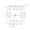
- twelve columnar electrodes 170 are arranged in a square shape along the outer edge of the holding plate 150.
- the number and position of the columnar electrodes 170 correspond to the number and position of the lands 100 of the substrate P to be mounted.
- the mounting substrate Ps is a substrate on which the columnar electrodes 170 and IC components are mounted on the substrate P.
- the manufacturing process of the mounting substrate Ps includes eight processes (A) to (H), and all are executed by the mounting apparatus 1.
- the board P is carried in and photographed. Specifically, the substrate P to be worked is subjected to printing processing (processing for printing the solder paste on the land on the surface of the substrate) in the upstream machine, and then to the work position G on the base 11 by the conveyor. Sent.
- the backup plate 26 of the backup device 25 rises to support the lower surface of the substrate P stopped at the work position G.
- the controller 210 moves the head unit 60 above the substrate P stopped at the work position G, and images the substrate P with the second camera 85.
- the columnar electrode 170 is taken out and inspected.
- the controller 210 moves the head unit 60 above the supply unit 13A. Then, the center of the upper surface of the holding plate 150 is sucked and held by the mounting head 63, and the holding plate 150 holding the columnar electrode 170 is taken out from the supply unit 13A.
- the controller 210 moves the head unit 60 above the first camera 81. Then, the holding plate 150 held by the mounting head 63 is photographed by the first camera 81.
- FIG. 9 is an image (corresponding to the first image of the present invention) 300 of the holding plate 150 photographed by the first camera 81.
- twelve white portions are high luminance portions (strong light reflection portions), and indicate columnar electrodes.
- the controller 210 confirms the adsorption state of the holding plate 150 by the mounting head 63, that is, the deviation of the adsorption position and the adsorption angle, from the image 300 of the holding plate 150.
- deviations dx and dy of the center O1 of the holding plate 150 with respect to the center O2 of the mounting head 63 and the inclination ⁇ of the holding plate 150 are detected.
- the shift amounts dx, dy and the inclination ⁇ are calculated in order to correct a shift in position and angle when the holding plate 150 is mounted on the substrate P.
- the center O1 of the holding plate 150 can be obtained from, for example, the intersection of straight lines Lx and Ly that recognize the outer shape of the holding plate 150 and connect the centers of the outer lines as shown in FIG. Further, the inclination ⁇ can be obtained from the inclination of the straight line Lx.
- controller 210 recognizes the columnar electrode 170 from the image 300 of the holding plate 150 and inspects whether the holding state of the columnar electrode 170 by the holding plate 150 is good.
- the inspection flow is composed of S10 to S120 as shown in FIG. 11, and the controller 210 firstly uses the column electrode 170 from the image 300 of the holding plate 150 photographed by the first camera 81.
- the process of recognizing is performed (S10).
- the controller 210 can recognize the columnar electrode 170 by analyzing the image of the holding plate 150 and recognizing it with high luminance.
- the controller 210 performs a process of confirming whether or not the columnar electrodes 170 are present at the electrode center positions C1 to C12 on the holding plate 150 (S20).
- the mounting apparatus 1 uses, as inspection data for each columnar electrode 170, data on the coordinates of electrode center positions C1 to C12 with reference to the center O1 of the holding plate 150; Data of a circular shape (for example, radius R) is stored in the storage unit 217.
- the controller 210 determines from the image 300 of the holding plate 150 photographed by the first camera 81 whether or not the columnar electrodes 170 overlapping the positions can be recognized for the electrode center positions C1 to C12.
- the controller 210 In addition to the columnar electrode 170 that overlaps the electrode center positions C1 to C12, A process for confirming whether or not the extra columnar electrodes 170 are recognized is performed (S30).
- the controller 210 performs a process of confirming whether there is an abnormality in the shape of each columnar electrode 170 overlapping the electrode center positions C1 to C12. (S40). Specifically, the outer shape of each columnar electrode 170 is recognized from the image 300 of the holding plate 150 photographed by the first camera 81, and the roundness and the circular dimension are checked. If the roundness or the circular dimension is within a normal range, it is determined that there is no abnormality. The roundness can be calculated from the circumference and area. The circular dimension is a radius R.
- the controller 210 performs a process of confirming whether there is any abnormality in the positions of the columnar electrodes 170 overlapping the electrode center positions C1 to C12. (S50). Specifically, the center position of each columnar electrode 170 is recognized from the image 300 of the holding plate 150 photographed by the first camera 81 with the center O1 of the holding plate 150 as a reference. Then, the recognized center position is compared with the electrode center positions C1 to C12 stored as inspection data, and if the position deviation is within a predetermined value, it is determined that there is no abnormality.
- the controller 210 determines that the holding state of the columnar electrodes 170 by the holding plate 150 is “normal” (S70). That is, it is determined that the regular number of columnar electrodes 170 are correctly arranged for each electrode center position C1 to C12 stored as inspection data.
- step (C) shown in FIG. 7 is performed.
- the controller 210 displays an error according to the type of error (details of error display will be described later) on the operation panel 220, and the holding plate 150 is not used for production and is treated as a repaired product (a product reused after repair).
- a plurality of columnar electrodes 170 held on the holding plate 150 are collectively mounted on the upper surface of the substrate P.
- the controller 210 moves the head unit 60 above the substrate P.
- the holding plate 150 moves right above the substrate P, the mounting head 63 is lowered, and a plurality of columnar electrodes 170 held on the holding plate 150 are collectively mounted on each land 100 of the substrate P.
- the controller 210 When there is a deviation in the suction position or suction angle of the holding plate 150 with respect to the mounting head 63, the controller 210 performs a correction process for correcting the position or angle deviation. Specifically, a process of correcting the mounting position is performed in consideration of the shift amounts dx and dy of the center O1. Further, the mounting head 63 is rotated in the R-axis direction to perform a process of correcting the inclination ⁇ .
- the mounted columnar electrode 170 and the land 100 of the substrate P are heat-bonded (reflowed).
- the controller 210 energizes the heater 27 built in the backup plate 26 and heats the substrate P.
- the solder paste printed on the lands 100 is dissolved, and the columnar electrodes 170 are collectively bonded to the lands 100 of the substrate P.
- the holding plate 100 is pulled away from the joined columnar electrode 170.
- the controller 210 raises the mounting head 63 from the height shown in FIG. 7D while maintaining the state where the holding plate 150 is adsorbed. Thereby, the holding plate 150 can be pulled away from the joined columnar electrode 170. That is, the holding plate 150 can be peeled against the adhesive force of the adhesive layer 155.
- the holding plate 100 is recognized and inspected. Specifically, the controller 210 moves the detached holding plate 150 above the first camera 81 and shoots.
- the controller 210 inspects the presence or absence of the columnar electrode 170 remaining on the holding plate 150 from the image 400 of the holding plate 150 taken by the first camera 81.
- FIG. 15 is an image obtained by photographing the holding plate 150 after being pulled away by the first camera 81, in which 400A shows a normal image and 400B shows an abnormal image.
- the images 400A and 400B correspond to the second image of the present invention.
- the controller 210 determines that all the columnar electrodes 170 held on the holding plate 150 are correctly mounted on the substrate P (normal). On the other hand, when the columnar electrodes 170 are recognized from the image of the holding plate 150 after the separation (in the case of the image 400B), it is determined that some of the columnar electrodes 170 held on the holding plate 150 are not mounted on the substrate P ( Abnormal).
- the holding plate 150 is discarded at a disposal place outside the figure, and then the process (G) shown in FIG. 8 is performed.
- the steps (G) and (H) shown in FIG. 8 are not executed, and the substrate P is handled as a defective product.
- step (G) shown in FIG. 8 a process for recognizing the position of the columnar electrode 170 mounted on the substrate P is performed. Specifically, the controller 210 moves the head unit 60 above the substrate P, and images the substrate P on which the columnar electrode 170 is mounted by the second camera 85. Then, the controller 210 recognizes the position of each columnar electrode 170 mounted on the substrate P from the image photographed by the second camera 85.
- a process of mounting the IC component 180 is performed. Specifically, the controller 210 moves the head unit 60 above the supply unit 13B. Then, the IC component 180 is taken out by the mounting head 63 from the supply unit 13B.
- the controller 210 photographs the IC component 180 held by the mounting head 63 with the first camera 81, and then controls the head unit 60 to mount the IC component 180 on the substrate P. That is, as shown in FIG. 8H, the IC component 180 is mounted so that the terminals 190 overlap each columnar electrode 170 bonded to the substrate P.
- the controller 210 executes a process of mounting an electronic component other than the IC component on the substrate P.
- the controller 210 executes a process of mounting an electronic component other than the IC component on the substrate P.
- the controller 210 performs a display corresponding to the type of error on the display unit (not shown) of the operation panel 220. .
- FIG. 13 shows the images 310A to 310E of the holding plate 150 taken by the first camera 81 when an error occurs.
- the image is shown in FIG.
- an image 330A in which an X mark is added to the electrode center position C2 is displayed on the operation panel 220, and together with this, “the column electrode is insufficient at the electrode center position C2. Repair work for replenishing the shortage is performed. Please go "message.
- the display is “an example of display teaching the repair method”.
- FIG. 14B As shown in an image 310B in FIG. 13B, when a part of the electrode center position C9 is abnormal in the shape of the columnar electrode 170 that overlaps the position (S40: NO), it is shown in FIG. 14B.
- an image 330B in which an X mark is added to the electrode center position C9 is displayed on the operation panel 220, and together with this, “the columnar electrode at the electrode center position C9 is tilted. Perform repair work to repair the tilt. Please display a message such as "Please".
- the display is “an example of display teaching the repair method”.
- FIG. 14C As shown in the image 310C of FIG. 13C, when there is an abnormality in the position of the columnar electrode 170 that overlaps the electrode center position C2 (S50: NO), it is shown in FIG. 14C. As described above, an image 330C in which an X mark is added to the electrode center position C2 is displayed on the operation panel 220, and together with this, “the position of the columnar electrode at the electrode center position C2 is shifted. Repair for correcting the position shift” Please do the work "message. The display is “an example of display teaching the repair method”.
- an image 310E shown in FIG. 13E shows a case where the holding plate 150 is taken out from the supply unit 13A in a state where two sheets overlap each other.
- a NO determination is made in S60 of the inspection flow, and thereafter, as shown in FIG. 14E, an image 330E in which an X mark is added to one holding plate 150 is displayed on the operation panel 220, and this is combined. Display a message such as "The holding plate is being sucked at the same time. Please perform repair work to remove the holding plate that has been picked up at the same time.”
- the display is “an example of display teaching the repair method”.
- the mounting plate 150 recognizes an image of the holding plate 150 and inspects whether the holding state of the columnar electrode 170 by the holding plate 150 is good (step (B) in FIG. 8). Then, only when there is no abnormality as a result of the inspection, the columnar electrodes 170 held on the holding plate 150 are collectively mounted on the substrate P. Therefore, since it is possible to avoid the holding plate 150 having an abnormality in holding the columnar electrode 170 from being used for production, it is possible to suppress the manufacture of defective substrates.
- the holding state of the columnar electrode 170 is inspected using the image 300 acquired in order to confirm the suction state of the holding plate 150 with respect to the mounting head 63 (presence or absence of center position deviation or inclination). Therefore, it is not necessary to photograph the holding plate 150 for inspection of the holding state of the columnar electrode 170.
- the mounting apparatus 1 recognizes the image of the holding plate 150 and inspects the presence or absence of the columnar electrode 170 remaining on the holding plate 150.
- the IC component 180 is mounted on the substrate P.
- the substrate P is handled as a defective product. By doing in this way, the outflow of a defective board
- the mounting apparatus 1 when there is an abnormality in the holding state of the columnar electrode 170 by the holding plate 150, the mounting apparatus 1 performs a display that teaches a repair method according to the type of abnormality. By doing in this way, an operator can perform the repair work of the columnar electrode 170 easily.
- the controller 210 performs a process of inspecting whether the columnar electrode 170 is mounted on the substrate P. Specifically, in the step (A) shown in FIG. 7, an image obtained by photographing the substrate P with the second camera 85 before the columnar electrodes 170 are collectively mounted, and in the step (G) shown in FIG. As an example of a method for comparing two images from an image obtained by shooting the substrate P with the second camera 85 after mounting 170, a difference image between the two images is created.
- FIG. 16A is an image obtained by photographing the substrate P with the second camera 85 before the columnar electrodes 170 are collectively mounted (corresponding to the fourth image of the present invention).
- An image 520 shown in FIG. 16B is an image (corresponding to the third image of the present invention) obtained by photographing the substrate P with the second camera 85 after the columnar electrode 170 is mounted.
- An image 530 shown in FIG. 16C is a difference image between the two images 510 and 520.
- the difference image 530 is an image in which a portion that does not change before and after mounting, such as a wiring pattern, disappears and only the portion that has changed remains, so that the columnar electrode 170 is easy to recognize, and whether the columnar electrode 170 is mounted on the substrate P is good or bad. Can be accurately determined.
- FIG. 16 is a normal image, and the 12 columnar electrodes 170 are mounted on the substrate P without mistake.
- FIG. 17 shows images 510 to 520 at the time of poor mounting. As is clear from the difference image 530, only 11 columnar electrodes 170 are mounted on the substrate P, and the unmounted columnar electrodes 170 are not mounted. Existing.
- the controller 210 recognizes the columnar electrode 170 from the difference image 530 and determines whether the mounting failure is good or bad. Then, when normal, the process proceeds to step (H) shown in FIG. 8, and the work of mounting the IC component 180 on the substrate P on which the columnar electrode 170 is mounted is performed. On the other hand, when there is a mounting failure of the columnar electrode 170, the substrate P is processed as a defective product.
- the method for inspecting the quality of the mounting state of the columnar electrode 170 on the substrate P can be performed by the same method as the method for inspecting the quality of the holding state of the columnar electrode 170 by the holding plate 150.
- FIG. 18 is a plan view of the mounting apparatus 1 according to the third embodiment.
- the third embodiment is different from the first embodiment in that a laser displacement meter 600 is added.
- the laser displacement meter 600 is an example of the “first detector” in the present invention.
- the laser displacement meter 600 is a device that measures the height of the lower surface 171 of the columnar electrode 170 held by the holding plate 150.
- the lower surface 171 is a bonding surface with respect to the substrate P.
- the laser displacement meter 600 is arranged on the base 11 with the detection surface facing upward.
- the controller 210 takes an image of the holding plate 150 with the first camera 81 in the process of FIG. 7B, and then moves the holding plate 150 above the laser displacement meter 600 to hold the holding plate.
- the height H of the lower surface 171 of each columnar electrode 170 held at 150 is measured by a laser displacement meter 600.
- the laser displacement meter 600 uses so-called triangulation, and has a light projecting unit that emits a laser and a light receiving unit that receives a laser reflected by an object.
- the laser displacement meter 600 measures the height H of the lower surface 171 of each columnar electrode 170 with the lower surface of the holding plate 150 as a reference.
- the controller 210 determines whether or not the height H of the lower surface 171 is good, that is, whether the height H is uneven or not, for each columnar electrode 170 based on the measurement result. Specifically, the average of the heights H of all the columnar electrodes 170 is calculated. Then, for each columnar electrode 170, the difference of the height H with respect to the average is obtained. When the obtained difference is smaller than the threshold value, the height H is determined to be “normal”, and when the difference from the average is larger than the threshold value, “ It is judged as “abnormal”.
- the controller 210 When all the columnar electrodes 170 are “normal”, the controller 210 collectively mounts the columnar electrodes 170 on the substrate P as shown in FIG.
- the holding plate 150 is handled as a repair product and is not used for production.
- the mounting defect of the columnar electrode 170 due to the variation in the height H at the time of mounting on the substrate P can be suppressed.
- the production of defective substrates can be suppressed.
- the mounting target of the columnar electrode 170 is not limited to the substrate P, and may be a component such as an IC. That is, the columnar electrode 170 may be mounted on a component such as an IC.
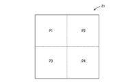
- the substrate P may be a collective substrate Pr composed of a plurality of small substrates P1 to P4 as shown in FIG.
- the columnar electrode groups G1 to G4 corresponding to the small substrates P1 to P4 are collectively held by the holding plate 150 by the number of the small substrates.
- a plurality of columnar electrode groups G1 to G4 may be collectively mounted on the small substrates P1 to P4 of the collective substrate Pr using the holding plate 150.
- the substrate P is heated from below by the heater 27 built in the backup plate 26 to join the land 100 of the substrate P and the columnar electrode 170 (hereinafter, reflow process). )did. Then, after the bonding, a step of separating the holding plate 150 from the columnar electrode 170 bonded to the substrate P was performed.
- the separation of the holding plate 150 can be performed if the mounted columnar electrode 170 is fixed to the substrate P by any means. Therefore, the reflow process may be performed after the holding plate 150 is separated from the columnar electrode 170. Furthermore, the reflow process and the IC component 180 mounting process may be performed by another apparatus disposed on the downstream side of the mounting apparatus 1. That is, the mounting device 1 may be any device that performs a process of mounting the columnar electrode 170 on the substrate P using at least the holding plate 150.
- a method for fixing the columnar electrode 170 and the land 100 there is a method using an ultraviolet curable resin agent. That is, a curable resin agent is applied in advance to the land 100 of the substrate P. Then, after the columnar electrode 170 is mounted on the substrate P, for example, the adhesive is cured by irradiating ultraviolet rays from an ultraviolet irradiation device provided in the head unit 60. Thereby, the columnar electrode 170 can be fixed to the land 100 of the substrate P.
- coating of a resin agent can be performed with an upstream machine, for example, before carrying in the board
- the holding plate 150 is separated from the columnar electrode 170 mounted on the substrate P using the mounting head 63 of the head unit 60 .
- the separation of the holding plate 150 is not necessarily performed using the mounting head 63, and may be performed by providing a dedicated separating device.
- the separation device may be any structure that can be pulled upward with the holding plate 150 fixed, and the installation location is not limited to the mounting device 1. That is, it may be installed in the mounting device 1 or may be provided separately from the mounting device 1.
- the holding plate 150 is photographed by the first camera 81, and the columnar shape left on the holding plate 150 from the obtained images 400A and 400B. Although the presence or absence of the electrode 170 was inspected, this inspection is optional.
- the columnar electrode 170 has a cylindrical shape, but may have a prismatic shape.
- the quality of the mounting state of the columnar electrode 170 on the substrate P was inspected based on the difference image 530 of the substrate P before and after the columnar electrode 170 was mounted.
- whether or not the columnar electrode 170 is mounted on the substrate P may be inspected based only on the image 520 obtained by photographing the substrate P with the second camera 85 after the columnar electrode 170 is mounted. .
- the laser displacement meter 600 is provided on the base 11 and the height of the lower surface 171 of the columnar electrode 170 held by the holding plate 150 is measured.
- a laser displacement meter may be separately provided to measure the height of the upper surface 172 of the columnar electrode 170 mounted on the substrate P.
- the upper surface 172 is a mounting surface of the IC component 180 which is a counterpart component.
- the laser displacement meter 700 is provided with the detection surface directed downward with respect to the head unit 60.
- the laser displacement meter 700 is an example of the “second detection unit” in the present invention.
- the controller 210 inspects the presence or absence of the columnar electrode 170 remaining on the holding plate 150 in the step (F) of FIG. 8 after separating the holding plate 150 from the columnar electrode in the step of (E) of FIG. To do.
- the controller 210 moves the head unit 60 above the substrate P, and sets the height of the upper surface 171 of each columnar electrode 170 mounted on the substrate P to the laser. Measurement is performed by a displacement meter 700. For example, the height of the upper surface 171 may be measured based on the upper surface of the substrate P.
- the controller 210 determines whether or not the height of the upper surface 172 of each columnar electrode 170 is good, that is, whether or not the height varies, based on the measurement result.
- the method for determining the variation in height is the same as that in the third embodiment.
- the controller 210 places the IC as a counterpart component on the substrate P on which the columnar electrodes 170 are mounted. A component 180 is mounted.
- the substrate P is handled as a defective substrate and is not used for subsequent production.
- the mounting state of the columnar electrode 170 is inspected based on the difference image 530 described in the second embodiment, and both the two inspections are normal.
- the IC component 180 may be mounted on the substrate P on which the columnar electrode 170 is mounted by performing the process of FIG.
- the laser displacement meters 600 and 700 can be substituted by a stereo camera or the like that photographs an object simultaneously from a plurality of different directions.
- Embodiment 1 shows an example in which the columnar electrode 170 is held on the holding plate 150 using the adhesive layer 155.
- the holding method may be mechanical holding such as hooks and nails, for example, in addition to adhesion.
Landscapes
- Engineering & Computer Science (AREA)
- Biochemistry (AREA)
- General Physics & Mathematics (AREA)
- Physics & Mathematics (AREA)
- Health & Medical Sciences (AREA)
- Life Sciences & Earth Sciences (AREA)
- Chemical & Material Sciences (AREA)
- Microelectronics & Electronic Packaging (AREA)
- Analytical Chemistry (AREA)
- General Health & Medical Sciences (AREA)
- Manufacturing & Machinery (AREA)
- Immunology (AREA)
- Pathology (AREA)
- Investigating Materials By The Use Of Optical Means Adapted For Particular Applications (AREA)
- Electric Connection Of Electric Components To Printed Circuits (AREA)
- Structures For Mounting Electric Components On Printed Circuit Boards (AREA)
- Supply And Installment Of Electrical Components (AREA)
Abstract
検査装置5であって、保持体150を用いて複数の柱状電極170を基板上又は部品上に一括搭載する搭載装置1に設けられ、前記保持体150を撮影する第1カメラ81と、前記第1カメラ81により一括搭載前に撮影された前記保持体150の第1画像に基づいて、前記保持体150による柱状電極170の保持状態の良否を判断する判断部210と、を備える。
Description
本明細書で開示される技術は、柱状電極の状態を検査する技術に関する。
従来から、基板と電子部品との電気的接続や、電子部品と電子部品との電気的接続に柱状電極を用いたものがある。柱状電極は、半田ボールを用いた接続に比べて、占有面積が小さいことから、端子を高密度で配置することが可能であり、LSIなど電子部品の高集積化に適している。
下記特許文献1には、半導体基板と、半導体基板の主面に形成された電極パットと、電極パットと電気的に接続された突起電極とを有し、突起電極は、電極パット上に設けられた台座部と、台座部上に設けられた突起部を備える半導体装置が記載されている。同文献にでは、積層技術を用いて半導体基板上に突起電極を形成している。
基板や部品に対して柱状電極(突起電極)を設ける工法として、積層技術以外に下記の方法が考えられる。図5に示すように、保持体(保持プレート)の下面に対して、例えば、粘着層などを用いて、柱状電極を所定の配列で保持しておく。そして、柱状電極を保持体に保持したまま、移載して、基板や部品上の搭載位置に搭載する。その後、柱状電極を基板や部品に対して固定してから、保持体を引き離すことで、基板や部品に対して柱状電極を取り付けることが出来る。
保持体を用いた工法では、柱状電極の配置の変更が比較的容易であるというメリットがある。しかしながら、保持体に対して余分な柱状電極が保持されている場合や不足分がある場合、基板や部品へ搭載される柱状電極に過不足が生じることから、製造不良となる。
本明細書で開示される技術は、基板や部品に保持体を用いて柱状電極を搭載する場合に、保持体による柱状電極の保持状態の良否を検査することにより、不良基板の製造を抑制することを目的とする。
本明細書で開示される技術は、基板や部品に保持体を用いて柱状電極を搭載する場合に、保持体による柱状電極の保持状態の良否を検査することにより、不良基板の製造を抑制することを目的とする。
本明細書で開示される検査装置は、保持体を用いて複数の柱状電極を基板上又は部品上に一括搭載する搭載装置に設けられ、前記保持体を撮影する第1カメラと、前記第1カメラにより一括搭載前に撮影された前記保持体の第1画像に基づいて、前記保持体による前記柱状電極の保持状態の良否を判断する判断部と、を備える。本構成では、保持体による柱状電極の保持状態の良否を検査できる。
本明細書で開示される検査装置の一実施態様として、前記判断部は、前記保持体による前記柱状電極の保持状態に異常がある場合、検査対象の前記保持体について、異常の種類に応じたリペア方法を教示する表示を行うとよい。この構成では、作業者が、柱状電極のリペア作業を容易に行うことが出来る。
本明細書で開示される検査装置の一実施態様として、前記保持体による前記柱状電極の保持状態が正常な場合、前記保持体を用いて複数の前記柱状電極を前記基板上又は前記部品上に一括搭載して固定した後、引離装置によって前記保持体を前記柱状電極から引き離すとよい。この構成では、保持体による柱状電極の保持状態が正常な場合に、基板上又は部品上に柱状電極を一括搭載する工程や、一括搭載した柱状電極から保持体を引き離す工程を行うので、不良基板の発生を抑制できる。
本明細書で開示される検査装置の一実施態様として、前記判断部は、前記柱状電極から引き離した前記保持体を、前記第1カメラにより撮影した第2画像に基づいて、搭載されずに、前記保持体に残された前記柱状電極の有無を判断するとよい。この構成では、基板又は部品に対する柱状電極の固定不良を検出することが出来る。そのため、不良基板や不良部品の流出を抑制できる。
本明細書で開示される検査装置の一実施態様として、前記基板又は前記部品を撮影する第2カメラを備え、前記判断部は、前記保持体の引き離し後、前記柱状電極が固定された前記基板又は前記部品を前記第2カメラにより撮影した第3画像に基づいて、前記基板又は前記部品に対する前記柱状電極の搭載状態の良否を判断するとよい。この構成では、基板又は部品に対する柱状電極の搭載不良を検出することが出来る。そのため、不良基板や不良部品の流出を抑制できる。
本明細書で開示される検査装置の一実施態様として、前記判断部は、前記第3画像と、前記柱状電極の一括搭載前に前記基板又は前記部品を前記第2カメラにより撮影した第4画像とを比較することにより、前記基板又は前記部品に対する前記柱状電極の搭載状態の良否を判断するとよい。この構成では、搭載前後の画像を比較するので、配線パターンなどの影響を受けることなく、基板又は部品に対する柱状電極の搭載不良を精度よく検出することが出来る。
本明細書で開示される検査装置の一実施態様として、前記保持体に保持された前記柱状電極の下面の高さを検出する第1検出部を備え、前記判断部は、前記第1検出部の検出値に基づいて、前記保持体に保持された複数の前記柱状電極について、前記下面の高さの良否を判断するとよい。この構成では、柱状電極の下面の高さ不良に起因する、柱状電極の搭載不良を抑制することが出来る。
本明細書で開示される検査装置の一実施態様として、前記基板上又は前記部品上に搭載された前記柱状電極の上面の高さを検出する第2検出部を備え、前記判断部は、前記第2検出部の検出値に基づいて、前記基板又は前記部品上に搭載された複数の前記柱状電極について、前記上面の高さの良否を判断するとよい。この構成では、柱状電極の上面の高さ不良に起因する、相手部品の搭載不良を抑制することが出来る。
本明細書で開示される搭載装置は、基板上又は部品上に柱状電極を搭載する搭載装置であって、基台と、保持体を用いて複数の前記柱状電極を前記基板上又は前記部品上に一括搭載するヘッド部と、上記検査装置を備える。本構成では、搭載装置は、保持体による柱状電極の保持状態の良否を検査する検査装置を備えているので、不良基板の発生を抑制できる。
本明細書で開示する搭載装置の一実施態様として、前記検査装置は、前記搭載装置に設けられた第1カメラにより一括搭載前に撮影された前記保持体の第1画像に基づいて、前記保持体による前記柱状電極の保持状態の良否を判断し、前記ヘッド部は、前記保持体よる前記柱状電極の保持状態が正常な場合、前記基板上又は前記部品上に一括搭載された前記柱状電極から前記保持体を引き離すとよい。本構成では、搭載装置にて、柱状電極を一括搭載する工程と、保持体を引き離す工程を行うことが出来る。また、保持体による柱状電極の保持状態が正常な場合に、柱状電極を一括搭載する工程や、保持体を引き離す工程を行うので、不良基板の発生を抑制できる。
本明細書で開示される検査方法は、保持体を用いて複数の柱状電極を基板上又は部品上に一括搭載する搭載装置に設けられた第1カメラで、前記保持体を、一括搭載前に撮影し、前記第1カメラにより撮影した前記保持体の第1画像に基づいて、前記保持体による前記柱状電極の保持状態の良否を判断する。本方法では、保持体による柱状電極の保持状態の良否を検査できる。
本明細書で開示される技術によれば、保持体に保持された柱状電極の状態を検査できる。そして、検査により正常と判定された保持体を生産に使用することで、不良基板の製造を抑制することが出来る。
<実施形態1>
1.搭載装置1の全体構成
搭載装置1は、図1に示すように、基台11と、基板Pを搬送する搬送コンベア20と、バックアップ装置25と、ヘッドユニット60と、ヘッドユニット60を基台11上にて平面方向(XY方向)に移動させる駆動装置30と、第1カメラ81と、第2カメラ85を備えている。尚、以下の説明において、基台11の長手方向(図1の左右方向)をX方向と呼ぶものとし、基台11の奥行方向(図1の上下方向)をY方向、図2の上下方向をZ方向とする。また、ヘッドユニット60が、本発明の「ヘッド部」、「引離装置」の一例である。
1.搭載装置1の全体構成
搭載装置1は、図1に示すように、基台11と、基板Pを搬送する搬送コンベア20と、バックアップ装置25と、ヘッドユニット60と、ヘッドユニット60を基台11上にて平面方向(XY方向)に移動させる駆動装置30と、第1カメラ81と、第2カメラ85を備えている。尚、以下の説明において、基台11の長手方向(図1の左右方向)をX方向と呼ぶものとし、基台11の奥行方向(図1の上下方向)をY方向、図2の上下方向をZ方向とする。また、ヘッドユニット60が、本発明の「ヘッド部」、「引離装置」の一例である。
搬送コンベア20は、基台11の中央に配置されている。搬送コンベア20はX方向に循環駆動する一対の搬送ベルト21を備えており、搬送ベルト21上の二点鎖線で示した基板Pを、ベルトとの摩擦によりX方向に搬送する。
本実施形態では、図1に示す左側が入り口となっており、基板Pは、図1に示す左側より搬送コンベア20を通じて上流機から基台11上へ搬入される。搬入された基板Pは、搬送コンベア20により基台中央の作業位置Gまで運ばれ、そこで停止される。
作業位置Gには、バックアップ装置25が設けられている。バックアップ装置25は、図2に示すように、基板Pの下面を支えるバックアッププレート26と昇降装置28を有している。バックアッププレート26は、昇降装置28により、Z方向に移動することが出来る。バックアップ装置25は、作業位置Gにて基板Pの下面を支えることで、搭載時に基板Pが撓むように変形することを抑制する。
また、バックアッププレート26には、加熱用のヒータ27が内蔵されていてもよい。ヒータ27は、柱状電極170を基板Pのランド100に加熱接合(リフロー)するために設けられている。尚、図2において、バックアップ装置25、基板P、コンベア20は、X方向から見た図としてある。
基台11上には、作業位置Gの周囲を囲むようにして、供給部13A~13Cが設けらている。供給部13Aには、後述する柱状電極170を保持した保持プレート150が配置されている。供給部13Bには、LSIチップ等のIC部品180が配置されている。また、供給部13Cには、チップ抵抗などの小型電子部品を供給するフィーダが横並び状に多数設置されている。
そして、作業位置Gでは、供給部13A~13Cに配置された各パーツ、すなわち柱状電極170、IC部品180、小型電子部品を、基板P上に搭載する搭載処理が、ヘッドユニット60に搭載された搭載ヘッド63により行われる。尚、搭載装置1での全工程を終えた実装基板Psはコンベア20を通じて、図1における右方向に運ばれ、下流機に搬出される構成になっている。尚、実装基板Psは、上流機から搬入された基板Pに対して柱状電極170やIC部品180、小型部品などの必要なパーツを搭載した基板を意味する。
駆動装置30は、大まかには一対の支持脚41、ヘッド支持体51、Y軸ボールネジ45、Y軸モータ47、X軸ボールネジ55、X軸モータ57から構成される。具体的に説明してゆくと、図1に示すように基台11上には一対の支持脚41が設置されている。両支持脚41は作業位置の両側に位置しており、共にY方向にまっすぐに延びている。
両支持脚41にはY方向に延びるガイドレール42が支持脚上面に設置されると共に、これら左右のガイドレール42に長手方向の両端部を嵌合させつつヘット支持体51が取り付けられている。
また、右側の支持脚41にはY方向に延びるY軸ボールねじ45が装着され、更にY軸ボールねじ45にはボールナット(不図示)が螺合されている。そして、Y軸ボールねじ45にはY軸モータ47が付設されている。
Y軸モータ47を通電操作すると、Y軸ボールねじ45に沿ってボールナットが進退する結果、ボールナットに固定されたヘッド支持体51、ひいては次述するヘッドユニット60がガイドレール42に沿ってY方向に移動する(Y軸サーボ機構)。
ヘッド支持体51は、X方向に長い形状である。ヘッド支持体51には、図2に示すように、X方向に延びるガイド部材53が設置され、更に、ガイド部材53に対してヘッドユニット60が、ガイド部材53の軸に沿って移動自在に取り付けられている。このヘッド支持体51には、X方向に延びるX軸ボールねじ55が装着されており、更にX軸ボールねじ55にはボールナットが螺合されている。
そして、X軸ボールねじ55にはX軸モータ57が付設されており、同モータ57を通電操作すると、X軸ボールねじ55に沿ってボールナットが進退する結果、ボールナットに固定されたヘッドユニット60がガイド部材53に沿ってX方向に移動する(X軸サーボ機構)。
従って、X軸モータ57、Y軸モータ47を複合的に制御することで、基台11上においてヘッドユニット60を平面方向(XY方向)に移動操作出来る構成となっている。
係るヘッドユニット60には、各パーツの搭載作業を行う搭載ヘッド63が列をなして複数個搭載されている。各搭載ヘッド63はR軸モータによる軸回りの回転と、Z軸モータの駆動によりヘッドユニット60に対して昇降可能な構成となっている。また、各搭載ヘッド63には図外の負圧手段から負圧が供給されるように構成されており、ヘッド先端に吸引力を生じさせるようになっている。
搭載装置1は、X軸モータ57、Y軸モータ47、Z軸モータを所定のタイミングで作動させることにより、供給部13A~13Cから各パーツ、すなわち柱状電極170、IC部品180、小型電子部品を、搭載ヘッド63により取り出して、基板P上に搭載する処理を実行することが出来る。
基台11上には、第1カメラ81が設置されている。第1カメラ81は、基台11上において撮像面を上に向けて固定されている。第1カメラ81は、各供給部13A~13Cから取り出した保持プレート150やIC部品180などを画像認識するために設けられている。
また、ヘッドユニット60には、撮像面を下に向けた状態で、第2カメラ85が固定されている。第2カメラ85は、上述のX軸サーボ機構、Y軸サーボ機構を駆動させることで、基台11上をヘッドユニット60と一体的に移動することから、基板P上の任意の位置の画像を撮像することが出来る。搭載装置1は、第2カメラ85により撮影した基板Pの画像に基づいて、作業位置Gに停止した基板Pの位置や、基板P上に形成された各ランド100の位置を認識する。
2.搭載装置1の電気的構成
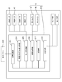
次に、搭載装置1の電気的構成を、図3を参照して説明する。搭載装置1はコントローラ210により装置全体が制御統括されている。尚、コントローラ210は、本発明の「判断部」の一例である。また、コントローラ210、第1カメラ81、第2カメラ85が、「検査装置5」である。
次に、搭載装置1の電気的構成を、図3を参照して説明する。搭載装置1はコントローラ210により装置全体が制御統括されている。尚、コントローラ210は、本発明の「判断部」の一例である。また、コントローラ210、第1カメラ81、第2カメラ85が、「検査装置5」である。
コントローラ210はCPU等により構成される演算処理部211を備える他、搭載プログラム記憶手段213、モータ制御部215、画像処理部216、記憶部217、入出力部219を設けている。演算処理部211には、操作パネル220が接続されていて、操作パネル220を介して、各種の入力操作ができるようになっている。
搭載プログラム記憶手段213には、X軸モータ57、Y軸モータ47、Z軸モータ、R軸モータなどからなるサーボ機構を制御するための搭載プログラムが格納されている。
モータ制御部215は演算処理部211と共に、搭載プログラムに従って各種モータを駆動させるものであり、同モータ制御部215には、各種モータが電気的に連なっている。
また、画像処理部216には、第1カメラ81、第2カメラ85が電気的に連なっており、これら各カメラ81、85から出力される画像データがそれぞれ取込まれるようになっている。そして、画像処理部216では、取り込まれた画像の解析が行われる。
3.基板Pに対する柱状電極170の搭載と検査工程
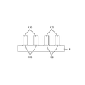
柱状電極170は、図4に示すように基板Pのランド100上に搭載され、IC部品180との接続用の端子として機能する。
柱状電極170は、図4に示すように基板Pのランド100上に搭載され、IC部品180との接続用の端子として機能する。
搭載装置1は、図5、6に示す保持プレート150を用いて、基板Pに対して複数の柱状電極170を一括搭載する。尚、保持プレート150が本発明の「保持体」の一例である。
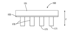
保持プレート150は、図5に示すように、平板状をなす樹脂製のプレート本体151と、プレート本体151の下面に設けられた粘着層155とから構成されている。
柱状電極170は、銅製であって、円柱形状である。柱状電極170は、保持プレート150の粘着層155により保持されている。具体的には、柱状電極170は、保持プレートの粘着層155に上面を突き当てており、保持プレート150に対して直立した状態(軸線を直交させた状態)に保持されている。柱状電極170の下面171は、基板Pへの接合面である。
図6に示すように、保持プレート150には、複数の柱状電極170が所定の配列で粘着保持されている。図6の例では、保持プレート150に対して、12個の柱状電極170が、プレート外縁に沿って四角形状に配置されている。柱状電極170の数と位置は、搭載対象となる基板Pのランド100の数と位置に対応している。
図7、図8は、実装基板Psの製造工程を示す図である。実装基板Psは、基板Pに対して柱状電極170やIC部品を搭載した基板である。
実装基板Psの製造工程は、(A)~(H)の8つの工程から構成されており、全て搭載装置1にて実行される。
(A)の工程では、基板Pの搬入及び撮影が行われる。具体的には、作業対象となる基板Pは、上流機にて印刷処理(基板表面のランド上にゾルダペーストを印刷する処理)を行った後、コンベアにより、基台11上の作業位置Gに送られる。
その後、バックアップ装置25のバックアッププレート26が上昇して、作業位置Gに停止した基板Pの下面を支える。基板Pの搬入後、コントローラ210は、作業位置Gに停止した基板Pの上方にヘッドユニット60を移動し、基板Pを第2カメラ85により、撮影する。
(B)の工程では、柱状電極170の取り出し及び検査が行われる。具体的には、コントローラ210は、供給部13Aの上方にヘッドユニット60を移動する。そして、保持プレート150の上面の中央を搭載ヘッド63により吸着保持し、供給部13Aから柱状電極170を保持した保持プレート150を取り出す。
その後、コントローラ210は、第1カメラ81の上方にヘッドユニット60を移動する。そして、搭載ヘッド63により保持した保持プレート150を、第1カメラ81により、撮影する。
図9は、第1カメラ81により撮影した保持プレート150の画像(本発明の第1画像に相当)300である。尚、画像300のうち、12個の白い部分は輝度が高い部分(光の反射が強い部分)であり、柱状電極を示している。
コントローラ210は、保持プレート150の画像300から、搭載ヘッド63による保持プレート150の吸着状態、すなわち吸着位置や吸着角度のずれを確認する。
具体的には、図10に示すように、搭載ヘッド63の中心O2に対する保持プレート150の中心O1のずれ量dx、dyと、保持プレート150の傾きθを検出する。ずれ量dx、dyと傾きθは、保持プレート150を基板Pに搭載する際に、位置や角度のずれを補正するために算出している。
尚、保持プレート150の中心O1は、例えば、図10に示すように、保持プレート150の外形を認識し、外形線の中心を結ぶ直線Lx、Lyの交点から求めることが出来る。また、傾きθは、直線Lxの傾きから求めることが出来る。
また、コントローラ210は、保持プレート150の画像300から、柱状電極170を認識し、保持プレート150による柱状電極170の保持状態の良否を検査する。
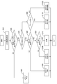
具体的に説明すると、検査フローは、図11に示すように、S10~S120から構成されており、コントローラ210は、まず、第1カメラ81により撮影した保持プレート150の画像300から、柱状電極170を認識する処理を行う(S10)。
保持プレート150の画像300は、図9に示すように、柱状電極170の部分だけが白く光り(輝度が高い)、周囲は概ね暗い画像となる。そのため、コントローラ210は、保持プレート150の画像を解析して、輝度の高い認識することで、柱状電極170を認識することが出来る。
次に、コントローラ210は、保持プレート150上の電極中心位置C1~C12に、柱状電極170が全てあるか、確認する処理を行う(S20)。
具体的には、搭載装置1は、図12に示すように、各柱状電極170の検査用データとして、保持プレート150の中心O1を基準とした、電極中心位置C1~C12の座標のデータと、円形状(例えば半径R)の大きさのデータを、記憶部217に保持している。
そして、コントローラ210は、第1カメラ81により撮影した保持プレート150の画像300から、各電極中心位置C1~C12について、その位置に重なる柱状電極170が認識できているか、判定する。
全ての電極中心位置C1~C12について、その位置に重なる柱状電極170が認識できている場合(S20:YES)、コントローラ210は、電極中心位置C1~C12に対して重なる柱状電極170の他に、余分な柱状電極170を認識していないか、確認する処理を行う(S30)。
余分な柱状電極170を認識していない場合(S30:YES)は、コントローラ210は、電極中心位置C1~C12に対して重なる各柱状電極170について、形状の異常はないか、確認する処理を行う(S40)。具体的には、第1カメラ81により撮影した保持プレート150の画像300から各柱状電極170の外形を認識し、真円度や円形寸法をチェックする。そして、真円度や円形寸法が正常範囲であれば、異常なしと判断する。尚、真円度は周長と面積から算出することが出来る。また、円形寸法は半径Rである。
全ての柱状電極170について形状の異常がない場合(S40:YES)、コントローラ210は、電極中心位置C1~C12に対して重なる各柱状電極170について、位置の異常はないか、確認する処理を行う(S50)。具体的には、第1カメラ81により撮影した保持プレート150の画像300から、保持プレート150の中心O1を基準として、各柱状電極170の中心位置を認識する。そして、認識された中心位置と、検査データとして記憶されている電極中心位置C1~C12とを比較し、位置のずれが所定値以内であれば、異常なしと判断する。
全ての柱状電極170について位置の異常がない場合(S50:YES)、コントローラ210は、保持プレート150による柱状電極170の保持状態は「正常」と判断する(S70)。すなわち、検査用データとして記憶されている各電極中心位置C1~C12に対して、柱状電極170が正規の数だけ正しく配置されていると判断する。
そして、保持プレート150による柱状電極170の保持状態は、正常と判断した場合、図7に示す(C)の工程が行われる。
一方、検査フローにおいて、S20~S50でNO判定された場合、コントローラ210は、操作パネル220に対して、エラーの種類に応じたエラー表示(エラー表示の詳細は後述する)を行い、当該保持プレート150は、生産に使用せず、リペア品(修復後、再使用品)として扱われる。
図7に示す(C)の工程では、保持プレート150に保持された複数の柱状電極170を基板Pの上面に一括搭載する。具体的には、コントローラ210は、基板Pの上方に、ヘッドユニット60を移動する。そして、保持プレート150が基板Pの真上まで移動すると、搭載ヘッド63を下降し、保持プレート150上に保持された複数の柱状電極170を、基板Pの各ランド100上に一括搭載する。
尚、搭載ヘッド63に対する保持プレート150の吸着位置や吸着角度にずれがある場合、コントローラ210は、位置や角度のずれを補正する補正処理を行う。具体的には、中心O1のずれ量dx、dyを見込んで、搭載位置を補正する処理を行う。また、搭載ヘッド63をR軸方向に回転し、傾きθを補正する処理を行う。
図7に示す(D)の工程では、搭載された柱状電極170と基板Pのランド100が加熱接合(リフロー)される。具体的には、コントローラ210は、バックアッププレート26に内蔵されたヒータ27を通電し、基板Pを加熱する。これにより、ランド100上に印刷されたゾルダペーストが溶解し、基板Pの各ランド100に柱状電極170が一括して接合される。
図8に示す(E)の工程では、接合した柱状電極170から、保持プレート100が引き離される。具体的には、コントローラ210は、保持プレート150を吸着した状態を維持したまま、図7の(D)に示す高さから搭載ヘッド63を上昇する。これにより、接合された柱状電極170から保持プレート150を引き離すことが出来る。すなわち、粘着層155の粘着力に抗して、保持プレート150を剥離することが出来る。
図8に示す(F)の工程では、保持プレート100の認識及び検査が行われる。具体的には、コントローラ210は、引き離した保持プレート150を、第1カメラ81の上方に移動して撮影する。
そして、コントローラ210は、第1カメラ81により撮影した保持プレート150の画像400から、保持プレート150上に残されている柱状電極170の有無を検査する。
図15は、引き離し後の保持プレート150を第1カメラ81により撮影した画像であり、400Aは正常時の画像、400Bは異常時の画像を示している。尚、画像400A、400Bが本発明の第2画像に相当する。
引き離し後の保持プレート150の画像から柱状電極170が認識されない場合(画像400Aの場合)、コントローラ210は、保持プレート150に保持された全ての柱状電極170は基板Pに正しく搭載されたと判断する(正常)。一方、引き離し後の保持プレート150の画像から柱状電極170が認識される場合(画像400Bの場合)、保持プレート150に保持された一部の柱状電極170が基板Pに搭載されなかったと判断する(異常)。
そして、「正常」と判断した場合、保持プレート150を図外の廃棄場所に廃棄した後、図8に示す(G)の工程が行われる。尚、「異常」と判断した場合、図8に示す(G)、(H)の工程は実行されず、当該基板Pは不良品として扱われる。
図8に示す(G)の工程では、基板P上に搭載された柱状電極170の位置を認識する処理が行われる。具体的には、コントローラ210は、基板Pの上方にヘッドユニット60を移動して、柱状電極170を搭載した基板Pを第2カメラ85により撮影する。そして、コントローラ210は、第2カメラ85により撮影された画像から、基板P上に搭載された各柱状電極170の位置を認識する。
図8に示す(H)の工程では、IC部品180を搭載する処理が行われる。具体的には、コントローラ210は、供給部13Bの上方にヘッドユニット60を移動する。そして、供給部13BからIC部品180を搭載ヘッド63により取り出す。
そして、コントローラ210は、搭載ヘッド63により保持したIC部品180を第1カメラ81により撮影し、その後、ヘッドユニット60を制御して、IC部品180を基板P上に搭載する。すなわち、図8の(H)に示すように、基板Pに接合した各柱状電極170上に、端子190が重なるように、IC部品180を搭載する。
尚、搭載ヘッド63によるIC部品180の吸着位置や吸着角度にずれがある場合、基板Pへの搭載時に、位置や角度のずれを補正する補正処理を行うとよい。
IC部品180の搭載後、コントローラ210は、IC部品以外の電子部品を基板Pに搭載する処理を実行する。そして、基板Pに対して全ての部品が搭載完了すると、搭載装置1で行われる全工程が終了し、製造後の実装基板Psは下流機に搬出される。
次に、上記した図11に示す検査フローにおいて、S20~S50でNO判定された場合、コントローラ210は、操作パネル220の表示部(図略)に対して、エラーの種類に応じた表示を行う。
図13は、エラー発生時において、第1カメラ81により撮影された保持プレート150の各画像310A~310Eを示している。例えば、図13の(A)に示す画像310Aのように、一部の電極中心位置C2について、その位置に重なる柱状電極170が存在しない場合(S20:NO)、図14の(A)に示すように、電極中心位置C2に×印を付加した画像330Aを操作パネル220に表示し、これと併せて、「電極中心位置C2に柱状電極が不足しています。不足分を補充するリペア作業を行ってください」などのメッセージを表示する。尚、同表示が「リペア方法を教示する表示の一例」である。
図13の(B)に示す画像310Bように、一部の電極中心位置C9について、その位置に重なる柱状電極170の形状に異常である場合(S40:NO)、図14の(B)に示すように、電極中心位置C9に×印を付加した画像330Bを操作パネル220に表示し、これと併せて、「電極中心位置C9の柱状電極が倒れています。倒れを修復するリペア作業を行ってください」などのメッセージを表示する。尚、同表示が「リペア方法を教示する表示の一例」である。
図13の(C)に示す画像310Cように、一部の電極中心位置C2について、その位置に重なる柱状電極170の位置に異常がある場合(S50:NO)、図14の(C)に示すように、電極中心位置C2に×印を付加した画像330Cを操作パネル220に表示し、これと併せて、「電極中心位置C2の柱状電極の位置がずれています。位置のずれを修正するリペア作業を行ってください」などのメッセージを表示する。尚、同表示が「リペア方法を教示する表示の一例」である。
図13の(D)に示す画像310Dように、電極中心位置C1~C12に対して重なる柱状電極170の他に、余分な柱状電極170を認識している場合(S30:NO)、図14の(D)に示すように、余分な柱状電極170に×印を付加した画像330Dを操作パネル220に表示し、これと併せて、「余分な柱状電極が存在しています。余分を取り除くリペア作業を行ってください」などのメッセージを表示する。尚、同表示が「リペア方法を教示する表示の一例」である。
尚、図13の(E)に示す画像310Eは、2枚重なった状態で供給部13Aから保持プレート150が取り出された場合を示している。このような場合、検査フローのS60でNO判定となり、その後、図14(E)に示すように、一方の保持プレート150に×印を付加した画像330Eを操作パネル220に表示し、これと併せて、「保持プレートを同時吸着しています。同時吸着した保持プレートを取り除くリペア作業を行ってください」などのメッセージを表示する。尚、同表示が「リペア方法を教示する表示の一例」である。
3.効果説明
搭載装置1は、供給部13Aからの取り出し後、保持プレート150を画像認識して、保持プレート150による柱状電極170の保持状態の良否を検査する(図8の(B)工程)。そして、検査の結果、異常がない場合にだけ、保持プレート150上に保持された柱状電極170を基板P上に一括して搭載する。従って、柱状電極170の保持に異常がある保持プレート150が生産に使用されることを回避できるので、不良基板の製造を抑制することが出来る。
搭載装置1は、供給部13Aからの取り出し後、保持プレート150を画像認識して、保持プレート150による柱状電極170の保持状態の良否を検査する(図8の(B)工程)。そして、検査の結果、異常がない場合にだけ、保持プレート150上に保持された柱状電極170を基板P上に一括して搭載する。従って、柱状電極170の保持に異常がある保持プレート150が生産に使用されることを回避できるので、不良基板の製造を抑制することが出来る。
しかも、搭載ヘッド63に対する保持プレート150の吸着状態(中心位置のずれや傾きの有無)を確認するために取得された画像300を利用して、柱状電極170の保持状態を検査する。そのため、柱状電極170の保持状態の検査用として、保持プレート150を撮影する必要もない。
また、搭載装置1は、柱状電極170の基板Pへの搭載後、保持プレート150を画像認識して、保持プレート150上に残されている柱状電極170の有無を検査する。そして、柱状電極170が残されてない場合は、その基板Pに対するIC部品180の搭載作業を行う。一方、柱状電極170が残されている場合、その基板Pは、不良品として取り扱う。このようにすることで、不良基板の流出を抑制することが出来る。
また、搭載装置1は、保持プレート150による柱状電極170の保持状態に異常がある場合、異常の種類に応じたリペア方法を教示する表示を行う。このようにすることで作業者が、柱状電極170のリペア作業を容易に行うことが出来る。
<実施形態2>
実施形態2において、コントローラ210は、基板Pに対する柱状電極170の搭載状態の良否を検査する処理を行う。具体的には、図7に示す(A)の工程において、柱状電極170の一括搭載前に基板Pを第2カメラ85により撮影した画像と、図8に示す(G)の工程において、柱状電極170の搭載後に基板Pを第2カメラ85により撮影した画像とから、2つの画像を比較する方法の一例として、2つの画像の差画像を作る。
実施形態2において、コントローラ210は、基板Pに対する柱状電極170の搭載状態の良否を検査する処理を行う。具体的には、図7に示す(A)の工程において、柱状電極170の一括搭載前に基板Pを第2カメラ85により撮影した画像と、図8に示す(G)の工程において、柱状電極170の搭載後に基板Pを第2カメラ85により撮影した画像とから、2つの画像を比較する方法の一例として、2つの画像の差画像を作る。
図16の(A)に示す画像510は、柱状電極170の一括搭載前に基板Pを第2カメラ85により撮影した画像(本発明の第4画像に相当)である。図16の(B)に示す画像520は、柱状電極170の搭載後に基板Pを第2カメラ85により撮影した画像(本発明の第3画像に相当)である。また、図16の(C)に示す画像530は、2つの画像510、520の差画像である。
差画像530は、配線パターンなど、搭載前後で変化のない部位は消え、変化のある部位だけ残る画像となることから、柱状電極170が認識し易く、基板Pに対する柱状電極170の搭載状態の良否を精度よく判断することが出来る。
図16は、正常時の画像であり、基板Pに対して12本の柱状電極170がミスなく、搭載されている。図17は、搭載不良時の各画像510~520であり、差画像530から明らかなように、基板Pに対して柱状電極170が11本しか搭載されておらず、未搭載の柱状電極170が存在している。
コントローラ210は、差画像530から柱状電極170を認識して、搭載不良の良否を判定する。そして、正常時は、図8に示す(H)の工程に進み、柱状電極170を搭載した基板Pに対してIC部品180を搭載する作業を行う。一方、柱状電極170の搭載不良がある場合、その基板Pは不良品として処理する。
このようにすることで、不良基板が下流機へ流出することを抑制することが出来る。尚、基板Pに対する柱状電極170の搭載状態の良否を検査する方法は、保持プレート150による柱状電極170の保持状態の良否を検査する方法と同様の方法で行うことが出来る。
<実施形態3>
図18は実施形態3における搭載装置1の平面図である。実施形態3は、実施形態1に対して、レーザ変位計600が追加されている点が相違している。レーザ変位計600は、本発明の「第1検出部」の一例である。
図18は実施形態3における搭載装置1の平面図である。実施形態3は、実施形態1に対して、レーザ変位計600が追加されている点が相違している。レーザ変位計600は、本発明の「第1検出部」の一例である。
レーザ変位計600は、保持プレート150に保持された柱状電極170の下面171の高さを計測する機器である。下面171は、基板Pに対する接合面である。図18に示すように、レーザ変位計600は、基台11上において、検出面を上方に向けた状態で配置されている。
実施形態3において、コントローラ210は、図7の(B)の工程で、第1カメラ81により保持プレート150の画像を撮影した後、保持プレート150をレーザ変位計600の上方に移動し、保持プレート150に保持されている各柱状電極170の下面171の高さHをレーザ変位計600により計測する。
レーザ変位計600は、いわゆる三角測量を利用したものであり、レーザを出射する投光部と、対象物で反射したレーザを受光する受光部を有している。本例では、図19に示すように、レーザ変位計600により、保持プレート150の下面を基準として、各柱状電極170の下面171の高さHを計測する。
その後、コントローラ210は、計測結果に基づいて、各柱状電極170について、下面171の高さHの良否、すなわち、高さHのバラつきの良否を判断する。具体的には、全柱状電極170の高さHの平均を算出する。そして、各柱状電極170について、平均に対する高さHの差を求め、求めた差が閾値よりも小さい場合、高さHは「正常」と判断し、平均との差が閾値より大きい場合、「異常」と判断する。
そして、全ての柱状電極170とも「正常」である場合、図7の(C)に示すように、コントローラ210は、基板Pに対して、柱状電極170を一括搭載する。
一方、いずれか一つでも高さHに「異常」がある場合、その保持プレート150はリペア品として取り扱い、生産に使用しない。このようにすることで、基板Pへの搭載時に、高さHのバラつきによる、柱状電極170の搭載不良を抑制することが出来る。そのため、不良基板の製造を抑制することが出来る。
以上、実施形態について詳細に説明したが、これらは例示に過ぎず、請求の範囲を限定するものではない。請求の範囲に記載の技術には、以上に例示した具体例を様々に変形、変更したものが含まれる。
(1)実施形態1では、基板Pに対して柱状電極170を搭載した例を示したが、柱状電極170の搭載対象は、基板Pに限定されるものではなく、ICなどの部品でもよい。すなわち、ICなどの部品に対して柱状電極170を搭載するようにしてもよい。
(2)また、基板Pは、図20に示すように、複数の小基板P1~P4からなる集合基板Prでもよい。集合基板Prの場合、図21に示すように、保持プレート150に対して、小基板P1~P4に対応した柱状電極グループG1~G4を、小基板の数分だけ一括して保持する。そして、集合基板Prの各小基板P1~P4に対して、保持プレート150を用いて、複数の柱状電極グループG1~G4を、一括搭載するとよい。
(3)実施形態1では、柱状電極170の搭載後、バックアッププレート26に内蔵したヒータ27で基板Pを下から加熱することにより、基板Pのランド100と柱状電極170を接合(以下、リフロー工程)した。そして、接合後に、基板Pに接合した柱状電極170から保持プレート150を引き離す工程を行った。
保持プレート150の引き離しは、搭載した柱状電極170が基板Pに対して、何等かの手段で固定されている状態であれば、行うことが出来る。そのため、柱状電極170から保持プレート150を引き離した後に、リフロー工程を行ってもよい。更に言えば、リフロー工程やIC部品180の搭載工程は、搭載装置1の下流側に配置された別の装置で行うようにしてもよい。すなわち、搭載装置1は、少なくとも、保持プレート150を用いて、基板Pに対して柱状電極170を搭載する工程を行う装置であればよい。
柱状電極170とランド100の固定方法の一例として、紫外線硬化性の樹脂剤を使用する方法がある。すなわち、基板Pのランド100に対して予め硬化性の樹脂剤を塗布しておく。そして、柱状電極170を基板Pに搭載した後、例えば、ヘッドユニット60に設けた紫外線照射装置から紫外線を照射して接着剤を硬化させる。これにより、柱状電極170を基板Pのランド100に固定できる。尚、樹脂剤の塗布は、例えば、搭載装置1へ基板Pを搬入する前に上流機で行うことが出来る。
(4)実施形態1では、ヘッドユニット60の搭載ヘッド63を用いて、基板Pに搭載した柱状電極170から保持プレート150を引き離した例を示した。保持プレート150の引き離しは、必ずしも、搭載ヘッド63を用いて行う必要はなく、専用の引離装置を設けて行うようにしてもよい。尚、引離装置は、保持プレート150を固定した状態で上方に引き上げることができる構造であればよく、また、設置場所も搭載装置1上に限定されない。すなわち、搭載装置1に設置されていてもよいし、搭載装置1とは別に設けられていてよい。
(5)実施形態1では、基板Pに対して柱状電極170を搭載した後、保持プレート150を第1カメラ81で撮影し、得られた画像400A、400Bから、保持プレート150に残された柱状電極170の有無を検査したが、この検査は、任意である。
(6)実施形態1では、柱状電極170の形状を円柱状としたが、角柱状でもよい。
(7)実施形態2では、柱状電極170の搭載前後における基板Pの差画像530に基づいて、基板Pに対する柱状電極170の搭載状態の良否を検査した。差画像を利用する以外にも、柱状電極170の搭載後に、基板Pを第2カメラ85により撮影した画像520のみに基づいて、基板Pに対する柱状電極170の搭載状態の良否を検査してもよい。
(8)実施形態3では、基台11上にレーザ変位計600を設けて、保持プレート150に保持された柱状電極170の下面171の高さを計測した。この他にも、レーザ変位計を別に設けて、基板Pに搭載された柱状電極170の上面172の高さを計測するようにしてもよい。上面172は、相手部品であるIC部品180の搭載面である。図22の例では、ヘッドユニット60に対して、検出面を下方に向けた状態で、レーザ変位計700を設けている。レーザ変位計700は本発明の「第2検出部」の一例である。
コントローラ210は、図8の(E)の工程で、保持プレート150を柱状電極から引き離した後、図8の(F)の工程で、保持プレート150に残されている柱状電極170の有無を検査する。そして、コントローラ210は、残されている柱状電極170が存在しない場合、ヘッドユニット60を基板Pの上方に移動し、基板P上に搭載されている各柱状電極170の上面171の高さをレーザ変位計700により計測する。尚、上面171の高さは、例えば、基板Pの上面を基準として計測するとよい。
その後、コントローラ210は、計測結果に基づいて、各柱状電極170について、上面172の高さの良否、すなわち、高さのバラつきの良否を判断する。尚、高さのばらつきの判断方法は、実施形態3と同様である。
そして、全ての柱状電極170とも、高さが「正常」である場合、図8の(H)に示すように、コントローラ210は、柱状電極170を搭載した基板P上に、相手部品であるIC部品180を搭載する。一方、いずれか一つでも高さに「異常」がある場合、その基板Pは、不良基板として取り扱い、以降の生産に使用しない。このようにすることで、上面171の高さのバラつきによる、IC部品180の搭載不良を抑制することが出来、併せて、不良基板の流出を抑制することが出来る。
尚、レーザ変位計700による柱状電極170の上面172の高さの検査と合わせて、実施形態2にて説明した差画像530に基づく柱状電極170の搭載状態の検査を行い、2つの検査とも正常な場合に、図8の(H)の工程を行い、柱状電極170を搭載した基板P上にIC部品180を搭載するようにしてもよい。また、レーザ変位計600、700は対象物を異なる複数の方向から同時に撮影するステレオカメラ等により代用することも可能である。
実施形態1では、粘着層155を用いて柱状電極170を保持プレート150に保持した例を示した。保持の方法は、粘着以外に、例えば、フックや爪など機構的な保持でもよい。
1...搭載装置
5...検査装置
11...基台
60...ヘッドユニット(本発明の「ヘッド部」、「引離装置」の一例)
63...搭載ヘッド
81...第1カメラ
85...第2カメラ
150...保持プレート(本発明の「保持体」の一例)
151...プレート本体
155...粘着層
170...柱状電極
210...コントローラ(本発明の「判断部」に相当)
300...画像(本発明の「第1画像」に相当)
400...画像(本発明の「第2画像」に相当)
510...画像(本発明の「第4画像」に相当)
520...画像(本発明の「第3画像」に相当)
530...差画像
5...検査装置
11...基台
60...ヘッドユニット(本発明の「ヘッド部」、「引離装置」の一例)
63...搭載ヘッド
81...第1カメラ
85...第2カメラ
150...保持プレート(本発明の「保持体」の一例)
151...プレート本体
155...粘着層
170...柱状電極
210...コントローラ(本発明の「判断部」に相当)
300...画像(本発明の「第1画像」に相当)
400...画像(本発明の「第2画像」に相当)
510...画像(本発明の「第4画像」に相当)
520...画像(本発明の「第3画像」に相当)
530...差画像
Claims (18)
- 検査装置であって、
保持体を用いて複数の柱状電極を基板上又は部品上に一括搭載する搭載装置に設けられ、前記保持体を撮影する第1カメラと、
前記第1カメラにより一括搭載前に撮影された前記保持体の第1画像に基づいて、前記保持体による前記柱状電極の保持状態の良否を判断する判断部と、を備える、検査装置。 - 請求項1に記載の検査装置であって、
前記判断部は、前記保持体による前記柱状電極の保持状態に異常がある場合、
検査対象の前記保持体について、異常の種類に応じたリペア方法を教示する表示を行う、検査装置。 - 請求項1又は請求項2に記載の検査装置であって、
前記保持体による前記柱状電極の保持状態が正常な場合、
前記保持体を用いて複数の前記柱状電極を前記基板上又は前記部品上に一括搭載して固定した後、引離装置によって前記保持体を前記柱状電極から引き離す、検査装置。 - 請求項1~請求項3に記載の検査装置であって、
前記判断部は、前記柱状電極から引き離した前記保持体を、前記第1カメラにより撮影した第2画像に基づいて、搭載されずに、前記保持体に残された前記柱状電極の有無を判断する、検査装置。 - 請求項1~請求項4のうちいずれか一項に記載の検査装置であって、
前記基板又は前記部品を撮影する第2カメラを備え、
前記判断部は、前記保持体の引き離し後、前記柱状電極が固定された前記基板又は前記部品を前記第2カメラにより撮影した第3画像に基づいて、前記基板又は前記部品に対する前記柱状電極の搭載状態の良否を判断する、検査装置。 - 請求項5に記載の検査装置であって、
前記判断部は、前記第3画像と、前記柱状電極の一括搭載前に前記基板又は前記部品を前記第2カメラにより撮影した第4画像とを比較することにより、前記基板又は前記部品に対する前記柱状電極の搭載状態の良否を判断する、検査装置。 - 請求項1~請求項6のいずれか一項に記載の検査装置であって、
前記保持体に保持された前記柱状電極の下面の高さを検出する第1検出部を備え、
前記判断部は、前記第1検出部の検出値に基づいて、前記保持体に保持された複数の前記柱状電極について、前記下面の高さの良否を判断する、検査装置。 - 請求項1~請求項7のうちいずれか一項に記載の検査装置であって、
前記基板上又は前記部品上に搭載された前記柱状電極の上面の高さを検出する第2検出部を備え、
前記判断部は、前記第2検出部の検出値に基づいて、前記基板又は前記部品上に搭載された複数の前記柱状電極について、前記上面の高さの良否を判断する、検査装置。 - 基板上又は部品上に柱状電極を搭載する搭載装置であって、
基台と、
保持体を用いて複数の前記柱状電極を前記基板上又は前記部品上に一括搭載するヘッド部と、
請求項1ないし請求項8のいずれか一項に記載の検査装置と、を備えた搭載装置。 - 請求項9に記載の搭載装置であって、
前記検査装置は、前記搭載装置に設けられた第1カメラにより一括搭載前に撮影された前記保持体の第1画像に基づいて、前記保持体による前記柱状電極の保持状態の良否を判断し、
前記ヘッド部は、前記保持体よる前記柱状電極の保持状態が正常な場合、前記基板上又は前記部品上に一括搭載された前記柱状電極から前記保持体を引き離す、搭載装置。 - 検査方法であって、
保持体を用いて複数の柱状電極を基板上又は部品上に一括搭載する搭載装置に設けられた第1カメラで、前記保持体を、一括搭載前に撮影し、
前記第1カメラにより撮影した前記保持体の第1画像に基づいて、前記保持体による前記柱状電極の保持状態の良否を判断する、検査方法。 - 請求項11に記載の検査方法であって、
前記保持体による前記柱状電極の保持状態に異常がある場合、検査対象の前記保持体について、異常の種類に応じたリペア方法を教示する表示を行う、検査方法。 - 請求項11又は請求項12に記載の検査方法であって、
前記保持体よる前記柱状電極の保持状態が正常な場合、
前記保持体を用いて複数の前記柱状電極を前記基板上又は前記部品上に一括搭載して固定した後、引離装置によって前記保持体を前記柱状電極から引き離す、検査方法。 - 請求項11~請求項13のうちいずれか一項に記載の検査方法であって、
前記柱状電極から引き離した前記保持体を、前記第1カメラにより撮影した第2画像に基づいて、搭載されずに、前記保持体に残された前記柱状電極の有無を判断する、検査方法。 - 請求項11~請求項14のうちいずれか一項に記載の検査方法であって、
前記保持体の引き離し後、前記柱状電極が固定された前記基板又は前記部品を第2カメラにより撮影し、
前記第2カメラにより撮影した前記基板又は前記部品の第3画像に基づいて、前記基板又は前記部品に対する前記柱状電極の搭載状態の良否を判断する、検査方法。 - 請求項15に記載の検査方法であって、
前記第3画像と、前記柱状電極の一括搭載前に前記基板又は前記部品を前記第2カメラにより撮影した第4画像とを比較することにより、前記基板又は前記部品に対する前記柱状電極の搭載状態の良否を判断する、検査方法。 - 請求項11~請求項16のいずれか一項に記載の検査方法であって、
前記保持体に保持された前記柱状電極の下面の高さを第1検出部により検出し、
前記第1検出部の検出値に基づいて、前記保持体に保持された複数の前記柱状電極について、前記下面の高さの良否を判断する、検査方法。 - 請求項11~請求項17のいずれか一項に記載の検査方法であって、
前記基板上又は前記部品上に搭載された前記柱状電極の上面の高さを第2検出部により検出し、
前記第2検出部の検出値に基づいて、前記基板上又は前記部品上に搭載された複数の前記柱状電極について、前記上面の高さの良否を判断する、検査方法。
Priority Applications (2)
| Application Number | Priority Date | Filing Date | Title |
|---|---|---|---|
| JP2019514919A JP6836648B2 (ja) | 2017-04-25 | 2017-04-25 | 検査装置、搭載装置、検査方法 |
| PCT/JP2017/016369 WO2018198196A1 (ja) | 2017-04-25 | 2017-04-25 | 検査装置、搭載装置、検査方法 |
Applications Claiming Priority (1)
| Application Number | Priority Date | Filing Date | Title |
|---|---|---|---|
| PCT/JP2017/016369 WO2018198196A1 (ja) | 2017-04-25 | 2017-04-25 | 検査装置、搭載装置、検査方法 |
Publications (1)
| Publication Number | Publication Date |
|---|---|
| WO2018198196A1 true WO2018198196A1 (ja) | 2018-11-01 |
Family
ID=63919526
Family Applications (1)
| Application Number | Title | Priority Date | Filing Date |
|---|---|---|---|
| PCT/JP2017/016369 Ceased WO2018198196A1 (ja) | 2017-04-25 | 2017-04-25 | 検査装置、搭載装置、検査方法 |
Country Status (2)
| Country | Link |
|---|---|
| JP (1) | JP6836648B2 (ja) |
| WO (1) | WO2018198196A1 (ja) |
Citations (7)
| Publication number | Priority date | Publication date | Assignee | Title |
|---|---|---|---|---|
| JPH0964046A (ja) * | 1995-08-18 | 1997-03-07 | Matsushita Electric Ind Co Ltd | 不良バンプの検出方法およびリペア方法 |
| JPH09298356A (ja) * | 1996-03-08 | 1997-11-18 | Hitachi Ltd | バンプ形成方法とその装置および形成された電子部品 |
| JPH10261735A (ja) * | 1997-03-18 | 1998-09-29 | Hitachi Ltd | 半導体装置およびその製造方法 |
| JPH11297774A (ja) * | 1998-04-14 | 1999-10-29 | Shibuya Kogyo Co Ltd | 半田ボール吸着検査装置 |
| JP2000077460A (ja) * | 1998-09-02 | 2000-03-14 | Matsushita Electric Ind Co Ltd | 導電性ボールの移載装置および移載方法 |
| JP2001015898A (ja) * | 1999-06-30 | 2001-01-19 | Shibuya Kogyo Co Ltd | マウントヘッド |
| JP2004022745A (ja) * | 2002-06-14 | 2004-01-22 | Nippon Steel Corp | 導電性ボール除去装置 |
Family Cites Families (1)
| Publication number | Priority date | Publication date | Assignee | Title |
|---|---|---|---|---|
| JP6035517B2 (ja) * | 2013-10-29 | 2016-11-30 | パナソニックIpマネジメント株式会社 | 電子部品実装方法 |
-
2017
- 2017-04-25 WO PCT/JP2017/016369 patent/WO2018198196A1/ja not_active Ceased
- 2017-04-25 JP JP2019514919A patent/JP6836648B2/ja active Active
Patent Citations (7)
| Publication number | Priority date | Publication date | Assignee | Title |
|---|---|---|---|---|
| JPH0964046A (ja) * | 1995-08-18 | 1997-03-07 | Matsushita Electric Ind Co Ltd | 不良バンプの検出方法およびリペア方法 |
| JPH09298356A (ja) * | 1996-03-08 | 1997-11-18 | Hitachi Ltd | バンプ形成方法とその装置および形成された電子部品 |
| JPH10261735A (ja) * | 1997-03-18 | 1998-09-29 | Hitachi Ltd | 半導体装置およびその製造方法 |
| JPH11297774A (ja) * | 1998-04-14 | 1999-10-29 | Shibuya Kogyo Co Ltd | 半田ボール吸着検査装置 |
| JP2000077460A (ja) * | 1998-09-02 | 2000-03-14 | Matsushita Electric Ind Co Ltd | 導電性ボールの移載装置および移載方法 |
| JP2001015898A (ja) * | 1999-06-30 | 2001-01-19 | Shibuya Kogyo Co Ltd | マウントヘッド |
| JP2004022745A (ja) * | 2002-06-14 | 2004-01-22 | Nippon Steel Corp | 導電性ボール除去装置 |
Also Published As
| Publication number | Publication date |
|---|---|
| JPWO2018198196A1 (ja) | 2019-12-12 |
| JP6836648B2 (ja) | 2021-03-03 |
Similar Documents
| Publication | Publication Date | Title |
|---|---|---|
| KR101260429B1 (ko) | 전자 부품 실장 시스템, 전자 부품 탑재 장치 및 전자 부품실장 방법 | |
| TWI490478B (zh) | 基板檢驗裝置 | |
| CN1818542B (zh) | 已安装的电子部件的检查方法以及装置 | |
| CN103813705B (zh) | 电子部件安装装置以及安装部件检查方法 | |
| TWI512858B (zh) | Installation device and installation method | |
| JP6224348B2 (ja) | 判定装置、表面実装機 | |
| WO2014080525A1 (ja) | 装着位置ずれ原因究明方法および電子回路部品装着装置 | |
| KR101802843B1 (ko) | 자동 비전 검사 시스템 | |
| KR101826978B1 (ko) | 테이블 회전식 fpc 본딩 자동화 장치. | |
| JP5062204B2 (ja) | 部品実装基板の検査方法と装置及び部品実装装置 | |
| CN202738378U (zh) | 安装部件检查装置 | |
| JP6534448B2 (ja) | 部品実装装置 | |
| JP3320815B2 (ja) | 電子部品の検査方法及びその装置 | |
| JPWO2018216132A1 (ja) | 測定位置決定装置 | |
| CN108029241A (zh) | 插入元件定位检查方法、插入元件安装方法及插入元件定位检查装置、插入元件安装装置 | |
| JP5144599B2 (ja) | 電子部品の装着方法 | |
| KR100805873B1 (ko) | Lcd 패널의 자동 압흔검사장치 | |
| JP2004146776A (ja) | フリップチップ実装装置及びフリップチップ実装方法 | |
| JP2011014946A (ja) | 電子部品実装方法及び実装機 | |
| JP2004111424A (ja) | 部品実装装置及び部品実装方法 | |
| JP6836648B2 (ja) | 検査装置、搭載装置、検査方法 | |
| JP2006319332A (ja) | 実装された電子部品の検査装置を備えた電子部品実装機 | |
| JPH11260846A (ja) | 導電ボールの実装装置および実装方法 | |
| KR101516642B1 (ko) | 투헤드 타입 재료 두께측정 및 fpcb 이중가접 검사장치와 검사방법 | |
| KR101438697B1 (ko) | 부품실장기의 장착정확도 검사방법 |
Legal Events
| Date | Code | Title | Description |
|---|---|---|---|
| 121 | Ep: the epo has been informed by wipo that ep was designated in this application |
Ref document number: 17907525 Country of ref document: EP Kind code of ref document: A1 |
|
| ENP | Entry into the national phase |
Ref document number: 2019514919 Country of ref document: JP Kind code of ref document: A |
|
| NENP | Non-entry into the national phase |
Ref country code: DE |
|
| 122 | Ep: pct application non-entry in european phase |
Ref document number: 17907525 Country of ref document: EP Kind code of ref document: A1 |