WO2018193796A1 - ケーブル接続用の立上部を有したケーブルコネクタと、これを用いた電気コネクタ装置 - Google Patents
ケーブル接続用の立上部を有したケーブルコネクタと、これを用いた電気コネクタ装置 Download PDFInfo
- Publication number
- WO2018193796A1 WO2018193796A1 PCT/JP2018/012353 JP2018012353W WO2018193796A1 WO 2018193796 A1 WO2018193796 A1 WO 2018193796A1 JP 2018012353 W JP2018012353 W JP 2018012353W WO 2018193796 A1 WO2018193796 A1 WO 2018193796A1
- Authority
- WO
- WIPO (PCT)
- Prior art keywords
- terminal
- signal
- cable
- cable connector
- rising
- Prior art date
Links
Images


Classifications
-
- H—ELECTRICITY
- H01—ELECTRIC ELEMENTS
- H01R—ELECTRICALLY-CONDUCTIVE CONNECTIONS; STRUCTURAL ASSOCIATIONS OF A PLURALITY OF MUTUALLY-INSULATED ELECTRICAL CONNECTING ELEMENTS; COUPLING DEVICES; CURRENT COLLECTORS
- H01R24/00—Two-part coupling devices, or either of their cooperating parts, characterised by their overall structure
- H01R24/60—Contacts spaced along planar side wall transverse to longitudinal axis of engagement
- H01R24/62—Sliding engagements with one side only, e.g. modular jack coupling devices
-
- H—ELECTRICITY
- H01—ELECTRIC ELEMENTS
- H01R—ELECTRICALLY-CONDUCTIVE CONNECTIONS; STRUCTURAL ASSOCIATIONS OF A PLURALITY OF MUTUALLY-INSULATED ELECTRICAL CONNECTING ELEMENTS; COUPLING DEVICES; CURRENT COLLECTORS
- H01R13/00—Details of coupling devices of the kinds covered by groups H01R12/70 or H01R24/00 - H01R33/00
- H01R13/646—Details of coupling devices of the kinds covered by groups H01R12/70 or H01R24/00 - H01R33/00 specially adapted for high-frequency, e.g. structures providing an impedance match or phase match
- H01R13/6461—Means for preventing cross-talk
- H01R13/6471—Means for preventing cross-talk by special arrangement of ground and signal conductors, e.g. GSGS [Ground-Signal-Ground-Signal]
-
- H—ELECTRICITY
- H01—ELECTRIC ELEMENTS
- H01R—ELECTRICALLY-CONDUCTIVE CONNECTIONS; STRUCTURAL ASSOCIATIONS OF A PLURALITY OF MUTUALLY-INSULATED ELECTRICAL CONNECTING ELEMENTS; COUPLING DEVICES; CURRENT COLLECTORS
- H01R13/00—Details of coupling devices of the kinds covered by groups H01R12/70 or H01R24/00 - H01R33/00
- H01R13/646—Details of coupling devices of the kinds covered by groups H01R12/70 or H01R24/00 - H01R33/00 specially adapted for high-frequency, e.g. structures providing an impedance match or phase match
- H01R13/6461—Means for preventing cross-talk
- H01R13/6463—Means for preventing cross-talk using twisted pairs of wires
-
- H—ELECTRICITY
- H01—ELECTRIC ELEMENTS
- H01R—ELECTRICALLY-CONDUCTIVE CONNECTIONS; STRUCTURAL ASSOCIATIONS OF A PLURALITY OF MUTUALLY-INSULATED ELECTRICAL CONNECTING ELEMENTS; COUPLING DEVICES; CURRENT COLLECTORS
- H01R4/00—Electrically-conductive connections between two or more conductive members in direct contact, i.e. touching one another; Means for effecting or maintaining such contact; Electrically-conductive connections having two or more spaced connecting locations for conductors and using contact members penetrating insulation
- H01R4/24—Connections using contact members penetrating or cutting insulation or cable strands
- H01R4/2416—Connections using contact members penetrating or cutting insulation or cable strands the contact members having insulation-cutting edges, e.g. of tuning fork type
- H01R4/242—Connections using contact members penetrating or cutting insulation or cable strands the contact members having insulation-cutting edges, e.g. of tuning fork type the contact members being plates having a single slot
- H01R4/2425—Flat plates, e.g. multi-layered flat plates
- H01R4/2429—Flat plates, e.g. multi-layered flat plates mounted in an insulating base
- H01R4/2433—Flat plates, e.g. multi-layered flat plates mounted in an insulating base one part of the base being movable to push the cable into the slot
-
- H—ELECTRICITY
- H01—ELECTRIC ELEMENTS
- H01R—ELECTRICALLY-CONDUCTIVE CONNECTIONS; STRUCTURAL ASSOCIATIONS OF A PLURALITY OF MUTUALLY-INSULATED ELECTRICAL CONNECTING ELEMENTS; COUPLING DEVICES; CURRENT COLLECTORS
- H01R13/00—Details of coupling devices of the kinds covered by groups H01R12/70 or H01R24/00 - H01R33/00
- H01R13/62—Means for facilitating engagement or disengagement of coupling parts or for holding them in engagement
- H01R13/627—Snap or like fastening
- H01R13/6275—Latching arms not integral with the housing
Definitions
- the present invention relates to a cable connector, more specifically, a cable connector having an upright portion for connecting a cable, and an electrical connector device using the same.
- Patent Document 1 discloses an example of a cable connector.
- the cable connector disclosed herein is a cable connector that solves problems caused by adjacent signal pairs, for example, crosstalk, has good transmission characteristics, and can easily perform wiring work. The purpose is to provide.
- connection work is often performed by soldering, and is often performed manually. As a result, the connection state tends to be unstable.For example, depending on the amount of solder used, the connection direction of the connection, etc., the signal characteristics may be adversely affected. It was necessary.
- the wire connection work may be performed using pressure welding. In this case, for example, an upright part exposed from the housing by raising a part of the terminal from the main surface of the housing supporting the terminal toward the connection side of the cable is used. There is a gap at the top of the erection that can cut the jacket of the cable, so that you can easily cut the jacket and connect the exposed core wire to the ridge by simply pushing the cable into this gap. It has become.
- the present invention has been made to solve such problems in the prior art, and in particular, in a cable connector having an upright portion for connecting a cable, the transmission characteristics are good and the wiring work is simplified. It is an object of the present invention to provide a cable connector that can be used in an electrical connection and an electrical connector device using the cable connector.
- a cable connector includes a plurality of terminals and a terminal support member that supports the plurality of terminals. Between at least two signal terminal pairs that are spaced apart from each other and between one signal terminal pair and the other signal terminal pair of the two signal terminal pairs in the inter-terminal direction.
- a raised portion exposed from the terminal support member, and the ground terminal has a first raised portion and is included in the one signal terminal pair.
- the signal terminal arranged on the side close to the ground terminal in the inter-terminal direction among the signal terminals has a second rising portion, and the inter-terminal direction among the signal terminals included in the other pair of signal terminals
- the signal terminal disposed on the side close to the ground terminal has a third raised portion, and a cable can be connected to the second raised portion and the third raised portion, At least a part of the first upright portion is formed in at least one plane that is orthogonal to the height direction and extends parallel to the main surface, and the second upright portion and the third upright portion in the inter-terminal direction.
- the cable connector of this aspect in the cable connector having the upright portion for connecting the cable, the cable connector having good transmission characteristics and capable of easily performing the wiring work, and the electric connector device using the cable connector Can be provided.
- one of the second raised portion and the third raised portion is the first raised portion in the length direction. Is positioned closer to the contact side with the mating terminal or farther from the contact side with the mating terminal, and correspondingly, the other is longer than the first upright portion in the length direction. You may be located in the side far from the contact side with the said other party terminal, or the side near the contact side with the said other party terminal.
- the second upright portion and the third upright portion may be positioned at the same position in the length direction. Furthermore, the first rising portion, the second rising portion, and the third rising portion may be positioned at the same position in the length direction.
- Has a fourth rising portion, and among the signal terminals included in the other pair of signal terminals, the signal terminal arranged on the side farther from the ground terminal in the inter-terminal direction has the fifth rising portion.
- a cable can be connected to the fourth rising portion and the fifth rising portion, and the fourth rising portion is longer than the first rising portion in the length direction.
- the fifth upright portion is more in the length direction than the first upright portion.
- Opponent It may be positioned on the side closer to the contact side with the far side or the mating terminals from.
- the signal terminal disposed on the side far from the ground terminal in the inter-terminal direction is the fourth terminal.
- the signal terminal disposed on the side far from the ground terminal in the inter-terminal direction has a fifth rising part, and the fourth A cable can be connected to the upright portion and the fifth upright portion, and the fourth upright portion and the fifth upright portion can be positioned at the same position in the length direction. Good.
- first raised portion, the fourth raised portion, and the fifth raised portion may be positioned at the same position in the length direction.
- the first upright portion, the second upright portion, and the fourth upright portion are at the top of the second upright portion in consideration of both noise reduction and device downsizing. It is preferable to form an isosceles triangle, and the first rising portion, the third rising portion, and the fifth rising portion form an isosceles triangle having the third rising portion as an apex. preferable.
- the upright portion may have a portion extending in the inter-terminal direction, or may have a portion extending in the length direction.
- the said standing part may have a groove
- At least the support portion and the contact portion of the terminals have the same length in the length direction between the plurality of terminals, and in the height direction. Preferably they are positioned at the same height.
- a cable connector having an upright portion for connecting a cable having an upright portion for connecting a cable
- a cable connector having good transmission characteristics and capable of easily performing a wiring work, and an electrical connector device using the cable connector are provided. be able to.
- FIG. 4 is an exploded perspective view of FIG. 3. It is a front perspective view of the housing which removed the cable holding body. It is the perspective view which showed the terminal support member with the terminal. It is a side view of the structure shown in FIG. It is a perspective view which shows the arrangement state of the terminal supported by the terminal support member. It is a side view of the structure shown in FIG. FIG. 6 is a plan view of the configuration shown in FIG. 5. It is a rear view of the structure shown in FIG.
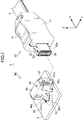
- FIG. 1 is a perspective view of an electrical connector device 1 using a cable connector 10 according to the present invention.
- the electrical connector device 1 includes a set of a cable connector 10 and a mating connector 90.
- the mating connector 90 may be a board-mounted connector connected to the board 3, but the mating connector 90 may also be a cable connection type, like the cable connector 10.
- the cable connector 10 can be fitted to and removed from the board connector 90.
- the fitting of the cable connector 10 and the board connector 90 can be locked using their shells.
- the tapered fitting portion 50a provided in the shell of the cable connector 10 is inserted into the substantially rectangular fitting hole 97 provided in the front surface of the board connector 90, Locked portions, for example, shells, that elastically protrude from the upper side and the lower side of the distal end portion 50a of the cable connector 10 into locked portions, for example, through holes 99, provided on the ceiling and bottom plate portions of the shell 98 of the board connector 90.
- the lock protrusion 35 protruding elastically from the hole 53 is fitted.
- the lock can be released using, for example, a lock claw operation unit 13 provided on the cable connector 10.
- the board connector 90 mainly includes an insulating housing 92, a terminal 96 held by the insulating housing 92 in a partially exposed state, and a conductive shell 98 that covers the outer peripheral surface of the insulating housing 92.
- a fitting hole 97 into which a part of the connector 10 can be fitted is provided on the front surface of the insulating housing 92.
- the fitting hole 97 is further provided with a fitting convex portion 97 a that fits the fitting concave portion 28 formed by the housing 20 of the connector 10.
- the fitting projections 97a are arranged with one end side 96a of the terminal 96 exposed.
- the other end 96 b of the terminal 96 is soldered to the substrate 3.
- a part 98a of the shell 98 is fixed at a predetermined position of the substrate 3, and the shell 98 is grounded to the ground.
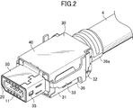
- FIG. 2 is a perspective view in which the hood 12 (see FIG. 1) is removed from the cable connector 10
- FIG. 3 is a perspective view in which the outer cover of the shell 30 and the electric cable 4 is removed from the state shown in FIG. .
- the cable connector 10 mainly includes a housing 20 made of an insulating member such as resin, a cable holder 60 that holds a plurality of twisted pair cables 5 included in the electric cable 4, a terminal support member 70 that supports the terminals 11, A conductive shell 30 covering the outer peripheral surfaces of the housing 20 and the cable holder 60 and an insulating hood 12 (see FIG. 1) covering the outside of the shell 30 are further included. Since the cable holder 60 and the terminal support member 70 are used in a state of being incorporated in the housing 20 and constitute a part of the housing together with the housing 20, it is understood that they are housings in a broad sense. It's okay. Here, a total of four twisted pair cables 5 are provided.
- the shell 30 includes a main body shell 31, a plate-like shell 40, and a cylindrical shell 50.
- the plate-like shell 40 and the main body shell 31 mainly cover side outer peripheral surfaces of the housing main body 29 and the like.
- the plate-like shell 40 mainly covers the outer peripheral surface of the side part of the housing main body 29 and the like that are not covered by the main body shell 31.
- the cylindrical shell 50 mainly covers the outer peripheral surface of the side portion of the insertion portion 25 having a slightly small diameter that protrudes from the housing body 29.
- the main body shell 31 is formed by punching a single metal plate and bending it.
- the cross section has a substantially U-shape as a whole, and mainly includes a base portion 36, an elastic piece 33 extending forward of the base portion 36, and a caulking portion 36 a of the electric cable 4 extending rearward of the base portion 36.
- the base portion 36 and the elastic piece 33 are elastically connected to each other at the rear end portion of the base portion 36 via a support portion 32 formed as a folded portion having a substantially U shape in cross section.
- the elastic piece 33 has a free end on the mating side with the board connector 90, and a lock projection 35 used for locking with the board connector 90 is provided at the free end.
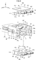
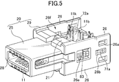
- FIG. 4 shows a state in which the cable holder 60 (60a, 60b) is removed from the state of FIG. 3 in a rear perspective view together with the removed cable holders 60a, 60b, and FIG.
- the state which removed the cable holding bodies 60a and 60b from the state is shown with a front perspective view.
- the housing 20 includes a housing main body 29 and a portion 25 to be inserted that protrudes from the housing main body 29 to the side where the board connector 90 (see FIG. 1) is fitted.
- the inserted portion 25 is a portion to be inserted into the fitting hole 97 (see FIG. 1) of the board connector 90, and a fitting recess 28 into which the fitting protrusion 97a of the board connector 90 is inserted is provided inside. Is formed.
- the housing main body 29 includes a thick base portion 21 and two opposing plate-like side walls 26 extending rearward of the base portion 21, that is, opposite to the inserted portion 25. In a space 26f formed between the side walls 26, a pair of terminal support members 70a and 70b and a pair of cable holders 60a and 60b are installed.
- the housing body 29 has a substantially rectangular shape when complemented by the terminal support members 70 a and 70 b and the cable holding body 60.
- the cable holders 60a and 60b forming a pair have the same size and shape.
- the paired terminal support members 70a and 70b preferably have the same size and shape.
- Each of the cable holders 60 a and 60 b includes a substantially rectangular main body 67 and a cantilevered arm portion 61 extending from the main body 67 along the attachment direction “ ⁇ ” of the cable holder 60 to the housing 20.
- the arm portion 61 is connected to the main body 67 on one end side opposite to the free end.
- the arm portion 61 is provided so as to be elastically displaceable in the thickness direction.
- the main body 67 is provided with a plurality of through holes 63 through which the cable 5 is inserted along the length direction “ ⁇ ” of the cable 5.
- One end side of the twisted pair cable 5 is attached to the cable holding body 60 using these through holes 63.
- the inner diameter of the through hole 63 is set to be substantially the same as or slightly smaller than the outer diameter of the cable 5. Thereby, the outer peripheral surface of the cable 5 and the inner peripheral surface of the through hole 63 are caught, and the cable 5 can be prevented from being unintentionally detached from the through hole 63.
- the left and right side surfaces 67c and 67d of the main body 67 are provided with locking protrusions 62 that are locked in locking holes 26a (see FIGS. 3 to 5) provided in the side wall 26 of the housing 20. Further, in the vicinity of the free end of the arm portion 61, a locking projection that is locked to a locking projection 83 (see FIGS. 4 to 6) provided on the standing portions 75a and 75b of the terminal support members 70a and 70b. 61a is provided.
- the cable holding body 60 can be locked to the housing 20 using these locking means.
- the locking protrusions 62 of the cable holding bodies 60a and 60b and the locking holes 26a on the housing 20 side are locked, and the locking protrusions 61a of the cable holding bodies 60a and 60b and the terminals.
- the cable holding body 60 is locked to the housing 20 and the terminal support member 70 at different locations, respectively.
- the fixing between the member 70 and the cable holder 60 can be strengthened.
- Locking protrusions 81 that are locked using grooves provided on the inner surface of the side wall 26 of the housing body 29 are provided on the left and right side surfaces of the standing portions 75a and 75b.
- the bottom surface 67b of the main body 67 is provided with an insertion hole 64 into which an upright portion (11b) projected from the main surfaces 72 (72a, 72b) of the terminal support members 70a, 70b is inserted later.
- the insertion hole 64 communicates with a through hole 63 through which the twisted pair cable 5 is inserted, and an insulating coating for the twisted pair cable 5 inserted through the through hole 63 when the cable holders 60 a and 60 b are attached to the housing 20.
- 5a (refer FIG. 4) can be cut
- the inner core wire 5b (see FIG. 4) is sandwiched between the grooves, and the cable 5 and the terminal 11 are electrically connected.
- the bottom surface 67b of the main body 67 is provided with protrusions 66a and 66b that fit into the notches 76a and 76b provided in the terminal support members 70a and 70b.
- the protrusions 66a and 66b are attached to the surface of the cable holders 60a and 60b attached to the housing 20, that is, the bottom surface 67b, and the mounting direction “ ⁇ ” of the cable holders 60a and 60b with respect to the housing 20, Stands in the same direction.
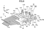
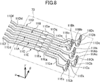
- FIG. 6 is a perspective view of the terminal support members 70a and 70b together with the terminals 11, and FIG. 7 is a side view of the configuration shown in FIG. Further, FIG. 8 is a perspective view showing an arrangement state of the terminals 11 supported by the terminal support member 70, and FIG. 9 is a side view of the configuration shown in FIG.
- the cable connector 10 is provided with, for example, five terminals 11A to 11E so as to be compatible with a plurality of categories 6a based on IEEE802.3.
- These terminals 11A to 11E include two signal terminal pairs (11B, 11D) (11C, 11E) that are spaced apart from each other in the inter-terminal direction “ ⁇ ”, and these in the inter-terminal direction “ ⁇ ”. Between one pair of signal terminals (11B, 11D) and the other pair of signal terminals (11C, 11E) of the two pairs of signal terminals (11B, 11D) (11C, 11E) And a ground terminal 11A.
- one pair of signal terminals (11B, 11D) includes a signal terminal 11B disposed on the side closer to the ground terminal 11A in the inter-terminal direction “ ⁇ ” and a side far from the ground terminal 11A in the inter-terminal direction “ ⁇ ”. Including a signal terminal 11D.
- the other pair of signal terminals (11C, 11E) is a signal terminal 11C arranged on the side close to the ground terminal 11A in the inter-terminal direction “ ⁇ ” and a side far from the ground terminal 11A in the inter-terminal direction “ ⁇ ”. Including a signal terminal 11E.
- Each of the terminals 11A to 11E is formed by punching and bending a piece of metal, and is press-fitted into the housing 20 and a contact portion 11d provided on the distal end side 11f to be brought into contact with a mating terminal (terminal “96” in FIG. 1). , A locking portion 11a for locking, a support portion 11g supported by the terminal support member 70, and cable connection portions (11b, 11c) to which the cable 5 (see FIG. 4 and the like) is connected.
- the contact portion 11d is a portion to be brought into contact with the mating terminal and includes, for example, a contact provided near the tip 11f of the terminal.
- the contact portion 11d is not limited to the contact point, and widely includes a portion to be brought into contact with the mating terminal.
- the support portion 11g is a portion supported by the terminal support member 70 and is integrally formed with the terminal support member 70, but may be of a type that is press-fitted into the terminal support member 70.
- the support portion 11g may be formed as a curved portion having a substantially “S” shape.
- the support portion 11g can be supported by the standing portions 75a and 75b of the terminal support member 70.
- the support portion 11g and the contact portion 11d correspond to the length direction “ ⁇ ” of the terminals 11A to 11E orthogonal to the inter-terminal direction “ ⁇ ” between the terminals 11A to 11E (corresponding to the length direction “ ⁇ ” of the cable 5). And the same height in the height direction “ ⁇ ” (corresponding to the mounting direction “ ⁇ ” described above) perpendicular to both the inter-terminal direction “ ⁇ ” and the length direction “ ⁇ ”. It is preferable that it is positioned in this position.
- the standing portions 75a and 75b are also positioned at the same height in the height direction “ ⁇ ” between the terminals 11A to 11E, and in the height direction. It is preferable to have the same length in “ ⁇ ”. Thereby, crosstalk can be prevented more effectively.
- this apparatus can be used not only as a standard product of category 6 of IEEE but also as a standard product of category 5, for example.
- the cable connection part includes a flat part 11c and an upright part 11b.
- the flat portion 11c may have, for example, a substantially triangular shape when viewed from above, and the main surface 72 (72a, 72a, 70b) of the terminal support member 70 (70a, 70b) having the inter-terminal direction “ ⁇ ” and the length direction “ ⁇ ”. 72b), more specifically, a part of the main surface of the terminal support member 70 (70a, 70b) supporting the vicinity of the flat portion 11c.
- a flat portion 11c is provided for each of the terminals 11A to 11E, the ground terminal 11A includes a ground flat portion 11Ac, and the signal terminals 11B to 11E include signal flat portions 11Bc to 11Ec, respectively.
- the raised portion 11 b is raised from the main surface 72 of the terminal support member 70 toward the cable connection side in the height direction “ ⁇ ” in a state of being exposed from the terminal support member 70.
- inter-terminal distance conversion sections 11Ae to 11Ee may be provided between the rising portions 11Ab to 11Eb and the support sections 11Ag to 11Eg (FIG. 8).
- the distance between the upright portions 11Ab to 11Eb can be made larger than the distance between the tips 11Af to 11Ef in the inter-terminal direction “ ⁇ ”. It is possible to facilitate the pressure welding work.
- These inter-terminal distance converters 11Ae to 11Ee also play an important role in reducing crosstalk.
- the terminals 11A to 11E are supported in a cantilever manner by the terminal support members 70a and 70b.
- the terminals 11A to 11E may be supported by the terminal support member by being integrated in the respective support portions 11Ag to Eg at the time of manufacture, or may be supported by the terminal support members 70a and 70b from the rear using press-fitting or the like. Alternatively, it may be supported by being incorporated from above. In this example, description will be made on the assumption that it is integrally formed. Even after incorporation, a part of the terminal 11 is exposed to the outside.
- the front of the terminals 11A to 11E that is, the vicinity of the tips 11Af to 11Ef of the terminals 11A to 11E extended to the base 21 side of the housing 20, or the rear of the terminals 11, that is, the twisted pair cable 5 is pressed.
- the upper portions 11Ab to Eb and the like are exposed to the outside.
- the ends Af to 11Ef of the terminals 11A to 11E can be elastically displaced along the height direction “ ⁇ ”.
- Terminal support members 70a and 70b have plate-like main bodies 77a and 77b that form main surfaces 72a and 72b, respectively.
- Standing portions 75a and 75b are provided on the upper surfaces of the main bodies 77a and 77b
- lock projections 71a projecting outward are provided on the left and right side surfaces of the main bodies 77a and 77b
- the rear edges of the main bodies 77a and 77b are directed inward.
- Cutout U-shaped cutouts 76a and 76b are provided, respectively.
- the paired terminal support members 70a and 70b are abutted on the flat bottom surfaces 78a and 78b in the height direction “ ⁇ ”. These abutting surfaces are flat surfaces. By using such a surface, the abutting surfaces can be abutted in a more stable state.
- the terminal 11 supported by the terminal support members 70a and 70b has an object to be contacted, for example, a board connector 90 (see FIG. 1) between the contact points 11d.
- a gap “G” (see FIG. 7) into which the fitting convex portion 97 a is inserted is formed.
- the gap “G” is formed along the height direction “ ⁇ ” along the abutting direction of the terminal support members 70 forming a pair.
- the terminal support members 70a and 70b are extended from the standing portions 75a and 75b so that a part of the core wire exposed from the tip (end) of the cable 5 held by the cable holder 60 is not short-circuited with the adjacent terminal. It is preferable to provide the extended portion 74.
- the extending portion 74 extends from the standing portions 75a and 75b toward the rising portion 11b in the upper surfaces of the terminal support members 70a and 77b, and covers at least a part of the wiring portion 11g of the terminal 11. .
- a taper 74 a is formed at the tip of the extended portion 74 in order to prevent a collision with the cable holding portion 60.
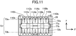
- FIGS. 10 and 11 are plan views of the configuration shown in FIG. 5, and FIG. 11 is a rear view of the configuration shown in FIG.
- At least a part of the ground upright portion 11Ab of the ground terminal 11A is in at least one plane orthogonal to the height direction “ ⁇ ” and extending in parallel to the main surfaces 72a and 72b of the terminal support member 70, for example, FIG. 9 and FIG. 11, in the surface 73 (73a, 73b) shown in FIG. 10, as shown in FIG. 10, the first position located between the signal rising portion 11Bb and the signal rising portion 11Cb in the inter-terminal direction “ ⁇ ”. It is located within the range of the intersection “a” between the virtual portion “a1” and the second virtual portion “a2” located between the signal rising portion 11Bb and the signal rising portion 11Cb in the length direction “ ⁇ ”. .
- the ground rising portions 11Ab and the signal rising portions 11Bb to 11Eb are opposed to each other in the same height direction, and as a result, one signal terminal pair (11B, 11D), noise (crosstalk) generated between the signal rising portions 11Bb and 11Db included in the signal rising portion 11Cb and 11Eb included in the other signal terminal pair (11C and 11E) It can be effectively reduced or eliminated by the ground upright portion 11Ab provided therebetween. That is, between the signal rise 11Bb and the signal rise 11Cb, between the signal rise 11Bb and the signal rise 11Eb, between the signal rise 11Db and the signal rise 11Cb, and between the signal rise 11Db and the signal rise 11Eb.
- the electric lines of force generated between the two can be efficiently coupled to the ground upright portion 11Ab, and crosstalk can be effectively reduced or eliminated.
- “all” surfaces in which “all portions” of the ground upright portion 11Ab in the height direction “ ⁇ ” are orthogonal to the height direction “ ⁇ ” and extend parallel to the main surfaces 72a and 72b It does not have to be located within the intersection zone “a”.
- “all parts” of the ground upright portion 11Ab are positioned within the range of the intersection area “a” in at least one plane. It suffices that at least a part of the ground upright portion 11Ab in the height direction “ ⁇ ” is positioned within the range of the intersection area “a” in at least one plane. This is because even in such a case, the electric lines of force can be efficiently coupled to the ground upright portion 11Ab.
- the ground rising portion 11 ⁇ / b> Ab is a signal included in the center of the signal rising portion 11 ⁇ / b> Bb included in one signal terminal pair (11 ⁇ / b> B, 11 ⁇ / b> D) and the other signal terminal pair (11 ⁇ / b> C, 11 ⁇ / b> E). It is preferable to arrange on the straight line “k” connecting the center of the upright portion 11Cb, in other words, on the straight line “k” forming the shortest distance between the center of the signal upright portion 11Bb and the center of the signal upright portion 11Cb. Since noise is most likely to occur at such a position, the noise can be more effectively reduced by arranging the ground upright portion 11Ab at this position.
- the ground rising portion 11Ab is not limited to this position, and may be positioned within the range of the above-described intersection area “a”. This is because the noise extends three-dimensionally not only on the straight line “k” but also in the space existing between the pair of signal terminals.
- the straight line “k” is expressed as a line that forms the shortest distance between the center of the signal rising portion 11Bb and the center of the signal rising portion 11Cb.
- the line “k” is not limited to this, and for example, one signal terminal pair (11B, 11D) and the signal rising portion (11Bb, 11Db) included in the other signal terminal pair (11C, 11E) and the signal rising portion (11Cb, 11Eb) included in the other signal terminal pair can be regarded as a straight line. is there.
- either one of the signal rising portion 11Bb and the signal rising portion 11Cb is placed closer to the contact side with the mating terminal than the ground rising portion 11Ab or farther from the contact side with the mating terminal.
- the other may be positioned on the side farther from the contact side with the mating terminal than the ground upright portion 11Ab or near the contact side with the mating terminal. For example, in the example shown in FIG.
- the signal rising portion 11Bb is positioned closer to the contact side with the counterpart terminal than the ground rising portion 11Ab in the longitudinal direction “ ⁇ ”,
- the raised portion 11Cb is positioned on the side farther from the contact side with the mating terminal than the ground raised portion 11Ab.
- the signal rising portion 11Bb and the signal rising portion 11Cb may be positioned at the same position in the length direction “ ⁇ ”.
- the signal rising portion 11Bb and the signal rising portion 11Cb may be positioned at the same position as the ground rising portion 11Ab.
- either one of the signal rising portion 11Db and the signal rising portion 11Eb is closer to the contact side with the mating terminal than the ground rising portion 11Ab or farther from the contact side with the mating terminal.
- the other may be positioned farther from the contact side with the mating terminal than the ground upright portion 11Ab or closer to the contact side with the mating terminal.
- the signal rising portion 11Db and the signal rising portion 11Eb may be positioned at the same position in the length direction “ ⁇ ”.
- the signal rising portion 11Db and the signal rising portion 11Eb are positioned at the same position as the ground rising portion 11Ab in the length direction “ ⁇ ”.
- the ground rising portion 11Ab, the signal rising portion 11Bb, and the signal rising portion 11Db are isosceles with the signal rising portion 11Bb as an apex. It is preferable to form a triangle, and the ground rising portion 11Ab, the signal rising portion 11Cb, and the signal rising portion 11Eb preferably form an isosceles triangle having the signal rising portion 11Cb as a vertex. Further, in this case, the signal rising portion 11Bb and the signal rising portion 11Cb forming the apex are positioned on the opposite side to the ground rising portion 11Ab in the length direction “ ⁇ ” as shown in FIG. Is preferred.
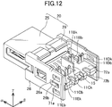
- FIG. 12 to FIG. 14 show modifications.
- 12 is a view corresponding to FIG. 5 and the like, and shows a state in which the cable holders 60a and 60b are removed from the state of FIG. 3 in a rear perspective view
- FIG. 13 shows the configuration shown in FIG.
- FIG. 14 is a rear view of the configuration shown in FIG.
- the ground upright portion 11Ab substantially extends in the inter-terminal direction “ ⁇ ”, but may extend in the length direction “ ⁇ ” as shown in FIG. . Even in the case of extending in the length direction “ ⁇ ”, at least a part of the ground upright portion 15 is orthogonal to the height direction “ ⁇ ” and supports the terminal, like the connector described with reference to FIG.
- FIG. 15 shows another modification.
- the signal rising portion 11Bb and the signal rising portion 11Cb are positioned at the same position in the length direction “ ⁇ ”.
- the second virtual portion “a2” is linear.
- the intersection area “a” where the first virtual part “a1” and the second virtual part (virtual line) intersect is also linear. Even in such a case, the noise can be reduced by positioning the ground rising portion 15A within the range of the crossing area (line area).
- the ground rising portion 15A is preferably extended beyond the second virtual portion “a2” in the length direction “ ⁇ ”, for example, to the side far from the contact side with the mating terminal as shown in the figure.
- FIG. 16 shows a conventional general connector configuration, that is, a configuration without a raised portion as disclosed in Patent Document 1 and the like
- a configuration shown in FIG. 6 is a graph showing the simulation of the insertion loss obtained by each of the configurations according to the modified example 1 shown in FIG. 6 and comparing these simulation results with the standard value of the insertion loss in category 6a based on IEEE802.3.
- the horizontal axis represents frequency (GHz), and the vertical axis represents insertion loss (dB).
- ANSYS HFSS manufactured by ANSYS was used.
- the conventional general connector configuration also clears the standard value, but according to this configuration, it is clear that the value is further improved.
- a cable connector having an upright portion for connecting a cable which has a good transmission characteristic and can easily perform a wiring work.
- the present invention is not limited to the above-described embodiment, and various other modifications are possible.
- the contact used for four typical twisted pair cables has been described as an example.
- the number of core wires used for the connector differs depending on the LAN cable standard.
- a connector used for a twisted pair cable other than the four sets can be easily developed.
- the present invention may be configured in other and different embodiments, and numerous details may be modified in various obvious respects without departing from the spirit and scope of the invention. it can. Accordingly, the drawings and description are merely examples and are not intended to be limiting.
Landscapes
- Details Of Connecting Devices For Male And Female Coupling (AREA)
- Connections By Means Of Piercing Elements, Nuts, Or Screws (AREA)
Priority Applications (3)
| Application Number | Priority Date | Filing Date | Title |
|---|---|---|---|
| US16/606,029 US10734766B2 (en) | 2017-04-20 | 2018-03-27 | Cable connector including rising portions for cable connection and electrical connector apparatus using the same |
| CN201880013122.0A CN110326173B (zh) | 2017-04-20 | 2018-03-27 | 具有线缆连接用的立起部的线缆连接器、以及使用该线缆连接器的电连接器装置 |
| EP18787983.8A EP3614505A4 (en) | 2017-04-20 | 2018-03-27 | CABLE CONNECTOR WITH INCREASING CABLE CONNECTOR PART AND ELECTRICAL CONNECTOR DEVICE WITH IT |
Applications Claiming Priority (2)
| Application Number | Priority Date | Filing Date | Title |
|---|---|---|---|
| JP2017-083832 | 2017-04-20 | ||
| JP2017083832A JP6946042B2 (ja) | 2017-04-20 | 2017-04-20 | ケーブル接続用の立上部を有したケーブルコネクタと、これを用いた電気コネクタ装置 |
Publications (1)
| Publication Number | Publication Date |
|---|---|
| WO2018193796A1 true WO2018193796A1 (ja) | 2018-10-25 |
Family
ID=63855734
Family Applications (1)
| Application Number | Title | Priority Date | Filing Date |
|---|---|---|---|
| PCT/JP2018/012353 WO2018193796A1 (ja) | 2017-04-20 | 2018-03-27 | ケーブル接続用の立上部を有したケーブルコネクタと、これを用いた電気コネクタ装置 |
Country Status (5)
| Country | Link |
|---|---|
| US (1) | US10734766B2 (zh) |
| EP (1) | EP3614505A4 (zh) |
| JP (1) | JP6946042B2 (zh) |
| CN (1) | CN110326173B (zh) |
| WO (1) | WO2018193796A1 (zh) |
Families Citing this family (11)
| Publication number | Priority date | Publication date | Assignee | Title |
|---|---|---|---|---|
| USD852142S1 (en) * | 2015-12-03 | 2019-06-25 | Hirose Electric Co., Ltd. | Electrical connector |
| US10965054B2 (en) * | 2016-07-20 | 2021-03-30 | Hirose Electric Co., Ltd. | Cable connector having cable holders |
| TWI828624B (zh) | 2017-06-13 | 2024-01-11 | 美商山姆科技公司 | 電連接器系統及其使用方法 |
| USD964291S1 (en) | 2017-07-21 | 2022-09-20 | Samtec, Inc. | Electrical connector |
| TW202306256A (zh) | 2017-07-21 | 2023-02-01 | 美商山姆科技公司 | 具有鎖扣的電連接器以及包含電連接器的系統 |
| TWI813591B (zh) * | 2017-10-24 | 2023-09-01 | 美商山姆科技公司 | 直角電連接器、用於直角連接器的接地屏蔽和電接點、組裝有角度的電連接器之方法、導線架組件、形成用於有角度的電連接器的電接點之方法 |
| USD896183S1 (en) | 2018-01-08 | 2020-09-15 | Samtec, Inc. | Electrical cable connector |
| USD999171S1 (en) * | 2021-01-20 | 2023-09-19 | Hirose Electric Co., Ltd. | Electrical connector |
| CN115021009A (zh) | 2021-03-05 | 2022-09-06 | 广濑电机株式会社 | 线缆保持部件以及具有线缆保持部件的线缆连接器装置 |
| JP7274007B2 (ja) * | 2021-03-05 | 2023-05-15 | ヒロセ電機株式会社 | ケーブル保持部材、及びケーブル保持部材を有するケーブルコネクタ装置 |
| JP1699971S (zh) * | 2021-03-09 | 2021-11-15 |
Citations (4)
| Publication number | Priority date | Publication date | Assignee | Title |
|---|---|---|---|---|
| JPH09180799A (ja) * | 1995-12-25 | 1997-07-11 | Matsushita Electric Works Ltd | コネクタ |
| JP2004079377A (ja) * | 2002-08-20 | 2004-03-11 | Auto Network Gijutsu Kenkyusho:Kk | 多芯型ケーブルの端末接続構造 |
| JP2007012588A (ja) * | 2005-05-31 | 2007-01-18 | Fujitsu Component Ltd | 平衡伝送用ケーブルコネクタ |
| JP4623584B2 (ja) | 2005-12-28 | 2011-02-02 | 日本航空電子工業株式会社 | コネクタ |
Family Cites Families (15)
| Publication number | Priority date | Publication date | Assignee | Title |
|---|---|---|---|---|
| CA1298369C (en) * | 1987-11-06 | 1992-03-31 | George Debortoli | Insulation displacement members and electrical connectors |
| JPH0785909A (ja) * | 1993-09-17 | 1995-03-31 | Kel Corp | 圧接コネクタ |
| JP2972067B2 (ja) * | 1993-09-21 | 1999-11-08 | 富士通株式会社 | コネクタ |
| AU716436B2 (en) | 1995-12-25 | 2000-02-24 | Matsushita Electric Works Ltd. | Connector |
| US6077122A (en) * | 1997-10-30 | 2000-06-20 | Thomas & Bett International, Inc. | Electrical connector having an improved connector shield and a multi-purpose strain relief |
| US20030003793A1 (en) * | 2001-07-02 | 2003-01-02 | Che-Chia Chang | Electrical connector with distribution contacts |
| JP2003257558A (ja) * | 2002-02-27 | 2003-09-12 | Honda Tsushin Kogyo Co Ltd | 高速伝送用コネクタ |
| US7018230B2 (en) * | 2004-03-12 | 2006-03-28 | Channell Commercial Corporation | Electrical connector |
| US20070082539A1 (en) * | 2005-10-12 | 2007-04-12 | Slobadan Pavlovic | Insulation displacement connection for securing an insulated conductor |
| US8951050B2 (en) * | 2011-02-23 | 2015-02-10 | Japan Aviation Electronics Industry, Limited | Differential signal connector capable of reducing skew between a differential signal pair |
| JP5811460B2 (ja) * | 2012-02-15 | 2015-11-11 | ホシデン株式会社 | コネクタ |
| CN103457063A (zh) * | 2012-05-30 | 2013-12-18 | 凡甲电子(苏州)有限公司 | 线缆连接器组件 |
| WO2015164538A1 (en) * | 2014-04-23 | 2015-10-29 | Tyco Electronics Corporation | Electrical connector with shield cap and shielded terminals |
| US9496626B2 (en) * | 2015-01-27 | 2016-11-15 | The Patent Store Llc | Insulation displacement connector with joined blade connectors |
| CN106532279B (zh) * | 2016-12-31 | 2024-02-13 | 上海天诚通信技术股份有限公司 | 全自动打线式信息模块 |
-
2017
- 2017-04-20 JP JP2017083832A patent/JP6946042B2/ja active Active
-
2018
- 2018-03-27 CN CN201880013122.0A patent/CN110326173B/zh active Active
- 2018-03-27 EP EP18787983.8A patent/EP3614505A4/en active Pending
- 2018-03-27 WO PCT/JP2018/012353 patent/WO2018193796A1/ja unknown
- 2018-03-27 US US16/606,029 patent/US10734766B2/en active Active
Patent Citations (4)
| Publication number | Priority date | Publication date | Assignee | Title |
|---|---|---|---|---|
| JPH09180799A (ja) * | 1995-12-25 | 1997-07-11 | Matsushita Electric Works Ltd | コネクタ |
| JP2004079377A (ja) * | 2002-08-20 | 2004-03-11 | Auto Network Gijutsu Kenkyusho:Kk | 多芯型ケーブルの端末接続構造 |
| JP2007012588A (ja) * | 2005-05-31 | 2007-01-18 | Fujitsu Component Ltd | 平衡伝送用ケーブルコネクタ |
| JP4623584B2 (ja) | 2005-12-28 | 2011-02-02 | 日本航空電子工業株式会社 | コネクタ |
Also Published As
| Publication number | Publication date |
|---|---|
| US20200044395A1 (en) | 2020-02-06 |
| EP3614505A1 (en) | 2020-02-26 |
| EP3614505A4 (en) | 2020-12-30 |
| CN110326173A (zh) | 2019-10-11 |
| US10734766B2 (en) | 2020-08-04 |
| JP2018181769A (ja) | 2018-11-15 |
| CN110326173B (zh) | 2021-10-08 |
| JP6946042B2 (ja) | 2021-10-06 |
Similar Documents
| Publication | Publication Date | Title |
|---|---|---|
| WO2018193796A1 (ja) | ケーブル接続用の立上部を有したケーブルコネクタと、これを用いた電気コネクタ装置 | |
| JP7051634B2 (ja) | コネクタ | |
| JP2020057499A (ja) | 電気コネクタ、および電気コネクタセット | |
| US6190215B1 (en) | Stamped power contact | |
| US9972950B2 (en) | Shield case, and connector having the same | |
| WO2018016388A1 (ja) | 端子支持体を有する電気コネクタ | |
| KR101738337B1 (ko) | 커넥터 | |
| WO2018016389A1 (ja) | ケーブル保持体を有するケーブルコネクタ | |
| US20090275245A1 (en) | Electrical connector with improved contacts | |
| JPH0737635A (ja) | 電気接続端子 | |
| US20120164862A1 (en) | Electrical connector having improved contact member | |
| KR101680180B1 (ko) | 커넥터 | |
| WO2016035841A1 (ja) | 通信用コネクタ | |
| JP2010157368A (ja) | 電気コネクタ | |
| US7775837B2 (en) | Electrical connector with improved clip member | |
| US20080076303A1 (en) | Electrical connector | |
| US20080293286A1 (en) | Cable connector and circuit board connector to be connected to the same | |
| JP6599149B2 (ja) | コネクタ | |
| JP2010157367A (ja) | 電気コネクタ | |
| JP2022035188A (ja) | コネクタ | |
| JP7274007B2 (ja) | ケーブル保持部材、及びケーブル保持部材を有するケーブルコネクタ装置 | |
| US11909138B2 (en) | Terminal assembly including flat surface formed and aligned for achieving flat contact with mating tab | |
| JP6406705B2 (ja) | コンタクト、リセプタクル及びコネクタ | |
| KR101520927B1 (ko) | 터미널 | |
| JP2016066406A (ja) | コネクタ |
Legal Events
| Date | Code | Title | Description |
|---|---|---|---|
| 121 | Ep: the epo has been informed by wipo that ep was designated in this application |
Ref document number: 18787983 Country of ref document: EP Kind code of ref document: A1 |
|
| NENP | Non-entry into the national phase |
Ref country code: DE |
|
| ENP | Entry into the national phase |
Ref document number: 2018787983 Country of ref document: EP Effective date: 20191120 |