WO2018189930A1 - 布団乾燥機および吹出ユニット - Google Patents
布団乾燥機および吹出ユニット Download PDFInfo
- Publication number
- WO2018189930A1 WO2018189930A1 PCT/JP2017/031311 JP2017031311W WO2018189930A1 WO 2018189930 A1 WO2018189930 A1 WO 2018189930A1 JP 2017031311 W JP2017031311 W JP 2017031311W WO 2018189930 A1 WO2018189930 A1 WO 2018189930A1
- Authority
- WO
- WIPO (PCT)
- Prior art keywords
- unit
- cover
- blowing unit
- cylindrical handle
- flow path
- Prior art date
- Legal status (The legal status is an assumption and is not a legal conclusion. Google has not performed a legal analysis and makes no representation as to the accuracy of the status listed.)
- Ceased
Links
Images









Classifications
-
- D—TEXTILES; PAPER
- D06—TREATMENT OF TEXTILES OR THE LIKE; LAUNDERING; FLEXIBLE MATERIALS NOT OTHERWISE PROVIDED FOR
- D06F—LAUNDERING, DRYING, IRONING, PRESSING OR FOLDING TEXTILE ARTICLES
- D06F58/00—Domestic laundry dryers
Definitions
- a typical futon dryer includes a main unit, a hose, and a drying mat (air bag) (Japanese Patent Laid-Open No. 08-010499).
- the main unit supplies hot air into the drying mat through a hose.
- the drying mat By expanding the drying mat between the mattress and the comforter, the mattress and the comforter can be efficiently dried.
- Such a futon dryer may not obtain a sufficient drying effect in the following cases.
- the hot air supply capacity of the futon dryer is weak
- the weight of the comforter is heavier than expected (than the warm air output value set by the user)
- the drying mat is folded and placed
- the mat may not be correctly placed between the futons.
- the futon dryer as described above uses heat conduction through the drying mat as one of the main drying means.
- the dry mat is easy to adhere to a mattress located below the dry mat.
- the comforter is located above the drying mat and is flexible and easily deformed.
- the dry mat is difficult to adhere to the comforter, and a gap is easily formed between them. Heat conduction to the comforter through the drying mat is often difficult, and a sufficient drying effect cannot be obtained, or the electricity bill becomes high due to long-time drying.
- the futon dryer disclosed in this publication includes a main body unit and a blowing unit (drying unit) connected to the main body unit via a hose.
- the blowout unit has a box shape (substantially rectangular parallelepiped shape), and the blowout unit is provided with a plurality of blowout ports for blowing warm air to the outside.
- the futon is dried with the blowout unit placed between the mattress and the comforter.
- the drying mat type futon dryer may be restricted depending on the shape and size of the drying mat, the installation condition of the drying mat, etc., but according to the futon dryer as described above which does not use the drying mat, The futon can be dried without such restrictions.
- a blowing unit is placed between the comforter and the mattress.
- the blowing unit blows warm air toward a space (gap) formed between the comforter and the mattress. If a space with sufficient space is not formed between the comforter and the mattress, the warm air blown from the blowout unit does not reach every corner of the futon, and as a result, it becomes difficult to obtain a sufficient drying effect.
- a space space with sufficient space is not formed between the comforter and the mattress, the warm air blown from the blowout unit does not reach every corner of the futon, and as a result, it becomes difficult to obtain a sufficient drying effect.
- the blowout unit (drying unit) disclosed in Japanese Patent Application Laid-Open No. 2016-064126 has a flat box shape. Even if the flat box shape of the blowing unit is positively used, it is not easy to form a space having a sufficient area around the blowing unit. If you are accustomed to a futon dryer, after placing the blowout unit between the comforter and the mattress, pull the comforter partly to form the space above (the comforter's bulge) between the comforters You might think of it, but there is a possibility that such a space will become smaller due to the weight of the comforter.
- the futon dryer As a countermeasure, for example, it is conceivable to configure the futon dryer so as to have a size and blowing capacity larger than those originally required for drying the futon. However, enlarging the blowout unit having a flat box shape leads to an increase in the size of the entire apparatus. It is conceivable to incorporate a high-performance air blower or heater, but this increases the product cost, increases the noise, and increases the cost of electricity.
- the present specification discloses a blowout unit having a configuration capable of forming a space having a sufficient width between a comforter and a mattress, and a futon dryer provided with such a blowout unit. Objective.
- the blowout unit is a blowout unit that is provided in the futon dryer and blows out warm air, and has a cylindrical handle having a cylindrical shape, and the tip opening at a position away from the tip opening of the cylindrical handle.
- a cover portion that is provided so as to cover and has a generally umbrella-like shape as a whole together with the cylindrical handle portion, and in the state in which the cover portion and the cylindrical handle portion are inserted between the mattress and the comforter The comforter is supported by the cover part and the cylindrical handle part, and the warm air blown from the tip opening of the cylindrical handle part is turned in contact with the inner surface of the cover part, and the cover part and The tubular handle is blown out toward a space formed between the mattress and the comforter and around the cover.
- the inner surface of the cover portion is formed such that warm air blown from the tip opening of the cylindrical handle portion and turned in contact with the inner surface is turned at an angle of 45 ° or more. May be.
- the blow-out unit extends in the circumferential direction so as to surround the cylindrical handle portion, and is disposed so as to face the cover portion with a space therebetween, and a flow path of warm air between the cover portion and the cover portion. And the total sum of the cross-sectional areas of the portions of the flow channel at a predetermined diameter centered on the central axis of the cover portion is from the inner side to the outer side in the radial direction. It may grow gradually.
- the change rate may be greater than 0 and a substantially constant value.
- the length may be configured to gradually decrease from the inner side to the outer side in the radial direction.
- a plurality of the flow paths that are divided by a partition wall may be formed between the cover part and the bowl-shaped part.
- the portion of each of the plurality of the channels that forms the plurality of flow paths has a curved shape that bulges toward the inside of the flow path
- the part which forms each of the said some flow path of the said cover part may have the curved surface shape which recedes in concave shape from the inner side of the said flow path.
- the futon dryer includes a main unit that generates warm air, a hose connected to the main unit, and the blowout unit.
- the main unit has an installation part on the upper part of the main unit where the blowing unit can be detachably installed, and the hose and the blowing unit are installed in the installation part. Hot air may be blown out through the blowing unit.
- the main body unit has a shielding portion that surrounds a part of the periphery of the blowout unit installed in the installation portion, and blows out from the blowout unit toward the left and right directions and the rear of the main body unit.
- the heated warm air may be turned in contact with the shielding portion and blown out to the front side of the main unit.
- a space having a sufficient area can be formed between the comforter and the mattress by utilizing the umbrella shape of the blowing unit.
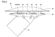
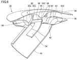
- FIG. 3 is a side view showing a blowing unit 30 in the first embodiment.
- FIG. 3 is a cross-sectional view showing a blowing unit 30 in the first embodiment.
- FIG. 3 is a cross-sectional perspective view showing a blowing unit 30 in the first embodiment.
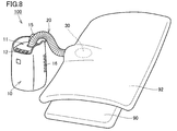
- FIG. 5 is a cross-sectional perspective view taken along the line VII-VII in FIG. 4. It is a perspective view which shows the use condition of the futon dryer 100 in Embodiment 1.
- FIG. It is a figure which shows a mode that the blowing unit 30 in Embodiment 1 is arrange
- FIG. FIG. 8 is a cross-sectional perspective view corresponding to FIG. 7, showing a state in which hot air is flowing inside the blowing unit 30 in the first embodiment.
- FIG. 6 is a cross-sectional view corresponding to FIG. 5, showing a state in which hot air is flowing inside the blowing unit 30 in the first embodiment.
- FIG. 5 is a perspective view corresponding to FIG.
- FIG. 4 showing a state in which hot air is flowing inside the blowing unit 30 in the first embodiment.
- It is a side view which shows a mode that the warm air is flowing through the inside of the blowing unit 30 in the 1st modification of Embodiment 1.
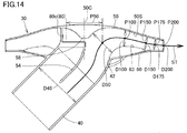
- FIG. It is sectional drawing which shows a mode that the warm air is flowing through the inside of the blowing unit 30 in the 2nd modification of Embodiment 1.
- FIG. It is a perspective view which shows the other usage condition of the futon dryer 100 in Embodiment 1.
- FIG. It is a perspective view which shows the other usage condition of the futon dryer 100 in Embodiment 1.
- FIG. 3 is a cross-sectional view showing a state where hot air is blown out in a state where the blowing unit 30 in the first embodiment is installed in the installation unit 11 of the main unit 10.
- FIG. 4 is a cross-sectional perspective view showing a state in which hot air is blown out in a state where the blowing unit 30 in the first embodiment is installed in the installation unit 11 of the main unit 10.
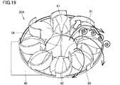
- FIG. 30 It is sectional drawing which shows a mode that the warm air is flowing through the inside of the blowing unit 30A in the modification of Embodiment 2. It is a figure which shows a mode that the blowing unit 30 in Embodiment 3 is arrange
- FIG. It is a perspective view which shows the blowing unit 30B in Embodiment 4.
- FIG. It is a figure which shows a mode that the blowing unit 30B in Embodiment 4 is arrange
- FIG. It is a perspective view which shows the blowing unit 30C in Embodiment 5.
- FIG. It is a figure which shows a mode that the blowing unit 30C in Embodiment 5 is arrange
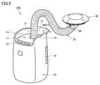
- the futon dryer 100 includes a main body unit 10 that generates hot air, a hose 20 (FIG. 2) connected to the main body unit 10, and a blowout provided at the tip of the hose 20. Unit 30.
- the main unit 10 has a substantially rectangular parallelepiped shape.
- An installation part 11 is provided on the upper part of the main unit 10.
- An operation unit 12 is provided on the front side (front side) of the installation unit 11.
- An opening 17 (FIG. 2) is provided in the upper part of the main unit 10.
- the hose 20 has flexibility and can be expanded and contracted. The hose 20 is taken in and out of the main unit 10 through the opening 17.
- a power cord (not shown) is also provided on the back side of the main unit 10.
- the hose 20 of the present embodiment is configured such that the length drawn from the opening 17 is variable.
- the hose 20 of the present embodiment is formed in a bellows shape that can hold a bent shape by a resin molded product, and the length of the drawer 17 from the opening 17 is changed by expansion and contraction.
- the outer diameter of the hose 20 is set to, for example, about 60 mm to 70 mm so that the user can easily grasp and pull it out.
- Shield portions 13 and 14 are provided on the left and right of the installation portion 11, respectively.
- the shielding parts 13 and 14 are located on the opposite sides of the installation part 11 and face each other.
- a shielding part 15 (FIG. 2) is provided on the back side of the installation part 11.
- the lower end of the shielding part 15 is pivotally supported so that the shielding part 15 can rotate in the direction indicated by the arrow AR15 (FIG. 2).
- the shielding part 15 When pulling out the hose 20 to the back side, the shielding part 15 is inclined to the back side with the lower end side as a center as necessary.
- the installation part 11 is formed above the opening 17 and at a position inside the shielding parts 13-15.
- the blowing unit 30 can be detachably installed on the installation unit 11.
- the shielding units 13 to 15 surround a part of the periphery of the blowing unit 30 installed in the installation unit 11. In the present embodiment, the shielding parts 13 to 15 surround a range of about 270 ° around the blowing unit 30 installed in the installation part 11. Even when the blowing unit 30 is installed in the installation unit 11, the blowing unit 30 can blow out hot air supplied from the main unit 10.
- a suction port 16 is provided on the back surface of the main unit 10.
- the main unit 10 incorporates a blower and a heater.
- the main unit 10 takes air into the interior through the suction port 16 and heats the air.
- the heated air is sent to the blowing unit 30 through the hose 20 as warm air (airflow).
- the main unit 10 and the hose 20 may be provided with a function of adding ions having deodorizing, sterilizing, and sterilizing effects to the warm air.
- FIG. 3 is a side view showing the blowing unit 30.
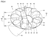
- FIG. 4 is a perspective view showing a state in which the cover unit 50 described later is not shown in the blowing unit 30.
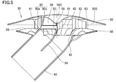
- 5 and 6 are a cross-sectional view and a cross-sectional perspective view showing the blowing unit 30, respectively.
- 7 is a cross-sectional perspective view taken along the line VII-VII in FIG.
- the blowing unit 30 is detachably provided at the tip of the hose 20 (FIG. 2), and can blow out hot air flowing through the hose 20.
- the blowout unit 30 of the present embodiment includes a cylindrical handle 40, a cover 50 (FIGS. 3, 5, and 6), a hook 60, a central guide plate 54 (FIGS. 4 to 7), and an upper guide plate. 56 and 57 (FIG. 4), and a plurality of partition walls 80 to 84 (FIG. 4).
- the cylindrical handle portion 40 has a cylindrical shape (here, a cylindrical shape) and is connected to the tip of the hose 20 by a fitting structure, a locking structure, or the like.
- the tubular handle 40 is fitted to the tip of the hose 20 using a locking claw 39 (FIG. 2) that is fitted on the tip of the hose 20 and can be tilted in the radial direction.
- the cylindrical handle 40 may be connected to the hose 20 so as to be rotatable in the circumferential direction.
- the cover 50 is connected to the distal end 42 (FIGS. 4 to 7) of the cylindrical handle 40 via partition walls 80 to 84 and a hook-like portion 60 described later. Is done.
- the cover portion 50 is provided so as to cover the distal end opening at a position away from the distal end opening of the cylindrical handle portion 40 (opening portion formed inside the distal end 42), and is substantially umbrellad as a whole together with the cylindrical handle portion 40. It has a shape of a shape.
- the cover part 50 has a circular outer edge centered on the central axis 50C. If the distance from the tip 42 of the cylindrical handle 40 is defined as the height in the direction of the central axis 50C, the height of the cover 50 is gradually increased from the outer peripheral portion toward the central portion.
- the central portion has a curved plate shape that bulges in a convex shape.
- a convex portion 58 is formed at the center of the inner surface 50S side of the cover portion 50 (the surface on the side of the cover portion 50 where the bowl-shaped portion 60 is located).
- the convex portion 58 has a shape that bulges out in a truncated cone shape toward the side where the cylindrical handle portion 40 is located.
- the cover portion 50 has the shape of an umbrella-shaped fabric portion (portion that is protected from rain when the umbrella is opened), and the cylindrical handle portion 40 is an umbrella. The shape of the shape handle portion is exhibited.
- the cylindrical handle 40 extends in a direction that intersects the direction of the central axis 50 ⁇ / b> C of the cover 50.
- the front end side (the right side in FIG. 5) in the direction in which the tubular handle 40 extends toward the front end 42 is defined as “front side”.
- the tip side of the cylindrical handle 40 extending in the direction away from the tip 42 starting from the tip 42 (the side of the cylindrical handle 40 connected to the hose 20) (see FIG. 5) (Left side) is defined as “rear side”.
- the hook-like portion 60 extends in the circumferential direction so as to surround the cylindrical handle portion 40 and is disposed so as to face the cover portion 50 with a space therebetween.
- the bowl-shaped part 60 forms a hot air flow path between the cover part 50 and the bowl-shaped part 60.
- a plurality of flow paths that are divided from each other by the partition walls 80 to 84 are formed between the cover portion 50 and the bowl-shaped portion 60.
- the bowl-shaped portion 60 extends from the tip 42 of the cylindrical handle portion 40 toward the outer side in the radial direction, and has a circular outer edge.
- the outer edge of the bowl-shaped part 60 is coaxial with the outer edge of the cover part 50, and has a circular shape centered on the central axis 50C.
- the outer diameter of the bowl-shaped portion 60 is smaller than the outer diameter of the cover portion 50 (FIG. 5).
- convex portions 61 to 68 are formed on the upper surface of the hook-shaped portion 60 (the surface of the hook-shaped portion 60 on the side close to the cover portion 50).
- the convex surface portions 61 to 68 are arranged at substantially the same interval in the circumferential direction with the central axis (center axis 50C) of the bowl-shaped portion 60 as the center.
- the partition walls 80 to 84 are provided so as to stand on the upper surface of the bowl-shaped portion 60 (the surface of the bowl-shaped portion 60 on the side close to the cover portion 50).
- Each of the partition walls 80 to 84 has a plate shape, and is along a direction (vertical direction in FIG. 5) parallel to the central axis of the bowl-shaped portion 60 (the central axis 50C of the cover portion 50). And extending between the hook-shaped portion 60 and the cover portion 50.
- the partition walls 81 to 84 are arranged so as to extend radially from the inner side to the outer side in the radial direction around the position of the tip 42 of the cylindrical handle 40.
- the partition walls 81 to 84 are formed to be curved in an arc shape from the inner end portion toward the outer end portion.
- the curvature center of the curved shape of the d partition walls 81 to 84 is located on the front side (the right side in FIG. 4 to FIG. 6) with respect to the tip 42 of the cylindrical handle 40 (FIG. 4). reference).
- the partition walls 81 and 84 are located on opposite sides of the distal end 42 of the cylindrical handle 40 in the radial direction of the bowl-shaped portion 60.
- the partition wall 81 is located between the convex surface portions 61 and 62
- the partition wall 84 is located between the convex surface portions 65 and 66.
- the partition wall 82 is on the front side of the partition wall 81 and is located between the convex surface portions 62 and 63.
- the partition wall 83 is on the front side of the partition wall 84 and is located between the convex surface portions 64 and 65.
- a partition wall is not provided between the two convex surface portions 63 and 64 located on the most front side of the convex surface portions 61 to 68.
- the convex surface parts 63 and 64 are adjacent to each other without a partition wall.
- the convex surface portions 67 and 68 are located on the rear side of the partition wall 80, and no partition wall is provided between the convex surface portions 67 and 68.
- the convex portions 67 and 68 are adjacent to each other without a partition wall.
- the partition wall 80 includes partition portions 80a and 80b and a connection portion 80c extending so as to connect the partition portions 80a and 80b.
- the connection portion 80c of the partition wall 80 is provided so as to stand on the rear side of the distal end 42 of the cylindrical handle portion 40 (FIG. 5).
- the partition portion 80 a of the partition wall 80 is located between the convex surface portions 61 and 68. Similarly to the partition walls 81 and 82, the partition portion 80a is disposed so as to extend from the inner side to the outer side in the radial direction, and is formed to be curved in an arc shape from the inner side to the outer side. Similarly to the partition walls 81 and 82, the partition portion 80a is curved so that the portion between the inside and the outside recedes toward the rear side.
- the partition part 80 b of the partition wall 80 is located between the convex surface parts 66 and 67.
- the partition portion 80b is disposed so as to extend from the inner side to the outer side in the radial direction, and is formed to be curved in an arc shape from the inner side to the outer side.
- the partition portion 80b is curved so that the portion between the inside and the outside recedes toward the rear side.
- the central guide plate 54 is provided inside the cylindrical handle 40.
- a portion of the central guide plate 54 that is disposed on the upstream side (the lower side in the drawing in FIG. 5) of the cylindrical handle 40 has a substantially flat plate shape. It extends in a direction substantially parallel to the axial direction.
- a portion of the central guide plate 54 disposed on the downstream side (upper side in FIG. 5) of the cylindrical handle 40 has a curved plate shape and is formed in the cover 50. It extends so as to approach the top of the convex portion 58.
- the central guide plate 54 has a front end opening (a portion located near the front end 42 in the flow path formed by the cylindrical handle 40) formed on the inner side of the front end 42 of the cylindrical handle 40 on the front side. It arrange
- a branch portion 55 (FIGS. 5 to 7) is formed at the upper end of the central guide plate.
- the branch portion 55 has a shape extending from the front side toward the rear side starting from the upper end portion located on the front side of the central guide plate 54, and the front end (rear end) of the branch portion 55 in the extending direction. ) Is connected to the connecting portion 80 c of the partition wall 80.
- the upper guide plates 56 and 57 are disposed above the central guide plate 54, and are disposed so as to exhibit a substantially V-shape as a whole.
- the upper guide plates 56 and 57 extend upward with the branching portion 55 as a lower end, and are arranged so as to draw an arc while moving away from each other toward the upper side.
- the upper guide plate 56 (FIG. 7) extends in an arc shape toward the convex surface portion 61 starting from the branch portion 55, and the upper guide plate 57 (FIG. 4) starts from the convex portion 66 starting from the branch portion 55. It extends in the shape of an arc toward the side.
- FIG. 8 is a perspective view showing a use state of the futon dryer 100.
- the blowing unit 30 is removed from the installation unit 11.
- the blowing unit 30 is pulled out from the main body unit 10 together with the hose 20 and is inserted between the mattress 90 and the comforter 92.
- the cover portion 50 of the blowout unit 30 has a substantially umbrella shape as a whole together with the cylindrical handle portion 40.
- the part of the comforter 92 that is in contact with the cover part 50 follows the shape of the outer surface of the cover part 50. So that it is deformed.
- the hose 20 is placed on the mattress 90, and the cylindrical handle 40 provided at the tip of the hose 20 supports the cover 50 from below as a support.
- the comforter 92 is supported by the tubular handle 40 and the cover 50.
- the comforter 92 is supported by the tubular handle 40 and the cover 50 in the shape of a mountain tent.
- a space S having a sufficient width is formed between the mattress 90 and the comforter 92 and around the cover portion 50.
- the main unit 10 When the operation unit 12 (FIG. 8) is operated, the main unit 10 generates hot air, and the hot air is supplied to the blowing unit 30 through the hose 20.
- the hot air is blown out from the tip opening of the cylindrical handle 40 (opening inside the tip 42), and is turned so as to contact the inner surface 50S (FIGS. 5 and 6) of the cover 50 and go outward in the radial direction.
- the warm air passes through a flow path formed between the inner surface 50S of the cover part 50 and the upper surface of the bowl-shaped part 60, and then passes through an opening between the outer edge of the cover part 50 and the outer edge of the bowl-shaped part 60. It passes through and is finally blown out from the blowing unit 30 toward the space S.
- FIG. 10 shows a state in which hot air is flowing inside the blowout unit 30, and is a cross-sectional perspective view corresponding to FIG.
- the warm air that has entered the tubular handle 40 from the hose 20 is warm air (arrow AR1) that flows through the flow path on the rear side of the central guide plate 54 and the front side of the central guide plate 54.
- warm air (arrows AR2 and AR3) flowing through the flow path.
- the warm air that has flowed through the flow path on the rear side of the central guide plate 54 is warm air that flows toward the upper guide plate 56 with the branch portion 55 (FIG. 11) as a branch point. It is further divided into an arrow AR1 in FIG. 12 and warm air (arrow AR6 in FIG. 12) flowing on the upper guide plate 57 (FIG. 12) side.
- the warm air (arrow AR1 in FIG. 12) that has flowed toward the upper guide plate 56 comes into contact with the inner surface 50S (FIG. 11) of the cover portion 50 and is turned.
- the warm air passes through a flow path defined by the convex surface portion 61, the partition wall 81, the partition portion 80a, and the inner surface 50S of the cover portion 50, and then blows out toward the space S (FIG. 9). Is blown out.
- the warm air (arrow AR6 in FIG. 12) that has flowed to the upper guide plate 57 side is also turned in contact with the inner surface 50S (FIG. 11) of the cover portion 50.
- the warm air passes through the flow path partitioned by the convex surface portion 66, the partition wall 84, the partition portion 80b, and the inner surface 50S of the cover portion 50, and then is directed toward the space S (FIG. 9). Is blown out.
- the hot air flowing through the flow path on the front side of the central guide plate 54 is turned in contact with the inner surface 50S (FIG. 11) of the cover portion 50, and then between the partition walls 81 and 82.
- the flow path between the partition walls 82 and 83 (arrow AR3, AR4, AR10), and the flow path between the partition walls 83 and 84 (arrow AR5), the space S (FIG. It will be blown out from the blowing unit 30 toward 9).
- no partition wall is provided between the convex surface parts 63 and 64.
- the flow path between the partition walls 82 and 83 is wider than the flow path between the partition walls 81 and 82 and the flow path between the partition walls 83 and 84.
- Each of the partition walls 82 and 83 is curved forward so that a portion between the inner side and the outer side is retracted toward the rear side, and more parts are passed through the flow path between the partition walls 82 and 83. Hot air is blown out to the front side.
- the cylindrical handle portion 40 provided at the tip of the hose 20 has a substantially umbrella shape as a whole together with the cover portion 50. Since the tubular handle portion 40 supports the cover portion 50 from below as a support, the comforter 92 is supported by the tubular handle portion 40 and the cover portion 50, and between the mattress 90 and the comforter 92 and the cover portion 50. It is possible to form a space S having a sufficient width at a peripheral position. In this state, warm air is blown out toward the space S through the blowing unit 30, and the warm air can reach all corners of the mattress 90 and the comforter 92. As a result, it is sufficient in a short time compared to the conventional case. A good drying effect.
- the futon dryer 100 since it is not necessary to configure the futon dryer 100 so as to have a size and blowing capacity larger than originally required for drying the futon, it is possible to reduce the size of the entire apparatus. It becomes possible.
- it is not necessary to incorporate a high-performance blower or heater in the main unit 10 since it is not necessary to incorporate a high-performance blower or heater in the main unit 10, it is possible to reduce product costs, reduce noise, and reduce electricity costs.
- the convex surface portions 61 to 68 are located on the side where the cover portion 50 is located (the inner side of the flow path). It may have a curved surface shape that bulges toward the projection (see FIG. 5). Moreover, the part which forms each of the some flow path among the inner surfaces 50S of the cover part 50 may have the curved surface shape which recedes concavely from the inner side of a flow path (refer FIG. 5). In the warm air passing through each flow path, lift is generated by the curved surface shape of the convex portions 61 to 68, and the reaction force as shown by the white arrow in FIG. The reach of hot air can be made longer by the pressure.
- the direction of the warm air passing through each flow path can be smoothly changed by the curved surface shape of the inner surface 50S of the cover portion 50, and as a result, the warm air is caused by friction with the inner surface 50S. It is possible to suppress a decrease in the reach distance.
- the convex surface portions 61 to 68 (portions of the bowl-shaped portion 60 forming each of the plurality of flow paths) form a separate spindle shape or a part of the spindle shape for each flow path. You may do it. According to this configuration, a vertical vortex (see FIG. 19) can be generated in each of the plurality of flow paths, and as a result, the reach distance of the hot air can be further extended.
- FIG. 13 is a side view showing a state in which hot air is flowing inside the blowing unit 30 in the first modification of the first embodiment.
- the inner surface 50S of the cover portion 50 has a hot air blown from the tip opening (inner opening of the tip 42) of the cylindrical handle 40 and turned to contact the inner surface 50S at 45 ° or more. It is good to form so that it may turn toward the outer side of radial direction by these angle (theta) 1, (theta) 2.
- warm air can be sent out more widely using the space formed between the mattress and the comforter, and it becomes possible to dry a mattress and a comforter more efficiently over a wide range.
- FIG. 13 shows a state in which hot air is blown from the entire circumference (a range including the rear side) of the blowing unit 30, the hot air is blown from the blowing unit as in the case of the first embodiment.
- You may be comprised so that it may blow out only from a part of circumference
- the direction of warm air flowing through the inside of the tubular handle 40 corresponding to the central axis 40C of the tubular handle 40
- the angle formed by the wind direction is 45 ° or more at any location in the circumferential direction.
- the angle ⁇ 1 is 60 ° and the angle ⁇ 2 is 150 °.
- FIG. 14 is a cross-sectional view showing a state in which hot air is flowing inside the blowing unit 30 in the second modification of the first embodiment.
- the flow path cross-sectional area of the portion at a position of a predetermined diameter centered on the central axis 50 ⁇ / b> C of the cover portion 50 The total sum may be configured to gradually increase from the inner side to the outer side in the radial direction.
- the diameter D40 of the flow path formed inside the cylindrical handle 40 is 64 mm.
- the position P50 having a diameter of 50 mm centered on the central axis 50C is used.
- the channel cross-section height D50 (the height of the channel cross-section orthogonal to the flow direction of the streamline ST) is 34 mm.
- the channel cross-sectional height D100 at a position P100 having a diameter of 100 mm centered on the central axis 50C is 21 mm.
- the flow path cross-sectional height D150 at a position P150 having a diameter of 150 mm centered on the central axis 50C is 16 mm.
- the channel cross-sectional height D175 at a position P175 having a diameter of 175 mm centered on the central axis 50C is 15 mm.
- the channel cross-sectional height D200 at the position P200 having a diameter of 200 mm centered on the central axis 50C is 14 mm. That is, of the flow paths formed between the inner surface 50S of the cover part 50 and the bowl-shaped part 60, the flow path cross-sectional height at the position of a predetermined diameter centered on the central axis 50C of the cover part 50 is the diameter.
- the flow path is closed by the partition wall 80 in the rear 90 ° range, and the flow path is formed in the front 270 ° range, as in the case shown in FIG. ing.
- the sum total of the flow path cross-sectional areas of the portions at a predetermined diameter centered on the central axis 50C is the cylindrical handle portion.
- the position P100 having a diameter of 100 mm is approximately 4860 mm 2
- the position P150 having a diameter of 150 mm centered on the central axis 50C is approximately 5650 mm 2
- the position P175 having a diameter of 175 mm centered on the central axis 50C is approximately 6040 mm 2
- the central axis 50C of about 6440mm 2 at positions P200 diameter 200mm around the.
- the channel cross-sectional area (3220 mm 2 ) having a diameter D40 formed inside the cylindrical handle 40 gradually increases from the inner side to the outer side in the radial direction, and has a diameter of 200 mm with the central axis 50C as the center.
- the opening portion extending in the circumferential direction at the position P200 (channel cross-sectional height D200) (the sum of the channel cross-sectional areas of the opening portion) is doubled (6440 mm 2 ). According to the said structure, it becomes possible to convert the kinetic energy of the warm air which blows off from the inner side opening of the front-end
- the rate of change is greater than 0 and substantially constant. It should be a value.
- the total cross-sectional area of the flow path is Y (mm 2 ) and the predetermined diameter centered on the central axis 50C is X (mm)
- Y 16.2X + 3220 is a linear approximation.
- the formula holds.
- the case where the rate of change is substantially constant includes the case where the rate of change is completely constant. The rate of change is substantially constant.
- the rate of change of the cross-sectional area of the flow path every time the diameter increases by 50 mm is based on the change rate reference (here 16.2) given by the linear approximation as described above. It can be defined to be ⁇ 10% or less. According to the configuration in which the rate of change is substantially constant, it becomes possible to convert the kinetic energy of the hot air blown from the inner opening of the tip 42 of the cylindrical handle 40 into the static pressure for sending the hot air with higher efficiency. It is possible to increase the reach of hot air.
- the rate of change is defined as the rate of change in which the total sum of the channel cross-sectional areas increases as the predetermined diameter centered on the central axis 50C increases.
- the rate of change is defined as follows: May be. That is, a streamline ST is drawn in a flow path formed between the cover part 50 and the bowl-shaped part 60, and a position corresponding to the tip 42 of the streamline ST is set as a starting point, and from the starting point on the streamline ST. Assuming that the curve length of the streamline up to an arbitrary position is defined as a predetermined distance, the rate of change in which the sum of the channel cross-sectional areas increases as the predetermined distance increases may be defined as the rate of change. .
- the curve length is about 26.9 mm, and the sum of the flow path cross-sectional areas at the position P50 is about 4055 mm 2 .
- the curve length is about 52.6 mm, and the sum of the flow path cross-sectional areas at the position P100 is about 4860 mm 2 .
- the curve length is about 78.0 mm, and the sum of the flow path cross-sectional areas at the position P150 is about 5650 mm 2 .
- the curve length is about 90.6 mm, and the sum of the flow path cross-sectional areas at the position P175 is about 6040 mm 2 .
- the curve length is about 103.1 mm, and the sum total of the flow path cross-sectional areas at the position P200 is about 6440 mm 2 .
- the rate of change is 31.2 and is configured to take a substantially completely constant value. Even with this configuration, it becomes possible to convert the kinetic energy of the hot air blown from the inner opening of the tip 42 of the cylindrical handle 40 into the static pressure for sending the hot air with higher efficiency, and the reach distance of the hot air Can be made longer.
- the convex surface portions 61 to 68 are on the side where the cover portion 50 is located (inside the flow path). It has a curved surface shape that bulges toward the top.
- a portion (a portion corresponding to the convex surface portions 61 to 68) forming each of the plurality of flow paths in the bowl-shaped portion 60 is as follows. You may form in the flat plane shape without an unevenness
- the channel cross-sectional area increases toward the outside in the radial direction.
- the flow path cross-sectional height is configured to be gradually lower, the kinetic energy of the hot air blown from the inner opening of the tip 42 of the cylindrical handle 40 is changed to a static pressure that sends out the hot air. Further, conversion can be performed with high efficiency, and the reach of hot air can be made longer.
- FIG. 15 is a perspective view showing another usage mode of the futon dryer 100 according to the first embodiment. Even when the blowing unit 30 is installed in the installation unit 11, the blowing unit 30 can blow out hot air supplied from the main unit 10 through the hose 20.
- the futon dryer 100 can be used, for example, as a heater for warming a user's fingers or an indoor space. When the futon dryer 100 can generate ions or the like, the futon dryer 100 can also have the function of an air cleaner.
- FIG. 16 is a perspective view showing still another usage mode of the futon dryer 100 according to the first embodiment.
- the futon dryer 100 can also be used as a clothes dryer for drying clothes, for example.
- the futon dryer 100 can also have functions of sterilization, sterilization, and deodorization of clothes.
- the present invention is not limited to clothes, and may be sterilized, sterilized, or deodorized for furniture such as chiffon.
- General duvet dryers have little use other than drying futons, and there are fewer opportunities to dry futons in winter compared to summer. Futon dryers have a low operating rate in the winter, and the futon dryer may not be used at all in the winter.
- the futon dryer 100 described in the above embodiment not only has a high futon drying capacity when used as a futon dryer, but also has a high heating capacity (especially long hot air) when used as a heater. Reachable distance), and when used as a clothes dryer, it is possible to obtain a high clothes drying ability (particularly a long reach distance of hot air). That is, according to the futon dryer 100 as described above, a high commercial value can be exhibited.
- the main unit 10 has shielding portions 13 to 15 that surround a part of the periphery of the blowing unit 30 installed in the installation portion 11.
- the shielding portion 15 configured to be unrotatable is illustrated.
- the structure that the shielding part 15 is rotatable may be adopted as necessary.
- FIGS. 17 and 18 are a cross-sectional view showing a state in which hot air is blown out in a state where the blowing unit 30 of the futon dryer 100 is installed in the installation unit 11 (FIGS. 15 and 16) of the main body unit 10, respectively. It is a cross-sectional perspective view.
- the warm air blown from the blow-out unit 30 toward the left and right direction and the rear side of the main unit 10 is turned in contact with the shielding portions 13 to 15 and blown to the front side (front side) of the main unit 10.
- the warm air is blown out only from a part around the blowing unit 30 (for example, from a range of 270 °).
- the amount of warm air blown from the blowing unit 30 toward the rear side of the main unit 10 may be small or not at all. .
- partition walls 80 to 84 are provided between the cover portion 50 and the bowl-shaped portion 60.
- the partition walls 80 to 84 form a plurality of flow paths between the cover part 50 and the bowl-shaped part 60, and define the blowing direction of hot air. That is, the presence of the partition wall 80 prevents the warm air blown from the inner opening of the tip 42 of the cylindrical handle 40 from flowing toward the rear side of the partition wall 80. The warm air blown from the inner opening of the tip 42 of the cylindrical handle 40 flows more to the flow path formed on the front side of the partition wall 80.
- each said structure when using the futon dryer 100 as a heater which heats a user's finger
- FIG. 19 is a perspective view illustrating a state where the cover unit 50 is not illustrated in the blowing unit 30A of the second embodiment, and corresponds to FIG. 12 in the first embodiment.
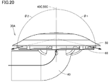
- FIG. 20 is a side view showing a state in which warm air is flowing inside the blowing unit 30A in the second embodiment.
- the blowing unit 30 in the first embodiment is different from the blowing unit 30A in the second embodiment in the following points.
- the cover unit 50 is not shown in FIG. 19, but the blowout unit 30A in the second embodiment includes the cover unit 50 (FIG. 20) having the same configuration as that in the first embodiment.
- the cylindrical handle 40 has a shape that is curved in an approximately L shape (at an angle of about 90 °) as a whole, and the central axis 40C of the inner opening of the tip 42 (FIG. 19) of the cylindrical handle 40. Extends so as to coincide with the central axis 50 ⁇ / b> C of the cover portion 50.
- the warm air is blown out only from a part around the blowing unit 30 (for example, from a range of 270 °).
- the blowing unit 30A according to the second embodiment as shown in FIG. 19, warm air is blown out from the entire circumference (a range including the rear side) of the blowing unit 30.
- the convex portion 61 and the partition wall 81 having substantially the same shape are formed side by side in the circumferential direction so as to surround the periphery of the tip 42 of the cylindrical handle portion 40.
- the central guide plate 54 has a front end opening (a portion located near the front end 42 in the flow path formed by the cylindrical handle 40) formed on the inner side of the front end 42 of the cylindrical handle 40 on the front side. It arrange
- the upper guide plates 56 and 57 are not employed.
- the hot air flowing through the flow path on the front side of the central guide plate 54 is turned in contact with the inner surface 50S (FIG. 11) of the cover portion 50 (not shown), and then arranged on the front side of the bowl-shaped portion 60 and adjacent to each other. It passes through the flow path formed between two matching partition walls 81 (front side) and is blown out from the blowing unit 30 toward the space S (FIG. 9).
- the hot air flowing through the flow path on the rear side of the central guide plate 54 is turned in contact with the inner surface 50S (FIG. 11) of the cover portion 50 (not shown) and then disposed on the front side of the bowl-shaped portion 60. Then, it passes through a flow path formed between two partition walls 81 adjacent to each other, and is blown out from the blowing unit 30 toward the space S (FIG. 9).
- the cylindrical handle portion 40 provided at the tip of the hose 20 has a substantially umbrella shape as a whole together with a cover portion 50 (not shown). Since the tubular handle 40 supports the cover 50 from below as a support, the comforter 92 (FIG. 9) is supported by the tubular handle 40 and the cover 50, and between the comforter 90 and the comforter 92. A space S (FIG. 9) having a sufficient width can be formed at a position around the cover portion 50. In this state, warm air is blown out toward the space S through the blowing unit 30A, and the warm air can reach all corners of the mattress 90 and the comforter 92. A good drying effect.
- the futon dryer it is not necessary to configure the futon dryer so as to have a size and blowing capacity larger than those originally required for drying the futon, and thus it is possible to reduce the size of the entire apparatus. Become.
- a high-performance blower or heater since it is not necessary to incorporate a high-performance blower or heater in the main unit 10, it is possible to reduce product costs, reduce noise, and reduce electricity costs.
- the diameter of the tip opening of the hose 20 was ⁇ 64 mm.
- the horizontal width of the tip opening of the hose 20 was 125 mm, the height of the tip opening was 15 mm, and the length of the tip opening was 110 mm.
- the diameter was 200 mm, and the height of the blowing opening of the blowing unit 30A was 14 mm.
- one mattress and two comforters were prepared. 100 g of water was sprayed on one quilt and the quilt located on the lower side of the two quilts (total of 200 g). These three futons were superposed and dried using the futon dryer. The amount of warm air was set to about 0.6 m 3 / min, the temperature of the warm air was set to about 55 ° C., and the drying time was set to 60 minutes. The drying performance was verified based on the weight difference between the samples before and after drying.
- the average value of the weight difference between the samples before and after drying was 172 g (drying rate: 86%).
- the average value of the weight difference between the samples before and after drying was 186 g (drying rate 93%).
- the blowing unit 30A has a drying performance that is 8% or more higher than that of the comparative example. According to the blowout unit 30A of the second embodiment, since it is open over the entire periphery of the blowout unit 30A, the load of the blower fan is reduced even when a part of the opening is closed by the comforter. Can do.
- the convex portion 61 (the portion forming each of the plurality of flow paths in the bowl-shaped portion 60) is on the side where the cover section 50 is located (the inner side of the flow path). You may have the curved-surface shape which bulges toward convex. Moreover, the part which forms each of the some flow path among the inner surfaces of the cover part 50 may have the curved surface shape which recedes concavely from the inner side of a flow path. In the warm air passing through each flow path, lift force as shown by the white arrow in FIG. 19 is generated by the curved surface shape of the convex surface portion 61, and the reach of the warm air is further increased by the reaction force (differential pressure due to lift force). Can be long. Moreover, the direction of the warm air passing through each flow path can be smoothly changed by the curved surface shape of the inner surface of the cover 50, and as a result, the reach distance of the warm air due to friction with the inner surface Can be suppressed.
- the convex portion 61 (the portion of the bowl-shaped portion 60 forming each of the plurality of flow paths) forms a separate spindle shape or a part of a spindle shape for each flow path. May be. According to this configuration, a vertical vortex (see FIG. 19) can be generated in each of the plurality of flow paths, and as a result, the reach distance of the hot air can be further extended.
- the inner surface of the cover portion 50 has an angle of 45 ° or more when the hot air blown out from the distal end opening (inner opening of the distal end 42) of the cylindrical handle 40 and is turned in contact with the inner surface. It may be formed so as to be turned outward in the radial direction at ⁇ 1 and ⁇ 2. According to the said structure, warm air can be sent out more widely using the space formed between the mattress and the comforter, and it becomes possible to dry a mattress and a comforter more efficiently over a wide range.
- FIG. 20 shows a state in which hot air is blown out from the entire circumference (range including the rear side) of the blowing unit 30A, but the hot air is blown out as in the case of the first embodiment.
- You may be comprised so that it may blow out only from a part of circumference
- the direction of warm air flowing through the inside of the tubular handle 40 corresponding to the central axis 40C of the tubular handle 40
- the angle formed by the wind direction is 45 ° or more at any location in the circumferential direction. In the example shown in FIG. 20, the angles ⁇ 1 and ⁇ 2 are both 105 °.
- FIG. 21 is a cross-sectional perspective view showing a blowout unit 30A in a modification of the second embodiment.
- FIG. 22 is a cross-sectional view showing a state in which hot air is flowing inside the blowing unit 30A according to a modification of the second embodiment.
- the flow path cross-sectional area of the portion at a position of a predetermined diameter centered on the central axis 50 ⁇ / b> C of the cover portion 50 The total sum may be configured to gradually increase from the inner side to the outer side in the radial direction.
- the diameter D40 of the flow path formed inside the cylindrical handle 40 is 64 mm.
- the position P50 having a diameter of 50 mm centered on the central axis 50C is used.
- the channel cross-section height D50 (the height of the channel cross-section orthogonal to the flow direction of the streamline ST) is 28 mm.
- the channel cross-sectional height D100 at a position P100 having a diameter of 100 mm with the center axis 50C as the center is 16 mm.
- the channel cross-sectional height D150 at a position P150 having a diameter of 150 mm centered on the central axis 50C is 12 mm.
- the channel cross-sectional height D175 at a position P175 having a diameter of 175 mm centered on the central axis 50C is 11 mm.
- the channel cross-sectional height D200 at a position P200 having a diameter of 200 mm centered on the central axis 50C is 10 mm. That is, of the flow paths formed between the inner surface 50S of the cover part 50 and the bowl-shaped part 60, the flow path cross-sectional height at the position of a predetermined diameter centered on the central axis 50C of the cover part 50 is the diameter.
- the rate of change in which the total sum of the cross-sectional areas of the flow path increases as the predetermined diameter centered on the central axis 50C increases, the rate of change is greater than 0 and substantially constant. It should be a value. According to the said structure, it becomes possible to convert the kinetic energy of the warm air which blows off from the inner side opening of the front-end
- FIG. 23 is a diagram illustrating a state in which the blowing unit 30 ⁇ / b> A according to Embodiment 3 is disposed between the mattress 90 and the comforter 92.
- the blowing units 30A of the second and third embodiments are viewed alone, they have the same configuration.
- the blowout unit 30 ⁇ / b> A is arranged so that the outer surface of the cover unit 50 contacts the mattress 90 in a state where the cover unit 50 and the tubular handle 40 are inserted between the mattress 90 and the comforter 92. It can also be arranged. This arrangement can be applied to any of the blowing units of the first and second embodiments.
- the blowing unit 30A When such an arrangement state is adopted, the blowing unit 30A is placed on the mattress 90, and the blowing unit 30A is a cylindrical shape provided at the tip of the hose 20 and the tip of the hose 20 as a support.
- the handle 40 is supported from below. Even in the arrangement state, the comforter 92 is supported by the tubular handle 40 and the cover 50.
- a space S having a sufficient size is formed between the mattress 90 and the comforter 92 and around the cover portion 50.
- the warm air is blown out from the blowing unit 30A toward the space S, and the warm air can reach all the corners of the mattress 90 and the comforter 92.
- sufficient drying can be achieved in a short time compared to the conventional case. An effect can be obtained.
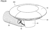
- FIG. 24 is a perspective view showing a blowing unit 30B in the fourth embodiment.
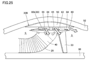
- FIG. 25 is a diagram illustrating a state where the blowing unit 30 ⁇ / b> B according to Embodiment 4 is disposed between the mattress 90 and the comforter 92.
- the blowing unit 30 ⁇ / b> B further includes a support mechanism 33.
- the support mechanism 33 in the present embodiment has a curved plate shape, and is provided on the outer surface located on the opposite side to the cover portion 50 in the bowl-shaped portion 60.
- the cylindrical handle 40 cooperates with the support mechanism 33 to support the cover 50 from below as a support.
- the comforter 92 is supported by the support mechanism 33, the cylindrical handle 40, and the cover 50, and a space S having a sufficient width is formed between the mattress 90 and the comforter 92 and around the cover 50. be able to.
- warm air is blown out toward the space S through the blowing unit 30B, and the warm air can reach all corners of the mattress 90 and the comforter 92. As a result, it is sufficient in a short time compared to the conventional case. A good drying effect.
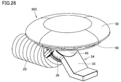
- FIG. 26 is a perspective view showing a blowing unit 30C in the fifth embodiment.
- FIG. 27 is a diagram illustrating a state where the blowing unit 30 ⁇ / b> C according to the fifth embodiment is disposed between the mattress 90 and the comforter 92.
- the blowout unit 30 ⁇ / b> C also includes a support mechanism 33.
- the support mechanism 33 in the present embodiment has a support part 35 and a clamping part 36, and is detachably attached to the cylindrical handle part 40 using elastic deformation of the clamping part 36.
- the cylindrical handle 40 cooperates with the support mechanism 33 to support the cover 50 from below as a support.
- the comforter 92 is supported by the support mechanism 33, the cylindrical handle 40, and the cover 50, and a space S having a sufficient width is formed between the mattress 90 and the comforter 92 and around the cover 50. be able to.
- warm air is blown out toward the space S through the blowing unit 30C, and the warm air can reach all corners of the mattress 90 and the comforter 92. As a result, it is sufficient in a short time compared to the conventional case. A good drying effect.
- the support mechanism 33 When disposing the blowing unit 30C on the installation portion 11 (see FIGS. 1 and 2), the support mechanism 33 is appropriately removed from the cylindrical handle portion 40. It is also effective to provide a predetermined location where the support mechanism 33 can be accommodated in the main unit 10 or the support mechanism 33 can be hooked.
- the blowing unit is connected to the tip of the hose 20, but the blowing unit may be directly connected to the main unit 10 (air blowing duct) without using the hose 20.
- the blowing unit may be directly connected to the main unit 10 (air blowing duct) without using the hose 20.
- an opening may be arranged in the housing of the main unit 10, the downstream end of the air duct may be extended to the opening, and the blowout unit may be connected to the opening.
- the blowing unit 30 which protrudes from the housing of the main body unit 10 can be inserted between the mattress and the comforter to perform the futon drying.
Landscapes
- Engineering & Computer Science (AREA)
- Textile Engineering (AREA)
- Accessory Of Washing/Drying Machine, Commercial Washing/Drying Machine, Other Washing/Drying Machine (AREA)
- Drying Of Solid Materials (AREA)
Abstract
布団乾燥機に設けられ、温風を吹き出す吹出ユニット(30)であって、筒状の形状を有する筒状柄部(40)と、筒状柄部(40)の先端開口から離れた位置で先端開口を覆うように設けられ、筒状柄部(40)とともに全体として略傘状の形状を呈するカバー部(50)とを備え、敷布団(90)と掛布団(92)との間にカバー部(50)および筒状柄部(40)が挿入された状態では、カバー部(50)および筒状柄部(40)によって掛布団(92)が支持され、筒状柄部(40)の先端開口から吹き出された温風は、カバー部(50)の内面に接触して転向され、カバー部(50)および筒状柄部(40)によって敷布団(90)と掛布団(92)との間であってカバー部(50)の周囲の位置に形成された空間(S)に向けて吹き出される。掛布団と敷布団との間に十分な広さを有する空間を形成可能となる。
Description
本明細書に開示される技術は、布団乾燥機および吹出ユニットに関する。本出願は、2017年4月10日に出願した日本特許出願である特願2017-077507号に基づく優先権を主張する。当該日本特許出願に記載された全ての記載内容は、参照によって本明細書に援用される。
一般的な布団乾燥機は、本体ユニット、ホース、および乾燥マット(空気袋)を備える(特開平08-010499号公報)。本体ユニットは、ホースを通して乾燥マットの中に温風を供給する。乾燥マットが敷布団と掛布団との間で膨張することによって、敷布団および掛布団を効率よく乾燥させることが可能となる。このような布団乾燥機は、以下のような場合には十分な乾燥効果を得られないことがある。
たとえば、布団乾燥機の温風供給能力が弱い場合、掛布団の重量が想定よりも(ユーザーによって設定された温風出力値よりも)重い場合、および、乾燥マットが折れ曲がって配置されるなど、乾燥マットが布団間で正しく配置されていない場合などが挙げられる。これらの場合、乾燥マットが布団間で膨らみにくくなり、温風が乾燥マットの隅々にまで行き渡ることができず、布団を効率よく乾燥させることが難しくなる。
上記のような布団乾燥機は、乾燥マットを介した熱伝導を主な乾燥手段の1つとして利用している。乾燥マットは、乾燥マットの下方に位置する敷布団には密着しやすい。一方で掛布団は、乾燥マットの上方に位置し、柔軟で変形しやすい。乾燥マットは掛布団には密着しにくく、これらの間には隙間が形成されやすい。乾燥マットを介した掛布団への熱伝導はしばしば行なわれにくく、十分な乾燥効果が得られなかったり、長時間の乾燥のために電気代が高くなったりする。
乾燥マットを使用せずに布団を乾燥させることが可能な布団乾燥機も知られている(特開2016-064126号公報)。この公報に開示された布団乾燥機は、本体ユニットと、本体ユニットにホースを介して接続された吹出ユニット(乾燥ユニット)とを備えている。吹出ユニットは箱形状(略直方体の形状)を有し、吹出ユニットには温風を外部に吹き出すための複数の吹出口が設けられている。
吹出ユニットを敷布団と掛布団との間に配置した状態で布団が乾燥される。乾燥マット方式の布団乾燥機は、乾燥マットの形状や大きさ、および乾燥マットの設置状況等により制限を受けることがあるが、乾燥マットを使用しない上記のような布団乾燥機によれば、そのような制限を受けることなく布団を乾燥することができる。
乾燥マットを使用しない布団乾燥機においては、吹出ユニットが掛布団と敷布団との間に配置される。吹出ユニットは、掛布団と敷布団との間に形成された空間(隙間)に向けて温風を吹き出す。十分な広さを有する空間が掛布団と敷布団との間に形成されていない場合、吹出ユニットから吹き出された温風が布団の隅々にまで行き渡らず、結果として、十分な乾燥効果を得にくくなることがある。
特開2016-064126号公報に開示された吹出ユニット(乾燥ユニット)は、扁平な箱形状を有している。吹出ユニットの扁平な箱形状を積極的に利用したとしても、吹出ユニットの周囲に十分な広さを有する空間を形成することは容易ではない。布団乾燥機に慣れたユーザーであれば、吹出ユニットを掛布団と敷布団との間に配置した後に、掛布団を部分的に引っ張り上げて上記のような空間(掛布団のふくらみ)を布団間に形成することを思いつくかもしれないが、掛布団の自重でそのような空間は小さくなってしまう可能性がある。
その対策として、たとえば、布団乾燥のために本来的に要求される以上の大きさや送風能力を有するように布団乾燥機を構成することが考えられる。しかしながら、扁平な箱形状を有する吹出ユニットを大きくすることは、装置全体の大型化に繋がる。高性能の送風装置やヒーターなどを内蔵することも考えられるが、製品コストが高くなったり、騒音が大きくなったり、電気代が高くなったりする。
本明細書は、掛布団と敷布団との間に十分な広さを有する空間を形成することが可能な構成を備えた吹出ユニット、およびそのような吹出ユニットを備えた布団乾燥機を開示することを目的とする。
吹出ユニットは、布団乾燥機に設けられ、温風を吹き出す吹出ユニットであって、筒状の形状を有する筒状柄部と、上記筒状柄部の先端開口から離れた位置で上記先端開口を覆うように設けられ、上記筒状柄部とともに全体として略傘状の形状を呈するカバー部と、を備え、敷布団と掛布団との間に上記カバー部および上記筒状柄部が挿入された状態では、上記カバー部および上記筒状柄部によって上記掛布団が支持され、上記筒状柄部の上記先端開口から吹き出された温風は、上記カバー部の内面に接触して転向され、上記カバー部および上記筒状柄部によって上記敷布団と上記掛布団との間であって上記カバー部の周囲の位置に形成された空間に向けて吹き出される。
上記吹出ユニットにおいて、上記カバー部の上記内面は、上記筒状柄部の上記先端開口から吹き出されて上記内面に接触して転向される温風が45°以上の角度で転向されるように形成されてもよい。
上記吹出ユニットは、上記筒状柄部の周囲を取り囲むように周方向に延在し、上記カバー部に間隔を空けて対向するように配置され、上記カバー部との間に温風の流路を形成する鍔状部をさらに備え、上記流路のうち、上記カバー部の中心軸を中心とする所定直径の位置における部分の流路断面積の総和は、径方向の内側から外側に向かうにつれて徐々に大きくなっていてもよい。
上記吹出ユニットにおいて、上記所定直径が大きくなるにつれて上記流路断面積の上記総和が大きくなる変化の割合を変化率とすると、当該変化率は0より大きく、かつ略一定の値であってもよい。
上記吹出ユニットにおいて、上記カバー部の上記内面と上記鍔状部との間に形成される上記流路のうち、上記カバー部の中心軸を中心とする上記所定直径の位置での流路断面高さは、径方向の内側から外側に向かうにつれて徐々に小さくなるように構成されていてもよい。
上記吹出ユニットにおいて、上記カバー部と上記鍔状部との間には、仕切壁により互いに分割された複数の上記流路が形成されていてもよい。
上記吹出ユニットにおいて、上記鍔状部のうちの複数の上記流路の各々を形成している部分は、上記流路の内部側に向かって凸状に膨出する曲面形状を有しており、上記カバー部のうちの複数の上記流路の各々を形成している部分は、上記流路の内部側から凹状に後退する曲面形状を有していてもよい。
布団乾燥機は、温風を生成する本体ユニットと、上記本体ユニットに接続されたホースと、上記吹出ユニットとを備える。
上記布団乾燥機において、上記本体ユニットは、上記本体ユニットの上部に、上記吹出ユニットを着脱自在に設置できる設置部を有し、上記設置部に上記吹出ユニットが設置された状態で、上記ホースおよび上記吹出ユニットを通して温風が吹き出されてもよい。
上記布団乾燥機において、上記本体ユニットは、上記設置部に設置された上記吹出ユニットの周囲の一部を取り囲む遮蔽部を有し、上記吹出ユニットから上記本体ユニットの左右方向および後方に向けて吹き出された温風は、上記遮蔽部に接触して転向され、上記本体ユニットの正面側に吹き出されてもよい。
上記の構成によれば、吹出ユニットの傘形状を活用することで掛布団と敷布団との間に十分な広さを有する空間を形成することができる。
実施の形態について、以下、図面を参照しながら説明する。同一の部品および相当部品には同一の参照番号を付し、重複する説明は繰り返さない場合がある。
[実施の形態1]
(布団乾燥機100)
図1~図12を参照して、実施の形態1における布団乾燥機100および吹出ユニット30について説明する。図1および図2に示すように、布団乾燥機100は、温風を生成する本体ユニット10と、本体ユニット10に接続されたホース20(図2)と、ホース20の先端に設けられた吹出ユニット30とを備える。
(布団乾燥機100)
図1~図12を参照して、実施の形態1における布団乾燥機100および吹出ユニット30について説明する。図1および図2に示すように、布団乾燥機100は、温風を生成する本体ユニット10と、本体ユニット10に接続されたホース20(図2)と、ホース20の先端に設けられた吹出ユニット30とを備える。
(本体ユニット10およびホース20)
本体ユニット10は、略直方体の形状を有する。本体ユニット10の上部には、設置部11が設けられる。設置部11の正面側(手前側)には、操作部12が設けられる。本体ユニット10の上部には、開口部17(図2)が設けられる。ホース20は、可撓性を有し、伸縮可能である。ホース20は、開口部17を通して本体ユニット10の中に出し入れされる。本体ユニット10の背面側には、図示しない電源コードも設けられる。
本体ユニット10は、略直方体の形状を有する。本体ユニット10の上部には、設置部11が設けられる。設置部11の正面側(手前側)には、操作部12が設けられる。本体ユニット10の上部には、開口部17(図2)が設けられる。ホース20は、可撓性を有し、伸縮可能である。ホース20は、開口部17を通して本体ユニット10の中に出し入れされる。本体ユニット10の背面側には、図示しない電源コードも設けられる。
本実施の形態のホース20は、開口部17からの引出し長が可変に構成されている。本実施の形態のホース20は、樹脂成形品によって曲げ形状を保持可能な蛇腹状に形成されており、伸縮によって開口部17からの引出し長が変更される。ホース20の外径は、使用者が容易に把持して引き出し可能なように、たとえば60mm~70mm程度に設定される。
設置部11の左右には、それぞれ、遮蔽部13,14が設けられる。遮蔽部13,14は、設置部11を挟んで互いに反対側に位置し、相互に対向している。設置部11の背面側には、遮蔽部15(図2)が設けられる。遮蔽部15の下端は、遮蔽部15が矢印AR15(図2)に示す方向に回動可能なように軸支されている。ホース20を背面側に引き出す際に、遮蔽部15は必要に応じて下端側の部分を中心として背面側に傾けられる。
設置部11は、開口部17の上方であって且つ遮蔽部13~15の内側の位置に形成される。設置部11には、吹出ユニット30を着脱自在に設置できる。遮蔽部13~15は、設置部11に設置された吹出ユニット30の周囲の一部を取り囲む。本実施の形態においては、遮蔽部13~15は、設置部11に設置された吹出ユニット30の周囲の約270°の範囲を取り囲む。吹出ユニット30が設置部11に設置された状態であっても、吹出ユニット30は本体ユニット10から供給された温風を吹き出すことができる。
図2に示すように、本体ユニット10の背面には、吸込口16が設けられる。本体ユニット10は、送風機およびヒーターを内蔵している。本体ユニット10は、吸込口16を通して内部に空気を取り込み、空気を加熱する。加熱された空気は、ホース20を通して温風(気流)として吹出ユニット30に送られる。温風に消臭や殺菌、除菌効果を有するイオンを付加するような機能が本体ユニット10やホース20に備えられていてもよい。
(吹出ユニット30)
図3は、吹出ユニット30を示す側面図である。図4は、吹出ユニット30において、後述するカバー部50が図示されていない状態を示す斜視図である。図5および図6は、それぞれ、吹出ユニット30を示す断面図および断面斜視図である。図7は、図4におけるVII-VII線に沿った矢視断面斜視図である。
図3は、吹出ユニット30を示す側面図である。図4は、吹出ユニット30において、後述するカバー部50が図示されていない状態を示す斜視図である。図5および図6は、それぞれ、吹出ユニット30を示す断面図および断面斜視図である。図7は、図4におけるVII-VII線に沿った矢視断面斜視図である。
吹出ユニット30は、ホース20(図2)の先端に着脱可能に設けられ、ホース20を通流した温風を吹き出すことができる。本実施の形態の吹出ユニット30は、筒状柄部40、カバー部50(図3,図5,図6)、鍔状部60、中央ガイド板54(図4~図7)、上方ガイド板56,57(図4)、および、複数の仕切壁80~84(図4)を備える。
(筒状柄部40およびカバー部50)
筒状柄部40は、筒状(ここでは円筒状)の形状を有し、ホース20の先端に、嵌合構造および係止構造などによって接続される。たとえば、筒状柄部40は、ホース20の先端に外嵌され、径方向に傾倒可能な係止爪39(図2)を利用してホース20の先端に取り付けられる。筒状柄部40は、ホース20に対して周方向に回転可能に接続されてもよい。
筒状柄部40は、筒状(ここでは円筒状)の形状を有し、ホース20の先端に、嵌合構造および係止構造などによって接続される。たとえば、筒状柄部40は、ホース20の先端に外嵌され、径方向に傾倒可能な係止爪39(図2)を利用してホース20の先端に取り付けられる。筒状柄部40は、ホース20に対して周方向に回転可能に接続されてもよい。
図3,図5,図6に示すように、カバー部50は、後述する仕切壁80~84および鍔状部60を介して筒状柄部40の先端42(図4~図7)に接続される。カバー部50は、筒状柄部40の先端開口(先端42の内側に形成された開口部分)から離れた位置でこの先端開口を覆うように設けられ、筒状柄部40とともに全体として略傘状の形状を呈している。
カバー部50は、中心軸50Cを中心とする円形状の外縁を有している。中心軸50Cの方向において筒状柄部40の先端42からの距離を高さと定義すると、カバー部50は、外周側の部分から中央側の部分に向かうにつれて、高さが徐々に高くなるように中央側の部分が凸状に膨出した湾曲板の形状を有する。
カバー部50の内面50Sの側(カバー部50のうちの鍔状部60が位置している側の表面)の中央には、凸部58が形成されている。凸部58は、筒状柄部40が位置している側に向かって円錐台状に膨出する形状を有している。筒状柄部40およびカバー部50を全体としてみた場合、カバー部50は、傘形状の生地部分(傘を開いたときに雨よけとなる部分)の形状を呈し、筒状柄部40は、傘形状の柄の部分の形状を呈している。
図5に示すように、筒状柄部40は、カバー部50の中心軸50Cの方向に対して交差する方向に延在している。後述の説明上の便宜のため、筒状柄部40がその先端42に向かって延在している方向の先端側(図5紙面右側)を「前側」と定義する。筒状柄部40がその先端42を起点として先端42から遠ざかる方向に延在している方向の先端側(筒状柄部40のうちのホース20に接続される部分の側)(図5紙面左側)を「後側」と定義する。
(鍔状部60および仕切壁80~84)
鍔状部60は、筒状柄部40の周囲を取り囲むように周方向に延在し、カバー部50に間隔を空けて対向するように配置される。鍔状部60は、カバー部50と鍔状部60との間に温風の流路を形成する。本実施の形態では、カバー部50と鍔状部60との間に、仕切壁80~84にて互いに分割された複数の流路が形成される。
鍔状部60は、筒状柄部40の周囲を取り囲むように周方向に延在し、カバー部50に間隔を空けて対向するように配置される。鍔状部60は、カバー部50と鍔状部60との間に温風の流路を形成する。本実施の形態では、カバー部50と鍔状部60との間に、仕切壁80~84にて互いに分割された複数の流路が形成される。
具体的には、鍔状部60は、筒状柄部40の先端42から径方向の外側に向かって延出しており、円形状の外縁を有している。鍔状部60の外縁は、カバー部50の外縁と同軸であり、中心軸50Cを中心とする円形状を有している。本実施の形態では、鍔状部60の外径は、カバー部50の外径よりも小さい(図5)。
図4に示すように、鍔状部60の上面(鍔状部60のうちのカバー部50に近い側の表面)上には、凸面部61~68が形成されている。凸面部61~68は、鍔状部60の中心軸(中心軸50C)を中心として、周方向に略同一の間隔を空けて並んでいる。
仕切壁80~84は、鍔状部60の上面(鍔状部60のうちのカバー部50に近い側の表面)上において起立するように設けられる。仕切壁80~84はいずれも、板状の形状を有し、鍔状部60の中心軸(カバー部50の中心軸50C)に対して平行な方向(図5紙面内の上下方向)に沿って延在するとともに、鍔状部60とカバー部50との間を接続している。
図4に示すように、仕切壁81~84は、筒状柄部40の先端42の位置を中心として、径方向の内側から外側に向かって略放射状に延びるように配置されている。仕切壁81~84は、内側端部から外側端部に向かうにつれて円弧状に湾曲するように形成されている。仕切壁81~84は、d仕切壁81~84の湾曲形状の曲率中心は、筒状柄部40の先端42よりも上記前側(図4~図6紙面右側)に位置している(図4参照)。
仕切壁81,84は、鍔状部60の径方向において、筒状柄部40の先端42を挟んで互いに反対側に位置する。仕切壁81は凸面部61,62の間に位置し、仕切壁84は凸面部65,66の間に位置する。仕切壁82は仕切壁81の前側であって、凸面部62,63の間に位置する。仕切壁83は仕切壁84の前側であって、凸面部64,65の間に位置する。凸面部61~68のうちの最も前側に位置する2つの凸面部63,64の間には、仕切壁は設けられていない。凸面部63,64は、仕切壁を介さずに互いに隣り合っている。
図4に示すように、凸面部67,68は、仕切壁80の後側に位置し、凸面部67,68の間には仕切壁は設けられていない。凸面部67,68は、仕切壁を介さずに互いに隣り合っている。仕切壁80は、仕切部80a,80bと、これらの間を接続するように延在する接続部80cとを含む。仕切壁80の接続部80cは、筒状柄部40の先端42の後側において起立するように設けられている(図5)。
仕切壁80の仕切部80aは、凸面部61,68の間に位置する。仕切部80aは、仕切壁81,82と同様に、径方向の内側から外側に向かって延びるように配置され、内側から外側に向かうにつれて円弧状に湾曲するように形成されている。仕切部80aも、仕切壁81,82と同様に、内側と外側との間の部分が上記後側に向かって後退するように湾曲している。
仕切壁80の仕切部80bは、凸面部66,67の間に位置する。仕切部80bは、仕切壁83,84と同様に、径方向の内側から外側に向かって延びるように配置され、内側から外側に向かうにつれて円弧状に湾曲するように形成されている。仕切部80bも、仕切壁83,84と同様に、内側と外側との間の部分が上記後側に向かって後退するように湾曲している。
(中央ガイド板54および上方ガイド板56,57)
図4~図7に示すように、中央ガイド板54は、筒状柄部40の内側に設けられる。中央ガイド板54のうち、筒状柄部40の先端42よりも上流側(図5紙面内の下側)に配置されている部分は、略平板状の形状を有し、筒状柄部40の軸方向に対して略平行な方向に延びている。中央ガイド板54のうち、筒状柄部40の先端42よりも下流側(図5紙面内の上側)に配置されている部分は、湾曲板の形状を有し、カバー部50に形成された凸部58の頂部に接近するように延びている。
図4~図7に示すように、中央ガイド板54は、筒状柄部40の内側に設けられる。中央ガイド板54のうち、筒状柄部40の先端42よりも上流側(図5紙面内の下側)に配置されている部分は、略平板状の形状を有し、筒状柄部40の軸方向に対して略平行な方向に延びている。中央ガイド板54のうち、筒状柄部40の先端42よりも下流側(図5紙面内の上側)に配置されている部分は、湾曲板の形状を有し、カバー部50に形成された凸部58の頂部に接近するように延びている。
中央ガイド板54は、筒状柄部40の先端42の内側に形成された先端開口(筒状柄部40によって形成される流路のうち、先端42の付近に位置する部分)を、前側の部分と後側の部分とに分割するように配置される。中央ガイド板54の上端には、分岐部55(図5~図7)が形成されている。分岐部55は、中央ガイド板54のうちの前側に位置する上端部分を起点として前側から後側に向かって延在する形状を有しており、分岐部55の延在方向の先端(後端)は、仕切壁80の接続部80cに接続されている。
上方ガイド板56,57(図4)は、中央ガイド板54の上方に配置され、全体として略V字形状を呈するように配置されている。上方ガイド板56,57は、分岐部55を下端として上方に向かって延在しており、上方に向かうにつれて互いに遠ざかりながら各々が円弧を描くように配置されている。上方ガイド板56(図7)は、分岐部55を起点として凸面部61の側に向かって円弧状に延びており、上方ガイド板57(図4)は、分岐部55を起点として凸面部66の側に向かって円弧状に延びている。
(使用状態)
図8は、布団乾燥機100の使用状態を示す斜視図である。布団乾燥機100の使用時には、吹出ユニット30が設置部11から取り外される。吹出ユニット30はホース20とともに本体ユニット10から引き出され、敷布団90と掛布団92との間に挿入される。
図8は、布団乾燥機100の使用状態を示す斜視図である。布団乾燥機100の使用時には、吹出ユニット30が設置部11から取り外される。吹出ユニット30はホース20とともに本体ユニット10から引き出され、敷布団90と掛布団92との間に挿入される。
図9を参照して、上述のとおり、吹出ユニット30のカバー部50は、筒状柄部40とともに全体として略傘状の形状を呈している。敷布団90と掛布団92との間にカバー部50および筒状柄部40が挿入された状態では、掛布団92のうちのカバー部50に接触している部分は、カバー部50の外面の形状に倣うように湾曲変形している。
ホース20は敷布団90上に載置されており、ホース20の先端に設けられた筒状柄部40は、支えとしてカバー部50を下方から支持する。筒状柄部40およびカバー部50によって掛布団92は支持されることとなる。筒状柄部40およびカバー部50により、掛布団92は、山岳用のテントのような形を呈して支持される。敷布団90と掛布団92との間であってカバー部50の周囲の位置には、十分な広さを有する空間Sが形成されることとなる。
この状態で操作部12(図8)が操作されることによって、本体ユニット10は温風を生成し、温風はホース20を通して吹出ユニット30に供給される。温風は筒状柄部40の先端開口(先端42の内側の開口)から吹き出され、カバー部50の内面50S(図5,図6)に接触して径方向の外側に向かうように転向される。温風は、カバー部50の内面50Sと鍔状部60の上面との間に形成された流路を通過した後、カバー部50の外縁と鍔状部60の外縁との間の開口部分を通過し、最終的には空間Sに向けて吹出ユニット30から吹き出されることとなる。
図10~図12を参照して、以下、上記のような温風の経路について、より詳細に説明する。図10は、吹出ユニット30の内部を温風が流れている様子を示しており、図7に対応する断面斜視図である。ホース20(図8,図9)から筒状柄部40の中に進入した温風は、中央ガイド板54の後側の流路を流れる温風(矢印AR1)と、中央ガイド板54の前側の流路を流れる温風(矢印AR2,AR3)とに分かれる。
図11および図12に示すように、中央ガイド板54の後側の流路を流れた温風は、分岐部55(図11)を分岐点として、上方ガイド板56の側に流れる温風(図12中の矢印AR1)と、上方ガイド板57(図12)の側に流れる温風(図12中の矢印AR6)とにさらに分かれる。
上方ガイド板56の側に流れた温風(図12中の矢印AR1)は、カバー部50の内面50S(図11)に接触して転向される。この温風は、凸面部61と、仕切壁81と、仕切部80aと、カバー部50の内面50Sとによって区画された流路を通過した後、空間S(図9)に向けて吹出ユニット30から吹き出される。
上方ガイド板57の側に流れた温風(図12中の矢印AR6)も、カバー部50の内面50S(図11)に接触して転向される。この温風は、凸面部66と、仕切壁84と、仕切部80bと、カバー部50の内面50Sとによって区画された流路を通過した後、空間S(図9)に向けて吹出ユニット30から吹き出される。
一方で(図12参照)、中央ガイド板54の前側の流路を流れた温風は、カバー部50の内面50S(図11)に接触して転向された後、仕切壁81,82の間の流路(矢印AR2)、仕切壁82,83の間の流路(矢印AR3,AR4,AR10)、仕切壁83,84の間の流路(矢印AR5)を通過した後、空間S(図9)に向けて吹出ユニット30から吹き出されることとなる。
本実施の形態では、凸面部63,64の間には仕切壁が設けられていない。仕切壁81,82の間の流路、および、仕切壁83,84の間の流路に比べて、仕切壁82,83の間の流路は広い。仕切壁82,83は、いずれも内側と外側との間の部分が上記後側に向かって後退するように前向きに湾曲しており、仕切壁82,83の間の流路を通して、より多くの温風が前面側に吹き出されることとなる。
(作用および効果)
図9を参照して、以上述べたとおり、本実施の形態においては、ホース20の先端に設けられた筒状柄部40が、カバー部50とともに全体として略傘状の形状を呈している。筒状柄部40は、支えとしてカバー部50を下方から支持するため、筒状柄部40およびカバー部50によって掛布団92は支持され、敷布団90と掛布団92との間であってカバー部50の周囲の位置に十分な広さを有する空間Sを形成することができる。この状態で、吹出ユニット30を通してこの空間Sに向けて温風が吹き出され、温風は敷布団90および掛布団92の隅々にまで行き渡ることができ、結果として、従来に比して短時間で十分な乾燥効果を得ることができる。
図9を参照して、以上述べたとおり、本実施の形態においては、ホース20の先端に設けられた筒状柄部40が、カバー部50とともに全体として略傘状の形状を呈している。筒状柄部40は、支えとしてカバー部50を下方から支持するため、筒状柄部40およびカバー部50によって掛布団92は支持され、敷布団90と掛布団92との間であってカバー部50の周囲の位置に十分な広さを有する空間Sを形成することができる。この状態で、吹出ユニット30を通してこの空間Sに向けて温風が吹き出され、温風は敷布団90および掛布団92の隅々にまで行き渡ることができ、結果として、従来に比して短時間で十分な乾燥効果を得ることができる。
実施の形態1によれば、布団乾燥のために本来的に要求される以上の大きさや送風能力を有するように布団乾燥機100を構成する必要がないため、装置全体の小型化を図ることも可能となる。また、高性能の送風装置やヒーターなどを本体ユニット10に内蔵する必要もないため、製品コストを安くしたり、騒音を小さくしたり、電気代を安く抑えたりすることも可能となる。
好適な実施の形態として、凸面部61~68(鍔状部60のうちの複数の流路の各々を形成している部分)は、カバー部50が位置している側(流路の内部側)に向かって凸状に膨出する曲面形状を有していてもよい(図5参照)。また、カバー部50の内面50Sのうちの複数の流路の各々を形成している部分は、流路の内部側から凹状に後退する曲面形状を有していてもよい(図5参照)。各流路を通過する温風には、凸面部61~68の曲面形状によって揚力が発生し、その反力として図12中の白抜き矢印に示すような反力が生じ、それ(揚力による差圧)によって温風の到達距離をより長くすることができる。また、各流路を通過する温風は、カバー部50の内面50Sの曲面形状によって、温風はなめらかにその風向を変更されることができ、結果として、内面50Sとの摩擦による温風の到達距離の減少を抑制することが可能となる。
好適な実施の形態として、凸面部61~68(鍔状部60のうちの複数の流路の各々を形成している部分)は、流路毎に別々の紡錘形状または紡錘形の一部を成していてもよい。当該構成によると、複数の流路の各々の中に縦渦(図19参照)を生じさせることができ、結果として温風の到達距離をさらに延長することが可能となる。
[実施の形態1の第1変形例]
図13は、実施の形態1の第1変形例における吹出ユニット30の内部を温風が流れている様子を示す側面図である。好適な実施の形態として、カバー部50の内面50Sは、筒状柄部40の先端開口(先端42の内側開口)から吹き出されて内面50Sに接触して転向される温風が、45°以上の角度θ1,θ2で径方向の外側に向けて転向されるように形成されているとよい。当該構成によると、敷布団と掛布団との間に形成された空間を用いてより広範囲に温風を送出することができ、敷布団および掛布団を広範囲にわたってより効率よく乾燥することが可能となる。
図13は、実施の形態1の第1変形例における吹出ユニット30の内部を温風が流れている様子を示す側面図である。好適な実施の形態として、カバー部50の内面50Sは、筒状柄部40の先端開口(先端42の内側開口)から吹き出されて内面50Sに接触して転向される温風が、45°以上の角度θ1,θ2で径方向の外側に向けて転向されるように形成されているとよい。当該構成によると、敷布団と掛布団との間に形成された空間を用いてより広範囲に温風を送出することができ、敷布団および掛布団を広範囲にわたってより効率よく乾燥することが可能となる。
図13には、温風が吹出ユニット30の全周(後側を含む範囲)から吹き出される様子が図示されているが、上述の実施の形態1の場合と同様に、温風は吹出ユニット30の周囲の一部からのみ(たとえば270°の範囲から)吹き出されるように構成されてもよい。いずれの場合であっても、筒状柄部40の内部を流通する温風の風向(筒状柄部40の中心軸40Cに相当)と、鍔状部60の縁部から送出される温風の風向との成す角度が、周方向におけるあらゆる箇所で45°以上であるとよい。図13に示す例においては、角度θ1は60°であり、角度θ2は150°である。
[実施の形態1の第2変形例]
図14は、実施の形態1の第2変形例における吹出ユニット30の内部を温風が流れている様子を示す断面図である。好適な実施の形態として、カバー部50と鍔状部60との間に形成される流路のうち、カバー部50の中心軸50Cを中心とする所定直径の位置における部分の流路断面積の総和は、径方向の内側から外側に向かうにつれて徐々に大きくなるように構成されていてもよい。
図14は、実施の形態1の第2変形例における吹出ユニット30の内部を温風が流れている様子を示す断面図である。好適な実施の形態として、カバー部50と鍔状部60との間に形成される流路のうち、カバー部50の中心軸50Cを中心とする所定直径の位置における部分の流路断面積の総和は、径方向の内側から外側に向かうにつれて徐々に大きくなるように構成されていてもよい。
図14に示す例においては、筒状柄部40の内側に形成された流路の直径D40は64mmである。カバー部50の内面50Sと鍔状部60との間の流路を通過する温風の流線STを位置の基準としてみた場合には、中心軸50Cを中心とする直径50mmの位置P50での流路断面高さD50(流線STの流れ方向に直交する流路断面の高さ)は34mmである。中心軸50Cを中心とする直径100mmの位置P100での流路断面高さD100は21mmである。中心軸50Cを中心とする直径150mmの位置P150での流路断面高さD150は16mmである。中心軸50Cを中心とする直径175mmの位置P175での流路断面高さD175は15mmである。中心軸50Cを中心とする直径200mmの位置P200での流路断面高さD200は14mmである。すなわち、カバー部50の内面50Sと鍔状部60との間に形成される流路のうち、カバー部50の中心軸50Cを中心とする所定直径の位置での流路断面高さは、径方向の内側から外側に向かうにつれて徐々に小さくなるように構成されている。当該構成によれば、筒状柄部40の先端42の内側開口から吹き出される温風の運動エネルギーを、温風を送り出す静圧に高い効率で変換することが可能となり、温風の到達距離をより長くすることが可能となる。
図14に示す吹出ユニット30においては、図12に示す場合と同様に、後側90°の範囲は仕切壁80によって流路が塞がれており、前側270°の範囲に流路が形成されている。上記の場合、カバー部50と鍔状部60との間に形成される流路のうち、中心軸50Cを中心とする所定直径の位置における部分の流路断面積の総和は、筒状柄部40の内側に形成されている流路(直径64mmの位置)においては約3220mm2であり、中心軸50Cを中心とする直径50mmの位置P50においては約4055mm2であり、中心軸50Cを中心とする直径100mmの位置P100では約4860mm2であり、中心軸50Cを中心とする直径150mmの位置P150では約5650mm2であり、中心軸50Cを中心とする直径175mmの位置P175では約6040mm2であり、中心軸50Cを中心とする直径200mmの位置P200では約6440mm2である。したがって、筒状柄部40の内側に形成された直径D40の流路断面積(3220mm2)は、径方向の内側から外側に向かうにつれて徐々に大きくなり、中心軸50Cを中心とする直径200mmの位置P200(流路断面高さD200)での周方向に延びる開口部分(当該開口部分の流路断面積の総和)において2倍(6440mm2)となる。当該構成によれば、筒状柄部40の先端42の内側開口から吹き出される温風の運動エネルギーを、温風を送り出す静圧に高い効率で変換することが可能となり、温風の到達距離をより長くすることが可能となる。
また、上記の構成において、中心軸50Cを中心とする所定直径が大きくなるにつれて流路断面積の総和が大きくなる変化の割合を変化率とすると、当該変化率は0より大きく、かつ略一定の値であるとよい。流路断面積の総和をY(mm2)とし、中心軸50Cを中心とする所定直径をX(mm)とした場合、上記に示す具体例においては、おおむね、Y=16.2X+3220の線形近似式が成立する。変化率が略一定である場合には、変化率が完全に一定である場合も含まれる。変化率が略一定であるとは、たとえば直径が50mm増加するごとの流路断面積の変化率が、上記のような線形近似によって与えられる変化率の基準(ここでは16.2)に対して±10%以下のことであると定義することができる。変化率が略一定という構成によれば、筒状柄部40の先端42の内側開口から吹き出される温風の運動エネルギーを、温風を送り出す静圧にさらに高い効率で変換することが可能となり、温風の到達距離をより長くすることが可能となる。
上記の場合には、中心軸50Cを中心とする所定直径が大きくなるにつれて流路断面積の総和が大きくなる変化の割合を変化率と定義しているが、変化率は、次のように定義してもよい。すなわち、カバー部50と鍔状部60との間に形成される流路内に流線STを描き、流線STのうちの先端42に対応する位置を起点とし、当該起点から流線ST上の任意の位置までの流線のカーブ長さを所定距離として規定したとすると、この所定距離が長くなるにつれて流路断面積の総和が大きくなる変化の割合を、変化率と定義してもよい。
たとえば、中心軸50Cを中心とする直径50mmの位置P50においては、カーブ長さが約26.9mmであり、位置P50における流路断面積の総和は、約4055mm2である。中心軸50Cを中心とする直径100mmの位置P100においては、カーブ長さが約52.6mmであり、位置P100における流路断面積の総和は約4860mm2である。中心軸50Cを中心とする直径150mmの位置P150においては、カーブ長さが約78.0mmであり、位置P150における流路断面積の総和は約5650mm2である。中心軸50Cを中心とする直径175mmの位置P175においては、カーブ長さが約90.6mmであり、位置P175における流路断面積の総和は約6040mm2である。中心軸50Cを中心とする直径200mmの位置P200においては、カーブ長さが約103.1mmであり、位置P200の流路断面積の総和は約6440mm2である。上記の起点から流線ST上の任意の位置までの流線のカーブ長さ(所定距離)が長くなるにつれて流路断面積の総和が大きくなる変化の割合を変化率と定義した場合には、上記の場合には、当該変化率は31.2で略完全に一定の値を取るように構成される。当該構成によっても、筒状柄部40の先端42の内側開口から吹き出される温風の運動エネルギーを、温風を送り出す静圧にさらに高い効率で変換することが可能となり、温風の到達距離をより長くすることが可能となる。
上記の構成においては、凸面部61~68(鍔状部60のうちの複数の流路の各々を形成している部分)は、カバー部50が位置している側(流路の内部側)に向かって凸状に膨出する曲面形状を有している。このような構成や、上記のような紡錘形状の場合に限られず、鍔状部60のうちの複数の流路の各々を形成している部分(凸面部61~68に相当する部分)は、凹凸の無い平坦な平面状に形成されていてもよい。上記の所定直径、上記の所定距離、および、上記の流路断面積の総和などが上記のような関係性を有していれば、たとえば径方向の外側に向かうにつれて流路断面積が大きくなりながらも、流路断面高さが徐々に低くなるように構成されることで、筒状柄部40の先端42の内側開口から吹き出される温風の運動エネルギーを、温風を送り出す静圧にさらに高い効率で変換することが可能となり、温風の到達距離をより長くすることが可能となる。
(他の使用態様)
図15は、実施の形態1における布団乾燥機100の他の使用態様を示す斜視図である。吹出ユニット30が設置部11に設置された状態であっても、吹出ユニット30は本体ユニット10からホース20を通して供給された温風を吹き出すことができる。布団乾燥機100は、たとえば、ユーザーの手指や、室内空間を温める暖房機としても利用することができる。布団乾燥機100がイオン等を発生可能である場合には、布団乾燥機100は空気清浄機の機能も兼ね備えることができる。
図15は、実施の形態1における布団乾燥機100の他の使用態様を示す斜視図である。吹出ユニット30が設置部11に設置された状態であっても、吹出ユニット30は本体ユニット10からホース20を通して供給された温風を吹き出すことができる。布団乾燥機100は、たとえば、ユーザーの手指や、室内空間を温める暖房機としても利用することができる。布団乾燥機100がイオン等を発生可能である場合には、布団乾燥機100は空気清浄機の機能も兼ね備えることができる。
(さらに他の使用態様)
図16は、実施の形態1における布団乾燥機100のさらに他の使用態様を示す斜視図である。布団乾燥機100は、たとえば、衣服を乾燥させる衣類乾燥機としても利用することができる。布団乾燥機100がイオン等を発生可能である場合には、布団乾燥機100は、衣服に対する除菌、殺菌、消臭の機能も兼ね備えることができる。衣服に限られず、タンスなどの家具に対する除菌、殺菌、消臭を実現してもよい。
図16は、実施の形態1における布団乾燥機100のさらに他の使用態様を示す斜視図である。布団乾燥機100は、たとえば、衣服を乾燥させる衣類乾燥機としても利用することができる。布団乾燥機100がイオン等を発生可能である場合には、布団乾燥機100は、衣服に対する除菌、殺菌、消臭の機能も兼ね備えることができる。衣服に限られず、タンスなどの家具に対する除菌、殺菌、消臭を実現してもよい。
一般的な布団乾燥機は、布団を乾燥させる以外に使い道がほとんどなく、特に冬場は夏場に比べて布団を乾燥させる機会も少ない。布団乾燥機の冬場の稼働率は低く、冬場には布団乾燥機が全く使用されない場合もある。上述の実施の形態で述べた布団乾燥機100は、布団乾燥機として用いた場合に高い布団乾燥能力が得られるだけでなく、暖房機として用いた場合には高い暖房能力(特に温風の長い到達距離)を得ることができ、衣類乾燥機として用いた場合には高い衣類乾燥能力(特に温風の長い到達距離)を得ることが可能である。すなわち上記のような布団乾燥機100によれば、高い商品価値を発揮することができる。
図15および図16に示されるように、本体ユニット10は、設置部11に設置された吹出ユニット30の周囲の一部を取り囲む遮蔽部13~15を有している。図15,図16においては、回動不能に構成された遮蔽部15を図示している。遮蔽部15が回動可能であるという構成は、必要に応じて採用されるとよい。
図17および図18は、それぞれ、布団乾燥機100の吹出ユニット30が本体ユニット10の設置部11(図15,図16)に設置された状態で温風を吹き出している様子を示す断面図および断面斜視図である。吹出ユニット30から本体ユニット10の左右方向および後方に向けて吹き出された温風は、遮蔽部13~15に接触して転向され、本体ユニット10の正面側(前側)に吹き出される。なお上述のとおり、本実施の形態では仕切壁80の遮蔽効果により、温風は吹出ユニット30の周囲の一部からのみ(たとえば270°の範囲から)吹き出される。吹出ユニット30の設置部11の上での設置角度にもよるが、吹出ユニット30から本体ユニット10の後側に向けて吹き出される温風の量は、少ないか、あるいはまったく無いこともあり得る。
図12を参照しながら述べたように、カバー部50と鍔状部60との間に、仕切壁80~84が設けられている。仕切壁80~84は、カバー部50と鍔状部60との間に複数の流路を形成するとともに、温風の吹出方向を規定する。すなわち、筒状柄部40の先端42の内側開口から吹き出された温風が仕切壁80の後側に向かって流れることは、仕切壁80の存在によって遮られる。筒状柄部40の先端42の内側開口から吹き出された温風は、仕切壁80の前側に形成されている流路へとより多く流れる。
上記の各構成によれば、布団乾燥機100を、ユーザーの手指や室内空間を温める暖房機として利用する際に、本体ユニット10の正面側(前側)により多くの温風を吹き出すことが可能となり、暖房機としての高い利便性を発揮することが可能となる。また、布団乾燥機100を衣類乾燥機として利用する際にも、本体ユニット10の正面側(前側)により多くの温風を吹き出すことが可能となり、衣類乾燥機としての高い利便性を発揮することが可能となる。
[実施の形態2]
図19は、実施の形態2の吹出ユニット30Aにおいて、カバー部50が図示されていない状態を示す斜視図であり、実施の形態1における図12に対応している。図20は、実施の形態2における吹出ユニット30Aの内部を温風が流れている様子を示す側面図である。実施の形態1における吹出ユニット30と実施の形態2における吹出ユニット30Aとは、以下の点において相違している。
図19は、実施の形態2の吹出ユニット30Aにおいて、カバー部50が図示されていない状態を示す斜視図であり、実施の形態1における図12に対応している。図20は、実施の形態2における吹出ユニット30Aの内部を温風が流れている様子を示す側面図である。実施の形態1における吹出ユニット30と実施の形態2における吹出ユニット30Aとは、以下の点において相違している。
説明の便宜上、図19にはカバー部50を図示していないが、実施の形態2における吹出ユニット30Aは、実施の形態1の場合と同じ構成を有するカバー部50(図20)を備える。筒状柄部40は、全体として略L字状に(約90°の角度で)湾曲する形状を有しており、筒状柄部40の先端42(図19)の内側開口の中心軸40Cは、カバー部50の中心軸50Cに一致するように延在している。
上述の実施の形態1における吹出ユニット30(図12)においては、温風は吹出ユニット30の周囲の一部からのみ(たとえば270°の範囲から)吹き出される。一方、本実施の形態2における吹出ユニット30Aにおいては、図19に示すように、温風が吹出ユニット30の全周(後側を含む範囲)から吹き出される。
吹出ユニット30Aにおいては、略同一の形状を有する凸面部61および仕切壁81が筒状柄部40の先端42の周囲を取り囲むように周方向に等間隔で並んで形成されている。中央ガイド板54は、筒状柄部40の先端42の内側に形成された先端開口(筒状柄部40によって形成される流路のうち、先端42の付近に位置する部分)を、前側の部分と後側の部分とに分割するように配置される。
吹出ユニット30Aでは、上方ガイド板56,57(図12)は採用されていない。中央ガイド板54の前側の流路を流れた温風は、図示しないカバー部50の内面50S(図11)に接触して転向された後、鍔状部60の前側に配置されて相互に隣り合っている2つの仕切壁81(前側)の間に形成された流路を通過して、空間S(図9)に向けて吹出ユニット30から吹き出される。
同様に、中央ガイド板54の後側の流路を流れた温風は、図示しないカバー部50の内面50S(図11)に接触して転向された後、鍔状部60の前側に配置されて相互に隣り合っている2つの仕切壁81の間に形成された流路を通過して、空間S(図9)に向けて吹出ユニット30から吹き出される。
(作用および効果)
本実施の形態においても、ホース20の先端に設けられた筒状柄部40が、図示しないカバー部50とともに全体として略傘状の形状を呈している。筒状柄部40は、支えとしてカバー部50を下方から支持するため、筒状柄部40およびカバー部50によって掛布団92(図9)は支持され、敷布団90と掛布団92との間であってカバー部50の周囲の位置に十分な広さを有する空間S(図9)を形成することができる。この状態で、吹出ユニット30Aを通してこの空間Sに向けて温風が吹き出され、温風は敷布団90および掛布団92の隅々にまで行き渡ることができ、結果として、従来に比して短時間で十分な乾燥効果を得ることができる。
本実施の形態においても、ホース20の先端に設けられた筒状柄部40が、図示しないカバー部50とともに全体として略傘状の形状を呈している。筒状柄部40は、支えとしてカバー部50を下方から支持するため、筒状柄部40およびカバー部50によって掛布団92(図9)は支持され、敷布団90と掛布団92との間であってカバー部50の周囲の位置に十分な広さを有する空間S(図9)を形成することができる。この状態で、吹出ユニット30Aを通してこの空間Sに向けて温風が吹き出され、温風は敷布団90および掛布団92の隅々にまで行き渡ることができ、結果として、従来に比して短時間で十分な乾燥効果を得ることができる。
実施の形態2によっても、布団乾燥のために本来的に要求される以上の大きさや送風能力を有するように布団乾燥機を構成する必要がないため、装置全体の小型化を図ることも可能となる。また、高性能の送風装置やヒーターなどを本体ユニット10に内蔵する必要もないため、製品コストを安くしたり、騒音を小さくしたり、電気代を安く抑えたりすることも可能となる。
上述の実施の形態2における吹出ユニット30Aを利用した実験を行なったところ、次のような結果が得られた。具体的には、ホース20の先端にクチバシ形状の開口を有する比較例としての布団乾燥機と、ホース20の先端に吹出ユニット30Aが設けられた布団乾燥機との乾燥能力を比較した。
上記比較例および吹出ユニット30Aの双方において、ホース20の先端開口の直径はφ64mmとした。比較例においては、ホース20の先端開口の水平方向の幅は125mmとし、先端開口の高さは15mmとし、先端開口の長さは110mmとした。一方、吹出ユニット30Aについては、直径は200mmとし、吹出ユニット30Aの吹出開口の高さは14mmとした。
試料として、1枚の敷布団と2枚の掛布団とを準備した。1枚の敷布団と、2枚の掛布団のうちの下側に位置する掛布団とには、100gの水をそれぞれ噴霧した(合計200g)。これら3枚の布団を重ね合わせ、上記布団乾燥機を用いて乾燥を行なった。温風の風量は約0.6m3/分に設定し、温風の温度は約55℃に設定し、乾燥時間は60分に設定した。乾燥前後の試料の重量差に基づき乾燥性能を検証した。
結果として、比較例の場合には、乾燥前後の試料の重量差の平均値は172g(乾燥率86%)であった。吹出ユニット30Aの場合には、乾燥前後の試料の重量差の平均値は186g(乾燥率93%)であった。吹出ユニット30Aは、比較例に対して8%以上高い乾燥性能が得られた。実施の形態2の吹出ユニット30Aによれば、吹出ユニット30Aの周囲のすべてに渡って開口しているため、開口部分の一部が掛布団により塞がれた場合でも送風ファンの負荷を軽減することができる。
実施の形態2においても、凸面部61(鍔状部60のうちの複数の流路の各々を形成している部分)は、カバー部50が位置している側(流路の内部側)に向かって凸状に膨出する曲面形状を有していてもよい。また、カバー部50の内面のうちの複数の流路の各々を形成している部分は、流路の内部側から凹状に後退する曲面形状を有していてもよい。各流路を通過する温風には、凸面部61の曲面形状によって図19中の白抜き矢印に示すような揚力が生じ、その反力(揚力による差圧)によって温風の到達距離をより長くすることができる。また、各流路を通過する温風は、カバー部50の内面の曲面形状によって、温風はなめらかにその風向を変更されることができ、結果として、内面との摩擦による温風の到達距離の減少を抑制することが可能となる。
好適な実施の形態として、凸面部61(鍔状部60のうちの複数の流路の各々を形成している部分)は、流路毎に別々の紡錘形状または紡錘形の一部を成していてもよい。当該構成によると、複数の流路の各々の中に縦渦(図19参照)を生じさせることができ、結果として温風の到達距離をさらに延長することが可能となる。
図20に示すように、カバー部50の内面は、筒状柄部40の先端開口(先端42の内側開口)から吹き出されて内面に接触して転向される温風が、45°以上の角度θ1,θ2で径方向の外側に向けて転向されるように形成されているとよい。当該構成によると、敷布団と掛布団との間に形成された空間を用いてより広範囲に温風を送出することができ、敷布団および掛布団を広範囲にわたってより効率よく乾燥することが可能となる。
図20には、温風が吹出ユニット30Aの全周(後側を含む範囲)から吹き出される様子が図示されているが、上述の実施の形態1の場合と同様に、温風は吹出ユニット30の周囲の一部からのみ(たとえば270°の範囲から)吹き出されるように構成されてもよい。いずれの場合であっても、筒状柄部40の内部を流通する温風の風向(筒状柄部40の中心軸40Cに相当)と、鍔状部60の縁部から送出される温風の風向との成す角度が、周方向におけるあらゆる箇所で45°以上であるとよい。図20に示す例においては、角度θ1,θ2はいずれも105°である。
[実施の形態2の変形例]
図21は、実施の形態2の変形例における吹出ユニット30Aを示す断面斜視図である。図22は、実施の形態2の変形例における吹出ユニット30Aの内部を温風が流れている様子を示す断面図である。好適な実施の形態として、カバー部50と鍔状部60との間に形成される流路のうち、カバー部50の中心軸50Cを中心とする所定直径の位置における部分の流路断面積の総和は、径方向の内側から外側に向かうにつれて徐々に大きくなるように構成されていてもよい。
図21は、実施の形態2の変形例における吹出ユニット30Aを示す断面斜視図である。図22は、実施の形態2の変形例における吹出ユニット30Aの内部を温風が流れている様子を示す断面図である。好適な実施の形態として、カバー部50と鍔状部60との間に形成される流路のうち、カバー部50の中心軸50Cを中心とする所定直径の位置における部分の流路断面積の総和は、径方向の内側から外側に向かうにつれて徐々に大きくなるように構成されていてもよい。
図22に示す例においては、筒状柄部40の内側に形成された流路の直径D40は64mmである。カバー部50の内面50Sと鍔状部60との間の流路を通過する温風の流線STを位置の基準としてみた場合には、中心軸50Cを中心とする直径50mmの位置P50での流路断面高さD50(流線STの流れ方向に直交する流路断面の高さ)は28mmである。中心軸50Cを中心とする直径100mmの位置P100での流路断面高さD100は16mmである。中心軸50Cを中心とする直径150mmの位置P150での流路断面高さD150は12mmである。中心軸50Cを中心とする直径175mmの位置P175での流路断面高さD175は11mmである。中心軸50Cを中心とする直径200mmの位置P200での流路断面高さD200は10mmである。すなわち、カバー部50の内面50Sと鍔状部60との間に形成される流路のうち、カバー部50の中心軸50Cを中心とする所定直径の位置での流路断面高さは、径方向の内側から外側に向かうにつれて徐々に小さくなるように構成されている。当該構成によれば、筒状柄部40の先端42の内側開口から吹き出される温風の運動エネルギーを、温風を送り出す静圧に高い効率で変換することが可能となり、温風の到達距離をより長くすることが可能となる。
図21,図22に示す吹出ユニット30Aにおいては、図14に示す場合とは異なり、吹出ユニット30Aの全周の範囲に流路が形成されている。したがって、筒状柄部40の内側に形成された直径D40の流路断面積は、径方向の内側から外側に向かうにつれて徐々に大きくなり、中心軸50Cを中心とする直径200mmの位置P200(流路断面高さD200)での周方向に延びる開口部分(当該開口部分の流路断面積の総和)において2倍となる。当該構成によれば、筒状柄部40の先端42の内側開口から吹き出される温風の運動エネルギーを、温風を送り出す静圧に高い効率で変換することが可能となり、温風の到達距離をより長くすることが可能となる。
また、上記の構成において、中心軸50Cを中心とする所定直径が大きくなるにつれて流路断面積の総和が大きくなる変化の割合を変化率とすると、当該変化率は0より大きく、かつ略一定の値であるとよい。当該構成によれば、筒状柄部40の先端42の内側開口から吹き出される温風の運動エネルギーを、温風を送り出す静圧にさらに高い効率で変換することが可能となり、温風の到達距離をより長くすることが可能となる。
[実施の形態3]
図23は、実施の形態3における吹出ユニット30Aが敷布団90と掛布団92との間に配置されている様子を示す図である。実施の形態2,3の吹出ユニット30Aを単独で見た場合には、これらは同一の構成を有している。
図23は、実施の形態3における吹出ユニット30Aが敷布団90と掛布団92との間に配置されている様子を示す図である。実施の形態2,3の吹出ユニット30Aを単独で見た場合には、これらは同一の構成を有している。
図23に示すように、吹出ユニット30Aは、敷布団90と掛布団92との間にカバー部50および筒状柄部40が挿入された状態で、カバー部50の外面が敷布団90に接触するように配置されることもできる。当該配置は、上述の実施の形態1,2のいずれの吹出ユニットにも適用可能である。
このような配置状態が採用される場合には、吹出ユニット30Aが敷布団90上に載置されており、吹出ユニット30Aは、支えとして、ホース20の先端およびホース20の先端に設けられた筒状柄部40を下方から支持する。当該配置状態であっても、筒状柄部40およびカバー部50によって掛布団92は支持されることとなる。
敷布団90と掛布団92との間であってカバー部50の周囲の位置には、十分な広さを有する空間Sが形成されることとなる。この状態で温風は空間Sに向けて吹出ユニット30Aから吹き出され、温風は敷布団90および掛布団92の隅々にまで行き渡ることができ、結果として、従来に比して短時間で十分な乾燥効果を得ることができる。
[実施の形態4]
図24は、実施の形態4における吹出ユニット30Bを示す斜視図である。図25は、実施の形態4における吹出ユニット30Bが敷布団90と掛布団92との間に配置されている様子を示す図である。吹出ユニット30Bは、支持機構33をさらに備える。本実施の形態における支持機構33は、湾曲板の形状を有しており、鍔状部60におけるカバー部50とは反対側に位置する外面上に設けられている。
図24は、実施の形態4における吹出ユニット30Bを示す斜視図である。図25は、実施の形態4における吹出ユニット30Bが敷布団90と掛布団92との間に配置されている様子を示す図である。吹出ユニット30Bは、支持機構33をさらに備える。本実施の形態における支持機構33は、湾曲板の形状を有しており、鍔状部60におけるカバー部50とは反対側に位置する外面上に設けられている。
図25に示すように、筒状柄部40は、支持機構33と協働して、支えとしてカバー部50を下方から支持する。支持機構33、筒状柄部40およびカバー部50によって掛布団92は支持され、敷布団90と掛布団92との間であってカバー部50の周囲の位置に十分な広さを有する空間Sを形成することができる。この状態で、吹出ユニット30Bを通してこの空間Sに向けて温風が吹き出され、温風は敷布団90および掛布団92の隅々にまで行き渡ることができ、結果として、従来に比して短時間で十分な乾燥効果を得ることができる。
[実施の形態5]
図26は、実施の形態5における吹出ユニット30Cを示す斜視図である。図27は、実施の形態5における吹出ユニット30Cが敷布団90と掛布団92との間に配置されている様子を示す図である。吹出ユニット30Cも、支持機構33を備える。本実施の形態における支持機構33は、支持部35および挟持部36を有しており、挟持部36の弾性変形を利用して筒状柄部40に着脱可能に取り付けられる。
図26は、実施の形態5における吹出ユニット30Cを示す斜視図である。図27は、実施の形態5における吹出ユニット30Cが敷布団90と掛布団92との間に配置されている様子を示す図である。吹出ユニット30Cも、支持機構33を備える。本実施の形態における支持機構33は、支持部35および挟持部36を有しており、挟持部36の弾性変形を利用して筒状柄部40に着脱可能に取り付けられる。
図27に示すように、筒状柄部40は、支持機構33と協働して、支えとしてカバー部50を下方から支持する。支持機構33、筒状柄部40およびカバー部50によって掛布団92は支持され、敷布団90と掛布団92との間であってカバー部50の周囲の位置に十分な広さを有する空間Sを形成することができる。この状態で、吹出ユニット30Cを通してこの空間Sに向けて温風が吹き出され、温風は敷布団90および掛布団92の隅々にまで行き渡ることができ、結果として、従来に比して短時間で十分な乾燥効果を得ることができる。
吹出ユニット30Cを設置部11(図1,図2参照)の上に配置する際には、支持機構33は筒状柄部40から適宜取り外される。本体ユニット10に支持機構33を収納したり、支持機構33をひっかけておいたりすることが可能な所定箇所を設けておくことも有効である。
[他の実施の形態]
上述の各実施の形態においては、吹出ユニットがホース20の先端に連結されるが、ホース20を用いることなく吹出ユニットを本体ユニット10(送風ダクト)に直接的に連結するように構成してもよい。即ち、本体ユニット10の筺体に開口部を配置し、送風ダクトの下流端をこの開口部まで延設し、この開口部に吹出ユニットを連結してもよい。これにより、本体ユニット10の筺体から突出する吹出ユニット30を敷布団と掛布団との間に挿入して布団乾燥を行うこともできる。
上述の各実施の形態においては、吹出ユニットがホース20の先端に連結されるが、ホース20を用いることなく吹出ユニットを本体ユニット10(送風ダクト)に直接的に連結するように構成してもよい。即ち、本体ユニット10の筺体に開口部を配置し、送風ダクトの下流端をこの開口部まで延設し、この開口部に吹出ユニットを連結してもよい。これにより、本体ユニット10の筺体から突出する吹出ユニット30を敷布団と掛布団との間に挿入して布団乾燥を行うこともできる。
以上、実施の形態について説明したが、上記の開示内容はすべての点で例示であって制限的なものではない。本発明の技術的範囲は請求の範囲によって示され、請求の範囲と均等の意味および範囲内でのすべての変更が含まれることが意図される。
10 本体ユニット、11 設置部、12 操作部、13,14,15 遮蔽部、16 吸込口、17 開口部、20 ホース、30,30A,30B,30C 吹出ユニット、33 支持機構、35 支持部、36 挟持部、39 係止爪、40 筒状柄部、40C,50C 中心軸、42 先端、50 カバー部、50S 内面、54 中央ガイド板、55 分岐部、56,57 上方ガイド板、58 凸部、60 鍔状部、61,62,63,64,65,66,67,68 凸面部、80,81,82,83,84 仕切壁、80a,80b 仕切部、80c 接続部、90 敷布団、92 掛布団、100 布団乾燥機、AR1,AR2,AR3,AR4,AR5,AR6,AR10,AR15 矢印、D40 直径、D50,D100,D150,D175,D200 流路断面高さ、P50,P100,P150,P175,P200 位置、S 空間、ST 流線。
Claims (10)
- 布団乾燥機に設けられ、温風を吹き出す吹出ユニットであって、
筒状の形状を有する筒状柄部と、
前記筒状柄部の先端開口から離れた位置で前記先端開口を覆うように設けられ、前記筒状柄部とともに全体として略傘状の形状を呈するカバー部と、を備え、
敷布団と掛布団との間に前記カバー部および前記筒状柄部が挿入された状態では、前記カバー部および前記筒状柄部によって前記掛布団が支持され、前記筒状柄部の前記先端開口から吹き出された温風は、前記カバー部の内面に接触して転向され、前記カバー部および前記筒状柄部によって前記敷布団と前記掛布団との間であって前記カバー部の周囲の位置に形成された空間に向けて吹き出される、
吹出ユニット。 - 前記カバー部の前記内面は、前記筒状柄部の前記先端開口から吹き出されて前記内面に接触して転向される温風が45°以上の角度で転向されるように形成されている、
請求項1に記載の吹出ユニット。 - 前記筒状柄部の周囲を取り囲むように周方向に延在し、前記カバー部に間隔を空けて対向するように配置され、前記カバー部との間に温風の流路を形成する鍔状部をさらに備え、
前記流路のうち、前記カバー部の中心軸を中心とする所定直径の位置における部分の流路断面積の総和は、径方向の内側から外側に向かうにつれて徐々に大きくなる、
請求項1または2に記載の吹出ユニット。 - 前記所定直径が大きくなるにつれて前記流路断面積の前記総和が大きくなる変化の割合を変化率とすると、当該変化率は0より大きく、かつ略一定の値である、
請求項3に記載の吹出ユニット。 - 前記カバー部の前記内面と前記鍔状部との間に形成される前記流路のうち、前記カバー部の中心軸を中心とする前記所定直径の位置での流路断面高さは、径方向の内側から外側に向かうにつれて徐々に小さくなるように構成されている、
請求項3または4に記載の吹出ユニット。 - 前記カバー部と前記鍔状部との間には、仕切壁により互いに分割された複数の前記流路が形成されている、
請求項3から5のいずれか1項に記載の吹出ユニット。 - 前記鍔状部のうちの複数の前記流路の各々を形成している部分は、前記流路の内部側に向かって凸状に膨出する曲面形状を有しており、
前記カバー部のうちの複数の前記流路の各々を形成している部分は、前記流路の内部側から凹状に後退する曲面形状を有している、
請求項6に記載の吹出ユニット。 - 温風を生成する本体ユニットと、
前記本体ユニットに接続されたホースと、
前記ホースの先端に設けられた、請求項1から7のいずれか1項に記載の吹出ユニットと、を備える、
布団乾燥機。 - 前記本体ユニットは、前記本体ユニットの上部に、前記吹出ユニットを着脱自在に設置できる設置部を有し、
前記設置部に前記吹出ユニットが設置された状態で、前記ホースおよび前記吹出ユニットを通して温風が吹き出される、
請求項8に記載の布団乾燥機。 - 前記本体ユニットは、前記設置部に設置された前記吹出ユニットの周囲の一部を取り囲む遮蔽部を有し、
前記吹出ユニットから前記本体ユニットの左右方向および後方に向けて吹き出された温風は、前記遮蔽部に接触して転向され、前記本体ユニットの正面側に吹き出される、
請求項9に記載の布団乾燥機。
Priority Applications (2)
| Application Number | Priority Date | Filing Date | Title |
|---|---|---|---|
| CN201780089202.XA CN110475926B (zh) | 2017-04-10 | 2017-08-31 | 棉被干燥机及吹出单元 |
| JP2019512179A JP6916868B2 (ja) | 2017-04-10 | 2017-08-31 | 布団乾燥機および吹出ユニット |
Applications Claiming Priority (2)
| Application Number | Priority Date | Filing Date | Title |
|---|---|---|---|
| JP2017077507 | 2017-04-10 | ||
| JP2017-077507 | 2017-04-10 |
Publications (1)
| Publication Number | Publication Date |
|---|---|
| WO2018189930A1 true WO2018189930A1 (ja) | 2018-10-18 |
Family
ID=63792346
Family Applications (1)
| Application Number | Title | Priority Date | Filing Date |
|---|---|---|---|
| PCT/JP2017/031311 Ceased WO2018189930A1 (ja) | 2017-04-10 | 2017-08-31 | 布団乾燥機および吹出ユニット |
Country Status (4)
| Country | Link |
|---|---|
| JP (1) | JP6916868B2 (ja) |
| CN (1) | CN110475926B (ja) |
| TW (1) | TWI642887B (ja) |
| WO (1) | WO2018189930A1 (ja) |
Cited By (2)
| Publication number | Priority date | Publication date | Assignee | Title |
|---|---|---|---|---|
| JP2020130334A (ja) * | 2019-02-14 | 2020-08-31 | シャープ株式会社 | 送風装置のノズル |
| JP2024046530A (ja) * | 2022-09-22 | 2024-04-03 | 日立グローバルライフソリューションズ株式会社 | 布団乾燥機 |
Families Citing this family (1)
| Publication number | Priority date | Publication date | Assignee | Title |
|---|---|---|---|---|
| JP6948142B2 (ja) * | 2017-04-11 | 2021-10-13 | シャープ株式会社 | 送風装置 |
Citations (3)
| Publication number | Priority date | Publication date | Assignee | Title |
|---|---|---|---|---|
| JP3963207B2 (ja) * | 2001-04-11 | 2007-08-22 | 三菱電機株式会社 | 衣類乾燥ケースおよびふとん乾燥機 |
| JP2017023531A (ja) * | 2015-07-24 | 2017-02-02 | パナソニックIpマネジメント株式会社 | ふとん乾燥機 |
| JP6088617B1 (ja) * | 2015-10-14 | 2017-03-01 | 日立コンシューマ・マーケティング株式会社 | 布団乾燥機 |
Family Cites Families (9)
| Publication number | Priority date | Publication date | Assignee | Title |
|---|---|---|---|---|
| JPH06292792A (ja) * | 1993-04-07 | 1994-10-21 | Mk Seiko Co Ltd | 布団乾燥機 |
| DE102010002134B4 (de) * | 2010-02-18 | 2015-10-29 | Christoph Kiener | Verfahren und Mittel zur Trocknung feuchter, biomassehaltiger Substanzen |
| JP3161384U (ja) * | 2010-05-18 | 2010-07-29 | 順雄 張 | ダニ退治暖房装置 |
| CN203655663U (zh) * | 2012-05-24 | 2014-06-18 | 夏普株式会社 | 带电粒子输出装置和送风装置 |
| JP5976493B2 (ja) * | 2012-10-12 | 2016-08-23 | 象印マホービン株式会社 | 布団乾燥機 |
| JP6617272B2 (ja) * | 2015-03-25 | 2019-12-11 | パナソニックIpマネジメント株式会社 | ふとん乾燥機 |
| CN106012452B (zh) * | 2015-03-25 | 2020-06-16 | 松下知识产权经营株式会社 | 被褥干燥机 |
| CN204987777U (zh) * | 2015-07-02 | 2016-01-20 | 合一电器(深圳)有限公司 | 新型棉被烘干机 |
| CN206073667U (zh) * | 2016-09-21 | 2017-04-05 | 宁波拜思德电器制造有限公司 | 一种暖被机 |
-
2017
- 2017-08-31 CN CN201780089202.XA patent/CN110475926B/zh not_active Expired - Fee Related
- 2017-08-31 JP JP2019512179A patent/JP6916868B2/ja active Active
- 2017-08-31 WO PCT/JP2017/031311 patent/WO2018189930A1/ja not_active Ceased
- 2017-09-04 TW TW106130191A patent/TWI642887B/zh not_active IP Right Cessation
Patent Citations (3)
| Publication number | Priority date | Publication date | Assignee | Title |
|---|---|---|---|---|
| JP3963207B2 (ja) * | 2001-04-11 | 2007-08-22 | 三菱電機株式会社 | 衣類乾燥ケースおよびふとん乾燥機 |
| JP2017023531A (ja) * | 2015-07-24 | 2017-02-02 | パナソニックIpマネジメント株式会社 | ふとん乾燥機 |
| JP6088617B1 (ja) * | 2015-10-14 | 2017-03-01 | 日立コンシューマ・マーケティング株式会社 | 布団乾燥機 |
Cited By (4)
| Publication number | Priority date | Publication date | Assignee | Title |
|---|---|---|---|---|
| JP2020130334A (ja) * | 2019-02-14 | 2020-08-31 | シャープ株式会社 | 送風装置のノズル |
| JP2021181018A (ja) * | 2019-02-14 | 2021-11-25 | シャープ株式会社 | 送風装置のノズル |
| JP7280924B2 (ja) | 2019-02-14 | 2023-05-24 | シャープ株式会社 | 送風装置のノズル |
| JP2024046530A (ja) * | 2022-09-22 | 2024-04-03 | 日立グローバルライフソリューションズ株式会社 | 布団乾燥機 |
Also Published As
| Publication number | Publication date |
|---|---|
| CN110475926A (zh) | 2019-11-19 |
| TW201837409A (zh) | 2018-10-16 |
| JPWO2018189930A1 (ja) | 2020-02-20 |
| CN110475926B (zh) | 2021-03-23 |
| JP6916868B2 (ja) | 2021-08-11 |
| TWI642887B (zh) | 2018-12-01 |
Similar Documents
| Publication | Publication Date | Title |
|---|---|---|
| JP6411817B2 (ja) | 布団乾燥機 | |
| WO2018189930A1 (ja) | 布団乾燥機および吹出ユニット | |
| JP7280924B2 (ja) | 送風装置のノズル | |
| CN106087362B (zh) | 热泵安装盒及热泵干衣机或热泵洗干一体机 | |
| CN109819907A (zh) | 一种宠物自动吹水烘干装置 | |
| NZ543483A (en) | Clothes dryer drive and blower system | |
| CN105970584B (zh) | 便携式烘干衣架 | |
| US6363627B1 (en) | Clothes dryer | |
| CN109680451A (zh) | 洗衣机烘干通道结构及洗衣机 | |
| US9127885B2 (en) | Portable clothing dryer | |
| CN209528257U (zh) | 高散热性能的电吹风 | |
| CN104990240B (zh) | 风道组件及具有其的空调挂机 | |
| JP6612701B2 (ja) | 乾燥装置 | |
| CN209573672U (zh) | 电吹风机 | |
| JP2014087447A (ja) | ふとん乾燥機 | |
| CN113859078A (zh) | 用于车辆的干燥器附接件 | |
| CN207498678U (zh) | 壁挂式洗衣机的烘干组件和具有其的壁挂式洗衣机 | |
| CN209144523U (zh) | 扩展式烘衣组件和烘干装置及晾衣机 | |
| CN208794565U (zh) | 空调机组及其室内机 | |
| CN207159641U (zh) | 一种导风罩及升降式晾衣机 | |
| CN214258250U (zh) | 一种冷热风混吹吹风机 | |
| CN105970583B (zh) | 烘干晾衣架 | |
| CN214742246U (zh) | 无叶多功能风扇 | |
| CN214258262U (zh) | 一种手柄进风式吹风机 | |
| CN114304842A (zh) | 一种自冷却型吹风机 |
Legal Events
| Date | Code | Title | Description |
|---|---|---|---|
| 121 | Ep: the epo has been informed by wipo that ep was designated in this application |
Ref document number: 17905667 Country of ref document: EP Kind code of ref document: A1 |
|
| ENP | Entry into the national phase |
Ref document number: 2019512179 Country of ref document: JP Kind code of ref document: A |
|
| NENP | Non-entry into the national phase |
Ref country code: DE |
|
| 122 | Ep: pct application non-entry in european phase |
Ref document number: 17905667 Country of ref document: EP Kind code of ref document: A1 |