WO2018189811A1 - 空気調和機の室外機 - Google Patents
空気調和機の室外機 Download PDFInfo
- Publication number
- WO2018189811A1 WO2018189811A1 PCT/JP2017/014829 JP2017014829W WO2018189811A1 WO 2018189811 A1 WO2018189811 A1 WO 2018189811A1 JP 2017014829 W JP2017014829 W JP 2017014829W WO 2018189811 A1 WO2018189811 A1 WO 2018189811A1
- Authority
- WO
- WIPO (PCT)
- Prior art keywords
- outdoor unit
- compressor
- plate
- air conditioner
- sound insulation
- Prior art date
Links
Images


Classifications
-
- F—MECHANICAL ENGINEERING; LIGHTING; HEATING; WEAPONS; BLASTING
- F24—HEATING; RANGES; VENTILATING
- F24F—AIR-CONDITIONING; AIR-HUMIDIFICATION; VENTILATION; USE OF AIR CURRENTS FOR SCREENING
- F24F1/00—Room units for air-conditioning, e.g. separate or self-contained units or units receiving primary air from a central station
- F24F1/06—Separate outdoor units, e.g. outdoor unit to be linked to a separate room comprising a compressor and a heat exchanger
- F24F1/08—Compressors specially adapted for separate outdoor units
- F24F1/12—Vibration or noise prevention thereof
-
- F—MECHANICAL ENGINEERING; LIGHTING; HEATING; WEAPONS; BLASTING
- F24—HEATING; RANGES; VENTILATING
- F24F—AIR-CONDITIONING; AIR-HUMIDIFICATION; VENTILATION; USE OF AIR CURRENTS FOR SCREENING
- F24F2221/00—Details or features not otherwise provided for
- F24F2221/32—Details or features not otherwise provided for preventing human errors during the installation, use or maintenance, e.g. goofy proof
Definitions
- the present invention relates to an outdoor unit of an air conditioner, and particularly relates to prevention of forgetting to remove a vibration-proof cushion component to be inserted as a measure against excessive shaking of the compressor during transportation of the outdoor unit.
- the compressor described in Patent Literature 1 is provided with support legs that protrude radially outward at three locations in the lower peripheral portion.
- the support legs are supported on the bottom frame via the anti-vibration support device in order to provide anti-vibration support during operation.
- the compressor is lifted by a push-up part provided on the upper surface of the transportation pallet used for packing the air conditioner, thereby fixing the anti-vibration support device so that it does not work. Yes. And the movement of a compressor is controlled maintaining this fixed state.
- the image stabilization instruction device described in Patent Document 1 supports the lower side of the compressor, and is not configured to prevent shaking generated in the upper part. Then, when carrying the outdoor unit in which the compressor is mounted, the upper part of the compressor is suppressed by a vibration-proof cushion component to prevent shaking. Such an anti-vibration cushion component is inserted into the sound insulation unit housing the compressor. Then, after transportation, after the outdoor unit is installed, the vibration-proof cushion component is removed. However, since the vibration proof cushion component is disposed inside the sound insulation unit and is not touched by the installation operator, the vibration proof cushion component may not be removed.
- the present invention has been made to solve the above-described problems, and an object thereof is to provide an outdoor unit of an air conditioner that prevents the vibration-proof cushion component from being forgotten.
- An outdoor unit of an air conditioner according to the present invention is an outdoor unit of an air conditioner having a housing and a compressor disposed on a bottom surface of the housing, and is disposed so as to cover the compressor.
- a box-shaped sound insulation unit that suppresses transmission of sound generated during operation of the compressor to the outside, and is sandwiched between the inner surface of the sound insulation unit and the compressor, and the compressor of the compressor during transportation of the outdoor unit
- An anti-vibration cushion for preventing shaking and an alerting member on which a removal procedure of the anti-vibration cushion is displayed are provided.
- the outdoor unit of the air conditioner it is possible to prevent the installation operator who installs the outdoor unit from forgetting to remove the vibration-proof cushion.
- FIG. 1 is a perspective view of an outdoor unit of an air conditioner according to an embodiment of the present invention.
- the outdoor unit 100 has a housing 101.
- a partition plate 102 is provided on the bottom panel 101 ⁇ / b> A of the housing 101. With the partition plate 102, the interior of the housing 101 is partitioned into an air passage chamber 1, an electrical component chamber 2, and a machine chamber 3.
- a fan 11 is disposed in the air passage chamber 1.
- the fan 11 is a propeller fan, for example, and is a blowing means.
- a sound insulation unit 6 is disposed on the bottom panel 101 ⁇ / b> A.
- a compressor to be described later is disposed inside the sound insulation unit 6.
- the interior of the housing 101 is partitioned into an electrical component chamber 2 and a machine chamber 3 by a partition plate 103, and the electrical component chamber 2 is provided in the upper portion of the mechanical chamber 3.
- an electrical component box 104 for storing electrical components is placed on the partition plate 103.
- the attention call book 7 is a warning member of the present invention.
- the warning book 7 is attached to the sound insulation unit 6.
- the warning book 7 describes a procedure for removing the vibration-proof cushion.
- a part of the warning book 7 is affixed to the partition plate 103 with an adhesive tape 9.
- a part of the alert book 7 is positioned in the vicinity of the electrical component room 2. The details of the anti-vibration cushion and the warning book 7 will be described later.
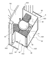
- FIG. 2 is a diagram showing the inside of the sound insulation unit of the outdoor unit according to the embodiment of the present invention.
- FIG. 3 is an exploded perspective view of the sound insulation unit of the outdoor unit according to the embodiment of the present invention.
- the sound insulation unit 6 has a side part 60 and an upper surface plate 64. In FIG. 2, the top plate 64 is omitted to clearly show the inside of the sound insulation unit 6.
- a compressor 4 is disposed inside the sound insulation unit 6.
- the side part 60 includes a front plate 61, a side plate 62, a back plate 63, and a bottom plate 65.
- the front plate 61, the side plate 62, the back plate 63, the top plate 64, and the bottom plate 65 are sheet metal.
- the bottom plate 65 is a rectangular tray-like member and is placed on the bottom panel 101 ⁇ / b> A of the housing 101. Edges extending upward are formed on the four sides of the bottom plate 65.
- the front plate 61 has a covering portion 611, a fixing portion 612, and a mounting portion 613. Due to the covering portion 611 and the fixing portion 612, the cross-sectional shape of the front plate 61 is L-shaped.
- the attachment portion 613 is formed on the side portion of the covering portion 611 opposite to the side portion on which the fixing portion 612 is formed, of the pair of side portions extending in the longitudinal direction.
- the front plate 61 is disposed on the front side of the outdoor unit 100 in the bottom panel 101 ⁇ / b> A of the housing 101.
- the side plate 62 has a covering portion 621 and a bent portion 622.
- the bent portion 622 is formed by bending one side portion of the pair of side portions extending in the longitudinal direction of the covering portion 621 at a right angle.
- the side plate 62 is disposed on the right side of the outdoor unit 100 in the bottom panel 101 ⁇ / b> A of the housing 101.
- a screw hole 622A is formed at the upper end of the bent portion 622.
- the back plate 63 has a covering portion 631, a fixing portion 632, and a bent portion 633. Due to the covering portion 631 and the fixing portion 632, the cross-sectional shape of the back plate 63 is L-shaped.
- the bent part 633 is formed by bending a side part opposite to the side part where the fixing part 632 is formed, of the pair of side parts extending in the longitudinal direction in the covering part 631 at a right angle. Yes. Further, the bent portion 633 is bent to the side opposite to the side where the fixing portion 632 is formed in the covering portion 631.
- the back plate 63 is disposed on the back side of the outdoor unit 100 in the bottom panel 101 ⁇ / b> A of the housing 101.
- the upper surface plate 64 has a covering portion 641, a locking portion 642, and extending portions 643 and 644. Due to the covering portion 641 and the locking portion 642, the cross-sectional shape of the upper surface plate 64 is L-shaped. An extension part 643 and an extension part 644 are formed on the side part opposite to the side part intersecting the covering part 641 in the locking part 642. The extending portion 643 is formed at the center of the upper surface plate 64 in the short direction. A screw hole 643A is formed in the extending portion 643. The extending portion 644 is formed on one end side of the both ends of the upper surface plate 64 in the short direction. A screw hole 644A is formed in the extending portion 644.
- the fixing portion 612 of the front plate 61 and the fixing portion 632 of the back plate 63 are fixed to the partition plate 102.
- the lower side portion of the covering portion 611 of the front plate 61 is fixed to the edge portion on the front surface side of the bottom plate 65.
- a lower side portion of the side plate 62 is fixed to an edge portion on the side surface side of the bottom plate 65.
- the lower side portion of the covering portion 631 of the back plate 63 is fixed to the back side edge of the bottom plate 65. That is, the front plate 61 and the back plate 63 are arranged to be parallel, and the side plate 62 is arranged to be parallel to the partition plate 102.
- the attachment portion 613 of the front plate 61 and the bent portion 622 of the side plate 62 are in contact with each other so that the attachment portion 613 is located on the front side of the bent portion 622.
- the vertical length of the attachment portion 613 is smaller than the vertical length of the bent portion 622, and the screw hole 622A of the bent portion 622 is exposed.
- the side portion where the bent portion 622 is not formed and the bent portion 633 of the back plate 63 are in contact.
- the bent portion 633 is located on the outer side with respect to the covering portion 621.
- the compressor 4 is placed on the bottom plate 65.
- the front side is covered with the covering portion 611 of the front plate 61
- the side surface side is covered with the covering portion 621 of the side plate 62
- the back side is covered with the covering portion 631 of the back plate 63.
- the side part 60 and the side part 60 of the compressor 4 face each other.
- the other side of the compressor 4 faces the partition plate 102.
- Anti-vibration cushions 51, 52 and 53 are elastic members.
- the anti-vibration cushions 51, 52, and 53 are members that are detachably attached in order to prevent excessive shaking of the compressor 4 when the outdoor unit 100 is transported to the installation location.
- the anti-vibration cushions 51 and 52 are disposed between the compressor 4 and the inner surface of the front plate 61 of the sound insulation unit 6.
- the anti-vibration cushion 53 is disposed between the compressor 4 and the inner surface of the back plate 63 of the sound insulation unit 6.
- Anti-vibration cushions 51 and 52 are mounted on a terminal block 41 provided on the upper portion of the outer surface of the compressor 4. Thereby, the position of the anti-vibration cushions 51 and 52 in the vertical direction is determined.
- the anti-vibration cushions 51 and 52 are sandwiched between the upper part of the inner surface of the front plate 61 of the sound insulation unit 6 and the upper part of the outer surface of the compressor 4.
- the anti-vibration cushion 53 is partially placed on the upper surface 42 of the compressor 4. Thereby, the position of the anti-vibration cushion 53 in the vertical direction is determined.
- the anti-vibration cushion 53 is sandwiched between the upper part of the inner surface of the back plate 63 of the sound insulation unit 6 and the upper part of the outer surface of the compressor 4.
- the vibration-proof cushions 51, 52, and 53 are sandwiched between the inner peripheral surface of the sound insulation unit 6 and the compressor 4.
- the vibration-proof cushions 51, 52, and 53 As described above, by arranging the vibration-proof cushions 51, 52, and 53, the vibration of the compressor 4 is suppressed when the outdoor unit 100 is transported. In addition, since the vibration-proof cushions 51, 52, and 53 are sandwiched between the sound insulation unit 6 and the compressor, they do not fall when the outdoor unit 100 is transported.
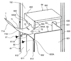
- FIG. 4 is an exploded perspective view showing the attachment structure of the warning notice for the compressor according to the embodiment of the present invention.
- the reminder 7 is made of synthetic paper having a predetermined strength that cannot be easily broken by the hand of the installation operator, and has a rectangular shape as a whole.
- the notice book 7 has a large portion 71 and a small width portion 72 having a width smaller than the large portion.
- a slit 73 is formed at the boundary between the large portion 71 and the narrow portion 72.
- a notch 74 is formed by the large portion 71 and the small width portion 72.
- On the surface 71 ⁇ / b> A of the large portion 71 a procedure for removing the above-described anti-vibration cushions 51, 52, and 53 is displayed.
- the removal procedure is displayed by combining character information (not shown) and image information. For example, the removal procedure is displayed as a character string, and an illustration is displayed below the character string.
- the small width portion 72 of the reminder 7 is positioned on the covering portion 641 side of the upper surface plate 64. Then, the extension portion 643 of the upper surface plate 64 is inserted into the slit 73 of the alerting note 7, and the side end portion of the extension portion 644 closer to the extending portion 643 is the notch 74 of the alerting note 7.
- the warning book 7 is attached to the upper surface plate 64 so as to be engaged with the corner.
- the upper surface plate 64 to which the warning book 7 is attached is disposed so as to cover the opening on the upper side of the front plate 61, the side plate 62, and the rear plate 63, that is, the opening of the side portion 60. .
- the upper surface plate 64 is disposed so that the locking portion 642 of the upper surface plate 64 is positioned in front of the covering portion 611 of the front surface plate 61. Then, the screw hole 643 ⁇ / b> A of the extending portion 643 of the upper surface plate 64 and the screw hole 611 ⁇ / b> A of the covering portion 611 of the front plate 61 are screwed with screws 81. Further, the screw hole 644A of the extending portion 644 of the upper surface plate 64 and the screw hole 622A of the bent portion 622 of the side surface plate 62 are screwed with screws 82.
- the upper surface plate 64 is attached, and the warning book 7 is attached so that the small width portion 72 is located inside the sound insulation unit 6 and the large portion 71 is located outside the sound insulation unit 6.
- the caution statement 7 is sandwiched between the upper surface plate 64 and the front plate 61, and the surface 71 ⁇ / b> A of the caution statement 7 faces the front plate 61 side of the sound insulation unit 6.
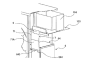
- FIG. 5 is a perspective view showing an example of an attached state of the warning notice for the compressor according to the embodiment of the present invention.
- the end opposite to the side where the narrow portion 72 is continuous is lifted upward, and is attached to the partition plate 103 by the adhesive tape 9. Yes. That is, a part of the reminder 7 is positioned in the vicinity of the electrical component box 104.
- the surface 71 ⁇ / b> A of the alert book 7 faces the front side of the outdoor unit 100.
- FIG. 6 is a perspective view showing an example of an attached state of the warning notice for the compressor according to the embodiment of the present invention.
- the reminder 7 hangs downward, and the end of the large portion 71 opposite to the side where the narrow portion 72 is continuous is adhered to the front of the sound insulation unit 6 by the adhesive tape 9. Affixed to the face plate 61. Therefore, the back surface 71 ⁇ / b> B of the reminder book 7 faces the front side of the outdoor unit 100.
- the procedure for removing the anti-vibration cushions 51, 52, and 53 is also displayed on the back surface 71B in the above-described manner.
- the outdoor unit 100 is provided with a warning book 7 on which a procedure for removing the vibration-proof cushions 51, 52, and 53 is displayed.
- the warning book 7 touches the eyes of the installation operator who installs the outdoor unit, the installation operator can be prevented from forgetting to remove the anti-vibration cushion.
- the warning book 7 is sandwiched between the top plate 64 and the front plate 61 screwed with screws 81 and 82. Furthermore, the extension part 643 of the upper surface plate 64 is inserted into the slit 73 of the reminder 7. Therefore, in order to remove the reminder 7, the screws 81 and 82 must be removed and the top plate 64 must be removed. By removing the top plate 64, the interior of the sound insulation unit 6 is exposed as shown in FIG. 2, and the vibration-proof cushions 51, 52, and 53 are in contact with the installation operator. As a result, there is an effect of urging the installation worker to remove the anti-vibration cushions 51, 52, and 53.
- the procedure for removing the anti-vibration cushions 51, 52, and 53 is displayed in combination with the character information and the image information. Therefore, the installation procedure can be intuitively understood by the installation operator.
- a part of the alert book 7 is positioned in the vicinity of the electrical component box 104.
- the electrical component box 104 is a member that is always checked by the installation operator in the installation work of the outdoor unit 100. Therefore, by sticking the alerting notice 7 as shown in FIG. 5, it can be easily touched by the installation operator, and the presence of the alerting notice 7 can be noticed by the installing operator.
- a part of the warning book 7 is affixed to the front plate 61 of the sound insulation unit 6, and the procedure for removing the anti-vibration cushion is displayed on both the front surface 71 ⁇ / b> A and the back surface 71 ⁇ / b> B.
- the sound insulation unit 6 is a member that is surely checked by the installation operator in the installation work of the outdoor unit 100. Therefore, by sticking the alerting note 7 as shown in FIG. 6, it can be easily touched by the installation operator, and the presence of the alerting note 7 can be noticed by the installer.
- the front plate 61, the side plate 62, the back plate 63, and the top plate 64 have different shapes as described above, and the assembly procedure is one. Therefore, when the sound insulation unit 6 is reassembled after the sound insulation unit 6 is disassembled for removing the warning book 7 and the anti-vibration cushions 51, 52, and 53, the installation operator easily performs the assembly work. be able to.
Landscapes
- Engineering & Computer Science (AREA)
- Chemical & Material Sciences (AREA)
- Combustion & Propulsion (AREA)
- Mechanical Engineering (AREA)
- General Engineering & Computer Science (AREA)
- Other Air-Conditioning Systems (AREA)
Abstract
防振クッション部品の取り忘れを防止する空気調和機の室外機を提供する。空気調和機の室外機は、筐体と、筐体の底面に配置された圧縮機と、遮音ユニットと、防振クッションとを有する。遮音ユニットは、圧縮機を覆うように配設され、圧縮機の動作時に発生する音が外部に伝わることを抑制する箱状の部材である。防振クッションは、遮音ユニットの内側面と前記圧縮機とで挟持され、室外機の運搬時における圧縮機の揺れを防止する部材である。室外機は、さらに、防振クッションの取り外し手順が表示されている注意喚起部材を備えている。
Description
本発明は、空気調和機の室外機に関するものであり、特に、室外機の運搬時における圧縮機の過度の揺れ対策として挿入する防振クッション部品の取り忘れ防止に関する。
従来、空気調和機の室外機を運搬する際、室外機の圧縮機が過度に揺れることを防止するための対策が講じられている。
例えば、特許文献1に記載の圧縮機には、下方周辺部における3箇所に径方向外側に突出する支持脚が設けられている。の運転中に防振支持するために、この支持脚が防振支持装置を介して底フレーム上に支持されている。一方、圧縮機の運搬中は、空気調和機の梱包に使用される運搬用パレットの上面に設けられた押上げ部により圧縮機を持ち上げ、これにより防振支持装置を働かない状態として固定している。そして、この固定状態を維持して圧縮機の移動を規制している。
しかしながら、特許文献1に記載の防振指示装置は、圧縮機の下方を支持するものであり、上部に発生する揺れを防止するようには構成されていない。そこで、圧縮機が搭載された室外機を運搬するとき、圧縮機の上部を防振クッション部品で抑えて、揺れを防止することが行われている。このような防振クッション部品は圧縮機を収納している遮音ユニットの内部に挿入される。そして、運搬後、室外機が据え付けられた後は、防振クッション部品は取り外される。しかしながら、防振クッション部品は遮音ユニットの内部に配設されており、据付作業者の目に触れることがないため、防振クッション部品の取り外しが行われない可能性がある。
本発明は、上記のような課題を解決するためになされたものであり、防振クッション部品の取り忘れを防止する空気調和機の室外機を提供することを目的とする。
本発明に係る空気調和機の室外機は、筐体と、筐体の底面に配置された圧縮機とを有する空気調和機の室外機であって、前記圧縮機を覆うように配設され、前記圧縮機の動作時に発生する音が外部に伝わることを抑制する箱状の遮音ユニットと、前記遮音ユニットの内側面と前記圧縮機とで挟持され、前記室外機の運搬時における前記圧縮機の揺れを防止する防振クッションと、前記防振クッションの取り外し手順が表示されている注意喚起部材とを備えているものである。
本発明に係る空気調和機の室外機によると、室外機を設置する据付作業者が防振クッションの取り外し作業を失念することを防止できる。
以下に、本発明における空気調和機の室外機の実施の形態を図面に基づいて詳細に説明する。尚、以下に説明する実施の形態によって本発明が限定されるものではない。また、以下の図面においては各構成部材の大きさは実際の装置とは異なる場合がある。
実施の形態.
図1は、本発明の実施の形態に係る空気調和機の室外機の斜視図である。室外機100の内部構造を明示するため、図1では一部の部材は省略され、若しくは切り欠いて示している。室外機100は筐体101を有している。筐体101の底面パネル101Aには仕切板102が設けられている。仕切板102により、筐体101の内部は風路室1と電気品室2及び機械室3とに区画されている。風路室1にはファン11が配設されている。ファン11は例えばプロペラファンであり、送風手段である。機械室3において底面パネル101Aには遮音ユニット6が配設されている。遮音ユニット6の内部には、後述する圧縮機が配設されている。また、筐体101の内部は仕切板103により電気品室2と機械室3に区画されており、電気品室2は機械室3の上部に設けられている。仕切板103には電気品が収納される電気品箱104が載置されている。
図1は、本発明の実施の形態に係る空気調和機の室外機の斜視図である。室外機100の内部構造を明示するため、図1では一部の部材は省略され、若しくは切り欠いて示している。室外機100は筐体101を有している。筐体101の底面パネル101Aには仕切板102が設けられている。仕切板102により、筐体101の内部は風路室1と電気品室2及び機械室3とに区画されている。風路室1にはファン11が配設されている。ファン11は例えばプロペラファンであり、送風手段である。機械室3において底面パネル101Aには遮音ユニット6が配設されている。遮音ユニット6の内部には、後述する圧縮機が配設されている。また、筐体101の内部は仕切板103により電気品室2と機械室3に区画されており、電気品室2は機械室3の上部に設けられている。仕切板103には電気品が収納される電気品箱104が載置されている。
注意喚起書7は、本発明の注意喚起部材である。注意喚起書7は、遮音ユニット6に取り付けられている。注意喚起書7には、防振クッションの取り外し手順が記載されている。注意喚起書7は、その一部が仕切板103に粘着テープ9により貼付されている。換言すると、注意喚起書7の一部は電気品室2の近傍に位置づけられている。尚、防振クッション及び注意喚起書7の詳細については後述する。
図2は、本発明の実施の形態に係る室外機の遮音ユニットの内部を示す図である。図3は、本発明の実施の形態に係る室外機の遮音ユニットの分解斜視図である。遮音ユニット6は、側方部60と上面板64とを有している。尚、図2においては、遮音ユニット6の内部を明示するため、上面板64は省略されている。遮音ユニット6の内部には、圧縮機4が配設されている。側方部60は、前面板61と、側面板62と、背面板63と、底面板65とを有している。前面板61、側面板62、背面板63、上面板64、及び底面板65は板金である。
底面板65は、矩形のトレー状の部材であり、筐体101の底面パネル101Aに載置されている。底面板65の4辺には上方に延びる縁部が形成されている。
前面板61は、被覆部611と固定部612と取付部613とを有している。被覆部611と固定部612により前面板61の断面形状はL字型を呈している。取付部613は、被覆部611において、長手方向に延びる一対の側辺部のうち固定部612が形成されている側辺部とは反対側の側辺部に形成されている。前面板61は、筐体101の底面パネル101Aにおいて、室外機100の前面側に配設されている。
側面板62は、被覆部621と折曲部622とを有している。折曲部622は、被覆部621の長手方向に延びる一対の側辺部のうち一方の側辺部を直角に曲げることにより形成されている。側面板62は、筐体101の底面パネル101Aにおいて、室外機100の右側面側に配設されている。折曲部622の上端にはネジ穴622Aが形成されている。
背面板63は、被覆部631と、固定部632と、折曲部633とを有している。被覆部631と固定部632により背面板63の断面形状はL字型を呈している。折曲部633は、被覆部631において、長手方向に延びる一対の側辺部のうち固定部632が形成されている側辺部とは反対側の側辺部を直角に曲げることにより形成されている。また、折曲部633は、被覆部631において固定部632が形成されている側とは反対側に折り曲げられている。背面板63は、筐体101の底面パネル101Aにおいて、室外機100の背面側に配設されている。
上面板64は、被覆部641と係止部642と延出部643及び644とを有している。被覆部641と係止部642により上面板64の断面形状はL字型を呈している。係止部642において被覆部641と交差する側辺部と反対側の側辺部に、延出部643と延出部644とが形成されている。延出部643は上面板64の短手方向の中央に形成されている。延出部643にはネジ穴643Aが形成されている。延出部644は上面板64の短手方向の両端部のうち一方の端部側に形成されている。延出部644にはネジ穴644Aが形成されている。
前面板61の固定部612及び背面板63の固定部632は、仕切板102に固定されている。前面板61の被覆部611の下辺部は、底面板65の前面側の縁部に固定されている。側面板62の下辺部は、底面板65の側面側の縁部に固定されている。背面板63の被覆部631の下辺部は、底面板65の背面側の縁部に固定されている。すなわち、前面板61と背面板63は平行となるよう配置され、側面板62は、仕切板102と平行となるよう配置されている。前面板61の取付部613と側面板62の折曲部622は、取付部613が折曲部622の前面側に位置するよう当接している。取付部613の上下方向の長さは折曲部622の上下方向の長さより小さく、折曲部622のネジ穴622Aは露出している。側面板62の被覆部621の長手方向に延びる一対の側辺部のうち折曲部622が形成されていない側辺部と、背面板63の折曲部633とが当接している。被覆部621に対して折曲部633が外方側に位置している。以上の構成により、前面板61、側面板62、及び背面板63の上辺部側、すなわち側方部60の上部には、矩形の開口部が形成されている。この開口部に上面板64が配設されている。
圧縮機4は、底面板65に載置されている。圧縮機4の側方において、前面側は前面板61の被覆部611で覆われ、側面側は側面板62の被覆部621で覆われ、背面側は背面板63の被覆部631で覆われている。換言すると、圧縮機4の側方の一部と側方部60は対向している。また、圧縮機4の側方の他の部分は仕切板102と対向している。
防振クッション51、52、及び53は弾力性を有する部材である。防振クッション51、52、及び53は、室外機100を設置場所へ運搬する際の圧縮機4の過度の揺れを防止するために着脱自在に取り付けられる部材である。防振クッション51及び52は、圧縮機4と遮音ユニット6の前面板61の内側面との間に配設されている。防振クッション53は、圧縮機4と遮音ユニット6の背面板63の内側面との間に配設されている。
防振クッション51及び52は、圧縮機4の外側面の上部に設けられた端子台41に載置されている。これにより、防振クッション51及び52の上下方向の位置は定められている。防振クッション51及び52は、遮音ユニット6の前面板61の内側面の上部と圧縮機4の外側面の上部とで挟持されている。防振クッション53は、圧縮機4の上面42に部分的に載置されている。これにより、防振クッション53の上下方向の位置は定められている。防振クッション53は、遮音ユニット6の背面板63の内側面の上部と圧縮機4の外側面の上部とで挟持されている。このように、防振クッション51、52、及び53は、遮音ユニット6の内周面と圧縮機4とで挟持されている。
以上のように、防振クッション51、52、及び53を配設することにより、室外機100の運搬時、圧縮機4の振動が抑制される。尚、防振クッション51、52、及び53は、遮音ユニット6と圧縮機と間で挟持されているため、室外機100の運搬時に落下することはない。
図4は、本発明の実施の形態に係る圧縮機の注意喚起書の取り付け構造を示す分解斜視図である。注意喚起書7は、据付作業者の手では容易に破ることができない程度の所定の強度を有する合成紙から成り、全体として矩形を呈している。注意喚起書7は、大幅部71と、大幅部より幅の小さい小幅部72とを有している。大幅部71と小幅部72との境界にはスリット73が形成されている。また、大幅部71と小幅部72により切欠き74が形成されている。大幅部71の表面71Aには、上述の防振クッション51、52、及び53を取り外す手順が表示されている。取り外しの手順は、図示省略の文字情報と画像情報とを組み合わせて表示されている。例えば、取り外しの手順を文字列で表示すると共に、当該文字列の下部にイラストが表示される。
ここで、上面板64及び注意喚起書7の取り付けについて説明する。注意喚起書7の小幅部72を上面板64の被覆部641側に位置づける。そして、注意喚起書7のスリット73に上面板64の延出部643を挿通させ、かつ、延出部644において延出部643に近い方の側端部が注意喚起書7の切欠き74のコーナーに係合するよう、注意喚起書7を上面板64に取り付ける。注意喚起書7が取り付けられている上面板64を、上述の前面板61、側面板62、及び背面板63の上辺部側の開口部、すなわち側方部60の開口部を覆うように配置する。このとき、上面板64の係止部642が前面板61の被覆部611よりも前側に位置するよう上面板64を配置する。そして、上面板64の延出部643のネジ穴643Aと前面板61の被覆部611のネジ穴611Aとをネジ81でネジ止めする。また、上面板64の延出部644のネジ穴644Aと側面板62の折曲部622のネジ穴622Aとをネジ82でネジ止めする。これにより、上面板64が取り付けられると共に、注意喚起書7が、小幅部72が遮音ユニット6の内部に位置し、大幅部71が遮音ユニット6の外部に位置するよう取り付けられる。この状態で、注意喚起書7は、上面板64と前面板61との間に挟み込まれており、注意喚起書7の表面71Aは、遮音ユニット6の前面板61側を向いている。
図5は、本発明の実施の形態に係る圧縮機の注意喚起書の取り付け状態の一例を示す斜視図である。図5に示すように、注意喚起書7の大幅部71において、小幅部72が連続している側と反対側の端部が上方に持ち上げられ、粘着テープ9により仕切板103に貼り付けられている。すなわち、注意喚起書7の一部が電気品箱104の近傍に位置づけられている。これにより、注意喚起書7の表面71Aが室外機100の前面側を向いている。
図6は、本発明の実施の形態に係る圧縮機の注意喚起書の取り付け状態の一例を示す斜視図である。図6に示すように、注意喚起書7は下方向に垂れており、大幅部71において小幅部72が連続している側と反対側の端部は、粘着テープ9により、遮音ユニット6の前面板61に貼り付けられている。従って、注意喚起書7の裏面71Bが室外機100の前面側を向いている。この例においては、裏面71Bにも、防振クッション51、52、及び53を取り外す手順が上述した態様で表示されている。
本実施の形態によれば、室外機100は、防振クッション51、52、及び53を取り外す手順が表示されている注意喚起書7を備えている。注意喚起書7が室外機を設置する据付作業者の目に触れることにより、据付作業者が防振クッションの取り外し作業を失念することを防止できる。
注意喚起書7は、ネジ81及び82でネジ止めされた上面板64と前面板61との間に挟み込まれている。さらに、注意喚起書7のスリット73には上面板64の延出部643が挿入されている。従って、注意喚起書7を除去するためには、ネジ81及び82を外し、上面板64を取り外さなければならない。上面板64を取り外すことにより、図2に示すように遮音ユニット6の内部が露出し、防振クッション51、52、及び53が据付作業者の目に触れることとなる。その結果、防振クッション51、52、及び53の取り外し作業を据付作業者に促す効果がある。
本実施の形態によれば、防振クッション51、52、及び53の取り外し作業の手順を文字情報と画像情報とを組み合わせて表示している。従って、当該作業手順を据付作業者に視覚により直感的に理解させることができる。
図5に示す例では、注意喚起書7の一部が電気品箱104の近傍に位置づけられている。電気品箱104は、室外機100の据え付け作業において据付作業者が必ずチェックする部材である。従って、注意喚起書7を図5のように貼付することで、据付作業者の目に触れやすくすることができ、注意喚起書7の存在を据付作業者に気付かせることができる。
図6に示す例では、注意喚起書7の一部が遮音ユニット6の前面板61に貼り付けられており、表面71A及び裏面71Bの双方に防振クッションの取り外し作業の手順が表示されている。遮音ユニット6は、室外機100の据え付け作業において据付作業者が必ずチェックする部材である。従って、注意喚起書7を図6のように貼付することにより、据付作業者の目に触れやすくすることができ、注意喚起書7の存在を据付作業者に気付かせることができる。
前面板61、側面板62、背面板63、及び上面板64は、上述のようにそれぞれの形状が異なっており、組立の手順は一通りである。従って、注意喚起書7の取り外し、並びに防振クッション51、52、及び53の取り外しのために遮音ユニット6を解体した後、再び遮音ユニット6を組み立てるとき、据付作業者は容易に組立作業を行うことができる。
1 風路室、2 電気品室、3 機械室、4 圧縮機、6 遮音ユニット、7 注意喚起書、9 粘着テープ、11 ファン、41 端子台、42 上面、51 防振クッション、52 防振クッション、53 防振クッション、60 側方部、61 前面板、62 側面板、63 背面板、64 上面板、65 底面板、71 大幅部、71A 表面、71B 裏面、72 小幅部、73 スリット、74 切欠き、81 ネジ、82 ネジ、100 室外機、101 筐体、101A 底面パネル、102 仕切板、103 仕切板、104 電気品箱、611 被覆部、611A ネジ穴、612 固定部、613 取付部、621 被覆部、622 折曲部、622A ネジ穴、631 被覆部、632 固定部、633 折曲部、641 被覆部、642 係止部、643 延出部、643A ネジ穴、644 延出部、644A ネジ穴。
Claims (7)
- 筐体と、筐体の底面に配置された圧縮機とを有する空気調和機の室外機であって、
前記圧縮機を覆うように配設され、前記圧縮機の動作時に発生する音が外部に伝わることを抑制する箱状の遮音ユニットと、
前記遮音ユニットの内側面と前記圧縮機とで挟持され、前記室外機の運搬時における前記圧縮機の揺れを防止する防振クッションと、
前記防振クッションの取り外し手順が表示されている注意喚起部材とを備えている空気調和機の室外機。 - 前記遮音ユニットは、
前記圧縮機の側方の一部に対向し、上部に開口部が形成されている側方部と、
前記開口部を覆う上面板とを有し、
前記注意喚起部材は、前記取り外し手順が表示された部分が前記遮音ユニットの外方に位置づけられるよう、前記上面板と前記側方部との間に挟み込まれている
請求項1に記載の空気調和機の室外機。 - 前記側方部は、前記室外機の前面側に配設されている前面板と、前記室外機の側面側に配設されている側面板と、前記室外機の背面側に配設されている背面板とを有しており、
前記上面板と前記前面板はネジ止めされており、
前記注意喚起部材は、前記前面板と前記上面板との間に挟みこまれている請求項2に記載の空気調和機の室外機。 - 前記注意喚起部材の一部は、前記室外機に配設されている電気品箱の近傍に位置づけられている請求項1~3のいずれか一項に記載の空気調和機の室外機。
- 前記注意喚起部材は、所定の強度を有する合成紙である請求項1~4のいずれか一項に記載の空気調和機の室外機。
- 前記取り外し手順は、文字情報と画像情報とを組み合わせて表示されている請求項1~5のいずれか一項に記載の空気調和機の室外機。
- 前記取り外し手順は、前記合成紙の表面及び裏面の少なくとも一方に表示されている請求項5に記載の空気調和機の室外機。
Priority Applications (4)
| Application Number | Priority Date | Filing Date | Title |
|---|---|---|---|
| EP17905052.1A EP3611436B1 (en) | 2017-04-11 | 2017-04-11 | Outdoor unit of air conditioner |
| JP2019512085A JP6762421B2 (ja) | 2017-04-11 | 2017-04-11 | 空気調和機の室外機 |
| CN201790000598.1U CN209026961U (zh) | 2017-04-11 | 2017-04-11 | 空调机的室外机 |
| PCT/JP2017/014829 WO2018189811A1 (ja) | 2017-04-11 | 2017-04-11 | 空気調和機の室外機 |
Applications Claiming Priority (1)
| Application Number | Priority Date | Filing Date | Title |
|---|---|---|---|
| PCT/JP2017/014829 WO2018189811A1 (ja) | 2017-04-11 | 2017-04-11 | 空気調和機の室外機 |
Publications (1)
| Publication Number | Publication Date |
|---|---|
| WO2018189811A1 true WO2018189811A1 (ja) | 2018-10-18 |
Family
ID=63793310
Family Applications (1)
| Application Number | Title | Priority Date | Filing Date |
|---|---|---|---|
| PCT/JP2017/014829 WO2018189811A1 (ja) | 2017-04-11 | 2017-04-11 | 空気調和機の室外機 |
Country Status (4)
| Country | Link |
|---|---|
| EP (1) | EP3611436B1 (ja) |
| JP (1) | JP6762421B2 (ja) |
| CN (1) | CN209026961U (ja) |
| WO (1) | WO2018189811A1 (ja) |
Citations (7)
| Publication number | Priority date | Publication date | Assignee | Title |
|---|---|---|---|---|
| JPH04184025A (ja) * | 1990-11-15 | 1992-07-01 | Matsushita Electric Ind Co Ltd | 空気調和機 |
| JPH07208771A (ja) * | 1994-01-14 | 1995-08-11 | Toshiba Corp | 空気調和機の室外機 |
| JP2003323665A (ja) * | 2002-04-30 | 2003-11-14 | N & S:Kk | 自動販売機用のダミー体 |
| JP2009014228A (ja) * | 2007-07-03 | 2009-01-22 | Daikin Ind Ltd | 冷凍装置 |
| JP3165835U (ja) * | 2010-10-12 | 2011-02-10 | 株式会社渡辺塗装 | エアコン室外機養生カバー |
| JP2014213873A (ja) | 2013-04-24 | 2014-11-17 | ダイキン工業株式会社 | 空気調和機における圧縮機の支持構造 |
| JP2015161477A (ja) * | 2014-02-28 | 2015-09-07 | シャープ株式会社 | 空気調和機、レシーバタンク、および空気調和機における提供サービス確認方法 |
Family Cites Families (4)
| Publication number | Priority date | Publication date | Assignee | Title |
|---|---|---|---|---|
| JP2013148236A (ja) * | 2012-01-17 | 2013-08-01 | Sharp Corp | 空気調和機の室外機、その他の防振装置付きの圧縮機を搭載した機器 |
| CN203797824U (zh) * | 2014-04-24 | 2014-08-27 | 珠海格力电器股份有限公司 | 减振安装结构及具有其的压缩机 |
| CN205332406U (zh) * | 2015-12-25 | 2016-06-22 | 广东美的制冷设备有限公司 | 压缩机组件、室外机及空调器 |
| CN106440102A (zh) * | 2016-11-28 | 2017-02-22 | 广东欧科空调制冷有限公司 | 吊顶式空调外机的压缩机减振结构 |
-
2017
- 2017-04-11 CN CN201790000598.1U patent/CN209026961U/zh active Active
- 2017-04-11 EP EP17905052.1A patent/EP3611436B1/en active Active
- 2017-04-11 WO PCT/JP2017/014829 patent/WO2018189811A1/ja unknown
- 2017-04-11 JP JP2019512085A patent/JP6762421B2/ja active Active
Patent Citations (7)
| Publication number | Priority date | Publication date | Assignee | Title |
|---|---|---|---|---|
| JPH04184025A (ja) * | 1990-11-15 | 1992-07-01 | Matsushita Electric Ind Co Ltd | 空気調和機 |
| JPH07208771A (ja) * | 1994-01-14 | 1995-08-11 | Toshiba Corp | 空気調和機の室外機 |
| JP2003323665A (ja) * | 2002-04-30 | 2003-11-14 | N & S:Kk | 自動販売機用のダミー体 |
| JP2009014228A (ja) * | 2007-07-03 | 2009-01-22 | Daikin Ind Ltd | 冷凍装置 |
| JP3165835U (ja) * | 2010-10-12 | 2011-02-10 | 株式会社渡辺塗装 | エアコン室外機養生カバー |
| JP2014213873A (ja) | 2013-04-24 | 2014-11-17 | ダイキン工業株式会社 | 空気調和機における圧縮機の支持構造 |
| JP2015161477A (ja) * | 2014-02-28 | 2015-09-07 | シャープ株式会社 | 空気調和機、レシーバタンク、および空気調和機における提供サービス確認方法 |
Non-Patent Citations (1)
| Title |
|---|
| See also references of EP3611436A4 |
Also Published As
| Publication number | Publication date |
|---|---|
| EP3611436B1 (en) | 2021-07-21 |
| EP3611436A1 (en) | 2020-02-19 |
| CN209026961U (zh) | 2019-06-25 |
| JP6762421B2 (ja) | 2020-09-30 |
| JPWO2018189811A1 (ja) | 2019-12-12 |
| EP3611436A4 (en) | 2020-04-01 |
Similar Documents
| Publication | Publication Date | Title |
|---|---|---|
| JP2013148236A (ja) | 空気調和機の室外機、その他の防振装置付きの圧縮機を搭載した機器 | |
| WO2018189811A1 (ja) | 空気調和機の室外機 | |
| JP2015193398A (ja) | 空気調和機の梱包装置及び空気調和機 | |
| JPH10270879A (ja) | 電子機器の冷却構造 | |
| CN110999051A (zh) | 电力变换装置及排气用构造体 | |
| JP2015072724A (ja) | 情報処理装置 | |
| JP2017157656A (ja) | 電子機器の筐体構造 | |
| JP5517896B2 (ja) | エレベータ制御盤 | |
| US10480536B2 (en) | Fan unit fixing structure and electronic equipment | |
| JP6603524B2 (ja) | 警報器 | |
| JP6606895B2 (ja) | 電子機器、電子機器ユニットおよびディスプレイ | |
| JP4427301B2 (ja) | ノート型のポータブルコンピュータ | |
| JP5968582B2 (ja) | 室外機および室外機の組立方法 | |
| JP2007109707A (ja) | 電気機器 | |
| JP2020161611A (ja) | 電子機器 | |
| JP7345967B2 (ja) | 電気機器収納用箱 | |
| JP4843331B2 (ja) | 電気部品の取付構造 | |
| JP2008102800A (ja) | 電気機器 | |
| JP6564211B2 (ja) | 取り付け具、取り付けシステムおよび電気機器の筐体 | |
| JP2023101054A (ja) | ケースおよび分電盤 | |
| JP4900273B2 (ja) | 電装品ユニット | |
| JP6660128B2 (ja) | 警報器 | |
| JP5335106B2 (ja) | 送風装置 | |
| JP2010056449A (ja) | 製品分解時の部品保護構造 | |
| JP2018011237A (ja) | 吹鳴装置 |
Legal Events
| Date | Code | Title | Description |
|---|---|---|---|
| 121 | Ep: the epo has been informed by wipo that ep was designated in this application |
Ref document number: 17905052 Country of ref document: EP Kind code of ref document: A1 |
|
| ENP | Entry into the national phase |
Ref document number: 2019512085 Country of ref document: JP Kind code of ref document: A |
|
| NENP | Non-entry into the national phase |
Ref country code: DE |
|
| ENP | Entry into the national phase |
Ref document number: 2017905052 Country of ref document: EP Effective date: 20191111 |