WO2018179759A1 - ハウジングとそれを用いた回転電機及び回転電機のハウジングの製造方法 - Google Patents
ハウジングとそれを用いた回転電機及び回転電機のハウジングの製造方法 Download PDFInfo
- Publication number
- WO2018179759A1 WO2018179759A1 PCT/JP2018/002309 JP2018002309W WO2018179759A1 WO 2018179759 A1 WO2018179759 A1 WO 2018179759A1 JP 2018002309 W JP2018002309 W JP 2018002309W WO 2018179759 A1 WO2018179759 A1 WO 2018179759A1
- Authority
- WO
- WIPO (PCT)
- Prior art keywords
- housing
- tab
- support member
- main body
- rotating electrical
- Prior art date
- Legal status (The legal status is an assumption and is not a legal conclusion. Google has not performed a legal analysis and makes no representation as to the accuracy of the status listed.)
- Ceased
Links
Images



Classifications
-
- H—ELECTRICITY
- H02—GENERATION; CONVERSION OR DISTRIBUTION OF ELECTRIC POWER
- H02K—DYNAMO-ELECTRIC MACHINES
- H02K1/00—Details of the magnetic circuit
- H02K1/06—Details of the magnetic circuit characterised by the shape, form or construction
- H02K1/12—Stationary parts of the magnetic circuit
- H02K1/18—Means for mounting or fastening magnetic stationary parts on to, or to, the stator structures
- H02K1/185—Means for mounting or fastening magnetic stationary parts on to, or to, the stator structures to outer stators
-
- H—ELECTRICITY
- H02—GENERATION; CONVERSION OR DISTRIBUTION OF ELECTRIC POWER
- H02K—DYNAMO-ELECTRIC MACHINES
- H02K15/00—Processes or apparatus specially adapted for manufacturing, assembling, maintaining or repairing of dynamo-electric machines
- H02K15/02—Processes or apparatus specially adapted for manufacturing, assembling, maintaining or repairing of dynamo-electric machines of stator or rotor bodies
- H02K15/028—Fastening stator or rotor bodies to casings, supports, shafts or hubs
-
- H—ELECTRICITY
- H02—GENERATION; CONVERSION OR DISTRIBUTION OF ELECTRIC POWER
- H02K—DYNAMO-ELECTRIC MACHINES
- H02K15/00—Processes or apparatus specially adapted for manufacturing, assembling, maintaining or repairing of dynamo-electric machines
- H02K15/14—Casings; Enclosures; Supports
-
- H—ELECTRICITY
- H02—GENERATION; CONVERSION OR DISTRIBUTION OF ELECTRIC POWER
- H02K—DYNAMO-ELECTRIC MACHINES
- H02K5/00—Casings; Enclosures; Supports
Definitions
- the present invention relates to a housing, a rotating electrical machine using the housing, and a method for manufacturing the housing of the rotating electrical machine.
- a first tab having only a bolt hole and a second tab having both a bolt hole and a dowel pin knock hole are provided (patented) Reference 1).
- Patent Document 1 Although the technique described in Patent Document 1 is clamped and fixed with bolts after positioning with dowel pins, it describes a problem related to a decrease in mounting accuracy and positioning accuracy due to variations in formation of the first tab and the second tab. It has not been.
- An object of the present invention is to improve the reliability of a rotating electric machine while assembling a housing with a mating bracket with high accuracy.
- a housing for a rotating electrical machine is a housing for a rotating electrical machine that houses a stator of the rotating electrical machine and is supported by a support member, and includes a first tab that forms a first through hole that penetrates a first screw; A second tab that forms a second through hole that penetrates the second screw and that forms a fitting portion that fits with the position adjustment member, and the first tab is connected to the support member of the first tab.
- the first facing surface is formed farther from the support member than the second facing surface of the second tab with the support member.
- the housing can be assembled to the mating bracket with high accuracy and the reliability of the rotating electrical machine can be improved.
- FIG. 1 is an external perspective view of a rotating electrical machine 100 according to the present embodiment.
- 7 is a schematic side view showing a state in which a housing 400 according to a comparative example is fixed to a support member 500.
- FIG. It is a perspective view which shows the 1st process of the manufacturing method of the housing 400 which concerns on a comparative example.
- It is a side view which shows the 2nd process of the manufacturing method of the housing 400 which concerns on a comparative example.
- FIG. 6 is a schematic side view showing a state in which a housing 400 is fixed to a support member 500 by the manufacturing method according to the present embodiment.
- FIG. 7 is an enlarged view around a first tab 410 shown in FIG. 6.
- FIG. 1 is an exploded perspective view of a rotating electrical machine 100 according to the present embodiment.
- the rotating electrical machine 100 is composed of a rotor 200, a stator 300, and a housing 400.
- high output is required for automobiles, generators or drive motors, and the rotating electrical machines are also enlarged with the high output.
- the rotor 200 includes a plurality of rotor iron cores and permanent magnets.
- the plurality of rotor cores are arranged in the direction of the rotation axis and are skewed with respect to each other.
- the stator 300 is formed of a divided core and a coil wound around the core.
- the outer periphery of the stator 300 is fixed to the inner periphery of the housing 400 by shrink fitting.
- the housing 400 is thicker in order to withstand vibrations caused by the vehicle as the rotating electrical machine 100 becomes larger.
- the housing 400 is manufactured by drawing to improve productivity.
- the plate thickness increases, manufacturing by drawing has become difficult.
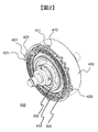
- FIG. 2 is an external perspective view of the rotating electrical machine 100 according to the present embodiment.
- the housing 400 includes two first tabs 410 facing each other with the rotor 200 interposed therebetween, and two second tabs 420 facing each other with the rotor 200 interposed therebetween.
- Each of the two first tabs 410 forms a first through hole 411 that penetrates a first screw 601 described later.
- Each of the two second tabs 420 forms a second through hole 421 that penetrates the second screw 602 and a fitting portion 422 that fits with the position adjusting member 701.
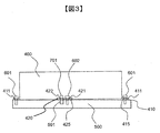
- FIG. 3 is a schematic side view showing a state in which the housing 400 according to the comparative example is fixed to the support member 500.
- the housing 400 is supported with respect to the support member 500 by the first screw 601 and the second screw 602. Positioning of the housing 400 and the support member 500 is performed by a position adjustment member 701.
- the support member 500 forms a fitting portion 501 that fits with the position adjustment member 701.
- the position adjustment member 701 is also called a dowel pin.
- the first tab 410 has a first facing surface 415 with the support member 500
- the second tab 420 has a second facing surface 425 with the support member 500.
- the first tab 410 of the housing 400 according to the comparative example is formed such that the first facing surface 415 is closer to the support member 500 than the edge of the housing 400 and the second facing surface 425 are closer.
- the first facing surface 415 of the first tab 410 contacts the support member 500, and the housing 400 is inclined. Then, the second facing surface 425 is inclined with respect to the support member 500. In such a state, the housing 400 and the support member 500 are positioned by the position adjustment member 701 in the fitting portion 422 of the second tab 420 and the fitting portion 501 of the support member 500.
- the fitting portion 422 is inclined with respect to the support member 500, and the position adjusting member 701 cannot be fitted with the fitting portion 422, making positioning difficult. There was a problem.
- the position adjustment member 701 can be fitted by increasing the hole diameter of the fitting portion 422 of the second tab 420 so that the second tab 420 can be fitted even when tilted.
- another problem that the positioning accuracy deteriorates occurs.
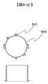
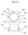
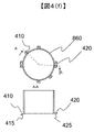
- 4 (a) to 4 (f) show a method for manufacturing the housing 400 according to the comparative example.
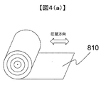
- the housing 400 is manufactured through a drawing process from the roll material rolled in the order of FIGS. 4A to 4F in order to improve productivity.
- the roll material 810 is finished to a predetermined size by passing a plate-like material between a plurality of rotating rolls.
- the blank material 820 is punched into a predetermined shape by pressing the roll material 810.
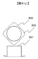
- the drawing material 830 is processed into a pot shape by blanking the blank material 820.
- the trimming material 840 has a substantially cylindrical shape by trimming the bottom portion 831 and the outer peripheral portion 832 of the drawing material 830.
- the tab flattening process material 850 is flattened by press-molding the tab intermediate member 841 with the first jig 851 and the second jig 852.
- the final housing shape 860 is completed by flattening through a tab flattening step.
- the tab flattening process material 850 shown in FIG. 4E has a different spring back as shown in the final housing shape 860 even if all the tabs are pressed under the same conditions, and the first facing surface 415. And the distance between the support member 500 and the distance between the second facing surface 425 and the support member 500 are different. It is difficult to make the distances the same, and there is a risk of manufacturing variations as shown in FIG.
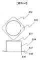
- FIG. 5A is a bottom view and a cross-sectional view showing a third step of the method for manufacturing the housing 400 according to the present embodiment.
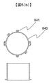
- FIG. 5B is a bottom view and a cross-sectional view showing a fourth step of the method for manufacturing the housing 400 according to the present embodiment.
- the drawing material 830 is processed into a cylindrical shape by drawing the blank material 820.
- the connection portion 836 connecting the main body portion 834 and the flange portion 835 corresponding to the first tab 410 and the second tab 420 formed later is separated from the support member 500 along the direction toward the distal end 837 of the main body portion. The distance is increased.
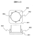
- the tab flattening process material 850 is formed by pressing the tab intermediate member 841 with the first jig 851 and the second jig 852, and at this time, the second tab 420 is flattened. Only flatten out.
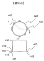
- the final housing shape 860 is completed by flattening through a tab flattening process. Since the first tab 410 is not flattened, the first tab 410 is formed such that the distance away from the support member 400 is increased along the direction from the connection portion 441 to the tip 452 of the main body portion 430. Accordingly, the first facing surface 415 can be formed farther from the support member 500 than the second facing surface 425.
- FIG. 6 is a schematic side view showing a state where the housing 400 is fixed to the support member 500 by the manufacturing method according to the present embodiment.
- the first facing surface 415 of the first tab 410 with the supporting member 500 is formed farther from the supporting member 500 than the second facing surface 425 of the second tab 420 with the supporting member 500.
- the second facing surface 425 can be substantially parallel to the support member 500, and the position adjustment member 701 and the fitting portion 422 can be fitted without the need to increase the hole diameter of the fitting portion 422.
- positioning accuracy can be improved.
- the first tab 410 can be bent and assembled by tightening the first screw 601, and the reliability against vibration of the vehicle can be improved.
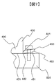
- FIG. 7 is an enlarged view around the first tab 410 shown in FIG.
- a main body part 430 that forms a housing space of the housing 400, a connection part 441 that connects the first tab 410, a first tab main body part 450 that forms a first through hole 411, Consists of.
- the first tab main body 450 forms a surface 451 that forms a flush surface 442 with the edge 431 of the main body 430 of the housing 400.
- the first tab main body 450 is formed such that the distance away from the support member 500 increases along the direction from the connection portion 441 to the tip 452 of the first tab main body 450.
- drawing material 831 ... bottom part, 832 ... outer peripheral part, 834 ... main body part, 835 ... collar part, 836 ... connection part, 837 ... tip, 840 ... trimming material, 841 ... tab intermediate material, 850 ... tab flattening process material, 851 ... first jig, 852 ... second jig, 860 ... final housing shape
Landscapes
- Engineering & Computer Science (AREA)
- Power Engineering (AREA)
- Manufacturing & Machinery (AREA)
- Manufacture Of Motors, Generators (AREA)
- Motor Or Generator Frames (AREA)
Abstract
ハウジングを精度良く相手側ブラケットに組付ける共に、回転電機の信頼性を向上することを目的とする。本発明に係る回転電機のハウジングは、回転電機のステータを収納するとともに支持部材により支持される回転電機のハウジングであって、第1ネジを貫通する第1貫通孔を形成する第1タブと、第2ネジを貫通する第2貫通孔を形成するとともに位置調整部材と嵌め合う嵌合部を形成する第2タブと、を備え、前記第1タブは、当該第1タブの前記支持部材との第1対向面が前記第2タブの当該支持部材との第2対向面よりも当該支持部材から離れて形成される。
Description
本発明は、ハウジングとそれを用いた回転電機及び回転電機のハウジングの製造方法に関する。
自動車用、発電機又は駆動用モータは高出力化が求められており、高出力に伴い、回転電機も大型化されている。これにより回転電機を支持部材に固定する場合の信頼性の向上が重要になってきている。
例えばステータコアを勘合したハウジングに固定する際、ボルトの通孔のみを形成した第1タブと、ボルト通孔とダウエルピンのためのノック孔の両方を形成する第2タブと、を設けている(特許文献1)。
しかしながら、特許文献1に記載の技術は、ダウエルピンによる位置決めを行った後ボルトにより締め付け固定されるが、第1タブと第2タブの形成時のバラつきにより取り付け精度や位置決め精度の低下に関する課題について記載されていない。
本発明の課題は、ハウジングを精度良く相手側ブラケットに組付ける共に、回転電機の信頼性を向上することである。
本発明に係る回転電機のハウジングは、回転電機のステータを収納するとともに支持部材により支持される回転電機のハウジングであって、第1ネジを貫通する第1貫通孔を形成する第1タブと、第2ネジを貫通する第2貫通孔を形成するとともに位置調整部材と嵌め合う嵌合部を形成する第2タブと、を備え、前記第1タブは、当該第1タブの前記支持部材との第1対向面が前記第2タブの当該支持部材との第2対向面よりも当該支持部材から離れて形成される。
本発明により、ハウジングを精度良く相手側ブラケットに組付ける共に、回転電機の信頼性を向上させることができる。
以下、図面を用いて本発明の実施例を説明する。
図1は、本実施形態に係る回転電機100の分解斜視図である。
回転電機100は、ロータ200とステータ300とハウジング400により構成されている。特に自動車用、発電機又は駆動用モータは高出力化が求められており、高出力に伴い、回転電機も大型化されている。
ロータ200は、複数のロータ鉄心と、永久磁石とにより構成される。複数のロータ鉄心は、回転軸方向に並べられ、互いにスキューされている。
ステータ300は、分割したコアで形成され、このコアに巻回したコイルと、により構成される。ステータ300は、その外周がハウジング400の内周と焼嵌めにより固定される。
ハウジング400は、回転電機100の大型化と伴い、車両による振動に耐えるため、板厚が厚くなっている。一方、ハウジング400は生産性向上のため、絞り加工により製作されるが、板厚の厚肉化に伴い、絞り加工による製作は難しくなってきている。
図2は、本実施形態に係る回転電機100の外観斜視図である。
ハウジング400は、ロータ200を介して互いに対向する2つの第1タブ410と、ロータ200を介して互いに対向する2つの第2タブ420と、を備える。2つの第1タブ410のそれぞれは、後述する第1ネジ601を貫通する第1貫通孔411を形成する。2つの第2タブ420のそれぞれは、第2ネジ602を貫通する第2貫通孔421と、位置調整部材701と嵌め合う嵌合部422と、を形成する。
図3は、比較例に係るハウジング400が支持部材500に固定されている状態を表す側面概略図である。
ハウジング400は、第1ネジ601及び第2ネジ602により支持部材500に対して支持される。ハウジング400と支持部材500との位置決めは、位置調整部材701により為される。支持部材500は、位置調整部材701と嵌め合う嵌合部501を形成する。位置調整部材701は、ダウエルピンとも呼ばれる。
第1タブ410は支持部材500との第1対向面415を有し、第2タブ420は支持部材500との第2対向面425を有する。比較例に係るハウジング400の第1タブ410は、第1対向面415がハウジング400の縁部や第2対向面425がよりも支持部材500に近づくように形成される。
この場合、第1タブ410の第1対向面415が支持部材500に接触し、ハウジング400が傾いた状態となる。そして、第2対向面425は支持部材500に対して傾いた状態となる。このような状態で、ハウジング400と支持部材500は、第2タブ420の嵌合部422と支持部材500の嵌合部501が位置調整部材701によって位置決めされる。
第2対向面425が支持部材500に対して傾くと、支持部材500に対して嵌合部422が傾いてしまい、位置調整部材701が嵌合部422と嵌合できず、位置決めが困難になるという課題があった。または、第2タブ420が傾いても嵌合できるように、第2タブ420の嵌合部422の穴径を大きくして、位置調整部材701を嵌合できるようにすることもできる。しかしこの場合、位置決め精度が悪化するという別な課題が発生する。
図4(a)ないし図4(f)は、比較例に係るハウジング400の製造方法である。
ハウジング400を製作する際、生産性向上のため、図4(a)から図4(f)の順で圧延されたロール材より絞り工程を経てハウジング400は製作される。
図4(a)に示されるように、ロール材810は、回転する複数のロールの間に板状の材料を通し、所定の寸法に仕上げ製作される。
図4(b)に示されるように、ブランク材820は、ロール材810を所定の形状にプレスによって打ち抜き加工される。
図4(c)及び図4(d)に示されるように、絞り材830は、ブランク材820を絞りによりお釜形状に加工される。トリミング材840は、絞り材830の底辺部831及び外周部832をトリミングにより略筒形状となる。
図4(d)及び図4(e)に示されるように、タブ平面出し工程材850は、タブ中間材841を第1ジグ851と第2ジグ852によりプレス成型され平面出しされる。
図4(f)に示されるように、ハウジング最終形状860は、タブ平面出し工程を経て平面出しが行われ完成したものである。
図4(a)ないし図4(f)に示される圧延材は、圧延方向及び圧延方向に対して角度を持った方向(例えば45°方向、90°方向)で性質が異なることが知られている。この異方性の現象は、曲げ後のスプリングバック量にも影響を及ぼす。
このため、図4(e)に示されたタブ平面出し工程材850は、すべてのタブを同じ条件でプレスしても、ハウジング最終形状860に示すようにスプリングバックが異なり、第1対向面415と支持部材500の距離及び第2対向面425と支持部材500との距離が異なってしまう。この距離を同一にすることは困難であり、図3に示されるような製造のバラツキを生じてしまうおそれがある。
そこで本実施形態に係るハウジングの製造方法を以下に説明する。
図4(a)及び図4(b)に示される工程は比較例の工程と同じである。図5(a)は、本実施形態に係るハウジング400の製造方法の第3工程を示す下面図及び断面図である。図5(b)は、本実施形態に係るハウジング400の製造方法の第4工程を示す下面図及び断面図である。
絞り材830は、ブランク材820を絞りにより筒型形状に加工される。この際、本体部834と後に形成される第1タブ410及び第2タブ420に相当するツバ部835を接続する接続部836から、本体部の先端837への方向に沿って支持部材500から離れる距離が大きくなるように形成する。
図5(c)に示されるように、タブ平面出し工程材850は、タブ中間材841を第1ジグ851と第2ジグ852によりプレス成型され平面出しされるが、このとき、第2タブ420のみ平面出しを行う。
図5(d)に示されるように、ハウジング最終形状860は、タブ平面出し工程を経て平面出しが行われ完成したものである。第1タブ410は、平面出しを行っていないため、接続部441から本体部430の先端452への方向に沿って支持部材400から離れる距離が大きくなるように形成される。これにより、第1対向面415が、第2対向面425よりも支持部材500から離れて形成させることが出来る。
図6は、本実施形態に係る製造方法によるハウジング400が支持部材500に固定されている状態を表す側面概略図である。
第1タブ410における支持部材500との第1対向面415が、第2タブ420における支持部材500との第2対向面425よりも支持部材500から離れて形成される。これにより、第2対向面425は支持部材500に対して略平行とすることができ、嵌合部422の穴径を大きくする必要はなく位置調整部材701と嵌合部422を嵌合が可能であり、位置決め精度を向上することができる。
また、ハウジング400を支持部材500に位置決めした後、第1ネジ601の締め付けにより第1タブ410を撓ませて組み付けることができ、車両の振動に対する信頼性を向上することができる。
図7は、図6に示された第1タブ410周辺の拡大図である。
ハウジング400の第1タブ410周辺は、ハウジング400の収納空間を形成する本体部430と第1タブ410を接続する接続部441と、第1貫通孔411を形成する第1タブ本体部450と、によって構成される。
第1タブ本体部450は、ハウジング400の本体部430の縁部431と面一442を形成する面451を形成する。第1タブ本体部450は、接続部441から第1タブ本体部450の先端452への方向に沿って支持部材500から離れる距離が大きくなるように形成される。
100…回転電機、200…ロータ、300…ステータ、400…ハウジング、410…第1タブ、411…第1貫通孔、415…第1対向面、420…第2タブ、421…第2貫通孔、422…嵌合部、425…第2対向面、430…本体部、431…縁部、441…接続部、442…面一、451…面、452…先端、500…支持部材、501…嵌合部、601…第1ネジ、602…第2ネジ、701…位置調整部材、810…ロール材、820…ブランク材、830…絞り材、831…底辺部、832…外周部、834…本体部、835…ツバ部、836…接続部、837…先端、840…トリミング材、841…タブ中間材、850…タブ平面出し工程材、851…第1ジグ、852…第2ジグ、860…ハウジング最終形状
Claims (6)
- 回転電機のステータを収納するとともに支持部材により支持される回転電機のハウジングであって、
第1ネジを貫通する第1貫通孔を形成する第1タブと、
第2ネジを貫通する第2貫通孔を形成するとともに位置調整部材と嵌め合う嵌合部を形成する第2タブと、を備え、
前記第1タブは、当該第1タブの前記支持部材との第1対向面が前記第2タブの当該支持部材との第2対向面よりも当該支持部材から離れて形成される回転電機のハウジング。 - 請求項1に記載された回転電機のハウジングであって、
前記第1タブは、当該ハウジングの収納空間を形成する本体部と前記第1タブを接続する接続部と、前記第1貫通孔を形成する第1タブ本体部と、を有し、
前記接続部は、前記本体部の縁部と面一を形成する面を有する回転電機のハウジング。 - 請求項1または2に記載された回転電機のハウジングであって、
前記第1タブ本体部は、前記接続部から当該第1タブ本体部の先端への方向に沿って当該支持部材から離れる距離が大きくなるように形成される回転電機のハウジング。 - 請求項1ないし3のいずれかに記載のハウジングを用いた回転電機であって、
前記ハウジングの内壁に固定されるステータと、
前記ステータに囲まれるロータと、を備える回転電機。 - 回転電機のテータを収納するとともに支持部材により支持される回転電機のハウジングの製造方法であって、
前記ハウジングの収納空間を形成する本体部と当該本体部に接続されるツバ部を形成する際に、当該ツバ部は、当該本体部と当該ツバ部との接続部から当該ツバ部の先端に向かって、当該本体部に反るように形成される第1工程と、
前記ツバ部から、第1ネジを貫通する第1貫通孔を形成する第1タブと、第2ネジを貫通する第2貫通孔を形成するとともに位置調整部材と嵌め合う嵌合部を形成する第2タブとを形成する第2工程と、を備える回転電機のハウジングの製造方法。 - 請求項5に記載の回転電機のハウジングの製造方法であって、
前記第2タブのみを、前記本体部と前記支持部材との接続面と平行になるように加工する第3工程と、を備える回転電機のハウジングの製造方法。
Priority Applications (3)
| Application Number | Priority Date | Filing Date | Title |
|---|---|---|---|
| CN201880010655.3A CN110495077B (zh) | 2017-03-31 | 2018-01-25 | 壳体、使用其的旋转电机及旋转电机的壳体的制造方法 |
| US16/496,198 US11979058B2 (en) | 2017-03-31 | 2018-01-25 | Housing, rotating electrical machine using the same, and method of manufacturing housing of rotating electrical machine |
| JP2019508632A JP6731112B2 (ja) | 2017-03-31 | 2018-01-25 | ハウジングとそれを用いた回転電機及び回転電機のハウジングの製造方法 |
Applications Claiming Priority (2)
| Application Number | Priority Date | Filing Date | Title |
|---|---|---|---|
| JP2017069577 | 2017-03-31 | ||
| JP2017-069577 | 2017-03-31 |
Publications (1)
| Publication Number | Publication Date |
|---|---|
| WO2018179759A1 true WO2018179759A1 (ja) | 2018-10-04 |
Family
ID=63674717
Family Applications (1)
| Application Number | Title | Priority Date | Filing Date |
|---|---|---|---|
| PCT/JP2018/002309 Ceased WO2018179759A1 (ja) | 2017-03-31 | 2018-01-25 | ハウジングとそれを用いた回転電機及び回転電機のハウジングの製造方法 |
Country Status (4)
| Country | Link |
|---|---|
| US (1) | US11979058B2 (ja) |
| JP (1) | JP6731112B2 (ja) |
| CN (1) | CN110495077B (ja) |
| WO (1) | WO2018179759A1 (ja) |
Cited By (1)
| Publication number | Priority date | Publication date | Assignee | Title |
|---|---|---|---|---|
| CN113145724A (zh) * | 2021-03-31 | 2021-07-23 | 宁夏西北骏马电机制造股份有限公司 | 隔爆型电机冲片冲压方法及冲压模具 |
Families Citing this family (1)
| Publication number | Priority date | Publication date | Assignee | Title |
|---|---|---|---|---|
| US20260095074A1 (en) * | 2023-03-17 | 2026-04-02 | Mitsubishi Electric Mobility Corporation | Electric rotating machine, and manufacturing method therefor |
Citations (3)
| Publication number | Priority date | Publication date | Assignee | Title |
|---|---|---|---|---|
| JPH0660565A (ja) * | 1991-08-30 | 1994-03-04 | Sony Corp | ヘッド移送装置 |
| JPH11191941A (ja) * | 1997-10-22 | 1999-07-13 | Hoshizaki Electric Co Ltd | ファンモーターの取付構造及びそのブラケットの製造方法 |
| JP2013055723A (ja) * | 2011-09-01 | 2013-03-21 | Toyota Motor Corp | ステータ用外筒、ステータ、及びステータの製造方法 |
Family Cites Families (14)
| Publication number | Priority date | Publication date | Assignee | Title |
|---|---|---|---|---|
| JP3517945B2 (ja) * | 1994-05-06 | 2004-04-12 | 三菱電機株式会社 | 車両用発電機 |
| CN101546935B (zh) * | 2008-03-26 | 2011-08-31 | 松下电器产业株式会社 | 马达铆合构造 |
| JP5499776B2 (ja) * | 2010-03-03 | 2014-05-21 | アイシン精機株式会社 | 回転電機 |
| JP5499899B2 (ja) * | 2010-05-20 | 2014-05-21 | アイシン精機株式会社 | 回転電機の保持リングの製造方法 |
| WO2013086590A1 (pt) * | 2011-12-16 | 2013-06-20 | Weg Equipamentos Electricos S.A. - Motores | Suporte envoltório de fixação para motores elétricos |
| CN202488251U (zh) * | 2012-02-04 | 2012-10-10 | 美的集团有限公司 | 电机的后端盖 |
| US9673677B2 (en) * | 2012-09-06 | 2017-06-06 | Brose Fahrzeugteile GmbH & Co. Kommanditgesellschaft, Würzburg | Mounting arrangement for an electric motor and a drive unit incorporating same |
| JP5840151B2 (ja) * | 2013-01-17 | 2016-01-06 | 三菱電機株式会社 | 回転電機 |
| JP6134170B2 (ja) | 2013-03-18 | 2017-05-24 | 株式会社Shindo | 伸縮性布帛 |
| CN203206028U (zh) * | 2013-04-19 | 2013-09-18 | 合肥凯邦电机有限公司 | 电机壳体 |
| JP6096611B2 (ja) * | 2013-07-04 | 2017-03-15 | 日立オートモティブシステムズ株式会社 | 内燃機関のバルブタイミング制御装置及び該バルブタイミング制御装置に用いられる給電機構 |
| JP6040119B2 (ja) * | 2013-08-12 | 2016-12-07 | アスモ株式会社 | ヨークハウジング、モータ及びヨークハウジングの製造方法 |
| CN203537120U (zh) * | 2013-10-31 | 2014-04-09 | 重庆长安汽车股份有限公司 | Isg电机定子的装配结构 |
| JP5911034B1 (ja) * | 2014-10-23 | 2016-04-27 | 三菱電機株式会社 | 回転電機のステータ |
-
2018
- 2018-01-25 CN CN201880010655.3A patent/CN110495077B/zh active Active
- 2018-01-25 US US16/496,198 patent/US11979058B2/en active Active
- 2018-01-25 WO PCT/JP2018/002309 patent/WO2018179759A1/ja not_active Ceased
- 2018-01-25 JP JP2019508632A patent/JP6731112B2/ja active Active
Patent Citations (3)
| Publication number | Priority date | Publication date | Assignee | Title |
|---|---|---|---|---|
| JPH0660565A (ja) * | 1991-08-30 | 1994-03-04 | Sony Corp | ヘッド移送装置 |
| JPH11191941A (ja) * | 1997-10-22 | 1999-07-13 | Hoshizaki Electric Co Ltd | ファンモーターの取付構造及びそのブラケットの製造方法 |
| JP2013055723A (ja) * | 2011-09-01 | 2013-03-21 | Toyota Motor Corp | ステータ用外筒、ステータ、及びステータの製造方法 |
Cited By (1)
| Publication number | Priority date | Publication date | Assignee | Title |
|---|---|---|---|---|
| CN113145724A (zh) * | 2021-03-31 | 2021-07-23 | 宁夏西北骏马电机制造股份有限公司 | 隔爆型电机冲片冲压方法及冲压模具 |
Also Published As
| Publication number | Publication date |
|---|---|
| CN110495077B (zh) | 2021-07-09 |
| JPWO2018179759A1 (ja) | 2020-01-09 |
| US11979058B2 (en) | 2024-05-07 |
| US20200169127A1 (en) | 2020-05-28 |
| CN110495077A (zh) | 2019-11-22 |
| JP6731112B2 (ja) | 2020-07-29 |
Similar Documents
| Publication | Publication Date | Title |
|---|---|---|
| JP5537964B2 (ja) | 回転電機 | |
| JP5885177B2 (ja) | 結線板の固定構造、固定方法、および、回転電機 | |
| JP6651268B2 (ja) | 回転電機の固定子鉄心およびその製造方法 | |
| WO2012101812A1 (ja) | 回転電機用螺旋コアの製造方法及び回転電機用螺旋コアの製造装置 | |
| JP6723348B2 (ja) | 固定子鉄心、及びその固定子鉄心を備えた電動機 | |
| US20210167674A1 (en) | Stator manufacturing method and stator | |
| JP2016123240A (ja) | 電動機用ロータ及びその製造方法 | |
| JP6731112B2 (ja) | ハウジングとそれを用いた回転電機及び回転電機のハウジングの製造方法 | |
| JP6818476B2 (ja) | 回転電機の固定子鉄心 | |
| JP6910550B2 (ja) | 回転電機の固定子および回転電機 | |
| JP2019080429A (ja) | 回転電機、回転電機の製造方法、固定子 | |
| WO2020162337A1 (ja) | 回転電機および回転電機の製造方法 | |
| US7197823B2 (en) | Method for manufacturing cylindrical members and method for manufacturing motors having the cylindrical member | |
| JP2018093581A (ja) | ステータ、モータ | |
| JP5688981B2 (ja) | 位置決め装置及び電動モータ | |
| US11870304B2 (en) | Rotary electric machine with tubular housing and flange | |
| US10367393B2 (en) | Motor rotator, motor device, and method for manufacturing the motor rotator | |
| JP7403666B2 (ja) | 回転電機およびその製造方法 | |
| JP4294365B2 (ja) | モータ | |
| JP6727458B2 (ja) | 固定子鉄心及びその固定子鉄心を備えた電動機 | |
| JP6017990B2 (ja) | 回転電機用ステータ | |
| JP7133803B2 (ja) | 回転電機のハウジングの製造方法 | |
| JP2020182272A (ja) | ステータコアの分割コア及びこれを備えたステータ、ステータコアの分割コアの製造方法及び製造装置 | |
| JP2005198421A (ja) | 電動機用樹脂ボスの軸受嵌合孔サイジング方法及び電動機 | |
| JP5607591B2 (ja) | ステータ用外筒、ステータ、及びステータの製造方法 |
Legal Events
| Date | Code | Title | Description |
|---|---|---|---|
| 121 | Ep: the epo has been informed by wipo that ep was designated in this application |
Ref document number: 18777258 Country of ref document: EP Kind code of ref document: A1 |
|
| ENP | Entry into the national phase |
Ref document number: 2019508632 Country of ref document: JP Kind code of ref document: A |
|
| NENP | Non-entry into the national phase |
Ref country code: DE |
|
| 122 | Ep: pct application non-entry in european phase |
Ref document number: 18777258 Country of ref document: EP Kind code of ref document: A1 |