WO2018173628A1 - 内燃機関の制御装置及び制御方法 - Google Patents
内燃機関の制御装置及び制御方法 Download PDFInfo
- Publication number
- WO2018173628A1 WO2018173628A1 PCT/JP2018/006722 JP2018006722W WO2018173628A1 WO 2018173628 A1 WO2018173628 A1 WO 2018173628A1 JP 2018006722 W JP2018006722 W JP 2018006722W WO 2018173628 A1 WO2018173628 A1 WO 2018173628A1
- Authority
- WO
- WIPO (PCT)
- Prior art keywords
- time
- temperature
- purification catalyst
- exhaust purification
- poisoning
- Prior art date
- Legal status (The legal status is an assumption and is not a legal conclusion. Google has not performed a legal analysis and makes no representation as to the accuracy of the status listed.)
- Ceased
Links
Images


Classifications
-
- F—MECHANICAL ENGINEERING; LIGHTING; HEATING; WEAPONS; BLASTING
- F01—MACHINES OR ENGINES IN GENERAL; ENGINE PLANTS IN GENERAL; STEAM ENGINES
- F01N—GAS-FLOW SILENCERS OR EXHAUST APPARATUS FOR MACHINES OR ENGINES IN GENERAL; GAS-FLOW SILENCERS OR EXHAUST APPARATUS FOR INTERNAL-COMBUSTION ENGINES
- F01N3/00—Exhaust or silencing apparatus having means for purifying, rendering innocuous, or otherwise treating exhaust
- F01N3/08—Exhaust or silencing apparatus having means for purifying, rendering innocuous, or otherwise treating exhaust for rendering innocuous
- F01N3/10—Exhaust or silencing apparatus having means for purifying, rendering innocuous, or otherwise treating exhaust for rendering innocuous by thermal or catalytic conversion of noxious components of exhaust
- F01N3/18—Exhaust or silencing apparatus having means for purifying, rendering innocuous, or otherwise treating exhaust for rendering innocuous by thermal or catalytic conversion of noxious components of exhaust characterised by methods of operation; Control
- F01N3/20—Exhaust or silencing apparatus having means for purifying, rendering innocuous, or otherwise treating exhaust for rendering innocuous by thermal or catalytic conversion of noxious components of exhaust characterised by methods of operation; Control specially adapted for catalytic conversion
-
- F—MECHANICAL ENGINEERING; LIGHTING; HEATING; WEAPONS; BLASTING
- F01—MACHINES OR ENGINES IN GENERAL; ENGINE PLANTS IN GENERAL; STEAM ENGINES
- F01N—GAS-FLOW SILENCERS OR EXHAUST APPARATUS FOR MACHINES OR ENGINES IN GENERAL; GAS-FLOW SILENCERS OR EXHAUST APPARATUS FOR INTERNAL-COMBUSTION ENGINES
- F01N11/00—Monitoring or diagnostic devices for exhaust-gas treatment apparatus
- F01N11/002—Monitoring or diagnostic devices for exhaust-gas treatment apparatus the diagnostic devices measuring or estimating temperature or pressure in, or downstream of the exhaust apparatus
-
- F—MECHANICAL ENGINEERING; LIGHTING; HEATING; WEAPONS; BLASTING
- F01—MACHINES OR ENGINES IN GENERAL; ENGINE PLANTS IN GENERAL; STEAM ENGINES
- F01N—GAS-FLOW SILENCERS OR EXHAUST APPARATUS FOR MACHINES OR ENGINES IN GENERAL; GAS-FLOW SILENCERS OR EXHAUST APPARATUS FOR INTERNAL-COMBUSTION ENGINES
- F01N13/00—Exhaust or silencing apparatus characterised by constructional features
- F01N13/008—Mounting or arrangement of exhaust sensors in or on exhaust apparatus
-
- F—MECHANICAL ENGINEERING; LIGHTING; HEATING; WEAPONS; BLASTING
- F01—MACHINES OR ENGINES IN GENERAL; ENGINE PLANTS IN GENERAL; STEAM ENGINES
- F01N—GAS-FLOW SILENCERS OR EXHAUST APPARATUS FOR MACHINES OR ENGINES IN GENERAL; GAS-FLOW SILENCERS OR EXHAUST APPARATUS FOR INTERNAL-COMBUSTION ENGINES
- F01N3/00—Exhaust or silencing apparatus having means for purifying, rendering innocuous, or otherwise treating exhaust
- F01N3/08—Exhaust or silencing apparatus having means for purifying, rendering innocuous, or otherwise treating exhaust for rendering innocuous
- F01N3/0807—Exhaust or silencing apparatus having means for purifying, rendering innocuous, or otherwise treating exhaust for rendering innocuous by using absorbents or adsorbents
- F01N3/0828—Exhaust or silencing apparatus having means for purifying, rendering innocuous, or otherwise treating exhaust for rendering innocuous by using absorbents or adsorbents characterised by the absorbed or adsorbed substances
- F01N3/085—Sulfur or sulfur oxides
-
- F—MECHANICAL ENGINEERING; LIGHTING; HEATING; WEAPONS; BLASTING
- F01—MACHINES OR ENGINES IN GENERAL; ENGINE PLANTS IN GENERAL; STEAM ENGINES
- F01N—GAS-FLOW SILENCERS OR EXHAUST APPARATUS FOR MACHINES OR ENGINES IN GENERAL; GAS-FLOW SILENCERS OR EXHAUST APPARATUS FOR INTERNAL-COMBUSTION ENGINES
- F01N3/00—Exhaust or silencing apparatus having means for purifying, rendering innocuous, or otherwise treating exhaust
- F01N3/08—Exhaust or silencing apparatus having means for purifying, rendering innocuous, or otherwise treating exhaust for rendering innocuous
- F01N3/0807—Exhaust or silencing apparatus having means for purifying, rendering innocuous, or otherwise treating exhaust for rendering innocuous by using absorbents or adsorbents
- F01N3/0871—Exhaust or silencing apparatus having means for purifying, rendering innocuous, or otherwise treating exhaust for rendering innocuous by using absorbents or adsorbents using means for controlling, e.g. purging, the absorbents or adsorbents
- F01N3/0885—Regeneration of deteriorated absorbents or adsorbents, e.g. desulfurization of NOx traps
-
- F—MECHANICAL ENGINEERING; LIGHTING; HEATING; WEAPONS; BLASTING
- F02—COMBUSTION ENGINES; HOT-GAS OR COMBUSTION-PRODUCT ENGINE PLANTS
- F02D—CONTROLLING COMBUSTION ENGINES
- F02D41/00—Electrical control of supply of combustible mixture or its constituents
- F02D41/02—Circuit arrangements for generating control signals
- F02D41/021—Introducing corrections for particular conditions exterior to the engine
- F02D41/0235—Introducing corrections for particular conditions exterior to the engine in relation with the state of the exhaust gas treating apparatus
- F02D41/0295—Control according to the amount of oxygen that is stored on the exhaust gas treating apparatus
-
- F—MECHANICAL ENGINEERING; LIGHTING; HEATING; WEAPONS; BLASTING
- F02—COMBUSTION ENGINES; HOT-GAS OR COMBUSTION-PRODUCT ENGINE PLANTS
- F02D—CONTROLLING COMBUSTION ENGINES
- F02D41/00—Electrical control of supply of combustible mixture or its constituents
- F02D41/02—Circuit arrangements for generating control signals
- F02D41/04—Introducing corrections for particular operating conditions
- F02D41/06—Introducing corrections for particular operating conditions for engine starting or warming up
- F02D41/068—Introducing corrections for particular operating conditions for engine starting or warming up for warming-up
-
- F—MECHANICAL ENGINEERING; LIGHTING; HEATING; WEAPONS; BLASTING
- F02—COMBUSTION ENGINES; HOT-GAS OR COMBUSTION-PRODUCT ENGINE PLANTS
- F02D—CONTROLLING COMBUSTION ENGINES
- F02D41/00—Electrical control of supply of combustible mixture or its constituents
- F02D41/02—Circuit arrangements for generating control signals
- F02D41/14—Introducing closed-loop corrections
- F02D41/1438—Introducing closed-loop corrections using means for determining characteristics of the combustion gases; Sensors therefor
- F02D41/1444—Introducing closed-loop corrections using means for determining characteristics of the combustion gases; Sensors therefor characterised by the characteristics of the combustion gases
-
- F—MECHANICAL ENGINEERING; LIGHTING; HEATING; WEAPONS; BLASTING
- F02—COMBUSTION ENGINES; HOT-GAS OR COMBUSTION-PRODUCT ENGINE PLANTS
- F02D—CONTROLLING COMBUSTION ENGINES
- F02D41/00—Electrical control of supply of combustible mixture or its constituents
- F02D41/02—Circuit arrangements for generating control signals
- F02D41/18—Circuit arrangements for generating control signals by measuring intake air flow
- F02D41/182—Circuit arrangements for generating control signals by measuring intake air flow for the control of a fuel injection device
-
- F—MECHANICAL ENGINEERING; LIGHTING; HEATING; WEAPONS; BLASTING
- F01—MACHINES OR ENGINES IN GENERAL; ENGINE PLANTS IN GENERAL; STEAM ENGINES
- F01N—GAS-FLOW SILENCERS OR EXHAUST APPARATUS FOR MACHINES OR ENGINES IN GENERAL; GAS-FLOW SILENCERS OR EXHAUST APPARATUS FOR INTERNAL-COMBUSTION ENGINES
- F01N2550/00—Monitoring or diagnosing the deterioration of exhaust systems
- F01N2550/02—Catalytic activity of catalytic converters
-
- F—MECHANICAL ENGINEERING; LIGHTING; HEATING; WEAPONS; BLASTING
- F01—MACHINES OR ENGINES IN GENERAL; ENGINE PLANTS IN GENERAL; STEAM ENGINES
- F01N—GAS-FLOW SILENCERS OR EXHAUST APPARATUS FOR MACHINES OR ENGINES IN GENERAL; GAS-FLOW SILENCERS OR EXHAUST APPARATUS FOR INTERNAL-COMBUSTION ENGINES
- F01N2560/00—Exhaust systems with means for detecting or measuring exhaust gas components or characteristics
- F01N2560/02—Exhaust systems with means for detecting or measuring exhaust gas components or characteristics the means being an exhaust gas sensor
- F01N2560/025—Exhaust systems with means for detecting or measuring exhaust gas components or characteristics the means being an exhaust gas sensor for measuring or detecting O2, e.g. lambda sensors
-
- F—MECHANICAL ENGINEERING; LIGHTING; HEATING; WEAPONS; BLASTING
- F01—MACHINES OR ENGINES IN GENERAL; ENGINE PLANTS IN GENERAL; STEAM ENGINES
- F01N—GAS-FLOW SILENCERS OR EXHAUST APPARATUS FOR MACHINES OR ENGINES IN GENERAL; GAS-FLOW SILENCERS OR EXHAUST APPARATUS FOR INTERNAL-COMBUSTION ENGINES
- F01N2560/00—Exhaust systems with means for detecting or measuring exhaust gas components or characteristics
- F01N2560/02—Exhaust systems with means for detecting or measuring exhaust gas components or characteristics the means being an exhaust gas sensor
- F01N2560/026—Exhaust systems with means for detecting or measuring exhaust gas components or characteristics the means being an exhaust gas sensor for measuring or detecting NOx
-
- F—MECHANICAL ENGINEERING; LIGHTING; HEATING; WEAPONS; BLASTING
- F01—MACHINES OR ENGINES IN GENERAL; ENGINE PLANTS IN GENERAL; STEAM ENGINES
- F01N—GAS-FLOW SILENCERS OR EXHAUST APPARATUS FOR MACHINES OR ENGINES IN GENERAL; GAS-FLOW SILENCERS OR EXHAUST APPARATUS FOR INTERNAL-COMBUSTION ENGINES
- F01N2560/00—Exhaust systems with means for detecting or measuring exhaust gas components or characteristics
- F01N2560/02—Exhaust systems with means for detecting or measuring exhaust gas components or characteristics the means being an exhaust gas sensor
- F01N2560/027—Exhaust systems with means for detecting or measuring exhaust gas components or characteristics the means being an exhaust gas sensor for measuring or detecting SOx
-
- F—MECHANICAL ENGINEERING; LIGHTING; HEATING; WEAPONS; BLASTING
- F01—MACHINES OR ENGINES IN GENERAL; ENGINE PLANTS IN GENERAL; STEAM ENGINES
- F01N—GAS-FLOW SILENCERS OR EXHAUST APPARATUS FOR MACHINES OR ENGINES IN GENERAL; GAS-FLOW SILENCERS OR EXHAUST APPARATUS FOR INTERNAL-COMBUSTION ENGINES
- F01N2560/00—Exhaust systems with means for detecting or measuring exhaust gas components or characteristics
- F01N2560/06—Exhaust systems with means for detecting or measuring exhaust gas components or characteristics the means being a temperature sensor
-
- F—MECHANICAL ENGINEERING; LIGHTING; HEATING; WEAPONS; BLASTING
- F01—MACHINES OR ENGINES IN GENERAL; ENGINE PLANTS IN GENERAL; STEAM ENGINES
- F01N—GAS-FLOW SILENCERS OR EXHAUST APPARATUS FOR MACHINES OR ENGINES IN GENERAL; GAS-FLOW SILENCERS OR EXHAUST APPARATUS FOR INTERNAL-COMBUSTION ENGINES
- F01N2570/00—Exhaust treating apparatus eliminating, absorbing or adsorbing specific elements or compounds
- F01N2570/04—Sulfur or sulfur oxides
-
- F—MECHANICAL ENGINEERING; LIGHTING; HEATING; WEAPONS; BLASTING
- F01—MACHINES OR ENGINES IN GENERAL; ENGINE PLANTS IN GENERAL; STEAM ENGINES
- F01N—GAS-FLOW SILENCERS OR EXHAUST APPARATUS FOR MACHINES OR ENGINES IN GENERAL; GAS-FLOW SILENCERS OR EXHAUST APPARATUS FOR INTERNAL-COMBUSTION ENGINES
- F01N2900/00—Details of electrical control or of the monitoring of the exhaust gas treating apparatus
- F01N2900/06—Parameters used for exhaust control or diagnosing
- F01N2900/08—Parameters used for exhaust control or diagnosing said parameters being related to the engine
-
- F—MECHANICAL ENGINEERING; LIGHTING; HEATING; WEAPONS; BLASTING
- F01—MACHINES OR ENGINES IN GENERAL; ENGINE PLANTS IN GENERAL; STEAM ENGINES
- F01N—GAS-FLOW SILENCERS OR EXHAUST APPARATUS FOR MACHINES OR ENGINES IN GENERAL; GAS-FLOW SILENCERS OR EXHAUST APPARATUS FOR INTERNAL-COMBUSTION ENGINES
- F01N2900/00—Details of electrical control or of the monitoring of the exhaust gas treating apparatus
- F01N2900/06—Parameters used for exhaust control or diagnosing
- F01N2900/16—Parameters used for exhaust control or diagnosing said parameters being related to the exhaust apparatus, e.g. particulate filter or catalyst
- F01N2900/1602—Temperature of exhaust gas apparatus
-
- F—MECHANICAL ENGINEERING; LIGHTING; HEATING; WEAPONS; BLASTING
- F01—MACHINES OR ENGINES IN GENERAL; ENGINE PLANTS IN GENERAL; STEAM ENGINES
- F01N—GAS-FLOW SILENCERS OR EXHAUST APPARATUS FOR MACHINES OR ENGINES IN GENERAL; GAS-FLOW SILENCERS OR EXHAUST APPARATUS FOR INTERNAL-COMBUSTION ENGINES
- F01N2900/00—Details of electrical control or of the monitoring of the exhaust gas treating apparatus
- F01N2900/06—Parameters used for exhaust control or diagnosing
- F01N2900/16—Parameters used for exhaust control or diagnosing said parameters being related to the exhaust apparatus, e.g. particulate filter or catalyst
- F01N2900/1624—Catalyst oxygen storage capacity
-
- F—MECHANICAL ENGINEERING; LIGHTING; HEATING; WEAPONS; BLASTING
- F01—MACHINES OR ENGINES IN GENERAL; ENGINE PLANTS IN GENERAL; STEAM ENGINES
- F01N—GAS-FLOW SILENCERS OR EXHAUST APPARATUS FOR MACHINES OR ENGINES IN GENERAL; GAS-FLOW SILENCERS OR EXHAUST APPARATUS FOR INTERNAL-COMBUSTION ENGINES
- F01N3/00—Exhaust or silencing apparatus having means for purifying, rendering innocuous, or otherwise treating exhaust
- F01N3/08—Exhaust or silencing apparatus having means for purifying, rendering innocuous, or otherwise treating exhaust for rendering innocuous
- F01N3/10—Exhaust or silencing apparatus having means for purifying, rendering innocuous, or otherwise treating exhaust for rendering innocuous by thermal or catalytic conversion of noxious components of exhaust
- F01N3/101—Three-way catalysts
-
- F—MECHANICAL ENGINEERING; LIGHTING; HEATING; WEAPONS; BLASTING
- F02—COMBUSTION ENGINES; HOT-GAS OR COMBUSTION-PRODUCT ENGINE PLANTS
- F02D—CONTROLLING COMBUSTION ENGINES
- F02D2200/00—Input parameters for engine control
- F02D2200/02—Input parameters for engine control the parameters being related to the engine
- F02D2200/08—Exhaust gas treatment apparatus parameters
- F02D2200/0802—Temperature of the exhaust gas treatment apparatus
-
- F—MECHANICAL ENGINEERING; LIGHTING; HEATING; WEAPONS; BLASTING
- F02—COMBUSTION ENGINES; HOT-GAS OR COMBUSTION-PRODUCT ENGINE PLANTS
- F02D—CONTROLLING COMBUSTION ENGINES
- F02D2200/00—Input parameters for engine control
- F02D2200/02—Input parameters for engine control the parameters being related to the engine
- F02D2200/08—Exhaust gas treatment apparatus parameters
- F02D2200/0816—Oxygen storage capacity
-
- Y—GENERAL TAGGING OF NEW TECHNOLOGICAL DEVELOPMENTS; GENERAL TAGGING OF CROSS-SECTIONAL TECHNOLOGIES SPANNING OVER SEVERAL SECTIONS OF THE IPC; TECHNICAL SUBJECTS COVERED BY FORMER USPC CROSS-REFERENCE ART COLLECTIONS [XRACs] AND DIGESTS
- Y02—TECHNOLOGIES OR APPLICATIONS FOR MITIGATION OR ADAPTATION AGAINST CLIMATE CHANGE
- Y02T—CLIMATE CHANGE MITIGATION TECHNOLOGIES RELATED TO TRANSPORTATION
- Y02T10/00—Road transport of goods or passengers
- Y02T10/10—Internal combustion engine [ICE] based vehicles
- Y02T10/12—Improving ICE efficiencies
-
- Y—GENERAL TAGGING OF NEW TECHNOLOGICAL DEVELOPMENTS; GENERAL TAGGING OF CROSS-SECTIONAL TECHNOLOGIES SPANNING OVER SEVERAL SECTIONS OF THE IPC; TECHNICAL SUBJECTS COVERED BY FORMER USPC CROSS-REFERENCE ART COLLECTIONS [XRACs] AND DIGESTS
- Y02—TECHNOLOGIES OR APPLICATIONS FOR MITIGATION OR ADAPTATION AGAINST CLIMATE CHANGE
- Y02T—CLIMATE CHANGE MITIGATION TECHNOLOGIES RELATED TO TRANSPORTATION
- Y02T10/00—Road transport of goods or passengers
- Y02T10/10—Internal combustion engine [ICE] based vehicles
- Y02T10/40—Engine management systems
Definitions
- the present invention relates to a control device and a control method for an internal combustion engine, and more particularly to a technique for detecting poisoning of an exhaust purification catalyst and performing poisoning release processing.
- Patent Document 1 in order to prevent the occurrence of deterioration in fuel consumption and thermal deterioration of the catalyst, the exhaust purification catalyst poisoning release processing is performed without excess or deficiency in response to the difference in sulfur concentration due to the difference in fuel properties.
- an internal combustion engine exhaust gas purification device that individually accumulates the travel distance HMILE with high-octane gasoline and the travel distance RMILE with regular gasoline and generates a poisoning release request when HMILE + RMILE exceeds a threshold value. ing.
- the present invention has been made in view of the above problems, and can accurately detect the poisoning of the exhaust purification catalyst, thereby eliminating the poisoning while suppressing the exhaust purification catalyst from being left in the poisoned state. It is an object of the present invention to provide a control device and a control method for an internal combustion engine that can suppress excessive processing.
- the control device is applied to an internal combustion engine provided with an exhaust purification catalyst in an exhaust pipe, and the temperature of the exhaust purification catalyst has a first temperature.
- a first integration unit that integrates the operating time of the internal combustion engine in a state below the value to obtain a first integration time; a capacity detection unit that detects an oxygen storage capacity of the exhaust purification catalyst; and the first integration time is a first.
- a first poisoning detection unit that detects poisoning of the exhaust purification catalyst, and the first poisoning detection unit are configured to cover the exhaust purification catalyst.
- a first poisoning release unit that performs a poisoning release process for increasing the temperature of the exhaust purification catalyst when poison is detected.
- the control method for an internal combustion engine is, in one aspect, a control method for an internal combustion engine provided with an exhaust purification catalyst in an exhaust pipe, wherein the temperature of the exhaust purification catalyst is lower than a first temperature. Integrating the operating time of the internal combustion engine to obtain a first accumulated time, detecting an oxygen storage capacity of the exhaust purification catalyst, the first accumulated time exceeds a first time, and the oxygen storage capacity Performing a poisoning release process for raising the temperature of the exhaust purification catalyst when the fuel cell volume falls below the first capacity.
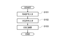
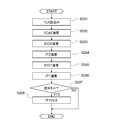
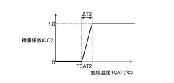
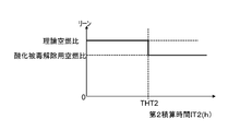
- FIG. 1 is a system configuration diagram of an internal combustion engine in an embodiment of the present invention. It is a flowchart which shows the detection process of the oxygen storage capacity OSC of the exhaust purification catalyst in embodiment of this invention. It is a flowchart which shows the integration process of 1st integration time IT1 and 2nd integration time IT2 in embodiment of this invention. It is a diagram which shows the correlation with the catalyst temperature TCAT of the exhaust gas purification catalyst and integration coefficient ICO2 in embodiment of this invention.
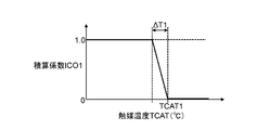
- FIG. 4 is a diagram showing a correlation between a catalyst temperature TCAT of an exhaust purification catalyst and an integration coefficient ICO1 in an embodiment of the present invention. It is a flowchart which shows the oxidation poisoning cancellation
- FIG. 1 is a diagram showing an aspect of an internal combustion engine to which a control device and a control method according to the present invention are applied.
- An internal combustion engine 1 shown in FIG. 1 is a spark ignition gasoline engine for a vehicle, and an ignition device 4, a fuel injection device 5, a rotation speed detection device 6 and the like are attached to an engine body 1a.
- the air sucked through the air cleaner 7 is adjusted in flow rate by the throttle valve 8 a of the electric throttle 8, and then mixed with the fuel injected from the fuel injection device 5 into the intake passage 2 a to enter the combustion chamber 10. Sucked.
- the electric throttle 8 is a device that opens and closes the throttle valve 8a with a throttle motor 8b, and is provided with a throttle opening sensor 8c that outputs a throttle valve opening signal TPS.
- a flow rate detection device 9 is arranged upstream of the electric control throttle 8, and the flow rate detection device 9 measures the intake air flow rate QAR of the internal combustion engine 1.
- the exhaust passage 3a is provided with an exhaust purification catalyst 12 having an oxygen storage capability such as a three-way catalyst.
- the exhaust gas of the internal combustion engine 1 is purified by the exhaust purification catalyst 12 and then discharged into the atmosphere. .
- an air-fuel ratio sensor 11 that outputs a detection signal RABF corresponding to the exhaust air-fuel ratio and an exhaust temperature sensor that detects an exhaust temperature TEX (° C.) at the inlet of the exhaust purification catalyst 12 are provided. 16 is arranged. Further, an oxygen sensor 15 that outputs a detection signal VO2R indicating a rich / lean state of the exhaust air / fuel ratio with respect to the stoichiometric air / fuel ratio is disposed in the exhaust passage 3a downstream of the exhaust purification catalyst 12. An air-fuel ratio sensor that linearly detects the exhaust air-fuel ratio can be arranged in the exhaust passage 3a downstream of the exhaust purification catalyst 12 in place of the oxygen sensor 15.
- the fuel in the fuel tank is adjusted to a predetermined pressure and supplied to the fuel injection device 5 by a fuel supply device (not shown).
- the control device 13 takes in the intake air flow rate QAR measured by the flow rate detection device 9, the rotation angle signal NE of the crankshaft output from the projection of the ring gear 14 by the rotation number detection device 6, and the like, and based on these, the fuel injection pulse width TI And the fuel injection device 5 is controlled based on the fuel injection amount TI.
- control device 13 takes in the detection signal RABF of the air-fuel ratio sensor 11 and the detection signal VO2R of the oxygen sensor 15, and corrects the fuel injection amount TI so that the air-fuel ratio of the internal combustion engine 1 approaches the target value. Perform feedback control. Further, the control device 13 outputs the operation amount to the ignition device 4 and the electric throttle 8, and controls the ignition timing of the ignition device 4 and the opening degree of the throttle valve 8 a to control the operation of the internal combustion engine 1.
- the control device 13 inputs and outputs various data such as measurement results of various sensors and operation amounts output to the various devices, in order to input / output various data such as an analog input circuit 20, an A / D conversion circuit 21, a digital input circuit 22, and an output circuit 23. And an I / O circuit 24.
- the control device 13 includes a microcomputer including an MPU 26, a ROM 27, and a RAM 28 in order to perform data calculation processing.
- the analog input circuit 20 includes an intake air flow rate QAR measured by the flow rate detection device 9, a throttle valve opening signal TPS detected by the throttle opening sensor 8c, a detection signal RABF of the air-fuel ratio sensor 11, and a detection signal of the oxygen sensor 15.
- VO2R is input.
- the intake air flow rate QAR, the throttle valve opening signal TPS, the detection signal RABF, and the detection signal VO2R input to the analog input circuit 20 are respectively supplied to the A / D conversion circuit 21 and converted into digital signals on the bus 25. Is output.
- crankshaft rotation angle signal NE input to the digital input circuit 22 is output to the bus 25 via the I / O circuit 24.
- An MPU 26, ROM 27, RAM 28, timer / counter (TMR / CNT) 29 and the like are connected to the bus 25, and data is exchanged via the bus 25.
- a clock signal is supplied from the clock generator 30 to the MPU 26, and various operations and processes are executed in synchronization with the clock signal.
- the ROM 27 is composed of, for example, an EEPROM capable of erasing and rewriting data.
- the ROM 27 stores a program for operating the control device 13, setting data, initial values, and the like. The data is read into the RAM 28 and the MPU 26 through 25.
- the RAM 28 is used as a work area and temporarily stores calculation results and processing results by the MPU 26.
- the timer / counter 29 is used for measuring time, measuring various times, and the like. Calculation results and processing results by the MPU 26 are output on the bus 25 and supplied to the ignition device 4, the fuel injection device 5, the electric throttle 8 and the like from the output circuit 23 via the I / O circuit 24.
- control device 13 has a function of detecting whether or not the exhaust purification catalyst 12 is poisoned and performing a poisoning release process when the occurrence of poisoning is detected as software.
- poisoning of the exhaust purification catalyst 12 detected by the control device 13 includes oxidation poisoning in which oxygen remains adsorbed on the noble metal and sulfur poisoning in which sulfur is adsorbed on the surface of the noble metal. That is, the control device 13 functions as a first poisoning detection unit that detects sulfur poisoning of the exhaust purification catalyst 12, and a first poisoning that performs a process of releasing sulfur poisoning when sulfur poisoning is detected.
- a function as a release unit a function as a second poisoning detection unit for detecting oxidation poisoning of the exhaust purification catalyst 12, and a second poisoning release for performing processing to release the oxidation poisoning when the oxidation poisoning is detected
- the function as a unit is provided as software.
- the control device 13 In order to detect sulfur poisoning and oxidation poisoning, the control device 13 accumulates the operating time of the internal combustion engine 1 in a state where the temperature TCAT of the exhaust purification catalyst 12 is lower than the first temperature TCAT1, and obtains the first accumulated time IT1. In addition, the operating time of the internal combustion engine 1 in a state where the temperature TCAT of the exhaust purification catalyst 12 exceeds the second temperature TCAT2 is integrated to obtain the second integrated time IT2, and further, the oxygen storage capacity OSC of the exhaust purification catalyst 12 is obtained. (O 2 Storage Capacity) is detected.
- the control device 13 detects sulfur poisoning of the exhaust purification catalyst 12 when the first cumulative time IT1 exceeds the first time THT1 and the oxygen storage capacity OSC falls below the first capacity OSC1, and the exhaust purification is performed. A sulfur poisoning release process for increasing the temperature of the catalyst 12 is performed. Further, the control device 13 detects oxidation poisoning of the exhaust purification catalyst 12 when the second integrated time IT2 exceeds the second time THT2, and releases the oxidation poisoning that changes the air-fuel ratio of the internal combustion engine 1 in the rich direction. Implement the process.
- the flowchart of FIG. 2 shows one mode of the detection process of the oxygen storage capacity OSC (g) by the control device 13. Note that the processing shown in the flowchart of FIG. 2 is executed by the control device 13 by interruption processing at regular intervals, for example.
- step S101 the control device 13 detects output characteristics such as the number of inversions and the period of the detection signal RABF of the air-fuel ratio sensor 11 in a state where the air-fuel ratio feedback control is being performed. To implement.
- step S102 the control device 13 performs monitoring processing of the detection signal VO2R to detect output characteristics such as the number of inversions and the period of the detection signal VO2R of the oxygen sensor 15 in the state where the air-fuel ratio feedback control is being performed. carry out.
- step S103 the control device 13 calculates a ratio or difference between the inversion number or cycle of the detection signal RABF and the inversion number or cycle of the detection signal VO2R, and based on this ratio or difference, the control device 13
- the oxygen storage capacity OSC (or data correlated with the oxygen storage capacity OSC) is calculated.
- the exhaust purification catalyst 12 has an oxygen storage capacity, stores oxygen when the inflowing exhaust gas is lean gas, and releases the oxygen stored so far when the inflowing exhaust gas is switched to rich gas, thereby purifying exhaust gas.
- a delay occurs when the exhaust air-fuel ratio downstream of the catalyst 12 switches to a rich state, and the delay increases as the oxygen storage capacity OSC increases. Therefore, the control device 13 detects the oxygen storage capacity OSC of the exhaust purification catalyst 12 using the above characteristics.
- the calculation process of the oxygen storage capacity OSC is not limited to the process based on the above difference or ratio, and the control device 13 can have a known OSC calculation function.
- the control device 13 forcibly controls the air-fuel ratio of the exhaust gas flowing into the exhaust purification catalyst 12 to be richer and leaner than the stoichiometric air-fuel ratio, and the exhaust purification catalyst 12 releases oxygen from the state of the maximum oxygen storage amount.
- the time for which the exhaust purification catalyst 12 continues to store oxygen from the state of the minimum oxygen storage amount can be obtained as data corresponding to the oxygen storage capacity OSC.
- the control device 13 can obtain the integrated value of the oxygen storage amount and the oxygen release amount per calculation cycle in the period during which the exhaust purification catalyst 12 continues to store or release oxygen as data corresponding to the oxygen storage capacity OSC. .
- the flowchart of FIG. 3 shows one aspect of the calculation process of the first integrated time IT1 and the second integrated time IT2 by the control device 13. Note that the processing illustrated in the flowchart of FIG. 3 is executed by the control device 13 by interruption processing at regular intervals, for example.
- the control device 13 reads the exhaust temperature TEX at the inlet of the exhaust purification catalyst 12 detected by the exhaust temperature sensor 16 in step S201, and estimates the temperature TCAT of the exhaust purification catalyst 12 based on the exhaust temperature TEX in the next step S202. To do. In the process of estimating the temperature TCAT of the exhaust purification catalyst 12 based on the exhaust temperature TEX, the control device 13 can estimate that the temperature TCAT follows the change in the exhaust temperature TEX with a predetermined delay, for example.
- the control device 13 determines the engine rotational speed, engine load, total fuel consumption, exhaust flow rate, outside air temperature, cooling water temperature, lubricating oil temperature, and the like.
- the temperature TCAT can be estimated from the operating conditions.
- the internal combustion engine 1 may include a catalyst temperature sensor that detects the internal temperature of the exhaust purification catalyst 12, and the control device 13 may obtain the temperature TCAT from the output signal of the catalyst temperature sensor.
- step S203 the control device 13 calculates the second integration time IT2 that is an integration value of the operation time of the internal combustion engine 1 in a state where the temperature TCAT of the exhaust purification catalyst 12 exceeds the second temperature TCAT2.
- the coefficient ICO2 is set based on the temperature TCAT of the exhaust purification catalyst 12 (see FIG. 4).
- the integration coefficient ICO2 is a correction coefficient that multiplies the calculation period of the integration coefficient ICO2 in the calculation process in which the result obtained by adding the calculation period of the integration coefficient ICO2 to the previous value of the second integration time IT2 is the current value.
- the second integration time IT2 is held at the previous value, and if the integration coefficient ICO2 is 1, the calculation cycle is added to the previous value as it is, and the addition result is the second integration time IT2. This value is set this time.
- the second temperature TCAT2 is a lower limit temperature in a high temperature range in which oxidative poisoning in which oxygen remains adsorbed on the noble metal of the exhaust purification catalyst 12 is set, for example, a temperature of about 700 ° C. to 800 ° C.
- the control device 13 stops the integration of the second integration time IT2 by setting the integration coefficient ICO2 to zero (FIG. 4). reference).
- the control device 13 gradually increases the integration coefficient ICO2 from zero as the temperature TCAT of the exhaust purification catalyst 12 becomes higher than the second temperature TCAT2, and the temperature TCAT of the exhaust purification catalyst 12 is higher than the second temperature TCAT2.
- the integration coefficient ICO2 is set to 1 (see FIG. 4). That is, in the temperature range where the temperature TCAT of the exhaust purification catalyst 12 is slightly higher than the second temperature TCAT2, in other words, in the temperature range closer to the low temperature (TCAT2 to TCAT2 + ⁇ T2) within the temperature range where oxidation poisoning is estimated to proceed. It is estimated that the progress of oxidative poisoning is slower than in the higher temperature range.
- the control device 13 reduces the weighting of the operation time as the temperature TCAT of the exhaust purification catalyst 12 is closer to the second temperature TCAT2 in the temperature range equal to or higher than the second temperature TCAT2, and conversely, the temperature TCAT of the exhaust purification catalyst 12 When the temperature is sufficiently higher than the second temperature TCAT2, the weighting of the operation time is increased.
- the integration coefficient ICO2 can be set to zero in a temperature range lower than the second temperature TCAT2 and to 1 in a temperature range higher than the second temperature TCAT2.
- step S203 When the integration coefficient ICO2 is set in step S203, the control device 13 proceeds to step S204, and performs an update process for the second integration time IT2.
- the control device 13 adds the value obtained by multiplying the execution cycle PT (ms) of this routine by the integration coefficient ICO2 to the second integration time IT2 (n-1) at the previous execution of this routine,
- the second integrated time IT2 calculated according to the above equation is an internal combustion engine in a state in which the temperature TCAT of the exhaust purification catalyst 12 exceeds the second temperature TCAT2, in other words, a temperature condition in which oxidative poisoning of the exhaust purification catalyst 12 proceeds. This is the total operating time of the engine 1.
- the control device 13 calculates the first integration time IT1, which is an integration value of the operation time of the internal combustion engine 1 when the temperature TCAT of the exhaust purification catalyst 12 is lower than the first temperature TCAT1.
- the coefficient ICO1 is set based on the temperature TCAT of the exhaust purification catalyst 12 (see FIG. 5).
- the first temperature TCAT1 is an upper limit temperature in a low and middle temperature range where sulfur poisoning proceeds in the exhaust purification catalyst 12, and is set to a temperature of about 750 ° C. to 850 ° C., for example.
- the control device 13 stops the integration of the first integration time IT1 by setting the integration coefficient ICO1 to zero (see FIG. 5). ).
- the integration coefficient ICO1 is set to 1 below the lower temperature (see FIG. 5). That is, the temperature range TCAT of the exhaust purification catalyst 12 is slightly lower than the first temperature TCAT1, in other words, the temperature range closer to the high temperature (TCAT1- ⁇ T1 to TCAT1) within the temperature range where sulfur poisoning is estimated to progress. In this case, it is estimated that the progress of sulfur poisoning is slower than in the lower temperature range.
- the control device 13 reduces the weighting of the operation time as the temperature TCAT of the exhaust purification catalyst 12 is closer to the first temperature TCAT1 in the temperature range below the first temperature TCAT1, and conversely, the temperature TCAT of the exhaust purification catalyst 12 When the temperature is sufficiently lower than the first temperature TCAT1, the operating time is weighted more heavily.
- the integration coefficient ICO1 can be set to zero in a temperature range higher than the first temperature TCAT1 and to 1 in a temperature range lower than the first temperature TCAT1.
- step S205 When the integration coefficient ICO2 is set in step S205, the control device 13 proceeds to step S206, and performs an update process for the first integration time IT1.
- the control device 13 adds the value obtained by multiplying the execution cycle PT (ms) of this routine by the integration coefficient ICO1 to the first integration time IT1 (n-1) at the previous execution of this routine, and obtains the result of the first integration.
- the first integrated time IT1 calculated according to the above equation is an internal combustion engine in a state where the temperature TCAT of the exhaust purification catalyst 12 is lower than the first temperature TCAT1, in other words, a temperature condition where sulfur poisoning of the exhaust purification catalyst 12 proceeds. This is the total operating time of the engine 1.
- the control device 13 proceeds to step S207, and determines whether or not the fuel cut in a state where the temperature TCAT of the exhaust purification catalyst 12 is higher than the determination temperature SCTHT has been performed for a predetermined time FCT or more.
- the fuel cut is a process in which the control device 13 temporarily stops fuel injection by the fuel injection device 5 when the internal combustion engine 1 is decelerated.
- the determination temperature SCTHT is a minimum value in a high temperature range in which sulfur accumulated in the exhaust purification catalyst 12 is removed in a short time when exhaust gas having the maximum lean air-fuel ratio flows into the exhaust purification catalyst 12 due to fuel cut. .
- the predetermined time FCT is determined so that the exhaust purification catalyst 12 is exposed to a high-temperature oxidizing atmosphere when the fuel cut is performed under a temperature condition higher than the determination temperature SCTHT.
- This time is estimated to be almost complete, and is set to about 8 to 10 seconds, for example. That is, when the fuel cut is performed for the predetermined time FCT or more in a state where the temperature TCAT of the exhaust purification catalyst 12 is higher than the determination temperature SCTHT, the control device 13 determines that the sulfur accumulated in the exhaust purification catalyst 12 has been removed.
- the process proceeds to step S208, and the first integrated time IT1 for determining the progress of sulfur poisoning is reset to zero.
- the control device 13 continues to update the first integrated time IT1 as it is despite the fuel cut that removes the sulfur accumulated in the exhaust purification catalyst 12 being performed, and the sulfur coverage of the exhaust purification catalyst 12 is maintained. It is possible to suppress erroneous detection of the progress of the poison. Note that the controller 13 repeats the fuel cut several times within a certain time even when the fuel cut execution duration under the temperature condition higher than the determination temperature SCTHT is less than the predetermined time FCT. When the total fuel cut time exceeds the set time, it is estimated that sulfur has been removed, and the first integrated time IT1 can be reset to zero.
- the flowchart of FIG. 6 shows one aspect of the sulfur poisoning / oxidation poisoning detection process and the poisoning release process performed by the control device 13.
- the control device 13 determines the oxygen storage capacity OSC obtained by the process shown in the flowchart of FIG. 2 and the first accumulated time obtained by the process shown in the flowchart of FIG. 3. IT1 and second integrated time IT2 are used. Note that the processing shown in the flowchart of FIG. 6 is executed, for example, by interrupt processing at regular intervals by the control device 13.
- step S301 the control device 13 reads the latest calculated values of the oxygen storage capacity OSC, the first accumulated time IT1, and the second accumulated time IT2 stored in the RAM 28.
- the control device 13 cancels the oxidative poisoning. In other words, the amount of oxygen remaining adsorbed on the exhaust purification catalyst 12 exceeds the allowable maximum amount. Estimated. Then, when the second integrated time IT2 exceeds the second time THT2, the control device 13 proceeds to step S303 and performs the oxidation poisoning release process for a predetermined time TC2.
- the control device 13 sets the air-fuel ratio (average air-fuel ratio) of the internal combustion engine 1 from the stoichiometric air-fuel ratio when the temperature TCAT of the exhaust purification catalyst 12 is in the temperature range exceeding the oxidation determination temperature OCTHT.
- the control device 13 temporarily stops the oxidation poisoning release process, and When the temperature TCAT exceeds the judgment temperature OCTHT, the oxidation poisoning release process is restarted, and when the total time for performing the oxidation poisoning release process reaches a predetermined time TC2, the oxidation poisoning release is performed. Complete the process.
- step S303 the control device 13 performs the oxidation poisoning release process, and in the next step S304, the second integrated time IT2 is reset to zero.
- the control device 13 resets the second accumulated time IT2 to zero when starting the oxidation poisoning release process, and stops the accumulation of the second accumulated time IT2 until the oxidation poisoning release process is completed. Then, after the oxidation poisoning release process is completed, the integration of the second integration time IT2 can be resumed.
- control device 13 can reset the second integrated time IT2 to zero when the oxidation poisoning release process is completed, and can update the second integrated time IT2 as time elapses from the reset time.
- the second integrated time IT2 which is the total operation time of the internal combustion engine 1 under the temperature condition where the temperature TCAT of the exhaust purification catalyst 12 exceeds the second temperature TCAT2, exceeds the second time THT2
- the second time THT2 is added again from zero.
- step S305 the control device 13 determines whether or not the first accumulated time IT1 exceeds the first time THT1.
- the sulfur poisoning release process is required to be performed. There is a possibility that sulfur poisoning of the exhaust purification catalyst 12 is progressing as much as possible.
- the first integration time IT1 reaches the first time THT1 earlier than the second integration time IT2 reaches the second time THT2, and the progress of sulfur poisoning is uniform according to the increase in the first integration time IT1.
- the correlation between the first integrated time IT1 and the degree of progress of sulfur poisoning varies.
- the control device 13 proceeds to step S306 when the first cumulative time IT1 exceeds the first time THT1, and the exhaust purification catalyst. It is determined whether or not the oxygen storage capacity OSC of 12 is less than the first capacity OSC1.
- the oxygen storage capacity OSC of the exhaust purification catalyst 12 is reduced by sulfur poisoning by reducing the noble metal surface area of the exhaust purification catalyst 12 by sulfur (SOx compound) adhering to the catalyst surface. Will be less than when not. Therefore, when the total operation time at the catalyst temperature at which sulfur poisoning proceeds exceeds the determination time and the oxygen storage capacity OSC is reduced, the control device 13 requests execution of the sulfur poisoning release process. And the process proceeds to step S307. In step S307, the control device 13 performs the sulfur poisoning release process for a predetermined time TC1.
- the control device 13 performs control for increasing the temperature TCAT of the exhaust purification catalyst 12 to be higher than the poisoning release processing temperature SPCT as the sulfur poisoning release processing, and adheres to the noble metal surface of the exhaust purification catalyst 12 by such temperature control.
- the sulfur is removed.
- the sulfur accumulated in the noble metal of the exhaust purification catalyst 12 is removed regardless of the rich / lean ratio of the air / fuel ratio of the internal combustion engine 1 to the stoichiometric air / fuel ratio.
- the controller 13 raises the temperature TCAT of the exhaust purification catalyst 12 to such a temperature condition and releases the sulfur poisoning in a short time (see JP 2012-057576 A, etc.). .
- the control device 13 can perform control for making the average air-fuel ratio of the internal combustion engine 1 leaner than the stoichiometric air-fuel ratio as well as controlling the temperature TCAT of the exhaust purification catalyst 12 as sulfur poisoning release processing.
- the control device 13 can perform various known processes, for example, enrichment of the air-fuel ratio, correction of ignition timing retardation, At least one of stopping the exhaust gas recirculation, increasing the engine rotational speed, increasing the intake air flow rate, changing the valve timing, etc. is performed to increase the exhaust temperature of the internal combustion engine 1, and thereby the exhaust purification catalyst 12.
- the temperature TCAT can be increased.
- the control device 13 can change the gear ratio of the transmission combined with the internal combustion engine in the vehicle to be low in order to increase the engine rotation speed.
- a heater for heating the exhaust purification catalyst 12 is provided, and the control device 13 operates the heater as a sulfur poisoning release process, and the temperature TCAT of the exhaust purification catalyst 12 becomes higher than the poisoning release treatment temperature SPCT by heating with the heater. Can be raised.
- the control device 13 performs the sulfur cut by the fuel cut. It is assumed that the release of poisoning has been completed, and the sulfur poisoning release process is terminated.
- the controller 13 performs the sulfur poisoning release process in step S307, and resets the first integrated time IT1 to zero in the next step S308.
- the control device 13 resets the first integrated time IT1 to zero when starting the sulfur poisoning release process, and stops the integration of the first integrated time IT1 until the sulfur poisoning release process is completed. Then, after the sulfur poisoning release process is completed, the integration of the first integration time IT1 can be resumed.
- control device 13 can reset the first integration time IT1 to zero when the sulfur poisoning release process is completed, and integrate the first integration time IT1 as time elapses from the reset time.
- control device 13 determines in step S306 that the oxygen storage capacity OSC of the exhaust purification catalyst 12 is greater than or equal to the first capacity OSC1
- the control apparatus 13 bypasses step S307 (sulfur poisoning release processing) and proceeds to step S308.
- the first integration time IT1 is reset to zero.
- the control device 13 estimates that sulfur poisoning that actually requires a release process has not occurred. Do not carry out sulfur poisoning release processing. Note that if the control device 13 determines in step S306 that the oxygen storage capacity OSC of the exhaust purification catalyst 12 is greater than or equal to the first capacity OSC1, the first integrated time IT1 is not reset to zero, but the first time THT1. The first integrated time IT1 reaches the first time THT1 in a shorter operation time than when reset to zero and is shifted to a time shorter than zero and configured to determine whether or not the oxygen storage capacity OSC has decreased. can do.
- the control device 13 next selects the oxygen storage capacity.
- the operating time until it is determined whether the OSC is less than or equal to the first capacity OSC1 is changed to a short time, and the sulfur poisoning is progressing to a level that requires the release process, but the release process is not performed and left. Can be deterred.
- the control device 13 determines whether or not oxidation poisoning and sulfur poisoning have occurred as described above, and performs the poisoning release processing. Further, in step S309, the oxygen storage capacity OSC is set to the second capacity OSC2. It is determined whether or not it is less than (first capacity OSC1> second capacity OSC2).
- the second capacity OSC2 is a threshold value for determining whether or not the reduction in the purification performance of the exhaust purification catalyst 12 exceeds an allowable level.
- the control device No. 13 estimates that the purification performance of the exhaust purification catalyst 12 has fallen beyond an acceptable level.
- the control device 13 cannot detect the occurrence of poisoning with good response based on the first integrated time IT1 and the second integrated time IT2.
- the controller 13 causes the oxygen storage capacity OSC to fall below the second capacity OSC2. Therefore, a sudden decrease in the oxygen storage capacity OSC due to poisoning can be detected.
- the control device 13 determines that when the oxygen storage capacity OSC falls below the second capacity OSC2, this is the sulfur poisoning, oxidation poisoning. It cannot be distinguished whether it is due to poison or not. Therefore, when the oxygen storage capacity OSC is lower than the second capacity OSC2 and the recovery of the oxygen storage capacity OSC is required, the control device 13 proceeds to step S310, and performs the sulfur poisoning release process and the oxidation poisoning release process. Implement both.
- step S310 when the temperature TCAT of the exhaust purification catalyst 12 is lower than the poisoning release processing temperature SPCT, the control device 13 performs control to increase the temperature TCAT of the exhaust purification catalyst 12 to be higher than the poisoning release processing temperature SPCT. In addition, control is performed to make the air-fuel ratio of the internal combustion engine 1 slightly rich when the temperature TCAT of the exhaust purification catalyst 12 is in a temperature range that exceeds the oxidation determination temperature OCTHT.
- the control for increasing the temperature TCAT of the exhaust purification catalyst 12 to be higher than the poisoning release processing temperature SPCT raises the temperature TCAT of the exhaust purification catalyst 12 to a temperature at which sulfur is removed regardless of the rich / lean of the air / fuel ratio.
- control by performing air-fuel ratio control that makes the air-fuel ratio weakly rich in parallel with such temperature control, sulfur poisoning release processing and oxidation poisoning release processing are performed simultaneously.
- the sulfur poisoning release process includes air-fuel ratio control that makes the air-fuel ratio leaner than the stoichiometric air-fuel ratio, the direction of shifting the air-fuel ratio is opposite to the enrichment process of the oxidation poisoning release process,
- the control device 13 can preferentially perform either the leaning process as the sulfur poisoning cancellation process or the enrichment process as the oxidation poisoning cancellation process, and then perform the remaining air-fuel ratio process.
- the control device 13 gives priority to a shorter time required for detoxification among a sulfur poisoning desorption process for performing lean air-fuel ratio and an oxidative poisoning deactivation process for performing weak enrichment of air-fuel ratio.
- the oxygen storage capacity OSC of the exhaust purification catalyst 12 can be recovered quickly. Since the control device 13 performs both the sulfur poisoning release processing and the oxidation poisoning release processing in step S310 to release both the sulfur poisoning and the oxidation poisoning, the first integration is performed in the next step S311.
- the time IT1 and the second accumulated time IT2 are reset to zero, and the progress of sulfur poisoning and oxidative poisoning after the poisoning release processing in step S310 is detected based on the first accumulated time IT1 and the second accumulated time IT2. Like that.
- control device 13 can determine the rate of decrease in the oxygen storage capacity OSC as a condition for proceeding from step S309 to step S310. For example, the control device 13 determines, for example, when the rate of decrease of the oxygen storage capacity OSC with respect to the operating time of the internal combustion engine 1 exceeds the determination speed, or when the oxygen storage capacity OSC is lower than the first capacity OSC1 and decreases. Is higher than the determination speed, the process proceeds from step S309 to step S310, and the sulfur poisoning release process and the oxidation poisoning release process can be performed.
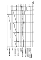
- FIG. 8 is a time chart illustrating an execution pattern of the oxidation poisoning cancellation process and the sulfur poisoning cancellation process performed by the control device 13.
- the fuel cut flag is a flag that is raised when the fuel cut is performed for a predetermined time FCT or more in a state where the temperature TCAT of the exhaust purification catalyst 12 is higher than the determination temperature SCTHT.
- the process proceeds from step S207 to step S208 in the flowchart of FIG.
- the first integrated time IT1 for determining the progress of sulfur poisoning does not reach the first time THT1, but the fuel cut flag is raised.
- the rise of the fuel cut flag indicates that the fuel cut was performed for a predetermined time FCT or more in a state where the temperature TCAT of the exhaust purification catalyst 12 is higher than the determination temperature SCTHT, and the sulfur accumulated in the exhaust purification catalyst 12 by the fuel cut. Is removed, the control device 13 resets the first integration time IT1 to zero.
- the process of resetting the first integrated time IT1 to zero is a pattern that proceeds from step S207 to step S208 in FIG.
- the first integrated time IT1 has reached the first time THT1, and the first integrated time IT1 is at a level that is required for the sulfur poisoning release process.
- the oxygen storage capacity OSC of the exhaust purification catalyst 12 at that time is larger than the first capacity OSC1, and the precious metal area of the exhaust purification catalyst 12 is not reduced more than a predetermined amount due to sulfur poisoning. Therefore, at the time t3, the control device 13 resets the first integrated time IT1 to zero without performing the sulfur poisoning release process.
- the process of resetting the first integration time IT1 to zero is a pattern that proceeds from step S306 to step S308 in FIG.
- the control device 13 performs the oxidation poisoning release process and resets the second integrated time IT2 to zero.
- release process and resets the 2nd integration time IT2 to zero is a pattern which progresses to step S303 and step S304 from step S302 in FIG.
- the first integrated time IT1 has reached the first time THT1, and the oxygen storage capacity OSC at that time is lower than the first capacity OSC1, so the control device 13 Estimates that the precious metal area of the exhaust purification catalyst 12 is reduced by more than a predetermined amount due to sulfur poisoning, in other words, a state in which removal of sulfur from the exhaust purification catalyst 12 is required, and cancels sulfur poisoning.
- the process is executed and the first integration time IT1 is reset to zero.
- release process and resets 1st integration time IT1 to zero is a pattern which progresses to step S307 and step S308 from step S306 of FIG.
- the first integrated time IT1 is lower than the first time THT1
- the second integrated time IT2 is lower than the second time THT2
- the accumulated time IT2 does not indicate the occurrence of sulfur poisoning or oxidation poisoning in the exhaust purification catalyst 12, but the oxygen storage capacity OSC of the exhaust purification catalyst 12 is equal to the second capacity OSC2 (second capacity OSC2 ⁇ first capacity OSC1). It is below. In this case, due to the use of high-sulfur concentration fuel or misfire at high temperatures, rapid poisoning that is earlier than the progress of sulfur poisoning and oxidation poisoning estimated from the first cumulative time IT1 and the second cumulative time IT2 occurs.
- control device 13 Since it is estimated that it has occurred, the control device 13 performs the oxidation poisoning release process and the sulfur poisoning release process, and resets the first accumulated time IT1 and the second accumulated time IT2 to zero.
- release process, and resets the 1st integration time IT1 and the 2nd integration time IT2 to zero progresses to step S310 and step S311 of FIG. It is a pattern.
- the control device 13 determines whether the oxygen storage capacity OSC at the time when the first integrated time IT1 reaches the first time THT1 is higher or lower than the first capacity OSC1 next time. The total operation time until the first time THT1 is reached can be changed.
- the control device 13 makes progress of sulfur poisoning with respect to the first cumulative time IT1.
- the total operation time until the first integration time IT1 reaches the first time THT1 next time is shortened, The detection response of sulfur poisoning can be improved.
- the control device 13 proceeds with the sulfur poisoning with respect to the first cumulative time IT1.
- the control device 13 detects the oxygen storage capacity OSC lower than the second capacity OSC2 and performs both the sulfur poisoning release process and the oxidative poisoning release process, the fuel having a sulfur concentration higher than the specified level is detected. Since there is a possibility that it is being used, the determination period of sulfur poisoning is changed to a short time by adapting to the state where the sulfur poisoning progresses quickly by decreasing the first time THT1 or increasing the integration coefficient ICO1. be able to. Further, the control device 13 determines the first time THT1 and / or the integration coefficient ICO1 in accordance with a property correlated with the sulfur concentration of the gasoline fuel used by the internal combustion engine 1, for example, one of high-octane gasoline and regular gasoline. , And the sulfur poisoning determination cycle can be made different.
- SYMBOLS 1 Internal combustion engine, 4 ... Ignition device, 5 ... Fuel injection device, 6 ... Rotational speed detection device, 8 ... Electric throttle, 8c ... Throttle opening sensor, 9 ... Flow rate detection device, 11 ... Air-fuel ratio sensor, 12 ... Exhaust purification catalyst, 13 ... control device, 15 ... oxygen sensor, 16 ... exhaust temperature sensor
Landscapes
- Engineering & Computer Science (AREA)
- Chemical & Material Sciences (AREA)
- Combustion & Propulsion (AREA)
- Mechanical Engineering (AREA)
- General Engineering & Computer Science (AREA)
- Chemical Kinetics & Catalysis (AREA)
- Analytical Chemistry (AREA)
- Health & Medical Sciences (AREA)
- Toxicology (AREA)
- Exhaust Gas After Treatment (AREA)
- Electrical Control Of Air Or Fuel Supplied To Internal-Combustion Engine (AREA)
- Combined Controls Of Internal Combustion Engines (AREA)
Abstract
本願発明の内燃機関の制御装置及び制御方法は、排気浄化触媒の温度TCATが第1温度を下回る状態での運転時間を積算して第1積算時間IT1を求めるとともに、排気浄化触媒の酸素吸蔵容量OSCを検出し、第1積算時間IT1が第1時間THT1を超え、かつ、酸素吸蔵容量OSCが第1容量OSC1を下回ったときに、硫黄被毒を解除するため処理を実施し、排気浄化触媒の温度TCATが第2温度TCAT2を上回る状態での運転時間を積算して第2積算時間IT2を求め、第2積算時間IT2が第2時間THT2を超えたときに、酸化被毒を解除するための処理を実施する。
Description
本発明は、内燃機関の制御装置及び制御方法に関し、詳しくは、排気浄化触媒の被毒を検出して被毒解除処理を実施する技術に関する。
特許文献1には、燃料性状の違いによる硫黄濃度の違いに対応して、排気浄化触媒の被毒解除処理を過不足なく行わせ、燃費の悪化や触媒の熱劣化の発生を防止するために、ハイオクガソリンでの走行距離HMILEとレギュラーガソリンでの走行距離RMILEとを個別に積算させ、HMILE+RMILEが閾値以上になったときに、被毒解除要求を発生させる、内燃機関の排気浄化装置が開示されている。
排気浄化触媒の硫黄被毒を検出する場合、同じレギュラーガソリンでも硫黄濃度にばらつきがあるため、内燃機関が搭載される車両の走行距離や内燃機関の運転時間の積算値などから硫黄被毒の検出を行うと、高い精度で硫黄被毒を検出できず、実際には硫黄被毒状態であるのに被毒解除処理が実施されず、排気浄化触媒が被毒状態のまま放置されてしまう可能性がある。
ここで、排気浄化触媒が被毒状態に放置されることを抑制するために、走行距離や運転時間などに基づき被毒解除処理を実施するタイミングを早めに設定すると、過剰な被毒解除処理によって燃費性能などが低下するという問題が生じる。
ここで、排気浄化触媒が被毒状態に放置されることを抑制するために、走行距離や運転時間などに基づき被毒解除処理を実施するタイミングを早めに設定すると、過剰な被毒解除処理によって燃費性能などが低下するという問題が生じる。
本発明は上記問題点に鑑みなされたものであり、排気浄化触媒の被毒を的確に検出でき、以って、排気浄化触媒が被毒状態に放置されることを抑制しつつ、被毒解除処理が過剰に実施されることを抑制できる、内燃機関の制御装置及び制御方法を提供することを目的とする。
そのため、本願発明に係る内燃機関の制御装置は、その一態様において、排気管に排気浄化触媒を備えた内燃機関に適用される制御装置であって、前記排気浄化触媒の温度が第1温度を下回る状態での前記内燃機関の運転時間を積算して第1積算時間を求める第1積算部と、前記排気浄化触媒の酸素吸蔵容量を検出する容量検出部と、前記第1積算時間が第1時間を超え、前記酸素吸蔵容量が第1容量を下回ったときに、前記排気浄化触媒の被毒を検出する第1被毒検出部と、前記第1被毒検出部が前記排気浄化触媒の被毒を検出したときに、前記排気浄化触媒の温度を上昇させる被毒解除処理を実施する第1被毒解除部と、を含む。
また、本願発明に係る内燃機関の制御方法は、その一態様において、排気管に排気浄化触媒を備えた内燃機関の制御方法であって、前記排気浄化触媒の温度が第1温度を下回る状態での前記内燃機関の運転時間を積算して第1積算時間を求めるステップと、前記排気浄化触媒の酸素吸蔵容量を検出するステップと、前記第1積算時間が第1時間を超え、前記酸素吸蔵容量が第1容量を下回ったときに、前記排気浄化触媒の温度を上昇させる被毒解除処理を実施するステップと、を含む。
上記発明によると、排気浄化触媒が被毒した状態で的確に被毒解除処理を実施させることができ、被毒解除処理が過剰に実施されることや排気浄化触媒が被毒状態のまま放置されることを抑制できる。
以下に本発明の実施の形態を説明する。
図1は、本発明に係る制御装置及び制御方法を適用する内燃機関の一態様を示す図である。
図1に示す内燃機関1は、車両用の火花点火ガソリン機関であり、機関本体1aに点火装置4、燃料噴射装置5及び回転数検出装置6などが取り付けられている。
図1は、本発明に係る制御装置及び制御方法を適用する内燃機関の一態様を示す図である。
図1に示す内燃機関1は、車両用の火花点火ガソリン機関であり、機関本体1aに点火装置4、燃料噴射装置5及び回転数検出装置6などが取り付けられている。
エアークリーナ7を介して吸入される空気は、電制スロットル8のスロットルバルブ8aで流量を調節された後、燃料噴射装置5から吸気通路2a内に噴射される燃料と混合されて燃焼室10に吸引される。
電制スロットル8は、スロットルモータ8bでスロットルバルブ8aを開閉駆動する装置であり、スロットルバルブ開度信号TPSを出力するスロットル開度センサ8cが設けられている。
電制スロットル8は、スロットルモータ8bでスロットルバルブ8aを開閉駆動する装置であり、スロットルバルブ開度信号TPSを出力するスロットル開度センサ8cが設けられている。
電制スロットル8の上流には流量検出装置9が配置され、流量検出装置9は、内燃機関1の吸入空気流量QARを計測する。
また、排気通路3aには三元触媒などの酸素吸蔵能力を有する排気浄化触媒12が設けられており、内燃機関1の排気はこの排気浄化触媒12で浄化された後、大気中に排出される。
また、排気通路3aには三元触媒などの酸素吸蔵能力を有する排気浄化触媒12が設けられており、内燃機関1の排気はこの排気浄化触媒12で浄化された後、大気中に排出される。
排気浄化触媒12の上流の排気通路3aには、排気空燃比に対応する検出信号RABFを出力する空燃比センサ11及び排気浄化触媒12の入口での排気温度TEX(℃)を検出する排気温度センサ16が配置される。
また、排気浄化触媒12の下流の排気通路3aには、排気空燃比の理論空燃比に対するリッチ・リーンを示す検出信号VO2Rを出力する酸素センサ15が配置される。
なお、排気浄化触媒12の下流の排気通路3aに、酸素センサ15に代えて、排気空燃比をリニアに検出する空燃比センサを配置することができる。
また、排気浄化触媒12の下流の排気通路3aには、排気空燃比の理論空燃比に対するリッチ・リーンを示す検出信号VO2Rを出力する酸素センサ15が配置される。
なお、排気浄化触媒12の下流の排気通路3aに、酸素センサ15に代えて、排気空燃比をリニアに検出する空燃比センサを配置することができる。
燃料噴射装置5には、図示省略した燃料供給装置によって燃料タンク内の燃料が所定圧力に調整されて供給される。
制御装置13は、流量検出装置9で測定した吸入空気流量QAR、回転数検出装置6がリングギア14の突起によって出力するクランクシャフトの回転角信号NEなどを取り込み、これらに基づき燃料噴射パルス幅TIを演算し、燃料噴射量TIに基づき燃料噴射装置5を制御する。
制御装置13は、流量検出装置9で測定した吸入空気流量QAR、回転数検出装置6がリングギア14の突起によって出力するクランクシャフトの回転角信号NEなどを取り込み、これらに基づき燃料噴射パルス幅TIを演算し、燃料噴射量TIに基づき燃料噴射装置5を制御する。
また、制御装置13は、空燃比センサ11の検出信号RABFと酸素センサ15の検出信号VO2Rとを取り込み、内燃機関1の空燃比が目標値に近づくように燃料噴射量TIを補正する、空燃比のフィードバック制御を行う。
更に、制御装置13は、点火装置4、電制スロットル8にも操作量を出力し、点火装置4の点火時期やスロットルバルブ8aの開度を制御して、内燃機関1の運転を制御する。
更に、制御装置13は、点火装置4、電制スロットル8にも操作量を出力し、点火装置4の点火時期やスロットルバルブ8aの開度を制御して、内燃機関1の運転を制御する。
制御装置13は、各種センサの計測結果や各種装置に出力する操作量などの各種データの入出力を行うために、アナログ入力回路20、A/D変換回路21、デジタル入力回路22、出力回路23及びI/O回路24を備えている。
また、制御装置13は、データの演算処理を行うために、MPU26、ROM27、RAM28を含むマイクロコンピュータを備えている。
また、制御装置13は、データの演算処理を行うために、MPU26、ROM27、RAM28を含むマイクロコンピュータを備えている。
アナログ入力回路20には、流量検出装置9で測定した吸入空気流量QAR、スロットル開度センサ8cで検出したスロットルバルブ開度信号TPS、空燃比センサ11の検出信号RABF、及び酸素センサ15の検出信号VO2Rが入力される。
アナログ入力回路20に入力された吸入空気流量QAR、スロットルバルブ開度信号TPS、検出信号RABF、及び検出信号VO2Rはそれぞれ、A/D変換回路21に供給されてデジタル信号に変換され、バス25上に出力される。
アナログ入力回路20に入力された吸入空気流量QAR、スロットルバルブ開度信号TPS、検出信号RABF、及び検出信号VO2Rはそれぞれ、A/D変換回路21に供給されてデジタル信号に変換され、バス25上に出力される。
また、デジタル入力回路22に入力されたクランクシャフトの回転角信号NEは、I/O回路24を介してバス25上に出力される。
バス25には、MPU26、ROM27、RAM28、タイマ/カウンタ(TMR/CNT)29等が接続されており、当該バス25を介してデータの授受を行うようになっている。
バス25には、MPU26、ROM27、RAM28、タイマ/カウンタ(TMR/CNT)29等が接続されており、当該バス25を介してデータの授受を行うようになっている。
MPU26には、クロックジェネレータ30からクロック信号が供給され、このクロック信号に同期して様々な演算や処理が実行される。
ROM27は、例えばデータの消去と書き換えが可能なEEPROMで構成され、制御装置13を動作させるためのプログラム、設定データ及び初期値等が記憶されており、エンジンスイッチのオン等によりこれらの情報がバス25を介してRAM28及びMPU26に読み込まれる。
ROM27は、例えばデータの消去と書き換えが可能なEEPROMで構成され、制御装置13を動作させるためのプログラム、設定データ及び初期値等が記憶されており、エンジンスイッチのオン等によりこれらの情報がバス25を介してRAM28及びMPU26に読み込まれる。
RAM28は、作業領域として用いられ、MPU26による演算結果や処理結果を一時的に記憶するようになっている。なお、タイマ/カウンタ29は、時間の測定や様々な回数の測定などに用いられる。
MPU26による演算結果や処理結果はバス25上に出力され、I/O回路24を介して出力回路23から点火装置4、燃料噴射装置5及び電制スロットル8などに供給される。
MPU26による演算結果や処理結果はバス25上に出力され、I/O回路24を介して出力回路23から点火装置4、燃料噴射装置5及び電制スロットル8などに供給される。
また、制御装置13は、排気浄化触媒12の被毒の有無を検出し、被毒の発生を検出したときに被毒解除処理を実施する機能をソフトウェアとして備える。ここで、制御装置13が検出する排気浄化触媒12の被毒には、貴金属に酸素が吸着したままとなる酸化被毒と、貴金属表面に硫黄が吸着する硫黄被毒とが含まれる。
つまり、制御装置13は、排気浄化触媒12の硫黄被毒を検出する第1被毒検出部としての機能、硫黄被毒を検出したときに硫黄被毒を解除する処理を実施する第1被毒解除部としての機能、排気浄化触媒12の酸化被毒を検出する第2被毒検出部としての機能、酸化被毒を検出したときに酸化被毒を解除する処理を実施する第2被毒解除部としての機能をソフトウェアとして備える。
つまり、制御装置13は、排気浄化触媒12の硫黄被毒を検出する第1被毒検出部としての機能、硫黄被毒を検出したときに硫黄被毒を解除する処理を実施する第1被毒解除部としての機能、排気浄化触媒12の酸化被毒を検出する第2被毒検出部としての機能、酸化被毒を検出したときに酸化被毒を解除する処理を実施する第2被毒解除部としての機能をソフトウェアとして備える。
制御装置13は、硫黄被毒及び酸化被毒を検出するために、排気浄化触媒12の温度TCATが第1温度TCAT1を下回る状態で内燃機関1の運転時間を積算して第1積算時間IT1を求め、また、排気浄化触媒12の温度TCATが第2温度TCAT2を上回る状態での内燃機関1の運転時間を積算して第2積算時間IT2を求め、更に、排気浄化触媒12の酸素吸蔵容量OSC(O2 Storage Capacity)を検出する。
そして、制御装置13は、第1積算時間IT1が第1時間THT1を超え、かつ、酸素吸蔵容量OSCが第1容量OSC1を下回ったときに排気浄化触媒12の硫黄被毒を検出し、排気浄化触媒12の温度を上昇させる硫黄被毒解除処理を実施する。
また、制御装置13は、第2積算時間IT2が第2時間THT2を超えたときに排気浄化触媒12の酸化被毒を検出し、内燃機関1の空燃比をリッチ方向に変化させる酸化被毒解除処理を実施する。
また、制御装置13は、第2積算時間IT2が第2時間THT2を超えたときに排気浄化触媒12の酸化被毒を検出し、内燃機関1の空燃比をリッチ方向に変化させる酸化被毒解除処理を実施する。
以下では、制御装置13による、硫黄被毒・酸化被毒の検出処理、及び、被毒解除処理を詳細に説明する。
図2のフローチャートは、制御装置13による酸素吸蔵容量OSC(g)の検出処理の一態様を示す。なお、図2のフローチャートに示す処理は、例えば、制御装置13によって一定時間毎の割り込み処理によって実行される。
図2のフローチャートは、制御装置13による酸素吸蔵容量OSC(g)の検出処理の一態様を示す。なお、図2のフローチャートに示す処理は、例えば、制御装置13によって一定時間毎の割り込み処理によって実行される。
まず、制御装置13は、ステップS101で、空燃比フィードバック制御を実施している状態での空燃比センサ11の検出信号RABFについて反転回数や周期などの出力特性を検出する、検出信号RABFのモニタ処理を実施する。
次いで、制御装置13は、ステップS102で、空燃比フィードバック制御を実施している状態での酸素センサ15の検出信号VO2Rについて反転回数や周期などの出力特性を検出する、検出信号VO2Rのモニタ処理を実施する。
次いで、制御装置13は、ステップS102で、空燃比フィードバック制御を実施している状態での酸素センサ15の検出信号VO2Rについて反転回数や周期などの出力特性を検出する、検出信号VO2Rのモニタ処理を実施する。
そして、制御装置13は、ステップS103で、検出信号RABFの反転回数又は周期と、検出信号VO2Rの反転回数又は周期との比又は差を算出し、この比又は差に基づき、排気浄化触媒12の酸素吸蔵容量OSC(若しくは酸素吸蔵容量OSCに相関するデータ)を算出する。
排気浄化触媒12は酸素吸蔵能力を有し、流入する排ガスがリーンガスであるときに酸素を吸蔵し、流入する排ガスがリッチガスに切り替わるとそれまでに吸蔵していた酸素を放出することで、排気浄化触媒12の下流の排気空燃比がリッチに切り替わるのに遅れを生じ、係る遅れは酸素吸蔵容量OSCが大きいほど大きくなる。そこで、制御装置13は、上記特性を利用して排気浄化触媒12の酸素吸蔵容量OSCを検出する。
排気浄化触媒12は酸素吸蔵能力を有し、流入する排ガスがリーンガスであるときに酸素を吸蔵し、流入する排ガスがリッチガスに切り替わるとそれまでに吸蔵していた酸素を放出することで、排気浄化触媒12の下流の排気空燃比がリッチに切り替わるのに遅れを生じ、係る遅れは酸素吸蔵容量OSCが大きいほど大きくなる。そこで、制御装置13は、上記特性を利用して排気浄化触媒12の酸素吸蔵容量OSCを検出する。
なお、酸素吸蔵容量OSCの算出処理は、上記の差又は比に基づく処理に限定されず、制御装置13は、公知のOSC算出機能を備えることができる。
例えば、制御装置13は、排気浄化触媒12に流入する排気の空燃比を強制的に理論空燃比よりもリッチ・リーンに制御し、排気浄化触媒12が最大酸素吸蔵量の状態から酸素を放出し続ける時間や排気浄化触媒12が最小酸素吸蔵量の状態から酸素を吸蔵し続ける時間を、酸素吸蔵容量OSCに相当するデータとして求めることができる。
また、制御装置13は、排気浄化触媒12が酸素を吸蔵或いは放出し続ける期間での演算周期当たりの酸素吸蔵量、酸素放出量の積分値を酸素吸蔵容量OSCに相当するデータとして求めることができる。
例えば、制御装置13は、排気浄化触媒12に流入する排気の空燃比を強制的に理論空燃比よりもリッチ・リーンに制御し、排気浄化触媒12が最大酸素吸蔵量の状態から酸素を放出し続ける時間や排気浄化触媒12が最小酸素吸蔵量の状態から酸素を吸蔵し続ける時間を、酸素吸蔵容量OSCに相当するデータとして求めることができる。
また、制御装置13は、排気浄化触媒12が酸素を吸蔵或いは放出し続ける期間での演算周期当たりの酸素吸蔵量、酸素放出量の積分値を酸素吸蔵容量OSCに相当するデータとして求めることができる。
図3のフローチャートは、制御装置13による第1積算時間IT1及び第2積算時間IT2の算出処理の一態様を示す。
なお、図3のフローチャートに示す処理は、例えば、制御装置13によって一定時間毎の割り込み処理によって実行される。
なお、図3のフローチャートに示す処理は、例えば、制御装置13によって一定時間毎の割り込み処理によって実行される。
制御装置13は、ステップS201で、排気温度センサ16が検出した排気浄化触媒12の入口での排気温度TEXを読み込み、次のステップS202で、排気温度TEXに基づき排気浄化触媒12の温度TCATを推定する。
排気温度TEXに基づく排気浄化触媒12の温度TCATの推定処理において、制御装置13は、例えば、排気温度TEXの変化に対し温度TCATが所定の遅れをもって追従するものとして推定することができる。
排気温度TEXに基づく排気浄化触媒12の温度TCATの推定処理において、制御装置13は、例えば、排気温度TEXの変化に対し温度TCATが所定の遅れをもって追従するものとして推定することができる。
また、内燃機関1が排気温度センサ16を備えない場合、制御装置13は、機関回転速度、機関負荷、総燃料消費量、排気流量、外気温、冷却水温、潤滑油温などの内燃機関1の運転条件から、温度TCATを推定することができる。
また、内燃機関1が排気浄化触媒12の内部温度を検出する触媒温度センサを備え、制御装置13が触媒温度センサの出力信号から温度TCATを求める構成とすることができる。
また、内燃機関1が排気浄化触媒12の内部温度を検出する触媒温度センサを備え、制御装置13が触媒温度センサの出力信号から温度TCATを求める構成とすることができる。
次いで、制御装置13は、ステップS203で、排気浄化触媒12の温度TCATが第2温度TCAT2を上回る状態での内燃機関1の運転時間の積算値である第2積算時間IT2を求めるときに用いる積算係数ICO2を、排気浄化触媒12の温度TCATに基づき設定する(図4参照)。
積算係数ICO2は、後述するように、第2積算時間IT2の前回値に積算係数ICO2の演算周期を加算した結果を今回値とする演算処理において、積算係数ICO2の演算周期に乗算する補正係数であり、積算係数ICO2が零であれば第2積算時間IT2は前回値に保持され、積算係数ICO2が1であれば演算周期がそのまま前回値に加算され、当該加算結果が第2積算時間IT2の今回値に設定される。
積算係数ICO2は、後述するように、第2積算時間IT2の前回値に積算係数ICO2の演算周期を加算した結果を今回値とする演算処理において、積算係数ICO2の演算周期に乗算する補正係数であり、積算係数ICO2が零であれば第2積算時間IT2は前回値に保持され、積算係数ICO2が1であれば演算周期がそのまま前回値に加算され、当該加算結果が第2積算時間IT2の今回値に設定される。
また、第2温度TCAT2は、排気浄化触媒12の貴金属に酸素が吸着したままとなる酸化被毒が進行する高温域の下限温度であり、例えば700℃~800℃程度の温度に設定される。
制御装置13は、ステップS203で、排気浄化触媒12の温度TCATが第2温度TCAT2以下である場合は、積算係数ICO2を零とすることで、第2積算時間IT2の積算を停止する(図4参照)。
制御装置13は、ステップS203で、排気浄化触媒12の温度TCATが第2温度TCAT2以下である場合は、積算係数ICO2を零とすることで、第2積算時間IT2の積算を停止する(図4参照)。
一方、制御装置13は、排気浄化触媒12の温度TCATが第2温度TCAT2よりも高くなるにしたがって積算係数ICO2を零から漸増させ、排気浄化触媒12の温度TCATが、第2温度TCAT2よりも所定温度ΔT2(例えばΔT2=50℃)だけ高い温度以上になると積算係数ICO2を1とする(図4参照)。
つまり、排気浄化触媒12の温度TCATが第2温度TCAT2よりも僅かに高い温度域、換言すれば、酸化被毒が進行すると推定される温度域内で低温寄りの温度域(TCAT2~TCAT2+ΔT2)では、より高い温度域に比べて酸化被毒の進行が遅くなると推定される。
つまり、排気浄化触媒12の温度TCATが第2温度TCAT2よりも僅かに高い温度域、換言すれば、酸化被毒が進行すると推定される温度域内で低温寄りの温度域(TCAT2~TCAT2+ΔT2)では、より高い温度域に比べて酸化被毒の進行が遅くなると推定される。
そこで、制御装置13は、第2温度TCAT2以上の温度域において、排気浄化触媒12の温度TCATが第2温度TCAT2に近いほど運転時間の重み付けを軽くし、逆に、排気浄化触媒12の温度TCATが第2温度TCAT2よりも十分に高い温度の場合は運転時間の重み付けを重くする。
なお、積算係数ICO2を、第2温度TCAT2よりも低い温度域で零、第2温度TCAT2よりも高い温度域で1とすることができる。
なお、積算係数ICO2を、第2温度TCAT2よりも低い温度域で零、第2温度TCAT2よりも高い温度域で1とすることができる。
制御装置13は、ステップS203で積算係数ICO2を設定すると、ステップS204に進み、第2積算時間IT2の更新処理を実施する。
制御装置13は、本ルーチンの実行周期PT(ms)に積算係数ICO2を乗算した値を、本ルーチンの前回実行時における第2積算時間IT2(n-1)に加算した結果を、第2積算時間IT2の今回値IT2(n)とする(IT2(n)=IT2(n-1)+PT×ICO2)。
制御装置13は、本ルーチンの実行周期PT(ms)に積算係数ICO2を乗算した値を、本ルーチンの前回実行時における第2積算時間IT2(n-1)に加算した結果を、第2積算時間IT2の今回値IT2(n)とする(IT2(n)=IT2(n-1)+PT×ICO2)。
上式に従って演算される第2積算時間IT2は、排気浄化触媒12の温度TCATが第2温度TCAT2を上回る状態、換言すれば、排気浄化触媒12の酸化被毒が進行する温度条件下での内燃機関1の運転時間の総和である。
また、制御装置13は、ステップS205で、排気浄化触媒12の温度TCATが第1温度TCAT1を下回る状態での内燃機関1の運転時間の積算値である第1積算時間IT1を求めるときに用いる積算係数ICO1を、排気浄化触媒12の温度TCATに基づき設定する(図5参照)。
また、制御装置13は、ステップS205で、排気浄化触媒12の温度TCATが第1温度TCAT1を下回る状態での内燃機関1の運転時間の積算値である第1積算時間IT1を求めるときに用いる積算係数ICO1を、排気浄化触媒12の温度TCATに基づき設定する(図5参照)。
第1温度TCAT1は、排気浄化触媒12において硫黄被毒が進行する低中温域の上限温度であり、例えば750℃~850℃程度の温度に設定される。
制御装置13は、ステップS205で、排気浄化触媒12の温度TCATが第1温度TCAT1以上であるときは、積算係数ICO1を零とすることで第1積算時間IT1の積算を停止する(図5参照)。
制御装置13は、ステップS205で、排気浄化触媒12の温度TCATが第1温度TCAT1以上であるときは、積算係数ICO1を零とすることで第1積算時間IT1の積算を停止する(図5参照)。
一方、制御装置13は、排気浄化触媒12の温度TCATが第1温度TCAT1よりも低くなるにしたがって積算係数ICO1を零から漸増させ、第1温度TCAT1よりも所定温度ΔT1(例えばΔT1=50℃)だけ低い温度以下では積算係数ICO1を1とする(図5参照)。
つまり、排気浄化触媒12の温度TCATが第1温度TCAT1よりも僅かに低い温度域、換言すれば、硫黄被毒が進行すると推定される温度域内で高温寄りの温度域(TCAT1-ΔT1~TCAT1)では、より低い温度域に比べて硫黄被毒の進行が遅くなると推定される。
つまり、排気浄化触媒12の温度TCATが第1温度TCAT1よりも僅かに低い温度域、換言すれば、硫黄被毒が進行すると推定される温度域内で高温寄りの温度域(TCAT1-ΔT1~TCAT1)では、より低い温度域に比べて硫黄被毒の進行が遅くなると推定される。
そこで、制御装置13は、第1温度TCAT1以下の温度域において、排気浄化触媒12の温度TCATが第1温度TCAT1に近いほど運転時間の重み付けを軽くし、逆に、排気浄化触媒12の温度TCATが第1温度TCAT1よりも十分に低い温度域の場合は運転時間の重み付けを重くする。
なお、積算係数ICO1を、第1温度TCAT1よりも高い温度域で零、第1温度TCAT1よりも低い温度域で1とすることができる。
なお、積算係数ICO1を、第1温度TCAT1よりも高い温度域で零、第1温度TCAT1よりも低い温度域で1とすることができる。
制御装置13は、ステップS205で積算係数ICO2を設定すると、ステップS206に進み、第1積算時間IT1の更新処理を実施する。
制御装置13は、本ルーチンの実行周期PT(ms)に積算係数ICO1を乗算した値を、本ルーチンの前回実行時における第1積算時間IT1(n-1)に加算した結果を、第1積算時間IT1の今回値IT1(n)とする(IT1(n)=IT1(n-1)+PT×ICO1)。
制御装置13は、本ルーチンの実行周期PT(ms)に積算係数ICO1を乗算した値を、本ルーチンの前回実行時における第1積算時間IT1(n-1)に加算した結果を、第1積算時間IT1の今回値IT1(n)とする(IT1(n)=IT1(n-1)+PT×ICO1)。
上式に従って演算される第1積算時間IT1は、排気浄化触媒12の温度TCATが第1温度TCAT1を下回る状態、換言すれば、排気浄化触媒12の硫黄被毒が進行する温度条件下での内燃機関1の運転時間の総和である。
制御装置13は、次いで、ステップS207に進み、排気浄化触媒12の温度TCATが判定温度SCTHTよりも高い状態での燃料カットを所定時間FCT以上実施したか否かを判断する。
制御装置13は、次いで、ステップS207に進み、排気浄化触媒12の温度TCATが判定温度SCTHTよりも高い状態での燃料カットを所定時間FCT以上実施したか否かを判断する。
燃料カットとは、内燃機関1の減速運転時などにおいて、制御装置13が燃料噴射装置5による燃料噴射を一時的に停止させる処理である。
また、判定温度SCTHTは、燃料カットによって最大リーン空燃比の排ガスが排気浄化触媒12に流入することで、排気浄化触媒12に蓄積された硫黄が短時間で除去される高温域の最小値である。判定温度SCTHTは、例えば750℃~850℃程度に設定され、第1温度TCAT1=判定温度SCTHTとすることができる。
また、判定温度SCTHTは、燃料カットによって最大リーン空燃比の排ガスが排気浄化触媒12に流入することで、排気浄化触媒12に蓄積された硫黄が短時間で除去される高温域の最小値である。判定温度SCTHTは、例えば750℃~850℃程度に設定され、第1温度TCAT1=判定温度SCTHTとすることができる。
また、所定時間FCTは、判定温度SCTHTよりも高い温度条件で燃料カットが実施されたときに、排気浄化触媒12が高温の酸化雰囲気に晒されることで、排気浄化触媒12に蓄積された硫黄の除去が略完了すると推定される時間であり、例えば、8秒~10秒程度の時間に設定される。
つまり、排気浄化触媒12の温度TCATが判定温度SCTHTよりも高い状態で燃料カットが所定時間FCT以上実施された場合、制御装置13は、排気浄化触媒12に蓄積された硫黄が除去されたものと推定し、ステップS208に進み、硫黄被毒の進行を判断するための第1積算時間IT1を零にリセットする。
つまり、排気浄化触媒12の温度TCATが判定温度SCTHTよりも高い状態で燃料カットが所定時間FCT以上実施された場合、制御装置13は、排気浄化触媒12に蓄積された硫黄が除去されたものと推定し、ステップS208に進み、硫黄被毒の進行を判断するための第1積算時間IT1を零にリセットする。
これにより、排気浄化触媒12に蓄積された硫黄が除去される燃料カットが実施されたにも関わらず、制御装置13が、第1積算時間IT1をそのまま更新し続け、排気浄化触媒12の硫黄被毒の進行を誤って検出することを抑制できる。
なお、制御装置13は、判定温度SCTHTよりも高い温度条件での燃料カットの実施継続時間が所定時間FCTを下回る場合でも、係る燃料カットが一定時間内に複数回繰り返され、一定時間内での総燃料カット時間が設定時間を上回る場合に、硫黄が除去されたと推定し、第1積算時間IT1を零にリセットすることができる。
なお、制御装置13は、判定温度SCTHTよりも高い温度条件での燃料カットの実施継続時間が所定時間FCTを下回る場合でも、係る燃料カットが一定時間内に複数回繰り返され、一定時間内での総燃料カット時間が設定時間を上回る場合に、硫黄が除去されたと推定し、第1積算時間IT1を零にリセットすることができる。
図6のフローチャートは、制御装置13による硫黄被毒、酸化被毒の検出処理及び被毒解除処理の一態様を示す。
制御装置13は、図6のフローチャートに示す被毒検出処理において、図2のフローチャートに示した処理で求めた酸素吸蔵容量OSC、及び、図3のフローチャートに示した処理で求めた第1積算時間IT1、第2積算時間IT2を用いる。なお、図6のフローチャートに示す処理は、例えば、制御装置13による一定時間毎の割り込み処理によって実行される。
制御装置13は、図6のフローチャートに示す被毒検出処理において、図2のフローチャートに示した処理で求めた酸素吸蔵容量OSC、及び、図3のフローチャートに示した処理で求めた第1積算時間IT1、第2積算時間IT2を用いる。なお、図6のフローチャートに示す処理は、例えば、制御装置13による一定時間毎の割り込み処理によって実行される。
制御装置13は、ステップS301で、RAM28に記憶されている酸素吸蔵容量OSC、第1積算時間IT1及び第2積算時間IT2の最新の算出値を読み込む。
次いで、制御装置13は、ステップS302で、第2積算時間IT2が第2時間THT2(例えば、THT2=1100時間~1500時間)を超えているか否かを判断する。
次いで、制御装置13は、ステップS302で、第2積算時間IT2が第2時間THT2(例えば、THT2=1100時間~1500時間)を超えているか否かを判断する。
第2積算時間IT2が第2時間THT2を超えている場合、つまり、酸化被毒が進行する触媒温度での総運転時間が判定時間を超えた場合、制御装置13は、酸化被毒の解除処理の実施が要求されるほどに排気浄化触媒12の酸化被毒が進行している、換言すれば、排気浄化触媒12に吸着されたままとなっている酸素の量が許容最大量を超えていると推定する。
そして、制御装置13は、第2積算時間IT2が第2時間THT2を超えている場合、ステップS303に進み、酸化被毒の解除処理を所定時間TC2だけ実施する。
そして、制御装置13は、第2積算時間IT2が第2時間THT2を超えている場合、ステップS303に進み、酸化被毒の解除処理を所定時間TC2だけ実施する。
制御装置13は、酸化被毒の解除処理として、排気浄化触媒12の温度TCATが酸化判定温度OCTHTを超える温度域であるときに、内燃機関1の空燃比(平均空燃比)を理論空燃比よりも僅かにリッチな酸化被毒解除用の目標空燃比(例えば目標空燃比=14.55~14.40程度)に制御する(図7参照)。
内燃機関1の空燃比が理論空燃比よりも僅かにリッチであると、排気浄化触媒12が高温状態で還元雰囲気に晒され、これにより、排気浄化触媒12の貴金属に吸着していた酸素が除かれて酸化被毒が解除される。
内燃機関1の空燃比が理論空燃比よりも僅かにリッチであると、排気浄化触媒12が高温状態で還元雰囲気に晒され、これにより、排気浄化触媒12の貴金属に吸着していた酸素が除かれて酸化被毒が解除される。
なお、判定温度OCTHTは、空燃比の弱リッチ化によって酸化被毒を所定時間内で解除できる温度域の最小値であり、例えば、第2温度TCAT2(TCAT2=700℃~800℃)と同じ温度、若しくは、第2温度TCAT2近傍の温度に設定することができる。
また、酸化被毒の解除処理の実行中に、排気浄化触媒12の温度TCATが判定温度OCTHTを下回った場合、制御装置13は、酸化被毒の解除処理を一旦停止し、排気浄化触媒12の温度TCATが判定温度OCTHTを超えるようになったときに、酸化被毒の解除処理を再開し、酸化被毒の解除処理を実施した総時間が所定時間TC2に達したときに、酸化被毒解除処理を完了させる。
また、酸化被毒の解除処理の実行中に、排気浄化触媒12の温度TCATが判定温度OCTHTを下回った場合、制御装置13は、酸化被毒の解除処理を一旦停止し、排気浄化触媒12の温度TCATが判定温度OCTHTを超えるようになったときに、酸化被毒の解除処理を再開し、酸化被毒の解除処理を実施した総時間が所定時間TC2に達したときに、酸化被毒解除処理を完了させる。
制御装置13は、ステップS303で酸化被毒の解除処理を実施し、次のステップS304では、第2積算時間IT2を零にリセットする。
なお、制御装置13は、酸化被毒の解除処理を開始するときに第2積算時間IT2を零にリセットし、酸化被毒解除処理が完了するまでは、第2積算時間IT2の積算を停止して零に保持させ、酸化被毒解除処理が完了した後に第2積算時間IT2の積算を再開させることができる。
なお、制御装置13は、酸化被毒の解除処理を開始するときに第2積算時間IT2を零にリセットし、酸化被毒解除処理が完了するまでは、第2積算時間IT2の積算を停止して零に保持させ、酸化被毒解除処理が完了した後に第2積算時間IT2の積算を再開させることができる。
また、制御装置13は、酸化被毒解除処理が完了したときに、第2積算時間IT2を零にリセットし、リセット時からの時間経過に応じて第2積算時間IT2を更新させることができる。
このように、制御装置13は、排気浄化触媒12の温度TCATが第2温度TCAT2を上回る温度条件での内燃機関1の総運転時間である第2積算時間IT2が第2時間THT2を超えると、酸化被毒解除処理を実施し、酸化被毒解除処理が完了すると、第2時間THT2を再度零から積算させる。
このように、制御装置13は、排気浄化触媒12の温度TCATが第2温度TCAT2を上回る温度条件での内燃機関1の総運転時間である第2積算時間IT2が第2時間THT2を超えると、酸化被毒解除処理を実施し、酸化被毒解除処理が完了すると、第2時間THT2を再度零から積算させる。
これにより、排気浄化触媒12の酸化被毒を解除すべき状態になる毎に酸化被毒を解除する処理が実施されるため、排気浄化触媒12が酸化被毒状態に放置されることが抑止され、酸化被毒による排気浄化性能の低下を抑制できる。
また、制御装置13は、ステップS305で、第1積算時間IT1が第1時間THT1を超えているか否かを判断する。
また、制御装置13は、ステップS305で、第1積算時間IT1が第1時間THT1を超えているか否かを判断する。
第1積算時間IT1が第1時間THT1を超えている場合、つまり、硫黄被毒が進行する触媒温度での総運転時間が判定時間を超えている場合、硫黄被毒の解除処理の実施が要求されるほどに排気浄化触媒12の硫黄被毒が進行している可能性がある。
しかし、第2積算時間IT2が第2時間THT2に達するよりも、第1積算時間IT1が第1時間THT1に早く達し、しかも、硫黄被毒の進行は第1積算時間IT1の増大に応じて一律に増加するものではなく、第1積算時間IT1と硫黄被毒の進行度合いとの相関にはばらつきがある。
しかし、第2積算時間IT2が第2時間THT2に達するよりも、第1積算時間IT1が第1時間THT1に早く達し、しかも、硫黄被毒の進行は第1積算時間IT1の増大に応じて一律に増加するものではなく、第1積算時間IT1と硫黄被毒の進行度合いとの相関にはばらつきがある。
したがって、第1積算時間IT1が第1時間THT1に達する毎に硫黄被毒解除処理を実施する構成とした場合、硫黄被毒解除が無用に度々実施されてしまい、内燃機関1の燃費性能などに悪影響を及ぼす可能性がある。
そこで、制御装置13は、硫黄被毒の解除処理の必要性をより的確に判断するために、第1積算時間IT1が第1時間THT1を超えている場合、ステップS306に進んで、排気浄化触媒12の酸素吸蔵容量OSCが第1容量OSC1を下回っているか否かを判断する。
そこで、制御装置13は、硫黄被毒の解除処理の必要性をより的確に判断するために、第1積算時間IT1が第1時間THT1を超えている場合、ステップS306に進んで、排気浄化触媒12の酸素吸蔵容量OSCが第1容量OSC1を下回っているか否かを判断する。
排気浄化触媒12が硫黄被毒している場合、触媒表面に付着した硫黄(SOx化合物)によって排気浄化触媒12の貴金属表面積が減ることで、排気浄化触媒12の酸素吸蔵容量OSCは、硫黄被毒していないときよりも減ることになる。したがって、硫黄被毒が進行する触媒温度での総運転時間が判定時間を超えていて、かつ、酸素吸蔵容量OSCが低下している場合、制御装置13は、硫黄被毒の解除処理の実施要求を判断し、ステップS307に進む。
制御装置13は、ステップS307で、硫黄被毒解除処理を所定時間TC1だけ実施する。
制御装置13は、ステップS307で、硫黄被毒解除処理を所定時間TC1だけ実施する。
制御装置13は、硫黄被毒の解除処理として、排気浄化触媒12の温度TCATを被毒解除処理温度SPCT以上に上昇させる制御を実施し、係る温度制御によって、排気浄化触媒12の貴金属表面に付着している硫黄を脱離させる。
被毒解除処理温度SPCTは、排気浄化触媒12に蓄積された硫黄を除去することができる温度域の最小値であり、例えば、第1温度TCAT1(TCAT1=750℃~850℃)と同じ温度、若しくは、第1温度TCAT1近傍の温度に設定される。
被毒解除処理温度SPCTは、排気浄化触媒12に蓄積された硫黄を除去することができる温度域の最小値であり、例えば、第1温度TCAT1(TCAT1=750℃~850℃)と同じ温度、若しくは、第1温度TCAT1近傍の温度に設定される。
排気浄化触媒12の温度TCATが700℃を超えるような高温状態では、内燃機関1の空燃比の理論空燃比に対するリッチ・リーンに関わらずに、排気浄化触媒12の貴金属に蓄積された硫黄が脱離することが知られており(特開2012-057576号公報等参照)、制御装置13は、係る温度条件にまで排気浄化触媒12の温度TCATを上昇させて硫黄被毒を短時間で解除する。
なお、空燃比のリッチ・リーンに関わらずに排気浄化触媒12の硫黄が脱離する温度条件よりも低い温度域では、空燃比が理論空燃比よりもリーンであるときに排気浄化触媒12から硫黄が脱離し、空燃比がリーンであるほど硫黄はより短時間で脱離する。
なお、空燃比のリッチ・リーンに関わらずに排気浄化触媒12の硫黄が脱離する温度条件よりも低い温度域では、空燃比が理論空燃比よりもリーンであるときに排気浄化触媒12から硫黄が脱離し、空燃比がリーンであるほど硫黄はより短時間で脱離する。
そこで、制御装置13は、排気浄化触媒12の温度TCATの制御とともに内燃機関1の平均空燃比を理論空燃比よりもリーン化させる制御を、硫黄被毒解除処理として実施することができる。
排気浄化触媒12の温度TCATを被毒解除処理温度SPCT以上に上昇させる処理として、制御装置13は、公知の種々の処理を実施でき、例えば、空燃比のリッチ化、点火時期の遅角補正、排気還流の停止、機関回転速度の上昇、吸入空気流量の増大、バルブタイミングの変更などのうちの少なくとも1つを実施して、内燃機関1の排気温度を上昇させ、これにより、排気浄化触媒12の温度TCATを上昇させることができる。
排気浄化触媒12の温度TCATを被毒解除処理温度SPCT以上に上昇させる処理として、制御装置13は、公知の種々の処理を実施でき、例えば、空燃比のリッチ化、点火時期の遅角補正、排気還流の停止、機関回転速度の上昇、吸入空気流量の増大、バルブタイミングの変更などのうちの少なくとも1つを実施して、内燃機関1の排気温度を上昇させ、これにより、排気浄化触媒12の温度TCATを上昇させることができる。
なお、制御装置13は、機関回転速度を上昇させるために、車両において内燃機関と組み合わされる変速機の変速比をローに変更することができる。
また、排気浄化触媒12を加熱するヒータを設け、制御装置13が硫黄被毒の解除処理として前記ヒータを稼働させ、ヒータによる加熱で排気浄化触媒12の温度TCATを被毒解除処理温度SPCT以上に上昇させることができる。
なお、前述のステップS208で第1積算時間IT1が零にリセットされる燃料カットが、硫黄被毒の解除処理を実行している途中で実施された場合、制御装置13は、係る燃料カットによって硫黄被毒の解除は完了したものと見做し、硫黄被毒の解除処理を終了させる。
また、排気浄化触媒12を加熱するヒータを設け、制御装置13が硫黄被毒の解除処理として前記ヒータを稼働させ、ヒータによる加熱で排気浄化触媒12の温度TCATを被毒解除処理温度SPCT以上に上昇させることができる。
なお、前述のステップS208で第1積算時間IT1が零にリセットされる燃料カットが、硫黄被毒の解除処理を実行している途中で実施された場合、制御装置13は、係る燃料カットによって硫黄被毒の解除は完了したものと見做し、硫黄被毒の解除処理を終了させる。
制御装置13は、ステップS307で硫黄被毒の解除処理を実施し、次のステップS308では、第1積算時間IT1を零にリセットする。
なお、制御装置13は、硫黄被毒の解除処理を開始するときに第1積算時間IT1を零にリセットし、硫黄被毒解除処理が完了するまでは、第1積算時間IT1の積算を停止して零に保持させ、硫黄被毒解除処理が完了した後に第1積算時間IT1の積算を再開させることができる。
なお、制御装置13は、硫黄被毒の解除処理を開始するときに第1積算時間IT1を零にリセットし、硫黄被毒解除処理が完了するまでは、第1積算時間IT1の積算を停止して零に保持させ、硫黄被毒解除処理が完了した後に第1積算時間IT1の積算を再開させることができる。
また、制御装置13は、硫黄被毒解除処理が完了したときに、第1積算時間IT1を零にリセットし、リセット時からの時間経過に応じて第1積算時間IT1を積算させることができる。
一方、制御装置13は、ステップS306で、排気浄化触媒12の酸素吸蔵容量OSCが第1容量OSC1以上であると判断すると、ステップS307(硫黄被毒解除処理)を迂回してステップS308に進み、第1積算時間IT1を零にリセットする。
一方、制御装置13は、ステップS306で、排気浄化触媒12の酸素吸蔵容量OSCが第1容量OSC1以上であると判断すると、ステップS307(硫黄被毒解除処理)を迂回してステップS308に進み、第1積算時間IT1を零にリセットする。
排気浄化触媒12の硫黄被毒が進行する温度条件での総運転時間である第1積算時間IT1が第1時間THT1を超えていて硫黄被毒が発生している可能性を示していても、酸素吸蔵容量OSCが硫黄被毒の発生を推定させるレベルにまで低下していない場合、制御装置13は、実際には解除処理が要求されるほどの硫黄被毒は発生していないものと推定し、硫黄被毒解除処理を実施しない。
なお、制御装置13は、ステップS306で排気浄化触媒12の酸素吸蔵容量OSCが第1容量OSC1以上であると判断した場合に、第1積算時間IT1を零にリセットせずに、第1時間THT1よりも短く零よりも長い時間にシフトさせ、零にリセットされる場合よりも短い運転時間で第1積算時間IT1が第1時間THT1に達し、酸素吸蔵容量OSCの低下の有無を判断するよう構成することができる。
なお、制御装置13は、ステップS306で排気浄化触媒12の酸素吸蔵容量OSCが第1容量OSC1以上であると判断した場合に、第1積算時間IT1を零にリセットせずに、第1時間THT1よりも短く零よりも長い時間にシフトさせ、零にリセットされる場合よりも短い運転時間で第1積算時間IT1が第1時間THT1に達し、酸素吸蔵容量OSCの低下の有無を判断するよう構成することができる。
つまり、第1積算時間IT1が零から第1時間THT1に達した場合は、硫黄被毒解除処理が必要なほどに硫黄被毒が進行していないとしても、硫黄被毒がある程度進行している可能性があり、第1積算時間IT1が零から第1時間THT1に達するまで硫黄被毒解除処理の必要性が判断されないと、硫黄被毒解除処理が必要であるのに放置されてしまう可能性がある。
そこで、第1積算時間IT1が第1時間THT1を超えているが、酸素吸蔵容量OSCが硫黄被毒の発生を推定させるレベルにまで低下していない場合、制御装置13は、次に酸素吸蔵容量OSCが第1容量OSC1を下回るか否かを判断するまでの運転時間を短く変更して、解除処理が必要なレベルに硫黄被毒が進行しているのに解除処理が実施されないで放置されることを抑止することができる。
そこで、第1積算時間IT1が第1時間THT1を超えているが、酸素吸蔵容量OSCが硫黄被毒の発生を推定させるレベルにまで低下していない場合、制御装置13は、次に酸素吸蔵容量OSCが第1容量OSC1を下回るか否かを判断するまでの運転時間を短く変更して、解除処理が必要なレベルに硫黄被毒が進行しているのに解除処理が実施されないで放置されることを抑止することができる。
制御装置13は、上記のようにして酸化被毒、硫黄被毒の発生の有無をそれぞれに判断して被毒解除処理を実施し、更に、ステップS309では、酸素吸蔵容量OSCが第2容量OSC2(第1容量OSC1>第2容量OSC2)を下回っているか否かを判断する。
第2容量OSC2は、排気浄化触媒12の浄化性能の低下が許容レベルを超えているか否かを判断するための閾値であり、酸素吸蔵容量OSCが第2容量OSC2を下回っている場合、制御装置13は、排気浄化触媒12の浄化性能が許容レベルを超えて低下していると推定する。
第2容量OSC2は、排気浄化触媒12の浄化性能の低下が許容レベルを超えているか否かを判断するための閾値であり、酸素吸蔵容量OSCが第2容量OSC2を下回っている場合、制御装置13は、排気浄化触媒12の浄化性能が許容レベルを超えて低下していると推定する。
例えば、内燃機関1の燃料として規定外の高硫黄濃度の燃料が使用された場合や、排気浄化触媒12の温度TCATが高い条件下で失火した場合などでは、運転時間の積算から推定される標準的な進行速度を超えて硫黄被毒、酸化被毒が急激に進行することになる。このため、制御装置13は、第1積算時間IT1や第2積算時間IT2に基づいて被毒の発生を応答良く検出できない。
しかし、硫黄被毒及び/又は酸化被毒が急に進行した場合、これによって酸素吸蔵容量OSCが急に低下することになるので、制御装置13は、酸素吸蔵容量OSCが第2容量OSC2を下回っていることに基づき、被毒による酸素吸蔵容量OSCの突発的な低下を検出できる。
しかし、硫黄被毒及び/又は酸化被毒が急に進行した場合、これによって酸素吸蔵容量OSCが急に低下することになるので、制御装置13は、酸素吸蔵容量OSCが第2容量OSC2を下回っていることに基づき、被毒による酸素吸蔵容量OSCの突発的な低下を検出できる。
但し、酸素吸蔵容量OSCの低下は硫黄被毒と酸化被毒との双方で発生するので、制御装置13は、酸素吸蔵容量OSCが第2容量OSC2を下回るときに、これが硫黄被毒、酸化被毒のいずれに因るものであるかを区別することができない。
そこで、制御装置13は、酸素吸蔵容量OSCが第2容量OSC2を下回っていて酸素吸蔵容量OSCの回復が要求される場合、ステップS310に進み、硫黄被毒解除処理と酸化被毒解除処理との双方を実施する。
そこで、制御装置13は、酸素吸蔵容量OSCが第2容量OSC2を下回っていて酸素吸蔵容量OSCの回復が要求される場合、ステップS310に進み、硫黄被毒解除処理と酸化被毒解除処理との双方を実施する。
つまり、制御装置13は、ステップS310で、排気浄化触媒12の温度TCATが被毒解除処理温度SPCTを下回る場合は、排気浄化触媒12の温度TCATを被毒解除処理温度SPCT以上に上昇させる制御を実施し、また、排気浄化触媒12の温度TCATが酸化判定温度OCTHTを超える温度域であるときに内燃機関1の空燃比を弱リッチにする制御を実施する。
なお、排気浄化触媒12の温度TCATを被毒解除処理温度SPCT以上に上昇させる制御が、空燃比のリッチ・リーンに関わらず硫黄が除去される温度にまで排気浄化触媒12の温度TCATを上昇させる制御である場合、係る温度制御に並行して空燃比を弱リッチにする空燃比制御を実施することで、硫黄被毒解除処理と酸化被毒解除処理とが同時に実施されることになる。
また、硫黄被毒解除処理が空燃比を理論空燃比よりもリーン化させる空燃比制御を含む場合は、酸化被毒解除処理のリッチ化処理とは空燃比をシフトさせる方向が逆であるので、制御装置13は、硫黄被毒解除処理としてのリーン化処理と酸化被毒解除処理としてのリッチ化処理のいずれか一方を優先して実施し、その後に残りの空燃比処理を実施することができる。
また、硫黄被毒解除処理が空燃比を理論空燃比よりもリーン化させる空燃比制御を含む場合は、酸化被毒解除処理のリッチ化処理とは空燃比をシフトさせる方向が逆であるので、制御装置13は、硫黄被毒解除処理としてのリーン化処理と酸化被毒解除処理としてのリッチ化処理のいずれか一方を優先して実施し、その後に残りの空燃比処理を実施することができる。
例えば、制御装置13は、空燃比のリーン化を実施する硫黄被毒解除処理と空燃比の弱リッチ化を実施する酸化被毒解除処理とのうち、被毒解除に要する時間が短い方を優先的に実施させることができ、係る構成とすることで、排気浄化触媒12の酸素吸蔵容量OSCの早期回復を図ることができる。
制御装置13は、ステップS310で、硫黄被毒解除処理と酸化被毒解除処理との双方を実施し、硫黄被毒及び酸化被毒の双方を解除するので、次のステップS311では、第1積算時間IT1及び第2積算時間IT2を零にリセットし、ステップS310での被毒解除処理後の硫黄被毒、酸化被毒の進行が第1積算時間IT1、第2積算時間IT2に基づき検出されるようにする。
制御装置13は、ステップS310で、硫黄被毒解除処理と酸化被毒解除処理との双方を実施し、硫黄被毒及び酸化被毒の双方を解除するので、次のステップS311では、第1積算時間IT1及び第2積算時間IT2を零にリセットし、ステップS310での被毒解除処理後の硫黄被毒、酸化被毒の進行が第1積算時間IT1、第2積算時間IT2に基づき検出されるようにする。
なお、制御装置13は、ステップS309からステップS310に進む条件として、酸素吸蔵容量OSCの低下速度を判断することができる。例えば、制御装置13は、例えば、内燃機関1の運転時間に対する酸素吸蔵容量OSCの低下速度が判定速度を上回っているとき、又は、酸素吸蔵容量OSCが第1容量OSC1を下回っていてかつ低下速度が判定速度を上回っているときに、ステップS309からステップS310に進んで、硫黄被毒解除処理及び酸化被毒解除処理を実施することができる。
図8は、制御装置13による酸化被毒解除処理、硫黄被毒解除処理の実施パターンを例示するタイムチャートである。
なお、図8のタイムチャートにおいて、燃料カットフラグは、排気浄化触媒12の温度TCATが判定温度SCTHTよりも高い状態で燃料カットが所定時間FCT以上実施されたときに立ち上げられるフラグであり、この燃料カットフラグが立ち上げられると、図3のフローチャートのステップS207からステップS208に進むことになる。
なお、図8のタイムチャートにおいて、燃料カットフラグは、排気浄化触媒12の温度TCATが判定温度SCTHTよりも高い状態で燃料カットが所定時間FCT以上実施されたときに立ち上げられるフラグであり、この燃料カットフラグが立ち上げられると、図3のフローチャートのステップS207からステップS208に進むことになる。
図8のタイムチャートの時刻t1及び時刻t2では、硫黄被毒の進行を判断するための第1積算時間IT1は第1時間THT1に達していないが、燃料カットフラグが立ち上げられる。燃料カットフラグの立ち上がりは、排気浄化触媒12の温度TCATが判定温度SCTHTよりも高い状態で燃料カットが所定時間FCT以上実施されたことを示し、係る燃料カットによって排気浄化触媒12に蓄積された硫黄は除去されるから、制御装置13は、第1積算時間IT1を零にリセットする。
この第1積算時間IT1を零にリセットする処理は、図3でステップS207からステップS208に進むパターンである。
この第1積算時間IT1を零にリセットする処理は、図3でステップS207からステップS208に進むパターンである。
また、図8のタイムチャートの時刻t3では、第1積算時間IT1が第1時間THT1に達していて、第1積算時間IT1としては硫黄被毒解除処理に実施が要求されるレベルであるものの、そのときの排気浄化触媒12の酸素吸蔵容量OSCが第1容量OSC1よりも大きく、硫黄被毒により排気浄化触媒12の貴金属面積が所定以上に減っている状態ではない。このため、時刻t3において、制御装置13は、硫黄被毒解除処理を実施せずに、第1積算時間IT1を零にリセットする。
なお、この第1積算時間IT1を零にリセットする処理は、図6のステップS306からステップS308に進むパターンである。
なお、この第1積算時間IT1を零にリセットする処理は、図6のステップS306からステップS308に進むパターンである。
一方、図8のタイムチャートの時刻t4では、第2積算時間IT2が第2時間THT2に達し、酸化被毒解除処理の実施が要求されるほどに排気浄化触媒12の酸化被毒が進行していることを示すので、制御装置13は、酸化被毒解除処理を実施するとともに第2積算時間IT2を零にリセットする。
なお、この酸化被毒解除処理を実施するとともに第2積算時間IT2を零にリセットする処理は、図6でステップS302からステップS303及びステップS304に進むパターンである。
なお、この酸化被毒解除処理を実施するとともに第2積算時間IT2を零にリセットする処理は、図6でステップS302からステップS303及びステップS304に進むパターンである。
また、図8のタイムチャートの時刻t5では、第1積算時間IT1が第1時間THT1に達していて、かつ、そのときの酸素吸蔵容量OSCが第1容量OSC1を下回っているから、制御装置13は、硫黄被毒により排気浄化触媒12の貴金属面積が所定以上に減っている状態、換言すれば、排気浄化触媒12からの硫黄の除去が要求される状態であると推定し、硫黄被毒解除処理を実施するとともに第1積算時間IT1を零にリセットする。
なお、この硫黄被毒解除処理を実施するとともに第1積算時間IT1を零にリセットする処理は、図6のステップS306からステップS307及びステップS308に進むパターンである。
なお、この硫黄被毒解除処理を実施するとともに第1積算時間IT1を零にリセットする処理は、図6のステップS306からステップS307及びステップS308に進むパターンである。
また、図8のタイムチャートの時刻t6では、第1積算時間IT1が第1時間THT1よりも低く、かつ、第2積算時間IT2が第2時間THT2よりも低く、第1積算時間IT1及び第2積算時間IT2は排気浄化触媒12における硫黄被毒、酸化被毒の発生を示していないが、排気浄化触媒12の酸素吸蔵容量OSCが第2容量OSC2(第2容量OSC2<第1容量OSC1)を下回っている。
この場合、高硫黄濃度燃料の使用や高温下での失火などによって、第1積算時間IT1、第2積算時間IT2から推定される硫黄被毒、酸化被毒の進行よりも早い急激な被毒が生じていると推定されるので、制御装置13は、酸化被毒解除処理及び硫黄被毒解除処理を実施し、第1積算時間IT1及び第2積算時間IT2を零にリセットする。
なお、この酸化被毒解除処理及び硫黄被毒解除処理を実施し、第1積算時間IT1及び第2積算時間IT2を零にリセットする処理は、図6のステップS309からステップS310及びステップS311に進むパターンである。
この場合、高硫黄濃度燃料の使用や高温下での失火などによって、第1積算時間IT1、第2積算時間IT2から推定される硫黄被毒、酸化被毒の進行よりも早い急激な被毒が生じていると推定されるので、制御装置13は、酸化被毒解除処理及び硫黄被毒解除処理を実施し、第1積算時間IT1及び第2積算時間IT2を零にリセットする。
なお、この酸化被毒解除処理及び硫黄被毒解除処理を実施し、第1積算時間IT1及び第2積算時間IT2を零にリセットする処理は、図6のステップS309からステップS310及びステップS311に進むパターンである。
以上、好ましい実施形態を参照して本発明の内容を具体的に説明したが、本発明の基本的技術思想及び教示に基づいて、当業者であれば種々の変形態様を採り得ることは自明である。
例えば、制御装置13は、第1積算時間IT1が第1時間THT1に達した時点での酸素吸蔵容量OSCが第1容量OSC1を上回っているか下回っているかに応じて、次回に第1積算時間IT1が第1時間THT1に達するまでの総運転時間を変更することができる。
例えば、制御装置13は、第1積算時間IT1が第1時間THT1に達した時点での酸素吸蔵容量OSCが第1容量OSC1を上回っているか下回っているかに応じて、次回に第1積算時間IT1が第1時間THT1に達するまでの総運転時間を変更することができる。
つまり、第1積算時間IT1が第1時間THT1に達した時点での酸素吸蔵容量OSCが第1容量OSC1を下回っていた場合、制御装置13は、第1積算時間IT1に対する硫黄被毒の進行が想定よりも早いと推定し、第1時間THT1を減少させたり積算係数ICO1を増大させたりすることで、次回に第1積算時間IT1が第1時間THT1に達するまでの総運転時間を短くし、硫黄被毒の検出応答性を改善できる。
一方、第1積算時間IT1が第1時間THT1に達した時点での酸素吸蔵容量OSCが第1容量OSC1を上回っていた場合、制御装置13は、第1積算時間IT1に対する硫黄被毒の進行が想定よりも遅いと推定し、第1時間THT1を増大させたり積算係数ICO1を減少させたりすることで、次回に第1積算時間IT1が第1時間THT1に達するまでの総運転時間を長くし、硫黄被毒の判定周期をより適正値に近づけることができる。
一方、第1積算時間IT1が第1時間THT1に達した時点での酸素吸蔵容量OSCが第1容量OSC1を上回っていた場合、制御装置13は、第1積算時間IT1に対する硫黄被毒の進行が想定よりも遅いと推定し、第1時間THT1を増大させたり積算係数ICO1を減少させたりすることで、次回に第1積算時間IT1が第1時間THT1に達するまでの総運転時間を長くし、硫黄被毒の判定周期をより適正値に近づけることができる。
また、制御装置13は、第2容量OSC2を下回る酸素吸蔵容量OSCを検出し、硫黄被毒解除処理と酸化被毒解除処理との双方を実施した場合は、硫黄濃度が規定よりも高い燃料が使用されている可能性があるので、第1時間THT1を減少させたり積算係数ICO1を増大させたりすることで硫黄被毒の判定周期を硫黄被毒の進行が早い状態に適合させて短く変更することができる。
また、制御装置13は、内燃機関1が使用するガソリン燃料の硫黄濃度に相関する性状、例えば、ハイオクガソリンとレギュラーガソリンとのいずれかの判定に応じて、第1時間THT1及び/又は積算係数ICO1を切り替え、硫黄被毒の判定周期を異ならせることができる。
また、制御装置13は、内燃機関1が使用するガソリン燃料の硫黄濃度に相関する性状、例えば、ハイオクガソリンとレギュラーガソリンとのいずれかの判定に応じて、第1時間THT1及び/又は積算係数ICO1を切り替え、硫黄被毒の判定周期を異ならせることができる。
1…内燃機関、4…点火装置、5…燃料噴射装置、6…回転数検出装置、8…電制スロットル、8c…スロットル開度センサ、9…流量検出装置、11…空燃比センサ、12…排気浄化触媒、13…制御装置、15…酸素センサ、16…排気温度センサ
Claims (8)
- 排気管に排気浄化触媒を備えた内燃機関に適用される制御装置であって、
前記排気浄化触媒の温度が第1温度を下回る状態での前記内燃機関の運転時間を積算して第1積算時間を求める第1積算部と、
前記排気浄化触媒の酸素吸蔵容量を検出する容量検出部と、
前記第1積算時間が第1時間を超え、前記酸素吸蔵容量が第1容量を下回ったときに、前記排気浄化触媒の被毒を検出する第1被毒検出部と、
前記第1被毒検出部が前記排気浄化触媒の被毒を検出したときに、前記排気浄化触媒の温度を上昇させる被毒解除処理を実施する第1被毒解除部と、
を含む、内燃機関の制御装置。 - 前記排気浄化触媒の温度が第2温度を上回る状態での前記内燃機関の運転時間を積算して第2積算時間を求める第2積算部と、
前記第2積算時間が第2時間を超えたときに、前記排気浄化触媒の被毒を検出する第2被毒検出部と、
前記第2被毒検出部が前記排気浄化触媒の被毒を検出したときに、前記内燃機関の空燃比をリッチ方向に変化させる被毒解除処理を実施する第2被毒解除部と、
を更に含む、請求項1記載の内燃機関の制御装置。 - 前記第1積算部と前記第2積算部との少なくとも一方は、運転時間を積算する前記排気浄化触媒の温度域内で前記排気浄化触媒の温度に応じて前記運転時間に重み付けを行う、請求項1記載の内燃機関の制御装置。
- 前記第1積算部は、前記排気浄化触媒の温度が前記第1温度に近いほど前記運転時間の重み付けを軽くし、前記第2積算部は、前記排気浄化触媒の温度が前記第2温度に近いほど前記運転時間の重み付けを軽くする、請求項3記載の内燃機関の制御装置。
- 前記酸素吸蔵容量が前記第1容量よりも小さい第2容量を下回ったときに、前記排気浄化触媒の温度を上昇させる被毒解除処理及び前記内燃機関の空燃比をリッチ方向に変化させる被毒解除処理を実施する第3被毒解除部を、更に含む、請求項1記載の内燃機関の制御装置。
- 前記第1積算部は、前記排気浄化触媒の温度が前記第1温度より高い状態で前記内燃機関への燃料供給が停止された場合、前記第1積算時間をクリアする、請求項1記載の内燃機関の制御装置。
- 排気管に排気浄化触媒を備えた内燃機関の制御方法であって、
前記排気浄化触媒の温度が第1温度を下回る状態での前記内燃機関の運転時間を積算して第1積算時間を求めるステップと、
前記排気浄化触媒の酸素吸蔵容量を検出するステップと、
前記第1積算時間が第1時間を超え、前記酸素吸蔵容量が第1容量を下回ったときに、前記排気浄化触媒の温度を上昇させる被毒解除処理を実施するステップと、
を含む、内燃機関の制御方法。 - 前記排気浄化触媒の温度が第2温度を上回る状態での前記内燃機関の運転時間を積算して第2積算時間を求めるステップと、
前記第2積算時間が第2時間を超えたときに、前記内燃機関の空燃比をリッチ方向に変化させる被毒解除処理を実施するステップと、
を更に含む、請求項7記載の内燃機関の制御方法。
Priority Applications (3)
| Application Number | Priority Date | Filing Date | Title |
|---|---|---|---|
| DE112018001531.9T DE112018001531T5 (de) | 2017-03-22 | 2018-02-23 | Steuervorrichtung und steuerverfahren für einen verbrennungsmotor |
| US16/334,334 US20190203622A1 (en) | 2017-03-22 | 2018-02-23 | Control apparatus and control method for internal combustion engine |
| CN201880003469.7A CN109690043B (zh) | 2017-03-22 | 2018-02-23 | 内燃机的控制装置以及控制方法 |
Applications Claiming Priority (2)
| Application Number | Priority Date | Filing Date | Title |
|---|---|---|---|
| JP2017-055509 | 2017-03-22 | ||
| JP2017055509A JP6660334B2 (ja) | 2017-03-22 | 2017-03-22 | 内燃機関の制御装置及び制御方法 |
Publications (1)
| Publication Number | Publication Date |
|---|---|
| WO2018173628A1 true WO2018173628A1 (ja) | 2018-09-27 |
Family
ID=63585405
Family Applications (1)
| Application Number | Title | Priority Date | Filing Date |
|---|---|---|---|
| PCT/JP2018/006722 Ceased WO2018173628A1 (ja) | 2017-03-22 | 2018-02-23 | 内燃機関の制御装置及び制御方法 |
Country Status (5)
| Country | Link |
|---|---|
| US (1) | US20190203622A1 (ja) |
| JP (1) | JP6660334B2 (ja) |
| CN (1) | CN109690043B (ja) |
| DE (1) | DE112018001531T5 (ja) |
| WO (1) | WO2018173628A1 (ja) |
Families Citing this family (8)
| Publication number | Priority date | Publication date | Assignee | Title |
|---|---|---|---|---|
| US11056168B2 (en) * | 2018-08-14 | 2021-07-06 | Panasonic Automotive Systems Company Of America, Division Of Panasonic Corporation Of North America | Temperature compensated memory refresh |
| JP7093325B2 (ja) * | 2019-04-24 | 2022-06-29 | 三菱重工エンジン&ターボチャージャ株式会社 | 再生制御装置 |
| CN110714823B (zh) * | 2019-09-24 | 2020-11-20 | 潍柴动力股份有限公司 | Doc硫中毒的检测方法、检测装置及发动机 |
| CN112065540B (zh) * | 2020-09-09 | 2021-09-21 | 安徽江淮汽车集团股份有限公司 | 一种nsc的脱硫方法 |
| CN112523875B (zh) * | 2020-12-01 | 2022-08-12 | 广西玉柴机器股份有限公司 | 一种船用发动机越控功能的控制方法 |
| CN115523040A (zh) * | 2021-06-24 | 2022-12-27 | 日立安斯泰莫汽车系统(苏州)有限公司 | 催化器硫中毒控制方法、控制装置、控制系统及存储介质 |
| JP7706837B2 (ja) * | 2021-08-27 | 2025-07-14 | ダイハツ工業株式会社 | 燃料噴射量の補正システム |
| US11549418B1 (en) * | 2021-12-20 | 2023-01-10 | Caterpillar Inc. | Desulfation of aftertreatment component |
Citations (4)
| Publication number | Priority date | Publication date | Assignee | Title |
|---|---|---|---|---|
| JP2005264808A (ja) * | 2004-03-18 | 2005-09-29 | Toyota Motor Corp | 内燃機関の排気浄化装置 |
| JP2009299575A (ja) * | 2008-06-12 | 2009-12-24 | Honda Motor Co Ltd | 触媒の劣化判定装置 |
| JP2010059957A (ja) * | 2008-08-05 | 2010-03-18 | Honda Motor Co Ltd | 触媒の劣化判定装置 |
| JP2011001832A (ja) * | 2009-06-16 | 2011-01-06 | Toyota Motor Corp | 内燃機関の排気浄化装置 |
Family Cites Families (4)
| Publication number | Priority date | Publication date | Assignee | Title |
|---|---|---|---|---|
| JP2004132230A (ja) | 2002-10-09 | 2004-04-30 | Nissan Motor Co Ltd | 内燃機関の排気浄化装置 |
| JP4270173B2 (ja) * | 2005-07-05 | 2009-05-27 | 日産自動車株式会社 | ディーゼルエンジンの排気後処理装置 |
| JP4875744B2 (ja) * | 2009-12-09 | 2012-02-15 | 本田技研工業株式会社 | 排気浄化システムの触媒劣化判定装置 |
| JP2012057576A (ja) | 2010-09-10 | 2012-03-22 | Toyota Motor Corp | 内燃機関の制御装置 |
-
2017
- 2017-03-22 JP JP2017055509A patent/JP6660334B2/ja not_active Expired - Fee Related
-
2018
- 2018-02-23 DE DE112018001531.9T patent/DE112018001531T5/de not_active Withdrawn
- 2018-02-23 WO PCT/JP2018/006722 patent/WO2018173628A1/ja not_active Ceased
- 2018-02-23 CN CN201880003469.7A patent/CN109690043B/zh not_active Expired - Fee Related
- 2018-02-23 US US16/334,334 patent/US20190203622A1/en not_active Abandoned
Patent Citations (4)
| Publication number | Priority date | Publication date | Assignee | Title |
|---|---|---|---|---|
| JP2005264808A (ja) * | 2004-03-18 | 2005-09-29 | Toyota Motor Corp | 内燃機関の排気浄化装置 |
| JP2009299575A (ja) * | 2008-06-12 | 2009-12-24 | Honda Motor Co Ltd | 触媒の劣化判定装置 |
| JP2010059957A (ja) * | 2008-08-05 | 2010-03-18 | Honda Motor Co Ltd | 触媒の劣化判定装置 |
| JP2011001832A (ja) * | 2009-06-16 | 2011-01-06 | Toyota Motor Corp | 内燃機関の排気浄化装置 |
Also Published As
| Publication number | Publication date |
|---|---|
| JP6660334B2 (ja) | 2020-03-11 |
| CN109690043A (zh) | 2019-04-26 |
| US20190203622A1 (en) | 2019-07-04 |
| CN109690043B (zh) | 2020-09-11 |
| JP2018159284A (ja) | 2018-10-11 |
| DE112018001531T5 (de) | 2019-12-05 |
Similar Documents
| Publication | Publication Date | Title |
|---|---|---|
| JP6660334B2 (ja) | 内燃機関の制御装置及び制御方法 | |
| JP6036772B2 (ja) | 内燃機関の制御装置 | |
| JP3674017B2 (ja) | 排出ガス浄化用触媒劣化検出装置 | |
| JP4844257B2 (ja) | 触媒劣化検出装置 | |
| JP6278039B2 (ja) | 選択還元型触媒の劣化診断装置 | |
| JP6144652B2 (ja) | 内燃機関の排気浄化装置 | |
| EP2857663A1 (en) | Catalyst degradation determination system | |
| JP3997599B2 (ja) | 内燃機関の空燃比制御装置 | |
| EP3266999B1 (en) | Exhaust purification system and catalyst regeneration method | |
| EP3267002B1 (en) | Internal combustion engine control device | |
| JP6248978B2 (ja) | 内燃機関の制御装置 | |
| JP2001074727A (ja) | 燃料中イオウ濃度推定装置 | |
| EP3134632B1 (en) | Control device of internal combustion engine | |
| JP2008031901A (ja) | 内燃機関の触媒劣化検出装置 | |
| JP2005264808A (ja) | 内燃機関の排気浄化装置 | |
| JP4069924B2 (ja) | 排出ガス浄化用触媒劣化検出装置 | |
| JP2013108452A (ja) | フィルタの故障検出装置 | |
| EP3269955B1 (en) | Exhaust purification system and catalyst regeneration method | |
| JP7299862B2 (ja) | 内燃機関の制御装置 | |
| JP4193790B2 (ja) | 内燃機関の排気浄化装置 | |
| JP6926964B2 (ja) | 内燃機関の制御装置 | |
| JP6897605B2 (ja) | 内燃機関の排気浄化装置 | |
| JP2009091921A (ja) | 内燃機関の触媒劣化診断装置 | |
| JP4135372B2 (ja) | 内燃機関の制御装置 | |
| EP2354504B1 (en) | Exhaust emission control device for internal combustion engine |
Legal Events
| Date | Code | Title | Description |
|---|---|---|---|
| 121 | Ep: the epo has been informed by wipo that ep was designated in this application |
Ref document number: 18771198 Country of ref document: EP Kind code of ref document: A1 |
|
| 122 | Ep: pct application non-entry in european phase |
Ref document number: 18771198 Country of ref document: EP Kind code of ref document: A1 |