WO2018168964A1 - 車輪用軸受装置 - Google Patents
車輪用軸受装置 Download PDFInfo
- Publication number
- WO2018168964A1 WO2018168964A1 PCT/JP2018/010071 JP2018010071W WO2018168964A1 WO 2018168964 A1 WO2018168964 A1 WO 2018168964A1 JP 2018010071 W JP2018010071 W JP 2018010071W WO 2018168964 A1 WO2018168964 A1 WO 2018168964A1
- Authority
- WO
- WIPO (PCT)
- Prior art keywords
- outer side
- bearing device
- wheel bearing
- rolling surface
- rolling
- Prior art date
- Legal status (The legal status is an assumption and is not a legal conclusion. Google has not performed a legal analysis and makes no representation as to the accuracy of the status listed.)
- Ceased
Links
Images



Classifications
-
- B—PERFORMING OPERATIONS; TRANSPORTING
- B60—VEHICLES IN GENERAL
- B60B—VEHICLE WHEELS; CASTORS; AXLES FOR WHEELS OR CASTORS; INCREASING WHEEL ADHESION
- B60B27/00—Hubs
- B60B27/0078—Hubs characterised by the fixation of bearings
-
- F—MECHANICAL ENGINEERING; LIGHTING; HEATING; WEAPONS; BLASTING
- F16—ENGINEERING ELEMENTS AND UNITS; GENERAL MEASURES FOR PRODUCING AND MAINTAINING EFFECTIVE FUNCTIONING OF MACHINES OR INSTALLATIONS; THERMAL INSULATION IN GENERAL
- F16C—SHAFTS; FLEXIBLE SHAFTS; ELEMENTS OR CRANKSHAFT MECHANISMS; ROTARY BODIES OTHER THAN GEARING ELEMENTS; BEARINGS
- F16C19/00—Bearings with rolling contact, for exclusively rotary movement
- F16C19/22—Bearings with rolling contact, for exclusively rotary movement with bearing rollers essentially of the same size in one or more circular rows, e.g. needle bearings
- F16C19/34—Bearings with rolling contact, for exclusively rotary movement with bearing rollers essentially of the same size in one or more circular rows, e.g. needle bearings for both radial and axial load
- F16C19/38—Bearings with rolling contact, for exclusively rotary movement with bearing rollers essentially of the same size in one or more circular rows, e.g. needle bearings for both radial and axial load with two or more rows of rollers
- F16C19/383—Bearings with rolling contact, for exclusively rotary movement with bearing rollers essentially of the same size in one or more circular rows, e.g. needle bearings for both radial and axial load with two or more rows of rollers with tapered rollers, i.e. rollers having essentially the shape of a truncated cone
- F16C19/385—Bearings with rolling contact, for exclusively rotary movement with bearing rollers essentially of the same size in one or more circular rows, e.g. needle bearings for both radial and axial load with two or more rows of rollers with tapered rollers, i.e. rollers having essentially the shape of a truncated cone with two rows, i.e. double-row tapered roller bearings
-
- B—PERFORMING OPERATIONS; TRANSPORTING
- B60—VEHICLES IN GENERAL
- B60B—VEHICLE WHEELS; CASTORS; AXLES FOR WHEELS OR CASTORS; INCREASING WHEEL ADHESION
- B60B27/00—Hubs
- B60B27/001—Hubs with roller-bearings
-
- F—MECHANICAL ENGINEERING; LIGHTING; HEATING; WEAPONS; BLASTING
- F16—ENGINEERING ELEMENTS AND UNITS; GENERAL MEASURES FOR PRODUCING AND MAINTAINING EFFECTIVE FUNCTIONING OF MACHINES OR INSTALLATIONS; THERMAL INSULATION IN GENERAL
- F16C—SHAFTS; FLEXIBLE SHAFTS; ELEMENTS OR CRANKSHAFT MECHANISMS; ROTARY BODIES OTHER THAN GEARING ELEMENTS; BEARINGS
- F16C19/00—Bearings with rolling contact, for exclusively rotary movement
- F16C19/22—Bearings with rolling contact, for exclusively rotary movement with bearing rollers essentially of the same size in one or more circular rows, e.g. needle bearings
- F16C19/34—Bearings with rolling contact, for exclusively rotary movement with bearing rollers essentially of the same size in one or more circular rows, e.g. needle bearings for both radial and axial load
- F16C19/38—Bearings with rolling contact, for exclusively rotary movement with bearing rollers essentially of the same size in one or more circular rows, e.g. needle bearings for both radial and axial load with two or more rows of rollers
- F16C19/383—Bearings with rolling contact, for exclusively rotary movement with bearing rollers essentially of the same size in one or more circular rows, e.g. needle bearings for both radial and axial load with two or more rows of rollers with tapered rollers, i.e. rollers having essentially the shape of a truncated cone
- F16C19/385—Bearings with rolling contact, for exclusively rotary movement with bearing rollers essentially of the same size in one or more circular rows, e.g. needle bearings for both radial and axial load with two or more rows of rollers with tapered rollers, i.e. rollers having essentially the shape of a truncated cone with two rows, i.e. double-row tapered roller bearings
- F16C19/386—Bearings with rolling contact, for exclusively rotary movement with bearing rollers essentially of the same size in one or more circular rows, e.g. needle bearings for both radial and axial load with two or more rows of rollers with tapered rollers, i.e. rollers having essentially the shape of a truncated cone with two rows, i.e. double-row tapered roller bearings in O-arrangement
-
- F—MECHANICAL ENGINEERING; LIGHTING; HEATING; WEAPONS; BLASTING
- F16—ENGINEERING ELEMENTS AND UNITS; GENERAL MEASURES FOR PRODUCING AND MAINTAINING EFFECTIVE FUNCTIONING OF MACHINES OR INSTALLATIONS; THERMAL INSULATION IN GENERAL
- F16C—SHAFTS; FLEXIBLE SHAFTS; ELEMENTS OR CRANKSHAFT MECHANISMS; ROTARY BODIES OTHER THAN GEARING ELEMENTS; BEARINGS
- F16C33/00—Parts of bearings; Special methods for making bearings or parts thereof
- F16C33/30—Parts of ball or roller bearings
- F16C33/58—Raceways; Race rings
-
- F—MECHANICAL ENGINEERING; LIGHTING; HEATING; WEAPONS; BLASTING
- F16—ENGINEERING ELEMENTS AND UNITS; GENERAL MEASURES FOR PRODUCING AND MAINTAINING EFFECTIVE FUNCTIONING OF MACHINES OR INSTALLATIONS; THERMAL INSULATION IN GENERAL
- F16C—SHAFTS; FLEXIBLE SHAFTS; ELEMENTS OR CRANKSHAFT MECHANISMS; ROTARY BODIES OTHER THAN GEARING ELEMENTS; BEARINGS
- F16C33/00—Parts of bearings; Special methods for making bearings or parts thereof
- F16C33/30—Parts of ball or roller bearings
- F16C33/58—Raceways; Race rings
- F16C33/581—Raceways; Race rings integral with other parts, e.g. with housings or machine elements such as shafts or gear wheels
-
- F—MECHANICAL ENGINEERING; LIGHTING; HEATING; WEAPONS; BLASTING
- F16—ENGINEERING ELEMENTS AND UNITS; GENERAL MEASURES FOR PRODUCING AND MAINTAINING EFFECTIVE FUNCTIONING OF MACHINES OR INSTALLATIONS; THERMAL INSULATION IN GENERAL
- F16C—SHAFTS; FLEXIBLE SHAFTS; ELEMENTS OR CRANKSHAFT MECHANISMS; ROTARY BODIES OTHER THAN GEARING ELEMENTS; BEARINGS
- F16C33/00—Parts of bearings; Special methods for making bearings or parts thereof
- F16C33/72—Sealings
- F16C33/76—Sealings of ball or roller bearings
- F16C33/78—Sealings of ball or roller bearings with a diaphragm, disc, or ring, with or without resilient members
- F16C33/7816—Details of the sealing or parts thereof, e.g. geometry, material
- F16C33/782—Details of the sealing or parts thereof, e.g. geometry, material of the sealing region
- F16C33/7823—Details of the sealing or parts thereof, e.g. geometry, material of the sealing region of sealing lips
-
- F—MECHANICAL ENGINEERING; LIGHTING; HEATING; WEAPONS; BLASTING
- F16—ENGINEERING ELEMENTS AND UNITS; GENERAL MEASURES FOR PRODUCING AND MAINTAINING EFFECTIVE FUNCTIONING OF MACHINES OR INSTALLATIONS; THERMAL INSULATION IN GENERAL
- F16C—SHAFTS; FLEXIBLE SHAFTS; ELEMENTS OR CRANKSHAFT MECHANISMS; ROTARY BODIES OTHER THAN GEARING ELEMENTS; BEARINGS
- F16C33/00—Parts of bearings; Special methods for making bearings or parts thereof
- F16C33/72—Sealings
- F16C33/76—Sealings of ball or roller bearings
- F16C33/78—Sealings of ball or roller bearings with a diaphragm, disc, or ring, with or without resilient members
- F16C33/7816—Details of the sealing or parts thereof, e.g. geometry, material
- F16C33/782—Details of the sealing or parts thereof, e.g. geometry, material of the sealing region
- F16C33/7826—Details of the sealing or parts thereof, e.g. geometry, material of the sealing region of the opposing surface cooperating with the seal, e.g. a shoulder surface of a bearing ring
-
- B—PERFORMING OPERATIONS; TRANSPORTING
- B60—VEHICLES IN GENERAL
- B60B—VEHICLE WHEELS; CASTORS; AXLES FOR WHEELS OR CASTORS; INCREASING WHEEL ADHESION
- B60B27/00—Hubs
- B60B27/0015—Hubs for driven wheels
-
- B—PERFORMING OPERATIONS; TRANSPORTING
- B60—VEHICLES IN GENERAL
- B60B—VEHICLE WHEELS; CASTORS; AXLES FOR WHEELS OR CASTORS; INCREASING WHEEL ADHESION
- B60B27/00—Hubs
- B60B27/0094—Hubs one or more of the bearing races are formed by the hub
-
- B—PERFORMING OPERATIONS; TRANSPORTING
- B60—VEHICLES IN GENERAL
- B60B—VEHICLE WHEELS; CASTORS; AXLES FOR WHEELS OR CASTORS; INCREASING WHEEL ADHESION
- B60B35/00—Axle units; Parts thereof ; Arrangements for lubrication of axles
- B60B35/12—Torque-transmitting axles
- B60B35/14—Torque-transmitting axles composite or split, e.g. half- axles; Couplings between axle parts or sections
-
- F—MECHANICAL ENGINEERING; LIGHTING; HEATING; WEAPONS; BLASTING
- F16—ENGINEERING ELEMENTS AND UNITS; GENERAL MEASURES FOR PRODUCING AND MAINTAINING EFFECTIVE FUNCTIONING OF MACHINES OR INSTALLATIONS; THERMAL INSULATION IN GENERAL
- F16C—SHAFTS; FLEXIBLE SHAFTS; ELEMENTS OR CRANKSHAFT MECHANISMS; ROTARY BODIES OTHER THAN GEARING ELEMENTS; BEARINGS
- F16C2240/00—Specified values or numerical ranges of parameters; Relations between them
- F16C2240/40—Linear dimensions, e.g. length, radius, thickness, gap
- F16C2240/50—Crowning, e.g. crowning height or crowning radius
-
- F—MECHANICAL ENGINEERING; LIGHTING; HEATING; WEAPONS; BLASTING
- F16—ENGINEERING ELEMENTS AND UNITS; GENERAL MEASURES FOR PRODUCING AND MAINTAINING EFFECTIVE FUNCTIONING OF MACHINES OR INSTALLATIONS; THERMAL INSULATION IN GENERAL
- F16C—SHAFTS; FLEXIBLE SHAFTS; ELEMENTS OR CRANKSHAFT MECHANISMS; ROTARY BODIES OTHER THAN GEARING ELEMENTS; BEARINGS
- F16C2240/00—Specified values or numerical ranges of parameters; Relations between them
- F16C2240/40—Linear dimensions, e.g. length, radius, thickness, gap
- F16C2240/70—Diameters; Radii
-
- F—MECHANICAL ENGINEERING; LIGHTING; HEATING; WEAPONS; BLASTING
- F16—ENGINEERING ELEMENTS AND UNITS; GENERAL MEASURES FOR PRODUCING AND MAINTAINING EFFECTIVE FUNCTIONING OF MACHINES OR INSTALLATIONS; THERMAL INSULATION IN GENERAL
- F16C—SHAFTS; FLEXIBLE SHAFTS; ELEMENTS OR CRANKSHAFT MECHANISMS; ROTARY BODIES OTHER THAN GEARING ELEMENTS; BEARINGS
- F16C2326/00—Articles relating to transporting
- F16C2326/01—Parts of vehicles in general
- F16C2326/02—Wheel hubs or castors
Definitions
- the present invention relates to a wheel bearing device.
- a wheel bearing device that supports a wheel rotatably is known (see, for example, Patent Document 1).
- the outer member is fixed to the vehicle body.
- an inner member is disposed inside the outer member, and a plurality of rolling elements are interposed between the rolling surfaces of the outer member and the inner member.
- the wheel bearing device constitutes a rolling bearing structure, and the wheel attached to the inner member is rotatable.
- a so-called Nusumi process is applied to a portion where the inner rolling surface formed on the inner side of the inner member and the inner rolling surface of the inner rolling surface intersect ( Hereinafter, it will be referred to as “inner side crushed portion” (see FIG. 9).
- a portion where the inner rolling surface formed on the outer side of the inner member intersects with the outer side flange surface of the inner rolling surface is subjected to so-called nuisance processing (hereinafter “outer side nuisance processing portion”). That is: see FIG. 9).
- the inner-side crushed portion and the outer-side crushed portion are recessed portions formed to allow the cutting edge of the cutting tool to escape.
- a wheel mounting flange is provided at a location adjacent to the inner rolling surface formed on the outer side of the inner member. For this reason, when a large and shocking external force is applied to the wheel mounting flange, for example, when the wheel rides on the curbstone, stress may concentrate on the outer side of the wheel mounting flange near the proximal end portion of the wheel mounting flange ( (See * mark part in FIG. 9). Therefore, a wheel bearing device has been proposed in which the outer side flange surface is not formed on the outer side of the inner member, but the function of the outer side flange surface is secured by fitting another member (for example, a patent). Reference 2).
- Such a wheel bearing device has a problem that it takes a long time for cutting, has a large number of parts, and further has a complicated structure. From such a background, there has been a demand for a wheel bearing device that can reduce the stress value generated in the outer-side crushed portion while having a simple structure. As a result, there has been a demand for a wheel bearing device that can ensure high rigidity while having a simple structure.
- a wheel bearing device that has a simple structure and can reduce the stress value generated in the outer side crushed portion. As a result, a wheel bearing device capable of ensuring high rigidity while having a simple structure is provided.
- the first invention is An outer member having a double row outer raceway formed on the inner periphery; An inner member having a double row inner raceway formed on the outer periphery; A plurality of rolling elements interposed between the rolling surfaces of the outer member and the inner member so as to freely roll, Inner side nuisance processing part is provided at a portion where the inner rolling surface formed on the inner side of the inner member and the inner rolling surface of the inner rolling surface intersect, An outer side nuisance processing part is provided at a portion where the inner rolling surface formed on the outer side of the inner member and the outer side flange surface of the inner rolling surface intersect, Further, in a wheel bearing device in which a wheel mounting flange is provided at a location adjacent to the inner rolling surface formed on the outer side of the inner member, Let Ri be the radius of curvature of the inner side crushed portion, When the curvature radius of the outer side nuisance processing part is Ro, These satisfy the relation of Ri ⁇ Ro.
- 2nd invention is the wheel bearing apparatus which concerns on 1st invention.
- Ri be the radius of curvature of the inner side crushed portion
- Ro the curvature radius of the outer side nuisance processing part
- a third invention is the wheel bearing device according to the first or second invention.
- the curvature radius of the inner-side crushed portion is Ri and the curvature radius of the outer-side crushed portion is Ro, these satisfy the relationship Ri ⁇ Ro. According to such a wheel bearing device, it is possible to prevent stress from being concentrated on the outer-side crushed portion. Therefore, it is possible to reduce the stress value generated in the outer-side crushed portion even though the structure is simple. As a result, high rigidity can be ensured with a simple structure.
- the curvature radius of the inner-side crushed portion is Ri and the curvature radius of the outer-side crushed portion is Ro, these are 1.2 ⁇ Ri ⁇ Ro ⁇ 2.
- the relationship of 5 ⁇ Ri is satisfied. According to such a wheel bearing device, even when an external force is applied to the wheel mounting flange, it is difficult to cause distortion that causes the outer-side crushed portion to be opened and closed. Therefore, it is possible to reliably reduce the stress value generated in the outer side crushed portion.
- the height dimension of the portion where the large-diameter side end surface of the rolling element contacts the inner side flange surface is Di
- FIG. 1 is a perspective view showing a wheel bearing device 1.
- FIG. 2 is a sectional view showing the structure of the wheel bearing device 1.
- 3 and 4 are sectional views showing a partial structure of the wheel bearing device 1.
- the wheel bearing device 1 supports the wheel rotatably.
- the wheel bearing device 1 includes an outer member 2, an inner member 3, a rolling element 4, a cage 5, an inner side seal member 6, and an outer side seal member 7.
- the “inner side” represents the vehicle body side of the wheel bearing device 1 when attached to the vehicle body
- the “outer side” represents the wheel bearing device 1 attached to the vehicle body. Represents the wheel side.
- the outer member 2 constitutes the outer ring portion of the rolling bearing structure.
- the outer member 2 is made of medium-high carbon steel such as S53C, for example.
- a fitting surface 2 a is formed on the inner periphery of the outer member 2 on the inner side end.
- a fitting surface 2 b is formed on the outer periphery of the outer member 2 at the outer side end.
- two outer rolling surfaces 2c and 2d are formed on the inner periphery of the outer member 2 in the axially central portion.
- the outer rolling surface 2c faces an inner rolling surface 3c described later.
- the outer rolling surface 2d faces an inner rolling surface 3d described later.
- the outer rolling surfaces 2c and 2d are subjected to induction hardening, for example, and have a surface hardness in the range of 58 to 64 HRC.
- a vehicle body mounting flange 2 e is integrally formed on the outer periphery of the outer member 2.
- the vehicle body mounting flange 2e is provided with a plurality of bolt holes 2f.
- the inner member 3 constitutes the inner ring portion of the rolling bearing structure.
- the inner member 3 includes a hub ring 31 and an inner ring 32.
- the hub wheel 31 is made of medium-high carbon steel such as S53C, for example.
- the hub wheel 31 is formed with a small-diameter step portion 3a from the inner side end portion to the axial center portion.
- the small-diameter step portion 3a indicates a portion where the outer diameter of the hub wheel 31 is reduced, and the outer peripheral surface thereof has a cylindrical shape centered on the rotation axis A.
- the hub wheel 31 is formed with a universal joint mounting hole 3b penetrating from the inner side end to the outer side end.
- the universal joint mounting hole 3b refers to a through hole provided in the center of the hub wheel 31, and has an inner peripheral surface of an uneven shape (spline hole) in which concave portions and convex portions are alternately arranged.
- an inner rolling surface 3 c is formed on the outer periphery of the hub wheel 31.
- the inner rolling surface 3c faces the outer rolling surface 2c described above.
- induction hardening is performed from the small diameter step portion 3a to the seal land portion (a base end portion of a wheel mounting flange 3e described later) through the inner rolling surface 3c, and the surface hardness is in a range of 58 to 64 HRC. It has become.
- a wheel mounting flange 3 e is integrally formed on the outer periphery of the hub wheel 31.
- the wheel mounting flange 3e is provided with a plurality of bolt holes 3f at equal intervals on a concentric circle with the rotation axis A as the center, and a hub bolt 33 is press-fitted into each bolt hole 3f.
- the inner ring 32 is made of high carbon chrome bearing steel such as SUJ2.
- a fitting surface 3 g is formed on the outer periphery of the inner ring 32.
- an inner rolling surface 3d is formed on the outer periphery of the inner ring 32.
- the inner ring 32 is fitted (externally fitted) to the small-diameter step portion 3 a of the hub ring 31, thereby forming an inner rolling surface 3 d on the outer periphery of the hub ring 31.
- the inner rolling surface 3d faces the aforementioned inner rolling surface 2d.
- the inner ring 32 is subjected to so-called quenching and has a core range of 58 to 64 HRC.
- the rolling element (hereinafter referred to as “conical roller”) 4 constitutes a rolling portion of the rolling bearing structure.
- the tapered roller 4 is made of, for example, high carbon chromium bearing steel such as SUJ2 or carburized steel such as SCr420.
- the tapered rollers 4 constituting the inner side tapered roller row 4R are arranged in a circular shape at equal intervals by a cage 5 described later. These tapered rollers 4 are interposed between the outer rolling surface 2d of the outer member 2 and the inner rolling surface 3d of the inner member 3 (inner ring 32) so as to roll freely. Further, the tapered rollers 4 constituting the tapered roller row 4R on the outer side are also arranged in a circular shape at equal intervals by a cage 5 described later.
- tapered rollers 4 are interposed between the outer rolling surface 2c of the outer member 2 and the inner rolling surface 3c of the inner member 3 (hub wheel 31) so as to roll freely.
- the tapered roller 4 is subjected to so-called quenching and has a core range of 62 to 67 HRC.
- the cage 5 limits the deflection of the tapered roller 4.
- the cage 5 is made of, for example, engineering plastic such as PA66 or super engineering plastic such as PPS, or those containing glass fiber or the like.
- the cage 5 is a tapered lattice body in which a small-diameter annular portion 5a and a large-diameter annular portion 5b are connected by a plurality of column portions 5c. Since the small-diameter annular portion 5a extends along the small-diameter side end face 4a of the tapered roller 4, it restricts the displacement of the tapered roller 4 toward one side in the axial direction (shift in the arrow X direction in FIGS. 3 and 4).
- the cage 5 may be made of a phenol resin, an epoxy resin, a polyamide resin, or the like containing carbon fiber or the like. Moreover, you may be comprised with the cold rolled steel plate, the hot rolled steel plate, or the austenitic stainless steel plate.
- the inner side seal member 6 seals the inner side opening end of the annular space S formed between the outer member 2 and the inner member 3.
- the inner side sealing member 6 has various specifications, and is not limited to the specifications of the present application.
- the inner side seal member 6 includes a slinger 61.
- the slinger 61 is fitted (externally fitted) to the fitting surface 3 g of the inner ring 32.
- the slinger 61 is made of, for example, a stainless steel plate such as SUS430 or SUS304, or a cold rolled steel plate such as SPCC.
- the slinger 61 has a shape in which an annular steel plate is deformed by press working and an axial cross section is bent into a substantially L shape. Thereby, the slinger 61 is formed with a cylindrical fitting portion 61a and a disk-shaped side plate portion 61b extending from the end portion toward the outer member 2.
- the inner side seal member 6 includes a seal ring 62.
- the seal ring 62 is fitted (internally fitted) to the fitting portion 2 a of the outer member 2.
- the seal ring 62 includes a core metal 63 and a seal rubber 64.
- the core metal 63 is made of, for example, a stainless steel plate such as SUS430 or SUS304, or a cold rolled steel plate such as SPCC.
- the core metal 63 has a shape in which an annular steel plate is deformed by press working and an axial cross section is bent into an approximately L shape. Thereby, the cored bar 63 is formed with a cylindrical fitting part 63 a and a disk-like side plate part 63 b extending from the end part toward the inner ring 32.
- a sealing rubber 64 which is an elastic body, is vulcanized and bonded to the fitting portion 63a and the side plate portion 63b.
- the seal rubber 64 is, for example, synthetic rubber such as NBR (acrylonitrile-butadiene rubber), HNBR (hydrogenated acrylonitrile-butadiene rubber), EPDM (ethylene propylene rubber), ACM (polyacrylic rubber), FKM (fluororubber), or silicon rubber. It consists of The seal lips 64 a and 64 b formed on the seal rubber 64 are so-called main lips, and the leading edges thereof are in contact with the side plate portions 61 b of the slinger 61. Further, the seal lip 64 c is a so-called grease lip, and a tip edge thereof is in contact with the fitting portion 61 a of the slinger 61. In this way, the inner side sealing member 6 prevents foreign matters such as muddy water and dust from entering the annular space S and prevents grease from leaking out of the annular space S.
- NBR acrylonitrile-butadiene rubber
- HNBR hydrochloride
- EPDM ethylene propylene rubber
- ACM polyacryl
- the outer side sealing member 7 seals the outer side opening end of the annular space S formed between the outer member 2 and the inner member 3.
- the outer side seal member 7 has various specifications, and is not limited to the specifications of the present application.
- the outer seal member 7 is fitted (externally fitted) to the fitting surface 2b of the outer member 2.
- the outer side seal member 7 is composed of a core metal 72 and a seal rubber 73.
- the core metal 72 is made of, for example, a stainless steel plate such as SUS430 or SUS304, or a cold rolled steel plate such as SPCC.
- the core metal 72 has a shape in which an annular steel plate is deformed by press working and the axial cross section is bent into an approximately L shape. Thereby, the cored bar 72 is formed with a cylindrical fitting part 72 a and a disk-like side plate part 72 b extending from the end part toward the hub wheel 31.
- a sealing rubber 73 which is an elastic body, is vulcanized and bonded to the fitting portion 72a and the side plate portion 72b.
- the seal rubber 73 is a synthetic rubber such as NBR (acrylonitrile-butadiene rubber), HNBR (hydrogenated acrylonitrile-butadiene rubber), EPDM (ethylene propylene rubber), ACM (polyacrylic rubber), FKM (fluororubber), or silicon rubber. It consists of The seal lips 73a and 73b formed on the seal rubber 73 are so-called main lips, and the tip edges thereof are in contact with the seal flat surface portion 3h of the wheel mounting flange 3e.
- the seal lip 73c is a so-called grease lip, and the tip edge thereof is in contact with the seal peripheral surface portion 3j of the step portion 3i formed on the wheel mounting flange 3e. In this way, the outer seal member 7 prevents foreign matters such as muddy water and dust from entering the annular space S and prevents grease from leaking out of the annular space S.
- FIG. 5 is a cross-sectional view showing the outer seal member 7.
- outer side is substantially synonymous with “outside in the radial direction” and represents a direction away from the rotation axis A of the inner member 3.
- inner side is substantially synonymous with “inner side in the radial direction” and represents a direction approaching the rotation axis A of the inner member 3.
- the cored bar 72 has a cylindrical fitting portion 72 a, and this fitting portion 72 a is fitted (fitted) to the fitting surface 2 b of the outer member 2.
- the fitting portion 72a is a cage that constitutes the outer side tapered roller row 4R. 5 is fitted on the outer side.
- the distance between the outer rolling surface 2c and the outer end surface 2h can be designed to be short because the outer seal member 7 needs to be accommodated inside the outer member 2. This is because there is not.
- the cored bar 72 has a disk-shaped side plate part 72 b, and the side plate part 72 b extends along the outer side end face 2 h of the outer member 2.
- the side plate portion 72b constitutes the retainer 5 constituting the outer side tapered roller row 4R. It extends toward the outer side end portion. More specifically, the cage 5 extends toward the vicinity of the large-diameter annular portion 5b.
- “toward the vicinity of the outer end portion of the cage 5” and “toward the vicinity of the large-diameter annular portion 5b of the cage 5” represent a rough direction of the side plate portion 72b extending inward. Is. This represents that the side plate portion 72b along the outer side end surface 2h of the outer member 2 extends as it is toward the vicinity of the large-diameter annular portion 5b of the cage 5, so that the outer side of the outer member 2 It represents that the end surface 2h and the large-diameter annular portion 5b of the cage 5 are on the same plane or substantially the same plane.
- the outer side end surface 2 h of the outer member 2 has a relationship formed slightly on the outer side with respect to the large-diameter annular portion 5 b of the cage 5.
- the seal rubber 73 has a seal lip 73a, and this seal lip 73a extends so as to incline outward as it goes from the inner side to the outer side.
- the leading edge of the seal lip 73a is in contact with the flat seal portion 3h of the wheel mounting flange 3e.
- the seal lip 73a is a so-called main lip and has a tightening force that increases in the direction from the outside toward the annular space S. Therefore, the seal lip 73a mainly prevents foreign matters such as muddy water and dust from entering the annular space S. Plays.
- the seal rubber 73 has a seal lip 73b, and this seal lip 73b also extends so as to incline outward as it goes from the inner side to the outer side.
- the tip edge of the seal lip 73b is also in contact with the flat seal portion 3h.
- the seal lip 73b is also a so-called main lip, and the tightening force increases in the direction from the outside toward the annular space S. Therefore, the function of mainly preventing foreign matters such as muddy water and dust from entering the annular space S is provided. Plays.
- the seal rubber 73 has a seal lip 73c.
- the seal lip 73c has a shape that is folded after going to the outer side, and extends so as to incline inward as it goes from the outer side to the inner side. ing.
- the leading edge of the seal lip 73c is in contact with the seal peripheral surface portion 3j of the step portion 3i.
- the seal lip 73c is a so-called grease lip, and has a tightening force that increases in the direction from the annular space S to the outside. Therefore, the seal lip 73c mainly functions to prevent leakage of grease from the annular space S.
- the wheel bearing device 1 includes the core metal 72 in which the outer seal member 7 is fitted to the outer peripheral surface of the outer member 2 and the seal rubber 73 vulcanized and bonded to the core metal 72. .
- the cored bar 72 extends along the outer side end surface 2h of the outer member 2 toward the outer side end portion of the cage 5 (near the large-diameter annular portion 5b), and is further formed on the seal rubber 73. All the seal lips 73 a, 73 b, 73 c are arranged on the outer side of the outer side end surface 2 h of the outer member 2.
- the main lip which is the seal lips 73 a and 73 b, has a shape that is inclined outward as it goes from the inner side to the outer side, and the tip edge thereof is formed on the inner member 3. It is in contact with the seal flat surface portion 3h of the wheel mounting flange 3e. According to the wheel bearing device 1, since all the main lips (73 a and 73 b) are in contact with the same plane (3 h), the contact pressure of each main lip (73 a and 73 b) is a product error of the inner member 3. And variations due to assembly errors can be suppressed.
- the wheel mounting flange 3e is formed with a stepped portion 3i protruding to the inner side of the outer side seal member 7, and the grease lip which is the seal lip 73c is formed on the inner side from the outer side.
- the tip edge is in contact with the seal peripheral surface portion 3j of the step portion 3i.
- the stepped portion 3 i narrows the outer opening end of the annular space S and restricts the movement of the grease. Therefore, the rolling element 4 and the rolling surface (the outer rolling surface 2 c and the inner rolling surface). It is possible to prevent the oil film from being cut off on the surface 3c). Further, leakage of grease can be reduced.
- the core metal 72 is folded back in an arc shape from one end of the fitting portion 72a, and a seal rubber 73 is vulcanized and bonded so as to cover the folded portion 72d.
- the seal rubber 73 at the portion in contact with the fitting surface 2b is provided with a first fastening allowance portion 73d that protrudes inward.
- the cored bar 72 is bent so that the tip end portion 72e of the side plate portion 72b is separated from the outer side end face 2h, and a seal rubber 73 is added to cover the tip end portion 72e. Sulfur bonded.
- the seal rubber 73 at the portion in contact with the outer side end face 2h is provided with a second fastening allowance 73e that protrudes toward the inner side.
- the core metal 72 is folded back from one end of the fitting portion 72 a to the outer side, and the end is folded outward, and the folded portion 72 d and the folded portion Seal rubber 73 is vulcanized and bonded so as to cover 72f.
- the outer seal member 7 is formed with a weir 74 that protrudes outward.
- the dam portion 74 reduces muddy water flowing through the outer member 2 and muddy water flowing down from the vehicle body from reaching the seal lips 73a, 73b, 73c.
- the seal rubber 73 has a labyrinth slip 73f, and the labyrinth slip 73f extends so as to incline outward as it goes from the inner side to the outer side.
- the labyrinth slip 73f is along a small gap with respect to the inclined surface 3k of the seal flat surface portion 3h. Therefore, the dam part 74 further reduces the muddy water flowing through the outer member 2 and the muddy water flowing down from the vehicle body from reaching the seal lips 73a, 73b, 73c.
- FIG. 6 is a cross-sectional view showing the mounting structure of the wheel bearing device 1.
- An arrow M in the figure indicates a bending moment generated in the wheel mounting flange 3e when the wheel rides on the curb.
- the wheel bearing device 1 is attached to the vehicle body using a pilot 2g and a vehicle body mounting flange 2e.
- the wheel bearing device 1 is configured such that the pilot 2g having a cylindrical shape is fitted to the round circle of the knuckle N, and the end surface of the vehicle body mounting flange 2e is in contact with the end surface of the knuckle N. It is attached via a bolt 34.
- the knuckle bolt 34 is inserted from the outer side into the bolt hole 2f of the vehicle body mounting flange 2e and is screwed into the bolt hole Nh of the knuckle N.
- the knuckle N is inserted into the bolt hole Nh from the inner side and is screwed into the bolt hole 2f of the vehicle body mounting flange 2e.
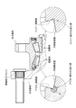
- FIG. 7 is a cross-sectional view showing the inner-side crushed portion 8 and its periphery.
- FIG. 7 corresponds to an enlarged view of region B in FIG.
- the inner ring 32 is formed with an inner side flange surface 3m substantially perpendicular to the inner rolling surface 3d.
- the inner side flange surface 3m is formed in an arc shape with an axial cross section having a radius of curvature r1. Further, the inner side flange surface 3m has an outer end portion in an axial cross section formed in an arc shape having a curvature radius r2, and is smoothly connected to the fitting surface 3g.
- the tapered roller 4 has a large-diameter side end surface 4b formed in a spherical shape having a curvature radius r3.
- the large-diameter side end face 4b and the inner side flange face 3m come into contact at a point P in the drawing. If it demonstrates in detail, the large diameter side end surface 4b and the inner side collar surface 3m will contact in the elliptical surface centering on the point P in a figure. However, the size of the ellipsoid varies depending on the load applied in the axial direction.
- an inner side crushed portion 8 that is recessed in a substantially arc shape is formed at a portion where the inner rolling surface 3 d and the inner side flange surface 3 m intersect.
- the inner peripheral surface 8a is connected to the inner raceway surface 3d through a gentle curved surface 8b.
- the inner peripheral surface 8a of the inner-side crushed portion 8 is connected to the inner-side flange surface 3m via a gentle curved surface 8c.
- the inner-side crushed portion 8 is formed to be relatively large so as to include the chamfered portion 4 d of the tapered roller 4.
- the inner peripheral surface 8a of the inner-side crushed portion 8 has a substantially arc shape.
- the curvature radius of the substantially arc shape is defined as “curvature radius Ri”.
- the height dimension of the portion where the large diameter side end face 4b of the tapered roller 4 is in contact with the inner side flange face 3m is defined as “height dimension Di”.
- the height dimension of the portion formed in the arc shape of the curvature radius r1 in the inner side flange surface 3m is defined as “height dimension Di”.
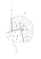
- FIG. 8 is a cross-sectional view showing the outer-side crushed portion 9 and its periphery.
- FIG. 8 corresponds to an enlarged view of region C in FIG.
- the outer ring surface 3n is formed on the hub wheel 31 in a direction substantially perpendicular to the inner rolling surface 3c.
- the outer side flange surface 3n is formed in an arc shape having a radius of curvature r1 in its axial cross section. Further, the outer side flange surface 3n has an outer end portion in an axial cross section formed in an arc shape having a curvature radius r2, and is smoothly connected to the inclined surface 3p.
- the tapered roller 4 has a large-diameter side end surface 4b formed in a spherical shape having a curvature radius r3.
- the large-diameter side end face 4b and the inner side flange face 3n come into contact at a point P in the drawing. If it demonstrates in detail, the large diameter side end surface 4b and the inner side collar surface 3n will contact in the elliptical surface centering on the point P in a figure. However, the size of the ellipsoid varies depending on the load applied in the axial direction.
- the outer side nuisance processing part 9 recessed in the substantially arc shape is formed in the part where the inner side rolling surface 3c and the inner side flange surface 3n intersect.
- the outer peripheral surface 9a has an inner peripheral surface 9a connected to the inner rolling surface 3c via a gently curved surface 9b.
- the outer peripheral side processed part 9 has the inner peripheral surface 9a connected to the outer side flange surface 3n through a gentle curved surface 9c.
- the outer-side crushed portion 9 is formed to be relatively large so as to include the chamfered portion 4 d of the tapered roller 4.
- the inner peripheral surface 9a of the outer side nuisance processing portion 9 has a substantially arc shape.
- the curvature radius of the substantially arc shape is defined as “curvature radius Ro”.
- the height dimension of the part which the large diameter side end surface 4b and the outer side collar surface 3n of the tapered roller 4 contact is defined as "height dimension Do”.
- a height dimension of a portion formed in an arc shape having a radius of curvature r1 on the outer side flange surface 3n is defined as a “height dimension Do”.
- the inner peripheral surface 8a of the inner-side crushed portion 8 has a substantially arc shape.
- the curvature radius Ri is 1.0 mm.
- the inner peripheral surface 9a of the outer side blank processing portion 9 has a substantially arc shape.
- the curvature radius Ro is 2.0 mm. This is based on the result that it is necessary to satisfy Ri ⁇ Ro and it is preferable to satisfy 1.2 ⁇ Ri ⁇ Ro ⁇ 2.5 ⁇ Ri by numerical analysis using all conditions as parameters. In addition, by satisfying Ri ⁇ Ro, it is possible to prevent stress from being concentrated on the outer-side crushed portion 9.
- the radius of curvature of the inner-side crushed portion 8 is Ri and the radius of curvature of the outer-side crushed portion 9 is Ro, these are 1.2 ⁇ Ri ⁇ Ro ⁇ 2.
- the relationship of 5 ⁇ Ri is satisfied. According to such a wheel bearing device 1, even when an external force is applied to the wheel mounting flange 3 e, it is difficult to cause a distortion that causes the outer side blanking portion 9 to open and close. Accordingly, it is possible to reliably reduce the stress value generated in the outer-side crushed portion 9.
- the wheel bearing device 1 is configured such that the height dimension of the portion where the large diameter side end surface 4b of the tapered roller 4 is in contact with the inner side flange surface 3m is Di, and the outer side flange is connected to the large diameter side end surface 4b of the tapered roller 4.
- Di Do.
Landscapes
- Engineering & Computer Science (AREA)
- General Engineering & Computer Science (AREA)
- Mechanical Engineering (AREA)
- Rolling Contact Bearings (AREA)
Abstract
内方部材(3)のインナー側に形成された内側転走面(3d)と内側転走面(3d)のインナー側鍔面(3m)が交わる部分にインナー側ヌスミ加工部(8)が設けられ、内方部材(3)のアウター側に形成された内側転走面(3c)と内側転走面(3c)のアウター側鍔面(3n)が交わる部分にアウター側ヌスミ加工部(9)が設けられ、更に内方部材(3)のアウター側に形成された内側転走面(3c)の隣接箇所に車輪取付フランジ(3e)が設けられている車輪用軸受装置(1)において、インナー側ヌスミ加工部(8)の曲率半径をRiとし、アウター側ヌスミ加工部(9)の曲率半径をRoとした場合、これらがRi<Roの関係を満たしている、とした。
Description
本発明は、車輪用軸受装置に関する。
従来より、車輪を回転自在に支持する車輪用軸受装置が知られている(例えば特許文献1参照)。かかる車輪用軸受装置は、車体に外方部材が固定される。また、外方部材の内側に内方部材が配置され、外方部材と内方部材のそれぞれの転走面間に複数の転動体が介装されている。こうして、車輪用軸受装置は、転がり軸受構造を構成し、内方部材に取り付けられた車輪を回転自在としているのである。
ところで、このような車輪用軸受装置は、内方部材のインナー側に形成された内側転走面と当該内側転走面のインナー側鍔面が交わる部分に、いわゆるヌスミ加工が施されている(以降「インナー側ヌスミ加工部」という:図9参照)。また、内方部材のアウター側に形成された内側転走面と当該内側転走面のアウター側鍔面が交わる部分にも、いわゆるヌスミ加工が施されている(以降「アウター側ヌスミ加工部」という:図9参照)。インナー側ヌスミ加工部およびアウター側ヌスミ加工部は、切削工具の刃先を逃がすために形成された窪み部分である。
更に、このような車輪用軸受装置は、内方部材のアウター側に形成された内側転走面の隣接箇所に車輪取付フランジが設けられている。そのため、車輪が縁石に乗り上げるなどして車輪取付フランジに大きくかつ衝撃的な外力が掛かると、車輪取付フランジの基端部分に近いアウター側ヌスミ加工部に応力が集中してしまう場合があった(図9における※印部参照)。そこで、内方部材のアウター側にはアウター側鍔面を形成せず、別部材を嵌合することによってアウター側鍔面の機能を確保した車輪用軸受装置が提案されていたのである(例えば特許文献2参照)。しかし、かかる車輪用軸受装置は、切削加工に時間がかかるとともに部品点数が多く、更には構造が複雑になるという問題があった。このような背景から、簡素な構造でありながらアウター側ヌスミ加工部に生じる応力値を低減できる車輪用軸受装置が求められていたのである。ひいては、簡素な構造でありながら高い剛性を確保できる車輪用軸受装置が求められていたのである。
簡素な構造でありながらアウター側ヌスミ加工部に生じる応力値を低減できる車輪用軸受装置を提供する。ひいては、簡素な構造でありながら高い剛性を確保できる車輪用軸受装置を提供する。
第一の発明は、
内周に複列の外側転走面が形成された外方部材と、
外周に複列の内側転走面が形成された内方部材と、
前記外方部材と前記内方部材のそれぞれの転走面間に転動自在に介装される複数の転動体と、を備え、
前記内方部材のインナー側に形成された前記内側転走面と当該内側転走面のインナー側鍔面が交わる部分にインナー側ヌスミ加工部が設けられ、
前記内方部材のアウター側に形成された前記内側転走面と当該内側転走面のアウター側鍔面が交わる部分にアウター側ヌスミ加工部が設けられ、
更に前記内方部材のアウター側に形成された前記内側転走面の隣接箇所に車輪取付フランジが設けられている車輪用軸受装置において、
前記インナー側ヌスミ加工部の曲率半径をRiとし、
前記アウター側ヌスミ加工部の曲率半径をRoとした場合、
これらがRi<Roの関係を満たしている、としたものである。
内周に複列の外側転走面が形成された外方部材と、
外周に複列の内側転走面が形成された内方部材と、
前記外方部材と前記内方部材のそれぞれの転走面間に転動自在に介装される複数の転動体と、を備え、
前記内方部材のインナー側に形成された前記内側転走面と当該内側転走面のインナー側鍔面が交わる部分にインナー側ヌスミ加工部が設けられ、
前記内方部材のアウター側に形成された前記内側転走面と当該内側転走面のアウター側鍔面が交わる部分にアウター側ヌスミ加工部が設けられ、
更に前記内方部材のアウター側に形成された前記内側転走面の隣接箇所に車輪取付フランジが設けられている車輪用軸受装置において、
前記インナー側ヌスミ加工部の曲率半径をRiとし、
前記アウター側ヌスミ加工部の曲率半径をRoとした場合、
これらがRi<Roの関係を満たしている、としたものである。
第二の発明は、第一の発明に係る車輪用軸受装置において、
前記インナー側ヌスミ加工部の曲率半径をRiとし、
前記アウター側ヌスミ加工部の曲率半径をRoとした場合、
これらが1.2×Ri<Ro<2.5×Riの関係を満たしている、としたものである。
前記インナー側ヌスミ加工部の曲率半径をRiとし、
前記アウター側ヌスミ加工部の曲率半径をRoとした場合、
これらが1.2×Ri<Ro<2.5×Riの関係を満たしている、としたものである。
第三の発明は、第一又は第二の発明に係る車輪用軸受装置において、
前記転動体の大径側端面と前記インナー側鍔面が接する部分の高さ寸法をDiとし、
前記転動体の大径側端面と前記アウター側鍔面が接する部分の高さ寸法をDoとした場合、
これらがDi=Doの関係を満たしている、としたものである。
前記転動体の大径側端面と前記インナー側鍔面が接する部分の高さ寸法をDiとし、
前記転動体の大径側端面と前記アウター側鍔面が接する部分の高さ寸法をDoとした場合、
これらがDi=Doの関係を満たしている、としたものである。
第一の発明に係る車輪用軸受装置は、インナー側ヌスミ加工部の曲率半径をRiとし、アウター側ヌスミ加工部の曲率半径をRoとした場合、これらがRi<Roの関係を満たしている。かかる車輪用軸受装置によれば、アウター側ヌスミ加工部に応力が集中するのを防ぐことができる。従って、簡素な構造でありながらアウター側ヌスミ加工部に生じる応力値を低減することができる。ひいては、簡素な構造でありながら高い剛性を確保することができる。
第二の発明に係る車輪用軸受装置は、インナー側ヌスミ加工部の曲率半径をRiとし、アウター側ヌスミ加工部の曲率半径をRoとした場合、これらが1.2×Ri<Ro<2.5×Riの関係を満たしている。かかる車輪用軸受装置によれば、車輪取付フランジに外力が掛かってもアウター側ヌスミ加工部が開閉するような歪みが生じにくくなる。従って、アウター側ヌスミ加工部に生じる応力値を確実に低減することができる。
第三の発明に係る車輪用軸受装置は、転動体の大径側端面とインナー側鍔面が接する部分の高さ寸法をDiとし、転動体の大径側端面とアウター側鍔面が接する部分の高さ寸法をDoとした場合、これらがDi=Doの関係を満たしている。かかる車輪用軸受装置によれば、車輪取付フランジに外力が掛かってもアウター側ヌスミ加工部が開閉するような歪みが生じにくくなる。従って、アウター側ヌスミ加工部に生じる応力値を更に確実に低減することができる。
まず、図1から図4を用いて、本発明に係る車輪用軸受装置1について説明する。図1は、車輪用軸受装置1を示す斜視図である。図2は、車輪用軸受装置1の構造を示す断面図である。図3および図4は、車輪用軸受装置1の一部構造を示す断面図である。
車輪用軸受装置1は、車輪を回転自在に支持するものである。車輪用軸受装置1は、外方部材2と、内方部材3と、転動体4と、保持器5と、インナー側シール部材6と、アウター側シール部材7と、を備える。なお、本明細書において、「インナー側」とは、車体に取り付けた際の車輪用軸受装置1の車体側を表し、「アウター側」とは、車体に取り付けた際の車輪用軸受装置1の車輪側を表す。
外方部材2は、転がり軸受構造の外輪部分を構成するものである。外方部材2は、例えばS53C等の中高炭素鋼で構成されている。外方部材2のインナー側端部における内周には、嵌合面2aが形成されている。また、外方部材2のアウター側端部における外周には、嵌合面2bが形成されている。更に、外方部材2の軸方向中央部における内周には、二つの外側転走面2c・2dが形成されている。外側転走面2cは、後述する内側転走面3cに対向する。外側転走面2dは、後述する内側転走面3dに対向する。なお、外側転走面2c・2dには、例えば高周波焼入れが施され、表面硬度が58~64HRCの範囲となっている。加えて、外方部材2の外周には、車体取付フランジ2eが一体的に形成されている。車体取付フランジ2eには、複数のボルト穴2fが設けられている。
内方部材3は、転がり軸受構造の内輪部分を構成するものである。内方部材3は、ハブ輪31と内輪32で構成されている。
ハブ輪31は、例えばS53C等の中高炭素鋼で構成されている。ハブ輪31には、そのインナー側端部から軸方向中央部まで小径段部3aが形成されている。小径段部3aは、ハブ輪31の外径が小さくなった部分を指し、その外周面が回転軸Aを中心とする円筒形状となっている。また、ハブ輪31には、そのインナー側端部からアウター側端部まで貫かれた自在継手取付穴3bが形成されている。自在継手取付穴3bは、ハブ輪31の中心に設けられた貫通穴を指し、その内周面が凹部と凸部が交互に並ぶ凹凸形状(スプライン穴)となっている。但し、従動仕様については、自在継手取付穴3bが形成されていない。更に、ハブ輪31の外周には、内側転走面3cが形成されている。内側転走面3cは、前述した外側転走面2cに対向する。なお、小径段部3aから内側転走面3cを経てシールランド部(後述する車輪取付フランジ3eの基端部分である)までには、例えば高周波焼入れが施され、表面硬度が58~64HRCの範囲となっている。加えて、ハブ輪31の外周には、車輪取付フランジ3eが一体的に形成されている。車輪取付フランジ3eには、回転軸Aを中心とする同心円上に等間隔で複数のボルト穴3fが設けられ、それぞれのボルト穴3fにはハブボルト33が圧入されている。
内輪32は、例えばSUJ2等の高炭素クロム軸受鋼で構成されている。内輪32の外周には、嵌合面3gが形成されている。また、内輪32の外周には、内側転走面3dが形成されている。内輪32は、ハブ輪31の小径段部3aに嵌合(外嵌)されることにより、ハブ輪31の外周に内側転走面3dを構成する。内側転走面3dは、前述した内側転走面2dに対向する。なお、内輪32は、いわゆるズブ焼入れが施され、芯部まで58~64HRCの範囲となっている。
転動体(以降「円錐ころ」という)4は、転がり軸受構造の転動部分を構成するものである。円錐ころ4は、例えばSUJ2等の高炭素クロム軸受鋼若しくはSCr420等の浸炭鋼で構成されている。インナー側の円錐ころ列4Rを構成している円錐ころ4は、後述する保持器5によって円形にかつ等間隔にならべられている。これらの円錐ころ4は、外方部材2の外側転走面2dと内方部材3(内輪32)の内側転走面3dの間に転動自在に介装されている。また、アウター側の円錐ころ列4Rを構成している円錐ころ4も、後述する保持器5によって円形にかつ等間隔にならべられている。これらの円錐ころ4は、外方部材2の外側転走面2cと内方部材3(ハブ輪31)の内側転走面3cの間に転動自在に介装されている。なお、円錐ころ4は、いわゆるズブ焼入れが施され、芯部まで62~67HRCの範囲となっている。
保持器5は、円錐ころ4の偏動を制限するものである。保持器5は、例えばPA66等のエンジニアリングプラスチック若しくはPPS等のスーパーエンジニアリングプラスチック、あるいはこれらにグラスファイバー等を含有させたもので構成されている。保持器5は、小径円環部5aと大径円環部5bを複数の柱部5cでつないだテーパ形状の格子体となっている。小径円環部5aは、円錐ころ4の小径側端面4aに沿うので、円錐ころ4の軸方向一側への偏動(図3および図4における矢印X方向へのズレ)を制限する。また、大径円環部5bは、円錐ころ4の大径側端面4bに沿うので、円錐ころ4の軸方向他側への偏動(図3および図4における矢印Y方向へのズレ)を制限する。そして、柱部5cは、互いに隣り合う円錐ころ4と円錐ころ4の間を通り、これらの外周面4cに沿うので、円錐ころ4の周方向への偏動を制限する。なお、保持器5は、フェノール樹脂やエポキシ樹脂、ポリアミド樹脂等にカーボンファイバー等を含有させたもので構成されていてもよい。また、冷間圧延鋼板や熱間圧延鋼板、あるいはオーステナイト系ステンレス鋼板で構成されていてもよい。
インナー側シール部材6は、外方部材2と内方部材3の間に形成された環状空間Sのインナー側開口端を密封するものである。但し、インナー側シール部材6については、様々な仕様が存在しており、本願の仕様に限定するものではない。また、インナー側シール部材6の代わりにキャップが取り付けられる仕様や何も取り付けられない仕様も存在する。
インナー側シール部材6は、スリンガ61を含んでいる。スリンガ61は、内輪32の嵌合面3gに嵌合(外嵌)される。スリンガ61は、例えばSUS430やSUS304等のステンレス鋼板、あるいはSPCC等の冷間圧延鋼板で構成されている。スリンガ61は、円環状の鋼板がプレス加工によって変形され、軸方向断面が略L字状に折り曲げられた形状となっている。これにより、スリンガ61は、円筒状の嵌合部61aと、その端部から外方部材2に向かって延びる円板状の側板部61bと、が形成されている。
インナー側シール部材6は、シールリング62を含んでいる。シールリング62は、外方部材2の嵌合部2aに嵌合(内嵌)される。シールリング62は、芯金63とシールゴム64で構成されている。芯金63は、例えばSUS430やSUS304等のステンレス鋼板、あるいはSPCC等の冷間圧延鋼板で構成されている。芯金63は、円環状の鋼板がプレス加工によって変形され、軸方向断面が略L字状に折り曲げられた形状となっている。これにより、芯金63は、円筒状の嵌合部63aと、その端部から内輪32に向かって延びる円板状の側板部63bと、が形成されている。なお、嵌合部63aと側板部63bには、弾性体であるシールゴム64が加硫接着されている。
シールゴム64は、例えばNBR(アクリロニトリル-ブタジエンゴム)、HNBR(水素化アクリロニトリル・ブタジエンゴム)、EPDM(エチレンプロピレンゴム)、ACM(ポリアクリルゴム)、FKM(フッ素ゴム)、あるいはシリコンゴム等の合成ゴムで構成されている。シールゴム64に形成されたシールリップ64a・64bは、いわゆるメインリップであって、その先端縁がスリンガ61の側板部61bに接触している。また、シールリップ64cは、いわゆるグリースリップであって、その先端縁がスリンガ61の嵌合部61aに接触している。このようにして、インナー側シール部材6は、泥水や砂塵等の異物が環状空間Sに侵入するのを防ぐとともに、グリースが環状空間Sから漏出するのを防いでいる。
アウター側シール部材7は、外方部材2と内方部材3の間に形成された環状空間Sのアウター側開口端を密封するものである。但し、アウター側シール部材7については、様々な仕様が存在しており、本願の仕様に限定するものではない。
アウター側シール部材7は、外方部材2の嵌合面2bに嵌合(外嵌)される。アウター側シール部材7は、芯金72とシールゴム73で構成されている。芯金72は、例えばSUS430やSUS304等のステンレス鋼板、あるいはSPCC等の冷間圧延鋼板で構成されている。芯金72は、円環状の鋼板がプレス加工によって変形され、軸方向断面が略L字状に折り曲げられた形状となっている。これにより、芯金72は、円筒状の嵌合部72aと、その端部からハブ輪31に向かって延びる円板状の側板部72bと、が形成されている。なお、嵌合部72aと側板部72bには、弾性体であるシールゴム73が加硫接着されている。
シールゴム73は、例えばNBR(アクリロニトリル-ブタジエンゴム)、HNBR(水素化アクリロニトリル・ブタジエンゴム)、EPDM(エチレンプロピレンゴム)、ACM(ポリアクリルゴム)、FKM(フッ素ゴム)、あるいはシリコンゴム等の合成ゴムで構成されている。シールゴム73に形成されたシールリップ73a・73bは、いわゆるメインリップであって、その先端縁が車輪取付フランジ3eのシール平面部3hに接触している。また、シールリップ73cは、いわゆるグリースリップであって、その先端縁が車輪取付フランジ3eに形成された段差部3iのシール周面部3jに接触している。このようにして、アウター側シール部材7は、泥水や砂塵等の異物が環状空間Sに侵入するのを防ぐとともに、グリースが環状空間Sから漏出するのを防いでいるのである。
ここで、図5を用いて、アウター側シール部材7について詳細に説明する。図5は、アウター側シール部材7を示す断面図である。以下において、「外方側」とは、「径方向外側」とほぼ同義であって、内方部材3の回転軸Aから遠ざかる方向を表す。また、「内方側」とは、「径方向内側」とほぼ同義であって、内方部材3の回転軸Aに近づく方向を表す。
アウター側シール部材7において、芯金72は、円筒状の嵌合部72aを有しており、この嵌合部72aが外方部材2の嵌合面2bに嵌合(外嵌)される。このとき、外方部材2は、外側転走面2cからアウター側端面2hまでの距離が短く設計されているため、嵌合部72aは、アウター側の円錐ころ列4Rを構成している保持器5の外方側に嵌合される。なお、従来品に係る車輪用軸受装置と異なり、外側転走面2cからアウター側端面2hまでの距離を短く設計できるのは、外方部材2の内側にアウター側シール部材7を収容する必要がないためである。
加えて、芯金72は、円板状の側板部72bを有しており、この側板部72bが外方部材2のアウター側端面2hに沿って延びている。このとき、外方部材2は、外側転走面2cからアウター側端面2hまでの距離が短く設計されているため、側板部72bは、アウター側の円錐ころ列4Rを構成している保持器5のアウター側端部近傍に向けて延びている。より詳細には、保持器5の大径円環部5b近傍に向けて延びている。ここで、「保持器5のアウター側端部近傍に向けて」や「保持器5の大径円環部5b近傍に向けて」は、内方側へ延びる側板部72bの大まかな方向を表すものである。これは、外方部材2のアウター側端面2hに沿う側板部72bが、そのまま保持器5の大径円環部5b近傍に向けて延びているのを表すことで、外方部材2のアウター側端面2hと保持器5の大径円環部5bが同一平面若しくは略同一平面となっていることを表している。本車輪用軸受装置1においては、外方部材2のアウター側端面2hが保持器5の大径円環部5bよりも僅かにアウター側に形成された関係となっている。
更に、アウター側シール部材7において、シールゴム73は、シールリップ73aを有しており、このシールリップ73aはインナー側からアウター側へ向かうにつれて外方側へ傾くように延びている。そして、シールリップ73aの先端縁が車輪取付フランジ3eのシール平面部3hに接触している。なお、シールリップ73aは、いわゆるメインリップであり、外部から環状空間Sへ向かう方向に対して締付力が高まるので、主に泥水や砂塵等の異物が環状空間Sに侵入するのを防ぐ機能を果たしている。
加えて、シールゴム73は、シールリップ73bを有しており、このシールリップ73bもインナー側からアウター側へ向かうにつれて外方側へ傾くように延びている。そして、シールリップ73bの先端縁が同じくシール平面部3hに接触している。なお、シールリップ73bも、いわゆるメインリップであり、外部から環状空間Sへ向かう方向に対して締付力が高まるので、主に泥水や砂塵等の異物が環状空間Sに侵入するのを防ぐ機能を果たしている。
加えて、シールゴム73は、シールリップ73cを有しており、このシールリップ73cはアウター側へ向かった後に折り返された形状とされ、アウター側からインナー側へ向かうにつれて内方側へ傾くように延びている。そして、シールリップ73cの先端縁が段差部3iのシール周面部3jに接触している。なお、シールリップ73cは、いわゆるグリースリップであり、環状空間Sから外部へ向かう方向に対して締付力が高まるので、主にグリースが環状空間Sから漏出するのを防ぐ機能を果たしている。
このように、本車輪用軸受装置1は、アウター側シール部材7が外方部材2の外周面に嵌合される芯金72と芯金72に加硫接着されたシールゴム73で構成されている。そして、芯金72が外方部材2のアウター側端面2hに沿って保持器5のアウター側端部近傍(大径円環部5b近傍)に向けて延びており、更にシールゴム73に形成された全てのシールリップ73a・73b・73cが外方部材2のアウター側端面2hよりもアウター側に配置されている。かかる車輪用軸受装置1によれば、外方部材2の内側にアウター側シール部材7を収容するためのスペースを確保する必要がなくなり、全てのシールリップ73a・73b・73cが径方向に並んで配置されるので、軸方向長さを短縮できる。ひいては、同じ外力が掛かっても曲げモーメントが小さくなるので、軸受剛性を向上でき、更に軽量化を実現することができる。
また、本車輪用軸受装置1において、シールリップ73a・73bであるメインリップは、インナー側からアウター側へ向かうにつれて外方側へ傾く形状とされ、その先端縁が内方部材3に形成された車輪取付フランジ3eのシール平面部3hに接触している。かかる車輪用軸受装置1によれば、全てのメインリップ(73a・73b)が同一平面(3h)に接触するので、それぞれのメインリップ(73a・73b)の接触圧力が内方部材3の製品誤差や組立誤差に起因してバラツクことを抑えることができる。
更に、本車輪用軸受装置1においては、車輪取付フランジ3eにアウター側シール部材7の内方側まで突出した段差部3iが形成されており、シールリップ73cであるグリースリップは、アウター側からインナー側へ向かうにつれて内方側へ傾く形状とされ、その先端縁が段差部3iのシール周面部3jに接触している。かかる車輪用軸受装置1によれば、段差部3iが環状空間Sのアウター側開口端を狭めてグリースの移動を制限するので、転動体4および転動面(外側転走面2c・内側転走面3c)の油膜切れを防ぐことができる。また、グリースの漏出を低減させることもできる。
加えて、本車輪用軸受装置1において、芯金72は、嵌合部72aの一端から円弧状に折り返されており、この折返部分72dを覆うようにシールゴム73が加硫接着されている。そして、嵌合面2bに接する部分におけるシールゴム73には、内方側へ突出する第一締代部73dが設けられている。このようにすることで、外方部材2と芯金72の嵌合部分に対して一方から水分が浸入するのを防ぐことができる。ひいては、外方部材2と芯金72の嵌合部分が腐食するのを防ぐことができる。
加えて、本車輪用軸受装置1において、芯金72は、側板部72bの先端部分72eがアウター側端面2hから離間するように曲げられており、この先端部分72eを覆うようにシールゴム73が加硫接着されている。そして、アウター側端面2hに接する部分におけるシールゴム73には、インナー側へ突出する第二締代部73eが設けられている。このようにすることで、外方部材2と芯金72の嵌合部分に対して他方から水分が浸入するのを防ぐことができる。ひいては、外方部材2と芯金72の嵌合部分が腐食するのを防ぐことができる。
加えて、本車輪用軸受装置1において、芯金72は、嵌合部72aの一端からアウター側へ折り返されるとともに、その末端が外方側へ折り曲げられており、この折返部分72dと折曲部分72fを覆うようにシールゴム73が加硫接着されている。こうして、アウター側シール部材7には、外方側へ突出した堰部74が形成されている。堰部74は、外方部材2を伝って流れる泥水や車体から流れ落ちた泥水等がシールリップ73a・73b・73cまで到達するのを低減している。
加えて、本車輪用軸受装置1において、シールゴム73は、ラビリンスリップ73fを有しており、このラビリンスリップ73fはインナー側からアウター側へ向かうにつれて外方側へ傾くように延びている。そして、ラビリンスリップ73fは、シール平面部3hの傾斜面3kに対して小さな隙間をあけて沿っている。従って、堰部74は、外方部材2を伝って流れる泥水や車体から流れ落ちた泥水等がシールリップ73a・73b・73cまで到達するのを更に低減している。
次に、図6を用いて、車輪用軸受装置1を車体に取り付けるための構造について説明する。図6は、車輪用軸受装置1の取付構造を示す断面図である。図中の矢印Mは、車輪が縁石に乗り上げるなどした場合に、車輪取付フランジ3eに生じる曲げモーメントを示したものである。
車輪用軸受装置1は、パイロット2gと車体取付フランジ2eを用いて車体に取り付けられる。具体的に説明すると、車輪用軸受装置1は、円筒形状であるパイロット2gをナックルNの丸円に嵌め合わせるとともに、車体取付フランジ2eの端面をナックルNの端面に当接させた状態で、ナックルボルト34を介して取り付けられる。このとき、ナックルボルト34は、車体取付フランジ2eのボルト穴2fにアウター側から挿通され、ナックルNのボルト穴Nhに螺合される。あるいは、ナックルNのボルト穴Nhにインナー側から挿通され、車体取付フランジ2eのボルト穴2fに螺合される。
次に、図7を用いて、インナー側ヌスミ加工部8について詳細に説明する。図7は、インナー側ヌスミ加工部8とその周辺を示す断面図である。図7は、図6における領域Bを拡大した図に相当する。
図7に示すように、内輪32には、内側転走面3dに対して略垂直方向にインナー側鍔面3mが形成されている。インナー側鍔面3mは、その軸方向断面が曲率半径r1の円弧状に形成されている。また、インナー側鍔面3mは、その軸方向断面の外端部分が曲率半径r2の円弧状に形成されており、滑らかに嵌合面3gにつながっている。一方で、円錐ころ4は、その大径側端面4bが曲率半径r3の球面状に形成されている。従って、大径側端面4bとインナー側鍔面3mは、図中の点Pにて接触することとなる。より詳細に説明すると、大径側端面4bとインナー側鍔面3mは、図中の点Pを中心とする楕円面にて接触することとなる。但し、かかる楕円面の大きさは、軸方向へ掛かる荷重の大きさによって変化するものである。
更に、図7に示すように、内側転走面3dとインナー側鍔面3mが交わる部分には、略円弧形状に窪んだインナー側ヌスミ加工部8が形成されている。インナー側ヌスミ加工部8は、その内周面8aが緩やかな曲面8bを介して内側転走面3dにつながっている。また、インナー側ヌスミ加工部8は、その内周面8aが緩やかな曲面8cを介してインナー側鍔面3mにつながっている。そして、インナー側ヌスミ加工部8は、円錐ころ4の面取部4dを包含するように比較的に大きく形成されている。なお、本車輪用軸受装置1において、インナー側ヌスミ加工部8は、その内周面8aが略円弧形状となっている。本願においては、かかる略円弧形状の曲率半径を「曲率半径Ri」と定義している。また、本願においては、円錐ころ4の大径側端面4bとインナー側鍔面3mが接する部分の高さ寸法を「高さ寸法Di」と定義している。具体的には、インナー側鍔面3mのうち曲率半径r1の円弧状に形成されている部分の高さ寸法を「高さ寸法Di」と定義している。
次に、図8を用いて、アウター側ヌスミ加工部9について詳細に説明する。図8は、アウター側ヌスミ加工部9とその周辺を示す断面図である。図8は、図6における領域Cを拡大した図に相当する。
図8に示すように、ハブ輪31には、内側転走面3cに対して略垂直方向にアウター側鍔面3nが形成されている。アウター側鍔面3nは、その軸方向断面が曲率半径r1の円弧状に形成されている。また、アウター側鍔面3nは、その軸方向断面の外端部分が曲率半径r2の円弧状に形成されており、滑らかに傾斜面3pにつながっている。一方で、円錐ころ4は、その大径側端面4bが曲率半径r3の球面状に形成されている。従って、大径側端面4bとインナー側鍔面3nは、図中の点Pにて接触することとなる。より詳細に説明すると、大径側端面4bとインナー側鍔面3nは、図中の点Pを中心とする楕円面にて接触することとなる。但し、かかる楕円面の大きさは、軸方向へ掛かる荷重の大きさによって変化するものである。
更に、図8に示すように、内側転走面3cとインナー側鍔面3nが交わる部分には、略円弧形状に窪んだアウター側ヌスミ加工部9が形成されている。アウター側ヌスミ加工部9は、その内周面9aが緩やかな曲面9bを介して内側転走面3cにつながっている。また、アウター側ヌスミ加工部9は、その内周面9aが緩やかな曲面9cを介してアウター側鍔面3nにつながっている。そして、アウター側ヌスミ加工部9は、円錐ころ4の面取部4dを包含するように比較的に大きく形成されている。なお、本車輪用軸受装置1において、アウター側ヌスミ加工部9は、その内周面9aが略円弧形状となっている。本願においては、かかる略円弧形状の曲率半径を「曲率半径Ro」と定義している。また、本願においては、円錐ころ4の大径側端面4bとアウター側鍔面3nが接する部分の高さ寸法を「高さ寸法Do」と定義している。具体的には、アウター側鍔面3nのうち曲率半径r1の円弧状に形成されている部分の高さ寸法を「高さ寸法Do」と定義している。
以下に、曲率半径Riと曲率半径Roの関係について説明する。また、高さ寸法Diと高さ寸法Doの関係についても説明する。
上述したように、インナー側ヌスミ加工部8は、その内周面8aが略円弧形状となっている。そして、本車輪用軸受装置1においては、その曲率半径Riが1.0mmとなっている。一方で、アウター側ヌスミ加工部9も、その内周面9aが略円弧形状となっている。そして、本車輪用軸受装置1においては、その曲率半径Roが2.0mmとなっている。これは、あらゆる条件をパラメータとした数値解析により、Ri<Roを満たす必要があり、かつ1.2×Ri<Ro<2.5×Riを満たすことが好ましいとの結果に基づくものである。なお、Ri<Roを満たすことにより、アウター側ヌスミ加工部9に応力が集中するのを防ぐことができる。また、1.2×Ri<Ro<2.5×Riを満たすことにより、車輪取付フランジ3eに外力が掛かってもアウター側ヌスミ加工部9が開閉するような歪みが生じにくくなる。なお、1.2×Ri<Ro<2.5×Riを満たすことで、応力値が5%~20%低減するという顕著な効果を奏する。
加えて、同様の数値解析により、Di=Doを満たすことがより好ましいとの結果も得られている。Di=Doを満たすことにより、車輪取付フランジ3eに外力が掛かってもアウター側ヌスミ加工部9が開閉するような歪みが生じにくくなるからである。
このように、本車輪用軸受装置1は、インナー側ヌスミ加工部8の曲率半径をRiとし、アウター側ヌスミ加工部9の曲率半径をRoとした場合、これらがRi<Roの関係を満たしている。かかる車輪用軸受装置1によれば、アウター側ヌスミ加工部9に応力が集中するのを防ぐことができる。従って、簡素な構造でありながらアウター側ヌスミ加工部9に生じる応力値を低減することができる。ひいては、簡素な構造でありながら高い剛性を確保することができる。
また、本車輪用軸受装置1は、インナー側ヌスミ加工部8の曲率半径をRiとし、アウター側ヌスミ加工部9の曲率半径をRoとした場合、これらが1.2×Ri<Ro<2.5×Riの関係を満たしている。かかる車輪用軸受装置1によれば、車輪取付フランジ3eに外力が掛かってもアウター側ヌスミ加工部9が開閉するような歪みが生じにくくなる。従って、アウター側ヌスミ加工部9に生じる応力値を確実に低減することができる。
更に、本車輪用軸受装置1は、円錐ころ4の大径側端面4bとインナー側鍔面3mが接する部分の高さ寸法をDiとし、円錐ころ4の大径側端面4bとにアウター側鍔面3nが接する部分の高さ寸法をDoとした場合、これらがDi=Doの関係を満たしている。かかる車輪用軸受装置1によれば、車輪取付フランジ3eに外力が掛かってもアウター側ヌスミ加工部9が開閉するような歪みが生じにくくなる。従って、アウター側ヌスミ加工部9に生じる応力値を更に確実に低減することができる。
1 車輪用軸受装置
2 外方部材
2c 外側転走面
2d 外側転走面
3 内方部材
3c 内側転走面
3d 内側転走面
3e 車輪取付フランジ
3m インナー側鍔面
3n アウター側鍔面
4 転動体
4a 小径側端面
4b 大径側端面
4c 外周面
5 保持器
6 インナー側シール部材
7 アウター側シール部材
8 インナー側ヌスミ加工部
8a 内周面
8b 曲面
8c 曲面
9 アウター側ヌスミ加工部
9a 内周面
9b 曲面
9c 曲面
Ri インナー側ヌスミ加工部の曲率半径
Ro アウター側ヌスミ加工部の曲率半径
Di 転動体の大径側端面とインナー側鍔面が接する部分の高さ寸法
Do 転動体の大径側端面とアウター側鍔面が接する部分の高さ寸法
2 外方部材
2c 外側転走面
2d 外側転走面
3 内方部材
3c 内側転走面
3d 内側転走面
3e 車輪取付フランジ
3m インナー側鍔面
3n アウター側鍔面
4 転動体
4a 小径側端面
4b 大径側端面
4c 外周面
5 保持器
6 インナー側シール部材
7 アウター側シール部材
8 インナー側ヌスミ加工部
8a 内周面
8b 曲面
8c 曲面
9 アウター側ヌスミ加工部
9a 内周面
9b 曲面
9c 曲面
Ri インナー側ヌスミ加工部の曲率半径
Ro アウター側ヌスミ加工部の曲率半径
Di 転動体の大径側端面とインナー側鍔面が接する部分の高さ寸法
Do 転動体の大径側端面とアウター側鍔面が接する部分の高さ寸法
Claims (3)
- 内周に複列の外側転走面が形成された外方部材と、
外周に複列の内側転走面が形成された内方部材と、
前記外方部材と前記内方部材のそれぞれの転走面間に転動自在に介装される複数の転動体と、を備え、
前記内方部材のインナー側に形成された前記内側転走面と当該内側転走面のインナー側鍔面が交わる部分にインナー側ヌスミ加工部が設けられ、
前記内方部材のアウター側に形成された前記内側転走面と当該内側転走面のアウター側鍔面が交わる部分にアウター側ヌスミ加工部が設けられ、
更に前記内方部材のアウター側に形成された前記内側転走面の隣接箇所に車輪取付フランジが設けられている車輪用軸受装置において、
前記インナー側ヌスミ加工部の曲率半径をRiとし、
前記アウター側ヌスミ加工部の曲率半径をRoとした場合、
これらがRi<Roの関係を満たしている、ことを特徴とする車輪用軸受装置。 - 前記インナー側ヌスミ加工部の曲率半径をRiとし、
前記アウター側ヌスミ加工部の曲率半径をRoとした場合、
これらが1.2×Ri<Ro<2.5×Riの関係を満たしている、ことを特徴とする請求項1に記載の車輪用軸受装置。 - 前記転動体の大径側端面と前記インナー側鍔面が接する部分の高さ寸法をDiとし、
前記転動体の大径側端面と前記アウター側鍔面が接する部分の高さ寸法をDoとした場合、
これらがDi=Doの関係を満たしている、ことを特徴とする請求項1又は請求項2に記載の車輪用軸受装置。
Priority Applications (3)
| Application Number | Priority Date | Filing Date | Title |
|---|---|---|---|
| DE112018001341.3T DE112018001341T5 (de) | 2017-03-16 | 2018-03-14 | Lagervorrichtung für ein fahrzeugrad |
| CN201880018498.0A CN110446869B (zh) | 2017-03-16 | 2018-03-14 | 车轮用轴承装置 |
| US16/494,018 US10767689B2 (en) | 2017-03-16 | 2018-03-14 | Bearing device for vehicle wheel |
Applications Claiming Priority (2)
| Application Number | Priority Date | Filing Date | Title |
|---|---|---|---|
| JP2017051935A JP6448693B2 (ja) | 2017-03-16 | 2017-03-16 | 車輪用軸受装置 |
| JP2017-051935 | 2017-03-16 |
Publications (1)
| Publication Number | Publication Date |
|---|---|
| WO2018168964A1 true WO2018168964A1 (ja) | 2018-09-20 |
Family
ID=63522208
Family Applications (1)
| Application Number | Title | Priority Date | Filing Date |
|---|---|---|---|
| PCT/JP2018/010071 Ceased WO2018168964A1 (ja) | 2017-03-16 | 2018-03-14 | 車輪用軸受装置 |
Country Status (5)
| Country | Link |
|---|---|
| US (1) | US10767689B2 (ja) |
| JP (1) | JP6448693B2 (ja) |
| CN (1) | CN110446869B (ja) |
| DE (1) | DE112018001341T5 (ja) |
| WO (1) | WO2018168964A1 (ja) |
Families Citing this family (1)
| Publication number | Priority date | Publication date | Assignee | Title |
|---|---|---|---|---|
| KR20240112550A (ko) * | 2023-01-12 | 2024-07-19 | 현대모비스 주식회사 | 차량용 서스펜션 장치 |
Citations (2)
| Publication number | Priority date | Publication date | Assignee | Title |
|---|---|---|---|---|
| JP2004176747A (ja) * | 2002-11-25 | 2004-06-24 | Ntn Corp | 車輪支持用複列円すいころ軸受ユニット |
| JP2013007441A (ja) * | 2011-06-24 | 2013-01-10 | Jtekt Corp | 内輪形成用部材、車輪用軸受装置及びその製造方法 |
Family Cites Families (8)
| Publication number | Priority date | Publication date | Assignee | Title |
|---|---|---|---|---|
| JP2000211310A (ja) * | 1999-01-21 | 2000-08-02 | Ntn Corp | 車輪の支持構造 |
| JP2003322156A (ja) * | 2002-04-26 | 2003-11-14 | Ntn Corp | ころ軸受 |
| JP2006029521A (ja) * | 2004-07-20 | 2006-02-02 | Ntn Corp | 円すいころ軸受 |
| JP2006312961A (ja) | 2005-05-09 | 2006-11-16 | Ntn Corp | 車輪用軸受装置 |
| JP5045461B2 (ja) * | 2008-01-30 | 2012-10-10 | 株式会社ジェイテクト | 車両用ハブユニット |
| JP2012020676A (ja) | 2010-07-15 | 2012-02-02 | Ntn Corp | 車輪用軸受装置 |
| JP5776251B2 (ja) * | 2011-03-24 | 2015-09-09 | 株式会社ジェイテクト | 車両用軸受装置 |
| CN204025327U (zh) * | 2014-04-24 | 2014-12-17 | 福建省永安轴承有限责任公司 | 高轴向承载能力的圆柱滚子轴承 |
-
2017
- 2017-03-16 JP JP2017051935A patent/JP6448693B2/ja active Active
-
2018
- 2018-03-14 CN CN201880018498.0A patent/CN110446869B/zh active Active
- 2018-03-14 WO PCT/JP2018/010071 patent/WO2018168964A1/ja not_active Ceased
- 2018-03-14 DE DE112018001341.3T patent/DE112018001341T5/de active Pending
- 2018-03-14 US US16/494,018 patent/US10767689B2/en active Active
Patent Citations (2)
| Publication number | Priority date | Publication date | Assignee | Title |
|---|---|---|---|---|
| JP2004176747A (ja) * | 2002-11-25 | 2004-06-24 | Ntn Corp | 車輪支持用複列円すいころ軸受ユニット |
| JP2013007441A (ja) * | 2011-06-24 | 2013-01-10 | Jtekt Corp | 内輪形成用部材、車輪用軸受装置及びその製造方法 |
Also Published As
| Publication number | Publication date |
|---|---|
| JP2018155304A (ja) | 2018-10-04 |
| US20200025243A1 (en) | 2020-01-23 |
| CN110446869B (zh) | 2021-06-01 |
| DE112018001341T5 (de) | 2019-12-05 |
| CN110446869A (zh) | 2019-11-12 |
| JP6448693B2 (ja) | 2019-01-09 |
| US10767689B2 (en) | 2020-09-08 |
Similar Documents
| Publication | Publication Date | Title |
|---|---|---|
| US20180258995A1 (en) | Bearing device for vehicle wheel | |
| CN107949712A (zh) | 车轮轴承装置 | |
| JP2013234748A (ja) | 密封構造 | |
| CN102639333A (zh) | 车轮用轴承装置 | |
| JP2010180896A (ja) | 車輪用軸受シールおよびこれを備えた車輪用軸受装置 | |
| JP6336768B2 (ja) | 密封装置およびこれを備えた車輪用軸受装置 | |
| JP6392531B2 (ja) | 車輪用軸受装置 | |
| JP2011148409A (ja) | 車輪用軸受装置 | |
| JP2016003709A (ja) | 車輪用軸受装置 | |
| US10830280B2 (en) | Bearing device for vehicle wheel | |
| JP6448693B2 (ja) | 車輪用軸受装置 | |
| JP2020051597A (ja) | 車輪用軸受装置 | |
| JP2017067103A (ja) | 車輪用軸受装置 | |
| JP6767810B2 (ja) | 車輪用軸受装置 | |
| JP2009287651A (ja) | 車輪用軸受装置 | |
| JP2013006487A (ja) | 車輪用軸受装置 | |
| US20200386269A1 (en) | Bearing device for wheel | |
| JP2012077770A (ja) | 車輪用軸受装置 | |
| JP2011256935A (ja) | 車輪用軸受装置 | |
| WO2015119215A1 (ja) | 車輪用軸受装置 | |
| JP6920083B2 (ja) | 車輪用軸受装置 | |
| JP2018096478A (ja) | 車輪用軸受装置 | |
| JP6895283B2 (ja) | 車輪用軸受装置 | |
| JP2011064300A (ja) | 車輪用軸受装置 | |
| JP2017187081A (ja) | 車輪用軸受装置 |
Legal Events
| Date | Code | Title | Description |
|---|---|---|---|
| 121 | Ep: the epo has been informed by wipo that ep was designated in this application |
Ref document number: 18767855 Country of ref document: EP Kind code of ref document: A1 |
|
| 122 | Ep: pct application non-entry in european phase |
Ref document number: 18767855 Country of ref document: EP Kind code of ref document: A1 |