WO2018168599A1 - 化学発光検出器用反応装置及びこれを備えた化学発光検出器、並びに、化学発光検出方法 - Google Patents
化学発光検出器用反応装置及びこれを備えた化学発光検出器、並びに、化学発光検出方法 Download PDFInfo
- Publication number
- WO2018168599A1 WO2018168599A1 PCT/JP2018/008727 JP2018008727W WO2018168599A1 WO 2018168599 A1 WO2018168599 A1 WO 2018168599A1 JP 2018008727 W JP2018008727 W JP 2018008727W WO 2018168599 A1 WO2018168599 A1 WO 2018168599A1
- Authority
- WO
- WIPO (PCT)
- Prior art keywords
- reaction
- chemiluminescence
- inert gas
- reaction tube
- sample
- Prior art date
- Legal status (The legal status is an assumption and is not a legal conclusion. Google has not performed a legal analysis and makes no representation as to the accuracy of the status listed.)
- Ceased
Links
Images



Classifications
-
- G—PHYSICS
- G01—MEASURING; TESTING
- G01N—INVESTIGATING OR ANALYSING MATERIALS BY DETERMINING THEIR CHEMICAL OR PHYSICAL PROPERTIES
- G01N21/00—Investigating or analysing materials by the use of optical means, i.e. using sub-millimetre waves, infrared, visible or ultraviolet light
- G01N21/75—Systems in which material is subjected to a chemical reaction, the progress or the result of the reaction being investigated
- G01N21/76—Chemiluminescence; Bioluminescence
-
- G—PHYSICS
- G01—MEASURING; TESTING
- G01N—INVESTIGATING OR ANALYSING MATERIALS BY DETERMINING THEIR CHEMICAL OR PHYSICAL PROPERTIES
- G01N21/00—Investigating or analysing materials by the use of optical means, i.e. using sub-millimetre waves, infrared, visible or ultraviolet light
- G01N21/75—Systems in which material is subjected to a chemical reaction, the progress or the result of the reaction being investigated
- G01N21/76—Chemiluminescence; Bioluminescence
- G01N21/766—Chemiluminescence; Bioluminescence of gases
-
- B—PERFORMING OPERATIONS; TRANSPORTING
- B01—PHYSICAL OR CHEMICAL PROCESSES OR APPARATUS IN GENERAL
- B01L—CHEMICAL OR PHYSICAL LABORATORY APPARATUS FOR GENERAL USE
- B01L3/00—Containers or dishes for laboratory use, e.g. laboratory glassware; Droppers
- B01L3/50—Containers for the purpose of retaining a material to be analysed, e.g. test tubes
- B01L3/508—Rigid containers without fluid transport within
-
- G—PHYSICS
- G01—MEASURING; TESTING
- G01N—INVESTIGATING OR ANALYSING MATERIALS BY DETERMINING THEIR CHEMICAL OR PHYSICAL PROPERTIES
- G01N30/00—Investigating or analysing materials by separation into components using adsorption, absorption or similar phenomena or using ion-exchange, e.g. chromatography or field flow fractionation
- G01N30/02—Column chromatography
- G01N30/62—Detectors specially adapted therefor
- G01N30/74—Optical detectors
-
- G—PHYSICS
- G01—MEASURING; TESTING
- G01N—INVESTIGATING OR ANALYSING MATERIALS BY DETERMINING THEIR CHEMICAL OR PHYSICAL PROPERTIES
- G01N30/00—Investigating or analysing materials by separation into components using adsorption, absorption or similar phenomena or using ion-exchange, e.g. chromatography or field flow fractionation
- G01N30/02—Column chromatography
- G01N30/84—Preparation of the fraction to be distributed
-
- B—PERFORMING OPERATIONS; TRANSPORTING
- B01—PHYSICAL OR CHEMICAL PROCESSES OR APPARATUS IN GENERAL
- B01D—SEPARATION
- B01D53/00—Separation of gases or vapours; Recovering vapours of volatile solvents from gases; Chemical or biological purification of waste gases, e.g. engine exhaust gases, smoke, fumes, flue gases, aerosols
- B01D53/02—Separation of gases or vapours; Recovering vapours of volatile solvents from gases; Chemical or biological purification of waste gases, e.g. engine exhaust gases, smoke, fumes, flue gases, aerosols by adsorption, e.g. preparative gas chromatography
- B01D53/025—Separation of gases or vapours; Recovering vapours of volatile solvents from gases; Chemical or biological purification of waste gases, e.g. engine exhaust gases, smoke, fumes, flue gases, aerosols by adsorption, e.g. preparative gas chromatography with wetted adsorbents; Chromatography
-
- B—PERFORMING OPERATIONS; TRANSPORTING
- B01—PHYSICAL OR CHEMICAL PROCESSES OR APPARATUS IN GENERAL
- B01L—CHEMICAL OR PHYSICAL LABORATORY APPARATUS FOR GENERAL USE
- B01L2300/00—Additional constructional details
- B01L2300/06—Auxiliary integrated devices, integrated components
-
- B—PERFORMING OPERATIONS; TRANSPORTING
- B01—PHYSICAL OR CHEMICAL PROCESSES OR APPARATUS IN GENERAL
- B01L—CHEMICAL OR PHYSICAL LABORATORY APPARATUS FOR GENERAL USE
- B01L2300/00—Additional constructional details
- B01L2300/10—Means to control humidity and/or other gases
-
- B—PERFORMING OPERATIONS; TRANSPORTING
- B01—PHYSICAL OR CHEMICAL PROCESSES OR APPARATUS IN GENERAL
- B01L—CHEMICAL OR PHYSICAL LABORATORY APPARATUS FOR GENERAL USE
- B01L2300/00—Additional constructional details
- B01L2300/12—Specific details about materials
-
- G—PHYSICS
- G01—MEASURING; TESTING
- G01N—INVESTIGATING OR ANALYSING MATERIALS BY DETERMINING THEIR CHEMICAL OR PHYSICAL PROPERTIES
- G01N30/00—Investigating or analysing materials by separation into components using adsorption, absorption or similar phenomena or using ion-exchange, e.g. chromatography or field flow fractionation
- G01N30/02—Column chromatography
- G01N30/84—Preparation of the fraction to be distributed
- G01N2030/8429—Preparation of the fraction to be distributed adding modificating material
- G01N2030/8435—Preparation of the fraction to be distributed adding modificating material for chemical reaction
Definitions
- the present invention is used in a chemiluminescence detector that detects chemiluminescence generated in a reaction cell by a detector, and a reaction device for a chemiluminescence detector that oxidizes and reduces a sample gas before being introduced into the reaction cell, and the same And a chemiluminescence detection method.
- the chemiluminescence of the excited species S 2 * of the diatomic sulfur molecules generated in the hydrogen flame is detected by a detection unit including a photomultiplier tube. Therefore, the calibration curve becomes non-linear as a drawback of using the secondary reaction.
- a sulfur compound generated by oxidation and reduction of a sulfur-containing compound and ozone react to generate chemiluminescence of an excited species SO 2 * of sulfur dioxide, and the chemiluminescence is photomultiplied. It is detected by a detection unit composed of a tube or the like.
- reaction in reactor Sulfur-containing compound + O 2 (oxidant) ⁇ SO 2 + CO 2 + H 2 O + SO 2 + H 2 (reducing agent) ⁇ SO + H 2 O
- reaction cell SO + O 3 ⁇ SO 2 * + O 2 SO 2 * ⁇ SO 2 + h ⁇
- FIG. 1 is a schematic diagram showing a configuration example of an analyzer using SCD2.
- the analyzer includes a gas chromatograph 1 and an SCD 2 that detects sample components separated by the gas chromatograph 1.
- the gas chromatograph 1 includes a column 11, a column oven 12, a sample introduction unit 13, and the like.
- the column 11 is composed of, for example, a capillary column, and is heated in the column oven 12 during analysis.
- the sample introduction unit 13 includes a sample vaporizing chamber therein, and a sample (sample gas) vaporized in the sample vaporizing chamber is introduced into the column 11 together with the carrier gas. Sample components (compounds) in the sample gas are separated in the process of passing through the column 11 and guided to the SCD 2.
- the SCD 2 includes a reaction device 21, a reaction cell 22, an ozonizer 23, a filter 24, a detection unit 25, a pump 26, a scrubber 27, and the like.
- the reaction device 21 oxidizes and reduces the sample gas introduced from the column 11.
- a sulfur-containing compound which is an example of a sample component in the sample gas
- O 2 an oxidant
- the produced SO 2 is reduced in the reaction device 21 using H 2 as a reducing agent, so that SO is produced.
- the SO produced in this way is a sulfur compound capable of chemiluminescence by reaction with ozone.
- the oxidizing agent is not limited to O 2
- the reducing agent is not limited to H 2 .
- the reaction apparatus 21 includes a reaction tube 28, a heating mechanism 29, a joint portion 30, and the like.
- the reaction tube 28 is, for example, a ceramic tube, and the sample gas that has passed through the column 11 flows into the reaction tube 28 after being mixed with an oxidant.
- the reaction tube 28 is heated by a heating mechanism 29 provided around the reaction tube 28.
- the joint part 30 is configured by, for example, a T joint in which a T-shaped channel is formed.
- the joint unit 30 allows the reducing agent to flow into the reaction tube 28 and causes the sample gas that has passed through the reaction tube 28 to flow out of the reaction device 21. That is, the sample gas from the column 11 is oxidized and reduced in the reaction tube 28 and then guided from the joint 30 to the reaction cell 22.
- Ozone is supplied from the ozonizer 23 to the reaction cell 22.
- ozone is generated from oxygen by silent discharge.
- the sample gas introduced from the reaction device 21 into the reaction cell 22 is mixed with ozone supplied from the ozonizer 23 in the reaction cell 22.
- excited sulfur dioxide is generated by the reaction in the reaction cell 22, and chemiluminescence is observed.
- the chemiluminescence generated in the reaction cell 22 is detected by the detection unit 25 made of, for example, a photomultiplier tube through the filter 24. Thereby, the detection signal according to the emitted light quantity of sulfur dioxide is output from the detection part 25, and sulfur content in sample gas can be quantified based on the detection signal.
- the sample gas is introduced into the reaction cell 22 from the reaction device 21 by the action of a pump 26 connected to the reaction cell 22. That is, the sample gas is guided from the reaction device 21 into the reaction cell 22 by the suction operation of the pump 26, and the sample gas after reacting with ozone in the reaction cell 22 is discharged through the pump 26.
- a scrubber 27 is interposed between the reaction cell 22 and the pump 26, and the sample gas from the reaction cell 22 is discharged after ozone is removed by the scrubber 27.
- the reaction tube 28 of the reaction device 21 is formed of, for example, a high-purity alumina sintered body.
- alumina sintered body In order to activate the sintered body of alumina, it is necessary to perform so-called aging at the first use. That is, an additive composed of an alkali metal or an alkaline earth metal is added between the crystals of alumina in the sintered body in order to improve the compactness of the sintered body. Reacts with the reducing agent and the output of the detector increases, so it is necessary to wait for the sensitivity to stabilize (aging).
- the reaction tube 28 is a consumable item, and when the activity changes due to deterioration over time or contamination, the symptom appears as a decrease in the sensitivity of the sample components, so the reaction tube 28 needs to be replaced. In this case, the sensitivity can be recovered by exchanging the reaction tube 28, but the aging time required varies greatly. Therefore, it is necessary to set the aging time to a relatively long time, and there is a problem that the waiting time until the analysis is started becomes long.
- the present invention has been made in view of the above circumstances, and provides a reaction device for a chemiluminescence detector capable of shortening the aging time, a chemiluminescence detector equipped with the same, and a chemiluminescence detection method. With the goal.
- a reaction device for a chemiluminescence detector according to the present invention is used in a chemiluminescence detector that detects chemiluminescence generated in a reaction cell by a detection unit, and oxidizes a sample gas before being introduced into the reaction cell.
- a reaction device for a chemiluminescence detector to be reduced comprising a reaction tube and an inert gas supply path.
- the reaction tube is formed of an alumina sintered body, and oxidizes and reduces the sample gas inside.
- the inert gas supply path supplies an inert gas into the reaction tube.
- an oxidizing agent, a reducing agent, and an inert gas can be supplied into a reaction tube formed of an alumina sintered body, and the sample gas can be oxidized and reduced inside. Therefore, for example, even when the additive present between the alumina crystals in the sintered body reacts with the reducing agent, the emission generated at that time can be efficiently discharged by the inert gas. As a result, contamination that hinders activation of the alumina sintered body can be reduced, so that the aging time can be shortened.
- the inert gas from the inert gas supply path may be supplied into the reaction tube together with the oxidizing agent.
- the inert gas can be supplied into the reaction tube using the flow path into which the oxidant flows into the reaction tube. Therefore, the inert gas can be efficiently supplied into the reaction tube with a simple configuration.
- the inert gas from the inert gas supply path may be supplied into the reaction tube together with the reducing agent.
- the inert gas can be supplied into the reaction tube using the flow path into which the reducing agent flows into the reaction tube. Therefore, the inert gas can be efficiently supplied into the reaction tube with a simple configuration.
- the inert gas may be nitrogen or a rare gas.
- the chemiluminescence detector according to the present invention comprises a reaction device for the chemiluminescence detector, a reaction cell into which a sample gas oxidized and reduced in the reaction tube flows, and chemiluminescence generated in the reaction cell.
- a detection unit for detecting is a detection unit for detecting.
- a chemiluminescence detection method is a chemiluminescence detection method in which a sample gas is oxidized and reduced and introduced into a reaction cell, and the chemiluminescence generated in the reaction cell is detected by a detection unit,
- a chemiluminescence detection method characterized by supplying an oxidizing agent, a reducing agent and an inert gas into a reaction tube formed of an alumina sintered body, and oxidizing and reducing a sample gas therein.
- the inert gas supplied into the reaction tube can reduce contamination that hinders the activation of the sintered body of alumina, so that the aging time can be shortened.
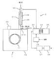
- FIG. 2 is a schematic diagram showing a configuration example of an analyzer equipped with a reactor 21 according to an embodiment of the present invention. Since the configuration other than the reaction device 21 in the analyzer is the same as that in FIG. 1 described above, detailed description of the configuration other than the reaction device 21 is omitted.
- This embodiment is different from the configuration of FIG. 1 only in that an inert gas such as nitrogen or a rare gas is supplied into the reaction device 21.
- the rare gas is, for example, helium gas or argon gas.
- the inert gas is supplied into the reaction device 21 on the upstream side of the reaction tube 28 in the same manner as the oxidant, and is supplied into the reaction tube 28 together with the oxidant.
- FIG. 3 is a cross-sectional view showing a configuration example of the reaction device 21.
- the reaction apparatus 21 is used for SCD2, which is an example of a chemiluminescence detector. That is, the reaction device 21 is used in a chemiluminescence detector that detects chemiluminescence generated in the reaction cell 22 by the detection unit 25, and chemiluminescence detection that oxidizes and reduces the sample gas before being introduced into the reaction cell 22. It is a reactor for vessels.
- the reaction apparatus 21 includes a main body 31, an inflow pipe 32, an outflow pipe 33, and the like in addition to the reaction pipe 28, the heating mechanism 29, and the joint portion 30 described with reference to FIG.
- the reaction tube 28, the heating mechanism 29, and the joint unit 30 are attached to the main body 31.
- the main body 31 is an elongated hollow member extending in a straight line, and a reaction tube 28 is attached so that the inside extends on the same axis, and a heating comprising a cylindrical heater is provided so as to surround the outer periphery of the reaction tube 28.
- a mechanism 29 is attached.
- the reaction tube 28 has a length of 30 to 40 cm and an inner diameter of 2 to 4 mm, for example.
- the joint portion 30 is attached at one end portion (upper end portion) of the main body 31 so as to communicate with the end portion of the reaction tube 28.
- An introduction path 311 communicating with the column 11 is formed at the other end (lower end) of the main body 31, that is, the end opposite to the joint 30 side.
- the sample gas that has passed through the column 11 is introduced into the main body 31 from the introduction path 311 and flows into the reaction tube 28.
- an oxidant inflow path 312 into which an oxidant flows and an inert gas supply path 313 for supplying an inert gas into the main body 31 are formed at the lower end of the main body 31. Yes.
- the sample gas introduced into the main body 31 from the introduction path 311 is mixed with the oxidant flowing in from the oxidant inflow path 312 and the inert gas flowing in from the inert gas supply path 313. It flows into the reaction tube 28.
- the heating mechanism 29 heats the sample gas mixed with the oxidant and the inert gas flowing into the reaction tube 28 by heating the reaction tube 28 from the outside.
- the temperature of the heating mechanism 29 is, for example, 800 to 1000 ° C.
- a reducing agent flows into the reaction tube 28 from the inflow tube 32. Sample gas, oxidant, reducing agent and inert gas are supplied into the reaction tube 28, and the sample gas is oxidized inside. And reduced.
- the reaction tube 28 and the inflow tube 32 are each formed of an alumina sintered body. In order to improve the denseness of the sintered body, an additive made of an alkali metal or an alkaline earth metal is added between the alumina crystals in the sintered body.
- the reaction tube 28 and the inflow tube 32 are both elongated tubes extending in a straight line, but the inflow tube 32 has a smaller diameter than the reaction tube 28.
- a part of the inflow pipe 32 is inserted into the reaction tube 28 so that one end (lower end) reaches partway in the reaction tube 28.
- the inflow pipe 32 constitutes an inner tube and the reaction tube 28 constitutes an outer tube, and a space is formed between the outer peripheral surface of the inflow pipe 32 and the inner peripheral surface of the reaction tube 28.
- the joint portion 30 is a cylindrical member formed of a metal such as stainless steel, for example, and has a gas flow path formed therein. Specifically, a sample inflow path 301, a reducing agent inflow path 302, an outflow path 303, and the like are formed in the joint portion 30.
- the sample inflow path 301 extends from one end portion (lower end portion) of the joint portion 30 along the axis.
- the reducing agent inflow path 302 extends along the axis from the other end (upper end) of the joint part 30, and communicates with the sample inflow path 301 at the center of the joint part 30.
- the outflow channel 303 extends from the outer peripheral surface of the joint unit 30 in a direction orthogonal to the axis, and communicates with the sample inflow channel 301 and the reducing agent inflow channel 302 at the center of the joint unit 30.
- a T-shaped flow path including the sample inflow path 301, the reducing agent inflow path 302, and the outflow path 303 is formed in the joint portion 30.
- the sample inflow path 301, the reducing agent inflow path 302, and the outflow path 303 are configured to communicate with each other in the joint portion 30, for example, the sample inflow path 301 and the reducing agent inflow path 302 extend in an orthogonal direction.
- a flow path may be sufficient, and the flow path of other shapes, such as not only T shape but Y shape, may be formed in the joint part 30.
- an end (upper end) of the reaction tube 28 opposite to the column 11 side is inserted. Thereby, the sample gas flows into the sample inflow path 301 from the heating mechanism 29 side.
- An introduction member 34 is attached to the inlet of the reducing agent inflow path 302, and the reducing agent flows into the reducing agent inflow path 302 through the introduction member 34.
- One end (upper end) of the above-described inflow pipe 32 is inserted into the reducing agent inflow path 302, but the inflow pipe 32 is longer than the joint portion 30, so the other end (lower end) of the inflow pipe 32. Is inserted into the reaction tube 28 outside the joint portion 30 through the sample inflow path 301. Specifically, the other end (lower end) of the inflow pipe 32 is inserted into a portion of the reaction tube 28 surrounded by the heating mechanism 29.
- the reducing agent flowing into the reducing agent inflow path 302 is supplied into the reaction tube 28 through the inflow tube 32 and mixed with the sample gas, the oxidizing agent, and the inert gas in the reaction tube 28.
- the sample gas is oxidized and reduced by reacting in a state where the sample gas, the oxidizing agent, the reducing agent, and the inert gas are mixed, and the sample gas after being oxidized and reduced is supplied to the inflow tube.
- 32 flows into the sample inflow path 301 through a space between the outer peripheral surface of 32 and the inner peripheral surface of the reaction tube 28.
- the sample inflow path 301 extends to the outflow path 303 along the outer periphery of the inflow pipe 32.
- the other end of the outflow pipe 33 whose one end communicates with the reaction cell 22 is attached to the outflow path 303.
- the oxidized and reduced sample gas flowing into the sample inflow path 301 flows out from the outflow pipe 33 through the outflow path 303.
- Graphite seal members 35 and 36 are respectively provided at the inlet of the sample inflow passage 301 and the inlet of the reducing agent inflow passage 302 in the joint portion 30. These seal members 35 and 36 are so-called ferrules, and are constituted by annular members having a frustoconical tapered surface on the outer peripheral surface.
- the seal member 35 closes the gap between the inlet of the sample inflow path 301 and one end (lower end) of the reaction tube 28.
- the seal member 36 closes a gap between the inlet of the reducing agent inflow path 302 and one end (upper end) of the inflow pipe 32.
- a seal member 37 is provided at the other end (lower end) of the reaction tube 28 in the same manner as one end (upper end). The seal member 37 closes a gap between the main body 31 and the other end (lower end) of the reaction tube 28.
- the oxidizing gas, the reducing agent, and the inert gas are supplied into the reaction tube 28 formed of the sintered body of alumina, and the sample gas is oxidized and reduced inside. it can. Therefore, for example, even when the additive present between the alumina crystals in the sintered body reacts with the reducing agent, the emission generated at that time can be efficiently discharged by the inert gas. As a result, contamination that hinders activation of the alumina sintered body can be reduced, so that the aging time can be shortened.
- the inert gas can be supplied into the reaction tube 28 by using a flow path into which the oxidant flows into the reaction tube 28. Therefore, the inert gas can be efficiently supplied into the reaction tube 28 with a simple configuration.
- the inert gas is not limited to a configuration in which the inert gas is supplied into the main body 31 from a flow path different from that of the oxidant and is mixed with the oxidant in front of the reaction tube 28. Above, it may be supplied into the body 31.
- nitrogen having low reactivity is supplied as an inert gas into the reaction tube 28, so that contamination that hinders activation of the alumina sintered body can be effectively reduced. Can do. Such an effect can be similarly achieved when a rare gas is used as the inert gas.
- Example FIG. 4 is a diagram showing the relationship between the flow rate of inert gas, the sensitivity of SCD2, and the selection ratio.
- the temperature of the reaction tube 28 is heated to 800 ° C.
- oxygen as an oxidant is introduced at 10 mL / min
- hydrogen as a reducing agent is introduced at 80 mL / min
- nitrogen is introduced as an inert gas. The results are shown.
- the flow rate of the inert gas is gradually increased, then gradually decreased, and then increased again, so that the sensitivity of sulfur in SCD2 and the selectivity ratio of sulfur to hydrocarbon (sulfur sensitivity / hydrocarbon) The change over time of each was observed. As a result, it was confirmed that the sensitivity and selectivity of sulfur increased as the flow rate of the inert gas increased.
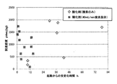
- FIG. 5 is a diagram showing the relationship between the time until the sensitivity of SCD2 is stabilized and the arrival sensitivity.
- FIG. 4 there are a case where only oxygen as an oxidant is caused to flow into the reaction tube 28 and a case where oxidant (oxygen) mixed with nitrogen as an inert gas is caused to flow into the reaction tube 28. It is shown.
- the flow rate of the inert gas (nitrogen) mixed with the oxidant is 40 mL / min.
- the aging time can be set to a short time of 15 hours or less.
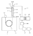
- FIG. 6 is a schematic diagram of an analysis apparatus showing a modification of the reaction apparatus 21. Since the configuration other than the reaction device 21 in the analyzer is the same as that in FIG. 2 described above, detailed description of the configuration other than the reaction device 21 is omitted.
- an inert gas composed of nitrogen or a rare gas is supplied into the reaction apparatus 21 in the same manner as in FIG. 1, but the inert gas is not an oxidant but a reducing agent together with the reaction tube 28. 1 is different from the case of FIG. Specifically, an inert gas supply path 314 for supplying an inert gas is formed in the joint part 30, and the inert gas flowing from the inert gas supply path 314 is added to the reducing agent flowing into the joint part 30. After being mixed, it flows into the reaction tube 28. Except this point, the other structure in the reaction apparatus 21 is the same as that of FIG.
- the inert gas can be supplied into the reaction tube 28 using the flow path into which the reducing agent flows into the reaction tube 28. Therefore, the inert gas can be efficiently supplied into the reaction tube 28 with a simple configuration.
- the inert gas is not limited to a configuration in which the inert gas is supplied into the joint portion 30 from a flow path different from that of the reducing agent and is mixed with the reducing agent before the reaction tube 28.
- the inert gas is mixed with the reducing agent in advance. In addition, it may be supplied into the joint portion 30.
Landscapes
- Chemical & Material Sciences (AREA)
- Physics & Mathematics (AREA)
- Health & Medical Sciences (AREA)
- General Health & Medical Sciences (AREA)
- Analytical Chemistry (AREA)
- Immunology (AREA)
- Biochemistry (AREA)
- General Physics & Mathematics (AREA)
- Life Sciences & Earth Sciences (AREA)
- Pathology (AREA)
- Chemical Kinetics & Catalysis (AREA)
- Engineering & Computer Science (AREA)
- Plasma & Fusion (AREA)
- Hematology (AREA)
- Clinical Laboratory Science (AREA)
- Spectroscopy & Molecular Physics (AREA)
- Investigating Or Analysing Materials By The Use Of Chemical Reactions (AREA)
- Investigating Or Analyzing Non-Biological Materials By The Use Of Chemical Means (AREA)
Abstract
反応装置21は、反応管28と、不活性ガス供給路313とを備える。反応管28は、アルミナの焼結体により形成され、内部で試料ガスを酸化及び還元させる。不活性ガス供給路313は、反応管28内に不活性ガスを供給する。これにより、アルミナの焼結体を活性化させる際の妨げとなる汚染を軽減することができるため、エージングの時間を短縮することができる。
Description
本発明は、反応セル内で生じた化学発光を検出部で検出する化学発光検出器に用いられ、前記反応セルに導入される前の試料ガスを酸化及び還元させる化学発光検出器用反応装置及びこれを備えた化学発光検出器、並びに、化学発光検出方法に関するものである。
クロマトグラフィー分離と組み合わせて試料中のヘテロ原子である硫黄の含有量を定量するために、高い化合物選択性を実現する化学発光を応用した検出器が利用されている。例えば、硫黄化合物の化学発光を利用した硫黄検出方法は、従来から複数存在している。古くは炎光光度計(FPD:Flame Photometric Detector)、近年では、さらに高性能化した硫黄化学発光検出器(SCD:Sulfur Chemiluminescence Detector)が知られている(例えば、下記特許文献1及び2、非特許文献1参照)。
FPDを用いた分析では、水素炎中で生成される二原子の硫黄分子の励起種S2
*の化学発光が、光増倍管などからなる検出部で検出される。そのため、二次反応を利用している欠点として、検量線は非線形になる。一方、SCDを用いた分析では、例えば含硫黄化合物の酸化及び還元により生じる硫黄化合物と、オゾンとの反応により、二酸化硫黄の励起種SO2
*の化学発光が生じ、その化学発光が光増倍管などからなる検出部で検出される。
以下に、SCDを用いた分析の反応例を示す。
<反応装置における反応>
含硫黄化合物+O2(酸化剤)→SO2+CO2+H2O+・・・
SO2+H2(還元剤)→SO+H2O
<反応セルにおける反応>
SO+O3→SO2 *+O2
SO2 *→SO2+hν
クロマトグラフィー分離後の試料ガスは、反応装置において酸化及び還元された後、反応セルへと導かれ、反応セル内で生じたSO2 *の化学発光がSCDにより検出される。SCDは、FPDよりも感度と直線応答に優れているため、炭素と硫黄の選択性が改善される。
<反応装置における反応>
含硫黄化合物+O2(酸化剤)→SO2+CO2+H2O+・・・
SO2+H2(還元剤)→SO+H2O
<反応セルにおける反応>
SO+O3→SO2 *+O2
SO2 *→SO2+hν
クロマトグラフィー分離後の試料ガスは、反応装置において酸化及び還元された後、反応セルへと導かれ、反応セル内で生じたSO2 *の化学発光がSCDにより検出される。SCDは、FPDよりも感度と直線応答に優れているため、炭素と硫黄の選択性が改善される。
図1は、SCD2を用いた分析装置の構成例を示す概略図である。この分析装置には、ガスクロマトグラフ1と、当該ガスクロマトグラフ1により分離された試料成分を検出するSCD2とが備えられている。
ガスクロマトグラフ1は、カラム11、カラムオーブン12及び試料導入部13などを備えている。カラム11は、例えばキャピラリカラムからなり、分析中はカラムオーブン12内で加熱される。試料導入部13は、内部に試料気化室を備えており、この試料気化室内で気化された試料(試料ガス)がキャリアガスとともにカラム11内に導入される。試料ガス中の試料成分(化合物)は、カラム11を通過する過程で分離され、SCD2へと導かれる。
SCD2は、反応装置21、反応セル22、オゾナイザー23、フィルタ24、検出部25、ポンプ26及びスクラバ27などを備えている。反応装置21は、カラム11から導入される試料ガスを酸化及び還元させる。例えば、試料ガス中の試料成分の一例である含硫黄化合物は、酸化剤としてのO2を用いて反応装置21内で酸化されることにより、SO2が生成される。そして、生成されたSO2は、還元剤としてのH2を用いて反応装置21内で還元されることにより、SOが生成される。このようにして生成されるSOは、オゾンとの反応により化学発光が可能な硫黄化合物である。ただし、酸化剤はO2に限られるものではなく、還元剤はH2に限られるものではない。
反応装置21には、反応管28、加熱機構29及びジョイント部30などが備えられている。反応管28は、例えばセラミックス製のチューブであり、カラム11を通過した試料ガスは、酸化剤と混合された上で反応管28内に流入する。反応管28は、その周囲に設けられた加熱機構29により加熱される。ジョイント部30は、例えばT字状の流路が内部に形成されたTジョイントにより構成されている。ジョイント部30は、還元剤を反応管28内に流入させるとともに、反応管28を通過した試料ガスを反応装置21から流出させる。すなわち、カラム11からの試料ガスは、反応管28内において酸化及び還元された後、ジョイント部30から反応セル22へと導かれる。
反応セル22には、オゾナイザー23からオゾンが供給される。オゾナイザー23では、酸素から無声放電によりオゾンが生成される。反応装置21から反応セル22内に導かれた試料ガスは、オゾナイザー23から供給されるオゾンと反応セル22内で混合される。そして、反応セル22内での反応により、励起された二酸化硫黄が生じ、化学発光が観察される。反応セル22内で生じた化学発光は、フィルタ24を介して、例えば光増倍管からなる検出部25により検出される。これにより、二酸化硫黄の発光量に応じた検出信号が検出部25から出力され、その検出信号に基づいて試料ガス中の硫黄含有量を定量することができる。
反応装置21から反応セル22への試料ガスの導入は、反応セル22に接続されたポンプ26の作用により行われる。すなわち、ポンプ26の吸引動作により、反応装置21から反応セル22内に試料ガスが導かれ、反応セル22内においてオゾンと反応した後の試料ガスは、ポンプ26を介して排出される。反応セル22とポンプ26との間には、スクラバ27が介装されており、反応セル22からの試料ガスは、スクラバ27によりオゾンが除去された上で排出される。
Journal of Catalysis vol. 24 (1972) pp. 115-120
反応装置21の反応管28は、例えば高純度のアルミナの焼結体により形成されている。アルミナの焼結体を活性化させるためには、初回使用時に、いわゆるエージングを行う必要がある。すなわち、焼結体におけるアルミナの結晶間には、焼結体の緻密性を向上するためにアルカリ金属又はアルカリ土類金属などからなる添加剤が添加されているが、初回使用時には、その添加剤が還元剤と反応して検出器の出力が大きくなるため、感度が安定するまで待つこと(エージング)が必要となる。
反応管28は消耗品であり、経時劣化又は汚染によって活性が変化した場合には、試料成分の感度低下として症状が現れるため、反応管28の交換が必要となる。この場合、反応管28を交換すれば、感度を回復させることが可能であるが、必要とされるエージングの時間に大きなばらつきがある。そのため、エージングの時間は比較的長い時間に設定する必要があり、分析を開始するまでの待ち時間が長くなるという問題がある。
本発明は、上記実情に鑑みてなされたものであり、エージングの時間を短縮することができる化学発光検出器用反応装置及びこれを備えた化学発光検出器、並びに、化学発光検出方法を提供することを目的とする。
(1)本発明に係る化学発光検出器用反応装置は、反応セル内で生じた化学発光を検出部で検出する化学発光検出器に用いられ、前記反応セルに導入される前の試料ガスを酸化及び還元させる化学発光検出器用反応装置であって、反応管と、不活性ガス供給路とを備える。前記反応管は、アルミナの焼結体により形成され、内部で試料ガスを酸化及び還元させる。前記不活性ガス供給路は、前記反応管内に不活性ガスを供給する。
このような構成によれば、アルミナの焼結体により形成された反応管内に、酸化剤、還元剤及び不活性ガスを供給して、内部で試料ガスを酸化及び還元させることができる。したがって、例えば焼結体におけるアルミナの結晶間に存在する添加剤が還元剤と反応した場合などであっても、その際に生じる放出物を不活性ガスにより効率よく排出させることができる。これにより、アルミナの焼結体を活性化させる際の妨げとなる汚染を軽減することができるため、エージングの時間を短縮することができる。
(2)前記不活性ガス供給路からの不活性ガスが、酸化剤とともに前記反応管内に供給されてもよい。
このような構成によれば、反応管内に酸化剤が流入する流路を利用して、不活性ガスを反応管内に供給することができる。したがって、簡単な構成で反応管内に効率よく不活性ガスを供給することができる。
(3)前記不活性ガス供給路からの不活性ガスが、還元剤とともに前記反応管内に供給されてもよい。
このような構成によれば、反応管内に還元剤が流入する流路を利用して、不活性ガスを反応管内に供給することができる。したがって、簡単な構成で反応管内に効率よく不活性ガスを供給することができる。
(4)前記不活性ガスが、窒素又は希ガスであってもよい。
このような構成によれば、反応性が低い窒素又は希ガスが、不活性ガスとして反応管内に供給されるため、アルミナの焼結体を活性化させる際の妨げとなる汚染を効果的に軽減することができる。
(5)本発明に係る化学発光検出器は、前記化学発光検出器用反応装置と、前記反応管内で酸化及び還元された試料ガスが流入する反応セルと、前記反応セル内で生じた化学発光を検出する検出部とを備える。
(6)本発明に係る化学発光検出方法は、試料ガスを酸化及び還元させて反応セルに導入し、前記反応セル内で生じた化学発光を検出部で検出する化学発光検出方法であって、アルミナの焼結体により形成された反応管内に、酸化剤、還元剤及び不活性ガスを供給して、内部で試料ガスを酸化及び還元させることを特徴とする化学発光検出方法。
本発明によれば、反応管内に供給される不活性ガスにより、アルミナの焼結体を活性化させる際の妨げとなる汚染を軽減することができるため、エージングの時間を短縮することができる。
1.反応装置の構成
図2は、本発明の一実施形態に係る反応装置21を備えた分析装置の構成例を示す概略図である。分析装置における反応装置21以外の構成は、上述した図1と同様の構成であるため、反応装置21以外の構成については詳細な説明を省略する。
図2は、本発明の一実施形態に係る反応装置21を備えた分析装置の構成例を示す概略図である。分析装置における反応装置21以外の構成は、上述した図1と同様の構成であるため、反応装置21以外の構成については詳細な説明を省略する。
本実施形態では、反応装置21内に窒素又は希ガスなどからなる不活性ガスが供給される点のみが、図1の構成とは異なっている。希ガスは、例えばヘリウムガス又はアルゴンガスなどである。不活性ガスは、酸化剤と同じく反応管28の上流側で反応装置21内に供給され、酸化剤とともに反応管28内に供給される。
図3は、反応装置21の構成例を示す断面図である。反応装置21は、化学発光検出器の一例であるSCD2に用いられる。すなわち、反応装置21は、反応セル22内で生じた化学発光を検出部25で検出する化学発光検出器に用いられ、反応セル22に導入される前の試料ガスを酸化及び還元させる化学発光検出器用反応装置である。
反応装置21には、図1を用いて説明した反応管28、加熱機構29及びジョイント部30の他に、本体31、流入管32及び流出管33などが備えられている。反応管28、加熱機構29及びジョイント部30は、本体31に取り付けられている。
本体31は、一直線上に延びる細長い中空状の部材であり、その内部を同一軸線上に延びるように反応管28が取り付けられるとともに、反応管28の外周を取り囲むように円筒状のヒータからなる加熱機構29が取り付けられる。反応管28は、例えば長さが30~40cm、内径が2~4mmである。また、ジョイント部30は、本体31の一端部(上端部)において、反応管28の端部に連通するように取り付けられる。
本体31の他端部(下端部)、すなわちジョイント部30側とは反対側の端部には、カラム11に連通する導入路311が形成されている。カラム11を通過した試料ガスは、導入路311から本体31内に導入され、反応管28内に流入する。また、本体31の下端部には、導入路311の他に、酸化剤が流入する酸化剤流入路312と、本体31内に不活性ガスを供給する不活性ガス供給路313とが形成されている。これにより、導入路311から本体31内に導入される試料ガスは、酸化剤流入路312から流入する酸化剤、及び、不活性ガス供給路313から流入する不活性ガスが混合された上で、反応管28内に流入するようになっている。
加熱機構29は、反応管28を外側から加熱することにより、反応管28内に流入する酸化剤及び不活性ガスが混合された試料ガスを加熱する。加熱機構29の温度は、例えば800~1000℃である。反応管28内には、流入管32から還元剤が流入するようになっており、反応管28内に試料ガス、酸化剤、還元剤及び不活性ガスが供給されて、内部で試料ガスが酸化及び還元される。
反応管28及び流入管32は、それぞれアルミナの焼結体により形成されている。焼結体におけるアルミナの結晶間には、焼結体の緻密性を向上するためにアルカリ金属又はアルカリ土類金属などからなる添加剤が添加されている。反応管28及び流入管32は、いずれも一直線上に延びる細長いチューブであるが、流入管32の方が反応管28よりも小径である。流入管32は、一方の端部(下端部)が反応管28内の途中まで到達するように、その一部が反応管28内に挿入されている。これにより、流入管32がインナーチューブ、反応管28がアウタチューブを構成しており、流入管32の外周面と反応管28の内周面との間には空間が形成されている。
ジョイント部30は、例えばステンレス鋼などの金属により形成された円筒状の部材であり、内部にガスの流路が形成されている。具体的には、試料流入路301、還元剤流入路302及び流出路303などがジョイント部30内に形成されている。試料流入路301は、ジョイント部30の一端部(下端部)から軸線に沿って延びている。還元剤流入路302は、ジョイント部30の他端部(上端部)から軸線に沿って延びており、ジョイント部30の中央部において試料流入路301に連通している。流出路303は、ジョイント部30の外周面から軸線に対して直交方向に延びており、ジョイント部30の中央部において試料流入路301及び還元剤流入路302に連通している。
このように、ジョイント部30内には、試料流入路301、還元剤流入路302及び流出路303により構成されるT字状の流路が形成されている。ただし、試料流入路301、還元剤流入路302及び流出路303がジョイント部30内で連通するような構成であれば、例えば試料流入路301と還元剤流入路302が互いに直交方向に延びるような流路であってもよいし、T字状に限らず、Y字状などの他の形状の流路がジョイント部30内に形成されていてもよい。
試料導入路301には、反応管28におけるカラム11側とは反対側の端部(上端部)が挿入されている。これにより、試料流入路301には、加熱機構29側から試料ガスが流入するようになっている。還元剤流入路302には、その入口に導入部材34が取り付けられており、当該導入部材34を介して還元剤流入路302内に還元剤が流入する。還元剤流入路302には、上述の流入管32の一端部(上端部)が挿入されているが、流入管32はジョイント部30よりも長いため、流入管32の他端部(下端部)は、試料流入路301を通って、ジョイント部30の外側において反応管28内に挿入されている。具体的には、流入管32の他端部(下端部)は、反応管28における加熱機構29に取り囲まれた部分にまで挿入されている。
したがって、還元剤流入路302に流入する還元剤は、流入管32を通って反応管28内に供給され、反応管28内において試料ガス、酸化剤及び不活性ガスと混合される。反応管28内では、試料ガス、酸化剤、還元剤及び不活性ガスが混合された状態で反応することにより、試料ガスが酸化及び還元され、酸化及び還元された後の試料ガスが、流入管32の外周面と反応管28の内周面との間の空間を通って試料流入路301に流入する。
試料流入路301は、流入管32の外周に沿って流出路303まで延びている。流出路303には、一端部が反応セル22に連通する流出管33の他端部が取り付けられている。これにより、試料流入路301内に流入する酸化及び還元された後の試料ガスは、流出路303を通って流出管33から流出する。
ジョイント部30における試料流入路301の入口、及び、還元剤流入路302の入口には、それぞれグラファイト製のシール部材35,36が設けられている。これらのシール部材35,36は、いわゆるフェルールであり、外周面に円錐台状のテーパ面を有する環状の部材により構成されている。
シール部材35は、試料流入路301の入口と反応管28の一端部(下端部)との隙間を閉塞している。一方、シール部材36は、還元剤流入路302の入口と流入管32の一端部(上端部)との隙間を閉塞している。これらのシール部材36により、ジョイント部30内の気密性が向上し、ジョイント部30内のガスが外部に漏れたり、外部の空気がジョイント部30内に流入したりすることを抑制できる。反応管28の他端部(下端部)には、一端部(上端部)と同じくシール部材37が設けられている。このシール部材37は、本体31と反応管28の他端部(下端部)との隙間を閉塞している。
以上のように、本実施形態では、アルミナの焼結体により形成された反応管28内に、酸化剤、還元剤及び不活性ガスを供給して、内部で試料ガスを酸化及び還元させることができる。したがって、例えば焼結体におけるアルミナの結晶間に存在する添加剤が還元剤と反応した場合などであっても、その際に生じる放出物を不活性ガスにより効率よく排出させることができる。これにより、アルミナの焼結体を活性化させる際の妨げとなる汚染を軽減することができるため、エージングの時間を短縮することができる。
特に、本実施形態では、反応管28内に酸化剤が流入する流路を利用して、不活性ガスを反応管28内に供給することができる。したがって、簡単な構成で反応管28内に効率よく不活性ガスを供給することができる。ただし、不活性ガスは、酸化剤とは異なる流路から本体31内に供給されて、反応管28の手前で酸化剤と混合されるような構成に限らず、例えば予め酸化剤と混合された上で、本体31内に供給されてもよい。
また、本実施形態では、反応性が低い窒素が、不活性ガスとして反応管28内に供給されるため、アルミナの焼結体を活性化させる際の妨げとなる汚染を効果的に軽減することができる。このような効果は、不活性ガスとして希ガスを用いた場合にも同様に奏することができる。
2.実施例
図4は、不活性ガスの流量、SCD2の感度及び選択比の関係を示す図である。図4には、反応管28の温度を800℃に加熱し、酸化剤としての酸素を10mL/min、還元剤としての水素を80mL/minで導入するとともに、不活性ガスとして窒素を導入した場合の結果が示されている。
図4は、不活性ガスの流量、SCD2の感度及び選択比の関係を示す図である。図4には、反応管28の温度を800℃に加熱し、酸化剤としての酸素を10mL/min、還元剤としての水素を80mL/minで導入するとともに、不活性ガスとして窒素を導入した場合の結果が示されている。
この例では、不活性ガスの流量を徐々に増加させた後、徐々に減少させ、再び上昇させることにより、SCD2における硫黄の感度、及び、硫黄と炭化水素の選択比(硫黄の感度/炭化水素の感度)について、それぞれの経時的変化を観察した。その結果、不活性ガスの流量の増加に伴って、硫黄の感度及び選択比が上昇することが確認できた。
不活性ガスの流量を徐々に減少させると、タイムラグはあるものの、硫黄の感度及び選択比が降下することが確認できた。その後、不活性ガスの流量を再度上昇させたときには、硫黄の感度及び選択比が再度上昇することが確認できた。
図5は、SCD2の感度が安定するまでの時間と到達感度の関係を示す図である。図4には、酸化剤としての酸素のみを反応管28内に流入させた場合と、不活性ガスとしての窒素が混合された酸化剤(酸素)を反応管28内に流入させた場合とが示されている。酸化剤に混合させる不活性ガス(窒素)の流量は、40mL/minである。
この結果から、酸化剤のみを反応管28内に流入させたときには、分析装置を起動してから約80時間経過するまで、SCD2の感度が安定しない場合があることが確認できた。このような場合を想定して、酸化剤のみを反応管28内に流入させるような構成の場合には、SCD2の感度が安定するまでの時間(エージング時間)として、80時間を超える長い時間を設定する必要がある。
これに対して、不活性ガスが混合された酸化剤を反応管28内に流入させたときには、最終的に到達するSCD2の感度にはばらつきがあるものの、いずれの実験結果においても15時間以内にSCD2の感度が安定した。したがって、不活性ガスが混合された酸化剤を反応管28内に流入させるような構成の場合には、エージング時間を15時間以下の短い時間に設定することができる。
3.変形例
図6は、反応装置21の変形例を示す分析装置の概略図である。分析装置における反応装置21以外の構成は、上述した図2と同様の構成であるため、反応装置21以外の構成については詳細な説明を省略する。
図6は、反応装置21の変形例を示す分析装置の概略図である。分析装置における反応装置21以外の構成は、上述した図2と同様の構成であるため、反応装置21以外の構成については詳細な説明を省略する。
この例では、反応装置21内に窒素又は希ガスなどからなる不活性ガスが供給される点は図1の場合と同様であるが、酸化剤ではなく、還元剤とともに不活性ガスが反応管28内に供給されるようになっている点が図1の場合と異なっている。具体的には、不活性ガスを供給する不活性ガス供給路314がジョイント部30に形成されており、ジョイント部30に流入する還元剤に、不活性ガス供給路314から流入する不活性ガスが混合された上で、反応管28内に流入するようになっている。この点を除けば、反応装置21における他の構成は図3と同様である。
このような構成によれば、反応管28内に還元剤が流入する流路を利用して、不活性ガスを反応管28内に供給することができる。したがって、簡単な構成で反応管28内に効率よく不活性ガスを供給することができる。ただし、不活性ガスは、還元剤とは異なる流路からジョイント部30内に供給されて、反応管28の手前で還元剤と混合されるような構成に限らず、例えば予め還元剤と混合された上で、ジョイント部30内に供給されてもよい。
1 ガスクロマトグラフ
2 SCD
11 カラム
12 カラムオーブン
13 試料導入部
21 反応装置
22 反応セル
23 オゾナイザー
24 フィルタ
25 検出部
26 ポンプ
27 スクラバ
28 反応管
29 加熱機構
30 ジョイント部
31 本体
32 流入管
33 流出管
34 導入部材
35~37 シール部材
301 試料流入路
302 還元剤流入路
303 流出路
311 導入路
312 酸化剤流入路
313 不活性ガス供給路
314 不活性ガス供給路
2 SCD
11 カラム
12 カラムオーブン
13 試料導入部
21 反応装置
22 反応セル
23 オゾナイザー
24 フィルタ
25 検出部
26 ポンプ
27 スクラバ
28 反応管
29 加熱機構
30 ジョイント部
31 本体
32 流入管
33 流出管
34 導入部材
35~37 シール部材
301 試料流入路
302 還元剤流入路
303 流出路
311 導入路
312 酸化剤流入路
313 不活性ガス供給路
314 不活性ガス供給路
Claims (6)
- 反応セル内で生じた化学発光を検出部で検出する化学発光検出器に用いられ、前記反応セルに導入される前の試料ガスを酸化及び還元させる化学発光検出器用反応装置であって、
アルミナの焼結体により形成され、内部で試料ガスを酸化及び還元させる反応管と、
前記反応管内に不活性ガスを供給する不活性ガス供給路とを備えることを特徴とする化学発光検出器用反応装置。 - 前記不活性ガス供給路からの不活性ガスが、酸化剤とともに前記反応管内に供給されることを特徴とする請求項1に記載の化学発光検出器用反応装置。
- 前記不活性ガス供給路からの不活性ガスが、還元剤とともに前記反応管内に供給されることを特徴とする請求項1に記載の化学発光検出器用反応装置。
- 前記不活性ガスが、窒素又は希ガスであることを特徴とする請求項1に記載の化学発光検出器用反応装置。
- 請求項1に記載の化学発光検出器用反応装置と、
前記反応管内で酸化及び還元された試料ガスが流入する反応セルと、
前記反応セル内で生じた化学発光を検出する検出部とを備えることを特徴とする化学発光検出器。 - 試料ガスを酸化及び還元させて反応セルに導入し、前記反応セル内で生じた化学発光を検出部で検出する化学発光検出方法であって、
アルミナの焼結体により形成された反応管内に、酸化剤、還元剤及び不活性ガスを供給して、内部で試料ガスを酸化及び還元させることを特徴とする化学発光検出方法。
Priority Applications (3)
| Application Number | Priority Date | Filing Date | Title |
|---|---|---|---|
| US16/490,685 US20200003695A1 (en) | 2017-03-15 | 2018-03-07 | Reaction device for chemiluminescence detector, chemiluminescence detector equipped with same, and chemiluminescence detection method |
| CN201880008321.2A CN110214269A (zh) | 2017-03-15 | 2018-03-07 | 化学发光检测器用反应装置以及具备该反应装置的化学发光检测器、与化学发光检测方法 |
| JP2019505919A JP6729789B2 (ja) | 2017-03-15 | 2018-03-07 | 化学発光検出器用反応装置及びこれを備えた化学発光検出器、並びに、化学発光検出方法 |
Applications Claiming Priority (2)
| Application Number | Priority Date | Filing Date | Title |
|---|---|---|---|
| JP2017049513 | 2017-03-15 | ||
| JP2017-049513 | 2017-03-15 |
Publications (1)
| Publication Number | Publication Date |
|---|---|
| WO2018168599A1 true WO2018168599A1 (ja) | 2018-09-20 |
Family
ID=63522238
Family Applications (1)
| Application Number | Title | Priority Date | Filing Date |
|---|---|---|---|
| PCT/JP2018/008727 Ceased WO2018168599A1 (ja) | 2017-03-15 | 2018-03-07 | 化学発光検出器用反応装置及びこれを備えた化学発光検出器、並びに、化学発光検出方法 |
Country Status (4)
| Country | Link |
|---|---|
| US (1) | US20200003695A1 (ja) |
| JP (1) | JP6729789B2 (ja) |
| CN (1) | CN110214269A (ja) |
| WO (1) | WO2018168599A1 (ja) |
Cited By (4)
| Publication number | Priority date | Publication date | Assignee | Title |
|---|---|---|---|---|
| WO2020121426A1 (ja) * | 2018-12-12 | 2020-06-18 | 株式会社島津製作所 | 化学発光硫黄検出器 |
| WO2020129216A1 (ja) * | 2018-12-20 | 2020-06-25 | 株式会社島津製作所 | 化学発光硫黄検出器 |
| WO2020157969A1 (ja) * | 2019-02-01 | 2020-08-06 | 株式会社島津製作所 | 化学発光硫黄検出器 |
| WO2020161833A1 (ja) * | 2019-02-06 | 2020-08-13 | 株式会社島津製作所 | 化学発光硫黄検出器 |
Families Citing this family (4)
| Publication number | Priority date | Publication date | Assignee | Title |
|---|---|---|---|---|
| NL2017426B1 (en) * | 2016-09-06 | 2018-03-13 | Ac Analytical Controls B V | Method for chemiluminescent sulphur detection and a furnace |
| WO2020110408A1 (ja) * | 2018-11-29 | 2020-06-04 | 株式会社島津製作所 | ガスクロマトグラフシステム |
| JP7334507B2 (ja) * | 2019-07-03 | 2023-08-29 | 東京エレクトロン株式会社 | シール構造、真空処理装置及びシール方法 |
| CN118258725A (zh) * | 2024-05-30 | 2024-06-28 | 福建省特种设备检验研究院 | 一种量化金属和聚合物气相氢扩散的测试装置及方法 |
Citations (5)
| Publication number | Priority date | Publication date | Assignee | Title |
|---|---|---|---|---|
| JPH05504835A (ja) * | 1989-12-01 | 1993-07-22 | シーバーズ インスツルメンツ、インコーポレイテッド | 硫黄含有および非硫黄含有化合物の同時測定方法およびその装置 |
| US5935519A (en) * | 1988-11-25 | 1999-08-10 | Sievers Instruments, Inc. | Apparatus for the detection of sulfur |
| US6130095A (en) * | 1992-01-23 | 2000-10-10 | Sievers Instruments, Inc. | Method for the measurement of sulfur compounds |
| JP2013242158A (ja) * | 2012-05-17 | 2013-12-05 | Shimadzu Corp | 成分分析装置および成分分析方法 |
| JP2015187588A (ja) * | 2014-03-27 | 2015-10-29 | 株式会社島津製作所 | 成分分析装置及び成分分析方法 |
Family Cites Families (7)
| Publication number | Priority date | Publication date | Assignee | Title |
|---|---|---|---|---|
| US5916523A (en) * | 1996-12-04 | 1999-06-29 | Antek Instruments, Inc. | Methods for near simultaneous chemiluminescent sulfur and nitrogen detection |
| JP4109578B2 (ja) * | 2003-06-13 | 2008-07-02 | 株式会社堀場製作所 | 化学発光式ガス分析方法および装置 |
| CN103175825A (zh) * | 2013-02-05 | 2013-06-26 | 中联煤层气国家工程研究中心有限责任公司 | 一种检测煤层气中硫化物含量的方法和装置 |
| CN103616468A (zh) * | 2013-11-27 | 2014-03-05 | 深圳供电局有限公司 | 一种sf6气相色谱检测系统及方法 |
| CN105136917A (zh) * | 2015-07-22 | 2015-12-09 | 华北电力大学 | 一种变压器油中多重硫化物定性与定量分析的方法 |
| CN105911158B (zh) * | 2016-04-08 | 2018-04-17 | 中国测试技术研究院化学研究所 | 一种测定天然气中硫化物总含量的气相色谱仪及检测方法 |
| CN105973810A (zh) * | 2016-06-12 | 2016-09-28 | 珀金埃尔默企业管理(上海)有限公司 | 一种微型液体反应装置及其使用方法 |
-
2018
- 2018-03-07 JP JP2019505919A patent/JP6729789B2/ja active Active
- 2018-03-07 WO PCT/JP2018/008727 patent/WO2018168599A1/ja not_active Ceased
- 2018-03-07 CN CN201880008321.2A patent/CN110214269A/zh active Pending
- 2018-03-07 US US16/490,685 patent/US20200003695A1/en not_active Abandoned
Patent Citations (5)
| Publication number | Priority date | Publication date | Assignee | Title |
|---|---|---|---|---|
| US5935519A (en) * | 1988-11-25 | 1999-08-10 | Sievers Instruments, Inc. | Apparatus for the detection of sulfur |
| JPH05504835A (ja) * | 1989-12-01 | 1993-07-22 | シーバーズ インスツルメンツ、インコーポレイテッド | 硫黄含有および非硫黄含有化合物の同時測定方法およびその装置 |
| US6130095A (en) * | 1992-01-23 | 2000-10-10 | Sievers Instruments, Inc. | Method for the measurement of sulfur compounds |
| JP2013242158A (ja) * | 2012-05-17 | 2013-12-05 | Shimadzu Corp | 成分分析装置および成分分析方法 |
| JP2015187588A (ja) * | 2014-03-27 | 2015-10-29 | 株式会社島津製作所 | 成分分析装置及び成分分析方法 |
Non-Patent Citations (1)
| Title |
|---|
| KHALAFALLA, S. E. ET AL.: "Active Sites for Catalytic Reduction of S02 with CO on Alumina", JOURNAL OF CATALYSIS, vol. 24, 1972, pages 115 - 120, XP055608943 * |
Cited By (22)
| Publication number | Priority date | Publication date | Assignee | Title |
|---|---|---|---|---|
| JPWO2020121426A1 (ja) * | 2018-12-12 | 2021-10-14 | 株式会社島津製作所 | 化学発光硫黄検出器 |
| WO2020121426A1 (ja) * | 2018-12-12 | 2020-06-18 | 株式会社島津製作所 | 化学発光硫黄検出器 |
| JP2023052048A (ja) * | 2018-12-12 | 2023-04-11 | 株式会社島津製作所 | 成分分析システムおよび成分検出装置 |
| US12379321B2 (en) | 2018-12-12 | 2025-08-05 | Shimadzu Corporation | Sulfur chemiluminescence detector |
| US12345651B2 (en) | 2018-12-12 | 2025-07-01 | Shimadzu Corporation | Gas chromatographic component analysis system and component detector including an oxidation-reduction furnace, reaction cell and photodetector |
| CN113167732A (zh) * | 2018-12-12 | 2021-07-23 | 株式会社岛津制作所 | 硫化学发光检测器 |
| WO2020121539A1 (ja) * | 2018-12-12 | 2020-06-18 | 株式会社島津製作所 | 成分分析システムおよび成分検出装置 |
| JP7400935B2 (ja) | 2018-12-12 | 2023-12-19 | 株式会社島津製作所 | 成分分析システムおよび成分検出装置 |
| JP7207422B2 (ja) | 2018-12-12 | 2023-01-18 | 株式会社島津製作所 | 成分分析システムおよび成分検出装置 |
| JPWO2020121539A1 (ja) * | 2018-12-12 | 2021-10-07 | 株式会社島津製作所 | 成分分析システムおよび成分検出装置 |
| CN113167734A (zh) * | 2018-12-12 | 2021-07-23 | 株式会社岛津制作所 | 成分分析系统和成分检测装置 |
| CN113167734B (zh) * | 2018-12-12 | 2025-05-13 | 株式会社岛津制作所 | 成分分析系统和成分检测装置 |
| JP7036228B2 (ja) | 2018-12-12 | 2022-03-15 | 株式会社島津製作所 | 化学発光硫黄検出器 |
| JP7052884B2 (ja) | 2018-12-20 | 2022-04-12 | 株式会社島津製作所 | 化学発光硫黄検出器 |
| JPWO2020129216A1 (ja) * | 2018-12-20 | 2021-10-21 | 株式会社島津製作所 | 化学発光硫黄検出器 |
| WO2020129216A1 (ja) * | 2018-12-20 | 2020-06-25 | 株式会社島津製作所 | 化学発光硫黄検出器 |
| JPWO2020157969A1 (ja) * | 2019-02-01 | 2021-10-28 | 株式会社島津製作所 | 化学発光硫黄検出器 |
| JP7156406B2 (ja) | 2019-02-01 | 2022-10-19 | 株式会社島津製作所 | 化学発光硫黄検出器 |
| WO2020157969A1 (ja) * | 2019-02-01 | 2020-08-06 | 株式会社島津製作所 | 化学発光硫黄検出器 |
| JP7143902B2 (ja) | 2019-02-06 | 2022-09-29 | 株式会社島津製作所 | 化学発光硫黄検出器 |
| JPWO2020161833A1 (ja) * | 2019-02-06 | 2021-10-28 | 株式会社島津製作所 | 化学発光硫黄検出器 |
| WO2020161833A1 (ja) * | 2019-02-06 | 2020-08-13 | 株式会社島津製作所 | 化学発光硫黄検出器 |
Also Published As
| Publication number | Publication date |
|---|---|
| US20200003695A1 (en) | 2020-01-02 |
| CN110214269A (zh) | 2019-09-06 |
| JP6729789B2 (ja) | 2020-07-22 |
| JPWO2018168599A1 (ja) | 2019-11-07 |
Similar Documents
| Publication | Publication Date | Title |
|---|---|---|
| JP6729789B2 (ja) | 化学発光検出器用反応装置及びこれを備えた化学発光検出器、並びに、化学発光検出方法 | |
| JP2015059876A (ja) | 酸化装置、化学発光検出器及びガスクロマトグラフ | |
| JP3725441B2 (ja) | 気体流れ中の不純物を分析するための方法 | |
| JP7070703B2 (ja) | ガスクロマトグラフシステム | |
| JP6995858B2 (ja) | 化学発光硫黄検出方法及び炉 | |
| JP6089445B2 (ja) | 成分分析装置および成分分析方法 | |
| JP3210660U (ja) | 化学発光検出器用反応装置及びこれを備えた化学発光検出器 | |
| US11415521B2 (en) | Furnace suited for chemiluminescent sulphur detection | |
| JP2000065699A (ja) | 分析用試料燃焼装置及び分析用試料燃焼装置における不活性ガス,酸素含有ガス供給制御方法並びに試料燃焼装置を有する分析システム | |
| US11435329B2 (en) | Reaction tube for elemental analysis | |
| JP2010122160A (ja) | 水銀分析装置およびその方法 | |
| JP5684674B2 (ja) | 分析方法及び分析装置 | |
| JP4753083B2 (ja) | 誘導結合プラズマ質量分析及び発光分析装置 | |
| CN213986332U (zh) | 一种用于元素分析的系统 | |
| US12618778B2 (en) | Gas chromatography combustion furnace/tube structure for a sulfur chemiluminescence detector | |
| WO1998038507A1 (en) | Methods and apparatus for efficient combustion of samples | |
| CN113167733B (zh) | 硫化学发光检测器 | |
| US20250208036A1 (en) | Compact toc analyzer with integrated carrier gas preparation | |
| JPH04249056A (ja) | 加熱気化誘導結合プラズマ質量分析装置 | |
| JP2001153856A (ja) | 窒素化合物の測定方法および測定装置 | |
| JP2000065722A (ja) | 分析装置 | |
| JPS59120954A (ja) | 全有機性炭素濃度計 | |
| CN119125334A (zh) | 分析系统 | |
| JPS63135840A (ja) | 水分標準ガス発生装置 | |
| KR20150035008A (ko) | 철강 시편의 붕소 농도 분석 방법 및 장치 |
Legal Events
| Date | Code | Title | Description |
|---|---|---|---|
| 121 | Ep: the epo has been informed by wipo that ep was designated in this application |
Ref document number: 18767628 Country of ref document: EP Kind code of ref document: A1 |
|
| ENP | Entry into the national phase |
Ref document number: 2019505919 Country of ref document: JP Kind code of ref document: A |
|
| NENP | Non-entry into the national phase |
Ref country code: DE |
|
| 122 | Ep: pct application non-entry in european phase |
Ref document number: 18767628 Country of ref document: EP Kind code of ref document: A1 |