WO2018168397A1 - ガラス板の製造方法および製造装置 - Google Patents
ガラス板の製造方法および製造装置 Download PDFInfo
- Publication number
- WO2018168397A1 WO2018168397A1 PCT/JP2018/006687 JP2018006687W WO2018168397A1 WO 2018168397 A1 WO2018168397 A1 WO 2018168397A1 JP 2018006687 W JP2018006687 W JP 2018006687W WO 2018168397 A1 WO2018168397 A1 WO 2018168397A1
- Authority
- WO
- WIPO (PCT)
- Prior art keywords
- cutting
- glass plate
- unnecessary
- transfer
- transfer mechanism
- Prior art date
- Legal status (The legal status is an assumption and is not a legal conclusion. Google has not performed a legal analysis and makes no representation as to the accuracy of the status listed.)
- Ceased
Links
Images



Classifications
-
- C—CHEMISTRY; METALLURGY
- C03—GLASS; MINERAL OR SLAG WOOL
- C03B—MANUFACTURE, SHAPING, OR SUPPLEMENTARY PROCESSES
- C03B33/00—Severing cooled glass
- C03B33/02—Cutting or splitting sheet glass or ribbons; Apparatus or machines therefor
-
- B—PERFORMING OPERATIONS; TRANSPORTING
- B28—WORKING CEMENT, CLAY, OR STONE
- B28D—WORKING STONE OR STONE-LIKE MATERIALS
- B28D5/00—Fine working of gems, jewels, crystals, e.g. of semiconductor material; apparatus or devices therefor
-
- B—PERFORMING OPERATIONS; TRANSPORTING
- B65—CONVEYING; PACKING; STORING; HANDLING THIN OR FILAMENTARY MATERIAL
- B65G—TRANSPORT OR STORAGE DEVICES, e.g. CONVEYORS FOR LOADING OR TIPPING, SHOP CONVEYOR SYSTEMS OR PNEUMATIC TUBE CONVEYORS
- B65G49/00—Conveying systems characterised by their application for specified purposes not otherwise provided for
- B65G49/05—Conveying systems characterised by their application for specified purposes not otherwise provided for for fragile or damageable materials or articles
- B65G49/06—Conveying systems characterised by their application for specified purposes not otherwise provided for for fragile or damageable materials or articles for fragile sheets, e.g. glass
- B65G49/063—Transporting devices for sheet glass
- B65G49/064—Transporting devices for sheet glass in a horizontal position
-
- C—CHEMISTRY; METALLURGY
- C03—GLASS; MINERAL OR SLAG WOOL
- C03B—MANUFACTURE, SHAPING, OR SUPPLEMENTARY PROCESSES
- C03B33/00—Severing cooled glass
- C03B33/02—Cutting or splitting sheet glass or ribbons; Apparatus or machines therefor
- C03B33/023—Cutting or splitting sheet glass or ribbons; Apparatus or machines therefor the sheet or ribbon being in a horizontal position
- C03B33/03—Glass cutting tables; Apparatus for transporting or handling sheet glass during the cutting or breaking operations
-
- C—CHEMISTRY; METALLURGY
- C03—GLASS; MINERAL OR SLAG WOOL
- C03B—MANUFACTURE, SHAPING, OR SUPPLEMENTARY PROCESSES
- C03B33/00—Severing cooled glass
- C03B33/02—Cutting or splitting sheet glass or ribbons; Apparatus or machines therefor
- C03B33/023—Cutting or splitting sheet glass or ribbons; Apparatus or machines therefor the sheet or ribbon being in a horizontal position
- C03B33/037—Controlling or regulating
-
- B—PERFORMING OPERATIONS; TRANSPORTING
- B65—CONVEYING; PACKING; STORING; HANDLING THIN OR FILAMENTARY MATERIAL
- B65G—TRANSPORT OR STORAGE DEVICES, e.g. CONVEYORS FOR LOADING OR TIPPING, SHOP CONVEYOR SYSTEMS OR PNEUMATIC TUBE CONVEYORS
- B65G2201/00—Indexing codes relating to handling devices, e.g. conveyors, characterised by the type of product or load being conveyed or handled
- B65G2201/02—Articles
- B65G2201/0214—Articles of special size, shape or weigh
- B65G2201/022—Flat
Definitions
- the present invention relates to a technique for cutting and discarding unnecessary portions from a glass plate.
- the glass plate manufacturing process often includes a step of cutting unnecessary portions (hereinafter referred to as unnecessary portions) from the glass plate and discarding the unnecessary portions after cutting.
- unnecessary portions unnecessary portions
- Patent Document 1 An example of a technique for executing such a process is disclosed in Patent Document 1.
- the two unnecessary parts after cutting are disposed in a waste area outside the conveyance path (same as above).
- the literature discloses a method of transferring to the disposal port 123 and the disposal port 125) and discarding it.
- a cutting area for cutting the top part and a cutting area for cutting the last part are separately provided on the conveyance path of the glass plate. Furthermore, the head part and the last part after cutting are transferred by separate transfer mechanisms (in the same document, the discard conveyor 122 and the discard conveyor 124).
- the present invention made in view of the above circumstances is technical to suppress the cost required for the process and the space required for the process when performing the process of cutting and discarding unnecessary portions from the glass plate. Let it be an issue.
- the method according to the present invention which was created to solve the above problem, cuts the first unnecessary portion and the second unnecessary portion from the glass plate on the conveyance path of the glass plate, and then removes both unnecessary portions from the conveyance path.
- a method of manufacturing a glass plate including a step of transferring to a disposal area and discarding, and providing a common cutting area for cutting both unnecessary portions on the conveyance path, and removing both unnecessary portions as the glass plate is conveyed. It is characterized in that it is sequentially carried into a cutting area and cut, and both unnecessary parts after cutting are transferred to a waste area using a common transfer mechanism.
- both unnecessary portions of the first unnecessary portion and the second unnecessary portion are sequentially carried into a common cutting area on the conveyance path along with the conveyance of the glass plate and cut.
- both unnecessary parts cut in the common cutting area are further transferred to the disposal area using a common transfer mechanism.
- the leading portion is carried into the cutting area. After cutting, the last part is carried into the cutting area and cut.
- the first cutting mechanism that is disposed relatively upstream of the transport path in the cutting region and that cuts the leading portion, and is disposed relatively downstream of the transport path, and the last It is preferable to provide a second cutting mechanism that cuts the portion, and to start transfer of both unnecessary portions after cutting by the transfer mechanism from between the two cutting mechanisms.
- the transfer mechanism since the conveyor is used as the transfer mechanism, the transfer mechanism needs to operate so as to reciprocate between the cutting area and the disposal area when transferring both unnecessary portions after cutting to the disposal area. Thus, both unnecessary parts can be efficiently discarded.
- the glass plate is transported in a state of being placed on a protective sheet having a larger area than the glass plate, and the transported mechanism is moved while the leading portion after cutting is adsorbed by the adsorbing means from the upper surface side.
- the transported mechanism is moved while the leading portion after cutting is adsorbed by the adsorbing means from the upper surface side.
- the protective sheet that protrudes from the front portion of the glass plate to the front side in the transport direction is the top surface of the front portion during transportation. May be covered. Due to this, there is a case where the leading portion with the upper surface covered by the protective sheet is carried into the cutting area. In such a case, when the leading portion after cutting is attracted by the suction means from the upper surface side, the protective sheet sandwiched between the upper surface and the suction means may obstruct the suction of the leading portion. As a result, it may be impossible to transfer the cut head to the transfer mechanism. In addition, the protective sheet sandwiched between the upper surface and the suction means may break.
- the height position when carrying out both unnecessary parts after cutting from the cutting area along with the transfer by the transfer mechanism is made higher than the height position when carrying both unnecessary parts into the cutting area. Is preferred.
- the glass plate manufacturing apparatus which was created to solve the above problems, is disposed in a transport mechanism that transports the glass plate along the transport path, a cutting region on the transport path, and A cutting mechanism that cuts the first unnecessary portion and the second unnecessary portion of the glass plate that are sequentially carried into the cutting area from the glass plate, and a transfer mechanism that transfers both unnecessary portions after cutting to a disposal area outside the conveyance path; It has.
- the present invention when performing the process of cutting and discarding unnecessary portions from the glass plate, it is possible to suppress the cost of the process and the space required for the process.
- a glass plate manufacturing apparatus 1 (hereinafter simply referred to as a manufacturing apparatus 1) includes a transport mechanism 4 that transports a glass plate 3 placed on a protective sheet 2 in a transport direction V, and a transport mechanism.
- a cutting mechanism 5 that breaks and cuts the leading part 3a and the last part 3b of the glass plate 3 sequentially brought into the cutting region C on the path as unnecessary parts, and both unnecessary parts 3a and 3b after the cutting are transported.
- a transfer mechanism 6 for transferring to an outside waste area and an injection means 7 for injecting a gas G (see FIG. 2) toward the leading portion 3a carried into the cutting area C are provided.
- the glass plate 3 from which both unnecessary portions 3a and 3b are cut by the manufacturing apparatus 1 is formed in a rectangular shape in plan view.
- two scribe lines S serving as a starting point for folding are formed in the previous step, that is, on the upstream side of the conveyance path from the cutting region C.
- the scribe line S on the head part 3a side is a starting point for breaking the head part 3a
- the scribe line S on the last part 3b side is a starting point for breaking the last part 3b.
- Each of the scribe lines S is formed along a width direction orthogonal to the transport direction V (in FIG. 1, a direction perpendicular to the paper surface, hereinafter simply referred to as a width direction).
- part which exists between the head part 3a and the last part 3b in the glass plate 3 is the product part 3c used as a product later. Note that a plurality of glass plates 3 are sequentially carried into the manufacturing apparatus 1 at a predetermined interval.
- the protective sheet 2 is formed in a rectangular shape having a larger area than the glass plate 3, and the protective sheet 2 protrudes from the entire outer periphery of the glass plate 3 in plan view.
- the transport mechanism 4 includes a first conveyor 8 disposed on the upstream side of the transport path with the cutting area C as a reference, and a second conveyor 9 disposed on the downstream side.
- Each of the conveyors 8 and 9 can convey the glass plate 3 in a flat position.
- both conveyors 8 and 9 carry in the state which loaded the glass plate 3 so that two parallel sides may extend in parallel with the conveyance direction V among the four sides of the glass plate 3.
- the cutting mechanism 5 is disposed in a cutting area C provided on the conveyance path of the glass plate 3. This cutting mechanism 5 is disposed relatively upstream in the cutting region C, and is disposed relatively downstream with the first cutting mechanism 10 for cutting the leading portion 3a, and cuts the last portion 3b. A second cutting mechanism 11 is provided.
- the first cutting mechanism 10 cooperates with a pair of support members 12 and 12 that support the glass plate 3 from below and the support member 12 on the side close to the transfer mechanism 6 when the leading portion 3a is split.
- a holding member 13a that holds the glass plate 3 in the thickness direction, and an arm 13 that holds a suction pad group 13b (suction means) that moves the head portion 3a after being cut and sucks it to the transfer mechanism 6;
- the glass plate 3 at the time of splitting is sandwiched in the thickness direction in cooperation with the support member 12 on the side far from the transfer mechanism 6, and the suction nozzle 14 for sucking the glass powder generated by the splitting, and both supports at the time of splitting
- a folding bar 15 that protrudes upward from between the members 12 and 12 and presses the forming portion of the scribe line S in the glass plate 3 from below is provided.
- the pair of support members 12 and 12 are installed at intervals along the transport direction V, and each support member 12 is installed so as to extend along the width direction.
- one of the supporting members 12 and 12 supports the leading portion 3a with the scribe line S formed therebetween, and the other supports the product portion 3c.
- Each support member 12 can inject gas (not shown) upward from its upper end.
- the gas is continuously ejected while the glass plate 3 being transported is moving on each support member 12. Thereby, it is possible to convey the glass plate 3 in a state where it floats on each support member 12.
- injection of the gas is stopped when the conveyance of the glass plate 3 is stopped when the leading portion 3a carried into the cutting region C is broken and cut. Thereby, the state which the glass plate 3 floated on each support member 12 is cancelled
- the arm 13 can operate in the vertical direction and in a direction parallel to the transport path (transport direction V).
- the arm 13 has a first position (a position indicated by a solid line in FIG. 1) for starting the clamping of the glass plate 3 by the pressing member 13a and the suction of the leading portion 3a by the suction pad group 13b, and the leading portion. It is possible to move between a second position (a position indicated by a two-dot chain line in FIG. 1) for transferring 3a from the suction pad group 13b to the transfer mechanism 6.
- Both the pressing member 13 a and the suction pad group 13 b can be moved up and down independently of each other under the state of being held by the arm 13.
- the pressing member 13a can move between an initial position (a position indicated by a broken line in FIG. 1) and a clamping position (a position indicated by a solid line in FIG. 1).
- the glass plate 3 can be pressed from above for clamping at the clamping position.
- the suction pad group 13b is formed by arranging a plurality of suction pads along the width direction.
- the suction pad group 13b moves between an initial position (position indicated by a solid line in FIG. 1) and a suction start position (position indicated by a broken line in FIG. 1) when the arm 13 is located at the first position.
- a suction start position position indicated by a broken line in FIG. 1
- Both the pressing member 13a and the suction pad group 13b are waiting at the initial position before the leading portion 3a is carried into the cutting area C. Thereafter, when the leading portion 3a is carried into the cutting area C and the conveyance of the glass plate 3 is stopped, the pressing member 13a moves from the initial position to the clamping position, and the glass plate 3 (leading portion 3a) is moved to the support member 12. Clamp together. Thereafter, when the top portion 3a is broken and cut, the pressing member 13a returns from the clamping position to the initial position, and the suction pad group 13b moves from the initial position to the suction start position. Hold.
- the suction pad group 13b sucks the head portion 3a
- the suction pad group 13b releases the suction of the head portion 3a and transfers it.
- the head part 3a is delivered to the mechanism 6.
- the arm 13 returns from the second position to the first position, and both the pressing member 13a and the suction pad group 13b are in the initial position, and the head part 3a of the next glass plate 3 is in the initial position. Wait until it is carried into the cutting area C.
- the suction nozzle 14 is installed so as to extend along the width direction. Further, the suction nozzle 14 has a pressing portion 14a for pressing the glass plate 3 from above for clamping.
- the suction nozzle 14 includes a sandwiching suction position (position indicated by a solid line in FIG. 1) for sandwiching the glass plate 3 and sucking glass powder at the time of splitting, and a standby position spaced upward from the sandwiching suction position. It is possible to move between (a position indicated by a two-dot chain line in FIG. 1).
- the suction nozzle 14 has the pressing portion 14a.
- the pressing portion 14a may be separated from the suction nozzle 14 to be an independent member.
- the suction nozzle 14 may be omitted and only the pressing portion 14a may be used.
- the suction nozzle 14 is waiting at the standby position before the leading portion 3a is carried into the cutting area C. Thereafter, when the leading portion 3a is carried into the cutting area C and the conveyance of the glass plate 3 is stopped, the holding portion 14a moves to the clamping suction position so that the presser portion 14a cooperates with the support member 12 on the glass plate 3 (product portion 3c). And pinch.
- the suction nozzle 14 that has moved to the clamping suction position generates a negative pressure to suck the glass powder and starts suction.
- the suction nozzle 14 after sucking the glass powder again moves from the sandwich suction position to the standby position, and waits until the leading portion 3a of the next glass plate 3 is carried into the cutting area C at the standby position.
- the folding bar 15 is installed so as to extend along the width direction.
- the folding bar 15 has a pressing position for pressing the forming portion of the scribe line S (a position indicated by a solid line in FIG. 1), and a retreating position retracted downward from the pressing position (a position indicated by a two-dot chain line in FIG. 1). It is possible to move up and down.
- the folding bar 15 is located at the retreat position before the leading portion 3a is carried into the cutting area C. Thereafter, when the leading portion 3a is carried into the cutting region C and the conveyance of the glass plate 3 is stopped, the leading portion 3a is raised to the pressing position and the forming portion of the scribe line S is pressed. Thereby, the formation part of the scribe line S is curved, and the leading part 3a is broken starting from the scribe line S. In addition, the folding bar 15 after cutting the top portion 3a is lowered again from the pressing position to the retracted position, and waits until the top portion 3a of the next glass plate 3 is carried into the cutting region C at the retracted position.
- the second cutting mechanism 11 has substantially the same configuration as the first cutting mechanism 10, and the difference from the first cutting mechanism 10 is that the last part 3 b of the glass plate 3 is cut instead of the leading part 3 a. This is the only point that is configured. Therefore, the duplicate description is abbreviate
- a guide member 16 for transferring the glass plate 3 to 12 is disposed.
- the guide member 16 allows the glass plate 3 being conveyed to pass under the transfer mechanism 6 underneath.
- the guide member 16 can inject gas (not shown) upward from its upper end. The gas is continuously injected while the glass plate 3 being conveyed is moving on the guide member 16. Thereby, it is possible to convey the glass plate 3 in a state where the glass plate 3 is floated on the guide member 16.
- the cutting mechanism 5 includes both the first cutting mechanism 10 and the second cutting mechanism 11, but the present invention is not limited to this.
- the cutting mechanism 5 includes only one of the two cutting mechanisms 10 and 11, and only this mechanism cuts both unnecessary portions 3a and 3b, and the two unnecessary portions 3a and 3b after cutting to the transfer mechanism 6. You may make it perform delivery.
- the structure which cuts both unnecessary parts 3a and 3b from the glass plate 3 by cutting by a split for example, as a structure which cuts both unnecessary parts 3a and 3b by the cutting
- the transfer mechanism 6 is a belt conveyor disposed between the first cutting mechanism 10 and the second cutting mechanism 11 in the present embodiment.
- the two cutting mechanisms 10 and 11 in the cutting area C are upstream of the path.
- the transfer path is located above the transport path of the glass plate 3 and extends in a direction that intersects perpendicularly with the transport path. Thereby, the height position when carrying out both unnecessary parts 3a, 3b from the cutting area C by the transfer mechanism 6 is higher than the height position when carrying both the unnecessary parts 3a, 3b into the cutting area C by the transport mechanism 4. Is also high.
- a disposal box (not shown) is provided as a disposal area for both unnecessary parts 3a and 3b after cutting.
- the transfer mechanism 6 stops operating in a state where neither the leading part 3a nor the last part 3b after cutting exists on the transfer mechanism 6, and the suction pad group 13b (second second) provided in the first cutting mechanism 10
- the suction pad group 13 b) provided in the cutting mechanism 11 starts operation when the head part 3 a (last part 3 b) after cutting is delivered to the transfer mechanism 6. Thereafter, all of the head part 3a and the last part 3b existing on the transfer mechanism 6 continue to operate until they are discarded in the discard box at the downstream end of the transfer path.
- a belt conveyor is used as the transfer mechanism 6, but a roller conveyor, a robot arm, or the like may be used. Furthermore, a function as a transfer mechanism may be imparted to each of the suction pad group 13b of the first cutting mechanism 10 and the suction pad group 13b of the second cutting mechanism 11. In other words, the two suction pad groups 13b and 13b may be transferred to the disposal box in a state where the first and last portions 3a and 3b after being cut are sucked.
- the transfer mechanism 6 is disposed between the first cutting mechanism 10 and the second cutting mechanism 11, and the upstream end of the transfer path is located between the cutting mechanisms 10 and 11 in the cutting region C. It is located between each other, but not limited to this.
- the transfer mechanism 6 may be disposed outside the cutting area C, and the upstream end of the transfer path may be positioned outside the cutting area C. More specifically, the upstream end of the transfer path may be positioned outside the cutting region C by moving the upstream end of the transfer path of the present embodiment in the width direction.
- the transfer mechanism 6 it is preferable to arrange the transfer mechanism 6 so that the cutting area C and the upstream end of the transfer path are as close as possible.
- the transfer path and the transport path of the glass plate 3 may be positioned at the same height.
- the transfer path extends in a direction that intersects perpendicularly with the transport path of the glass plate 3, but this is not restrictive.
- the transfer path may extend in any direction as long as both unnecessary portions 3a and 3b can be transferred to the disposal area outside the transfer path.
- the waste areas of both unnecessary portions 3a and 3b may be arranged at arbitrary positions as long as they are outside the transport path.
- the injection means 7 is an injection nozzle disposed above the conveyance path of the glass plate 3 in a posture inclined with respect to the horizontal plane.
- This injection means 7 can inject the gas G (for example, air etc.) toward the downstream of a conveyance path
- the injection means 7 injects the gas G only when the leading portion 3a of the glass plate 3 is stopped in the cutting region C.
- the glass plate 3 that has been subjected to a predetermined process in the previous process is sent to the downstream side (conveying direction V) of the conveying path by the first conveyor 8. Thereafter, a part of the glass plate 3 is transferred onto the pair of support members 12 and 12 from the top portion 3a side. At this time, gas is injected from the upper end portion of each support member 12 and is transported in a state where the glass plate 3 is floated on each support member 12. If necessary, gas is also ejected from the upper end of the guide member 16, and the glass plate 3 is floated on the guide member 16 and conveyed.
- the formation part of the scribe line S (starting point for breaking the head part 3a) in the glass plate 3 has reached directly above the folding bar 15 provided in the first cutting mechanism 10.
- the conveyance of the glass plate 3 by the first conveyor 8 is stopped.
- the head part 3a of the glass plate 3 carried into the cutting area C is also stopped.
- the injection of gas from the upper end of each support member 12 is also stopped, and the state where the glass plate 3 floats on each support member 12 is released.
- the gas injection is also stopped.
- the protection sheet 2 which protruded from the top part 3a covered the upper surface of the top part 3a, and It may be.
- the protective sheet 2 covering the upper surface of the head portion 3a is pushed away from the upper surface by the pressure of the gas G by injecting the gas G from the injection means 7 toward the head portion 3a.
- the pressing member 13 a and the suction nozzle 14 of the first cutting mechanism 10 are moved to the clamping position and the clamping suction position, respectively.
- the glass plate 3 is clamped in the thickness direction by the pair of support members 12, 12, the pressing member 13 a, and the pressing portion 14 a of the suction nozzle 14.
- the folding bar 15 of the first cutting mechanism 10 is moved to the pressing position, and the formation portion of the scribe line S in the glass plate 3 is pressed from below, thereby leading part 3a. Fracture and cut.
- the glass powder generated by splitting is sucked by the suction nozzle 14.
- the pressing member 13a is returned from the clamping position to the initial position, and the suction pad group 13b is moved from the initial position to the suction start position to start suction of the head portion 3a after cutting. While both of the pressing member 13a and the suction pad group 13b perform these operations, the suction nozzle 14 is moved from the clamping suction position to the standby position, and the folding bar 15 is moved away from the pressing position. Move to.
- the arm 13 is moved from the first position to the second position under a state in which the head 3 a after cutting is sucked by the suction pad group 13 b.
- the suction pad group 13b releases the suction of the head portion 3a, thereby transferring the head portion 3a to the belt provided in the transfer mechanism 6.
- the transfer mechanism 6 starts operation, and the leading portion 3a is transferred to a disposal box provided at the downstream end of the transfer path and discarded.
- the conveyance of the glass plate 3 along the conveyance path (conveyance direction V) is resumed.
- the glass plate 3 is conveyed on both the supporting members 12 and 12 of the 1st cutting mechanism 10, the guide member 16, and both the supporting members 12 and 12 of the 2nd cutting mechanism 11 with resumption of conveyance.
- the glass plate 3 is transported in a state of being floated on each support member 12 and the guide member 16.
- the formation part of the scribe line S (starting point for breaking the last part 3 b) in the glass plate 3 reached directly above the folding bar 15 provided in the second cutting mechanism 11.
- the conveyance of the glass plate 3 by the second conveyor 9 is stopped.
- region C also stops.
- the state in which the glass plate 3 floats on each support member 12 and the guide member 16 is also released.
- the last portion 3 b is cut by the second cutting mechanism 11. Further, as shown in FIG. 7, the transfer to the transfer mechanism 6 by the suction pad group 13 b of the second cutting mechanism 11 is performed in the same manner as the delivery of the leading portion 3 a to the transfer mechanism 6 by the suction pad group 13 b of the first cutting mechanism 10. The last part 3b is transferred. When this delivery is completed, the transfer mechanism 6 transfers the last part 3b to the disposal box and discards it in the same manner as the top part 3a.
- the glass plate 3 after cutting the head portion 3a and the last portion 3b is further sent to the downstream side of the transport path (transport direction V) by the second conveyor 9, and a predetermined process (for example, end face processing or Washed).
- a predetermined process for example, end face processing or Washed.
- the leading part 3 a and the last part 3 b are sequentially carried into the common cutting region C on the conveying path as the glass plate 3 is conveyed. And cut.
- both unnecessary portions 3a and 3b are transferred to a disposal area using a common transfer mechanism 6.
- since maintenance, inspection, etc. need only be performed for the common transfer mechanism 6, the cost required for these operations can be reduced.
Landscapes
- Chemical & Material Sciences (AREA)
- Engineering & Computer Science (AREA)
- Materials Engineering (AREA)
- Organic Chemistry (AREA)
- Mechanical Engineering (AREA)
- Re-Forming, After-Treatment, Cutting And Transporting Of Glass Products (AREA)
- Processing Of Stones Or Stones Resemblance Materials (AREA)
Abstract
ガラス板3の搬送経路上でガラス板3から先頭部3aおよび最後部3bを不要部として切断した後、両不要部3a,3bを搬送経路外の廃棄領域まで移送して廃棄するにあたり、搬送経路上に両不要部3a,3bの切断を行う共通の切断領域Cを設け、ガラス板3の搬送に伴って両不要部3a,3bを順々に切断領域Cに搬入して切断すると共に、切断後の両不要部3a,3bを共通の移送機構6を利用して廃棄領域まで移送するようにした。
Description
本発明は、ガラス板から不要部を切断して廃棄するための技術に関する。
周知のように、ガラス板の製造工程は、ガラス板から不要となる部位(以下、不要部と表記)を切断し、切断後の不要部を廃棄する工程を含む場合が多い。このような工程を実行するための手法の一例が、特許文献1に開示されている。
同文献には、ガラス板の搬送経路上において、ガラス板から搬送方向の先頭部および最後部の二箇所を不要部として切断した後、切断後の両不要部を搬送経路外の廃棄領域(同文献では、廃棄口123、及び、廃棄口125)まで移送して廃棄する手法が開示されている。
ここで、同手法では、先頭部を切断するための切断領域と、最後部を切断するための切断領域とを、ガラス板の搬送経路上において別々に設けている。さらに、切断後の先頭部と最後部とを別々の移送機構(同文献では、廃棄コンベア122、及び、廃棄コンベア124)により移送している。
ところで、ガラス板から不要部を切断して廃棄する工程で望ましい条件としては、同工程に掛かるコストや、同工程に必要なスペースが抑制されていることが挙げられる。しかしながら、上記の手法では、二箇所の不要部を別々の切断領域で切断し、切断後には両不要部を別々の移送機構で移送していることに由来して、上記の条件を十分に満足できていないのが現状であった。
上記の事情に鑑みなされた本発明は、ガラス板から不要部を切断して廃棄する工程を実行するに際し、同工程に掛かるコスト、及び、同工程に必要なスペースを抑制することを技術的な課題とする。
上記の課題を解決するために創案された本発明に係る方法は、ガラス板の搬送経路上でガラス板から第一不要部および第二不要部を切断した後、両不要部を搬送経路外の廃棄領域まで移送して廃棄する工程を含んだガラス板の製造方法であって、搬送経路上に両不要部の切断を行う共通の切断領域を設け、ガラス板の搬送に伴って両不要部を順々に切断領域に搬入して切断すると共に、切断後の両不要部を共通の移送機構を利用して廃棄領域まで移送することに特徴付けられる。
本方法では、第一不要部と第二不要部との両不要部をガラス板の搬送に伴って順々に搬送経路上の共通の切断領域に搬入して切断する。これにより、第一不要部を切断するための領域と、第二不要部を切断するための領域とを、搬送経路上において別々に設ける必要がなくなり、省スペース化を図ることが可能となる。その上、本方法においては、共通の切断領域で切断した両不要部を更に共通の移送機構を利用して廃棄領域まで移送する。これにより、第一不要部を移送するための機構の設置スペースと、第二不要部を移送するための機構の設置スペースとの双方を確保する必要がなくなり、より省スペース化を図ることができる。加えて、第一不要部を移送するための機構と、第二不要部を移送するための機構との双方について保守、点検等を行う必要がなく、共通の移送機構についてのみ行えばよいので、保守、点検等に要するコストを削減できる。以上のことから、本方法によれば、ガラス板から不要部を切断して廃棄する工程を実行するに際し、同工程に掛かるコスト、及び、同工程に必要なスペースを抑制することが可能となる。
上記の方法において、第一不要部がガラス板の搬送方向の先頭部であると共に、第二不要部がガラス板の搬送方向の最後部である場合には、先頭部を切断領域に搬入して切断した後、最後部を切断領域に搬入して切断する。
この場合、先頭部と最後部とを切断するために個別の領域を設ける必要や、切断後の先頭部と最後部とを移送するために個別の機構を設ける必要がなくなり、上述のとおり、コスト、及び、必要なスペースを抑制できる。
上記の方法において、切断領域内にて相対的に搬送経路の上流側に配置され、且つ、先頭部を切断する第一切断機構と、相対的に搬送経路の下流側に配置され、且つ、最後部を切断する第二切断機構とを設け、両切断機構の相互間から移送機構による切断後の両不要部の移送を開始することが好ましい。
このようにすれば、先頭部を切断する第一切断機構と、最後部を切断する第二切断機構との双方を、移送機構による移送を開始する位置に隣接させて配置することが可能となる。従って、先頭部および最後部をガラス板から切断した後、これらの移送を迅速に開始することができる。
上記の方法では、移送機構として、第一切断機構と第二切断機構との相互間に配置されたコンベアを用いることが好ましい。
このようにすれば、移送機構としてコンベアを用いているため、移送機構が切断後の両不要部を廃棄領域まで移送するにあたり、切断領域と廃棄領域との間を往復するように動作する必要がなくなり、効率的に両不要部の廃棄を行うことが可能となる。
上記の方法では、ガラス板を当該ガラス板よりも面積の大きい保護シート上に載置した状態で搬送すると共に、切断後の先頭部を上面側から吸着手段により吸着した状態で移動させて移送機構に受け渡すに際して、先頭部を切断領域に搬入した後で、且つ、先頭部を切断する前に、先頭部から搬送方向の前方側に食み出た保護シートに対し、搬送経路の下流側に向かう流れのガスを噴射することが好ましい。
ガラス板を当該ガラス板よりも面積の大きい保護シート上に載置した状態で搬送すると、ガラス板の先頭部から搬送方向の前方側に食み出た保護シートが、搬送中に先頭部の上面を覆ってしまうことがある。このことに起因して、上面が保護シートに覆われた状態の先頭部が切断領域に搬入されてくる場合がある。このような場合、切断後の先頭部を上面側から吸着手段により吸着しようとした際に、上面と吸着手段との間に挟まった保護シートが先頭部の吸着を阻害することがある。その結果、切断後の先頭部を移送機構に受け渡すことが不可能となる場合がある。その上、上面と吸着手段との間に挟まれた保護シートが折れてしまう場合がある。これにより、先頭部を切断した後のガラス板を搬送する際において、折れた保護シートが搬送経路の周辺に配置された機器等に引っ掛かる等して、ガラス板の円滑な搬送に支障を来す虞がある。しかしながら、先頭部を切断領域に搬入した後で、且つ、先頭部を切断する前に、先頭部から食み出た保護シートに対し、搬送経路の下流側に向かう流れのガスを噴射するようにすれば、上記のような不具合の発生を好適に排除できる。これは、ガスの圧力により先頭部の上面上から保護シートが押し退けられ、上面と吸着手段との間に保護シートが挟まることを防止できるためである。
上記の方法では、移送機構による移送に伴って切断後の両不要部を切断領域から搬出する際の高さ位置を、両不要部を切断領域に搬入する際の高さ位置よりも高くすることが好ましい。
このようにすれば、切断領域に搬入されて切断された両不要部は、移送機構に受け渡すに際して上方に移動させられた後、移送機構によって切断領域から搬出されることになる。これにより、切断後の両不要部がガラス板の下の保護シートに引っ掛かってしまうような虞を的確に排除できる。
また、上記の課題を解決するために創案された本発明に係るガラス板の製造装置は、ガラス板を搬送経路に沿って搬送する搬送機構と、搬送経路上の切断領域に配置され、且つ、切断領域に順々に搬入されるガラス板の第一不要部および第二不要部をガラス板から切断する切断機構と、切断後の両不要部を搬送経路外の廃棄領域まで移送する移送機構とを備えている。
このガラス板の製造装置によれば、上記のガラス板の製造方法と同一の作用・効果を得ることが可能である。
本発明によれば、ガラス板から不要部を切断して廃棄する工程を実行するに際し、同工程に掛かるコスト、及び、同工程に必要なスペースを抑制することが可能となる。
以下、本発明の実施形態に係るガラス板の製造方法および製造装置について、添付の図面を参照しながら説明する。
最初に、本発明の実施形態に係るガラス板の製造装置について説明する。
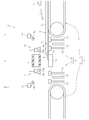
図1に示すように、ガラス板の製造装置1(以下、単に製造装置1と表記)は、保護シート2上に載置されたガラス板3を搬送方向Vに搬送する搬送機構4と、搬送経路上の切断領域Cに順々に搬入されるガラス板3の先頭部3aおよび最後部3bを不要部として折割って切断する切断機構5と、切断後の両不要部3a,3bを搬送経路外の廃棄領域まで移送する移送機構6と、切断領域Cに搬入された先頭部3aを指向してガスG(図2を参照)を噴射する噴射手段7とを備える。
ここで、製造装置1によって両不要部3a,3bを切断されるガラス板3は、平面視で矩形状に形成されている。このガラス板3には、前工程、すなわち、切断領域Cよりも搬送経路の上流側において、折割りの起点となるスクライブ線Sが二本形成される。二本のうちの先頭部3a側のスクライブ線Sは、先頭部3aを折割る起点となり、最後部3b側のスクライブ線Sは、最後部3bを折割る起点となる。いずれのスクライブ線Sも、搬送方向Vに直交する幅方向(図1では紙面に鉛直な方向であり、以下、単に幅方向と表記)に沿って形成される。また、ガラス板3における先頭部3aと最後部3bとの相互間に存する部位は、後に製品となる製品部3cである。なお、製造装置1に対しては、複数枚のガラス板3が、所定の間隔で順に搬入されてくる。
保護シート2は、ガラス板3よりも面積の大きい矩形状に形成されており、平面視でガラス板3の外周輪郭の全周から保護シート2が食み出した状態となっている。
搬送機構4は、切断領域Cを基準として搬送経路の上流側に配置された第一コンベア8と、下流側に配置された第二コンベア9とを備える。両コンベア8,9の各々は、ガラス板3を平置きで搬送することが可能である。また、両コンベア8,9は、ガラス板3の四辺のうち、平行な二辺が搬送方向Vと平行に延びるようにガラス板3を積載した状態で搬送を行う。
切断機構5は、ガラス板3の搬送経路上に設けられた切断領域Cに配置されている。この切断機構5は、切断領域C内において相対的に上流側に配置され、先頭部3aを切断するための第一切断機構10と、相対的に下流側に配置され、最後部3bを切断するための第二切断機構11とを備える。
第一切断機構10は、先頭部3aの折割時にガラス板3を下方から支持する一対の支持部材12,12と、移送機構6に近い側の支持部材12と協働して折割時のガラス板3を厚み方向に挟持する押え部材13a、及び、切断後の先頭部3aを吸着した状態で移動させて移送機構6に受け渡す吸着パッド群13b(吸着手段)を保持したアーム13と、移送機構6から遠い側の支持部材12と協働して折割時のガラス板3を厚み方向に挟持すると共に、折割りで発生したガラス粉を吸引する吸引ノズル14と、折割時に両支持部材12,12の間から上方に突出し、ガラス板3におけるスクライブ線Sの形成部を下方から押圧する折割バー15とを備える。
一対の支持部材12,12は、搬送方向Vに沿って間隔を空けて設置されると共に、各支持部材12が幅方向に沿って延びるよう設置されている。両支持部材12,12は、ガラス板3の先頭部3aの折割時において、スクライブ線Sの形成部を挟んで一方が先頭部3aを支持し、他方が製品部3cを支持する。
各支持部材12は、その上端部から上方にガス(図示省略)を噴射することが可能となっている。ガスは、搬送中のガラス板3が各支持部材12上を移動している間は継続して噴射される。これにより、各支持部材12上でガラス板3を浮上させた状態で搬送することが可能である。一方、ガスは、切断領域Cに搬入された先頭部3aを折割って切断するにあたり、ガラス板3の搬送を停止させた際には噴射が停止される。これにより、ガラス板3が各支持部材12上で浮上した状態が解除される。
アーム13は、上下方向、及び、搬送経路(搬送方向V)に平行な方向に動作することが可能となっている。これにより、アーム13は、押え部材13aによるガラス板3の挟持、及び、吸着パッド群13bによる先頭部3aの吸着を開始するための第一位置(図1に実線で示す位置)と、先頭部3aを吸着パッド群13bから移送機構6に受け渡すための第二位置(図1に二点鎖線で示す位置)との間を移動することが可能である。
押え部材13aと吸着パッド群13bとの両者は、アーム13に保持された状態の下で相互に独立して昇降動作が可能である。
押え部材13aは、アーム13が第一位置に位置した際に、初期位置(図1に破線で示す位置)と挟持位置(図1に実線で示す位置)との間を移動することが可能であると共に、挟持位置にて挟持のためにガラス板3を上方から押えることが可能となっている。
吸着パッド群13bは、複数の吸着パッドが幅方向に沿って並べられてなる。この吸着パッド群13bは、アーム13が第一位置に位置した際に、初期位置(図1に実線で示す位置)と吸着開始位置(図1に破線で示す位置)との間を移動することが可能であると共に、吸着開始位置にて先頭部3aの吸着を開始することが可能となっている。
ここで、アーム13が第一位置に位置した際の押え部材13aと吸着パッド群13bとの動作について説明する。
押え部材13aと吸着パッド群13bとの両者は、先頭部3aが切断領域Cに搬入される前の時点では、共に初期位置にて待機している。その後、先頭部3aが切断領域Cに搬入されてガラス板3の搬送が停止されると、押え部材13aが初期位置から挟持位置に移動してガラス板3(先頭部3a)を支持部材12と協働して挟持する。その後、先頭部3aが折割られて切断されると、押え部材13aが挟持位置から初期位置に復帰すると共に、吸着パッド群13bが初期位置から吸着開始位置に移動し、吸着によって先頭部3aを保持する。
一方、吸着パッド群13bが先頭部3aを吸着した後、アーム13が第一位置から移動して第二位置に位置した際には、吸着パッド群13bが先頭部3aの吸着を解除して移送機構6に先頭部3aを受け渡す。なお、先頭部3aを受け渡した後には、アーム13は第二位置から第一位置に復帰すると共に、押え部材13aと吸着パッド群13bとの両者は初期位置で次のガラス板3の先頭部3aが切断領域Cに搬入されるまで待機する。
吸引ノズル14は、幅方向に沿って延びるように設置されている。また、吸引ノズル14は、挟持のためにガラス板3を上方から押える押え部14aを有する。この吸引ノズル14は、折割時におけるガラス板3の挟持、及び、ガラス粉の吸引を行うための挟持吸引位置(図1に実線で示す位置)と、挟持吸引位置から上方に離間した待機位置(図1に二点鎖線で示す位置)との間を移動することが可能である。なお、本実施形態では、吸引ノズル14が押え部14aを有するが、吸引ノズル14から押え部14aを分離させ、独立した部材としてもよい。あるいは、吸引ノズル14を省略し、押え部14aのみを用いてもよい。
吸引ノズル14は、先頭部3aが切断領域Cに搬入される前の時点では、待機位置で待機している。その後、先頭部3aが切断領域Cに搬入されてガラス板3の搬送が停止されると、挟持吸引位置に移動して押え部14aがガラス板3(製品部3c)を支持部材12と協働して挟持する。また、挟持吸引位置に移動した吸引ノズル14は、ガラス粉を吸引するべく負圧を発生させて吸引を開始する。なお、ガラス粉を吸引した後の吸引ノズル14は、再び挟持吸引位置から待機位置に移動し、待機位置で次のガラス板3の先頭部3aが切断領域Cに搬入されるまで待機する。
折割バー15は、幅方向に沿って延びるように設置されている。折割バー15は、スクライブ線Sの形成部を押圧するための押圧位置(図1に実線で示す位置)と、押圧位置から下方に退避した退避位置(図1に二点鎖線で示す位置)との間を昇降することが可能である。
折割バー15は、先頭部3aが切断領域Cに搬入される前の時点では、退避位置に位置している。その後、先頭部3aが切断領域Cに搬入されてガラス板3の搬送が停止されると、押圧位置まで上昇してスクライブ線Sの形成部の押圧を行う。これにより、スクライブ線Sの形成部が湾曲し、スクライブ線Sを起点に先頭部3aが折割られる。なお、先頭部3aを切断した後の折割バー15は、再び押圧位置から退避位置に降下し、退避位置で次のガラス板3の先頭部3aが切断領域Cに搬入されるまで待機する。
第二切断機構11は、第一切断機構10と略同一な構成を有しており、第一切断機構10との相違点は、ガラス板3の先頭部3aではなく最後部3bを切断するように構成されている点のみである。そのため、図1に示す第二切断機構11に対して、第一切断機構10に付したものと同一の符号を付すことで重複する説明を省略する。
なお、第一切断機構10と第二切断機構11との間には、第一切断機構10に備わった一対の支持部材12,12から、第二切断機構11に備わった一対の支持部材12,12にガラス板3を移乗させるためのガイド部材16が配置されている。このガイド部材16により、搬送中のガラス板3が移送機構6の下方を潜って通過することが可能である。また、ガイド部材16は、その上端部から上方にガス(図示省略)を噴射することが可能となっている。ガスは、搬送中のガラス板3がガイド部材16上を移動している間は継続して噴射される。これにより、ガイド部材16上でガラス板3を浮上させた状態でガラス板3を搬送することが可能である。
ここで、本実施形態では、切断機構5が第一切断機構10と第二切断機構11との双方を備える構成となっているが、これに限定されるものではない。例えば、切断機構5が両切断機構10,11の一方のみを備える構成とし、この機構のみにより両不要部3a,3bの切断、及び、切断後の両不要部3a,3bの移送機構6への受け渡しを行うようにしてもよい。また、本実施形態では、折割りによる切断でガラス板3から両不要部3a,3bを切断する構成となっているが、例えば、レーザーによる切断で両不要部3a,3bを切断する構成としてもよい。
移送機構6は、本実施形態において、第一切断機構10と第二切断機構11との相互間に配置されたベルトコンベアである。
移送機構6が両不要部3a,3bを移送する移送経路は、切断領域C内における両切断機構10,11の相互間が経路の上流端となっている。また、移送経路は、ガラス板3の搬送経路よりも上方に位置し、且つ、搬送経路と直交して交差する方向に延びている。これにより、移送機構6によって両不要部3a,3bを切断領域Cから搬出する際の高さ位置が、搬送機構4によって両不要部3a,3bを切断領域Cに搬入する際の高さ位置よりも高くなっている。移送経路の下流端には、切断後の両不要部3a,3bの廃棄領域としての廃棄ボックス(図示省略)が備わっている。
移送機構6は、当該移送機構6上に切断後の先頭部3aおよび最後部3bのいずれも存在しない状態では稼働を停止しており、第一切断機構10に備わった吸着パッド群13b(第二切断機構11に備わった吸着パッド群13b)により、切断後の先頭部3a(最後部3b)が移送機構6に受け渡されることで稼働を開始する。その後、移送機構6上に存在する先頭部3aおよび最後部3bの全てが、移送経路の下流端の廃棄ボックスに廃棄されるまで継続して稼働する。
ここで、本実施形態においては、移送機構6としてベルトコンベアを用いているが、この他、ローラーコンベアやロボットアーム等を用いてもよい。さらに、第一切断機構10の吸着パッド群13b、及び、第二切断機構11の吸着パッド群13bの各々に、移送機構としての機能を付与しても構わない。すなわち、両吸着パッド群13b,13bが、それぞれ切断後の先頭部3aおよび最後部3bを吸着した状態で廃棄ボックスまで移送する構成としてもよい。
また、本実施形態では、移送機構6が第一切断機構10と第二切断機構11との相互間に配置されると共に、移送経路の上流端が切断領域C内における両切断機構10,11の相互間に位置しているが、この限りではない。例えば、切断領域C外に移送機構6を配置し、切断領域C外に移送経路の上流端を位置させてもよい。より具体的には、本実施形態の移送経路の上流端を幅方向に移動させることにより、切断領域C外に移送経路の上流端を位置させてもよい。このように切断領域C外に移送経路の上流端を位置させる場合には、切断領域Cと移送経路の上流端とが可及的に近接するように移送機構6を配置することが好ましい。また、この場合には、本実施形態とは異なり、移送経路とガラス板3の搬送経路とを同一高さに位置させてもよい。
また、本実施形態においては、移送経路がガラス板3の搬送経路と直交して交差する方向に延びているが、この限りではない。搬送経路外の廃棄領域まで両不要部3a,3bを移送できる経路であれば、移送経路がどのような方向に延びていても構わない。なお、両不要部3a,3bの廃棄領域は、搬送経路外であれば任意の位置に配置してよい。
噴射手段7は、本実施形態において、水平面に対して傾斜した姿勢でガラス板3の搬送経路よりも上方に配置された噴射ノズルである。この噴射手段7は、搬送経路の下流側に向けてガスG(例えば、空気等)を噴射することが可能である。噴射手段7は、ガラス板3の先頭部3aが切断領域C内で停止している際のみガスGを噴射する。なお、噴射手段7としては、噴射ノズルの他、送風ファン等を用いてもよい。
以下、上記のガラス板の製造装置1を用いた本発明の実施形態に係るガラス板の製造方法について説明する。
はじめに、前工程にて所定の処理を施したガラス板3を第一コンベア8により搬送経路の下流側(搬送方向V)に送っていく。その後、ガラス板3の一部を先頭部3a側から一対の支持部材12,12上に移乗させていく。このとき、各支持部材12の上端部からガスを噴射し、各支持部材12上でガラス板3を浮上させた状態で搬送する。必要に応じ、ガイド部材16の上端部からもガスを噴射し、ガイド部材16上でガラス板3を浮上させた状態で搬送する。
そして、図2に示すように、ガラス板3におけるスクライブ線S(先頭部3aを折割るための起点)の形成部が、第一切断機構10に備わった折割バー15の真上に到達した時点で、第一コンベア8によるガラス板3の搬送を停止する。これにより、切断領域Cに搬入されたガラス板3の先頭部3aも停止する。このとき、各支持部材12の上端部からのガスの噴射も停止し、ガラス板3が各支持部材12上で浮上した状態を解除する。ガイド部材16の上端部からもガスを噴射している場合には、このガスの噴射も停止する。
なお、先頭部3aが切断領域Cに搬入された時点において、図2に二点鎖線で示すように、先頭部3aから食み出た保護シート2が、先頭部3aの上面を覆った状態となっている場合がある。この先頭部3aの上面を覆った保護シート2は、噴射手段7から先頭部3aを指向してガスGを噴射することで、ガスGの圧力により上面上から押し退ける。
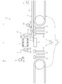
次いで、図3に示すように、第一切断機構10の押え部材13a、及び、吸引ノズル14を、それぞれ挟持位置、及び、挟持吸引位置に移動させる。これにより、一対の支持部材12,12、押え部材13a、及び、吸引ノズル14の押え部14aでガラス板3を厚み方向に挟持する。
そして、ガラス板3を挟持した状態の下、第一切断機構10の折割バー15を押圧位置まで移動させ、ガラス板3におけるスクライブ線Sの形成部を下方から押圧することにより、先頭部3aを折割って切断する。折割りで発生したガラス粉は、吸引ノズル14により吸引する。
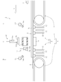
次いで、図4に示すように、押え部材13aを挟持位置から初期位置に復帰させると共に、吸着パッド群13bを初期位置から吸着開始位置に移動させ、切断後の先頭部3aの吸着を開始する。押え部材13aと吸着パッド群13bとの両者に、これらの動作を行わせている間には、吸引ノズル14を挟持吸引位置から待機位置に移動させると共に、折割バー15を押圧位置から退避位置に移動させる。
次いで、図5に示すように、切断後の先頭部3aを吸着パッド群13bに吸着させた状態の下で、アーム13を第一位置から第二位置まで移動させる。そして、アーム13が第二位置に到達すると、吸着パッド群13bに先頭部3aの吸着を解除させることにより、先頭部3aを移送機構6に備わったベルトに受け渡す。この受け渡しが完了すると、移送機構6が稼働を開始して、先頭部3aを移送経路の下流端に備わった廃棄ボックスまで移送して廃棄する。
アーム13が第一位置から第二位置まで移動している間には、搬送経路(搬送方向V)に沿ったガラス板3の搬送を再開する。なお、搬送の再開に伴い、第一切断機構10の両支持部材12,12上、ガイド部材16上、及び、第二切断機構11の両支持部材12,12上をガラス板3が搬送される間は、各支持部材12及びガイド部材16上でガラス板3を浮上させた状態で搬送する。
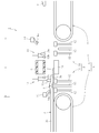
次いで、図6に示すように、ガラス板3におけるスクライブ線S(最後部3bを折割るための起点)の形成部が、第二切断機構11に備わった折割バー15の真上に到達した時点で、第二コンベア9によるガラス板3の搬送を停止する。これにより、切断領域Cに搬入されたガラス板3の最後部3bも停止する。このとき、ガラス板3が各支持部材12及びガイド部材16上で浮上した状態も解除する。
そして、第一切断機構10による先頭部3aの切断と同様にして、第二切断機構11による最後部3bの切断を行う。さらに、図7に示すように、第一切断機構10の吸着パッド群13bによる移送機構6への先頭部3aの受け渡しと同様にして、第二切断機構11の吸着パッド群13bによる移送機構6への最後部3bの受け渡しを行う。この受け渡しが完了すると、移送機構6は、先頭部3aと同様にして、最後部3bを廃棄ボックスまで移送して廃棄する。
先頭部3aおよび最後部3bを切断された後のガラス板3は、第二コンベア9により更に搬送経路(搬送方向V)の下流側に送られ、後工程にて所定の処理(例えば端面加工や洗浄)を施される。以上により、本実施形態に係るガラス板の製造方法の全工程が完了する。
以下、上記の製造装置1、及び、製造装置1を用いた製造方法による主たる作用・効果について説明する。
上記の製造装置1、及び、製造装置1を用いた製造方法では、先頭部3aと最後部3bとをガラス板3の搬送に伴って順々に搬送経路上の共通の切断領域Cに搬入して切断する。これにより、先頭部3aを切断するための領域と、最後部3bを切断するための領域とを別々に設ける必要がなくなり、省スペース化を図ることが可能となる。その上、両不要部3a,3bを共通の移送機構6を利用して廃棄領域まで移送する。これにより、先頭部3aを移送するための機構の設置スペースと、最後部3bを移送するための機構の設置スペースとの双方を確保する必要がなくなり、より省スペース化を図ることができる。加えて、共通の移送機構6についてのみ保守、点検等を行えばよいので、これらの作業に要するコストを削減できる。
1 ガラス板の製造装置
2 保護シート
3 ガラス板
3a 先頭部
3b 最後部
4 搬送機構
5 切断機構
6 移送機構
10 第一切断機構
11 第二切断機構
13b 吸着パッド群
C 切断領域
G ガス
V 搬送方向
2 保護シート
3 ガラス板
3a 先頭部
3b 最後部
4 搬送機構
5 切断機構
6 移送機構
10 第一切断機構
11 第二切断機構
13b 吸着パッド群
C 切断領域
G ガス
V 搬送方向
Claims (7)
- ガラス板の搬送経路上で該ガラス板から第一不要部および第二不要部を切断した後、前記両不要部を前記搬送経路外の廃棄領域まで移送して廃棄する工程を含んだガラス板の製造方法であって、
前記搬送経路上に前記両不要部の切断を行う共通の切断領域を設け、前記ガラス板の搬送に伴って前記両不要部を順々に前記切断領域に搬入して切断すると共に、
切断後の前記両不要部を共通の移送機構を利用して前記廃棄領域まで移送することを特徴とするガラス板の製造方法。 - 前記第一不要部が前記ガラス板の搬送方向の先頭部であると共に、前記第二不要部が前記ガラス板の搬送方向の最後部であり、
前記先頭部を前記切断領域に搬入して切断した後、前記最後部を前記切断領域に搬入して切断することを特徴とする請求項1に記載のガラス板の製造方法。 - 前記切断領域内にて相対的に前記搬送経路の上流側に配置され、且つ、前記先頭部を切断する第一切断機構と、相対的に前記搬送経路の下流側に配置され、且つ、前記最後部を切断する第二切断機構とを設け、
前記両切断機構の相互間から前記移送機構による切断後の前記両不要部の移送を開始することを特徴とする請求項2に記載のガラス板の製造方法。 - 前記移送機構として、前記第一切断機構と前記第二切断機構との相互間に配置されたコンベアを用いることを特徴とする請求項3に記載のガラス板の製造方法。
- 前記ガラス板を該ガラス板よりも面積の大きい保護シート上に載置した状態で搬送すると共に、切断後の前記先頭部を上面側から吸着手段により吸着した状態で移動させて前記移送機構に受け渡すに際し、
前記先頭部を前記切断領域に搬入した後で、且つ、該先頭部を切断する前に、
前記先頭部から搬送方向の前方側に食み出た前記保護シートに対し、前記搬送経路の下流側に向かう流れのガスを噴射することを特徴とする請求項2~4のいずれかに記載のガラス板の製造方法。 - 前記移送機構による移送に伴って切断後の前記両不要部を前記切断領域から搬出する際の高さ位置を、前記両不要部を前記切断領域に搬入する際の高さ位置よりも高くすることを特徴とする請求項5に記載のガラス板の製造方法。
- ガラス板を搬送経路に沿って搬送する搬送機構と、
前記搬送経路上の切断領域に配置され、且つ、該切断領域に順々に搬入される前記ガラス板の第一不要部および第二不要部を該ガラス板から切断する切断機構と、
切断後の前記両不要部を前記搬送経路外の廃棄領域まで移送する移送機構とを備えるガラス板の製造装置。
Priority Applications (2)
| Application Number | Priority Date | Filing Date | Title |
|---|---|---|---|
| CN201880016953.3A CN110402241B (zh) | 2017-03-16 | 2018-02-23 | 玻璃板的制造方法及制造装置 |
| KR1020197018449A KR102421585B1 (ko) | 2017-03-16 | 2018-02-23 | 유리판의 제조 방법 및 제조 장치 |
Applications Claiming Priority (2)
| Application Number | Priority Date | Filing Date | Title |
|---|---|---|---|
| JP2017051154A JP6891561B2 (ja) | 2017-03-16 | 2017-03-16 | ガラス板の製造方法および製造装置 |
| JP2017-051154 | 2017-03-16 |
Publications (1)
| Publication Number | Publication Date |
|---|---|
| WO2018168397A1 true WO2018168397A1 (ja) | 2018-09-20 |
Family
ID=63523868
Family Applications (1)
| Application Number | Title | Priority Date | Filing Date |
|---|---|---|---|
| PCT/JP2018/006687 Ceased WO2018168397A1 (ja) | 2017-03-16 | 2018-02-23 | ガラス板の製造方法および製造装置 |
Country Status (5)
| Country | Link |
|---|---|
| JP (1) | JP6891561B2 (ja) |
| KR (1) | KR102421585B1 (ja) |
| CN (1) | CN110402241B (ja) |
| TW (1) | TWI744500B (ja) |
| WO (1) | WO2018168397A1 (ja) |
Cited By (2)
| Publication number | Priority date | Publication date | Assignee | Title |
|---|---|---|---|---|
| CN112390518A (zh) * | 2019-08-14 | 2021-02-23 | 塔工程有限公司 | 划线装置的控制方法 |
| CN113396131A (zh) * | 2019-04-22 | 2021-09-14 | 日本电气硝子株式会社 | 玻璃板的制造装置以及制造方法 |
Families Citing this family (2)
| Publication number | Priority date | Publication date | Assignee | Title |
|---|---|---|---|---|
| WO2021131559A1 (ja) * | 2019-12-24 | 2021-07-01 | 日本電気硝子株式会社 | ガラスフィルムの製造方法、ガラスロールの製造方法、及びガラスフィルムの製造装置 |
| KR102650505B1 (ko) * | 2022-04-11 | 2024-03-22 | 주식회사 시스템알앤디 | 절단면 강도를 보존하는 초박형유리가공품 피킹 장치 및 방법 |
Citations (5)
| Publication number | Priority date | Publication date | Assignee | Title |
|---|---|---|---|---|
| US20100162758A1 (en) * | 2007-09-13 | 2010-07-01 | Grenzebach Maschinenbau Gmbh | Device and method for severing a continuous glass strip |
| JP2015013782A (ja) * | 2013-07-08 | 2015-01-22 | 三星ダイヤモンド工業株式会社 | 貼り合わせ基板のブレイク装置 |
| JP2016503379A (ja) * | 2012-11-09 | 2016-02-04 | コーニング インコーポレイテッド | ガラスリボンを処理する方法 |
| JP2018039703A (ja) * | 2016-09-08 | 2018-03-15 | 三星ダイヤモンド工業株式会社 | 端材除去装置 |
| JP2018043421A (ja) * | 2016-09-15 | 2018-03-22 | 三星ダイヤモンド工業株式会社 | 端材除去装置 |
Family Cites Families (9)
| Publication number | Priority date | Publication date | Assignee | Title |
|---|---|---|---|---|
| WO2002057192A1 (en) * | 2001-01-17 | 2002-07-25 | Mitsuboshi Diamond Industrial Co., Ltd. | Separator and separating system |
| DE102007008634B3 (de) * | 2007-02-16 | 2008-08-07 | Jenoptik Automatisierungstechnik Gmbh | Verfahren und Vorrichtung zum Trennen von Verbundglasscheiben |
| JP5796421B2 (ja) * | 2011-09-02 | 2015-10-21 | 日本電気硝子株式会社 | 板ガラス割断装置 |
| CN103946169B (zh) * | 2011-11-16 | 2017-10-24 | 日本电气硝子株式会社 | 板玻璃切断装置、板玻璃切断方法、板玻璃制作方法、及板玻璃切断系统 |
| KR20150084758A (ko) * | 2012-11-13 | 2015-07-22 | 니폰 덴키 가라스 가부시키가이샤 | 판 유리의 제조 방법 및 제조 장치 |
| US9434085B2 (en) * | 2013-06-04 | 2016-09-06 | Shenzhen China Star Optoelectronics Technology Co., Ltd | Cutting system for glass substrate |
| JP6136070B2 (ja) * | 2013-08-28 | 2017-05-31 | 日本電気硝子株式会社 | ガラスフィルムリボン製造方法及びガラスフィルムリボン製造装置 |
| CN104628246B (zh) * | 2013-11-14 | 2019-07-05 | 塔工程有限公司 | 划线装置及划线方法 |
| JP6420648B2 (ja) * | 2014-12-05 | 2018-11-07 | 川崎重工業株式会社 | ガラス板の割断装置 |
-
2017
- 2017-03-16 JP JP2017051154A patent/JP6891561B2/ja active Active
-
2018
- 2018-02-23 CN CN201880016953.3A patent/CN110402241B/zh active Active
- 2018-02-23 KR KR1020197018449A patent/KR102421585B1/ko active Active
- 2018-02-23 WO PCT/JP2018/006687 patent/WO2018168397A1/ja not_active Ceased
- 2018-03-08 TW TW107107857A patent/TWI744500B/zh active
Patent Citations (5)
| Publication number | Priority date | Publication date | Assignee | Title |
|---|---|---|---|---|
| US20100162758A1 (en) * | 2007-09-13 | 2010-07-01 | Grenzebach Maschinenbau Gmbh | Device and method for severing a continuous glass strip |
| JP2016503379A (ja) * | 2012-11-09 | 2016-02-04 | コーニング インコーポレイテッド | ガラスリボンを処理する方法 |
| JP2015013782A (ja) * | 2013-07-08 | 2015-01-22 | 三星ダイヤモンド工業株式会社 | 貼り合わせ基板のブレイク装置 |
| JP2018039703A (ja) * | 2016-09-08 | 2018-03-15 | 三星ダイヤモンド工業株式会社 | 端材除去装置 |
| JP2018043421A (ja) * | 2016-09-15 | 2018-03-22 | 三星ダイヤモンド工業株式会社 | 端材除去装置 |
Cited By (4)
| Publication number | Priority date | Publication date | Assignee | Title |
|---|---|---|---|---|
| CN113396131A (zh) * | 2019-04-22 | 2021-09-14 | 日本电气硝子株式会社 | 玻璃板的制造装置以及制造方法 |
| CN113396131B (zh) * | 2019-04-22 | 2023-09-26 | 日本电气硝子株式会社 | 玻璃板的制造装置以及制造方法 |
| CN112390518A (zh) * | 2019-08-14 | 2021-02-23 | 塔工程有限公司 | 划线装置的控制方法 |
| CN112390518B (zh) * | 2019-08-14 | 2023-01-31 | 塔工程有限公司 | 划线装置的控制方法 |
Also Published As
| Publication number | Publication date |
|---|---|
| TWI744500B (zh) | 2021-11-01 |
| TW201834984A (zh) | 2018-10-01 |
| JP6891561B2 (ja) | 2021-06-18 |
| JP2018154513A (ja) | 2018-10-04 |
| KR20190126286A (ko) | 2019-11-11 |
| KR102421585B1 (ko) | 2022-07-15 |
| CN110402241B (zh) | 2021-11-05 |
| CN110402241A (zh) | 2019-11-01 |
Similar Documents
| Publication | Publication Date | Title |
|---|---|---|
| WO2018168397A1 (ja) | ガラス板の製造方法および製造装置 | |
| KR101385790B1 (ko) | 광학 필름의 반송 방법 및 이를 이용한 장치 | |
| JP2014022744A (ja) | 非接触マルチ搬送装置及びそれを用いた異物除去方法 | |
| JP6140012B2 (ja) | 貼り合わせ基板のブレイク方法 | |
| KR101865601B1 (ko) | 판 유리 할단 장치 | |
| JP4388493B2 (ja) | ガラス基板用フイルムの貼付方法 | |
| KR20040031614A (ko) | 워크 배치 장치 | |
| JP5583478B2 (ja) | パネルの折割装置 | |
| CN105270889A (zh) | 脆性材料基板的搬送方法及搬送装置 | |
| JP2017071224A (ja) | 基板加工装置 | |
| JP2001235734A (ja) | 液晶パネルの折割装置 | |
| KR20190013499A (ko) | 분진 비산 방지 장치 그리고 이 분진 비산 방지 장치를 구비한 기판 가공 장치 | |
| KR20190013479A (ko) | 스크라이브 장치 | |
| JP2014151538A (ja) | 基板加工装置 | |
| JP6029087B2 (ja) | 板ガラス物品の分離装置 | |
| JP3564307B2 (ja) | 枚葉印刷機の給紙装置 | |
| JP2017024419A (ja) | スクライブ装置 | |
| CN104162908B (zh) | 具有清洁功能的板材切断装置 | |
| TWI659914B (zh) | Substrate processing device | |
| JP2017074786A (ja) | 基板加工装置 | |
| KR20190013480A (ko) | 브레이크장치 | |
| JP2000191333A (ja) | ガラス板の搬送方法及びその装置 | |
| JP2015017014A (ja) | 貼り合わせ基板のブレイク装置 | |
| JP2019026513A (ja) | 粉塵飛散防止装置並びにこの粉塵飛散防止装置を備えた基板加工装置 | |
| JP2020075381A (ja) | ブレイク装置 |
Legal Events
| Date | Code | Title | Description |
|---|---|---|---|
| 121 | Ep: the epo has been informed by wipo that ep was designated in this application |
Ref document number: 18768614 Country of ref document: EP Kind code of ref document: A1 |
|
| ENP | Entry into the national phase |
Ref document number: 20197018449 Country of ref document: KR Kind code of ref document: A |
|
| NENP | Non-entry into the national phase |
Ref country code: DE |
|
| 122 | Ep: pct application non-entry in european phase |
Ref document number: 18768614 Country of ref document: EP Kind code of ref document: A1 |