WO2018168366A1 - ガラス板の製造方法 - Google Patents
ガラス板の製造方法 Download PDFInfo
- Publication number
- WO2018168366A1 WO2018168366A1 PCT/JP2018/006252 JP2018006252W WO2018168366A1 WO 2018168366 A1 WO2018168366 A1 WO 2018168366A1 JP 2018006252 W JP2018006252 W JP 2018006252W WO 2018168366 A1 WO2018168366 A1 WO 2018168366A1
- Authority
- WO
- WIPO (PCT)
- Prior art keywords
- scribe line
- original plate
- trigger
- glass
- glass original
- Prior art date
- Legal status (The legal status is an assumption and is not a legal conclusion. Google has not performed a legal analysis and makes no representation as to the accuracy of the status listed.)
- Ceased
Links
Images







Classifications
-
- B—PERFORMING OPERATIONS; TRANSPORTING
- B26—HAND CUTTING TOOLS; CUTTING; SEVERING
- B26F—PERFORATING; PUNCHING; CUTTING-OUT; STAMPING-OUT; SEVERING BY MEANS OTHER THAN CUTTING
- B26F3/00—Severing by means other than cutting; Apparatus therefor
-
- B—PERFORMING OPERATIONS; TRANSPORTING
- B28—WORKING CEMENT, CLAY, OR STONE
- B28D—WORKING STONE OR STONE-LIKE MATERIALS
- B28D5/00—Fine working of gems, jewels, crystals, e.g. of semiconductor material; apparatus or devices therefor
-
- C—CHEMISTRY; METALLURGY
- C03—GLASS; MINERAL OR SLAG WOOL
- C03B—MANUFACTURE, SHAPING, OR SUPPLEMENTARY PROCESSES
- C03B33/00—Severing cooled glass
- C03B33/02—Cutting or splitting sheet glass or ribbons; Apparatus or machines therefor
- C03B33/023—Cutting or splitting sheet glass or ribbons; Apparatus or machines therefor the sheet or ribbon being in a horizontal position
- C03B33/033—Apparatus for opening score lines in glass sheets
-
- C—CHEMISTRY; METALLURGY
- C03—GLASS; MINERAL OR SLAG WOOL
- C03B—MANUFACTURE, SHAPING, OR SUPPLEMENTARY PROCESSES
- C03B33/00—Severing cooled glass
- C03B33/02—Cutting or splitting sheet glass or ribbons; Apparatus or machines therefor
- C03B33/023—Cutting or splitting sheet glass or ribbons; Apparatus or machines therefor the sheet or ribbon being in a horizontal position
- C03B33/037—Controlling or regulating
Definitions
- the present invention is a glass comprising: a scribe line forming step for forming a scribe line on a glass original plate; and a cutting step for cutting the glass original plate on which the scribe line is formed in the scribe line formation step using the scribe line.
- the present invention relates to a method for manufacturing a plate.
- a method of obtaining one or a plurality of glass plates by cutting a glass original plate there is a method of obtaining one or a plurality of glass plates by cutting a glass original plate.
- a method in which bending stress is generated by an external force on the glass original plate on which the scribe line is formed and the glass original plate is cleaved along the scribe line is widely used.
- the scribe line formed on the glass original plate by this method is usually accompanied by a crack in the thickness direction called a median crack (longitudinal crack).
- the glass plate may be transported between the step of forming a scribe line on the glass plate and the step of cutting the glass plate.
- the glass original plate may be cut along the scribe line due to an impact or the like during conveyance or the like.
- the scribe line forming step it is conceivable to form a scribe line not accompanied by a median crack, and to perform a process for generating a median crack in the scribe line after transport or the like (for example, patents) Reference 1).
- the scribe line without median cracks will not be cut unexpectedly during transportation before the cutting process because the glass slab will never be cut along the scribe line even if impact is applied. The situation where it is done can be avoided.
- a scribe line that is connected to a scribe line not accompanied by a median crack and is accompanied by a median crack (hereinafter, such a scribe line is referred to as a trigger scribe line) is formed on a glass original plate, and this glass original plate is triggered by a scribe scribe line. Cleaving along the line.
- the median crack is generated in the scribe line not accompanied by the median crack, and the glass original plate can be cleaved along the scribe line.
- the scribe line to which the trigger scribe line is connected does not intersect with the scribe line not accompanied by other median cracks. That is, in this process, the cleaving along the trigger scribe line is used to cleave along the scribe line that does not intersect (without median crack).
- an object of the present invention is to improve the production efficiency of a glass plate in the case of using a cleaving along a trigger scribe line for cutting the glass original plate.
- the glass plate manufacturing method of the present invention created to solve the above problems includes a scribe line forming step for forming a scribe line on a glass original plate, and the glass original plate after the scribe line formation step.
- the scribe line forming step includes forming a first scribe line on the one main surface of the glass original plate, and forming the first scribe line on the main surface after the first scribe line forming step.
- a second scribe line forming step of forming the second scribe line intersecting the first scribe line After the second scribe line forming step, a step is formed on the main surface of the second scribe line, the trigger scribe line connected to the terminal side of the first scribe line and accompanied by a median crack.
- a trigger scribe line forming step is provided.
- the first scribe line and the second scribe line not accompanied by the median crack are obtained by, for example, plastically deforming the glass original plate by sliding the chip with respect to the region excluding the peripheral portion on the main surface of the glass original plate. Can be formed.
- the trigger scribe line accompanied by the median crack for example, rolls and slides the wheel cutter with respect to the main surface of the glass original plate, or slides the chip so as to reach the peripheral portion with respect to the main surface of the glass original plate. It can be formed by moving it.
- the glass original plate can be cut along the trigger scribe line. Further, since the trigger scribe line is connected to the second scribe line, when the glass original plate is cleaved along the trigger scribe line, a median crack occurs in the second scribe line. Therefore, the glass original plate cleaved along the trigger scribe line can be cleaved along the second scribe line.
- the second scribe line intersects the first scribe line, when the glass original plate is cleaved along the second scribe line, a median crack occurs in the first scribe line, and the glass The original plate can be cleaved along the first scribe line.
- the glass original plate can be cut along these scribe lines in the order of the trigger scribe line, the second scribe line, and the first scribe line. That is, in order to cut
- the 1st scribe line and 2nd scribe line which are formed in the glass original plate do not accompany a median crack. Accordingly, even when the glass original plate is conveyed between the second scribe line forming step and the trigger scribe line forming step, the glass original plate is cut along the first scribe line and the second scribe line during the conveyance and the like. Can be avoided.
- the cutting step includes a first cleaving step of cleaving along the trigger scribe line the glass original plate on which the trigger scribe line is formed in the trigger scribe line forming step, and the first cleaving step. Cleaving along the first scribe line the second cleaving step of cleaving the glass original plate cut in the process along the second scribe line, and cleaving the glass original plate cleaved in the second cleaving step. And a third cleaving step.
- the pair of first scribe lines are formed in parallel with each other
- the pair of second scribe lines are formed in parallel with each other.
- it may be formed to be orthogonal to the first scribe line.
- the production efficiency of the glass plate can be improved.
- FIG. 1 is a flowchart showing main steps of a glass plate manufacturing method 1 according to an embodiment of the present invention.
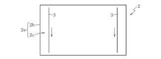
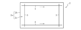
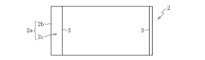
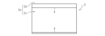
- 2A to 2C are schematic plan views showing the glass original plate 2 on which scribe lines are formed.
- the manufacturing method 1 of a glass plate manufactures a rectangular glass plate by cut
- FIG. 1 is a flowchart showing main steps of a glass plate manufacturing method 1 according to an embodiment of the present invention.
- 2A to 2C are schematic plan views showing the glass original plate 2 on which scribe lines are formed.
- the manufacturing method 1 of a glass plate manufactures a rectangular glass plate by cut
- the glass plate manufacturing method 1 includes a scribe line forming step S1, a conveying step S2, and a cutting step S3.
- scribe lines are formed on the glass original plate 2.
- conveyance process S2 the glass original plate 2 in which the said scribe line was formed in scribe line formation process S1 is conveyed.
- cutting process S3 the glass original plate 2 conveyed by conveyance process S2 is cut
- the glass base plate 2 for example, silicate glass, silica glass, borosilicate glass, or alkali-free glass is used.
- the alkali-free glass is a glass that does not substantially contain an alkali component (alkali metal oxide), and specifically, a glass having an alkali component of 3000 ppm or less.
- the plate thickness of the glass original plate 2 is, for example, 50 ⁇ m to 1 mm.
- the scribe line forming step S1 includes a first scribe line forming step S11 and a second scribe line forming step S12.
- a pair of first scribe lines 3 and 3 are indicated by black arrows in the intermediate region 2c excluding the peripheral edge 2b on one main surface 2a of the glass original plate 2. It is formed in the direction shown.
- the pair of first scribe lines 3 and 3 are parallel to each other.
- the pair of first scribe lines 3, 3 are parallel to the short side of the glass original plate 2.
- the pair of first scribe lines 3, 3 is formed in the intermediate region 2c where the pair of first scribe lines 3, 3 is formed in the first scribe line forming step S11.
- a pair of second scribe lines 4, 4 orthogonal to 3 are formed in a direction indicated by a black arrow.
- the pair of second scribe lines 4 and 4 are parallel to each other.
- the pair of second scribe lines 4 and 4 are parallel to the long side of the glass original plate 2.
- the first scribe line 3 and the second scribe line 4 are formed, for example, by plastically deforming the glass original plate 2 by sliding a chip in the intermediate region 2c. As shown in FIG. 3A, the first scribe line 3 and the second scribe line 4 formed in this way are not accompanied by a median crack.
- the first scribe line 3 and the second scribe line 4 have a width of, for example, 10 ⁇ m to 60 ⁇ m and a depth of, for example, 10 ⁇ m to 60 ⁇ m.
- tip if a scribe line is formed only in the intermediate
- the cutting step S3 includes a trigger scribe line forming step S30, a first cutting step S31, a second cutting step S32, and a third cutting step S33.
- the main surface 2a on which the second scribe line 4 is formed in the second scribe line forming step S12 is more than the first scribe line 3 in the second scribe line 4.
- a trigger scribe line 5 orthogonal to the end side portion is formed in a direction indicated by a black arrow.
- the trigger scribe line 5 is parallel to the first scribe line 3.
- the trigger scribe line 5 may extend to the peripheral edge 2b (the long side of the glass original plate 2) of the main surface 2a of the glass original plate 2.
- the trigger scribe line 5 rolls and slides a wheel cutter with respect to the main surface 2a of the glass original plate 2 or slides the chip so as to reach the peripheral portion 2b with respect to the main surface 2a of the glass original plate 2. It is formed by moving.
- the trigger scribe line 5 may be formed only in the intermediate region 2c.
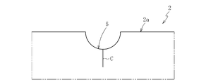
- the trigger scribe line 5 thus formed is accompanied by a median crack C as shown in FIG. 3B.
- the trigger scribe line 5 has, for example, a width of, for example, 30 ⁇ m to 80 ⁇ m and a depth of, for example, 30 ⁇ m to 80 ⁇ m.
- the glass original plate 2 can be cut along the trigger scribe line 5 in the state shown in FIG. 2C.
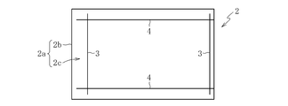
- the glass original plate 2 on which the trigger scribe line 5 is formed in the trigger scribe line forming step S30 is cleaved along the trigger scribe line 5. Specifically, the glass original plate 2 is split along the trigger scribe line 5. Then, the glass original plate 2 will be in the state shown to FIG. 4A. Since the trigger scribe line 5 intersects the second scribe line 4, when the glass original plate 2 is cleaved along the trigger scribe line 5, a median crack C occurs in the second scribe line 4. Therefore, in the state of FIG. 4A, the glass original plate 2 cleaved along the trigger scribe line 5 can be cleaved along the second scribe line 4.
- the glass original plate 2 cleaved in the first cleaving step S31 is cleaved along the second scribe line 4. Specifically, the glass original plate 2 is split along the second scribe line 4. Then, the glass original plate 2 will be in the state shown to FIG. 4B. Since the second scribe line 4 intersects with the first scribe line 3, when the glass original plate 2 is cleaved along the second scribe line 4, a median crack C is generated in the first scribe line 3, and FIG. In the state shown, the glass original plate 2 can be cleaved along the first scribe line 3.
- the glass original plate 2 cleaved in the second cleaving step is cleaved along the first scribe line 3. Specifically, the glass original plate 2 is split along the first scribe line 3. The glass original plate 2 will be in the state shown in FIG. 4C. In this state, the glass original plate 2 is the size of the glass plate to be manufactured.
- the glass original plate 2 can be cleaved along these scribe lines in the order of the trigger scribe line 5, the second scribe line 4, and the first scribe line 3. That is, in order to cut the glass original plate 2, it is possible to cleave along the intersecting first and second scribe lines 3 and 4 by cleaving along the trigger scribe line 5 once. As a result, the number of steps for cutting is reduced and the portion of the glass original plate 2 that cannot be used as a product is reduced as compared to the case where the cutting along the trigger scribe line 5 is required twice or more. , Glass production efficiency is improved. That is, according to the glass plate manufacturing method 1 of the present embodiment, when the cleaving along the trigger scribe line 5 is used for cutting the glass original plate 2, the production efficiency of the glass plate can be improved. It is.
- the trigger scribe line 5 is formed in the direction indicated by the black arrow so as to intersect the first scribe line 3 with respect to the glass plate manufacturing method 1 of this embodiment.
- the glass original plate 2 can be cleaved along the trigger scribe line 5.
- FIG. 5B when cleaving along the trigger scribe line 5, a median crack C is generated in the first scribe line 3, and the glass original plate 2 can be cleaved along the first scribe line 3.
- FIG. 5C even when cleaved along the first scribe line 3, the median crack C does not occur in the second scribe line 4, and the glass original plate 2 is cleaved along the second scribe line 4. There are many cases where this is not possible.
- the first scribe line 3 and the second scribe line 3 formed on the glass original plate 2 are between the second scribe line forming step S12 and the trigger scribe line forming step S30.
- the scribe line 4 is not accompanied by the median crack C. Therefore, it is possible to avoid a situation in which the glass original plate 2 is cut along the first scribe line 3 and the second scribe line 4 in the step (conveying step S2) between the scribe line forming step S1 and the cutting step S3.
- the second scribe line 4 that intersects the first scribe line 3 is formed after the first scribe line 3. Therefore, at the intersection of the first scribe line 3 and the second scribe line 4, the first scribe line 3 is in a state of being suppressed by the second scribe line 4, and the stress is high. Thereby, even if it cleaves along the 1st scribe line 3, the stress resulting from formation of the 1st scribe line 3 is not completely released in the intersection. As a result, it is considered that the median crack C does not occur in the second scribe line 4 and it is impossible to cleave along the second scribe line 4.
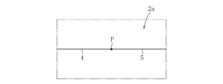
- the trigger scribe line 5 is orthogonal to the second scribe line 4, but the crossing angle may not be a right angle as shown in FIG. 6A.
- the trigger scribe line 5 only needs to be connected to the second scribe line 4, so it is not necessary for the trigger scribe line 5 to intersect the second scribe line 4, as shown in FIG. 6B.
- the intermediate part of the scribe line 5 may be connected only to the end part of the second scribe line 4, and the end part of the trigger scribe line 5 is connected to the end part of the second scribe line 4 as shown in FIG. 6C. It may be just connected.
- a black point P in FIGS. 6A to 6C indicates a part where the trigger scribe line 5 is connected to the second scribe line 4.
- first and second scribe lines 3 and 4 and the trigger scribe line 5 are all linear, but may be curved.
- the cleaving along the 1st and 2nd scribe lines 3 and 4 and the trigger scribe line 5 was performed by folding (generation
- the thermal stress may be generated by heating with a laser or the like.
Landscapes
- Chemical & Material Sciences (AREA)
- Engineering & Computer Science (AREA)
- Materials Engineering (AREA)
- Organic Chemistry (AREA)
- Mechanical Engineering (AREA)
- Life Sciences & Earth Sciences (AREA)
- Forests & Forestry (AREA)
- Re-Forming, After-Treatment, Cutting And Transporting Of Glass Products (AREA)
- Processing Of Stones Or Stones Resemblance Materials (AREA)
- Perforating, Stamping-Out Or Severing By Means Other Than Cutting (AREA)
Abstract
ガラス板の製造方法では、ガラス原板2の一方の主面2aに、メディアンクラックを伴わない第1スクライブ線3を形成する。次に、主面2aに、第1スクライブ線3と交差し、且つ、メディアンクラックを伴わない第2スクライブ線4を形成する。その後、主面2aに、第2スクライブ線4における第1スクライブ線3よりも終端側の部位に繋がり、且つ、メディアンクラックを伴うトリガスクライブ線5を形成する。
Description
本発明は、ガラス原板にスクライブ線を形成するスクライブ線形成工程と、前記スクライブ線形成工程で前記スクライブ線が形成された前記ガラス原板を前記スクライブ線を使用して切断する切断工程とを備えるガラス板の製造方法に関するものである。
公知のように、ガラス板を製造する方法の1つとして、ガラス原板を切断することにより、単数又は複数のガラス板を得る方法がある。この製造方法におけるガラス原板を切断する工程では、スクライブ線が形成されたガラス原板に対して外力によって曲げ応力を生じさせ、スクライブ線に沿ってガラス原板を割断する方法(いわゆる折割)が広く採用されている。この方法でガラス原板に形成されるスクライブ線は、通常、メディアンクラック(縦クラック)と呼ばれる板厚方向のクラックを伴っている。
このようなガラス板の製造方法では、ガラス原板にスクライブ線を形成する工程から、ガラス原板の切断工程までの間に、例えばガラス原板の搬送等を行う場合がある。このような場合、搬送等の間に、衝撃等により、スクライブ線に沿ってガラス原板が切断されてしまうことがある。
この問題に対する対策としては、スクライブ線形成工程では、メディアンクラックを伴わないスクライブ線を形成しておき、搬送等の後に、スクライブ線にメディアンクラックを生じさせる処理を施すことが考えられる(例えば、特許文献1参照)。メディアンクラックを伴わないスクライブ線は、衝撃等が加わっても、スクライブ線に沿ってガラス原板が切断されてしまうことは皆無なので、切断工程前の搬送等の間に、予期せずガラス原板が切断されてしまう事態を回避できる。
この対策方法において、メディアンクラックを伴わないスクライブ線にメディアンクラックを生じさせる処理の1つとして、特許文献1の段落0088、図44等に開示されている次の処理が挙げられる。すなわち、メディアンクラックを伴わないスクライブ線に対して繋がり、且つ、メディアンクラックを伴うスクライブ線(以下、このようなスクライブ線をトリガスクライブ線と記す)をガラス原板に形成し、このガラス原板をトリガスクライブ線に沿って割断するものである。この処理によれば、ガラス原板をトリガスクライブ線に沿って割断した後に、メディアンクラックを伴っていなかったスクライブ線にメディアンクラックが生じ、ガラス原板は、このスクライブ線に沿って割断可能になる。
ところで、特許文献1の段落0088、図44等の説明では、トリガスクライブ線が繋がるスクライブ線は、他のメディアンクラックを伴わないスクライブ線に交差していない。つまり、この処理では、トリガスクライブ線に沿った割断を使用することにより、交差していない(メディアンクラックを伴わない)スクライブ線に沿って割断する。
この処理によって、交差している2本のスクライブ線に沿って割断した場合と同様のスクライブ位置で割断するためには、「メディアンクラックを伴わないスクライブ線形成→トリガスクライブ線形成→トリガスクライブ線に沿った割断→メディアンクラックを伴わないスクライブ線に沿った割断」という手順を2回以上繰り返す必要がある。つまり、トリガスクライブ線に沿った割断が2回以上必要である。また、トリガスクライブ線に沿った割断の回数の増加に伴い、トリガスクライブ線に沿った割断に起因してガラス原板に製品として使用できない部位が増加する。そのため、この処理をガラス原板の切断に採用した場合、このガラス板の生産効率の低下を招く恐れがある。従って、ガラス原板の切断のために、トリガスクライブ線に沿った割断を使用して、メディアンクラックを伴わないスクライブ線に沿った割断を行う場合において、ガラス板の生産効率を向上させることが要望されていた。
本発明は、上記事情に鑑み、ガラス原板の切断のために、トリガスクライブ線に沿った割断を使用する場合において、ガラス板の生産効率を向上させることを技術的課題とする。
前記課題を解決するために創案された本発明のガラス板の製造方法は、ガラス原板にスクライブ線を形成するスクライブ線形成工程と、前記スクライブ線形成工程の後に、前記ガラス原板を、前記スクライブ線を使用して切断する切断工程とを備える前記ガラス原板からガラス板を製造する方法であって、前記スクライブ線が、メディアンクラックを伴わない第1スクライブ線と、メディアンクラックを伴わない第2スクライブ線を含み、前記スクライブ線形成工程が、前記ガラス原板における一方の主面に、前記第1スクライブ線を形成する第1スクライブ線形成工程と、前記第1スクライブ線形成工程の後に、前記主面に、前記第1スクライブ線と交差する前記第2スクライブ線を形成する第2スクライブ線形成工程とを備え、前記切断工程が、前記第2スクライブ線形成工程の後に、前記主面に、前記第2スクライブ線における前記第1スクライブ線よりも終端側の部位に繋がり、且つ、メディアンクラックを伴うトリガスクライブ線を形成するトリガスクライブ線形成工程を備えることを特徴とする。
ここで、メディアンクラックを伴わない第1スクライブ線と第2スクライブ線は、例えば、ガラス原板の主面における周縁部を除いた領域に対してチップを摺動させてガラス原板を塑性変形させることにより形成することができる。また、メディアンクラックを伴うトリガスクライブ線は、例えば、ガラス原板の主面に対してホイールカッタを転動及び摺動させたり、ガラス原板の主面に対してその周縁部に届くようにチップを摺動させたりすることにより形成することができる。
上記の構成によれば、トリガスクライブ線はメディアンクラックを伴うので、ガラス原板は、トリガスクライブ線に沿って割断可能である。また、トリガスクライブ線は、第2スクライブ線に繋がっているため、ガラス原板がトリガスクライブ線に沿って割断されると、第2スクライブ線にメディアンクラックが生じる。従って、トリガスクライブ線に沿って割断されたガラス原板は、第2スクライブ線に沿って割断可能である。
更に、この構成によれば、第2スクライブ線は第1スクライブ線と交差しているため、ガラス原板が第2スクライブ線に沿って割断されると、第1スクライブ線にメディアンクラックが生じ、ガラス原板は、第1スクライブ線に沿って割断可能となる。
このように、トリガスクライブ線形成工程の後に、ガラス原板は、トリガスクライブ線、第2スクライブ線、第1スクライブ線の順番で、これらのスクライブ線に沿って割断可能となる。つまり、ガラス原板を切断するために、1回のトリガスクライブ線に沿った割断により、交差した第1及び第2スクライブ線に沿って割断することが可能である。これにより、従来の2回以上のトリガスクライブ線に沿った割断が必要だった場合に比較して、切断のための工程数が減少し、製品として使用できないガラス原板の部位が減少するので、ガラスの生産効率が向上する。すなわち、本発明のガラス板の製造方法によれば、ガラス原板の切断のために、トリガスクライブ線に沿った割断を使用する場合において、ガラス板の生産効率を向上させることが可能である。
また、上記の構成によれば、第2スクライブ線形成工程と、トリガスクライブ線形成工程との間では、ガラス原板に形成されている第1スクライブ線と第2スクライブ線は、メディアンクラックを伴わない。従って、第2スクライブ線形成工程とトリガスクライブ線形成工程との間でガラス原板の搬送等を行う場合でも、搬送等の間にガラス原板が第1スクライブ線や第2スクライブ線に沿って切断されてしまう事態を回避できる。
上記の構成において、前記第2スクライブ線と前記トリガスクライブ線が交差してもよい。更に、この構成において、前記切断工程が、前記トリガスクライブ線形成工程で前記トリガスクライブ線が形成された前記ガラス原板を、前記トリガスクライブ線に沿って割断する第1割断工程と、前記第1割断工程で割断された前記ガラス原板を、前記第2スクライブ線に沿って割断する第2割断工程と、前記第2割断工程で割断された前記ガラス原板を、前記第1スクライブ線に沿って割断する第3割断工程とを備えることが可能である。
上記の構成において、前記第1スクライブ線形成工程では、一対の前記第1スクライブ線を互いに平行に形成し、前記第2スクライブ線形成工程では、一対の前記第2スクライブ線を、互いに平行に、且つ、前記第1スクライブ線と直交するように形成してもよい。
この構成であれば、正方形状又は矩形状のガラス板を製造することができる。
以上のように、本発明によれば、ガラス原板の切断のために、トリガスクライブ線に沿った割断を使用する場合において、ガラス板の生産効率を向上させることができる。
以下、本発明を実施するための形態について図面に基づき説明する。
図1は、本発明の実施形態に係るガラス板の製造方法1の主要な工程を示すフローチャートである。また、図2A~図2Cは、スクライブ線が形成されたガラス原板2を示す概略平面図である。ガラス板の製造方法1は、ガラス原板2を切断することにより矩形状のガラス板を製造するものである。
ガラス板の製造方法1は、スクライブ線形成工程S1と、搬送工程S2と、切断工程S3とを備える。スクライブ線形成工程S1では、ガラス原板2にスクライブ線を形成する。搬送工程S2では、スクライブ線形成工程S1で前記スクライブ線が形成されたガラス原板2を搬送する。切断工程S3では、搬送工程S2で搬送されたガラス原板2を、前記スクライブ線を使用して切断する。
ガラス原板2には、例えば、ケイ酸塩ガラス、シリカガラス、ホウケイ酸ガラス、無アルカリガラスが用いられる。尚、ここで無アルカリガラスとは、アルカリ成分(アルカリ金属酸化物)が実質的に含まれていないガラスのことであって、具体的には、アルカリ成分が3000ppm以下のガラスのことである。また、ガラス原板2の板厚は、例えば50μm~1mmである。
図1に示すように、スクライブ線形成工程S1は、第1スクライブ線形成工程S11と、第2スクライブ線形成工程S12とを含む。
図2Aに示すように、第1スクライブ線形成工程S11では、ガラス原板2の一方の主面2aにおける周縁部2bを除いた中間領域2cに、一対の第1スクライブ線3,3を黒矢印で示す向きで形成する。これら一対の第1スクライブ線3,3は相互に平行である。また、一対の第1スクライブ線3,3は、ガラス原板2の短辺に平行である。
図2Bに示すように、第2スクライブ線形成工程S12では、第1スクライブ線形成工程S11で一対の第1スクライブ線3,3が形成された中間領域2cに、一対の第1スクライブ線3,3と直交する一対の第2スクライブ線4,4を黒矢印で示す向きで形成する。これら一対の第2スクライブ線4,4は相互に平行である。また、一対の第2スクライブ線4,4は、ガラス原板2の長辺に平行である。
第1スクライブ線3と第2スクライブ線4は、例えば、中間領域2cにチップを摺動させてガラス原板2を塑性変形させることにより形成される。このようにして形成される第1スクライブ線3と第2スクライブ線4は、図3Aに示すように、メディアンクラックを伴わない。第1スクライブ線3と第2スクライブ線4は、幅が、例えば10μm~60μmであり、深さが、例えば10μm~60μmである。なお、チップによってスクライブ線を形成する場合、中間領域2cにのみスクライブ線を形成すれば、形成されたスクライブ線はメディアンクラックを伴わない。一方、スクライブ線を周縁部2bまで到達させれば、形成されたスクライブ線はメディアンクラックを伴う。
図1に示すように、切断工程S3は、トリガスクライブ線形成工程S30と、第1割断工程S31と、第2割断工程S32と、第3割断工程S33とを含む。
トリガスクライブ線形成工程S30では、図2Cに示すように、第2スクライブ線形成工程S12で第2スクライブ線4が形成された主面2aに、第2スクライブ線4における第1スクライブ線3よりも終端側の部位に直交するトリガスクライブ線5を黒矢印で示す向きで形成する。トリガスクライブ線5は、第1スクライブ線3に平行である。また、トリガスクライブ線5は、ガラス原板2の主面2aの周縁部2b(ガラス原板2の長辺)まで延在してもよい。
トリガスクライブ線5は、例えば、ガラス原板2の主面2aに対してホイールカッタを転動及び摺動させたり、ガラス原板2の主面2aに対してその周縁部2bに届くようにチップを摺動させたりすることにより形成される。ホイールカッタによってトリガスクライブ線5を形成する場合、トリガスクライブ線5を中間領域2cのみに形成してもよい。このようにして形成されるトリガスクライブ線5は、図3Bに示すように、メディアンクラックCを伴う。トリガスクライブ線5は、例えば、幅が、例えば30μm~80μmであり、深さが、例えば30μm~80μmである。
トリガスクライブ線5はメディアンクラックCを伴うので、図2Cの状態で、ガラス原板2は、トリガスクライブ線5に沿って割断可能である。
第1割断工程S31では、トリガスクライブ線形成工程S30でトリガスクライブ線5が形成されたガラス原板2を、トリガスクライブ線5に沿って割断する。具体的には、ガラス原板2に、トリガスクライブ線5に沿った折割を行う。すると、ガラス原板2は、図4Aに示す状態となる。トリガスクライブ線5は、第2スクライブ線4に交差しているため、ガラス原板2がトリガスクライブ線5に沿って割断されると、第2スクライブ線4にメディアンクラックCが生じる。従って、図4Aの状態で、トリガスクライブ線5に沿って割断されたガラス原板2は、第2スクライブ線4に沿って割断可能である。
第2割断工程S32では、第1割断工程S31で割断されたガラス原板2を、第2スクライブ線4に沿って割断する。具体的には、ガラス原板2に、第2スクライブ線4に沿った折割を行う。すると、ガラス原板2は、図4Bに示す状態となる。第2スクライブ線4は第1スクライブ線3と交差しているため、ガラス原板2が第2スクライブ線4に沿って割断されると、第1スクライブ線3にメディアンクラックCが生じ、図4Bに示す状態で、ガラス原板2は、第1スクライブ線3に沿って割断可能となる。
第3割断工程S33では、第2割断工程で割断されたガラス原板2を、第1スクライブ線3に沿って割断する。具体的には、ガラス原板2に、第1スクライブ線3に沿った折割を行う。ガラス原板2は、図4Cに示す状態となる。この状態で、ガラス原板2は、製造されるべきガラス板のサイズとなっている。
以上のように構成された本実施形態のガラス板の製造方法1によれば、以下の効果を享受できる。
トリガスクライブ線形成工程S30の後に、ガラス原板2は、トリガスクライブ線5、第2スクライブ線4、第1スクライブ線3の順番で、これらのスクライブ線に沿って割断可能である。つまり、ガラス原板2を切断するために、1回のトリガスクライブ線5に沿った割断により、交差した第1及び第2スクライブ線3,4に沿って割断することが可能である。これにより、従来の2回以上のトリガスクライブ線5に沿った割断が必要だった場合に比較して、切断のための工程数が減少し、製品として使用できないガラス原板2の部位が減少するので、ガラスの生産効率が向上する。すなわち、本実施形態のガラス板の製造方法1によれば、ガラス原板2の切断のために、トリガスクライブ線5に沿った割断を使用する場合において、ガラス板の生産効率を向上させることが可能である。
なお、このような本実施形態のガラス板の製造方法1に対して、図5Aに示すように、トリガスクライブ線5が第1スクライブ線3に交差するように黒矢印で示す向きで形成された場合には、次のようになる。トリガスクライブ線5はメディアンクラックCを伴うので、ガラス原板2は、トリガスクライブ線5に沿って割断可能となる。そして、図5Bに示すように、トリガスクライブ線5に沿って割断すると、第1スクライブ線3にメディアンクラックCが生じ、ガラス原板2は、第1スクライブ線3に沿って割断可能となる。しかしながら、図5Cに示すように、第1スクライブ線3に沿って割断しても、第2スクライブ線4にメディアンクラックCが生じず、ガラス原板2は、第2スクライブ線4に沿って割断することはできない場合が多い。
また、本実施形態のガラス板の製造方法1では、第2スクライブ線形成工程S12と、トリガスクライブ線形成工程S30との間では、ガラス原板2に形成されている第1スクライブ線3と第2スクライブ線4は、メディアンクラックCを伴わない。従って、スクライブ線形成工程S1と切断工程S3の間の工程(搬送工程S2)において、ガラス原板2が第1スクライブ線3や第2スクライブ線4に沿って切断されてしまう事態を回避できる。
なお、トリガスクライブ線5が第1スクライブ線3に交差するように形成される場合に、ガラス原板2を第1スクライブ線3に沿って割断しても第2スクライブ線4にメディアンクラックCが生じない理由としては、例えば、次のようなことが考えられる。
まず、メディアンクラックを伴わないスクライブ線に交差するスクライブ線に沿って割断すると、メディアンクラックを伴わないスクライブ線にメディアンクラックが生じる理由は、メディアンクラックを伴わないスクライブ線の付近の内部応力(主に圧縮応力)が解放されるからと考えられている(例えば、特許文献1の段落0027参照)。
そして、第1スクライブ線3に交差する第2スクライブ線4は、第1スクライブ線3の後に形成される。そのため、第1スクライブ線3と第2スクライブ線4の交差部分では、第1スクライブ線3を第2スクライブ線4が抑え込んだような状態となっており、応力が高くなっている。これにより、第1スクライブ線3に沿って割断がされても、交差部分では、第1スクライブ線3の形成に起因する応力が完全に解放されない。その結果、第2スクライブ線4にメディアンクラックCが生じず、第2スクライブ線4に沿って割断ができなくなると考えられる。
本発明は、上記実施形態に限定されるものでは無く、その技術的思想の範囲内で、様々な変形が可能である。例えば、上記実施形態では、トリガスクライブ線5は、第2スクライブ線4に直交していたが、図6Aに示すように、交差角が直角でなくてもよい。更に、本発明では、トリガスクライブ線5は、第2スクライブ線4に繋がっていればよいので、トリガスクライブ線5が第2スクライブ線4に交差する必要は無く、図6Bに示すように、トリガスクライブ線5の中間部が、第2スクライブ線4の端部に繋がっているだけでもよいし、図6Cに示すように、トリガスクライブ線5の端部が、第2スクライブ線4の端部と繋がっているだけでもよい。なお、図6A~図6C中の黒点Pは、トリガスクライブ線5が第2スクライブ線4に繋がっている部位を示す。
また、上記実施形態では、第1及び第2スクライブ線3,4、トリガスクライブ線5の何れも直線状であったが、曲線状であってもよい。
また、上記実施形態では、第1及び第2スクライブ線3,4、トリガスクライブ線5に沿った割断は、折割(外力による曲げ応力の発生)によって行っていたが、これに限定されず、例えば、レーザ等による加熱で熱応力を生じさせることで行ってもよい。
1 ガラス板の製造方法
2 ガラス原板
2a 主面
2b 周縁部
2c 中間領域
3 第1スクライブ線
4 第2スクライブ線
5 トリガスクライブ線
C メディアンクラック
S1 スクライブ線形成工程
S11 第1スクライブ線形成工程
S12 第2スクライブ線形成工程
S3 切断工程
S30 トリガスクライブ線形成工程
S31 第1割断工程
S32 第2割断工程
S33 第3割断工程
2 ガラス原板
2a 主面
2b 周縁部
2c 中間領域
3 第1スクライブ線
4 第2スクライブ線
5 トリガスクライブ線
C メディアンクラック
S1 スクライブ線形成工程
S11 第1スクライブ線形成工程
S12 第2スクライブ線形成工程
S3 切断工程
S30 トリガスクライブ線形成工程
S31 第1割断工程
S32 第2割断工程
S33 第3割断工程
Claims (4)
- ガラス原板にスクライブ線を形成するスクライブ線形成工程と、前記スクライブ線形成工程の後に、前記ガラス原板を、前記スクライブ線を使用して切断する切断工程とを備える前記ガラス原板からガラス板を製造する方法であって、
前記スクライブ線が、メディアンクラックを伴わない第1スクライブ線と、メディアンクラックを伴わない第2スクライブ線を含み、
前記スクライブ線形成工程が、前記ガラス原板における一方の主面に、前記第1スクライブ線を形成する第1スクライブ線形成工程と、前記第1スクライブ線形成工程の後に、前記主面に、前記第1スクライブ線と交差する前記第2スクライブ線を形成する第2スクライブ線形成工程とを備え、
前記切断工程が、前記第2スクライブ線形成工程の後に、前記主面に、前記第2スクライブ線における前記第1スクライブ線よりも終端側の部位に繋がり、且つ、メディアンクラックを伴うトリガスクライブ線を形成するトリガスクライブ線形成工程を備えることを特徴とするガラス板の製造方法。 - 前記第2スクライブ線と前記トリガスクライブ線が交差することを特徴とする請求項1に記載のガラス板の製造方法。
- 前記切断工程が、前記トリガスクライブ線形成工程で前記トリガスクライブ線が形成された前記ガラス原板を、前記トリガスクライブ線に沿って割断する第1割断工程と、
前記第1割断工程で割断された前記ガラス原板を、前記第2スクライブ線に沿って割断する第2割断工程と、
前記第2割断工程で割断された前記ガラス原板を、前記第1スクライブ線に沿って割断する第3割断工程とを備えることを特徴とする請求項1又は2に記載のガラス板の製造方法。 - 前記第1スクライブ線形成工程では、一対の前記第1スクライブ線を互いに平行に形成し、
前記第2スクライブ線形成工程では、一対の前記第2スクライブ線を、互いに平行に、且つ、前記第1スクライブ線と直交するように形成することを特徴とする請求項1~3の何れか1項に記載のガラス板の製造方法。
Priority Applications (2)
| Application Number | Priority Date | Filing Date | Title |
|---|---|---|---|
| KR1020197016652A KR102418838B1 (ko) | 2017-03-13 | 2018-02-21 | 유리판의 제조 방법 |
| CN201880005694.4A CN110121484B (zh) | 2017-03-13 | 2018-02-21 | 玻璃板的制造方法 |
Applications Claiming Priority (2)
| Application Number | Priority Date | Filing Date | Title |
|---|---|---|---|
| JP2017047472A JP2018150191A (ja) | 2017-03-13 | 2017-03-13 | ガラス板の製造方法 |
| JP2017-047472 | 2017-03-13 |
Publications (1)
| Publication Number | Publication Date |
|---|---|
| WO2018168366A1 true WO2018168366A1 (ja) | 2018-09-20 |
Family
ID=63522149
Family Applications (1)
| Application Number | Title | Priority Date | Filing Date |
|---|---|---|---|
| PCT/JP2018/006252 Ceased WO2018168366A1 (ja) | 2017-03-13 | 2018-02-21 | ガラス板の製造方法 |
Country Status (5)
| Country | Link |
|---|---|
| JP (1) | JP2018150191A (ja) |
| KR (1) | KR102418838B1 (ja) |
| CN (1) | CN110121484B (ja) |
| TW (1) | TWI746813B (ja) |
| WO (1) | WO2018168366A1 (ja) |
Citations (2)
| Publication number | Priority date | Publication date | Assignee | Title |
|---|---|---|---|---|
| JP2016069195A (ja) * | 2014-09-26 | 2016-05-09 | 三星ダイヤモンド工業株式会社 | 基板分断方法 |
| WO2016084614A1 (ja) * | 2014-11-25 | 2016-06-02 | 三星ダイヤモンド工業株式会社 | 脆性基板の分断方法 |
Family Cites Families (13)
| Publication number | Priority date | Publication date | Assignee | Title |
|---|---|---|---|---|
| CN1863740B (zh) * | 2001-07-18 | 2012-04-25 | 三星钻石工业股份有限公司 | 划线头和使用该划线头的划线装置以及划线方法 |
| JP5303238B2 (ja) * | 2008-10-10 | 2013-10-02 | 三星ダイヤモンド工業株式会社 | 脆性材料基板の割断方法 |
| JP2010184457A (ja) * | 2009-02-13 | 2010-08-26 | Mitsuboshi Diamond Industrial Co Ltd | 脆性材料基板の割断方法 |
| TWI494284B (zh) * | 2010-03-19 | 2015-08-01 | Corning Inc | 強化玻璃之機械劃割及分離 |
| KR101247571B1 (ko) * | 2010-06-14 | 2013-03-26 | 미쓰보시 다이야몬도 고교 가부시키가이샤 | 취성 재료 기판의 스크라이브 방법 |
| KR101962661B1 (ko) * | 2011-09-15 | 2019-03-27 | 니폰 덴키 가라스 가부시키가이샤 | 유리판 절단방법 및 유리판 절단장치 |
| JP2013087001A (ja) * | 2011-10-14 | 2013-05-13 | Mitsuboshi Diamond Industrial Co Ltd | スクライブ装置 |
| CN102633428A (zh) * | 2012-03-31 | 2012-08-15 | 浙江金徕镀膜有限公司 | 一种基板的切割方法 |
| CN104066694B (zh) * | 2012-07-27 | 2016-07-06 | 日本电气硝子株式会社 | 玻璃板、玻璃板的制造方法及玻璃板的制造装置 |
| JP6201608B2 (ja) * | 2013-10-08 | 2017-09-27 | 三星ダイヤモンド工業株式会社 | スクライブ方法 |
| US10927031B2 (en) | 2014-03-31 | 2021-02-23 | Mitsuboshi Diamond Industrial Co., Ltd. | Method for dividing brittle-material substrate |
| JP6413496B2 (ja) | 2014-08-29 | 2018-10-31 | 三星ダイヤモンド工業株式会社 | 液晶表示パネルの製造方法 |
| JP6413694B2 (ja) * | 2014-11-25 | 2018-10-31 | 三星ダイヤモンド工業株式会社 | 脆性基板の分断方法 |
-
2017
- 2017-03-13 JP JP2017047472A patent/JP2018150191A/ja active Pending
-
2018
- 2018-02-21 CN CN201880005694.4A patent/CN110121484B/zh active Active
- 2018-02-21 WO PCT/JP2018/006252 patent/WO2018168366A1/ja not_active Ceased
- 2018-02-21 KR KR1020197016652A patent/KR102418838B1/ko active Active
- 2018-03-06 TW TW107107360A patent/TWI746813B/zh active
Patent Citations (2)
| Publication number | Priority date | Publication date | Assignee | Title |
|---|---|---|---|---|
| JP2016069195A (ja) * | 2014-09-26 | 2016-05-09 | 三星ダイヤモンド工業株式会社 | 基板分断方法 |
| WO2016084614A1 (ja) * | 2014-11-25 | 2016-06-02 | 三星ダイヤモンド工業株式会社 | 脆性基板の分断方法 |
Also Published As
| Publication number | Publication date |
|---|---|
| KR20190124697A (ko) | 2019-11-05 |
| TWI746813B (zh) | 2021-11-21 |
| CN110121484B (zh) | 2022-04-26 |
| KR102418838B1 (ko) | 2022-07-11 |
| TW201900571A (zh) | 2019-01-01 |
| JP2018150191A (ja) | 2018-09-27 |
| CN110121484A (zh) | 2019-08-13 |
Similar Documents
| Publication | Publication Date | Title |
|---|---|---|
| CN102099169B (zh) | 脆性材料基板的断裂方法 | |
| CN104310779A (zh) | 一种激光切割基板的方法及激光切割设备 | |
| US20220161366A1 (en) | Method of manufacturing nitride ceramic substrate and nitride ceramic base material | |
| JP7235506B2 (ja) | ガラス板の製造方法 | |
| JP2018150191A (ja) | ガラス板の製造方法 | |
| JP2015010004A (ja) | 強化ガラス板のスクライブ方法 | |
| CN106079116B (zh) | 脆性材料基板的断开方法 | |
| WO2016084614A1 (ja) | 脆性基板の分断方法 | |
| KR20160062695A (ko) | 취성 기판의 분단 방법 | |
| JP2013227175A (ja) | ガラス基板の分断方法 | |
| JP6288293B2 (ja) | 脆性基板の分断方法 | |
| JP5971474B2 (ja) | 化学強化ガラスの割断方法 | |
| CN105388651B (zh) | 液晶显示面板的制造方法 | |
| JP2016084275A (ja) | ガラス基板の分断方法 | |
| JP5879200B2 (ja) | ガラス基板の分断方法 | |
| TWI469209B (zh) | 半導體裝置之製造方法 | |
| JP6011476B2 (ja) | 強化ガラス板のスクライブ方法 | |
| KR101856556B1 (ko) | 취성 기판의 분단 방법 | |
| CN106466888B (zh) | 脆性材料基板中的垂直裂纹形成方法及其分割方法 | |
| JP6014490B2 (ja) | 分断方法、及び分断装置 | |
| JP2015083347A (ja) | スクライビング工具、スクライビング工具の製造方法、およびスクライブラインの形成方法 | |
| JP6049847B2 (ja) | ガラス基板の分断方法 | |
| JP2013249228A (ja) | ガラス基板の分断方法 | |
| TW202040656A (zh) | 脆性材料基板之裂斷裝置及裂斷方法 |
Legal Events
| Date | Code | Title | Description |
|---|---|---|---|
| 121 | Ep: the epo has been informed by wipo that ep was designated in this application |
Ref document number: 18766821 Country of ref document: EP Kind code of ref document: A1 |
|
| ENP | Entry into the national phase |
Ref document number: 20197016652 Country of ref document: KR Kind code of ref document: A |
|
| NENP | Non-entry into the national phase |
Ref country code: DE |
|
| 122 | Ep: pct application non-entry in european phase |
Ref document number: 18766821 Country of ref document: EP Kind code of ref document: A1 |