WO2018168238A1 - 遠心送風機 - Google Patents
遠心送風機 Download PDFInfo
- Publication number
- WO2018168238A1 WO2018168238A1 PCT/JP2018/003351 JP2018003351W WO2018168238A1 WO 2018168238 A1 WO2018168238 A1 WO 2018168238A1 JP 2018003351 W JP2018003351 W JP 2018003351W WO 2018168238 A1 WO2018168238 A1 WO 2018168238A1
- Authority
- WO
- WIPO (PCT)
- Prior art keywords
- shroud
- bell mouth
- side inner
- tooth
- surface portion
- Prior art date
Links
Images


Classifications
-
- F—MECHANICAL ENGINEERING; LIGHTING; HEATING; WEAPONS; BLASTING
- F04—POSITIVE - DISPLACEMENT MACHINES FOR LIQUIDS; PUMPS FOR LIQUIDS OR ELASTIC FLUIDS
- F04D—NON-POSITIVE-DISPLACEMENT PUMPS
- F04D29/00—Details, component parts, or accessories
- F04D29/08—Sealings
- F04D29/16—Sealings between pressure and suction sides
- F04D29/161—Sealings between pressure and suction sides especially adapted for elastic fluid pumps
- F04D29/162—Sealings between pressure and suction sides especially adapted for elastic fluid pumps of a centrifugal flow wheel
-
- F—MECHANICAL ENGINEERING; LIGHTING; HEATING; WEAPONS; BLASTING
- F04—POSITIVE - DISPLACEMENT MACHINES FOR LIQUIDS; PUMPS FOR LIQUIDS OR ELASTIC FLUIDS
- F04D—NON-POSITIVE-DISPLACEMENT PUMPS
- F04D29/00—Details, component parts, or accessories
- F04D29/26—Rotors specially for elastic fluids
- F04D29/28—Rotors specially for elastic fluids for centrifugal or helico-centrifugal pumps for radial-flow or helico-centrifugal pumps
- F04D29/281—Rotors specially for elastic fluids for centrifugal or helico-centrifugal pumps for radial-flow or helico-centrifugal pumps for fans or blowers
-
- F—MECHANICAL ENGINEERING; LIGHTING; HEATING; WEAPONS; BLASTING
- F04—POSITIVE - DISPLACEMENT MACHINES FOR LIQUIDS; PUMPS FOR LIQUIDS OR ELASTIC FLUIDS
- F04D—NON-POSITIVE-DISPLACEMENT PUMPS
- F04D29/00—Details, component parts, or accessories
- F04D29/40—Casings; Connections of working fluid
- F04D29/42—Casings; Connections of working fluid for radial or helico-centrifugal pumps
- F04D29/4206—Casings; Connections of working fluid for radial or helico-centrifugal pumps especially adapted for elastic fluid pumps
- F04D29/4226—Fan casings
Definitions
- the present disclosure relates to a centrifugal blower that blows out air sucked from one axial side of a rotating shaft toward an outer side in the radial direction of the rotating shaft.
- a shroud is located on the outer surface side of the bell mouth, and a step is formed between the bell mouth and the shroud. For this reason, the airflow along the inner surface of the bell mouth is separated at the end of the bell mouth on the downstream side of the air flow and does not flow along the inner surface of the shroud. That is, in the centrifugal blower in which a step is formed between the bell mouth and the shroud, the airflow flowing from the inner surface of the bell mouth to the vicinity of the shroud of the impeller is disturbed. Such turbulence of the airflow grows as the impeller moves toward the downstream side of the air flow, which causes an increase in noise and a reduction in air blowing efficiency.
- the present inventors examined a configuration in which no step is formed between the bell mouth and the shroud. Specifically, the present inventors made the end of the bell mouth on the downstream side of the air flow and the end of the shroud on the upstream side of the air flow face each other in the axial direction of the rotating shaft, and the inner diameter of the inner side of the bell mouth. And making the inner diameter of the inner side of the shroud equal.
- the present disclosure aims to provide a centrifugal blower that can sufficiently obtain a delamination suppressing effect on the shroud side of a blade.
- the present disclosure is directed to a centrifugal blower that discharges air sucked from one axial side of the rotating shaft toward the outer side in the radial direction of the rotating shaft.
- the centrifugal fan is A plurality of blades arranged radially with respect to the axis of the rotation shaft, and an annular shroud connecting the ends on one side of the plurality of blades in the axial direction rotate around the axis of the rotation shaft Impeller to do, And a casing in which a bell mouth-like air suction portion for guiding air to the inside of the impeller is formed at a portion close to the shroud.
- the air suction part has a bell mouth side lower end part constituting an end part on the downstream side of the air flow and a bell mouth side inner face part constituting a radially inner surface.
- the shroud has a shroud-side upper end portion that constitutes an end portion on the upstream side of the air flow, and a shroud-side inner surface portion that constitutes a radially inner surface.
- the air suction part and the shroud are arranged to face each other in the axial direction with the bell mouth side lower end part and the shroud side upper end part spaced apart in the axial direction. Further, in the air suction portion and the shroud, the difference between the diameter of the portion that becomes the smallest diameter in the bell mouth side inner surface portion and the diameter of the portion that becomes the smallest diameter in the shroud side inner surface portion is set to be equal to or less than the thickness of the shroud.
- the bell mouth side inner surface portion is provided with a vertical vortex generating mechanism for generating a vertical vortex having a central axis of rotation in a direction along the main flow of air.
- a vertical vortex generating mechanism for generating a vertical vortex is provided on the inner surface of the bell mouth side. According to this, even if a reverse flow from the gap between the bell mouth side lower end and the shroud side upper end occurs toward the inside of the impeller, the air flow from the bell mouth side inner face to the shroud side inner face is a vertical vortex. It is pressed against the inner side of the shroud side by the vertical vortex generated by the generating mechanism.
- the airflow along the air suction portion can easily flow smoothly to the shroud side, so that separation of the airflow on the shroud side of the blade can be sufficiently suppressed.
- the bell mouth-shaped air suction part means an air suction part having a shape in which the radially inner surface is smoothly enlarged in a trumpet shape toward the upstream side.
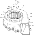
- the centrifugal blower 10 shown in FIG. 1 is applied to a blower unit that blows air to an indoor unit of a vehicle air conditioner, for example.
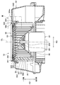
- the centrifugal blower 10 includes an electric motor 20 having a rotating shaft 200, an impeller 30 that is rotationally driven by the electric motor 20 and blows out air, and a casing 50 that houses the impeller 30.
- . 2 indicates the axial direction extending along the axis CL of the rotation shaft 200. 2 indicates the radial direction orthogonal to the axial direction AD of the rotating shaft 200.
- the impeller 30 is a member that rotates about the axis CL of the rotation shaft 200.
- the impeller 30 includes a plurality of blades 32 that are arranged radially with respect to the rotation shaft 200, an annular shroud 34 that connects one end of each blade 32 in the axial direction AD, and a shaft in each blade 32. It has a main plate 36 that connects the other ends of the direction AD.
- the plurality of blades 32, the shroud 34, and the main plate 36 constituting the impeller 30 of the present embodiment are configured as an integrally molded product.
- each of the plurality of blades 32, the shroud 34, and the main plate 36 is made of resin and integrally formed by injection molding.
- the impeller 30 is composed of a sirocco fan in which each blade 32 faces the front side in the rotation direction. Among each blade 32, an air flow path through which air flows is formed between adjacent blades 32. Each blade 32 has a front edge portion 321 constituting an air inflow portion and a rear edge portion 322 constituting an air outflow portion.
- the shroud 34 of the impeller 30 is composed of an annular plate member having an open central portion.
- the shroud 34 is connected to a portion on one side in the axial direction AD of each blade 32.
- the shroud 34 has a shroud side upper end portion 341 that constitutes an end portion on the upstream side of the air flow, and a shroud side lower end portion 342 that constitutes an end portion on the downstream side of the air flow. is doing.
- the shroud 34 includes a shroud-side inner surface portion 343 that forms the inner surface of the rotating shaft 200 in the radial direction RD, and a shroud-side outer surface portion 344 that forms the outer surface of the rotating shaft 200 in the radial direction RD.
- the shroud side inner surface portion 343 forms an inlet for introducing air sucked from an air suction portion 56 of the casing 50 described later into the inside of the impeller 30.
- the shroud-side inner surface portion 343 has a shape that swells toward the inside of the impeller 30 so that air that flows in from the axial direction AD of the rotating shaft 200 is guided to the outside of the radial direction RD of the rotating shaft 200. .
- the diameter of the shroud side inner surface portion 343 gradually increases from the shroud side upper end portion 341 toward the shroud side lower end portion 342.
- a portion on the shroud side upper end portion 341 side has a minimum diameter Ds.
- the shroud 34 has a thickness Ts at a portion close to the shroud side upper end 341, that is, a portion where the minimum diameter Ds is set, for example, about 1 to 3 mm. Yes.
- the main plate 36 of the impeller 30 is provided with a cylindrical connecting portion 361 provided in the center portion, and the rotary shaft 200 is connected via the connecting portion 361.
- the main plate 36 is connected to a portion of each blade 32 facing the shroud 34 in the axial direction AD of the rotary shaft 200 on the other side of the blade 32 in the axial direction AD of the rotary shaft 200.
- the main plate 36 is a cone whose central portion protrudes to one side of the axial direction AD so that air flowing in from the axial direction AD of the rotating shaft 200 is guided to the outside of the radial direction RD of the rotating shaft 200. It has a shape.
- the main plate 36 may have a flat shape extending along the radial direction RD of the rotating shaft 200.
- the casing 50 includes a scroll part 52 that houses the impeller 30, a blower part 54 that connects the scroll part 52 to an indoor unit (not shown), and an air suction part 56.
- the scroll part 52 is a member that forms a spiral air flow path outside the impeller 30.
- the scroll portion 52 gradually increases in diameter along the rotation direction of the impeller 30.
- the scroll part 52 has a winding start part 52 a having the smallest diameter in the rotation direction of the impeller 30 and a winding end part 52 b having the largest diameter in the rotation direction of the impeller 30.
- the air blowing part 54 is connected between the winding start part 52a and the winding end part 52b in the scroll part 52.
- the air blowing part 54 extends along a tangent to the winding end part 52 b of the scroll part 52.
- an air discharge part 54a is opened on the downstream side of the air flow of the air blowing part 54.
- the scroll portion 52 is provided with an annular cylindrical portion 522 for attaching the air suction portion 56 to a portion on the one side in the axial direction AD of the rotating shaft 200 and close to the shroud 34 of the impeller 30. ing.
- the cylindrical portion 522 protrudes toward one side in the axial direction AD of the rotating shaft 200. A part of the cylindrical portion 522 is opposed to the shroud side outer surface portion 344 in the axial direction AD of the rotating shaft 200.
- the air suction portion 56 is an annular member that guides air to the inside of the impeller 30.
- the air suction part 56 is configured in a bell mouth shape.
- the air suction part 56 is joined to the cylindrical part 522 of the scroll part 52 by a joining technique such as an adhesive or welding.
- the air suction portion 56 may be connected to the cylindrical portion 522 of the scroll portion 52 by a connecting element such as a screw.
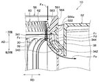
- the air suction portion 56 has a bell mouth side upper end portion 561 that constitutes an end portion on the upstream side of the air flow, and a bell mouth side lower end portion 562 that constitutes an end portion on the downstream side of the air flow. ing.
- the air suction portion 56 includes a bell mouth side inner surface portion 563 that constitutes the inner surface of the rotating shaft 200 in the radial direction RD, and a bell mouth side outer surface portion 564 that constitutes the outer surface of the rotating shaft 200 in the radial direction RD. have.
- the air suction portion 56 is a scroll portion so that the bell mouth side lower end portion 562 and the shroud side upper end portion 341 are spaced from each other in the axial direction AD of the rotating shaft 200 so as to face the axial direction AD of the rotating shaft 200. 52 is provided.
- the air suction portion 56 is provided in a portion of the scroll portion 52 that does not overlap the shroud 34 in the radial direction RD of the rotation shaft 200.
- the bell mouth side inner surface portion 563 forms an inlet for sucking air into the inside of the impeller 30.
- the bell mouth side inner surface portion 563 has a shape bulging inward in order to guide air to the inside of the impeller 30.
- the diameter of the bell mouth side inner surface portion 563 gradually decreases from the bell mouth side upper end portion 561 toward the bell mouth side lower end portion 562.
- a portion on the bell mouth side lower end portion 562 side has a minimum diameter Db.
- the bell mouth side outer surface portion 564 extends along the axial direction AD of the rotating shaft 200.
- the bell mouth side outer surface portion 564 is formed with a fitting groove portion 564 a that fits with the cylindrical portion 522 of the scroll portion 52.
- the bell mouth side inner surface portion 563 and the shroud side inner surface portion 343 of the present embodiment have a shape having substantially no step between the bell mouth side inner surface portion 563 and the shroud side inner surface portion 343.
- the difference between the minimum diameter Db on the bell mouth side inner surface portion 563 side and the minimum diameter Ds on the shroud side inner surface portion 343 side is equal to or less than the thickness Ts of the shroud 34. (That is,
- the inner surface portions 563 and 343 of the present embodiment are set such that the minimum diameter Db on the bell mouth side inner surface portion 563 side is equal to or smaller than the minimum diameter Ds on the shroud side inner surface portion 343 side (that is, Db ⁇ Ds).
- the inner surface portions 563 and 343 of the present embodiment are set so that the minimum diameter Db on the bell mouth side inner surface portion 563 side and the minimum diameter Ds on the shroud side inner surface portion 343 side substantially match. (Ie, Db ⁇ Ds).
- both the bell mouth side lower end portion 562 side of the bell mouth side inner surface portion 563 and the shroud side upper end portion 341 side of the shroud side inner surface portion 343 are in the axial direction AD of the rotary shaft 200. Extending in parallel.
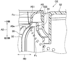
- the impeller 30 has a clearance channel 38 formed between the cylindrical portion 522 of the scroll portion 52 and the bell mouth side lower end portion 562 and the shroud side outer surface portion 344 on the air suction side and the air discharge side. It communicates through. Therefore, a part of the air discharged from the impeller 30 indicated by the arrow Fo in FIG. 3 flows backward to the air suction side of the impeller 30 through the gap channel 38 as indicated by the arrow Fr in FIG. Sometimes.
- This reverse flow flows in a direction in which the airflow along the bell mouth side inner surface portion 563 is separated from the shroud side inner surface portion 343. That is, the backflow is a factor that inhibits the airflow along the bell mouth side inner surface portion 563 from flowing along the shroud side inner surface portion 343.
- a vertical vortex generating mechanism 60 is installed in the air suction portion 56 of the present embodiment with respect to the bell mouth side inner surface portion 563.
- the vertical vortex generating mechanism 60 is a mechanism that generates a spiral vertical vortex having a central axis of rotation in a direction along the main flow of air flowing into the air suction portion 56.
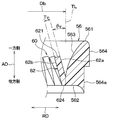
- the vertical vortex generating mechanism 60 has a plurality of triangular teeth 62 whose width in the circumferential direction of the rotating shaft 200 is reduced toward the tip side.
- the plurality of tooth portions 62 constituting the vertical vortex generating mechanism 60 are installed over the entire circumference of the bell mouth side inner surface portion 563.
- Each tooth portion 62 constituting the vertical vortex generating mechanism 60 has a tooth tip portion 621 connecting two intersecting sides 622 and 623 located on the upstream side of the air flow from the root portion 624 in contact with the bell mouth side inner surface portion 563. Is installed. Specifically, each tooth portion 62 has a shape that is sharpened toward the tooth tip portion 621. Each tooth portion 62 protrudes toward the upstream side of the air flow.
- the tooth tip 621 of each tooth portion 62 is not limited to the sharp shape in which the two sides 622 and 623 extending in a straight line intersect, but may have a shape in which C chamfering or R chamfering is performed.
- each tooth portion 62 is formed on the bell mouth side inner surface portion 563 in an inclined state so that the tooth tip portion 621 is positioned inside the radial direction RD of the rotation shaft 200 with respect to the root portion 624. is set up. Specifically, each tooth portion 62 is installed such that the distance from the tangent line TL at the portion having the minimum diameter Db of the bell mouth side inner surface portion 563 increases toward the tooth tip portion 621. Note that the tangent line TL is a direction in which a portion having the minimum diameter Db of the bell mouth side inner surface portion 563 extends.
- Each tooth portion 62 is bellmouth in a state where the skew angle ⁇ v formed by the direction extending from the root portion 624 toward the tooth tip portion 621 and the tangent line TL of the bellmouth side inner surface portion 563 is an acute angle. It is installed on the side inner surface portion 563. Specifically, each tooth portion 62 of the present embodiment is installed on the bell mouth side inner surface portion 563 in an inclined state so that the skew angle ⁇ v is approximately 30 °.
- each tooth portion 62 of the present embodiment is formed in an isosceles triangle shape in which the lengths of two sides 622 and 623 intersecting at the tooth tip portion 621 are equal.
- each tooth portion 62 of the present embodiment has a width dimension Wv of the root portion 624 where the distance between the two sides 622 and 623 is maximum, and the length between the root portion 624 and the tooth tip portion 621 is minimum. It is smaller than the height dimension Hv at the position.
- the width dimension Wv and the height dimension Hv are dimensions on the negative pressure surface 62b side of each tooth portion 62.
- Each tooth portion 62 of the present embodiment has a shape in which the aspect ratio AR is “2.0” when the ratio of the height dimension Hv to the width dimension Wv is the aspect ratio AR. That is, each tooth portion 62 of the present embodiment has a shape in which the height dimension Hv is approximately twice the width dimension Wv.
- the two sides 622 and 623 of the respective tooth portions 62 on the positive pressure surface 62a side are shorter than the suction surface 62b side. If the lengths of the two sides 622 and 623 on the positive pressure surface 62a side of each tooth portion 62 are shortened, the two sides 622 and 623 of each tooth portion 62 may have an adverse effect on the occurrence of vertical vortices appropriately. There is.
- the plate thickness Tv of each tooth portion 62 is equal to or less than the thickness Ts of the shroud 34 (that is, Tv ⁇ Ts).
- the positive pressure surface 62a in each tooth part 62 is an opposing surface which opposes the bellmouth side inner surface part 563.
- the negative pressure surface 62b in each tooth part 62 is a back surface of the positive pressure surface 62a.
- the air suction part 56 and the vertical vortex generating mechanism 60 of the present embodiment configured as described above are configured as an integrally molded product.
- the air suction portion 56 and the vertical vortex generating mechanism 60 are made of resin and are integrally formed by injection molding.
- each tooth portion 62 of the present embodiment has a minimum diameter in the bell mouth side inner surface portion 563 so that the tooth tip portion 621 side and the bell mouth side inner surface portion 563 do not overlap in the axial direction AD of the rotation shaft 200. It is installed in the part which becomes Db.
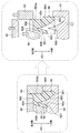
- the air suction portion 56 and the vertical vortex generating mechanism 60 can be integrally molded by injection molding using the first to fourth molding dies 91 to 94. it can.
- the first molding die 91 is disposed on one side in the axial direction AD of the rotary shaft 200 and is exposed to one side in the axial direction AD of the rotary shaft 200 in the air suction portion 56 and the vertical vortex generating mechanism 60. It has a shape corresponding to.
- the second molding die 92 is disposed on the other side in the axial direction AD of the rotating shaft 200 and has a shape corresponding to the bell mouth side lower end portion 562 of the air suction portion 56.
- the third molding die 93 is disposed on the other side in the axial direction AD of the rotating shaft 200 and has a shape corresponding to the bell mouth side outer surface portion 564 of the air suction portion 56. Further, the fourth molding die 94 is disposed between the first molding die 91 and the second molding die 92, and is disposed on the other side in the axial direction AD of the rotary shaft 200 in the vertical vortex generating mechanism 60. It has a shape corresponding to the exposed part.
- the air suction portion 56 and the vertical vortex generating mechanism 60 of the present embodiment are configured such that the bell mouth side inner surface portion 563 and the tooth tip portion 621 side of each tooth portion 62 do not overlap in the axial direction AD of the rotating shaft 200. ing. Therefore, as shown on the right side of FIG. 7, the vertical vortex generating mechanism 60 and the air suction unit 56 are integrated with each other by a molding process in which the axial direction AD of the rotary shaft 200 is the die cutting direction without performing an undercut process. It can be molded. This has an advantage that an increase in manufacturing cost of the centrifugal blower 10 due to the addition of the vertical vortex generating mechanism 60 can be suppressed.
- the centrifugal blower 10 of this embodiment will be described.
- the impeller 30 rotates with the rotation of the rotating shaft 200 of the electric motor 20.
- the air sucked into the impeller 30 from the air suction part 56 is blown out toward the outside of the radial direction RD of the rotating shaft 200 by the centrifugal force.
- FIG. 8 is a drawing showing the airflow in the vicinity of the shroud 34 of the centrifugal blower CE as a comparative example of the present embodiment.
- the centrifugal blower CE of the comparative example is that the shroud 34 is located on the outer surface side of the air suction part AS and that the vertical vortex generating mechanism 60 is not provided in the air suction part AS. Is different.
- the same reference numerals are assigned to the same configurations as the centrifugal blower 10 of the present embodiment in the centrifugal blower CE of the comparative example.
- the airflow along the inner surface ASi of the air suction part AS is sucked into the impeller 30 by the rotation of the impeller 30.
- the air flow along the inner surface ASi of the air suction part AS is the lower end of the air suction part AS on the downstream side of the air flow. Peel off at part ASe.
- the airflow flowing from the inner surface ASi of the air suction portion AS to the vicinity of the shroud 34 of the impeller 30 causes a disturbance accompanied by a lateral vortex.
- the turbulence of the airflow grows as it proceeds to the downstream side of the air flow in the impeller 30.
- the horizontal vortex is a vortex having a central axis of rotation that intersects with the flow direction of the main flow of air.
- the difference between the minimum diameter Db of the bell mouth side inner surface portion 563 of the air suction portion 56 and the minimum diameter Ds of the shroud side inner surface portion 343 is equal to or less than the thickness Ts of the shroud 34. Is set to
- the airflow along the bell mouth side inner surface portion 563 of the air suction portion 56 easily reattaches to the shroud side inner surface portion 343 after leaving the bell mouth side lower end portion 562. That is, in the centrifugal blower 10 according to the present embodiment, the airflow in the vicinity of the shroud side inner surface portion 343 can easily flow along the shroud side inner surface portion 343.
- a part of the air discharged from the impeller 30 indicated by the arrow Fo in FIG. 3 is part of the air of the impeller 30 through the gap channel 38 as indicated by the arrow Fr in FIG. 3. May flow backward to inhalation side. This reverse flow flows in a direction in which the airflow along the bell mouth side inner surface portion 563 is separated from the shroud side inner surface portion 343.
- the vertical vortex generating mechanism 60 is installed on the bell mouth side inner surface portion 563.
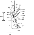
- the airflow along the bell mouth side inner surface portion 563 gets over the two sides 622 and 623 of each tooth portion 62 of the vertical vortex generating mechanism 60, the arrows in FIGS. As indicated by Fv, a vertical vortex is generated.
- the kinetic energy of the airflow away from the bellmouth side inner surface portion 563 is added to the airflow close to the bellmouth side inner surface portion 563 by the vertical vortex.
- the airflow from the bell mouth side inner surface portion 563 toward the shroud side inner surface portion 343 is pressed toward the shroud side inner surface portion 343 as indicated by an arrow Fd in FIG.
- the arrow Fd of FIG. 10 has shown the direction of the downflow which exhibits the pressing force which presses an airflow against the shroud side inner surface part 343.
- centrifugal blower 10 of the present embodiment described above has a shape having substantially no step between the bell mouth side inner surface portion 563 and the shroud side inner surface portion 343, the air flow along the bell mouth side inner surface portion 563. Becomes easy to flow along the shroud side inner surface portion 343.
- the bell mouth side inner surface portion 563 is provided with a vertical vortex generating mechanism 60 for generating a vertical vortex. According to this, even if a back flow occurs in the gap flow path 38, the airflow from the bell mouth side inner surface portion 563 toward the shroud side inner surface portion 343 easily flows along the shroud 34 without being separated from the vicinity of the shroud 34. Become.
- the airflow along the air suction portion 56 easily flows smoothly to the shroud 34 side, so that separation of the airflow on the shroud 34 side of the blades 32 can be sufficiently suppressed. .
- the centrifugal blower 10 of the present embodiment includes a plurality of teeth 62 in which the longitudinal vortex generating mechanism 60 is formed in a triangular shape. According to this, when the airflow along the bell mouth side inner surface portion 563 flows across the plurality of tooth portions 62, vertical vortices are generated at the two sides 622 and 623 of each tooth portion 62. Thereby, the kinetic energy of the airflow away from the bellmouth side inner surface portion 563 is added to the airflow close to the bellmouth side inner surface portion 563, so that the airflow from the bellmouth side inner surface portion 563 toward the shroud side inner surface portion 343 is generated. , And pressed against the shroud side inner surface portion 343 side.
- the centrifugal blower 10 of the present embodiment is set such that the minimum diameter Db on the bell mouth side inner surface portion 563 side is equal to or smaller than the minimum diameter Ds on the shroud side inner surface portion 343 side (that is, Db ⁇ Ds). According to this, it is possible to prevent the airflow along the bell mouth side inner surface portion 563 from being disturbed by the collision with the shroud 34.
- FIG. 12 is a characteristic diagram showing changes in the downflow velocity Vdf when the aspect ratio ARv of each tooth portion 62 of the vertical vortex generating mechanism 60 is changed.
- FIG. 12 shows the results when each tooth portion 62 is modeled as a 3D model and the downflow velocity Vdf on the downstream side of each tooth portion 62 is digitized by CFD analysis.
- the downflow speed Vdf is the speed of the downflow Fd.
- the downflow speed Vdf becomes significantly larger when the aspect ratio ARv is near “2.0” than when the aspect ratio ARv is “1.0” or “3.0”. I found out. Such a tendency was the same when the skew angle ⁇ v was changed.
- each tooth portion 62 has a shape in which the aspect ratio ARv is larger than 1.0 and smaller than 3.0 (that is, 1.0 ⁇ ARv ⁇ 3.0). In particular, it is desirable that each tooth portion 62 has a shape with an aspect ratio ARv of approximately 2.0.
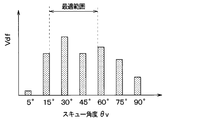
- FIG. 13 is a characteristic diagram showing changes in the downflow velocity Vdf when the skew angle ⁇ v of each tooth portion 62 of the vertical vortex generating mechanism 60 is changed.
- FIG. 13 shows a result when each tooth portion 62 is modeled in 3D and the downflow velocity Vdf on the downstream side of each tooth portion 62 is quantified by CFD analysis.
- each tooth portion 62 is installed on the bell mouth side inner surface portion 563 so that the skew angle ⁇ v is in a range larger than 15 ° and smaller than 60 ° (that is, 15 ° ⁇ v ⁇ 60 °). Is desirable.
- each tooth portion 62 is desirably installed on the bell mouth side inner surface portion 563 so that the skew angle ⁇ v is approximately 30 °.
- the example in which the plurality of tooth portions 62 configuring the vertical vortex generating mechanism 60 are installed over the entire circumference of the bell mouth side inner surface portion 563 is not limited thereto.
- the centrifugal blower 10 may have a configuration in which a plurality of tooth portions 62 constituting the vertical vortex generating mechanism 60 are installed in a part of the bell mouth side inner surface portion 563.
- the vertical vortex generating mechanism 60 is provided at least at a site where the winding start portion 52a and the winding end portion 52b in the scroll portion 52 communicate with each other.
- each tooth portion 62 preferably has a shape in which the aspect ratio ARv is larger than 1.0 and smaller than 3.0, but is not limited thereto.
- Each tooth portion 62 may have a shape in which at least a part of the aspect ratio ARv is 1.0 or less, or 3.0 or more.
- each tooth portion 62 is desirably installed on the bell mouth side inner surface portion 563 so that the skew angle ⁇ v is in a range larger than 15 ° and smaller than 60 °. It is not limited. Each tooth portion 62 may be installed on the bell mouth side inner surface portion 563 so that at least a part of the skew angle ⁇ v is 15 ° or less or 60 ° or more.
- the plate thickness Tv of each tooth portion 62 be equal to or less than the thickness Ts of the shroud 34, but the present invention is not limited to this.
- the plate thickness Tv of each tooth portion 62 may be set to a lower limit value in a range in which the strength of each tooth portion 62 can be secured, for example.
- the air suction portion 56 and the vertical vortex generating mechanism 60 may be configured such that, for example, each member configured separately is joined by an adhesive or the like.
- the vertical vortex generating mechanism 60 is configured by a plurality of triangular tooth portions 62
- the present invention is not limited to this.
- the vertical vortex generating mechanism 60 may be configured by a plurality of triangular pyramid-shaped convex portions, for example.
- centrifugal blower 10 of the present disclosure is applied to a blower unit of a vehicle air conditioner, but the present invention is not limited to this.
- the centrifugal blower 10 of the present disclosure can be widely applied to other apparatuses such as a stationary type air conditioner.
- the impeller 30 is configured by a sirocco fan in which each blade 32 faces forward is described, but the present invention is not limited to this.
- the impeller 30 may be configured by, for example, a turbofan in which each blade 32 faces backward.
- the casing 50 having the scroll part 52 is illustrated, but the present invention is not limited to this.
- an all-round blow-out type casing 50 that does not have the scroll part 52 may be employed.
- the centrifugal air blower becomes a shape which does not have a level
- a vertical vortex generating mechanism for generating a vertical vortex is provided on the inner surface of the bell mouth side.
- the centrifugal blower is configured such that the vertical vortex generating mechanism includes a plurality of tooth portions formed in a triangular shape.
- the tooth portion is located on the upstream side of the air flow with respect to the root portion that contacts the bellmouth side inner surface portion, and the tooth tip portion is located on the radially inner side with respect to the root portion. It is installed on the inner surface of the bell mouth side so as to be inclined.
- the centrifugal blower has a tooth portion having an aspect ratio larger than 1.0 and smaller than 3.0.
- the width dimension is an interval at a position where the interval between the two sides of the tooth portion is maximum.
- the height dimension is a length at a position where the length of the root portion and the tooth tip portion is minimum.
- the aspect ratio is the ratio of the height dimension to the width dimension.
- gear part is installed in the bell mouth side inner surface part so that a skew angle may become the range which is larger than 15 degrees and smaller than 60 degrees.
- a skew angle may become the range which is larger than 15 degrees and smaller than 60 degrees.
- the centrifugal blower has a tooth thickness equal to or less than the thickness of the shroud.
- the centrifugal blower is configured such that the vertical vortex generating mechanism and the air suction portion are integrally formed. And the several tooth
- the axial direction of the rotating shaft is set as the die cutting direction without performing an undercut process.
- the vertical vortex generating mechanism and the air suction part can be molded integrally. As a result, it is possible to suppress an increase in the manufacturing cost of the centrifugal blower accompanying the addition of the vertical vortex generating mechanism.
- the diameter of the portion that becomes the minimum diameter in the bell mouth side inner surface portion is set to be equal to or smaller than the diameter of the portion that becomes the minimum diameter in the shroud side inner surface portion. According to this, it can suppress that the airflow which follows the bell mouth side inner surface part will be disturb
Abstract
遠心送風機は、羽根車(30)と、空気吸入部(56)が形成されたケーシング(50)と、を備える。空気吸入部は、空気流れ下流側の端部を構成するベルマウス側下端部(562)、および径方向の内側の表面を構成するベルマウス側内面部(563)を有している。シュラウドは、空気流れ上流側の端部を構成するシュラウド側上端部(341)、および径方向の内側の表面を構成するシュラウド側内面部(343)を有している。空気吸入部およびシュラウドは、ベルマウス側下端部とシュラウド側上端部とが軸方向に隔間をあけた状態で軸方向に対向配置されている。また、ベルマウス側内面部における最小径となる部位の径(Db)とシュラウド側内面部における最小径となる部位の径(Ds)との差がシュラウドの厚み(Ts)以下に設定されている。そして、ベルマウス側内面部には、縦渦を発生させる縦渦発生機構(60)が設けられている。
Description
本出願は、2017年3月13日に出願された日本出願番号2017-47478号に基づくものであって、ここにその記載内容を援用する。
本開示は、回転軸の軸方向の一方側から吸い込んだ空気を回転軸の径方向の外側に向けて吹き出す遠心送風機に関する。
従来、遠心ファンにおけるシュラウドとベルマウスとの隙間からの漏れ流れを低減して、主流との干渉による羽根の負圧面側の剥離騒音を下げる遠心送風機が提案されている(例えば、特許文献1参照)。この特許文献1には、シュラウドの羽根の負圧面領域における空気吸込側端部のベルマウスに対向する部位に、回転方向に沿うラビリンスシール部を設けた構成が開示されている。
ところで、特許文献1に開示された遠心送風機は、ベルマウスの外面側にシュラウドが位置しており、ベルマウスとシュラウドとの間に段差が形成される。このため、ベルマウスの内面に沿う気流が、ベルマウスの空気流れ下流側の端部で剥離してシュラウドの内面に沿った流れにならない。すなわち、ベルマウスとシュラウドとの間に段差が形成される遠心送風機では、ベルマウスの内面から羽根車のシュラウド付近に流入する気流に乱れが生ずる。このような気流の乱れは、羽根車の空気流れ下流側に進むにつれて成長するので、騒音増加や送風効率の低下を招く要因となる。
そこで、本発明者らは、ベルマウスとシュラウドとの間に段差が形成されない構成について検討した。具体的には、本発明者らは、ベルマウスの空気流れ下流側の端部とシュラウドの空気流れ上流側の端部とを回転軸の軸方向に対向させると共に、ベルマウスの内面側の内径と、シュラウドの内面側の内径とを同等の大きさにすることを検討した。
しかしながら、本発明者らの検討によれば、上述の構成では、羽根のシュラウド側における剥離抑制効果を充分に得ることができないことが判った。理由としては、羽根のシュラウド側を流れる気流が、ベルマウスとシュラウドとの隙間から羽根車の内側に向かう逆流の影響によって乱れてしまうことが挙げられる。
本開示は、羽根のシュラウド側における剥離抑制効果を充分に得ることが可能な遠心送風機を提供することを目的とする。
本開示は、回転軸の軸方向の一方側から吸い込んだ空気を回転軸の径方向の外側に向けて吐出する遠心送風機を対象としている。
本開示の1つの観点によれば、遠心送風機は、
回転軸の軸線に対して放射状に配置された複数枚の羽根、および複数枚の羽根における軸方向の一方側の端部同士を連結する環状のシュラウドを有し、回転軸の軸線を中心として回転する羽根車と、
羽根車を収容すると共に、シュラウドに近接する部位に羽根車の内側に空気を導くベルマウス状の空気吸入部が形成されたケーシングと、を備える。
回転軸の軸線に対して放射状に配置された複数枚の羽根、および複数枚の羽根における軸方向の一方側の端部同士を連結する環状のシュラウドを有し、回転軸の軸線を中心として回転する羽根車と、
羽根車を収容すると共に、シュラウドに近接する部位に羽根車の内側に空気を導くベルマウス状の空気吸入部が形成されたケーシングと、を備える。
空気吸入部は、空気流れ下流側の端部を構成するベルマウス側下端部、および径方向の内側の表面を構成するベルマウス側内面部を有している。シュラウドは、空気流れ上流側の端部を構成するシュラウド側上端部、および径方向の内側の表面を構成するシュラウド側内面部を有している。
空気吸入部およびシュラウドは、ベルマウス側下端部とシュラウド側上端部とが軸方向に隔間をあけた状態で軸方向に対向配置されている。さらに、空気吸入部およびシュラウドは、ベルマウス側内面部における最小径となる部位の径とシュラウド側内面部における最小径となる部位の径との差がシュラウドの厚み以下に設定されている。そして、ベルマウス側内面部には、空気の主流に沿う方向に回転の中心軸を持つ縦渦を発生させる縦渦発生機構が設けられている。
これによると、ベルマウス側内面部とシュラウド側内面部との間に実質的に段差がない形状となるので、ベルマウス側内面部に沿う気流がシュラウド側内面部に沿って流れ易くなる。
加えて、ベルマウス側内面部には、縦渦を発生させる縦渦発生機構が設けられている。これによると、仮に、ベルマウス側下端部とシュラウド側上端部との隙間から羽根車の内側に向かう逆流が生じたとしても、ベルマウス側内面部からシュラウド側内面部に向かう気流が、縦渦発生機構で生じた縦渦によってシュラウド側内面部側に押し付けられる。
従って、本開示の遠心送風機によれば、空気吸入部に沿う気流がシュラウド側へ滑らかに流れ易くなるので、羽根のシュラウド側における気流の剥離を充分に抑制することができる。この結果、羽根車のシュラウド付近における気流の乱れに起因する騒音を低減し、送風効率の向上を図ることが可能な遠心送風機を実現することができる。なお、ベルマウス状の空気吸入部とは、径方向の内側の表面が上流側に向かってラッパ状に滑らかに拡大した形状を有する空気吸入部を意味する。
本開示の一実施形態について図1~図13を参照して説明する。図1に示す遠心送風機10は、例えば、車両用空調装置の室内ユニットに空気を送風する送風ユニットに適用される。
図2に示すように、遠心送風機10は、回転軸200を有する電動モータ20と、電動モータ20によって回転駆動されて空気を吹き出す羽根車30と、羽根車30を収容するケーシング50と、を備える。なお、図2に示す矢印ADは、回転軸200の軸線CLに沿って延びる軸方向を示している。また、図2に示す矢印RDは、回転軸200の軸方向ADに直交する径方向を示している。
羽根車30は、回転軸200の軸線CLを中心として回転する部材である。羽根車30は、回転軸200に対して放射状に配置された複数枚の羽根32、各羽根32における軸方向ADの一方側の端部同士を連結する環状のシュラウド34、および各羽根32における軸方向ADの他方側の端部同士を連結する主板36を有する。
本実施形態の羽根車30を構成する複数の羽根32、シュラウド34、および主板36は、一体成形物として構成されている。具体的には、複数の羽根32、シュラウド34、および主板36それぞれは、樹脂で構成されると共に、射出成形によって一体成形されている。
羽根車30は、各羽根32が回転方向の前方側を向いたシロッコファンで構成されている。各羽根32のうち、隣り合う羽根32の間には、空気が流通する空気流路が形成されている。各羽根32は、空気の流入部を構成する前縁部321、空気の流出部を構成する後縁部322を有する。
続いて、羽根車30のシュラウド34は、中央部分が開口する円環状の板部材で構成されている。シュラウド34は、各羽根32それぞれの軸方向ADの一方側の部位に連結されている。
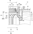
具体的には、図3に示すように、シュラウド34は、空気流れ上流側の端部を構成するシュラウド側上端部341、および空気流れ下流側の端部を構成するシュラウド側下端部342を有している。
また、シュラウド34は、回転軸200の径方向RDの内側の表面を構成するシュラウド側内面部343、および回転軸200の径方向RDの外側の表面を構成するシュラウド側外面部344を有している。
シュラウド側内面部343は、後述するケーシング50の空気吸入部56から吸い込まれた空気を羽根車30の内側に導入する導入口を形成している。シュラウド側内面部343は、回転軸200の軸方向ADから流入した空気が、回転軸200の径方向RDの外側に導かれるように、羽根車30の内側に向けて膨らんだ形状となっている。
具体的には、シュラウド側内面部343は、シュラウド側上端部341からシュラウド側下端部342に向かって、その径が徐々に大きくなっている。本実施形態のシュラウド側内面部343は、シュラウド側上端部341側の部位が最小径Dsとなっている。
また、シュラウド34は、羽根車30の軽量化を図るために、シュラウド側上端部341に近接する部位、すなわち、最小径Dsとなる部位における厚みTsが、例えば、1~3mm程度に設定されている。
図2に戻り、羽根車30の主板36は、中央部分に設けられた筒状の連結部361が設けられ、当該連結部361を介して回転軸200が連結されている。また、主板36には、回転軸200の軸方向ADにおいてシュラウド34に対向する部位に、各羽根32における回転軸200の軸方向ADの他方側の部位が連結されている。
具体的には、主板36は、回転軸200の軸方向ADから流入した空気が回転軸200の径方向RDの外側に導かれるように、その中央部分が軸方向ADの一方側に突き出た円錐状の形状となっている。なお、主板36は、回転軸200の径方向RDに沿って延びる平坦な形状となっていてもよい。
このように構成される羽根車30は、ケーシング50の内部に収容されている。図1に示すように、ケーシング50は、羽根車30を収容するスクロール部52、スクロール部52を図示しない室内ユニットに接続する送風部54、および空気吸入部56を有している。
スクロール部52は、羽根車30の外側に渦巻き状の空気流路を形成する部材である。スクロール部52は、羽根車30の回転方向に沿って徐々に径が大きくなっている。スクロール部52は、羽根車30の回転方向において最も小径となる巻き始め部52a、および羽根車30の回転方向において最も大径となる巻き終り部52bを有している。
送風部54は、スクロール部52における巻き始め部52aと巻き終わり部52bとの間に接続されている。送風部54は、スクロール部52の巻き終わり部52bの接線に沿って延びている。送風部54の空気流れ下流側には、空気の吐出部54aが開口している。
スクロール部52には、回転軸200の軸方向ADの一方側であって、羽根車30のシュラウド34に近接する部位に、空気吸入部56を取り付けるための円環状の筒状部522が設けられている。この筒状部522は、回転軸200の軸方向ADの一方側に向けて突出している。筒状部522は、その一部が、回転軸200の軸方向ADにおいて、シュラウド側外面部344に対して対向している。
空気吸入部56は、羽根車30の内側に空気を導く円環状の部材である。空気吸入部56は、ベルマウス状に構成されている。空気吸入部56は、スクロール部52の筒状部522に対して接着剤や、溶着等の接合技術によって接合されている。なお、空気吸入部56は、スクロール部52の筒状部522に対して、ビス等の連結要素によって連結されていてもよい。
図3に示すように、空気吸入部56は、空気流れ上流側の端部を構成するベルマウス側上端部561、および空気流れ下流側の端部を構成するベルマウス側下端部562を有している。
また、空気吸入部56は、回転軸200の径方向RDの内側の表面を構成するベルマウス側内面部563、および回転軸200の径方向RDの外側の表面を構成するベルマウス側外面部564を有している。
空気吸入部56は、ベルマウス側下端部562とシュラウド側上端部341とが回転軸200の軸方向ADに隔間をあけた状態で、回転軸200の軸方向ADに対向するようにスクロール部52に設けられている。そして、空気吸入部56は、スクロール部52のうち、回転軸200の径方向RDにおいて、シュラウド34と重なり合わない部位に設けられている。
ベルマウス側内面部563は、空気を羽根車30の内側に吸入する吸入口を形成している。ベルマウス側内面部563は、羽根車30の内側に空気を導くために、内側に向けて膨らんだ形状を有している。
具体的には、ベルマウス側内面部563は、ベルマウス側上端部561からベルマウス側下端部562に向かって、その径が徐々に小さくなっている。本実施形態のベルマウス側内面部563は、ベルマウス側下端部562側の部位が最小径Dbとなっている。
ベルマウス側外面部564は、回転軸200の軸方向ADに沿って延びている。ベルマウス側外面部564には、スクロール部52の筒状部522と嵌合する嵌合溝部564aが形成されている。
ここで、ベルマウス側内面部563とシュラウド側内面部343との間に段差が形成されていると、ベルマウス側内面部563に沿う気流が、ベルマウス側下端部562で剥離して、シュラウド側内面部343に沿った流れとならない。
これに対して、本実施形態のベルマウス側内面部563およびシュラウド側内面部343は、ベルマウス側内面部563とシュラウド側内面部343との間に実質に段差がない形状となっている。つまり、本実施形態の各内面部563、343は、ベルマウス側内面部563側の最小径Dbとシュラウド側内面部343側の最小径Dsとの差が、シュラウド34の厚みTs以下となるように設定されている(すなわち、|Ds-Db|≦Ts)。
特に、本実施形態の各内面部563、343は、ベルマウス側内面部563側の最小径Dbがシュラウド側内面部343側の最小径Ds以下となるように設定されている(すなわち、Db≦Ds)。具体的には、本実施形態の各内面部563、343は、ベルマウス側内面部563側の最小径Dbとシュラウド側内面部343側の最小径Dsとが実質的に一致するように設定されている(すなわち、Db≒Ds)。
また、本実施形態の遠心送風機10は、ベルマウス側内面部563のベルマウス側下端部562側、およびシュラウド側内面部343のシュラウド側上端部341側の双方が、回転軸200の軸方向ADに並行に延びている。
ここで、羽根車30は、空気吸入側と空気吐出側とが、スクロール部52の筒状部522およびベルマウス側下端部562とシュラウド側外面部344との間に形成される隙間流路38を介して連通している。このため、図3の矢印Foに示す羽根車30から吐出された空気の一部が、図3の矢印Frに示すように、隙間流路38を介して羽根車30の空気吸入側に逆流することがある。この逆流は、ベルマウス側内面部563に沿う気流をシュラウド側内面部343から離間させる向きに流れる。すなわち、逆流は、ベルマウス側内面部563に沿う気流がシュラウド側内面部343に沿って流れることを阻害する要因となる。
そこで、本実施形態の空気吸入部56には、ベルマウス側内面部563に対して、縦渦発生機構60が設置されている。縦渦発生機構60は、空気吸入部56に流入する空気の主流に沿う方向に回転の中心軸を持つ螺旋状の縦渦を発生させる機構である。
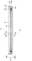
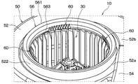
図4に示すように、縦渦発生機構60は、回転軸200の周方向における幅が先端側に向かって縮小された三角形状の複数の歯部62を有している。縦渦発生機構60を構成する複数の歯部62は、ベルマウス側内面部563の全周に渡って設置されている。
縦渦発生機構60を構成する各歯部62は、交差する二辺622、623を結ぶ歯先部621が、ベルマウス側内面部563に接する根元部624よりも空気流れ上流側に位置するように設置されている。具体的には、各歯部62は、歯先部621に向かうほど先鋭化された形状を有している。各歯部62は、空気流れ上流側に向かって突出している。なお、各歯部62の歯先部621は、直線状に延びる二辺622、623が交差した先鋭形状に限らず、C面取りやR面取りが成された形状となっていてもよい。
また、各歯部62は、図5に示すように、歯先部621が根元部624よりも回転軸200の径方向RDの内側に位置するように傾斜した状態でベルマウス側内面部563に設置されている。具体的には、各歯部62は、歯先部621に向かう程、ベルマウス側内面部563の最小径Dbとなる部位における接線TLとの距離が大きくなるように設置されている。なお、接線TLは、ベルマウス側内面部563の最小径Dbとなる部位が延びる方向である。
そして、各歯部62は、根元部624から歯先部621に向かって延びる方向と、ベルマウス側内面部563の接線TLとのなすスキュー角度θvが鋭角となるように傾斜した状態でベルマウス側内面部563に設置されている。具体的には、本実施形態の各歯部62は、スキュー角度θvが略30°となるように傾斜した状態でベルマウス側内面部563に設置されている。
さらに、本実施形態の各歯部62は、図6に示すように、歯先部621で交差する二辺622、623の長さが等しい二等辺三角形状に形成されている。各歯部62を二等辺三角形状とすることで、気流が二辺622、623を通過する際に生ずる一対の縦渦が合体し易くなり、より強い縦渦に成長させることが期待できるためである。
具体的には、本実施形態の各歯部62は、二辺622、623の間隔が最大となる根元部624の幅寸法Wvが、根元部624と歯先部621との長さが最小となる位置での高さ寸法Hvに比べて小さくなっている。なお、幅寸法Wvおよび高さ寸法Hvは、各歯部62の負圧面62b側の寸法である。
本実施形態の各歯部62は、前述の幅寸法Wvに対する高さ寸法Hvの比をアスペクト比ARとしたとき、アスペクト比ARが「2.0」となる形状となっている。すなわち、本実施形態の各歯部62は、高さ寸法Hvが幅寸法Wvの略二倍となる形状となっている。
ここで、図5に示す各歯部62の板厚Tvが大きいと、各歯部62の板厚Tvが小さい場合に比べて、各歯部62における正圧面62a側の二辺622、623の長さが、負圧面62b側に比べて短くなってしまう。各歯部62における正圧面62a側の二辺622、623の長さが短くなることは、各歯部62の二辺622、623にて適切に縦渦の発生に悪影響となってしまう可能性がある。
このことを考慮して、本実施形態では、各歯部62の板厚Tvがシュラウド34の厚みTs以下となっている(すなわち、Tv≦Ts)。なお、各歯部62における正圧面62aは、ベルマウス側内面部563に対向する対向面である。また、各歯部62における負圧面62bは、正圧面62aの背面である。
このように構成される本実施形態の空気吸入部56および縦渦発生機構60は、一体成形物として構成されている。具体的には、空気吸入部56および縦渦発生機構60は、樹脂で構成されると共に、射出成形によって一体成形されている。
ここで、本実施形態の各歯部62は、回転軸200の軸方向ADにおいて、歯先部621側とベルマウス側内面部563とが重複しないように、ベルマウス側内面部563における最小径Dbとなる部位に設置されている。
これによれば、例えば、図7に示すように、第1~第4成形用金型91~94を用いた射出成形によって、空気吸入部56および縦渦発生機構60を一体に成形することができる。なお、第1成形用金型91は、回転軸200の軸方向ADの一方側に配置され、空気吸入部56および縦渦発生機構60における回転軸200の軸方向ADの一方側に露出する部位に対応する形状を有している。第2成形用金型92は、回転軸200の軸方向ADの他方側に配置され、空気吸入部56のベルマウス側下端部562に対応する形状を有している。第3成形用金型93は、回転軸200の軸方向ADの他方側に配置され、空気吸入部56のベルマウス側外面部564に対応する形状を有している。さらに、第4成形用金型94は、第1成形用金型91と第2成形用金型92との間に配置され、縦渦発生機構60における回転軸200の軸方向ADの他方側に露出する部位に対応する形状を有している。
特に、本実施形態の空気吸入部56および縦渦発生機構60は、回転軸200の軸方向ADにおいてベルマウス側内面部563と各歯部62の歯先部621側とが重複しない構成となっている。このため、図7の紙面右側に示すように、アンダーカット処理を施すことなく、回転軸200の軸方向ADを型抜き方向とする成形処理によって縦渦発生機構60および空気吸入部56を一体に成形することが可能となっている。このことは、縦渦発生機構60の追加に伴う遠心送風機10の製造コストの増加を抑制することができるといった利点がある。
次に、本実施形態の遠心送風機10の作動を説明する。遠心送風機10は、電動モータ20の回転軸200の回転に伴って羽根車30が回転する。これにより、空気吸入部56から羽根車30に吸い込まれた空気が、遠心力によって回転軸200の径方向RDの外側に向けて吹き出される。
ここで、図8は、本実施形態の比較例となる遠心送風機CEのシュラウド34付近の気流を示す図面である。比較例の遠心送風機CEは、空気吸入部ASの外面側にシュラウド34が位置する点、および空気吸入部ASに、縦渦発生機構60が設けられていない点が、本実施形態の遠心送風機10と異なっている。なお、説明の便宜上、図8では、比較例の遠心送風機CEにおける本実施形態の遠心送風機10と同様の構成について同一の参照符号を付している。
比較例の遠心送風機CEでは、図8の矢印Fsに示すように、羽根車30の回転により、空気吸入部ASの内面ASiに沿う気流が羽根車30に吸い込まれる。比較例の遠心送風機CEでは、空気吸入部ASとシュラウド34との間に大きな段差が形成されるので、空気吸入部ASの内面ASiに沿う気流が、空気吸入部ASの空気流れ下流側の下端部ASeで剥離する。
これにより、図8の矢印Ftに示すように、空気吸入部ASの内面ASiから羽根車30のシュラウド34付近に流入する気流に横渦を伴う乱れが生ずる。この気流の乱れは、羽根車30における空気流れ下流側に進むにつれて成長する。このため、比較例の遠心送風機CEでは、騒音が増加すると共に、送風効率が低下してしまう。なお、横渦は、空気の主流の流れ方向に対して交差する回転の中心軸を持つ渦である。
これに対して、本実施形態の遠心送風機10は、空気吸入部56のベルマウス側内面部563における最小径Dbと、シュラウド側内面部343における最小径Dsとの差がシュラウド34の厚みTs以下に設定されている。
このため、本実施形態の遠心送風機10では、空気吸入部56のベルマウス側内面部563に沿う気流が、ベルマウス側下端部562から離れた後にシュラウド側内面部343に再付着し易い。すなわち、本実施形態の遠心送風機10では、シュラウド側内面部343付近の気流が、シュラウド側内面部343に沿って流れ易くなる。
ここで、遠心送風機10では、図3の矢印Foに示す羽根車30から吐出された空気の一部が、図3の矢印Frに示すように、隙間流路38を介して羽根車30の空気吸入側に逆流することがある。この逆流は、ベルマウス側内面部563に沿う気流をシュラウド側内面部343から離間させる向きに流れる。
これに対して、本実施形態の遠心送風機10では、ベルマウス側内面部563に縦渦発生機構60が設置されている。このため、本実施形態の遠心送風機10では、ベルマウス側内面部563に沿う気流が縦渦発生機構60の各歯部62の二辺622、623を乗り越える際に、図9および図10の矢印Fvに示すように、縦渦が発生する。そして、縦渦によって、ベルマウス側内面部563に近接する気流にベルマウス側内面部563から離れた気流の運動エネルギが付加される。これにより、ベルマウス側内面部563からシュラウド側内面部343に向かう気流が、図10の矢印Fdに示すように、シュラウド側内面部343に向かって押し付けられる。なお、図10の矢印Fdは、気流をシュラウド側内面部343に押し付ける押付力を発揮するダウンフローの向きを示している。
このように、本実施形態の遠心送風機10では、図11の矢印Fsに示す空気吸入部56のベルマウス側内面部563に沿う気流がシュラウド側内面部343側に流れる際に、図11の矢印Fvに示す縦渦によってシュラウド側内面部343側に押し付けられる。このため、仮に、隙間流路38に図11の矢印Frに示す逆流が生じたとしても、ベルマウス側内面部563からシュラウド側内面部343付近に流入した気流が、シュラウド34付近から剥離することなくシュラウド34に沿って流れ易くなる。
以上説明した本実施形態の遠心送風機10は、ベルマウス側内面部563とシュラウド側内面部343との間に実質的に段差がない形状となっているので、ベルマウス側内面部563に沿う気流がシュラウド側内面部343に沿って流れ易くなる。
加えて、ベルマウス側内面部563には、縦渦を発生させる縦渦発生機構60が設けられている。これによると、仮に、隙間流路38に逆流が生じたとしても、ベルマウス側内面部563からシュラウド側内面部343に向かう気流が、シュラウド34付近から剥離することなくシュラウド34に沿って流れ易くなる。
従って、本実施形態の遠心送風機10によれば、空気吸入部56に沿う気流がシュラウド34側へ滑らかに流れ易くなるので、羽根32のシュラウド34側における気流の剥離を充分に抑制することができる。この結果、遠心送風機10における羽根車30のシュラウド34付近における気流の乱れに起因する騒音を低減し、送風効率の向上を図ることが可能となる。
具体的には、本実施形態の遠心送風機10は、縦渦発生機構60が三角形状に形成された複数の歯部62を含んで構成されている。これによると、ベルマウス側内面部563に沿う気流が複数の歯部62を交差して流れる際に、各歯部62の二辺622、623において縦渦が発生する。これにより、ベルマウス側内面部563に近接する気流にベルマウス側内面部563から離れた気流の運動エネルギが付加されることで、ベルマウス側内面部563からシュラウド側内面部343に向かう気流が、シュラウド側内面部343側に押し付けられる。
特に、本実施形態の遠心送風機10は、ベルマウス側内面部563側の最小径Dbがシュラウド側内面部343側の最小径Ds以下となるように設定されている(すなわち、Db≦Ds)。これによると、ベルマウス側内面部563に沿う気流がシュラウド34との衝突によって乱れてしまうことを抑制することができる。
ここで、図12は、縦渦発生機構60の各歯部62のアスペクト比ARvを変化させた際のダウンフロー速度Vdfの変化を示す特性図である。この図12は、各歯部62を3Dモデル化し、各歯部62の下流側におけるダウンフロー速度VdfをCFD解析によって数値化した際の結果を示している。なお、ダウンフロー速度Vdfは、ダウンフローFdの速度である。
図12に示すように、ダウンフロー速度Vdfは、アスペクト比ARvが「1.0」または「3.0」となる場合に比べて、アスペクト比ARvが「2.0」付近で顕著に大きくなることが判った。このような傾向は、スキュー角度θvを変化させた際も同様であった。
ダウンフロー速度Vdfが大きい程、気流をシュラウド側内面部343に押し付ける押付力が大きくなる。このため、各歯部62のアスペクト比ARvを1.0よりも大きく、3.0よりも小さくすることが、羽根のシュラウド側における剥離抑制効果にとって有効となる。
従って、各歯部62は、アスペクト比ARvが1.0より大きく3.0より小さい形状となっていることが望ましい(すなわち、1.0<ARv<3.0)。特に、各歯部62は、アスペクト比ARvが略2.0となる形状となっていることが望ましい。
また、図13は、縦渦発生機構60の各歯部62のスキュー角度θvを変化させた際のダウンフロー速度Vdfの変化を示す特性図である。この図13は、各歯部62を3Dモデル化し、各歯部62の下流側におけるダウンフロー速度VdfをCFD解析によって数値化した際の結果を示している。
図13に示すように、ダウンフロー速度Vdfは、スキュー角度θvが「15°」または「60°」となる場合に比べて、θvが「30°」付近で顕著に大きくなることが判った。このような傾向は、アスペクト比ARvを変化させた際も同様であった。
ダウンフロー速度Vdfが大きい程、気流をシュラウド側内面部343に押し付ける押付力が大きくなる。このため、各歯部62のスキュー角度θvを15°よりも大きく、60°よりも小さい範囲とすることが、羽根のシュラウド側における剥離抑制効果にとって有効となる。
従って、各歯部62は、スキュー角度θvが、15°より大きく60°より小さい範囲(すなわち、15°<θv<60°)となるように、ベルマウス側内面部563に設置されていることが望ましい。特に、各歯部62は、スキュー角度θvが、略30°となるように、ベルマウス側内面部563に設置されていることが望ましい。
(変形例)
上述の実施形態では、ベルマウス側内面部563の全周に渡って、縦渦発生機構60を構成する複数の歯部62が設置される例について説明したが、これに限定されない。遠心送風機10は、例えば、図14に示すように、縦渦発生機構60を構成する複数の歯部62がベルマウス側内面部563の一部に設置された構成となっていてもよい。
上述の実施形態では、ベルマウス側内面部563の全周に渡って、縦渦発生機構60を構成する複数の歯部62が設置される例について説明したが、これに限定されない。遠心送風機10は、例えば、図14に示すように、縦渦発生機構60を構成する複数の歯部62がベルマウス側内面部563の一部に設置された構成となっていてもよい。
ここで、ケーシング50のうち、スクロール部52における巻き始め部52aと巻き終わり部52bとが連通する部位は、巻き終わり部52b側を流れる空気と巻き始め部52a側を流れる空気が合流するため、最も気流が乱れ易い部位となっている。このため、縦渦発生機構60は、少なくともスクロール部52における巻き始め部52aと巻き終わり部52bとが連通する部位に設けられていることが望ましい。
(他の実施形態)
以上、本開示の代表的な実施形態について説明したが、本開示は、上述の実施形態に限定されることなく、例えば、以下のように種々変形可能である。
以上、本開示の代表的な実施形態について説明したが、本開示は、上述の実施形態に限定されることなく、例えば、以下のように種々変形可能である。
上述の実施形態の如く、各歯部62は、アスペクト比ARvが1.0より大きく3.0より小さい形状となっていることが望ましいが、これに限定されない。各歯部62は、少なくとも一部のアスペクト比ARvが1.0以下、または、3.0以上となる形状となっていてもよい。
上述の実施形態の如く、各歯部62は、スキュー角度θvが、15°より大きく60°より小さい範囲となるように、ベルマウス側内面部563に設置されていることが望ましいが、これに限定されない。各歯部62は、少なくとも一部のスキュー角度θvが、15°以下、または、60°以上となるように、ベルマウス側内面部563に設置されていてもよい。
上述の実施形態の如く、各歯部62の板厚Tvをシュラウド34の厚みTs以下とすることが望ましいが、これに限定されない。各歯部62の板厚Tvは、例えば、各歯部62の強度を確保可能な範囲の下限値に設定されていてもよい。
上述の実施形態の如く、空気吸入部56および縦渦発生機構60を一体成形物として構成することが望ましいが、これに限定されない。空気吸入部56および縦渦発生機構60は、例えば、別体で構成された各部材が接着剤等によって接合された構成となっていてもよい。
上述の実施形態では、縦渦発生機構60が三角形状の複数の歯部62で構成される例について説明したが、これに限定されない。縦渦発生機構60は、縦渦を発生させることが可能であれば、例えば、三角錘状の複数の凸部で構成されていてもよい。
上述の実施形態では、本開示の遠心送風機10を車両用空調装置の送風ユニットに適用した例について説明したが、これに限定されない。本開示の遠心送風機10は、例えば、据え置き型の空調装置の送風装置等の他の装置に対して広く適用可能である。
上述の実施形態では、羽根車30を各羽根32が前向きとなるシロッコファンで構成する例について説明したが、これに限定されない。羽根車30は、例えば、各羽根32が後ろ向きとなるターボファンで構成されていてもよい。
上述の各実施形態では、スクロール部52を有するケーシング50を例示したが、これに限定されず、例えば、スクロール部52を持たない全周吹き出し型のケーシング50が採用されていてもよい。
上述の実施形態において、実施形態を構成する要素は、特に必須であると明示した場合および原理的に明らかに必須であると考えられる場合等を除き、必ずしも必須のものではないことは言うまでもない。
上述の実施形態において、実施形態の構成要素の個数、数値、量、範囲等の数値が言及されている場合、特に必須であると明示した場合および原理的に明らかに特定の数に限定される場合等を除き、その特定の数に限定されない。
上述の実施形態において、構成要素等の形状、位置関係等に言及するときは、特に明示した場合および原理的に特定の形状、位置関係等に限定される場合等を除き、その形状、位置関係等に限定されない。
(まとめ)
上述の実施形態の一部または全部で示された第1の観点によれば、遠心送風機は、ベルマウス側内面部とシュラウド側内面部との間に実質的に段差がない形状となっている。さらに、ベルマウス側内面部には、縦渦を発生させる縦渦発生機構が設けられている。
上述の実施形態の一部または全部で示された第1の観点によれば、遠心送風機は、ベルマウス側内面部とシュラウド側内面部との間に実質的に段差がない形状となっている。さらに、ベルマウス側内面部には、縦渦を発生させる縦渦発生機構が設けられている。
第2の観点によれば、遠心送風機は、縦渦発生機構が、三角形状に形成された複数の歯部を含んで構成されている。そして、歯部は、交差する二辺を結ぶ歯先部がベルマウス側内面部に接する根元部よりも空気流れ上流側に位置すると共に、歯先部が根元部よりも径方向の内側に位置するように傾斜した状態でベルマウス側内面部に設置されている。
これによると、ベルマウス側内面部に沿う気流が複数の歯部を交差して流れる際に、各歯部の二辺において縦渦が発生する。この縦渦によって、ベルマウス側内面部に近接する気流にベルマウス側内面部から離れた気流の運動エネルギが付加されることで、ベルマウス側内面部からシュラウド側内面部に向かう気流が、シュラウド側内面部側に押し付けられる。
第3の観点によれば、遠心送風機は、歯部が、アスペクト比が1.0より大きく3.0より小さい形状となっている。これは、本発明者らが行ったシミュレーションによる気流解析結果、歯部のアスペクト比を1.0より大きく3.0よりも小さくすることが、羽根のシュラウド側における剥離抑制効果にとって有効であったことによる。なお、幅寸法は、歯部における二辺の間の間隔が最大となる位置での間隔である。また、高さ寸法は、根元部と歯先部との長さが最小となる位置での長さである。さらに、アスペクト比は、幅寸法に対する高さ寸法の比である。
第4の観点によれば、遠心送風機は、スキュー角度が、15°より大きく60°よりも小さい範囲となるように、歯部がベルマウス側内面部に設置されている。これは、本発明者らが行ったシミュレーションによる気流解析結果、歯部のスキュー角度を15°より大きく60°よりも小さい範囲とすることが、シュラウドにおける剥離抑制効果にとって有効であったことによる。なお、スキュー角度は、歯部における根元部から歯先部に向かって延びる方向とベルマウス側内面部の延びる方向とのなす角度である。
第5の観点によれば、遠心送風機は、歯部の板厚がシュラウドの厚み以下となっている。このように、歯部の板厚を薄くすれば、複数の歯部の二辺にて適切に縦渦を発生させることが可能となる。
第6の観点によれば、遠心送風機は、縦渦発生機構および空気吸入部が一体成形物として構成されている。そして、複数の歯部は、ベルマウス側内面部における最小径となる部位に設置されている。
これによれば、回転軸の軸方向においてベルマウス側内面部と複数の歯部の歯先部側とが重複しないので、アンダーカット処理を施すことなく、回転軸の軸方向を型抜き方向とする成形処理によって縦渦発生機構と空気吸入部とを一体に成形することが可能となる。この結果、縦渦発生機構の追加に伴う遠心送風機の製造コストの増加を抑制することが可能となる。
第7の観点によれば、遠心送風機の空気吸入部およびシュラウドは、ベルマウス側内面部における最小径となる部位の径がシュラウド側内面部における最小径となる部位の径以下に設定されている。これによると、ベルマウス側内面部に沿う気流がシュラウドとの衝突によって乱れてしまうことを抑制することができる。
Claims (7)
- 回転軸(200)の軸方向(AD)の一方側から吸い込んだ空気を前記回転軸の径方向(RD)の外側に向けて吐出する遠心送風機であって、
前記回転軸の軸線(CL)に対して放射状に配置された複数枚の羽根(32)、および前記複数枚の羽根における前記軸方向の一方側の端部同士を連結する環状のシュラウド(34)を有し、前記回転軸の軸線を中心として回転する羽根車(30)と、
前記羽根車を収容すると共に、前記シュラウドに近接する部位に前記羽根車の内側に空気を導くベルマウス状の空気吸入部(56)が形成されたケーシング(50)と、を備え、
前記空気吸入部は、空気流れ下流側の端部を構成するベルマウス側下端部(562)、および前記径方向の内側の表面を構成するベルマウス側内面部(563)を有しており、
前記シュラウドは、空気流れ上流側の端部を構成するシュラウド側上端部(341)、および前記径方向の内側の表面を構成するシュラウド側内面部(343)を有しており、
前記空気吸入部および前記シュラウドは、前記ベルマウス側下端部と前記シュラウド側上端部とが前記軸方向に隔間をあけた状態で前記軸方向に対向配置されると共に、前記ベルマウス側内面部における最小径となる部位の径(Db)と前記シュラウド側内面部における最小径となる部位の径(Ds)との差が前記シュラウドの厚み(Ts)以下に設定されており、
前記ベルマウス側内面部には、空気の主流に沿う方向に回転の中心軸を持つ縦渦を発生させる縦渦発生機構(60)が設けられている遠心送風機。 - 前記縦渦発生機構は、三角形状に形成された複数の歯部(62)を含んで構成されており、
前記歯部は、交差する二辺(622、623)を結ぶ歯先部(621)が前記ベルマウス側内面部に接する根元部(624)よりも空気流れ上流側に位置すると共に、前記歯先部が前記根元部よりも前記径方向の内側に位置するように傾斜した状態で前記ベルマウス側内面部に設置されている請求項1に記載の遠心送風機。 - 前記歯部における前記二辺の間の間隔が最大となる位置での前記間隔を幅寸法(Wv)とし、前記根元部と前記歯先部との長さが最小となる位置での前記長さを高さ寸法(Hv)とし、さらに、前記幅寸法に対する前記高さ寸法の比をアスペクト比(ARv)としたとき、
前記歯部は、前記アスペクト比が1.0より大きく3.0より小さい形状となっている請求項2に記載の遠心送風機。 - 前記歯部における前記根元部から前記歯先部に向かって延びる方向と前記ベルマウス側内面部の延びる方向とのなす角度をスキュー角度(θv)としたとき、
前記歯部は、前記スキュー角度が、15°より大きく60°よりも小さい範囲となるように前記ベルマウス側内面部に設置されている請求項2または3に記載の遠心送風機。 - 前記歯部は、その板厚(Tv)が前記シュラウドの厚み(Ts)以下となるように形成されている請求項2ないし4のいずれか1つに記載の遠心送風機。
- 前記縦渦発生機構および前記空気吸入部は、一体成形物として構成されており、
前記複数の歯部は、前記ベルマウス側内面部における最小径となる部位に設置されている請求項2ないし5のいずれか1つに記載の遠心送風機。 - 前記空気吸入部および前記シュラウドは、前記ベルマウス側内面部における最小径となる部位の径(Db)が前記シュラウド側内面部における最小径となる部位の径(Ds)以下に設定されている請求項1ないし6のいずれか1つに記載の遠心送風機。
Priority Applications (1)
| Application Number | Priority Date | Filing Date | Title |
|---|---|---|---|
| US16/559,468 US10995766B2 (en) | 2017-03-13 | 2019-09-03 | Centrifugal blower |
Applications Claiming Priority (2)
| Application Number | Priority Date | Filing Date | Title |
|---|---|---|---|
| JP2017047478A JP6635077B2 (ja) | 2017-03-13 | 2017-03-13 | 遠心送風機 |
| JP2017-047478 | 2017-03-13 |
Related Child Applications (1)
| Application Number | Title | Priority Date | Filing Date |
|---|---|---|---|
| US16/559,468 Continuation US10995766B2 (en) | 2017-03-13 | 2019-09-03 | Centrifugal blower |
Publications (1)
| Publication Number | Publication Date |
|---|---|
| WO2018168238A1 true WO2018168238A1 (ja) | 2018-09-20 |
Family
ID=63523008
Family Applications (1)
| Application Number | Title | Priority Date | Filing Date |
|---|---|---|---|
| PCT/JP2018/003351 WO2018168238A1 (ja) | 2017-03-13 | 2018-02-01 | 遠心送風機 |
Country Status (3)
| Country | Link |
|---|---|
| US (1) | US10995766B2 (ja) |
| JP (1) | JP6635077B2 (ja) |
| WO (1) | WO2018168238A1 (ja) |
Families Citing this family (1)
| Publication number | Priority date | Publication date | Assignee | Title |
|---|---|---|---|---|
| GB2597442B (en) * | 2020-06-25 | 2023-03-22 | Mosen Ltd | Vortex generators for jet fans |
Citations (3)
| Publication number | Priority date | Publication date | Assignee | Title |
|---|---|---|---|---|
| JPH08247090A (ja) * | 1995-03-14 | 1996-09-24 | Matsushita Refrig Co Ltd | 遠心送風機 |
| JP2016014368A (ja) * | 2014-07-03 | 2016-01-28 | ダイキン工業株式会社 | 空気調和機 |
| JP2016035230A (ja) * | 2014-08-01 | 2016-03-17 | 株式会社デンソー | 送風機 |
Family Cites Families (16)
| Publication number | Priority date | Publication date | Assignee | Title |
|---|---|---|---|---|
| EP0807760B1 (en) * | 1996-05-17 | 2003-09-17 | Calsonic Kansei Corporation | Centrifugal multiblade fan |
| JP3405287B2 (ja) | 1999-10-20 | 2003-05-12 | ダイキン工業株式会社 | 遠心ファン |
| KR20040101528A (ko) * | 2002-12-16 | 2004-12-02 | 다이킨 고교 가부시키가이샤 | 원심 송풍기 및 원심 송풍기를 구비한 공기 조화 장치 |
| JP3698150B2 (ja) * | 2003-05-09 | 2005-09-21 | ダイキン工業株式会社 | 遠心送風機 |
| JP4631941B2 (ja) * | 2008-07-18 | 2011-02-16 | 株式会社デンソー | 遠心式送風機 |
| JP5645596B2 (ja) * | 2010-10-25 | 2014-12-24 | 三菱重工業株式会社 | 多翼遠心ファンおよびそれを用いた空気調和機 |
| JP5769960B2 (ja) * | 2010-12-21 | 2015-08-26 | ミネベア株式会社 | 遠心式ファン |
| JP5769978B2 (ja) * | 2011-01-27 | 2015-08-26 | ミネベア株式会社 | 遠心式ファン |
| WO2012140690A1 (ja) * | 2011-04-12 | 2012-10-18 | 三菱電機株式会社 | ターボファン、および空気調和機 |
| JP5772370B2 (ja) * | 2011-08-09 | 2015-09-02 | ダイキン工業株式会社 | 多翼送風機 |
| JP5742609B2 (ja) * | 2011-09-08 | 2015-07-01 | ダイキン工業株式会社 | 送風機 |
| JP5988776B2 (ja) * | 2012-08-29 | 2016-09-07 | 三菱電機株式会社 | 遠心送風機及びこの遠心送風機を備えた空気調和機 |
| JP6551173B2 (ja) | 2015-11-09 | 2019-07-31 | 株式会社デンソー | 遠心送風機 |
| US10473113B2 (en) * | 2015-12-16 | 2019-11-12 | Denso Corporation | Centrifugal blower |
| JP6634929B2 (ja) | 2015-12-16 | 2020-01-22 | 株式会社デンソー | 遠心送風機 |
| JP6649790B2 (ja) * | 2016-02-17 | 2020-02-19 | 東芝ライフスタイル株式会社 | 電動送風機 |
-
2017
- 2017-03-13 JP JP2017047478A patent/JP6635077B2/ja active Active
-
2018
- 2018-02-01 WO PCT/JP2018/003351 patent/WO2018168238A1/ja active Application Filing
-
2019
- 2019-09-03 US US16/559,468 patent/US10995766B2/en active Active
Patent Citations (3)
| Publication number | Priority date | Publication date | Assignee | Title |
|---|---|---|---|---|
| JPH08247090A (ja) * | 1995-03-14 | 1996-09-24 | Matsushita Refrig Co Ltd | 遠心送風機 |
| JP2016014368A (ja) * | 2014-07-03 | 2016-01-28 | ダイキン工業株式会社 | 空気調和機 |
| JP2016035230A (ja) * | 2014-08-01 | 2016-03-17 | 株式会社デンソー | 送風機 |
Also Published As
| Publication number | Publication date |
|---|---|
| US10995766B2 (en) | 2021-05-04 |
| US20190390685A1 (en) | 2019-12-26 |
| JP6635077B2 (ja) | 2020-01-22 |
| JP2018150867A (ja) | 2018-09-27 |
Similar Documents
| Publication | Publication Date | Title |
|---|---|---|
| JP6551173B2 (ja) | 遠心送風機 | |
| JP3698150B2 (ja) | 遠心送風機 | |
| JP5316365B2 (ja) | ターボ型流体機械 | |
| JP4729599B2 (ja) | 電動送風機及びこれを備えた電気掃除機 | |
| JP2005307967A (ja) | 遠心圧縮機及びインペラの製造方法 | |
| US20180258959A1 (en) | Vaned Diffuser and Blower, Fluid Machine, or Electric Blower Provided with Same | |
| CN104838149A (zh) | 离心压缩机 | |
| JP6244547B2 (ja) | 片吸込み型遠心送風機 | |
| JP2009133267A (ja) | 圧縮機のインペラ | |
| WO2015146007A1 (ja) | 送風装置 | |
| JP6634929B2 (ja) | 遠心送風機 | |
| WO2018168238A1 (ja) | 遠心送風機 | |
| US10473113B2 (en) | Centrifugal blower | |
| JP5682751B2 (ja) | 多翼送風機 | |
| JP2006322378A (ja) | 送風機羽根車 | |
| WO2017122406A1 (ja) | 遠心送風機 | |
| WO2015170401A1 (ja) | 遠心送風機及び電気掃除機 | |
| WO2015094940A1 (en) | Blower assembly including a noise attenuating impeller | |
| KR20170102097A (ko) | 누류 및 와류 억제용 축류팬 | |
| JP2010242597A (ja) | 軸流送風機及び空気調和機 | |
| JP4020104B2 (ja) | 多翼ファン | |
| JP6188016B2 (ja) | 遠心送風機 | |
| JP7035973B2 (ja) | 遠心ファン | |
| WO2022085332A1 (ja) | 送風機 | |
| US20230407876A1 (en) | Fan |
Legal Events
| Date | Code | Title | Description |
|---|---|---|---|
| 121 | Ep: the epo has been informed by wipo that ep was designated in this application |
Ref document number: 18766763 Country of ref document: EP Kind code of ref document: A1 |
|
| NENP | Non-entry into the national phase |
Ref country code: DE |
|
| 122 | Ep: pct application non-entry in european phase |
Ref document number: 18766763 Country of ref document: EP Kind code of ref document: A1 |