WO2018159327A1 - 燃料噴射弁及び燃料噴射弁の製造方法 - Google Patents
燃料噴射弁及び燃料噴射弁の製造方法 Download PDFInfo
- Publication number
- WO2018159327A1 WO2018159327A1 PCT/JP2018/005449 JP2018005449W WO2018159327A1 WO 2018159327 A1 WO2018159327 A1 WO 2018159327A1 JP 2018005449 W JP2018005449 W JP 2018005449W WO 2018159327 A1 WO2018159327 A1 WO 2018159327A1
- Authority
- WO
- WIPO (PCT)
- Prior art keywords
- fixed core
- boundary
- magnetic flux
- core
- extension line
- Prior art date
Links
Images


Classifications
-
- F—MECHANICAL ENGINEERING; LIGHTING; HEATING; WEAPONS; BLASTING
- F02—COMBUSTION ENGINES; HOT-GAS OR COMBUSTION-PRODUCT ENGINE PLANTS
- F02M—SUPPLYING COMBUSTION ENGINES IN GENERAL WITH COMBUSTIBLE MIXTURES OR CONSTITUENTS THEREOF
- F02M51/00—Fuel-injection apparatus characterised by being operated electrically
- F02M51/06—Injectors peculiar thereto with means directly operating the valve needle
- F02M51/061—Injectors peculiar thereto with means directly operating the valve needle using electromagnetic operating means
- F02M51/0625—Injectors peculiar thereto with means directly operating the valve needle using electromagnetic operating means characterised by arrangement of mobile armatures
- F02M51/0664—Injectors peculiar thereto with means directly operating the valve needle using electromagnetic operating means characterised by arrangement of mobile armatures having a cylindrically or partly cylindrically shaped armature, e.g. entering the winding; having a plate-shaped or undulated armature entering the winding
- F02M51/0685—Injectors peculiar thereto with means directly operating the valve needle using electromagnetic operating means characterised by arrangement of mobile armatures having a cylindrically or partly cylindrically shaped armature, e.g. entering the winding; having a plate-shaped or undulated armature entering the winding the armature and the valve being allowed to move relatively to each other or not being attached to each other
-
- B—PERFORMING OPERATIONS; TRANSPORTING
- B05—SPRAYING OR ATOMISING IN GENERAL; APPLYING FLUENT MATERIALS TO SURFACES, IN GENERAL
- B05B—SPRAYING APPARATUS; ATOMISING APPARATUS; NOZZLES
- B05B1/00—Nozzles, spray heads or other outlets, with or without auxiliary devices such as valves, heating means
- B05B1/30—Nozzles, spray heads or other outlets, with or without auxiliary devices such as valves, heating means designed to control volume of flow, e.g. with adjustable passages
- B05B1/3033—Nozzles, spray heads or other outlets, with or without auxiliary devices such as valves, heating means designed to control volume of flow, e.g. with adjustable passages the control being effected by relative coaxial longitudinal movement of the controlling element and the spray head
- B05B1/304—Nozzles, spray heads or other outlets, with or without auxiliary devices such as valves, heating means designed to control volume of flow, e.g. with adjustable passages the control being effected by relative coaxial longitudinal movement of the controlling element and the spray head the controlling element being a lift valve
- B05B1/3046—Nozzles, spray heads or other outlets, with or without auxiliary devices such as valves, heating means designed to control volume of flow, e.g. with adjustable passages the control being effected by relative coaxial longitudinal movement of the controlling element and the spray head the controlling element being a lift valve the valve element, e.g. a needle, co-operating with a valve seat located downstream of the valve element and its actuating means, generally in the proximity of the outlet orifice
- B05B1/3053—Nozzles, spray heads or other outlets, with or without auxiliary devices such as valves, heating means designed to control volume of flow, e.g. with adjustable passages the control being effected by relative coaxial longitudinal movement of the controlling element and the spray head the controlling element being a lift valve the valve element, e.g. a needle, co-operating with a valve seat located downstream of the valve element and its actuating means, generally in the proximity of the outlet orifice the actuating means being a solenoid
-
- B—PERFORMING OPERATIONS; TRANSPORTING
- B23—MACHINE TOOLS; METAL-WORKING NOT OTHERWISE PROVIDED FOR
- B23K—SOLDERING OR UNSOLDERING; WELDING; CLADDING OR PLATING BY SOLDERING OR WELDING; CUTTING BY APPLYING HEAT LOCALLY, e.g. FLAME CUTTING; WORKING BY LASER BEAM
- B23K26/00—Working by laser beam, e.g. welding, cutting or boring
- B23K26/20—Bonding
- B23K26/21—Bonding by welding
- B23K26/24—Seam welding
-
- B—PERFORMING OPERATIONS; TRANSPORTING
- B23—MACHINE TOOLS; METAL-WORKING NOT OTHERWISE PROVIDED FOR
- B23P—METAL-WORKING NOT OTHERWISE PROVIDED FOR; COMBINED OPERATIONS; UNIVERSAL MACHINE TOOLS
- B23P15/00—Making specific metal objects by operations not covered by a single other subclass or a group in this subclass
- B23P15/001—Making specific metal objects by operations not covered by a single other subclass or a group in this subclass valves or valve housings
-
- F—MECHANICAL ENGINEERING; LIGHTING; HEATING; WEAPONS; BLASTING
- F02—COMBUSTION ENGINES; HOT-GAS OR COMBUSTION-PRODUCT ENGINE PLANTS
- F02M—SUPPLYING COMBUSTION ENGINES IN GENERAL WITH COMBUSTIBLE MIXTURES OR CONSTITUENTS THEREOF
- F02M51/00—Fuel-injection apparatus characterised by being operated electrically
- F02M51/06—Injectors peculiar thereto with means directly operating the valve needle
- F02M51/061—Injectors peculiar thereto with means directly operating the valve needle using electromagnetic operating means
-
- F—MECHANICAL ENGINEERING; LIGHTING; HEATING; WEAPONS; BLASTING
- F02—COMBUSTION ENGINES; HOT-GAS OR COMBUSTION-PRODUCT ENGINE PLANTS
- F02M—SUPPLYING COMBUSTION ENGINES IN GENERAL WITH COMBUSTIBLE MIXTURES OR CONSTITUENTS THEREOF
- F02M61/00—Fuel-injectors not provided for in groups F02M39/00 - F02M57/00 or F02M67/00
- F02M61/16—Details not provided for in, or of interest apart from, the apparatus of groups F02M61/02 - F02M61/14
- F02M61/168—Assembling; Disassembling; Manufacturing; Adjusting
-
- B—PERFORMING OPERATIONS; TRANSPORTING
- B23—MACHINE TOOLS; METAL-WORKING NOT OTHERWISE PROVIDED FOR
- B23K—SOLDERING OR UNSOLDERING; WELDING; CLADDING OR PLATING BY SOLDERING OR WELDING; CUTTING BY APPLYING HEAT LOCALLY, e.g. FLAME CUTTING; WORKING BY LASER BEAM
- B23K2101/00—Articles made by soldering, welding or cutting
- B23K2101/003—Pistons
-
- F—MECHANICAL ENGINEERING; LIGHTING; HEATING; WEAPONS; BLASTING
- F02—COMBUSTION ENGINES; HOT-GAS OR COMBUSTION-PRODUCT ENGINE PLANTS
- F02M—SUPPLYING COMBUSTION ENGINES IN GENERAL WITH COMBUSTIBLE MIXTURES OR CONSTITUENTS THEREOF
- F02M2200/00—Details of fuel-injection apparatus, not otherwise provided for
- F02M2200/08—Fuel-injection apparatus having special means for influencing magnetic flux, e.g. for shielding or guiding magnetic flux
-
- F—MECHANICAL ENGINEERING; LIGHTING; HEATING; WEAPONS; BLASTING
- F02—COMBUSTION ENGINES; HOT-GAS OR COMBUSTION-PRODUCT ENGINE PLANTS
- F02M—SUPPLYING COMBUSTION ENGINES IN GENERAL WITH COMBUSTIBLE MIXTURES OR CONSTITUENTS THEREOF
- F02M2200/00—Details of fuel-injection apparatus, not otherwise provided for
- F02M2200/80—Fuel injection apparatus manufacture, repair or assembly
- F02M2200/8084—Fuel injection apparatus manufacture, repair or assembly involving welding or soldering
Definitions
- the present disclosure relates to a fuel injection valve and a method for manufacturing the fuel injection valve.
- Patent Document 1 discloses a valve housing that functions as a yoke and accommodates a valve body, a coil that generates magnetic flux when energized, and a fixed core that serves as a passage for the magnetic flux. And a fuel injection valve having a movable core is disclosed. In this fuel injection valve, the magnetic flux passes through the fixed core, the movable core, and the valve housing, thereby generating an attractive force between the fixed core and the movable core.
- the fuel injection valve further includes a seal ring that is a nonmagnetic member.
- This seal ring is provided between the fixed core and the valve housing in the axial direction of the coil, thereby restricting the magnetic flux from passing through the fixed core and the valve housing without passing through the movable core.
- the boundary portion between the seal ring and the fixed core includes a portion extending substantially orthogonal to the axial direction of the coil.
- a flow passage through which fuel flows is formed in the nozzle hole.
- Patent Document 1 the higher the fuel pressure in the flow passage, the more the seal ring and the fixed core are separated from each other in the axial direction of the coil. There is a risk of leakage. That is, there is a possibility that fuel injection from the fuel injection valve is not performed properly.
- An object of the present disclosure is to provide a fuel injection valve that can inject fuel appropriately.
- the fuel injection valve according to the first aspect of the present disclosure is a fuel injection valve that injects fuel from an injection hole, and is a coil that generates magnetic flux when energized, a fixed core that becomes a magnetic flux passage, and a magnetic flux passage.
- a movable core that is attracted to the fixed core, and a magnetic flux restricting portion that is weaker than the fixed core and that is offset in the axial direction with respect to the fixed core, and a boundary portion between the fixed core and the magnetic flux restricting portion Is called a regulation boundary part, and a virtual extension line extending the regulation boundary part toward the movable core side is called a boundary extension line
- the regulation boundary part has a boundary extension line that is longer than either the fixed core or the magnetic flux regulation part. It is inclined with respect to the axial direction so as to pass through the nozzle hole side.
- the fixed core and the magnetic flux restricting portion are displaced in the axial direction, the fixed core and the magnetic flux restricting portion can be joined by welding. For this reason, it can suppress that a fixed core and a magnetic flux control part leave
- a method of welding is conceivable.
- a method of enlarging the length of the restriction boundary in the radial direction of the coil can be considered. In such a case, the restriction boundary is simply increased by applying heat from the outside in the radial direction. There is a possibility that it can not be properly welded to the inner edge of the wire.
- the extension line of the regulation boundary does not intersect either the fixed core or the magnetic flux regulation part, the heat of welding is applied to the regulation boundary from the outside in the radial direction.
- the fuel injection valve according to the second aspect of the present disclosure is attracted to the fixed core by forming a nozzle hole for injecting fuel, a coil for generating a magnetic flux by energization, a fixed core serving as a magnetic flux passage, and a magnetic flux passage.
- a movable core, and a magnetic flux restricting portion that is weaker than the fixed core and arranged in an axial direction with respect to the fixed core, and a boundary portion between the fixed core and the magnetic flux restricting portion is referred to as a restricting boundary portion.
- a virtual extension line extending the regulation boundary portion toward the movable core is referred to as a boundary extension line
- the regulation boundary portion is arranged such that the boundary extension line is closer to the nozzle hole than both the fixed core and the magnetic flux regulation portion.
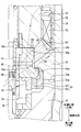
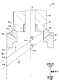
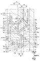
- FIG. 1 is a cross-sectional view of the fuel injection valve in the first embodiment
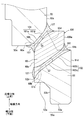
- FIG. 2 is an enlarged view around the movable core of FIG.
- FIG. 3 is an enlarged view around the first welded portion and the second welded portion in FIG.
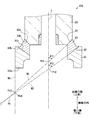
- FIG. 4 is a diagram for explaining an extension line of the boundary portion.
- FIG. 5 is a diagram illustrating the core unit.
- (a) is a view of attaching a support member to the body body
- (b) is a view of attaching a cover to the body body
- (c) is a movable structure attached to the nozzle body.
- FIG. 7 is a view of attaching a fixed core and a non-magnetic member to the nozzle body
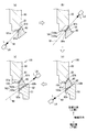
- (a) is a figure which heats from the inner side edge part of a 1st boundary part using a laser apparatus, and is welded
- (b) is a 1st fixed core, a nonmagnetic member, and a laser apparatus.
- (C) is a diagram for changing the positional relationship between the core unit and the laser device
- (d) is a diagram for changing the positional relationship between the core unit and the laser device.
- FIG. 8 is a diagram for explaining the surplus part of the core unit.
- FIG. 9 is a diagram illustrating the core unit in the second embodiment.
- FIG. 10 is a diagram for explaining a core unit in the third embodiment.
- FIG. 11 is an enlarged view around the first welded portion and the second welded portion in the fourth embodiment
- FIG. 12 is an enlarged view of the periphery of the cover in Modification 12.
- a fuel injection valve 1 shown in FIG. 1 is mounted on a gasoline engine that is an ignition type internal combustion engine, and directly injects fuel into each combustion chamber of a multi-cylinder engine.
- the fuel supplied to the fuel injection valve 1 is pumped by a fuel pump (not shown), and the fuel pump is driven by the rotational driving force of the engine.
- the fuel injection valve 1 includes a case 10, a nozzle body 20, a valve body 30, a movable core 41, fixed cores 50 and 51, a nonmagnetic member 60, a coil 70, a pipe connection portion 80, and the like.
- the case 10 is made of metal and has a cylindrical shape extending in the axial direction that is the direction in which the coil axis C that is the center line of the coil 70 extends.
- the coil axis C of the coil 70 coincides with the central axes of the case 10, the nozzle body 20, the valve body 30, the movable core 41, the fixed cores 50 and 51, and the nonmagnetic member 60.
- the axial direction corresponds to the axial direction.
- the nozzle body 20 is made of metal, and has a body main body portion 21 that is inserted and arranged in the case 10 and engages the case 10, and a nozzle portion 22 that extends from the body main body portion 21 to the outside of the case 10.
- the body main body portion 21 and the nozzle portion 22 both have a cylindrical shape extending in the axial direction, and a nozzle hole member 23 is attached to the tip of the nozzle portion 22.
- the injection hole member 23 is made of metal, and is fixed to the nozzle portion 22 by welding.
- the injection hole member 23 has a bottomed cylindrical shape extending in the axial direction, and an injection hole 23 a for injecting fuel is formed at the tip of the injection hole member 23.
- a seating surface 23 s on which the valve body 30 is seated is formed on the inner peripheral surface of the injection hole member 23.
- the valve element 30 is made of metal and has a cylindrical shape extending along the axial direction.
- the valve body 30 is assembled in the nozzle body 20 so as to be movable in the axial direction, and an annular flow extending in the axial direction between the outer peripheral surface 30a of the valve body 30 and the inner peripheral surface 20a of the nozzle body 20.
- a road is formed.
- This flow passage is referred to as a downstream passage F30.
- An annular seat surface 30s is formed at the end of the valve body 30 on the nozzle hole 23a side so as to be separated from and seated on the seating surface 23s.
- a connecting member 31 is fixedly attached to the end of the valve body 30 on the side opposite to the injection hole 23a, which is opposite to the injection hole 23a, by welding or the like. Furthermore, an orifice member 32 and a movable core 41 are attached to the end of the connecting member 31 on the side opposite to the injection hole.
- the connecting member 31 has a cylindrical shape extending in the axial direction, and the inside of the cylinder functions as a flow passage F23 through which fuel flows.
- the orifice member 32 is fixed to the inner peripheral surface of the connecting member 31 by welding or the like, and the movable core 41 is fixed to the outer peripheral surface of the connecting member 31 by welding or the like.
- a diameter-enlarged portion 31 a that expands in the radial direction is formed at the end of the connecting member 31 opposite to the injection hole. The end surface on the injection hole side of the enlarged diameter portion 31 a is engaged with the movable core 41, thereby preventing the connecting member 31 from coming out toward the injection hole with respect to the movable core 41.
- the orifice member 32 has a cylindrical shape extending in the axial direction, and the inside of the cylinder functions as a flow passage F21 through which fuel flows.
- an orifice 32a is formed as a constricting portion for narrowing the flow area by partially narrowing the passage area of the flow passage F21.
- a portion of the flow passage F21 that is restricted by the orifice 32a is referred to as a restriction flow passage F22.
- the throttle flow passage F22 is located on the central axis of the valve body 30.
- the length of the throttle flow path F22 is shorter than the diameter of the throttle flow path F22.
- a diameter-enlarged portion 32 b that expands in the radial direction is formed at the end of the orifice member 32 opposite to the injection hole. Since the end surface on the injection hole side of the enlarged diameter portion 32 b engages with the connecting member 31, the orifice member 32 is prevented from slipping out toward the injection hole with respect to the connecting member 31.
- the movable structure M has a moving member 35 and a pressing elastic member SP2.
- the moving member 35 is disposed in the flow path F ⁇ b> 23 inside the connecting member 31 so as to be relatively movable in the axial direction with respect to the orifice member 32.
- the moving member 35 has a cylindrical shape made of metal extending in the axial direction, and is disposed on the downstream side of the orifice member 32.
- a through-hole penetrating in the axial direction is formed in the central portion of the cylinder of the moving member 35. This through hole is a part of the flow passage F, communicates with the throttle flow passage F22, and functions as a sub-throttle flow passage 38 having a smaller passage area than the throttle flow passage F22.
- the moving member 35 includes a seal portion 36 formed with a seal surface 36a that covers the throttle flow passage F22, and an engagement portion 37 that engages with the pressing elastic member SP2.
- the engaging portion 37 has a smaller diameter than the seal portion 36, and a coil-shaped pressing elastic member SP ⁇ b> 2 is fitted into the engaging portion 37. Thereby, the movement of the pressing elastic member SP ⁇ b> 2 in the radial direction is restricted by the engaging portion 37.
- One end of the pressing elastic member SP2 is supported by the lower end surface of the seal portion 36, and the other end of the pressing elastic member SP2 is supported by the connecting member 31.
- the pressing elastic member SP ⁇ b> 2 is elastically deformed in the axial direction to apply an elastic force to the moving member 35, and the seal surface 36 a of the moving member 35 is pressed against the lower end surface of the orifice member 32 by the elastic force and closely contacts.
- the movable core 41 is a metal annular member.
- the movable core 41 has a movable inner portion 42 and a movable outer portion 43, both of which are annular.
- the movable inner portion 42 forms the inner peripheral surface of the movable core 41, and the movable outer portion 43 is disposed on the radially outer side of the movable inner portion 42.
- the movable core 41 has a movable upper surface 41 a facing the counter-injection hole side, and the movable upper surface 41 a forms the upper end surface of the movable core 41.
- a step is formed on the movable upper surface 41a.
- the movable outer portion 43 has a movable outer upper surface 43a facing the anti-injection hole side
- the movable inner portion 42 has a movable inner upper surface 42a facing the anti-injection hole side. Since 43a is closer to the nozzle hole than the movable inner upper surface 42a, a step is formed on the movable upper surface 41a.
- the movable inner upper surface 42a and the movable outer upper surface 43a are both orthogonal to the axial direction.
- the movable core 41 has a movable lower surface 41b facing the nozzle hole side, and this movable lower surface 41b is flat in the movable core 41 in a state straddling the movable inner portion 42 and the movable outer portion 43 in the radial direction. A lower end surface is formed. On the movable lower surface 41 b, no step is formed at the boundary between the movable inner portion 42 and the movable outer portion 43. In the axial direction, the height dimension of the movable outer portion 43 is smaller than the height dimension of the movable inner portion 42, and the movable core 41 is such that the movable outer portion 43 protrudes from the movable inner portion 42 to the outer peripheral side. It has a shape.
- the movable core 41 moves integrally with the connecting member 31, the valve body 30, the orifice member 32, and the sliding member 33 in the axial direction.
- the movable core 41, the connecting member 31, the valve body 30, the orifice member 32, and the sliding member 33 correspond to the movable structure M that moves integrally in the axial direction.
- the sliding member 33 is separate from the movable core 41, but is fixed to the movable core 41 by welding or the like. By making the sliding member 33 separate from the movable core 41, the sliding member 33 can be easily realized with a material and a material different from those of the movable core 41.
- the movable core 41 is made of a material having a higher magnetic property than the sliding member 33, and the sliding member 33 is made of a material having higher wear resistance than the movable core 41.
- the sliding member 33 has a cylindrical shape, and the cylindrical outer peripheral surface of the sliding member 33 functions as a sliding surface 33a that slides with respect to the member on the nozzle body 20 side.
- the surface on the side opposite to the injection hole of the sliding member 33 is joined to the surface on the injection hole side of the movable core 41 by welding or the like, so that fuel does not pass between the sliding member 33 and the movable core 41.
- a diameter-reduced portion 33 c that decreases in the radial direction is formed at the end of the sliding member 33 on the side opposite to the injection hole.
- a support member 24 is fixed to the body main body portion 21, and a reduced diameter portion 24 a that is reduced in the radial direction is formed on the support member 24.
- the sliding member 33 and the supporting member 24 are arranged side by side in the axial direction, and the distance between the sliding member 33 and the supporting member 24 increases or decreases as the movable structure M moves. This separation distance is minimized when the valve body 30 is in the closed state, but even in this case, the sliding member 33 is separated from the support member 24 toward the side opposite to the injection hole.
- the movable structure M is provided with a guide portion that supports the movable body M in the radial direction while sliding the movable structure M so as to be movable in the axial direction with respect to the nozzle body 20.
- the guide portions are provided at two locations in the axial direction, and the guide portion located on the injection hole 23a side in the axial direction is called the injection hole side guide portion 30b (see FIG. 1), and is located on the counter injection hole side.
- the guide part to be referred to is referred to as an anti-injection hole side guide part 31b.
- the injection hole side guide portion 30 b is formed on the outer peripheral surface of the valve body 30 and is slidably supported on the inner peripheral surface of the injection hole member 23.
- the anti-injection hole side guide portion 31 b is formed on the outer peripheral surface of the connecting member 31 and is slidably supported on the inner peripheral surface of the support member 24.
- the fixed cores 50 and 51 are fixedly arranged inside the case 10.
- the fixed cores 50 and 51 are made of an annular metal extending around the axial direction.
- the first fixed core 50 is provided on the inner peripheral side of the coil 70, and the outer peripheral surface of the first fixed core 50 and the inner peripheral surface of the coil 70 are opposed to each other.
- the first fixed core 50 has a first lower surface 50a facing the nozzle hole side.
- the first lower surface 50a forms a lower end surface of the first fixed core 50 and is orthogonal to the axial direction.
- the first fixed core 50 is provided on the side opposite to the injection hole of the movable core 41, and the first lower surface 50 a faces the movable inner upper surface 42 a of the movable core 41.
- the first fixed core 50 has a first inclined surface 50b and a first outer surface 50c.
- the first inclined surface 50b extends obliquely from the outer peripheral side end of the first lower surface 50a toward the anti-injection hole side.
- the first outer surface 50c is an outer peripheral surface of the first fixed core 50, and extends in the axial direction from the upper end portion of the first inclined surface 50b on the side opposite to the injection hole.
- the first fixed core 50 has a shape in which a protruding corner portion between the first lower surface 50a and the first outer surface 50c is chamfered by the first inclined surface 50b.
- the second fixed core 51 is provided on the nozzle hole side of the coil 70 and has an annular shape as a whole. It has the 2nd inner side part 52 and the 2nd outer side part 53, and all are circular.
- the second outer portion 53 forms the outer peripheral surface of the second fixed core 51, and the second inner portion 52 is disposed on the inner peripheral side of the second outer portion 53.
- the 2nd fixed core 51 has the 2nd lower surface 51a which faced the nozzle hole side, and the 2nd lower surface 51a forms the lower end surface of the 2nd fixed core 51, and is orthogonal to the axial direction.
- a step is formed on the second lower surface 51a.
- the second inner portion 52 has a second inner lower surface 52a facing the nozzle hole side
- the second outer portion 53 has a second outer lower surface 53a facing the nozzle hole side
- a step is formed on the second lower surface 51a.
- the height dimension of the second inner portion 52 is smaller than the height dimension of the second outer portion 53
- the second fixed core 51 is configured such that the second inner portion 52 is inward from the second outer portion 53. It has a shape that protrudes to the circumferential side.
- the second inner portion 52 of the second fixed core 51 is disposed on the side opposite to the injection hole with respect to the movable outer portion 43 of the movable core 41, and the second inner portion 52 and the movable outer portion 43 are aligned in the axial direction. It is out. In this case, the second inner lower surface 52a and the movable outer upper surface 43a face each other in the axial direction.
- the second outer portion 53 is provided on the side opposite to the injection hole of the body main body 21.
- the body main body 21 has an annular outer extending portion 211 that extends from the radially outer end toward the anti-injection hole.
- the outer extending portion 211 forms a step on the upper end surface of the body main body 21 by being separated from the radially inner end on the upper end surface of the body main body 21.
- the body main body 21 has a main body inner upper surface 21a, a main body outer upper surface 21b, a main body outer inner surface 21c, and a main body inner inner surface 21d, and the main body inner upper surface 21a and the main body outer upper surface 21b face the anti-injection hole side,
- the inner surface 21c and the main body inner inner surface 21d face the radially inner side.
- the main body outer upper surface 21 b is the upper end surface of the outer extending portion 211
- the main body outer inner surface 21 c is the inner peripheral surface of the outer extending portion 211.
- the main body inner inner surface 21 d extends from the radially inner end of the main body inner upper surface 21 a toward the nozzle hole side, and is the inner peripheral surface of the body main body 21.
- the main body inner upper surface 21 a is a portion of the upper end surface of the body main body 21 that is radially inward of the main body outer inner surface 21 c.
- the main body inner upper surface 21a and the main body outer upper surface 21b are orthogonal to the axial direction, and the main body outer inner surface 21c extends in parallel to the axial direction.
- the second outer lower surface 53a is overlapped with the main body outer upper surface 21b, and the second fixed core 51 and the body main body 21 are joined by welding at the overlapped portion.
- the second outer lower surface 53 a and the main body outer upper surface 21 b are included in a fixed boundary portion Q that is a boundary portion between the second fixed core 51 and the body main body portion 21.
- the width dimension of the second outer lower surface 53a and the width dimension of the main body outer upper surface 21b are the same, and the second outer lower surface 53a and the main body outer upper surface 21b overlap each other.
- the outer peripheral surface of the second outer portion 53 and the outer peripheral surface of the body main body portion 21 respectively overlap the inner peripheral surface of the case 10.
- the second fixed core 51 has a second upper surface 51b and a second inclined surface 51c.
- the second inclined surface 51c extends obliquely from the second inner inner surface 52b, which is the inner peripheral surface of the second inner portion 52, toward the counter-bore hole side, and the second upper surface 51b is the upper end of the second inclined surface 51c. It extends from the part in the radial direction.
- the second upper surface 51 b and the second inclined surface 51 c form the upper end surface of the second fixed core 51.
- the second inclined surface 51c is in a state straddling the second inner portion 52 and the second outer portion 53 in the radial direction.
- the second fixed core 51 has a shape in which the protruding corner portion between the second upper surface 51b and the second inner inner surface 52b is chamfered by the second inclined surface 51c.
- the second fixed core 51 has a second outer surface 51d.
- the second outer surface 51d is an outer peripheral surface of the second fixed core 51, and extends in the axial direction to connect the second lower surface 51a and the second upper surface 51b.
- the second outer surface 51d extends in parallel with the coil axis C.
- the outer peripheral surface of the second outer portion 53 is formed by the second outer surface 51d.
- the nonmagnetic member 60 is an annular metal member that extends around the axial direction, and is provided between the first fixed core 50 and the second fixed core 51.
- the nonmagnetic member 60 is weaker than the fixed cores 50 and 51 and the movable core 41, and is made of, for example, a nonmagnetic material.
- the body main body 21 is weaker than the fixed cores 50 and 51 and the movable core 41, and is formed of, for example, a nonmagnetic material.
- the fixed cores 50 and 51 and the movable core 41 have magnetism, and are formed of, for example, a ferromagnetic material.
- the nonmagnetic member 60 corresponds to a magnetic flux restricting portion that restricts the magnetic flux from passing through the movable core 41 and the fixed cores 50 and 51.
- the nonmagnetic member 60 can also be referred to as a short-circuit restricting portion that restricts the magnetic flux from passing through the fixed cores 50 and 51 without passing through the movable core 41.
- the fixed cores 50 and 51 and the movable core 41 can also be referred to as magnetic flux passage members that are likely to become magnetic flux passages.
- the body main body part 21 and the nozzle part 22 are integrally molded with a metal material, both the body main body part 21 and the nozzle part 22 are weak in magnetism.
- the nonmagnetic member 60 has an upper inclined surface 60a and a lower inclined surface 60b.
- the upper inclined surface 60a faces the anti-bore hole side while being inclined with respect to the axial direction
- the lower inclined surface 60b faces the nozzle hole side while being inclined with respect to the axial direction.
- At least a part of each of the first inclined surface 50b and the second inclined surface 51c is aligned in the axial direction, and the nonmagnetic member 60 is in a state of entering between the inclined surfaces 50b and 51c at least in the axial direction. It has become.
- the nonmagnetic member 60 has a nonmagnetic inner surface 60c and a nonmagnetic outer surface 60d.
- the nonmagnetic inner surface 60c connects the radially inner ends of the upper inclined surface 60a and the lower inclined surface 60b, and forms the inner peripheral surface of the nonmagnetic member 60 by facing the radially inner side. is doing.
- the nonmagnetic outer surface 60d connects the radially outer ends of the upper inclined surface 60a and the lower inclined surface 60b, and forms the outer peripheral surface of the nonmagnetic member 60 by facing the radially outer side. ing.
- the upper inclined surface 60a is overlapped with the first inclined surface 50b of the first fixed core 50, and the upper inclined surface 60a and the first inclined surface 50b are joined by welding such as laser welding.
- welding such as laser welding.
- the upper inclined surface 60 a and the first inclined surface 50 b are included in the first boundary portion Q ⁇ b> 1 that is a boundary portion between the first fixed core 50 and the nonmagnetic member 60.
- the first welded portion 101 includes the entire first boundary portion Q1. That is, the first welded portion 101 includes both end portions of the first boundary portion Q1.
- the first welded portion 101 is a portion of the first fixed core 50 and the nonmagnetic member 60 that is cooled and solidified after being melted and mixed by being heated.
- the lower inclined surface 60b is overlapped with the second inclined surface 51c of the second fixed core 51, and the lower inclined surface 60b and the second inclined surface 51c are joined by welding such as laser welding.
- the lower inclined surface 60 b and the second inclined surface 51 c are included in the second boundary portion Q ⁇ b> 2 that is a boundary portion between the second fixed core 51 and the nonmagnetic member 60.
- the second welded portion 102 includes the entire second boundary portion Q2. That is, the second welded portion 102 includes both end portions of the second boundary portion Q2.
- the 2nd welding part 102 is arrange
- the second welded portion 102 is a portion of the second fixed core 51 and the nonmagnetic member 60 that is cooled and solidified after being melted and mixed by being heated.
- the welded portions 101 and 102 are indicated by halftone dots in FIG. 3, and the boundary portions Q1 and Q2 are indicated by phantom lines in FIG.
- illustration of the welded portions 101 and 102 is omitted, but actually, as shown in FIG. 3, each of the fixed cores 50 and 51 and the nonmagnetic member 60. A part and the boundary portions Q1 and Q2 disappear due to the welded portions 101 and 102.
- the first boundary portion Q1 and the second boundary portion Q2 extend straight while being inclined with respect to the coil axis C.
- first extension line N1 the first angle ⁇ 1 between the first extension line N1 and the coil axis C is: It is smaller than 90 degrees.
- second extension line N2 an extension line obtained by extending the second boundary portion Q2 toward the coil axis C side and the opposite side is referred to as a second extension line N2
- the second angle ⁇ 2 between the second extension line N2 and the coil axis C is also set. It is smaller than 90 degrees.
- the first angle ⁇ 1 is smaller than the second angle ⁇ 2, and the first extension line N1 and the second extension line N2 intersect at the extension intersection Pn.
- the first boundary portion Q1 and the second boundary portion Q2 correspond to restriction boundary portions
- the first extension line N1 and the second extension line N2 correspond to boundary extension lines
- the first angle ⁇ 1 and the second angle ⁇ 2 are It corresponds to the tilt angle.
- the length dimension of the second boundary portion Q2 in the direction in which the second extension line N2 extends is larger than the length dimension of the first boundary portion Q1 in the direction in which the first extension line N1 extends.
- the length dimension of the second boundary portion Q2 is larger than the length dimension of the first boundary portion Q1.
- extension lines N1 and N2 are arranged on the injection hole side of any of the fixed cores 50 and 51 and the nonmagnetic member 60 on the side opposite to the base ends of the extension lines N1 and N2 across the coil axis C. Yes. That is, the extension lines N1 and N2 do not intersect any of the fixed cores 50 and 51 and the nonmagnetic member 60 at positions different from the boundary portions Q1 and Q2.
- the first angle ⁇ 1 of the first extension line N1 is larger than a predetermined first reference angle ⁇ 1n.
- an imaginary line connecting the nozzle hole side end portion of the first boundary portion Q1 and the nozzle hole side end portion of the second fixed core 51 is referred to as a first reference line L1n, and the first reference line L1n and the coil axis line.
- the angle with C is the first reference angle ⁇ 1n.
- the distance between the inner end portion Q1a of the first boundary portion Q1 in the radial direction and the inner end portion of the second outer lower surface 53a on the opposite side across the coil axis C is D1, and the first end in the axial direction is referred to as H1.
- the second angle ⁇ 2 of the second extension line N2 is larger than a predetermined second reference angle ⁇ 2n.
- an imaginary line connecting the nozzle hole side end of the second boundary portion Q2 and the nozzle hole side end of the second fixed core 51 is referred to as a second reference line L2n, and the second reference line L2n and the coil axis line.
- the smallest angle among the angles with C is defined as a second reference angle ⁇ 2n.
- the distance between the inner end portion Q2a of the second boundary portion Q2 in the radial direction and the inner end portion of the second outer lower surface 53a on the opposite side across the coil axis C is D2, and
- the separation distance between the inner end Q2a of the two boundary portions Q2 and the second outer lower surface 53a is referred to as H2.
- the upper limit value of the second angle ⁇ 2 is determined.
- first angle ⁇ 1 and the second angle ⁇ 2 are large angles such that the extension lines N1 and N2 do not intersect the valve body 30.
- the lower limit values of the first angle ⁇ 1 and the second angle ⁇ 2 are determined.
- the valve body 30 is in an open state.
- the separation distance D1 related to the first boundary portion Q1 and the separation distance D2 related to the second boundary portion Q2 have the same value, the separation distances D1 and D2 may be different from each other.
- the extended intersection point Pn is the coil axis C in the radial direction of the coil 70. It arrange
- the second axis intersection Pn2 where the second extension line N2 and the coil axis C intersect is The first extension line N1 and the coil axis C are arranged on the nozzle hole side from the first axis intersection Pn1.
- the second dip point Pn4 where the second extension line N2 and the outer surface extension line N3 intersect is counter-injected rather than the nozzle hole side than the first dip point Pn3 where the first extension line N1 and the outer surface extension line N3 intersect. It is arranged on the hole side.
- a cylindrical and metal stopper 55 is fixed to the inner peripheral surface of the first fixed core 50.
- the stopper 55 is a member that restricts the movable structure M from moving toward the counter-injection hole side by contacting the connecting member 31 of the movable structure M, and the lower end surface of the stopper 55 has a diameter-enlarged portion of the connecting member 31.
- the movement of the movable structure M is regulated by contacting the upper end surface of 31a.
- the stopper 55 protrudes further toward the injection hole than the first fixed core 50. For this reason, even when the movement of the movable structure M is restricted by the stopper 55, a predetermined gap is formed between the fixed cores 50 and 51 and the movable core 41.
- This gap is formed between the first lower surface 50a and the movable inner upper surface 42a, or between the second inner lower surface 52a and the movable outer upper surface 43a.
- the separation distance between the first lower surface 50a and the movable inner upper surface 42a and the separation distance between the second inner lower surface 52a and the movable outer upper surface 43a are made larger than actual. It is shown.
- a coil 70 is disposed on the radially outer side of the nonmagnetic member 60 and the fixed core 50.
- the coil 70 is wound around a resin bobbin 71.
- the bobbin 71 has a cylindrical shape centering on the axial direction. Therefore, the coil 70 is disposed in an annular shape extending around the axial direction.
- the bobbin 71 is in contact with the first fixed core 50 and the nonmagnetic member 60.
- An opening, an upper end surface, and a lower end surface on the outer peripheral side of the bobbin 71 are covered with a resin cover 72.
- a yoke 75 is provided between the cover 72 and the case 10.
- the yoke 75 is disposed on the side opposite to the injection hole of the second fixed core 51 and is in contact with the second upper surface 51 b of the second fixed core 51.
- the yoke 75 has magnetism like the fixed cores 50 and 51 and the movable core 41, and is made of, for example, a ferromagnetic material.
- the fixed cores 50 and 51 and the movable core 41 are disposed at positions where they come into contact with fuel, such as forming a flow path, and have oil resistance.
- the yoke 75 is disposed at a position where it does not come into contact with fuel, such as not forming a flow passage, and does not have oil resistance. For this reason, the yoke 75 has higher magnetic properties than the fixed cores 50 and 51 and the movable core 41.
- a cover 90 that covers the fixed boundary portion Q between the second fixed core 51 and the body main body 21 is provided on the inner peripheral side of the second fixed core 51 and the body main body 21.
- the cover 90 is annular and covers the entire fixed boundary portion Q in the circumferential direction of the second fixed core 51.
- the cover 90 projects radially inward from the second fixed core 51 and the body main body 21 in a state where the cover 90 straddles the fixed boundary portion Q in the axial direction.
- the body main body portion 21 has a main body cutout portion N21
- the second fixed core 51 has a second cutout portion N51
- the cover 90 enters the cutout portions N21 and N51. ing.
- a main body notch N21 is formed by a main body outer inner surface 21c and a main body inner upper surface 21a.
- the main body notch N21 is opened to the injection hole side in the axial direction and opened radially inward.
- the main body cutout portion N21 has a cutout inclined surface N21a that connects the main body outer inner surface 21c and the main body inner upper surface 21a, and has a shape in which a corner portion is chamfered by the cutout inclined surface N21a.
- the second notch N51 is formed by the second inner lower surface 52a and the second outer inner surface 53b.
- the second outer inner surface 53 b extends in the axial direction in a state facing the inner side in the radial direction, and forms an inner peripheral surface of the second outer portion 53.
- the second notch N51 is formed by a step on the second lower surface 51a of the second fixed core 51, and is open to the side opposite to the injection hole in the axial direction and open radially inward.
- the second cutout portion N51 has a cutout inclined surface N51a that connects the second inner lower surface 52a and the second outer inner surface 53b, and has a shape in which a corner portion is chamfered by the cutout inclined surface N51a. ing.
- the main body cutout portion N21 and the second cutout portion N51 communicate with each other in the axial direction, and the cover 90 is disposed between the second inner lower surface 52a and the main body inner upper surface 21a at the cutout portions N21, N51. .
- the main body outer inner surface 21c of the body main body 21 and the second outer inner surface 53b of the second fixed core 51 form the same plane in the axial direction.
- a cover outer surface 90a that is an outer peripheral surface of the cover body 90 is overlapped with both the main body outer inner surface 21c and the second outer inner surface 53b in a state of covering the fixed boundary portion Q from the inner side. However, the cover outer surface 90a does not overlap with the cutout inclined surfaces N21a and N51a.
- the cover body 90 has a cover inner portion 92 and a cover outer portion 91.
- the cover outer portion 91 forms a cover outer surface 90 a, and the cover inner portion 92 is disposed on the radially inner side of the cover outer portion 91.
- the cover 90 has a cover upper surface 90b facing the counter-bore hole side and a cover lower surface 90c facing the nozzle hole side.
- the covering upper surface 90b and the covering lower surface 90c have the same area.
- a step is formed on the upper surface 90b of the cover because the upper end surface of the cover inner side 92 on the side opposite to the injection hole is disposed closer to the nozzle hole side than the upper end surface of the cover outer side 91 on the side opposite to the injection hole.
- the cover lower surface 90c forms a flat lower end surface on the nozzle hole side of the cover 90, and no step is formed at the boundary between the cover inner portion 92 and the cover outer portion 91 in the cover lower surface 90c.
- a cover notch N90 is formed by a step on the cover upper surface 90b.
- a protruding corner portion on the outer peripheral side on the nozzle hole side of the movable core 41 enters.
- the end of the cover outer portion 91 on the side opposite to the injection hole is disposed between the movable outer portion and the second outer portion 53 in the radial direction.
- the cover inner portion 92 is disposed on the nozzle hole side of the second outer portion 53 in the axial direction.
- the cover upper surface 90 b is separated from the movable lower surface 41 b of the movable core 41 and the second inner lower surface 52 a of the second fixed core 51 toward the injection hole, and the cover lower surface 90 c is the main body of the body main body 21. It is spaced apart from the inner upper surface 21a to the side opposite to the injection hole.
- the cover outer portion 91 enters between the second outer portion 53 and the movable outer portion 43 in the radial direction
- the cover inner portion 92 enters between the movable core 41 and the main body inner upper surface 21a in the axial direction. Yes.
- the separation distance between the cover inner portion 92 and the movable core 41 in the axial direction increases and decreases with the movement of the movable structure M, but the valve body 30 is movable on the cover inner surface 92 when the valve body 30 is seated on the seating surface 23s. There is no contact with the core 41.
- the space between the cover upper surface 90b and the movable core 41 and the second fixed core 51 is referred to as an upper chamber S1, and the space between the cover lower surface 90c and the body main body 21 is covered with the lower chamber S2. Called.
- the cover upper chamber S1 and the cover lower chamber S2 are formed by the cover 90 being in a state of entering the inside of the main body cutout portion N21 and the second cutout portion N51.
- the cover upper chamber S1 is included in the flow passage F26s, and the cover lower chamber S2 is included in the flow passage F31.
- the covering body 90 is formed by a covering member 93 and a counter member 94.
- the covering member 93 and the facing member 94 are both metal annular members, and the facing member 94 is provided on the inner peripheral side of the covering member 93.
- the opposing member 94 is in a state of being fitted to the inner peripheral surface of the covering member 93, and the opposing member 94 and the covering member 93 are joined together by welding or the like at the boundary between them.
- the cover member 93 includes a portion near the outer peripheral surface included in the cover outer portion 91 and a portion closer to the inner peripheral surface included in the cover inner portion 92.
- the entire facing member 94 is included in the covering inner portion 92.
- the facing member 94 constitutes a facing portion and is supported by a covering member 93.
- the opposing member 94 has an opposing inner surface 94a and is disposed on the outer peripheral side of the sliding member 33 in the radial direction.
- the opposed inner surface 94a faces the sliding surface 33a of the sliding member 33 in the radial direction, and the sliding surface 33a of the sliding member 33 slides with respect to the opposed inner surface 94a.
- the above-mentioned member on the nozzle body 20 side that slides the sliding surface 33 a is the opposing member 94.
- the opposed inner surface 94a is an inner peripheral surface of the opposed member 94, and the height dimension of the opposed inner surface 94a is smaller than the height dimension of the sliding surface 33a in the axial direction. Both the opposing inner surface 94a and the sliding surface 33a extend parallel to the axial direction.
- the diameter of the sliding surface 33a is slightly smaller than the diameter of the opposing inner surface 94a. That is, the position of the sliding surface 33a in the direction orthogonal to the sliding direction of the sliding member 33 is located inside the outermost peripheral position of the opposed inner surface 94a, that is, on the coil axis C side.
- the opposing member 94 also exhibits a function as a guide portion that guides the moving direction of the movable structure M when the sliding member 33 slides on the opposing member 94.
- the opposing inner surface 94a can also be referred to as a guide surface or a guide surface. Further, the opposing member 94 constitutes a guide part.
- the covering member 93 and the facing member 94 are weaker in magnetism than the fixed cores 50 and 51 and the movable core 41, as in the case of the nonmagnetic member 60 and the body main body 21, and are made of, for example, a nonmagnetic material. For this reason, the covering member 93 and the opposing member 94 are unlikely to become a magnetic flux passage.
- the opposing member 94 is preferably formed using a material having high hardness and strength so that the opposing inner surface 94a is not easily worn or deformed even when the sliding member 33 is slid.
- the opposing member 94 is more likely to be a magnetic flux path than the covering member 93 or the like, but the opposing member 94 is still more magnetic than the fixed cores 50 and 51 and the movable core 41. Therefore, it is less likely to be a magnetic flux path than the fixed cores 50 and 51.
- a pipe connection portion 80 which forms a fuel inflow port 80 a and is connected to an external pipe.
- the pipe connection portion 80 is made of metal and is formed of a metal member integrated with the fixed core 50.
- the fuel pressurized by the high-pressure pump is supplied to the fuel injection valve 1 from the inflow port 80a.
- a fuel flow passage F11 extending in the axial direction is formed inside the pipe connection portion 80, and a press-fitting member 81 is press-fitted and fixed in the flow passage F11.
- An elastic member SP1 is disposed on the injection hole side of the press-fitting member 81.
- One end of the elastic member SP1 is supported by the press-fitting member 81, and the other end of the elastic member SP1 is supported by the enlarged diameter portion 32b of the orifice member 32. Therefore, the elastic deformation of the elastic member SP1 when the valve body 30 is opened to the full lift position, that is, when the connecting member 31 is in contact with the stopper 55, according to the press-fitting amount of the press-fitting member 81, that is, the fixed position in the axial direction.
- the amount is specified. That is, the valve closing force as the set load by the elastic member SP1 is adjusted by the press-fitting amount of the press-fitting member 81.
- a fastening member 83 is disposed on the outer peripheral surface of the pipe connection portion 80.
- the fastening member 83 is fastened to the case 10 by fastening the screw portion formed on the outer peripheral surface of the fastening member 83 to the screw portion formed on the inner peripheral surface of the case 10. Due to the axial force generated by this fastening, the pipe connection portion 80, the fixed cores 50 and 51, the nonmagnetic member 60 and the body main body portion 21 are sandwiched between the bottom surface of the case 10 and the fastening member 83.
- the pipe connection part 80, the fixed core 50, the nonmagnetic member 60, the nozzle body 20, and the injection hole member 23 correspond to a body B having a flow passage F through which the fuel supplied to the inflow port 80a flows to the injection hole 23a. It can be said that the movable structure M described above is accommodated in the body B in a slidable state.
- a magnetic field is generated around the coil 70.
- a magnetic field circuit through which magnetic flux passes through the fixed cores 50 and 51, the movable core 41, and the yoke 75 is formed by energization, and the movable core 41 is fixed by the magnetic force generated by the magnetic circuit. 50, 51.
- the first fixed core 50 and the movable core 41 are attracted to each other because the first lower surface 50a and the movable inner upper surface 42a serve as magnetic flux paths.
- the second fixed core 51 and the movable core 41 are attracted to each other because the second inner lower surface 52a and the movable outer upper surface 43a serve as a magnetic flux path.
- the first lower surface 50a, the movable inner upper surface 42a, the second inner lower surface 52a, and the movable outer upper surface 43a can also be referred to as suction surfaces.
- the movable inner upper surface 42a corresponds to a first suction surface
- the movable outer upper surface 43a corresponds to a second suction surface.
- the nonmagnetic member 60 does not become a magnetic flux path, thereby preventing the first fixed core 50 and the second fixed core 51 from being magnetically short-circuited.
- the attractive force between the movable core 41 and the first fixed core 50 is generated by the magnetic flux passing through the movable inner upper surface 42a and the first lower surface 50a, and the attractive force between the movable core 41 and the second fixed core 51 is the movable outer upper surface 43a and the first fixed core 50. It is generated by the magnetic flux passing through the second lower surface 51a.
- the magnetic flux passing through the fixed cores 50 and 51 and the movable core 41 includes not only the yoke 75 but also the magnetic flux passing through the case 10.
- the magnetic flux of the body main body 21 and the cover body 90 is suppressed from passing through the body main body 21 and the cover body 90 due to the fact that the magnetism of the body main body 21 and the cover body 90 is weaker than that of the fixed cores 50 and 51 and the like.
- the opposing member 94 has a certain degree of magnetism by giving priority to hardness and strength that can withstand sliding of the sliding member 33, but the magnetism of the covering member 93 is sufficiently weak. For this reason, the covering member 93 suppresses the magnetic flux passing through the second fixed core 51 from reaching the facing member 94.
- the closing force by the elastic member SP1 the valve closing force by the fuel pressure, and the valve opening force by the magnetic force described above act on the movable structure M. Since the valve opening force is set to be larger than the valve closing force, the movable core 41 moves to the opposite injection hole side together with the valve body 30 when a magnetic force is generated with energization. As a result, the valve body 30 is opened, the seat surface 30s is separated from the seating surface 23s, and the high-pressure fuel is injected from the injection hole 23a.
- the high-pressure fuel supplied from the high-pressure pump to the fuel injection valve 1 flows in from the inflow port 80a and flows along the cylindrical inner peripheral surface of the pipe connection portion 80, and the flow passage F12 along the cylindrical inner peripheral surface of the press-fitting member 81. Then, it flows in order through the flow path F13 in which the elastic member SP1 is accommodated (see FIG. 1).
- These flow passages F11, F12, and F13 are collectively referred to as an upstream passage F10, and the upstream passage F10 is outside and upstream of the movable structure M in the entire flow passage F existing inside the fuel injection valve 1. Located in.
- a flow path formed by the movable structure M is referred to as a movable flow path F20, and a flow path positioned on the downstream side of the movable flow path F20 is referred to as a downstream path F30.
- the movable flow passage F20 flows by dividing the fuel flowing out from the flow passage F13 into a main passage and a sub passage.
- the main passage and the sub passage are arranged independently. Specifically, the main passage and the sub passage are arranged in parallel, and the fuel that has branched and flowed into each of them merges in the downstream passage F30.
- the main passage is a passage through which fuel flows in the order of a flow passage F21 along the cylindrical inner peripheral surface of the orifice member 32, a throttle flow passage F22 by the orifice 32a, and a flow passage F23 along the cylindrical inner peripheral surface of the connecting member 31. And the fuel of the flow path F23 flows into the downstream path F30 which is the flow path F31 along the cylindrical outer peripheral surface of the connection member 31 through the through-hole penetrating the connection member 31 in the radial direction.
- the downstream passage F ⁇ b> 30 has a covered lower chamber S ⁇ b> 2 on the nozzle hole side of the covered body 90, and the covered lower chamber S ⁇ b> 2 communicates with a separated portion between the support member 24 and the sliding member 33. .
- the sub passages include a flow passage F24s along the cylindrical outer peripheral surface of the orifice member 32, a flow passage F25s which is a gap between the movable core 41 and the fixed core 50, a flow passage F26s extending on the outer peripheral side of the movable core 41, and a sliding surface 33a. This is a passage through which fuel flows in the order of the sliding flow passage F27s along.
- the flow passage F26s has a cover upper chamber S1 on the side opposite to the injection hole of the cover 90.
- the flow path F26s includes a gap between the movable core 41, the first fixed core 50, the nonmagnetic member 60, the second fixed core 51, and the cover 90.
- the gap portion between the first lower surface 50a and the movable inner upper surface 42a and the gap portion between the second inner lower surface 52a and the movable outer upper surface 43a are also included in the gap as described above.
- the sub passage is formed between the body main body portion 21 and the movable structure M, and the body main body portion 21 corresponds to a passage forming portion that forms the sub passage.
- the sliding flow passage F27s can also be referred to as a separate flow passage, and the fuel in the sliding flow passage F27s flows into the downstream passage F30 that is the flow passage F31 along the cylindrical outer peripheral surface of the connecting member 31.
- the passage area of the sliding flow passage F27s is smaller than the passage area of the flow passage F26s extending on the outer peripheral side of the movable core 41. That is, the degree of restriction in the sliding flow path F27s is set larger than the degree of restriction in the flow path F26s.
- the upstream side of the sub passage is connected to the upstream side of the throttle flow passage F22.
- the downstream side of the sub passage is connected to the downstream side of the throttle flow passage F22.
- the sub passage connects the upstream side and the downstream side of the throttle flow passage F22 without passing through the throttle flow passage F22.
- the fuel that has flowed into the movable flow path F20 from the flow path F13 that is the upstream path F10 branches into a flow path F21 that is the upstream end of the main path and a flow path F24s that is the upstream end of the sub-passage, and then the downstream path It merges in the flow path F31 which is F30.
- each of the movable core 41, the connecting member 31, and the orifice member 32 is formed with a through hole 45 penetrating in the radial direction.
- These through holes 45 function as a flow passage F28s that connects the flow passage F21 along the inner peripheral surface of the orifice member 32 and the flow passage F26s along the outer peripheral surface of the movable core 41.
- the flow passage F28s is configured to reduce the flow rate of the fuel flowing through the sliding flow passage F27s, that is, the flow rate of the sub-passage when the connection member 31 contacts the stopper 55 and the communication between the flow passage F24s and the flow passage F25s is blocked.
- a passage to be secured Since the flow passage F28s is positioned on the upstream side of the throttle flow passage F22, the flow passages F25s, F26s, and F28s become the upstream region, and a pressure difference with the downstream region is generated.
- the fuel flowing out of the movable flow path F20 flows into the flow path F31 along the cylindrical outer peripheral surface of the connecting member 31, and then the flow path F32, which is a through hole penetrating the reduced diameter portion 24a of the support member 24 in the axial direction. It flows through the flow path F33 along the outer peripheral surface of the valve body 30 in order (see FIG. 2).
- the valve body 30 opens, the high-pressure fuel in the flow passage F33 passes between the seat surface 30s and the seating surface 23s and is injected from the injection hole 23a.
- the flow passage along the sliding surface 33a described above is called a sliding flow passage F27s, and the passage area of the sliding flow passage F27s is smaller than the passage area of the throttle flow passage F22. That is, the degree of restriction in the sliding flow path F27s is set to be larger than the degree of restriction in the restriction flow path F22.
- the main passage has the smallest passage area of the throttle flow passage F22, and the sub passage has the smallest passage area in the sliding flow passage F27s.
- the main passage is easier to flow between the main passage and the sub passage in the movable flow passage F20, and the restriction degree of the main passage is specified by the restriction degree of the orifice 32a, and the flow rate of the main passage is determined by the orifice 32a. It is adjusted by.
- the degree of restriction of the movable flow path F20 is specified by the degree of restriction at the orifice 32a, and the flow rate of the movable flow path F20 is adjusted by the orifice 32a.
- the passage area on the seat surface 30s in the flow passage F, and the passage area in the full lift state in which the valve body 30 has moved most in the valve opening direction is referred to as a seat passage area.
- the passage area of the throttle flow passage F22 by the orifice 32a is set larger than the sheet passage area. That is, the degree of restriction by the orifice 32a is set smaller than the degree of restriction on the seat surface 30s during full lift.
- the seat passage area is set larger than the passage area of the nozzle hole 23a. That is, the degree of restriction by the orifice 32a and the degree of restriction at the sheet surface 30s are set to be smaller than the degree of restriction at the nozzle hole 23a.
- the seat passage area is set larger than the total passage area of all the nozzle holes 23a.
- the moving member 35 will be described.
- the moving member 35 resists the elastic force of the pressing elastic member SP2 and the moving member 35 becomes an orifice member. Get away from 32.
- the downstream side fuel pressure of the moving member 35 becomes higher than the upstream side fuel pressure by a predetermined amount or more as the valve body 30 moves in the valve closing direction, the moving member 35 is seated on the orifice member 32.
- a flow passage through which fuel flows is formed in the gap between the outer peripheral surface of the moving member 35 and the inner peripheral surface of the connecting member 31.
- the fuel flowing out from the throttle flow passage F22 to the flow passage F23 is separated from the sub throttle flow passage 38. It branches and flows to the outer peripheral flow passage F23a.
- the total passage area of the sub-throttle flow passage 38 and the outer peripheral flow passage F23a is larger than the passage area of the restriction flow passage F22. Therefore, in the state where the moving member 35 is separated, the flow rate of the movable flow passage F20 is specified by the degree of restriction in the restriction flow passage F22.
- the fuel that has flowed out from the throttle flow passage F22 to the flow passage F23 flows through the sub-throttle flow passage 38 and does not flow into the outer peripheral flow passage F23a.
- the passage area of the sub throttle passage 38 is smaller than the passage area of the throttle passage F22. Therefore, in the state where the moving member 35 is seated, the flow rate of the movable flow passage F20 is specified by the degree of restriction in the sub-throttle flow passage 38. Accordingly, the moving member 35 is seated on the orifice member 32 to cover the throttle flow passage F22 to increase the degree of throttle, and by moving away from the orifice member 32, the throttle flow passage F22 is opened to reduce the throttle degree. .
- valve body 30 If the valve body 30 is moving in the valve opening direction, there is a high probability that the upstream side fuel pressure of the moving member 35 is higher than the downstream side fuel pressure by a predetermined amount or more and the moving member 35 is separated. However, if the valve body 30 is in the full lift state in which the valve body 30 has moved most in the valve opening direction and the valve body 30 has stopped moving, there is a high probability that the moving member 35 will be seated.
- the downstream side fuel pressure of the moving member 35 is higher than the upstream side fuel pressure by a predetermined level or more, and the probability that the moving member 35 is seated is high.
- the partial lift injection is performed as the injection that switches the valve body 30 from the valve opening operation to the valve closing operation without moving to the full lift position.
- the downstream fuel pressure of the moving member 35 is higher than the upstream fuel pressure by a predetermined amount or more, and the probability that the moving member 35 is seated is high.
- the moving member 35 is not always opened during the valve opening operation of the valve body 30, and the moving member is at least in the period immediately after the valve opening in the rising period in which the valve body 30 moves in the valve opening direction. 35 is seated. Further, the moving member 35 is not always seated during the valve closing operation of the valve body 30, and the moving member 35 is at least in the period immediately before the valve closing in the descending period in which the valve body 30 moves in the valve closing direction. Is seated. Therefore, in the period immediately after the valve opening and in the period immediately before the valve closing, the moving member 35 is seated and the entire amount of the fuel flows through the sub-throttle flow passage 38, so that the moving member 35 is separated from the period. The degree of restriction in the movable flow path F20 increases.
- the throttle flow passage F22 and the sliding flow passage F27s are arranged in parallel, and the passage area of the sliding flow passage F27s is set smaller than the passage area of the throttle flow passage F22. Therefore, the flow passage F is divided into an upstream region and a downstream region with the orifice 32a and the sliding flow passage F27s as a boundary.
- the upstream region is a region upstream of the fuel flow at the time of injection with respect to the orifice 32a.
- the upstream side of the sliding surface 33a in the movable flow path F20 also belongs to the upstream region. Therefore, the flow passages F21, F24s, F25s, F26s, F28s and the upstream passage F10 in the movable flow passage F20 correspond to the upstream region.
- the downstream region is a region on the downstream side of the fuel flow at the time of injection with respect to the orifice 32a. Note that the downstream side of the sliding surface 33a in the movable flow path F20 also belongs to the downstream region. Therefore, the flow passage F23 and the downstream passage F30 in the movable flow passage F20 correspond to the downstream region.
- the flow rate of the fuel flowing through the movable flow passage F20 is throttled by the orifice 32a, so that the upstream fuel pressure PH, which is the fuel pressure in the upstream region, and the downstream region A pressure difference is generated between the fuel pressure and the downstream fuel pressure PL (see FIG. 4). Accordingly, when the valve body 30 is changing from the closed state to the open state, when the valve body 30 is changing from the open state to the closed state, and when the valve body 30 is held at the full lift position, the throttle flow is reduced. The fuel flows in the path F22 and the pressure difference is generated.
- valve opening of the valve body 30 does not disappear simultaneously with switching from valve opening to valve closing, but when the predetermined time passes after valve closing, the upstream fuel pressure PH and the downstream fuel pressure PL are the same. become. On the other hand, when switching from valve closing to valve opening in a state where the pressure difference does not occur, the pressure difference immediately occurs at the switching timing.
- the fuel in the upstream region is compressed by being pushed by the movable structure M, so that the upstream fuel pressure PH increases.
- the fuel in the upstream region pushed by the movable structure M is pushed out to the downstream region while being throttled by the orifice 32a, so the downstream fuel pressure PL is lower than the upstream fuel pressure PH.
- fuel flows through the throttle flow passage F22 toward the injection hole.
- the fuel in the downstream region is compressed by being pushed by the movable structure M, so the downstream fuel pressure PL rises.
- the upstream fuel pressure PH becomes lower than the downstream fuel pressure PL.
- the fuel flows through the throttle flow passage F22 toward the counter injection hole.
- a method for manufacturing the fuel injection valve 1 will be described with reference to FIGS. Here, the assembly procedure after manufacturing each component will be mainly described.
- a support member 24 is attached to the body main body 21 of the nozzle body 20 as shown in FIG.
- the support member 24 is inserted inside the body main body 21, and the body main body 21 and the support member 24 are fixed by welding or the like.
- the cover 90 is attached to the body main body 21.
- the cover 90 is manufactured in advance by inserting the facing member 94 inside the covering member 93 and fixing the covering member 93 and the facing member 94 by welding or the like. Then, the cover body 90 is inserted into the body main body 21.
- the length dimension of the portion entering the body main body portion 21 and the length dimension of the portion protruding from the body main body portion 21 are made substantially the same.
- the movable structure M is mounted on the nozzle body 20 as shown in FIG.
- the movable structure M is manufactured in advance by assembling the movable core 41, the connecting member 31, the valve body 30, the orifice member 32, the sliding member 33, the moving member 35, and the pressing elastic member SP2.
- the movable structure M is mounted on the nozzle body 20 by inserting the sliding member 33 inside the cover body 90 while inserting the valve body 30 into the nozzle portion 22.
- the fixed cores 50 and 51 and the nonmagnetic member 60 are attached to the nozzle body 20.
- the fixed cores 50 and 51 are attached to the nonmagnetic member 60, and the core unit 105 is manufactured in advance by fixing the nonmagnetic member 60 and the fixed cores 50 and 51 by welding or the like. The manufacturing procedure of the core unit 105 will be described later.
- the second fixed core 51 is attached to the body main body 21 and the cover 90.
- the second lower surface 51 a of the second fixed core 51 is overlapped with the main body outer upper surface 21 b of the body main body 21 while the end of the cover 90 is inserted inside the second fixed core 51.
- the fixed boundary part Q exists between the second fixed core 51 and the body main body part 21.
- spatters such as slag and metal particles generated by welding may scatter in the internal space of the second fixed core 51 and the body main body 21 through the fixed boundary portion Q.
- the cover 90 covers the fixed boundary portion Q from the inner peripheral side, even if spatter is generated during welding, the spatter hits the cover 90 and does not fly further to the inner peripheral side. Become. For this reason, the cover 90 prevents spatter from jumping out from the fixed boundary portion Q to the inner peripheral side.
- the fuel injection valve is mounted by attaching the coil 70, the yoke 75, etc. to the first fixed core 50, etc., and housing them together in the case 10.
- the non-magnetic member 60 is attached to the first fixed core 50, and the first fixed core 50 and the non-magnetic member 60 are aligned. And the 1st welding part 101 which joins the 1st fixed core 50 and the nonmagnetic member 60 is formed by welding with respect to the 1st boundary part Q1.
- welding is performed by applying heat from the inner end portion Q1a of the first boundary portion Q1 using a laser device LA that emits a laser L.
- the laser device LA is installed on the first fixed core 50 and the nonmagnetic member 60 so that the laser L reaches the first boundary portion Q1 along the first extension line N1.
- the inner end Q1a of the first boundary portion Q1 with the laser L from the laser device LA about the entire circumference of the first boundary portion Q1, the inner side extending from the inner end portion Q1a toward the outer end portion Q1b.
- a welded portion 101a is formed.
- Laser irradiation by the laser device LA is continuously performed in the direction in which the first extension line N1 extends until the inner welded portion 101a reaches the position near the outer end Q1b beyond the center of the first boundary portion Q1. . Note that it is difficult for the inner laser welded portion 101a to reach the outer end Q1b by the normal laser irradiation method and duration.
- the inner welded portion 101a When laser L is irradiated for welding at the stage before laser welding, the inner welded portion 101a is located at the center of the first boundary portion Q1 by applying heat at how much intensity and temperature of the laser L and for how long. Test whether it exceeds the limit. Based on the test results, the intensity and temperature of the laser L applied during laser welding and the duration of laser irradiation are set. Thereby, it can suppress that the inner side welding part 101a does not exceed the center of the 1st boundary part Q1.
- the positional relationship between the first fixed core 50 and the nonmagnetic member 60 and the laser device LA is changed.
- the outer end Q1b of the first boundary portion Q1 is irradiated with the laser L from the laser device LA along the first extension line N1 to apply heat, so that the outer end Q1b is directed toward the inner welded portion 101a.
- An extended outer welded portion 101b is formed.
- Laser irradiation by the laser device LA is continuously performed in a direction in which the first extension line N1 extends until the outer welded portion 101b reaches the inner welded portion 101a at an intermediate position of the first boundary portion Q1.
- the 1st welding part 101 is formed in the state which the outer side welding part 101b and the inner side welding part 101a integrated.
- the outer welded portion 101b As for the outer welded portion 101b, a test is performed to determine how much heat is applied at the intensity and temperature of the laser L for how long the outer welded portion 101b reaches the inner welded portion 101a. That is, the intensity, temperature, and duration of laser irradiation are tested for conditions under which the outer welded portion 101b reaches at least the center of the first boundary portion Q1. Based on the test results, the intensity and temperature of the laser L applied during laser welding and the duration of laser irradiation are set. Thereby, it can suppress that the outer side welding part 101b has not reached
- the second fixed core 51 is mounted on the nonmagnetic member 60, and the nonmagnetic member 60 and the second fixed core 51 are aligned with respect to the core unit 105.
- the 2nd welding part 102 which joins the nonmagnetic member 60 and the 2nd fixed core 51 is formed by welding with respect to the 2nd boundary part Q2.
- the positional relationship between the core unit 105 and the laser device LA is changed. Then, the laser L from the laser device LA is irradiated to the inner end portion Q2a of the second boundary portion Q2 along the second extension line N2 to apply heat, so that the inner end portion Q2a is directed toward the outer end portion Q2b. An extending inner weld 102a is formed. Laser irradiation by the laser device LA is continuously performed in the direction in which the second extension line N2 extends until the inner welded portion 102a passes the center of the second boundary portion Q2 and reaches a position near the outer end portion Q2b. . Note that, similarly to the first boundary portion Q1, also in the second boundary portion Q2, it is difficult to cause the inner welded portion 102a to reach the outer end portion Q2b by a normal laser irradiation method and duration.
- the positional relationship between the core unit 105 and the laser device LA is changed. And by irradiating the outer end Q2b of the second boundary portion Q2 with the laser L from the laser device LA along the second extension line N2, and applying heat, the outer end Q2b is directed toward the inner welded portion 102a. An extended outer weld 102b is formed. Laser irradiation by the laser device LA is continuously performed in the direction in which the second extension line N2 extends until the outer welded portion 102b reaches the inner welded portion 102a at an intermediate position of the second boundary portion Q2. Thereby, the 2nd welding part 102 is formed in the state which the outer side welding part 102b and the inner side welding part 102a integrated.
- the intensity, temperature, and duration of laser irradiation are tested. Thereby, also about the 2nd boundary part Q2, it can suppress that the inner side welding part 102a does not exceed the center, and that the outer side welding part 102b has not reached
- a shaping work for adjusting the shape of the core unit 105 is performed.
- the state of the core unit 105 after welding is such that the surplus portions 106a and 107 are attached to the fixed cores 50 and 51 and the nonmagnetic member 60, as shown in FIG. In FIG. 7, the surplus portions 106a and 107 are not shown.
- the original member 106 as a part forming the nonmagnetic member 60 is welded to the fixed cores 50 and 51.
- the original member 106 has a shape in which a member surplus portion 106 a is integrated with a portion where the nonmagnetic member 60 is formed.
- the member surplus portion 106a has a reference surface that serves as a reference for the inclination angle of the inclined surfaces 60a and 60b when, for example, the upper inclined surface 60a and the lower inclined surface 60b of the nonmagnetic member 60 are formed. For this reason, when the original member 106 has the member surplus part 106a, the precisions, such as the inclination angle of inclined surface 60a, 60b, can be improved.
- a surplus welded portion 107 such as a bead accompanying the welding adheres to the boundary portions Q1 and Q2.
- the welding surplus portion 107 attached to the inner end portion Q1a of the first boundary portion Q1 is in a state straddling the first fixed core 50 and the nonmagnetic member 60, and the welding surplus portion 107 is scraped off.
- the first lower surface 50a and the nonmagnetic inner surface 60c are formed by removing the above.
- the welding surplus part 107 adhering to the inner end Q2a of the second boundary part Q2 is in a state straddling the second fixed core 51 and the nonmagnetic member 60, and this welding surplus part 107 is removed.
- the second inner inner surface 52b and the nonmagnetic inner surface 60c are formed.
- the first lower surface 50a, the second inner inner surface 52b, and the nonmagnetic inner surface 60c correspond to the flow path surfaces that form the flow paths F25s and F26s of the throttle flow path F22.
- the member surplus portion 106a and the weld surplus portion 107 are attached to the outer end portion Q1b of the first boundary portion Q1 and the outer end portion Q2b of the second boundary portion Q2. By removing the member surplus portion 106a and the weld surplus portion 107, the first outer surface 50c, the second upper surface 51b, and the nonmagnetic outer surface 60d are formed.
- the first extension line N1 and the second extension line N2 are fixed cores 50 and 51 and nonmagnetic on the opposite side of the first boundary part Q1 and the second boundary part Q2 across the coil axis C. It does not cross the member 60.
- the fixed cores 50 and 51 and the nonmagnetic member 60 become obstacles and the laser L reaches the boundary portions Q1 and Q2. It can be avoided. Therefore, for the boundary portions Q1 and Q2, outer welded portions 101b and 102b formed by starting laser welding from the outer end portion, and inner welded portions 101a and 102a formed by starting laser welding from the inner end portion.
- the inner welded portions 101a and 102a do not reach the outer end portions Q1b and Q2b only by welding from the inner side, and the outer welded portions 101b and 102b reach the inner end portions Q1a and Q2a only by welding from the outer side. It will be a countermeasure for not reaching.
- the welded portions 101 and 102 include the inner welded portions 101a and 102a and the outer welded portions 101b and 102b, the fixed cores 50 and 51 and the nonmagnetic member 60 are firmly fixed by welding. can do.
- the inner welded portions 101a and 102a include the inner ends Q1a and Q2a of the boundary portions Q1 and Q2, it is possible to restrict the fuel from entering the boundary portions Q1 and Q2 from the flow passages F25s and F26s. . For this reason, it is possible to exert a deterrent against fuel leaking from the boundary portions Q1, Q2.
- the fixed cores 50 and 51 and the nonmagnetic member 60 are the boundary portions. Q1 and Q2 are joined together. For this reason, the joint between the fixed cores 50 and 51 and the nonmagnetic member 60 can be further strengthened.
- the movable core 41 has the movable inner upper surface 42a and the movable outer upper surface 43a as two suction surfaces.
- the suction force between the movable core 41 and the fixed cores 50 and 51 is higher than the configuration in which the movable core 41 has only one suction surface, the fuel pressures PH and PL are higher.
- the valve body 30 can be appropriately shifted from the closed state to the open state.
- the extension lines N1 and N2 do not intersect the fixed cores 50 and 51 and the nonmagnetic member 60 on the opposite side of the boundary portions Q1 and Q2 across the coil axis C.
- the first angle ⁇ 1 of the first boundary portion Q1 is It is made smaller than 2nd angle (theta) 2 of 2nd boundary part Q2. Therefore, a configuration is realized in which both the first extension line N1 and the second extension line N2 do not intersect the fixed cores 50 and 51 and the nonmagnetic member 60 on the opposite side of the boundary portions Q1 and Q2 across the coil axis C. it can.
- the first axis intersection Pn1 is disposed on the side opposite to the injection hole from the second axis intersection Pn2. For this reason, the magnetic flux passing between the movable core 41 and the fixed cores 50 and 51 is in an appropriate state while realizing a configuration in which laser welding is easily performed on the inner ends Q1a and Q2a of the boundary portions Q1 and Q2. Can be realized.
- These configurations are also realized by arranging the first diplomatic point Pn3 closer to the injection hole than the second civil point Pn4.
- the laser L is irradiated to each of the inner ends Q1a and Q2a and the outer ends Q1b and Q2b of the boundary portions Q1 and Q2. For this reason, each of the inner side welding parts 101a and 102a and the outer side welding parts 101b and 102b can be formed easily. Moreover, since the laser irradiation to the inner end portions Q1a and Q2a is performed prior to the laser irradiation to the outer end portions Q1b and Q2b, the inner peripheral side of the core unit 105 is formed after the inner welding portions 101a and 102a are formed. Irradiation with a laser L directed toward is performed.
- the presence of the inner welded portions 101a and 102a prevents spatter such as slag and metal particles from scattering to the inner peripheral side of the core unit 105 through the boundary portions Q1 and Q2. Is done. For this reason, it is possible to avoid spatter from adhering to the inner peripheral surfaces of the fixed cores 50 and 51 and the nonmagnetic member 60.
- the surplus portion is removed from the fixed cores 50 and 51 and the nonmagnetic member 60.
- 106a and 107 are removed.
- the accuracy of the angle and flatness of the first lower surface 50a that is the suction surface of the first fixed core 50 can be increased.
- the magnetic flux properly passes between the first fixed core 50 and the movable core 41, and accordingly, an attractive force can be appropriately generated between the first fixed core 50 and the movable core 41. .
- the first lower surface 50a and the second inner inner surface 52b which are flow paths of the fixed cores 50 and 51 and the nonmagnetic member 60 are used.
- the accuracy of the angle and flatness of the nonmagnetic inner surface 60c can be increased. Thereby, the structure which a fuel flows appropriately in the flow paths F25s and F26s is realizable.
- the extended intersection point Pn where the extension lines N1 and N2 intersect is arranged between the coil axis C and the outer surface extension line N3 in the radial direction.
- the extended intersection point Pn is It is not arranged between the coil axis C and the outer surface extension line N3.
- the extended intersection Pn is disposed on the opposite side of the coil axis C across the outer surface extension line N3.
- the laser device LA can be installed at a position overlapping the extended intersection Pn when the core unit 105 is manufactured.
- the first boundary Q1 and the first Both of the two boundary portions Q2 can be irradiated with the laser L.
- the work burden at the time of forming inner side welding part 101a, 102a can be reduced.
- the extended intersection point Pn may be arranged on the opposite side of the outer surface extension line N3 with the coil axis C interposed therebetween.
- the laser L is applied on the opposite side of the first boundary portion Q1 from the irradiated portion of the laser L across the coil axis C.
- the core unit 105 can be separated as much as possible. Thereby, when forming the inner side welding part 101a of the 1st welding part 101, it can suppress more reliably that the laser L hits the part which the laser unit L does not intend about the core unit 105.
- the first angle ⁇ 1 of the first extension line N1 is smaller than the second angle ⁇ 2 of the second extension line N2.
- the first angle ⁇ 1 is the second angle ⁇ 2. Not getting smaller.
- the first angle ⁇ 1 and the second angle ⁇ 2 have the same value.
- the first extension line N1 and the second extension line N2 extend in parallel with each other, and there is no extension intersection Pn.
- the irradiation angle of the laser L with respect to the first boundary portion Q1 and the second boundary portion Q2 is the same.
- the first boundary portion Q1 and the second boundary portion Q2 are moved. Both can be irradiated with the laser L. Thereby, about the core unit 105, the work burden at the time of forming inner side welding part 101a, 102a can be reduced.
- first angle ⁇ 1 may be larger than the second angle ⁇ 2.
- first extension line N1 and the second extension line N2 are separated from each other as the separation distance from the boundary portions Q1 and Q2 increases on the coil axis C side.
- the extended intersection point Pn does not exist on the coil axis C side but exists on the outer peripheral side of the core unit 105.
- the configuration in which the inner welded portion and the outer welded portion are separated from each other may be applied to only one of the first welded portion 101 and the second welded portion 102.
- the first axis intersection Pn1 is disposed on the side opposite to the injection hole from the second axis intersection Pn2, but the first axis intersection Pn1 is more than the second axis intersection Pn2. It may be arranged on the nozzle hole side. Further, the first axis intersection point Pn1 and the second axis intersection point Pn2 may be arranged at the same position.
- the first diplomatic point Pn3 is disposed closer to the injection hole than the second civil point Pn4.
- the first civil point Pn3 is opposite to the second civil point Pn4. It may be arranged on the nozzle hole side.
- the first diplomatic point Pn3 and the second civil point Pn4 may be arranged at the same position.
- the first extension line N1 and the second extension line N2 do not intersect the core unit 105 on the side opposite to the base end portion with the coil axis C interposed therebetween.
- One of these extension lines N1 and N2 may intersect the core unit 105.
- the first extension line N ⁇ b> 1 intersects the core unit 105 only in the first boundary part Q ⁇ b> 1 having the smaller length dimension among the boundary parts Q ⁇ b> 1 and Q ⁇ b> 2.
- the outer welded portion 101b can reach the inner end Q1a only by irradiating the outer end Q1b with the laser L due to the relatively small length of the first boundary portion Q1, There is no need to irradiate the laser L to the inner end Q1a from the inside.
- the second extension line N2 does not intersect the core unit 105. Therefore, for the second boundary portion Q2, the inner welded portion 102a and the outer welded portion 102b. Both can be easily formed.
- the movable outer surface 43a of the movable core 41 of each of the above embodiments may be disposed on the side opposite to the injection hole rather than on the injection hole side than the movable inner upper surface 42a. Further, the movable outer upper surface 43a and the movable inner upper surface 42a may be disposed at the same position in the axial direction. That is, the movable outer upper surface 43a and the movable inner upper surface 42a may be arranged at positions adjacent to each other in the radial direction. In any case, it is sufficient that at least one of the first extension line N1 and the second extension line N2 does not intersect the core unit 105 on the opposite side of the base end portion with the coil axis C interposed therebetween.
- the two fixed cores 50 and 51 are provided, but only one fixed core may be provided.
- the movable core 41 does not have two suction surfaces, but has a movable inner upper surface 42a as one suction surface. Even in this case, it is sufficient that the first extension line N1 does not intersect the core unit 105 on the side opposite to the base end portion with the coil axis C interposed therebetween.
- the welded portions 101 and 102 are formed along with the welding on the boundary portions Q1 and Q2, but the welded portions 101 and 102 may not be formed. That is, at least one of the first fixed core 50 and the second fixed core 51 may not be welded to the nonmagnetic member 60. Even in this case, since the boundary portions Q1 and Q2 are inclined with respect to the coil axis C, the fixed cores 50 and 51, the nonmagnetic member 60, and the body main body portion 21 are provided between the bottom surface of the case 10 and the fastening member 83. Can be realized.
- extension lines N1, N2 are at an angle that does not overlap the core unit 105 on the opposite side of the boundary Q1, Q2 with respect to the coil axis C, between the movable core 41 and the fixed cores 50, 51 With this, it is possible to realize a configuration in which the suction force is properly exhibited.
- the nonmagnetic member 60 is provided as a magnetic flux restricting portion.
- the magnetic flux restricting portion does not necessarily have to be formed of a nonmagnetic material.
- the magnetic flux restricting portion may be formed of a magnetic material that is weaker than the movable core 41 and the fixed cores 50 and 51. Even in this case, it is possible to realize a configuration in which the magnetic flux easily passes through the movable core 41 and the fixed cores 50 and 51 as compared with the magnetic flux restricting portion.
- the outer welded portions 101b and 102b are formed after the inner welded portions 101a and 102a are formed.
- the inner welded portions 101a and 102a are formed after the outer welded portions 101b and 102b are formed. May be formed.
- the outer end portion Q1b is irradiated with the laser L to form the outer welded portion 101b, and then the inner end portion Q1a is irradiated with the laser L to form the inner welded portion 101a.
- the inner end portion Q2a is irradiated with the laser L to form the inner welded portion 102a
- the outer end portion Q2b is irradiated with the laser L to form the outer welded portion 102b.
- the second welded portion 102 is formed after the first welded portion 101 is formed.
- the first welded portion 101 is formed after the second welded portion 102 is formed. Also good.
- the movement of the movable structure M relative to the nozzle body 20 is guided at the three positions of the guide portions 30b and 31b and the sliding member 33.
- the guide portions 30b and 31b and the sliding member It may be guided at any two of 33.
- it is set as the structure guided by two places, the nozzle hole side guide part 30b and the sliding member 33.
- FIG. According to this configuration, it is easy to ensure the accuracy of the coaxiality of the movable structure M with respect to the nozzle body 20 as compared with the configuration in which the guide positions are three places. For this reason, when the movable structure M moves, it becomes easy to suppress that the friction with respect to the nozzle body 20 increases.
- the movable structure M has the moving member 35 and the pressing elastic member SP2.
- the movable structure M has the moving member 35 and the pressing elastic member SP2. You don't have to.
- the throttle flow passage F22 is formed in the movable flow passage F20 by the orifice 32a, a pressure difference is generated between the upstream fuel pressure PH and the downstream fuel pressure PL.
- the covering upper chamber S ⁇ b> 1 can exert a braking function on the movable structure M by exerting a damper function.
- the portion of the stopper 55 that protrudes toward the injection hole from the first fixed core 50 is a convex portion that secures a gap between the fixed cores 50 and 51 and the movable core 41.
- the convex portion may be provided on the movable structure M.
- the connecting member 31 protrudes to the side opposite to the injection hole from the movable core 41, and the protruding portion is a convex portion. In this configuration, the stopper 55 does not protrude from the first fixed core 50 toward the injection hole.
- the gap between the first suction surface and the fixed core and the gap between the second suction surface and the fixed core may be set to the same size or different sizes. May be set. In the case of setting different sizes, it is desirable to make the gap larger on the suction surface with the smaller amount of magnetic flux passing through the first suction surface and the second suction surface than on the other suction surface. The reason will be described below.
- the gap of the second suction surface is set larger than the gap of the first suction surface.
Landscapes
- Engineering & Computer Science (AREA)
- Mechanical Engineering (AREA)
- Chemical & Material Sciences (AREA)
- Combustion & Propulsion (AREA)
- General Engineering & Computer Science (AREA)
- Physics & Mathematics (AREA)
- Electromagnetism (AREA)
- Manufacturing & Machinery (AREA)
- Optics & Photonics (AREA)
- Plasma & Fusion (AREA)
- Fuel-Injection Apparatus (AREA)
Abstract
燃料噴射弁は、燃料を噴孔(23a)から噴射する燃料噴射弁であって、通電により磁束を生じさせるコイル(70)と、磁束の通路になる固定コア(50,51)と、磁束の通路になることで固定コアに吸引される可動コア(41)と、固定コアよりも磁性が弱く、固定コアに対して軸方向にずれて配置される磁束規制部(60)と、を備え、固定コアと磁束規制部との境界部を規制境界部(Q1,Q2)と称し、規制境界部を可動コア側に向けて延ばした仮想の延長線を境界延長線(N1,N2)と称すると、規制境界部は、境界延長線が固定コア及び磁束規制部のいずれよりも噴孔側を通るように、軸方向に対して傾斜している。
Description
本出願は、2017年3月3日に出願された日本特許出願番号2017-40730号に基づくもので、ここにその記載内容を援用する。
本開示は、燃料噴射弁及び燃料噴射弁の製造方法に関する。
燃料を噴孔から噴射する燃料噴射弁として、例えば特許文献1には、ヨークとして機能し且つ弁体を収容した弁ハウジングと、通電により磁束を生じさせるコイルと、その磁束の通路になる固定コア及び可動コアとを有する燃料噴射弁が開示されている。この燃料噴射弁においては、磁束が固定コア、可動コア及び弁ハウジングを通ることで、固定コアと可動コアとの吸引力が発生する。この燃料噴射弁は、更に、非磁性部材であるシールリングを有している。このシールリングは、コイルの軸線方向において固定コアと弁ハウジングとの間に設けられていることで、磁束が可動コアを通らずに固定コアと弁ハウジングとを短絡的に通ることを規制する。シールリングと固定コアとの境界部には、コイルの軸線方向にほぼ直交して延びた部分が含まれている。また、シールリングや固定コアの内周側には、噴孔に燃料を流通させる流通路が形成されている。
しかしながら、特許文献1の構成では、流通路での燃料圧力が高いほど、コイルの軸線方向においてシールリングと固定コアとが離間することや、これらシールリングと固定コアとの間から燃料が外部に漏れ出すおそれがある。すなわち、燃料噴射弁からの燃料の噴射が適正に行われないおそれがある。
そこで、燃料噴射弁の製造時において、シールリングと固定コアとを溶接することが考えられる。ここで、上記特許文献1のように、シールリングと固定コアとの境界部がコイルの軸線方向にほぼ直交した部分を有する構成では、シールリングや固定コアの内部空間が狭小であることに起因して、溶接の熱を径方向内側から加えることが困難になる。この場合、熱を径方向外側から加えざるを得ず、径方向におけるシールリングと固定コアとの境界部の長さによっては、この境界部の径方向内側の端部にて溶接が適正に行われないおそれがある。すなわち、シールリングと固定コアとの固定強度が不足して、シールリングと固定コアとの離間や燃料漏れなどの発生するおそれがある。
本開示の目的は、燃料を適正に噴射することができる燃料噴射弁を提供することにある。
本開示の第1態様による燃料噴射弁は、燃料を噴孔から噴射する燃料噴射弁であって、通電により磁束を生じさせるコイルと、磁束の通路になる固定コアと、磁束の通路になることで固定コアに吸引される可動コアと、固定コアよりも磁性が弱く、固定コアに対して軸方向にずれて配置される磁束規制部と、を備え、固定コアと磁束規制部との境界部を規制境界部と称し、規制境界部を可動コア側に向けて延ばした仮想の延長線を境界延長線と称すると、規制境界部は、境界延長線が固定コア及び磁束規制部のいずれよりも噴孔側を通るように、軸方向に対して傾斜している。
第1態様によれば、固定コアと磁束規制部とが軸方向にずれているため、これら固定コアと磁束規制部とを溶接により接合することができる。このため、コイルの軸線方向において固定コアと磁束規制部とが離間することや、固定コアと磁束規制部との間から燃料が外部に漏れだすことを抑制できる。
ここで、燃料噴射弁での燃料圧力が高いほど、その燃料圧力に耐えるために溶接面積を大きくする必要が生じ、コイルの径方向において規制境界部の全体にて固定コアと磁束規制部とを溶接する方法が考えられる。そして、更に溶接面積を大きくするには、コイルの径方向において規制境界部の長さ寸法を大きくする方法が考えられるが、このような場合、径方向外側から熱を加えただけでは規制境界部の内側端部まで適正に溶接できないおそれがある。
これに対して、上記第1態様によれば、規制境界部の延長線が固定コア及び磁束規制部のいずれにも交差しないため、規制境界部に対して径方向外側から溶接の熱を加えることはもちろんのこと、径方向内側から熱を加えることが容易になる。
本開示の第2態様による燃料噴射弁は、燃料を噴射する噴孔と、通電により磁束を生じさせるコイルと、磁束の通路になる固定コアと、磁束の通路になることで固定コアに吸引される可動コアと、固定コアよりも磁性が弱く、固定コアに対して軸方向にずれて配置される磁束規制部と、を備え、固定コアと磁束規制部との境界部を規制境界部と称し、規制境界部を可動コア側に向けて延ばした仮想の延長線を境界延長線と称すると、規制境界部は、境界延長線が固定コア及び磁束規制部のいずれよりも噴孔側に配置されるように、軸方向に対して傾斜している、燃料噴射弁を製造する製造方法であって、固定コアと磁束規制部とを溶接するために、規制境界部に対して径方向外側及び径方向内側のそれぞれから熱を加える、燃料噴射弁の製造方法である。
第2態様によれば、上記第1態様と同様の効果を奏することができる。
本開示についての上記目的およびその他の目的、特徴や利点は、添付の図面を参照しながら下記の詳細な記述により、より明確になる。その図面は、
図1は、第1実施形態における燃料噴射弁の断面図であり、
図2は、図1の可動コア周辺の拡大図であり、
図3は、図1の第1溶接部及び第2溶接部周辺の拡大図であり、
図4は、境界部の延長線について説明する図であり、
図5は、コアユニットについて説明する図であり、
図6では、(a)は、ボデー本体部に支持部材を取り付ける図であり、(b)は、ボデー本体部に覆い体を取り付ける図であり、(c)は、ノズルボデーに可動構造体を装着する図であり、(d)は、ノズルボデーに固定コア及び非磁性部材を取り付ける図であり、
図7では、(a)は、レーザ装置を用いて第1境界部の内側端部から熱を加えて溶接を行う図であり、(b)は、第1固定コア及び非磁性部材とレーザ装置との位置関係を変更する図であり、(c)は、コアユニットとレーザ装置との位置関係を変更する図であり、(d)は、コアユニットとレーザ装置との位置関係を変更する図であり、
図8は、コアユニットの余剰部について説明する図であり、
図9は、第2実施形態におけるコアユニットについて説明する図であり、
図10は、第3実施形態におけるコアユニットについて説明する図であり、
図11は、第4実施形態における第1溶接部及び第2溶接部周辺の拡大図であり、
図12は、変形例12における覆い体周辺の拡大図。
以下、本開示の複数の実施形態を図面に基づいて説明する。尚、各実施形態において対応する構成要素には同一の符号を付すことにより、重複する説明を省略する場合がある。各実施形態において構成の一部分のみを説明している場合、当該構成の他の部分については、先行して説明した他の実施例の構成を適用することができる。また、各実施形態の説明において明示している構成の組み合わせばかりではなく、特に組み合わせに支障が生じなければ、明示していなくても複数の実施形態の構成同士を部分的に組み合わせることができる。そして、複数の実施形態及び変形例に記述された構成同士の明示されていない組み合わせも、以下の説明によって開示されているものとする。
(第1実施形態)
図1に示す燃料噴射弁1は、点火式の内燃機関であるガソリンエンジンに搭載されており、多気筒エンジンの各燃焼室へ直接燃料を噴射するものである。燃料噴射弁1へ供給される燃料は、図示しない燃料ポンプにより圧送され、燃料ポンプはエンジンの回転駆動力により駆動する。燃料噴射弁1は、ケース10、ノズルボデー20、弁体30、可動コア41、固定コア50,51、非磁性部材60、コイル70、配管接続部80等を備えて構成されている。
図1に示す燃料噴射弁1は、点火式の内燃機関であるガソリンエンジンに搭載されており、多気筒エンジンの各燃焼室へ直接燃料を噴射するものである。燃料噴射弁1へ供給される燃料は、図示しない燃料ポンプにより圧送され、燃料ポンプはエンジンの回転駆動力により駆動する。燃料噴射弁1は、ケース10、ノズルボデー20、弁体30、可動コア41、固定コア50,51、非磁性部材60、コイル70、配管接続部80等を備えて構成されている。
ケース10は、金属製であり、コイル70の中心線であるコイル軸線Cが延びる方向である軸線方向に延びる円筒形状である。なお、コイル70のコイル軸線Cと、ケース10、ノズルボデー20、弁体30、可動コア41、固定コア50,51および非磁性部材60の中心軸線とは一致する。なお、軸線方向が軸方向に相当する。
ノズルボデー20は、金属製であり、ケース10内に挿入配置されてケース10と係合するボデー本体部21と、ボデー本体部21からケース10外部に延出するノズル部22とを有する。ボデー本体部21及びノズル部22は、いずれも軸線方向に延びる円筒形状であり、ノズル部22の先端には噴孔部材23が取り付けられている。
噴孔部材23は、金属製であり、ノズル部22に溶接で固定されている。噴孔部材23は軸線方向に延びる有底の円筒形状であり、噴孔部材23の先端には、燃料を噴射する噴孔23aが形成されている。噴孔部材23の内周面には、弁体30が離着座する着座面23sが形成されている。
弁体30は、金属製であり、軸線方向に沿って延びる円柱形状である。弁体30は、軸線方向に移動可能な状態でノズルボデー20の内部に組み付けられており、弁体30の外周面30aとノズルボデー20の内周面20aとの間で、軸線方向に延びる環状の流通路が形成されている。この流通路を下流通路F30と称する。弁体30の噴孔23a側の端部には、着座面23sに離着座する、環状のシート面30sが形成されている。
弁体30のうち噴孔23aの反対側である反噴孔側の端部には、連結部材31が溶接等により固定して取り付けられている。さらに、連結部材31の反噴孔側端部には、オリフィス部材32および可動コア41が取り付けられている。
図2、図3に示すように、連結部材31は軸線方向に延びる円筒形状であり、円筒内部が燃料を流通させる流通路F23として機能する。オリフィス部材32は、連結部材31の円筒内周面に溶接等により固定され、可動コア41は、連結部材31の円筒外周面に溶接等により固定されている。連結部材31の反噴孔側端部には、径方向に拡大する拡径部31aが形成されている。拡径部31aの噴孔側端面が可動コア41と係合することで、連結部材31が可動コア41に対して噴孔側に抜け出ることを防止している。
オリフィス部材32は軸線方向に延びる円筒形状であり、円筒内部が燃料を流通させる流通路F21として機能する。オリフィス部材32の噴孔側端部には、流通路F21の通路面積を部分的に狭くして流量を絞る絞り部としてのオリフィス32aが形成されている。流通路F21のうちオリフィス32aにより絞られた部分を絞り流通路F22と呼ぶ。
絞り流通路F22は弁体30の中心軸線上に位置する。絞り流通路F22の通路長さは絞り流通路F22の直径よりも短い。オリフィス部材32の反噴孔側端部には、径方向に拡大する拡径部32bが形成されている。拡径部32bの噴孔側端面が連結部材31と係合することで、オリフィス部材32が連結部材31に対して噴孔側に抜け出ることを防止している。
可動構造体Mは、移動部材35及び押付用弾性部材SP2を有している。移動部材35は、オリフィス部材32に対して軸線方向に相対移動可能な状態で、連結部材31の内部の流通路F23に配置されている。
移動部材35は、軸線方向に延びる金属製の円柱形状であり、オリフィス部材32の下流側に配置されている。移動部材35の円柱中心部分には軸線方向に貫通する貫通穴が形成されている。この貫通穴は、流通路Fの一部であり絞り流通路F22と連通し、絞り流通路F22よりも通路面積が小さいサブ絞り流通路38として機能する。移動部材35は、絞り流通路F22を覆うシール面36aが形成されたシール部36と、押付用弾性部材SP2と係合する係合部37とを有する。
係合部37はシール部36よりも小径であり、コイル形状の押付用弾性部材SP2が係合部37に嵌め込まれている。これにより、押付用弾性部材SP2の径方向への移動が係合部37で規制される。押付用弾性部材SP2の一端はシール部36の下端面に支持され、押付用弾性部材SP2の他端は連結部材31に支持される。押付用弾性部材SP2は、軸線方向に弾性変形して弾性力を移動部材35へ付与し、移動部材35のシール面36aは、オリフィス部材32の下端面に弾性力で押し付けられて密着する。
可動コア41は、金属製の円環状部材である。可動コア41は、可動内側部42及び可動外側部43を有しており、いずれも円環状になっている。可動内側部42は可動コア41の内周面を形成し、可動外側部43は可動内側部42の径方向外側に配置されている。可動コア41は、反噴孔側を向いた可動上面41aを有しており、可動上面41aは、可動コア41の上端面を形成している。可動上面41aには段差が形成されている。具体的には、可動外側部43は反噴孔側を向いた可動外側上面43aを有し、可動内側部42は反噴孔側を向いた可動内側上面42aを有しており、可動外側上面43aが可動内側上面42aよりも噴孔側にあることで、可動上面41aに段差が形成されている。可動内側上面42a及び可動外側上面43aは、いずれも軸線方向に直交している。
可動コア41は、噴孔側を向いた可動下面41bを有しており、この可動下面41bは、径方向において可動内側部42と可動外側部43とに跨った状態で、可動コア41において平坦な下端面を形成している。可動下面41bにおいては、可動内側部42と可動外側部43との境界部に段差が形成されていない。軸線方向においては、可動外側部43の高さ寸法が可動内側部42の高さ寸法より小さくなっており、可動コア41は、可動外側部43が可動内側部42から外周側に突出したような形状になっている。
可動コア41は、連結部材31、弁体30、オリフィス部材32、および摺動部材33と一体となって軸線方向に移動する。これらの可動コア41、連結部材31、弁体30、オリフィス部材32および摺動部材33は、一体となって軸線方向に移動する可動構造体Mに相当する。
摺動部材33は、可動コア41とは別体であるが、溶接等により可動コア41に固定されている。摺動部材33を可動コア41と別体にすることで、摺動部材33を可動コア41とは材質や材料が異なる構成を容易に実現できるようにしている。可動コア41には、摺動部材33に比べて高磁性の材料が用いられており、摺動部材33には、可動コア41に比べて耐摩耗性の高い材料が用いられている。
摺動部材33は円筒形状であり、摺動部材33の円筒外周面は、ノズルボデー20側の部材に対して摺動する摺動面33aとして機能する。摺動部材33の反噴孔側の面は、可動コア41の噴孔側の面に溶接等により接合されており、摺動部材33と可動コア41との間を燃料が通過しない。摺動部材33の反噴孔側端部には、径方向に縮小する縮径部33cが形成されている。ボデー本体部21には支持部材24が固定されており、支持部材24には、径方向に縮小する縮径部24aが形成されている。摺動部材33と支持部材24とは軸線方向において並べて配置されており、可動構造体Mの移動に伴って摺動部材33と支持部材24との離間距離は増減する。この離間距離は、弁体30が閉弁状態にある場合に最小になるが、この場合でも摺動部材33は支持部材24から反噴孔側に離間している。
可動構造体Mには、ノズルボデー20に対して可動構造体Mを軸線方向に移動可能に摺動させつつ径方向に支持するガイド部が設けられている。ガイド部は、軸線方向の2箇所に設けられており、軸線方向のうち噴孔23aの側に位置するガイド部を噴孔側ガイド部30b(図1参照)と呼び、反噴孔側に位置するガイド部を反噴孔側ガイド部31bと呼ぶ。噴孔側ガイド部30bは、弁体30の外周面に形成され、噴孔部材23の内周面に摺動可能に支持される。反噴孔側ガイド部31bは、連結部材31の外周面に形成され、支持部材24の内周面に摺動可能に支持される。
固定コア50,51は、ケース10の内部に固定して配置されている。固定コア50,51は、軸線方向の周りに延びる環状の金属製である。第1固定コア50は、コイル70の内周側に設けられており、第1固定コア50の外周面とコイル70の内周面とが対向している。第1固定コア50は、噴孔側を向いた第1下面50aを有しており、この第1下面50aは、第1固定コア50の下端面を形成し、軸線方向に直交している。第1固定コア50は、可動コア41の反噴孔側に設けられており、第1下面50aは可動コア41の可動内側上面42aに対向している。また、第1固定コア50は、第1傾斜面50b及び第1外面50cを有している。第1傾斜面50bは、第1下面50aの外周側端部から反噴孔側に向けて斜めに延びている。第1外面50cは、第1固定コア50の外周面であり、第1傾斜面50bの反噴孔側の上端部から軸線方向に延びている。第1固定コア50は、第1下面50aと第1外面50cとの出隅部分が第1傾斜面50bにより面取りされたような形状になっている。
第2固定コア51は、コイル70の噴孔側に設けられており、全体として円環状になっている。第2内側部52及び第2外側部53を有しており、いずれも円環状になっている。第2外側部53は第2固定コア51の外周面を形成しており、第2内側部52は第2外側部53の内周側に配置されている。第2固定コア51は噴孔側を向いた第2下面51aを有しており、第2下面51aは、第2固定コア51の下端面を形成し、軸線方向に直交している。第2下面51aには段差が形成されている。具体的には、第2内側部52は噴孔側を向いた第2内側下面52aを有し、第2外側部53は噴孔側を向いた第2外側下面53aを有しており、第2内側下面52aが第2外側下面53aよりも反噴孔側にあることで、第2下面51aに段差が形成されている。軸線方向においては、第2内側部52の高さ寸法が第2外側部53の高さ寸法より小さくなっており、第2固定コア51は、第2内側部52が第2外側部53から内周側に突出したような形状になっている。
第2固定コア51の第2内側部52は、可動コア41の可動外側部43よりも反噴孔側に配置されており、これら第2内側部52と可動外側部43とは軸線方向に並んでいる。この場合、軸線方向において第2内側下面52aと可動外側上面43aとが対向している。
第2固定コア51においては、第2外側部53がボデー本体部21の反噴孔側に設けられている。ここで、ボデー本体部21は、径方向外側の端部から反噴孔側に向けて延びた円環状の外側延出部211を有している。外側延出部211は、ボデー本体部21の上端面において径方向内側の端部から離間していることで、ボデー本体部21の上端面に段差を形成している。ボデー本体部21は、本体内側上面21a、本体外側上面21b、本体外側内面21c、本体内側内面21dを有しており、本体内側上面21a及び本体外側上面21bは反噴孔側を向き、本体外側内面21c及び本体内側内面21dは径方向内側を向いている。本体外側上面21bは外側延出部211の上端面であり、本体外側内面21cは外側延出部211の内周面である。本体内側内面21dは、本体内側上面21aの径方向内側の端部から噴孔側に向けて延びており、ボデー本体部21の内周面である。本体内側上面21aは、ボデー本体部21の上端面のうち本体外側内面21cよりも径方向内側の部分である。本体内側上面21a及び本体外側上面21bは軸線方向に直交しており、本体外側内面21cは軸線方向に平行に延びている。
第2固定コア51においては、第2外側下面53aが本体外側上面21bに重ねられており、この重ねられた部分において第2固定コア51とボデー本体部21とが溶接により接合されている。溶接が行われる前の状態においては、第2外側下面53a及び本体外側上面21bが第2固定コア51とボデー本体部21との境界部である固定境界部Qに含まれている。径方向において、第2外側下面53aの幅寸法と本体外側上面21bの幅寸法とは同じになっており、これら第2外側下面53aと本体外側上面21bとはそれぞれの全体が互いに重なっている。第2外側部53の外周面及びボデー本体部21の外周面はそれぞれケース10の内周面に重なっている。
第2固定コア51は、第2上面51b及び第2傾斜面51cを有している。第2傾斜面51cは、第2内側部52の内周面である第2内側内面52bから反噴孔側に向けて斜めに延びており、第2上面51bは、第2傾斜面51cの上端部から径方向に延びている。この場合、第2上面51b及び第2傾斜面51cは、第2固定コア51の上端面を形成している。第2傾斜面51cは、径方向において第2内側部52と第2外側部53とに跨った状態になっている。第2固定コア51は、第2上面51bと第2内側内面52bとの出隅部分が第2傾斜面51cにより面取りされたような形状になっている。
また、第2固定コア51は、第2外面51dを有している。第2外面51dは、第2固定コア51の外周面であり、軸線方向に延びていることで第2下面51aと第2上面51bとを接続している。第2外面51dは、コイル軸線Cと平行に延びている。なお、第2外側部53の外周面は第2外面51dにより形成されている。
非磁性部材60は、軸線方向の周りに延びる環状の金属製部材であり、第1固定コア50と第2固定コア51との間に設けられている。非磁性部材60は、固定コア50,51や可動コア41よりも磁性が弱く、例えば非磁性体により形成されている。この非磁性部材60と同様に、ボデー本体部21も、固定コア50,51や可動コア41に比べて磁性が弱く、例えば非磁性体により形成されている。一方、固定コア50,51及び可動コア41は磁性を有しており、例えば強磁性体により形成されている。
なお、非磁性部材60は、磁束が可動コア41や固定コア50,51を避けて通ることを規制する磁束規制部に相当する。非磁性部材60については、磁束が可動コア41を通らずに固定コア50,51を磁気的に短絡して通ることを規制する短絡規制部と称することもできる。また、固定コア50,51及び可動コア41を、磁束の通路になりやすい磁束通路部材と称することもできる。ノズルボデー20については、ボデー本体部21及びノズル部22が金属材料により一体成型されていることで、ボデー本体部21及びノズル部22の両方が磁性の弱くなっている。
非磁性部材60は、上傾斜面60a及び下傾斜面60bを有している。上傾斜面60aは軸線方向に対して傾斜した状態で反噴孔側を向いており、下傾斜面60bは軸線方向に対して傾斜した状態で噴孔側を向いている。第1傾斜面50bと第2傾斜面51cとは、それぞれの少なくとも一部が軸線方向に並んでおり、非磁性部材60は、少なくとも軸線方向においてこれら傾斜面50b,51cの間に入り込んだ状態になっている。
また、非磁性部材60は、非磁性内面60c及び非磁性外面60dを有している。非磁性内面60cは、上傾斜面60a及び下傾斜面60bのそれぞれの径方向内側の端部同士を接続しており、径方向内側を向いていることで非磁性部材60の内周面を形成している。非磁性外面60dは、上傾斜面60a及び下傾斜面60bのそれぞれの径方向外側の端部同士を接続しており、径方向外側を向いていることで非磁性部材60の外周面を形成している。
図3に示すように、上傾斜面60aは、第1固定コア50の第1傾斜面50bに重ねられており、これら上傾斜面60aと第1傾斜面50bとはレーザ溶接等の溶接により接合されている。溶接が行われる前の状態においては、上傾斜面60a及び第1傾斜面50bが、第1固定コア50と非磁性部材60との境界部である第1境界部Q1に含まれている。ここで、第1固定コア50と非磁性部材60とが溶接された部分を第1溶接部101と称すると、この第1溶接部101には第1境界部Q1の全体が含まれている。すなわち、第1溶接部101には、第1境界部Q1の両端部がそれぞれ含まれている。第1溶接部101は、第1固定コア50及び非磁性部材60のうち、加熱されることで溶融して混じり合った後に冷えて固化した部分である。
下傾斜面60bは、第2固定コア51の第2傾斜面51cに重ねられており、これら下傾斜面60bと第2傾斜面51cとはレーザ溶接等の溶接により接合されている。溶接が行われる前の状態においては、下傾斜面60b及び第2傾斜面51cが、第2固定コア51と非磁性部材60との境界部である第2境界部Q2に含まれている。ここで、第2固定コア51と非磁性部材60とが溶接された部分を第2溶接部102と称すると、この第2溶接部102には第2境界部Q2の全体が含まれている。すなわち、第2溶接部102には、第2境界部Q2の両端部のそれぞれが含まれている。また、第2溶接部102は、軸線方向において第1溶接部101よりも噴孔側に配置されている。第2溶接部102は、第2固定コア51及び非磁性部材60のうち、加熱されることで溶融して混じり合った後に冷えて固化した部分である。
溶接部101,102については、図3に網点で図示し、この図3においては境界部Q1,Q2を仮想線で図示している。その一方で、図3以外の図2等では、溶接部101,102の図示を省略しているが、実際には、図3に示すように、固定コア50,51及び非磁性部材60の各一部と境界部Q1,Q2とは溶接部101,102により消失している。
図4、図5に示すように、第1境界部Q1及び第2境界部Q2は、コイル軸線Cに対して傾斜した状態で真っ直ぐに延びている。第1境界部Q1をコイル軸線C側及び反対側に向けて延長させた延長線を第1延長線N1と称すると、この第1延長線N1とコイル軸線Cとの間の第1角度θ1は90度より小さくなっている。第2境界部Q2をコイル軸線C側及び反対側に向けて延長させた延長線を第2延長線N2と称すると、この第2延長線N2とコイル軸線Cとの間の第2角度θ2も90度より小さくなっている。第1角度θ1は第2角度θ2より小さくなっており、第1延長線N1と第2延長線N2とは延長交点Pnにて交差している。
なお、第1境界部Q1及び第2境界部Q2は規制境界部に相当し、第1延長線N1及び第2延長線N2は境界延長線に相当し、第1角度θ1及び第2角度θ2が傾斜角度に相当する。また、第2延長線N2が延びる方向における第2境界部Q2の長さ寸法は、第1延長線N1が延びる方向における第1境界部Q1の長さ寸法より大きくなっている。コイル軸線Cと直交する径方向においても、第2境界部Q2の長さ寸法は第1境界部Q1の長さ寸法より大きくなっている。
延長線N1,N2は、コイル軸線Cを挟んでこれら延長線N1,N2の基端部とは反対側において、固定コア50,51及び非磁性部材60のいずれよりも噴孔側に配置されている。すなわち、延長線N1,N2は、境界部Q1,Q2とは異なる位置において、固定コア50,51及び非磁性部材60のいずれとも交差しない。
具体的には、第1延長線N1の第1角度θ1は、あらかじめ定められた第1基準角度θ1nより大きくなっている。ここで、第1境界部Q1の噴孔側端部と第2固定コア51の噴孔側端部とを結んだ仮想線を第1基準線L1nと称し、この第1基準線L1nとコイル軸線Cとの角度を第1基準角度θ1nとしている。本実施形態では、径方向において第1境界部Q1の内側端部Q1aと、コイル軸線Cを挟んで反対側の第2外側下面53aの内側端部との離間距離をD1とし、軸線方向において第1境界部Q1の内側端部Q1aと第2外側下面53aとの離間距離をH1と称する。そして、数式tanθ1n=H1/D1を用いることで第1基準角度θ1nを算出し、第1角度θ1をθ1>θ1nになる値に設定する。これにより、第1角度θ1の上限値が定められることになる。
同様に、第2延長線N2の第2角度θ2は、あらかじめ定められた第2基準角度θ2nより大きくなっている。ここで、第2境界部Q2の噴孔側端部と第2固定コア51の噴孔側端部とを結んだ仮想線を第2基準線L2nと称し、この第2基準線L2nとコイル軸線Cとの角度のうち最も小さい角度を第2基準角度θ2nとしている。本実施形態では、径方向において第2境界部Q2の内側端部Q2aと、コイル軸線Cを挟んで反対側の第2外側下面53aの内側端部との離間距離をD2とし、軸線方向において第2境界部Q2の内側端部Q2aと第2外側下面53aとの離間距離をH2と称する。そして、数式tanθ2n=H2/D2を用いることで第2基準角度θ2nを算出し、第1角度θ1をθ1>θ2nになる値に設定する。これにより、第2角度θ2の上限値が定められることになる。
なお、第1角度θ1及び第2角度θ2は、延長線N1,N2が弁体30に交差しない程度に大きい角度になっている。これにより、第1角度θ1及び第2角度θ2の下限値が定められることになる。ここでは、弁体30が開弁状態にある場合を想定している。また、第1境界部Q1に関する離間距離D1と、第2境界部Q2に関する離間距離D2とは同じ値になっているが、これら離間距離D1,D2は互いに異なる値になっていてもよい。
第2固定コア51について、軸線方向において第2外面51dを噴孔側に向けて延長させた延長線を外面延長線N3と称すると、延長交点Pnは、コイル70の径方向においてコイル軸線Cと外面延長線N3との間に配置されている。この場合、第2境界部Q2が第1境界部Q1より噴孔側に配置されていることに起因して、第2延長線N2とコイル軸線Cとが交差する第2軸交点Pn2は、第1延長線N1とコイル軸線Cとが交差する第1軸交点Pn1より噴孔側に配置されている。また、第2延長線N2と外面延長線N3とが交差する第2外交点Pn4は、第1延長線N1と外面延長線N3とが交差する第1外交点Pn3より噴孔側ではなく反噴孔側に配置されている。
図2、図3に示すように、第1固定コア50の内周面には、円筒形状かつ金属製のストッパ55が固定されている。ストッパ55は、可動構造体Mの連結部材31と当接することで可動構造体Mが反噴孔側へ移動することを規制する部材であり、ストッパ55の下端面が連結部材31の拡径部31aの上端面に当接することで、可動構造体Mの移動が規制される。ストッパ55は、第1固定コア50よりも噴孔側に突出している。このため、ストッパ55により可動構造体Mの移動が規制された状態でも、固定コア50,51と可動コア41との間に所定のギャップが形成されている。このギャップは、第1下面50aと可動内側上面42aとの間や、第2内側下面52aと可動外側上面43aとの間に形成されている。図3等では、これらギャップを明確に図示するために、第1下面50aと可動内側上面42aとの離間距離や、第2内側下面52aと可動外側上面43aとの離間距離を実際よりも大きめに図示している。
非磁性部材60および固定コア50の径方向外側には、コイル70が配置されている。コイル70は、樹脂製のボビン71に巻き回されている。ボビン71は、軸線方向を中心とした円筒形状である。したがって、コイル70は、軸線方向の周りに延びる環状に配置されることになる。ボビン71は、第1固定コア50及び非磁性部材60に当接している。ボビン71の外周側の開口部、上端面及び下端面は、樹脂製のカバー72で覆われている。
カバー72とケース10との間には、ヨーク75が設けられている。ヨーク75は、第2固定コア51の反噴孔側に配置されており、第2固定コア51の第2上面51bに当接している。ヨーク75は、固定コア50,51や可動コア41と同様に磁性を有しており、例えば強磁性体により形成されている。なお、固定コア50,51や可動コア41は、流通路を形成するなど燃料に触れる位置に配置されており、耐油性を有している。これに対して、ヨーク75は、流通路を形成していないなど燃料に触れない位置に配置されており、耐油性を有していない。このため、ヨーク75は、固定コア50,51や可動コア41よりも更に高い磁性を有している。
本実施形態では、第2固定コア51とボデー本体部21との固定境界部Qを覆う覆い体90が、第2固定コア51及びボデー本体部21の内周側に設けられている。覆い体90は、環状であり、第2固定コア51の周方向において固定境界部Qの全体を覆っている。覆い体90は、固定境界部Qを軸線方向に跨いだ状態で、第2固定コア51及びボデー本体部21から径方向内側に突出している。ここで、ボデー本体部21は本体切欠部N21を有し、第2固定コア51は第2切欠部N51を有しており、覆い体90は、これら切欠部N21,N51に入り込んだ状態になっている。
ボデー本体部21においては、本体切欠部N21が本体外側内面21c及び本体内側上面21aにより形成されている。本体切欠部N21は、軸線方向において噴孔側に開放されているとともに、径方向内側に開放されている。本体切欠部N21は、本体外側内面21cと本体内側上面21aとを接続する切欠傾斜面N21aを有しており、この切欠傾斜面N21aにより入隅部分が面取りされたような形状になっている。
第2固定コア51においては、第2切欠部N51が第2内側下面52a及び第2外側内面53bにより形成されている。第2外側内面53bは、径方向内側を向いた状態で軸線方向に延びており、第2外側部53の内周面を形成している。第2切欠部N51は、第2固定コア51の第2下面51aの段差により形成されており、軸線方向において反噴孔側に開放されているとともに、径方向内側に開放されている。第2切欠部N51は、第2内側下面52aと第2外側内面53bとを接続する切欠傾斜面N51aを有しており、この切欠傾斜面N51aにより入隅部分が面取りされたような形状になっている。
本体切欠部N21と第2切欠部N51とは軸線方向に連通されており、覆い体90は、これら切欠部N21,N51において第2内側下面52aと本体内側上面21aとの間に配置されている。ボデー本体部21の本体外側内面21cと第2固定コア51の第2外側内面53bとは、軸線方向において同一平面を形成している。覆い体90の外周面である覆い外面90aは、固定境界部Qを内側から覆った状態で本体外側内面21c及び第2外側内面53bの両方に重ねられている。ただし、覆い外面90aは、切欠傾斜面N21a,N51aには重なっていない。
覆い体90は、覆い内側部92及び覆い外側部91を有している。覆い外側部91は覆い外面90aを形成しており、覆い内側部92は覆い外側部91の径方向内側に配置されている。覆い体90は、反噴孔側を向いた覆い上面90bと、噴孔側を向いた覆い下面90cとを有している。これら覆い上面90bと覆い下面90cとは同じ面積になっている。
覆い上面90bには、覆い内側部92の反噴孔側の上端面が覆い外側部91の反噴孔側の上端面より噴孔側に配置されていることで段差が形成されている。覆い下面90cは、覆い体90の噴孔側の平坦な下端面を形成しており、覆い下面90cにおいては、覆い内側部92と覆い外側部91との境界部に段差が形成されていない。
覆い体90においては、覆い上面90bにある段差により覆い切欠部N90が形成されている。覆い切欠部N90には、可動コア41の噴孔側であって外周側の出隅部分が入り込んでいる。この場合、覆い外側部91の反噴孔側の端部は、径方向において可動外側部と第2外側部53との間に配置されている。また、覆い内側部92は、軸線方向において第2外側部53の噴孔側に配置されている。
覆い体90においては、覆い上面90bが可動コア41の可動下面41b及び第2固定コア51の第2内側下面52aから噴孔側に離間しているとともに、覆い下面90cがボデー本体部21の本体内側上面21aから反噴孔側に離間している。覆い外側部91は、径方向において第2外側部53と可動外側部43との間に入り込んでおり、覆い内側部92は、軸線方向において可動コア41と本体内側上面21aとの間に入り込んでいる。
軸線方向において覆い内側部92と可動コア41との離間距離は、可動構造体Mの移動に伴って増減するが、弁体30が着座面23sに着座することで、これら覆い内側部92と可動コア41とは接触しない。本実施形態では、覆い上面90bと可動コア41及び第2固定コア51との間の空間を覆い上室S1と称し、覆い下面90cとボデー本体部21との間の空間を覆い下室S2と称する。これら覆い上室S1及び覆い下室S2は、覆い体90が本体切欠部N21及び第2切欠部N51の内部に入り込んだ状態になっていることで形成されている。覆い上室S1は、流通路F26sに含まれており、覆い下室S2は、流通路F31に含まれている。
覆い体90は、覆い部材93及び対向部材94により形成されている。これら覆い部材93及び対向部材94は、いずれも金属製の円環状部材であり、覆い部材93の内周側に対向部材94が設けられている。対向部材94は覆い部材93の内周面に嵌合された状態になっており、これら対向部材94と覆い部材93とは、互いの境界部において溶接等により接合されている。覆い部材93は、覆い外側部91に含まれる外周面寄りの部分と、覆い内側部92に含まれる内周面寄りの部分とを有している。これに対して、対向部材94は、その全体が覆い内側部92に含まれている。対向部材94は、対向部を構成しており、覆い部材93により支持されている。
対向部材94は、対向内面94aを有しており、径方向において摺動部材33の外周側に配置されている。対向内面94aは、径方向において摺動部材33の摺動面33aに対向しており、摺動部材33の摺動面33aが対向内面94aに対して摺動する。この場合、上述した、摺動面33aを摺動させるノズルボデー20側の部材が、対向部材94になっている。対向内面94aは、対向部材94の内周面であり、軸線方向において、対向内面94aの高さ寸法は摺動面33aの高さ寸法より小さくなっている。対向内面94a及び摺動面33aは、いずれも軸線方向に平行に延びている。摺動面33aの直径は、対向内面94aの直径よりも僅かに小さくなっている。つまり、摺動部材33の摺動方向に直交する方向における摺動面33aの位置は、対向内面94aの最外周位置よりも内側、つまりコイル軸線Cの側に位置する。
対向部材94は、摺動部材33がこの対向部材94に摺動することで可動構造体Mの移動方向を案内するガイド部としての機能も発揮することになる。この場合、対向内面94aを案内面やガイド面と称することもできる。また、対向部材94が案内部を構成している。
覆い部材93及び対向部材94は、非磁性部材60やボデー本体部21と同様に、固定コア50,51や可動コア41に比べて磁性が弱く、例えば非磁性体により形成されている。このため、覆い部材93及び対向部材94は、磁束の通路になりにくくなっている。ただし、対向部材94は、摺動部材33の摺動が行われても対向内面94aの摩耗や変形が生じにくいように、硬度や強度の高い材料を用いて形成されることが好ましい。本実施形態では、対向部材94の材料について硬度や強度の高さを優先しており、覆い部材93や非磁性部材60、ボデー本体部21に比べて対向部材94の磁性が強くなっている。この場合、対向部材94は、覆い部材93等に比べると磁束の通路になりやすくなってしまっているが、それでも、対向部材94の磁性は、固定コア50,51や可動コア41の磁性に比べて弱くなっており、固定コア50,51等に比べると磁束の通路になりにくい。
図1の説明に戻り、第1固定コア50の反噴孔側には、燃料の流入口80aを形成して外部の配管と接続される配管接続部80が配置されている。配管接続部80は金属製であり、固定コア50と一体の金属部材で形成されている。高圧ポンプで加圧された燃料は、流入口80aから燃料噴射弁1へ供給される。配管接続部80の内部には、軸線方向に延びる燃料の流通路F11が形成されており、その流通路F11には圧入部材81が圧入固定されている。
圧入部材81の噴孔側には、弾性部材SP1が配置されている。弾性部材SP1の一端は圧入部材81に支持され、弾性部材SP1の他端はオリフィス部材32の拡径部32bに支持される。したがって、圧入部材81の圧入量、つまり軸線方向における固定位置に応じて、弁体30がフルリフト位置まで開弁した時、つまりストッパ55に連結部材31が当接した時における弾性部材SP1の弾性変形量が特定される。つまり、弾性部材SP1によるセット荷重としての閉弁力が、圧入部材81の圧入量で調整されている。
配管接続部80の外周面には、締結部材83が配置されている。締結部材83の外周面に形成されたネジ部を、ケース10の内周面に形成されたネジ部に締結することで、締結部材83はケース10に締結される。この締結で生じる軸力により、ケース10の底面と締結部材83との間で、配管接続部80、固定コア50,51、非磁性部材60およびボデー本体部21が挟み付けられている。
これらの配管接続部80、固定コア50、非磁性部材60、ノズルボデー20および噴孔部材23は、流入口80aへ供給された燃料を噴孔23aへ流通させる流通路Fを有するボデーBに相当する。先述した可動構造体Mは、ボデーBの内部に摺動可能な状態で収容されていると言える。
次に、燃料噴射弁1の作動について説明する。
コイル70へ通電すると、コイル70の周りに磁界が発生する。例えば、図4に破線で示すように、固定コア50,51、可動コア41およびヨーク75に磁束が通る磁界回路が通電に伴い形成され、磁気回路により生じた磁気力により可動コア41が固定コア50,51へ吸引される。この場合、第1固定コア50及び可動コア41について、第1下面50aと可動内側上面42aとが磁束の通路になることで互いに吸引される。同様に、第2固定コア51及び可動コア41について、第2内側下面52aと可動外側上面43aとが磁束の通路になることで互いに吸引される。したがって、これら第1下面50a、可動内側上面42a、第2内側下面52a及び可動外側上面43aを、それぞれ吸引面と称することもできる。特に、可動内側上面42aは第1吸引面に相当し、可動外側上面43aは第2吸引面に相当する。
非磁性部材60は、磁束の通路にならないことで、第1固定コア50と第2固定コア51とが磁気的に短絡することを防止することになる。可動コア41と第1固定コア50との吸引力は、可動内側上面42a及び第1下面50aを通る磁束により生じ、可動コア41と第2固定コア51との吸引力は、可動外側上面43a及び第2下面51aを通る磁束により生じる。なお、固定コア50,51及び可動コア41を通る磁束には、ヨーク75だけでなくケース10を通る磁束も含まれる。
また、ボデー本体部21及び覆い体90の磁性が固定コア50,51等に比べて弱いことに起因して、磁束がボデー本体部21や覆い体90を通るということが抑制される。上述したように、対向部材94については、摺動部材33の摺動に耐え得る硬度や強度を優先することで磁性がある程度強くなってしまうが、覆い部材93の磁性が十分に弱い。このため、第2固定コア51を通る磁束が対向部材94に到達することが覆い部材93により抑制される。
可動構造体Mには、上述した磁束による吸引力に加えて、弾性部材SP1による閉弁力と、燃料圧力による閉弁力と、上述した磁気力による開弁力とが作用する。これらの閉弁力よりも開弁力の方が大きくなるように設定されているため、通電に伴い磁気力を生じさせると、可動コア41は、弁体30と共に反噴孔側に移動する。これにより、弁体30が開弁作動して、シート面30sが着座面23sから離座し、高圧燃料が噴孔23aから噴射されることになる。
コイル70への通電を停止させると、上述した磁気力による開弁力が無くなるので、弾性部材SP1による閉弁力で、可動コア41と共に弁体30は閉弁作動して、シート面30sが着座面23sに着座する。これにより、弁体30が閉弁作動して、噴孔23aからの燃料噴射が停止される。
次に、噴孔23aから燃料が噴射されている時の燃料の流れについて、図1、図2を参照しつつ説明する。
高圧ポンプから燃料噴射弁1へ供給される高圧燃料は、流入口80aから流入し、配管接続部80の円筒内周面に沿う流通路F11、圧入部材81の円筒内周面に沿う流通路F12、弾性部材SP1が収容されている流通路F13を順に流れる(図1参照)。これらの流通路F11、F12、F13を総称して上流通路F10と呼び、上流通路F10は、燃料噴射弁1の内部に存在する流通路F全体のうち可動構造体Mの外部かつ上流側に位置する。また、流通路F全体のうち、可動構造体Mにより形成される流通路を可動流通路F20と呼び、可動流通路F20の下流側に位置する流通路を下流通路F30と呼ぶ。
可動流通路F20は、流通路F13から流出した燃料をメイン通路およびサブ通路に分岐して流れる。メイン通路およびサブ通路は独立して配置されている。具体的にはメイン通路およびサブ通路は並列して配置され、各々に分岐して流れた燃料は下流通路F30で合流する。
メイン通路は、オリフィス部材32の円筒内周面に沿う流通路F21、オリフィス32aによる絞り流通路F22、連結部材31の円筒内周面に沿う流通路F23の順に燃料を流通させる通路である。そして、流通路F23の燃料は、連結部材31を径方向に貫通する貫通穴を通じて、連結部材31の円筒外周面に沿う流通路F31である下流通路F30へ流入する。下流通路F30は、覆い体90の噴孔側にある覆い下室S2を有しており、この覆い下室S2は、支持部材24と摺動部材33との間の離間部分に連通している。
サブ通路は、オリフィス部材32の円筒外周面に沿う流通路F24s、可動コア41と固定コア50とのギャップである流通路F25s、可動コア41の外周側を延びる流通路F26s、摺動面33aに沿う摺動流通路F27sの順に燃料を流通させる通路である。流通路F26sは、覆い体90の反噴孔側にある覆い上室S1を有している。流通路F26sには、可動コア41と第1固定コア50、非磁性部材60、第2固定コア51及び覆い体90との隙間部分が含まれている。流通路F26sにおいて、第1下面50aと可動内側上面42aとの隙間部分、及び第2内側下面52aと可動外側上面43aとの隙間部分は、上述したようにギャップにも含まれている。サブ通路は、ボデー本体部21と可動構造体Mとの間に形成されており、ボデー本体部21は、サブ通路を形成する通路形成部に相当する。
摺動流通路F27sは別流通路と称することもでき、摺動流通路F27sの燃料は、連結部材31の円筒外周面に沿う流通路F31である下流通路F30へ流入する。摺動流通路F27sの通路面積は、可動コア41の外周側を延びる流通路F26sの通路面積よりも小さい。つまり、摺動流通路F27sでの絞り度合は流通路F26sでの絞り度合よりも大きく設定されている。
ここで、サブ通路の上流側は、絞り流通路F22よりも上流側と接続されている。そして、サブ通路の下流側は、絞り流通路F22の下流側と接続されている。すなわち、サブ通路は絞り流通路F22を介さずに、絞り流通路F22の上流側と下流側とを接続している。
上流通路F10である流通路F13から可動流通路F20へ流入した燃料は、メイン通路の上流端である流通路F21とサブ通路の上流端である流通路F24sとに分岐し、その後、下流通路F30である流通路F31で合流する。
また、可動コア41、連結部材31およびオリフィス部材32の各々には、径方向に貫通する貫通孔45が形成されている。これらの貫通孔45は、オリフィス部材32の内周面に沿う流通路F21と可動コア41外周面に沿う流通路F26sとを連通させる流通路F28sとして機能する。この流通路F28sは、ストッパ55に連結部材31が当接して流通路F24sと流通路F25sとの連通が遮断された場合に、摺動流通路F27sを流れる燃料の流量、つまりサブ通路の流量を確保する通路である。流通路F28sが絞り流通路F22の上流側に位置することで、流通路F25s、F26s、F28sが上流側領域となり、下流側領域との圧力差が生じる。
可動流通路F20から流出した燃料は、連結部材31の円筒外周面に沿う流通路F31へ流入し、その後、支持部材24の縮径部24aを軸線方向に貫通する貫通穴である流通路F32、弁体30の外周面に沿う流通路F33を順に流れる(図2参照)。そして、弁体30が開弁作動すると、流通路F33内の高圧燃料が、シート面30sおよび着座面23sの間を通過して、噴孔23aから噴射される。
上述した摺動面33aに沿う流通路を摺動流通路F27sと呼び、摺動流通路F27sの通路面積は、絞り流通路F22の通路面積よりも小さい。つまり、摺動流通路F27sでの絞り度合は絞り流通路F22での絞り度合よりも大きく設定されている。そして、メイン通路では絞り流通路F22の通路面積が最も小さく、サブ通路では摺動流通路F27sでの通路面積が最も小さい。
したがって、可動流通路F20内におけるメイン通路とサブ通路とでは、メイン通路の方が流れやすくなっており、メイン通路の絞り度合はオリフィス32aでの絞り度合により特定され、メイン通路の流量はオリフィス32aにより調整される。換言すれば、可動流通路F20の絞り度合はオリフィス32aでの絞り度合により特定され、可動流通路F20の流量はオリフィス32aにより調整される。
流通路Fのうちシート面30sでの通路面積であって、弁体30が開弁方向へ最も移動したフルリフト状態での通路面積をシート通路面積と呼ぶ。オリフィス32aによる絞り流通路F22の通路面積は、シート通路面積よりも大きく設定されている。つまり、オリフィス32aによる絞り度合は、フルリフト時のシート面30sでの絞り度合よりも小さく設定されている。
また、シート通路面積は、噴孔23aの通路面積よりも大きく設定されている。つまり、オリフィス32aによる絞り度合およびシート面30sでの絞り度合は、噴孔23aでの絞り度合よりも小さく設定されている。なお、噴孔23aが複数形成されている場合には、全ての噴孔23aの通路面積の合計よりもシート通路面積は大きく設定されている。
ここでは、移動部材35に関する説明を行う。弁体30が開弁方向へ移動することに伴い、移動部材35の上流側燃圧が下流側燃圧よりも所定以上高くなると、押付用弾性部材SP2の弾性力に抗して移動部材35はオリフィス部材32から離座する。弁体30が閉弁方向へ移動することに伴い、移動部材35の下流側燃圧が上流側燃圧よりも所定以上高くなると、移動部材35はオリフィス部材32に着座する。
移動部材35が離座している状態では、移動部材35の外周面と連結部材31の内周面との隙間に、燃料が流れる流通路が形成される。外周側流通路F23aとサブ絞り流通路38とは並列に位置し、移動部材35が離座している状態では、絞り流通路F22から流通路F23へ流出した燃料は、サブ絞り流通路38と外周側流通路F23aとに分岐して流れる。サブ絞り流通路38と外周側流通路F23aとを合わせた通路面積は、絞り流通路F22の通路面積よりも大きい。よって、移動部材35が離座している状態では、可動流通路F20の流量は絞り流通路F22での絞り度合により特定される。
一方、移動部材35が着座している状態では、絞り流通路F22から流通路F23へ流出した燃料は、サブ絞り流通路38を流れ、外周側流通路F23aには流れない。そして、サブ絞り流通路38の通路面積は絞り流通路F22の通路面積よりも小さい。よって、移動部材35が着座している状態では、可動流通路F20の流量はサブ絞り流通路38での絞り度合により特定される。したがって、移動部材35は、オリフィス部材32に着座することで絞り流通路F22を覆って絞り度合を大きくし、オリフィス部材32から離座することで絞り流通路F22を開放して絞り度合を小さくする。
弁体30が開弁方向へ移動中の状態であれば、移動部材35の上流側燃圧が下流側燃圧よりも所定以上高くなって移動部材35が離座する蓋然性が高い。但し、弁体30が開弁方向へ最も移動したフルリフト状態となり弁体30が移動停止した状態であれば、移動部材35が着座する蓋然性が高い。
弁体30が閉弁方向へ移動中の状態であれば、移動部材35の下流側燃圧が上流側燃圧よりも所定以上高くなって移動部材35が着座する蓋然性が高い。但し、開弁期間を短くして噴孔23aからの噴射量を少なくする場合等、弁体30がフルリフト位置まで移動せずに開弁作動から閉弁作動に切り替える噴射としてパーシャルリフト噴射を実施する場合がある。この場合には、閉弁作動に切り替わった直後には移動部材35が離座している蓋然性が高い。但し、その後の閉弁直前の期間においては、移動部材35の下流側燃圧が上流側燃圧よりも所定以上高くなって移動部材35が着座する蓋然性が高い。
要するに、弁体30の開弁作動中に移動部材35が常時開弁しているとは限らず、弁体30が開弁方向へ移動する上昇期間のうち少なくとも開弁直後の期間では、移動部材35は着座している。また、弁体30の閉弁作動中に移動部材35が常時着座しているとは限らず、弁体30が閉弁方向へ移動する下降期間のうち少なくとも閉弁直前の期間では、移動部材35は着座している。したがって、開弁直後の期間および閉弁直前の期間では、移動部材35は着座して、燃料の全量がサブ絞り流通路38を流通するので、移動部材35が離座している期間に比べて可動流通路F20での絞り度合が大きくなる。
次に、可動構造体Mが移動する際に発生する圧力について図4を参照しつつ説明する。
本実施形態では、絞り流通路F22と摺動流通路F27sとは並列し、かつ、摺動流通路F27sの通路面積は絞り流通路F22の通路面積よりも小さく設定されている。そのため、流通路Fは、オリフィス32aおよび摺動流通路F27sを境に上流側領域と下流側領域とに区分される。
上流側領域は、オリフィス32aに対して、噴射時の燃料流れ上流側の領域である。なお、可動流通路F20のうち摺動面33aの上流側も上流側領域に属する。よって、可動流通路F20のうちの流通路F21、F24s、F25s、F26s、F28s、および上流通路F10が上流側領域に該当する。下流側領域は、オリフィス32aに対して、噴射時の燃料流れ下流側の領域である。なお、可動流通路F20のうち摺動面33aの下流側も下流側領域に属する。よって、可動流通路F20のうちの流通路F23および下流通路F30が下流側領域に該当する。
要するに、絞り流通路F22を燃料が流れると、可動流通路F20を流れる燃料の流量がオリフィス32aで絞られることに起因して、上流側領域の燃料圧力である上流燃圧PHと、下流側領域の燃料圧力である下流燃圧PLとの間に圧力差が生じる(図4参照)。したがって、弁体30が閉弁状態から開弁状態に変化している時、開弁状態から閉弁状態に変化している時、および弁体30がフルリフト位置に保持されている時には、絞り流通路F22に燃料が流れて上記圧力差が生じる。
そして、弁体30の開弁により生じる上記圧力差は、開弁から閉弁に切り替わると同時に無くなるわけではなく、閉弁してから所定時間が経過すると、上流燃圧PHと下流燃圧PLとは同じになる。一方、上記圧力差が生じていない状態で閉弁から開弁に切り替わると、その切り替わったタイミングで上記圧力差が直ぐに生じる。
可動構造体Mが開弁方向に移動する最中では、上流側領域の燃料が可動構造体Mに押されて圧縮されるので、上流燃圧PHが上昇する。その一方で、可動構造体Mに押された上流側領域の燃料は、オリフィス32aで絞られながら下流側領域へ押し出されるので、下流燃圧PLの方が上流燃圧PHよりも低くなる。開弁作動時には絞り流通路F22を噴孔側へ燃料が流れる。
可動構造体Mが閉弁方向に移動する最中では、下流側領域の燃料が可動構造体Mに押されて圧縮されるので、下流燃圧PLが上昇する。その一方で、可動構造体Mに押された下流側領域の燃料は、オリフィス32aで絞られながら上流側領域へ押し出されるので、上流燃圧PHの方が下流燃圧PLよりも低くなる。閉弁作動時には絞り流通路F22を反噴孔側へ燃料が流れる。
燃料噴射弁1の製造方法について図6、図7を参照しつつ説明する。ここでは、各部品を製造した後の組み付け手順について主に説明する。
図6において、まず、(a)に示すようにノズルボデー20のボデー本体部21に支持部材24を取り付ける。ここでは、ボデー本体部21の内側に支持部材24を挿入し、これらボデー本体部21と支持部材24とを溶接等により固定する。
次に、(b)に示すように、ボデー本体部21に覆い体90を取り付ける。ここでは、覆い部材93の内側に対向部材94を挿入し、これら覆い部材93と対向部材94とを溶接等により固定することで、あらかじめ覆い体90を製造しておく。そして、覆い体90をボデー本体部21の内部に挿入する。この場合、覆い体90において、ボデー本体部21内に入り込んだ部分の長さ寸法と、ボデー本体部21から突出した部分の長さ寸法とが、ほぼ同じになるようにしておく。
その後、(c)に示すように、ノズルボデー20に可動構造体Mを装着する。可動構造体Mについては、可動コア41、連結部材31、弁体30、オリフィス部材32、摺動部材33、移動部材35及び押付用弾性部材SP2を組み付けることで、あらかじめ製造しておく。ここでは、弁体30をノズル部22の内部に挿入しつつ、覆い体90の内側に摺動部材33を挿入することで、可動構造体Mをノズルボデー20に装着する。
続いて、(d)に示すように、ノズルボデー20に固定コア50,51及び非磁性部材60を取り付ける。ここでは、非磁性部材60に固定コア50,51を装着し、これら非磁性部材60と固定コア50,51とを溶接等により固定することで、あらかじめコアユニット105を製造しておく。コアユニット105の製造手順については後述する。そして、このコアユニット105をノズルボデー20に装着することで、第2固定コア51をボデー本体部21及び覆い体90に装着する。この場合、第2固定コア51の内側に覆い体90の端部を入り込ませつつ、第2固定コア51の第2下面51aをボデー本体部21の本体外側上面21bに重ねる。これにより、第2固定コア51とボデー本体部21との間に固定境界部Qが存在することになる。
その後、固定境界部Qに対して溶接を行う。この場合、溶接に伴って発生するスラグや金属粒等のスパッタが、固定境界部Qを通じて第2固定コア51やボデー本体部21の内部空間に飛び散るおそれがある。これに対して、覆い体90が固定境界部Qを内周側から覆っているため、溶接に伴ってスパッタが発生したとしても、スパッタが覆い体90に当たってそれ以上内周側に飛ばないことになる。このため、スパッタが固定境界部Qから内周側に飛び出すことが覆い体90により防止される。
第2固定コア51とボデー本体部21とを溶接した後は、第1固定コア50等にコイル70やヨーク75等を装着し、これらをまとめてケース10に収容することなどにより、燃料噴射弁1を完成させる。
ここでは、コアユニット105の製造手順について、図7、図8を参照しつつ説明する。
まず、固定コア50,51及び非磁性部材60を用いてコアユニット105を組み立てる作業を行う。図7において、第1固定コア50に非磁性部材60を装着し、第1固定コア50と非磁性部材60との位置合わせを行う。そして、第1境界部Q1に対して溶接を行うことで、第1固定コア50と非磁性部材60とを接合する第1溶接部101を形成する。
具体的には、(a)に示すように、レーザLを放出するレーザ装置LAを用いて第1境界部Q1の内側端部Q1aから熱を加えて溶接を行う。ここでは、レーザLが第1延長線N1に沿って第1境界部Q1に到達するように、第1固定コア50及び非磁性部材60に対してレーザ装置LAを設置する。そして、第1境界部Q1の全周について、レーザ装置LAからのレーザLを第1境界部Q1の内側端部Q1aに照射することで、内側端部Q1aから外側端部Q1bに向けて延びる内側溶接部101aを形成する。レーザ装置LAによるレーザ照射は、第1延長線N1が延びている方向において、内側溶接部101aが第1境界部Q1の中央を越えて外側端部Q1b寄りの位置に到達するまで継続して行う。なお、通常のレーザ照射の方法や継続時間では、内側溶接部101aを外側端部Q1bに到達させることが困難になっている。
レーザ溶接を行う前の段階で、溶接のためにレーザLを照射した場合に、どれくらいのレーザLの強さや温度でどれくらいの時間だけ熱を加えれば内側溶接部101aが第1境界部Q1の中央を越えるのか、ということについて試験を行っておく。そして、この試験結果に基づいて、レーザ溶接に際して加えるレーザLの強さや温度、レーザ照射の継続時間を設定する。これにより、内側溶接部101aが第1境界部Q1の中央を越えていないということを抑制できる。
その後、(b)に示すように、第1固定コア50及び非磁性部材60とレーザ装置LAとの位置関係を変更する。そして、レーザ装置LAからのレーザLを第1延長線N1に沿って第1境界部Q1の外側端部Q1bに照射して熱を加えることで、外側端部Q1bから内側溶接部101aに向けて延びる外側溶接部101bを形成する。レーザ装置LAによるレーザ照射は、第1延長線N1が延びている方向において、外側溶接部101bが第1境界部Q1の中間位置にて内側溶接部101aに到達するまで継続して行う。これにより、外側溶接部101bと内側溶接部101aとが一体化した状態で第1溶接部101が形成される。
外側溶接部101bについても、どれくらいのレーザLの強さや温度でどれくらいの時間だけ熱を加えれば外側溶接部101bが内側溶接部101aに到達するのか、ということについて試験を行っておく。すなわち、外側溶接部101bが少なくとも第1境界部Q1の中央に達する条件について、レーザ照射の強さや温度、継続時間を試験しておく。そして、この試験結果に基づいて、レーザ溶接に際して加えるレーザLの強さや温度、レーザ照射の継続時間を設定する。これにより、外側溶接部101bが内側溶接部101aまで到達していないということを抑制できる。
次に、非磁性部材60に第2固定コア51を装着し、コアユニット105について非磁性部材60と第2固定コア51との位置合わせを行う。そして、第2境界部Q2に対して溶接を行うことで、非磁性部材60と第2固定コア51とを接合する第2溶接部102を形成する。
具体的には、(c)に示すように、コアユニット105とレーザ装置LAとの位置関係を変更する。そして、レーザ装置LAからのレーザLを第2延長線N2に沿って第2境界部Q2の内側端部Q2aに照射して熱を加えることで、内側端部Q2aから外側端部Q2bに向けて延びる内側溶接部102aを形成する。レーザ装置LAによるレーザ照射は、第2延長線N2が延びている方向において、内側溶接部102aが第2境界部Q2の中央を越えて外側端部Q2b寄りの位置に到達するまで継続して行う。なお、第1境界部Q1と同様に、第2境界部Q2においても、通常のレーザ照射の方法や継続時間では、内側溶接部102aを外側端部Q2bに到達させることが困難になっている。
その後、(d)に示すように、コアユニット105とレーザ装置LAとの位置関係を変更する。そして、レーザ装置LAからのレーザLを第2延長線N2に沿って第2境界部Q2の外側端部Q2bに照射して熱を加えることで、外側端部Q2bから内側溶接部102aに向けて延びる外側溶接部102bを形成する。レーザ装置LAによるレーザ照射は、第2延長線N2が延びている方向において、外側溶接部102bが第2境界部Q2の中間位置にて内側溶接部102aに到達するまで継続して行う。これにより、外側溶接部102bと内側溶接部102aとが一体化した状態で第2溶接部102が形成される。
第2境界部Q2に対する溶接についても、第1境界部Q1に対する溶接と同様に、レーザ照射の強さや温度、継続時間について試験を行っておく。これにより、第2境界部Q2についても、内側溶接部102aが中央を越えていないということや、外側溶接部102bが内側溶接部102aまで到達していないということを抑制できる。
溶接によりコアユニット105の組み立て作業が終了した後、コアユニット105の形状を整える整形作業を行う。溶接を行った後のコアユニット105の状態は、図8に示すように、固定コア50,51や非磁性部材60に余剰部106a,107が付着した状態になっている。なお、図7では余剰部106a,107の図示を省略している。
図8に示すように、コアユニット105の組み立て時には、非磁性部材60を形成する部品としての原部材106を固定コア50,51に溶接している。原部材106は、非磁性部材60を形成する部分に部材余剰部106aが一体化された形状になっている。部材余剰部106aは、例えば、非磁性部材60の上傾斜面60aや下傾斜面60bを形成する際に、これら傾斜面60a,60bの傾斜角度の基準になる基準面を有している。このため、原部材106が部材余剰部106aを有していることで、傾斜面60a,60bの傾斜角度などの精度を高めることができる。
固定コア50,51と原部材106とが溶接された状態では、溶接に伴って発生したビード等の溶接余剰部107が境界部Q1,Q2などに対して付着している。例えば、第1境界部Q1の内側端部Q1aに対して付着した溶接余剰部107は、第1固定コア50と非磁性部材60とに跨った状態になっており、この溶接余剰部107を削り取るなど除去することで、第1下面50a及び非磁性内面60cを形成する。また、第2境界部Q2の内側端部Q2aに対して付着した溶接余剰部107は、第2固定コア51と非磁性部材60とに跨った状態になっており、この溶接余剰部107を除去することで第2内側内面52b及び非磁性内面60cを形成する。なお、第1下面50a、第2内側内面52b及び非磁性内面60cは、絞り流通路F22の流通路F25s,F26sを形成する流通路面に相当する。
また、第1境界部Q1の外側端部Q1bや第2境界部Q2の外側端部Q2bに対しては、部材余剰部106aや溶接余剰部107が付着している。これら部材余剰部106aや溶接余剰部107を除去することで、第1外面50cや第2上面51b、非磁性外面60dを形成する。
次に、本実施形態が採用する構成による作用および効果について説明する。
本実施形態によれば、第1延長線N1や第2延長線N2は、コイル軸線Cを挟んで第1境界部Q1や第2境界部Q2とは反対側において固定コア50,51や非磁性部材60に交差しない。この場合、境界部Q1,Q2の内側端部Q1a,Q2aにレーザLを照射する際に、固定コア50,51や非磁性部材60が障害物になってレーザLが境界部Q1,Q2に届かないということを回避できる。このため、境界部Q1,Q2について、外側端部からレーザ溶接を開始して形成した外側溶接部101b,102bと、内側端部からレーザ溶接を開始して形成した内側溶接部101a,102aとを一体化させることが容易になる。換言すると、内側からの溶接だけでは、内側溶接部101a,102aが外側端部Q1b,Q2bまで届かないことや、外側からの溶接だけでは、外側溶接部101b,102bが内側端部Q1a,Q2aに届かないことに対する対策になる。
この場合、したがって、固定コア50,51と非磁性部材60との接触面積を大きくするべく、境界部Q1,Q2の長さ寸法を大きくしても、この境界部Q1,Q2の全体において固定コア50,51と非磁性部材60とを溶接部101,102により接合できる。これにより、固定コア50,51と非磁性部材60とが軸線方向に離間することや、境界部Q1,Q2から燃料が漏れることなどを抑制でき、その結果、噴孔23aから燃料を適正に噴射することができる。
本実施形態によれば、溶接部101,102が内側溶接部101a,102a及び外側溶接部101b,102bを有しているため、固定コア50,51と非磁性部材60とを溶接により強固に固定することができる。しかも、内側溶接部101a,102aには、境界部Q1,Q2の内側端部Q1a,Q2aが含まれているため、流通路F25s,F26sから境界部Q1,Q2に燃料が進入することを規制できる。このため、境界部Q1,Q2から燃料が漏れ出すことに対して抑止力を発揮できる。
本実施形態によれば、溶接部101,102において、内側溶接部101a,102aと外側溶接部101b,102bとが互いに接続されているため、固定コア50,51と非磁性部材60とが境界部Q1,Q2の全体で接合されている。このため、これら固定コア50,51と非磁性部材60との接合をより一層強固にすることができる。
本実施形態によれば、可動コア41が2つの吸引面として可動内側上面42a及び可動外側上面43aを有している。この場合、例えば可動コア41が吸引面を1つだけ有している構成に比べて、可動コア41と固定コア50,51との間の吸引力が高くなるため、燃圧PH,PLが高くなっても、弁体30を閉弁状態から開弁状態に適正に移行させることができる。これに対して、本実施形態では、延長線N1,N2が、コイル軸線Cを挟んで境界部Q1,Q2とは反対側において固定コア50,51や非磁性部材60に交差しない。このため、燃圧PH,PLが高くなっても固定コア50,51と非磁性部材60との接合状態を適正に保持するべく、境界部Q1,Q2に対して内側溶接部101a,102a及び外側溶接部101b,102bの両方を容易に形成できる。
本実施形態によれば、境界部Q1,Q2について、コアユニット105の噴孔側開放端から遠い側に第1境界部Q1が配置された構成において、第1境界部Q1の第1角度θ1が第2境界部Q2の第2角度θ2より小さくされている。このため、第1延長線N1及び第2延長線N2の両方が、コイル軸線Cを挟んで境界部Q1,Q2とは反対側において固定コア50,51や非磁性部材60に交差しない構成を実現できる。
本実施形態によれば、第1軸交点Pn1が第2軸交点Pn2よりも反噴孔側に配置されている。このため、境界部Q1,Q2の内側端部Q1a,Q2aに対してレーザ溶接を容易に行う構成を実現しつつ、可動コア41と固定コア50,51との間を通る磁束が適正な状態になる構成を実現できる。また、これら構成は、第1外交点Pn3が第2外交点Pn4よりも噴孔側に配置されていることでも実現されている。
本実施形態によれば、コアユニット105の製造時において、境界部Q1,Q2の内側端部Q1a,Q2a及び外側端部Q1b,Q2bのそれぞれに対してレーザLが照射される。このため、内側溶接部101a,102a及び外側溶接部101b,102bのそれぞれを容易に形成することができる。しかも、内側端部Q1a,Q2aへのレーザ照射が外側端部Q1b,Q2bへのレーザ照射よりも先に行われるため、内側溶接部101a,102aが形成された後に、コアユニット105の内周側に向けたレーザLの照射が行われる。この場合、外側溶接部101b,102bが形成される際に、スラグや金属粒といったスパッタが境界部Q1,Q2を通じてコアユニット105の内周側に飛び散ることが内側溶接部101a,102aの存在により阻止される。このため、スパッタが固定コア50,51や非磁性部材60の内周面に付着することを回避できる。
本実施形態によれば、コアユニット105の製造時において、レーザLによる固定コア50,51と非磁性部材60との溶接が終了した後に、これら固定コア50,51や非磁性部材60から余剰部106a,107が除去される。このため、第1固定コア50に対して溶接が行われても、第1固定コア50の吸引面である第1下面50aについて、角度や平坦性の精度を高めることができる。これにより、第1固定コア50と可動コア41との間を磁束が適正に通ることになり、ひいては、第1固定コア50と可動コア41との間で吸引力を適正に発生させることができる。また、この場合、固定コア50,51や非磁性部材60に対して溶接が行われても、固定コア50,51や非磁性部材60の流通路面である第1下面50aや第2内側内面52b、非磁性内面60cについて、角度や平坦性の精度を高めることができる。これにより、流通路F25s,F26sにおいて燃料が適正に流れる構成を実現できる。
(第2実施形態)
上記第1実施形態では、延長線N1,N2が交差する延長交点Pnが径方向においてコイル軸線Cと外面延長線N3との間に配置されていたが、第2実施形態では、延長交点Pnがコイル軸線Cと外面延長線N3との間に配置されていない。具体的には、図9に示すように、延長交点Pnが外面延長線N3を挟んでコイル軸線Cとは反対側に配置されている。この構成では、コアユニット105の製造時において、レーザ装置LAを延長交点Pnに重なる位置に設置することが可能になる。この場合、コアユニット105とレーザ装置LAとの相対距離を変更しなくても、例えば、単にレーザ装置LAを回動させてレーザLの照射角度を変更することで、第1境界部Q1及び第2境界部Q2の両方にレーザLを照射することができる。これにより、コアユニット105について、内側溶接部101a,102aを形成する際の作業負担を低減することができる。
上記第1実施形態では、延長線N1,N2が交差する延長交点Pnが径方向においてコイル軸線Cと外面延長線N3との間に配置されていたが、第2実施形態では、延長交点Pnがコイル軸線Cと外面延長線N3との間に配置されていない。具体的には、図9に示すように、延長交点Pnが外面延長線N3を挟んでコイル軸線Cとは反対側に配置されている。この構成では、コアユニット105の製造時において、レーザ装置LAを延長交点Pnに重なる位置に設置することが可能になる。この場合、コアユニット105とレーザ装置LAとの相対距離を変更しなくても、例えば、単にレーザ装置LAを回動させてレーザLの照射角度を変更することで、第1境界部Q1及び第2境界部Q2の両方にレーザLを照射することができる。これにより、コアユニット105について、内側溶接部101a,102aを形成する際の作業負担を低減することができる。
なお、延長交点Pnは、コイル軸線Cを挟んで外面延長線N3とは反対側に配置されていてもよい。この場合、第1境界部Q1に対して内側溶接部101aを形成する際のレーザ照射について、第1境界部Q1におけるレーザLの照射部分とはコイル軸線Cを挟んで反対側において、レーザLをコアユニット105から極力大きく離間させることができる。これにより、第1溶接部101の内側溶接部101aを形成する際に、コアユニット105についてレーザLが意図しない部分に当たってしまうということをより確実に抑制できる。
(第3実施形態)
上記第1実施形態では、第1延長線N1の第1角度θ1が第2延長線N2の第2角度θ2より小さくなっていたが、第3実施形態では、第1角度θ1が第2角度θ2より小さくなっていない。具体的には、図10に示すように、第1角度θ1と第2角度θ2とが同じ値になっている。この場合、第1延長線N1と第2延長線N2とが互いに平行に延びており、延長交点Pnが存在しない。この構成では、コアユニット105の製造時において、第1境界部Q1及び第2境界部Q2に対するレーザLの照射角度が同じになる。この場合、レーザ装置LAによるレーザLの照射角度を変更せずに、例えば、レーザ装置LAとコアユニット105とを相対的に平行移動することで、第1境界部Q1及び第2境界部Q2の両方にレーザLを照射することができる。これにより、コアユニット105について、内側溶接部101a,102aを形成する際の作業負担を低減することができる。
上記第1実施形態では、第1延長線N1の第1角度θ1が第2延長線N2の第2角度θ2より小さくなっていたが、第3実施形態では、第1角度θ1が第2角度θ2より小さくなっていない。具体的には、図10に示すように、第1角度θ1と第2角度θ2とが同じ値になっている。この場合、第1延長線N1と第2延長線N2とが互いに平行に延びており、延長交点Pnが存在しない。この構成では、コアユニット105の製造時において、第1境界部Q1及び第2境界部Q2に対するレーザLの照射角度が同じになる。この場合、レーザ装置LAによるレーザLの照射角度を変更せずに、例えば、レーザ装置LAとコアユニット105とを相対的に平行移動することで、第1境界部Q1及び第2境界部Q2の両方にレーザLを照射することができる。これにより、コアユニット105について、内側溶接部101a,102aを形成する際の作業負担を低減することができる。
なお、第1角度θ1は第2角度θ2より大きくなっていてもよい。この場合、第1延長線N1と第2延長線N2とは、コイル軸線C側において境界部Q1,Q2からの離間距離が大きくなるほど互いに離間していく。この構成では、延長交点Pnは、コイル軸線C側に存在するのではなく、コアユニット105の外周側に存在することになる。
(第4実施形態)
上記第1実施形態では、溶接部101,102において内側溶接部101a,102aと外側溶接部101b,102bとが互いに接続されていた。これに対して、第4実施形態では、図11に示すように、内側溶接部101a,102aと外側溶接部101b,102bとが離間している。この構成では、溶接が行われた後でも境界部Q1,Q2のそれぞれの全体が溶接部101,102に含まれているのではなく、内側溶接部101a,102aと外側溶接部101b,102bとの間に境界部Q1,Q2の一部が残っている。この場合でも、境界部Q1,Q2について、内側端部Q1a,Q2aが内側溶接部101a,102aにより消失し、外側端部Q1b,Q2bが外側溶接部101b,102bにより消失している。このため、流通路F25s,F26sから境界部Q1,Q2に燃料が進入することを抑制できる。
上記第1実施形態では、溶接部101,102において内側溶接部101a,102aと外側溶接部101b,102bとが互いに接続されていた。これに対して、第4実施形態では、図11に示すように、内側溶接部101a,102aと外側溶接部101b,102bとが離間している。この構成では、溶接が行われた後でも境界部Q1,Q2のそれぞれの全体が溶接部101,102に含まれているのではなく、内側溶接部101a,102aと外側溶接部101b,102bとの間に境界部Q1,Q2の一部が残っている。この場合でも、境界部Q1,Q2について、内側端部Q1a,Q2aが内側溶接部101a,102aにより消失し、外側端部Q1b,Q2bが外側溶接部101b,102bにより消失している。このため、流通路F25s,F26sから境界部Q1,Q2に燃料が進入することを抑制できる。
なお、内側溶接部と外側溶接部とが互いに離間している構成は、第1溶接部101及び第2溶接部102のうち一方にだけ適用されていてもよい。
(他の実施形態)
以上、本開示による複数の実施形態について説明したが、本開示は、上記実施形態に限定して解釈されるものではなく、本開示の要旨を逸脱しない範囲内において種々の実施形態及び組み合わせに適用することができる。
以上、本開示による複数の実施形態について説明したが、本開示は、上記実施形態に限定して解釈されるものではなく、本開示の要旨を逸脱しない範囲内において種々の実施形態及び組み合わせに適用することができる。
変形例1として、上記第1実施形態では、第1軸交点Pn1が第2軸交点Pn2よりも反噴孔側に配置されていたが、第1軸交点Pn1は、第2軸交点Pn2よりも噴孔側に配置されていてもよい。また、第1軸交点Pn1と第2軸交点Pn2とは同じ位置に配置されていてもよい。
変形例2として、上記第1実施形態では、第1外交点Pn3が第2外交点Pn4よりも噴孔側に配置されていたが、第1外交点Pn3は、第2外交点Pn4よりも反噴孔側に配置されていてもよい。また、第1外交点Pn3と第2外交点Pn4とは同じ位置に配置されていてもよい。
変形例3として、上記各実施形態では、第1延長線N1及び第2延長線N2が、コイル軸線Cを挟んでそれぞれの基端部とは反対側にてコアユニット105に交差しなかったが、これら延長線N1,N2のうち一方はコアユニット105に交差してもよい。例えば、境界部Q1,Q2のうち長さ寸法が小さい方である第1境界部Q1についてだけ、第1延長線N1がコアユニット105に交差する構成とする。この構成について、第1境界部Q1の長さ寸法が比較的小さいことに起因して、外側端部Q1bに対するレーザLの照射だけで外側溶接部101bを内側端部Q1aまで到達させることができれば、レーザLを内側から内側端部Q1aに照射する必要がない。一方で、第2境界部Q2の長さ寸法が比較的大きいとしても、第2延長線N2がコアユニット105に交差しないため、第2境界部Q2については、内側溶接部102a及び外側溶接部102bの両方を容易に形成できる。
変形例4として、上記各実施形態の可動コア41について、可動外側上面43aが可動内側上面42aよりも噴孔側に配置されているのではなく、反噴孔側に配置されていてもよい。また、これら可動外側上面43aと可動内側上面42aとが軸線方向において同じ位置に配置されていてもよい。すなわち、可動外側上面43aと可動内側上面42aとが径方向に隣り合う位置に配置されていてもよい。いずれの場合でも、第1延長線N1及び第2延長線N2の少なくとも一方が、コイル軸線Cを挟んでそれら基端部とは反対側においてコアユニット105に交差しない構成になっていればよい。
変形例5として、上記各実施形態では、2つの固定コア50,51が設けられていたが、固定コアは1つだけ設けられていてもよい。例えば、第1固定コア50だけが設けられた構成とする。この構成では、可動コア41が吸引面を2つ有するのではなく、可動内側上面42aを1つの吸引面として有している。この場合でも、第1延長線N1が、コイル軸線Cを挟んでその基端部とは反対側においてコアユニット105に交差しない構成になっていればよい。
変形例6として、上記各実施形態では、境界部Q1,Q2について、溶接に伴って溶接部101,102が形成されていたが、溶接部101,102は形成されていなくてもよい。すなわち、第1固定コア50及び第2固定コア51の少なくとも一方は非磁性部材60に溶接されていなくてもよい。この場合でも、境界部Q1,Q2がコイル軸線Cに対して傾斜しているため、ケース10の底面と締結部材83との間で、固定コア50,51、非磁性部材60及びボデー本体部21が挟み付けられた構成を実現できる。また、延長線N1,N2が、境界部Q1,Q2とはコイル軸線Cを挟んで反対側においてコアユニット105に重ならない角度になっているため、可動コア41と固定コア50,51との間で吸引力が適正に発揮される構成を実現できる。
変形例7として、上記各実施形態では、非磁性部材60が磁束規制部として設けられていたが、磁束規制部は、必ずしも非磁性体により形成されていなくてもよい。例えば、磁束規制部は、可動コア41や固定コア50,51に比べて磁性の弱い磁性体により形成されていてもよい。この場合でも、磁束が磁束規制部よりも可動コア41や固定コア50,51を通りやすい構成を実現できる。
変形例8として、上記各実施形態では、内側溶接部101a,102aを形成した後に外側溶接部101b,102bを形成していたが、外側溶接部101b,102bを形成した後に内側溶接部101a,102aを形成してもよい。例えば、第1境界部Q1について、レーザLを外側端部Q1bに照射して外側溶接部101bを形成した後に、レーザLを内側端部Q1aに照射して内側溶接部101aを形成する。その後、第2境界部Q2について、レーザLを内側端部Q2aに照射して内側溶接部102aを形成してから、レーザLを外側端部Q2bに照射して外側溶接部102bを形成する。この手順によれば、第1溶接部101の内側溶接部101aと第2溶接部102の内側溶接部102aとを連続して形成できるため、レーザ装置LAとコアユニット105との位置関係を大きく変更する必要がない。これにより、コアユニット105の製造時について作業負担を低減できる。
変形例9として、上記各実施形態では、第1溶接部101を形成した後に第2溶接部102を形成していたが、第2溶接部102を形成した後に第1溶接部101を形成してもよい。
変形例10として、上記各実施形態では、ガイド部30b,31b及び摺動部材33の3箇所でノズルボデー20に対する可動構造体Mの移動がガイドされていたが、ガイド部30b,31b及び摺動部材33のいずれか2箇所でガイドされてもよい。例えば、噴孔側ガイド部30b及び摺動部材33の2箇所でガイドされる構成とする。この構成によれば、ガイド位置が3箇所である構成に比べて、ノズルボデー20に対する可動構造体Mの同軸度の精度確保が容易になる。このため、可動構造体Mが移動する際にノズルボデー20に対するフリクションが増大することを抑制しやすくなる。
変形例11として、上記各実施形態では、可動構造体Mが移動部材35及び押付用弾性部材SP2を有していたが、可動構造体Mは、これら移動部材35及び押付用弾性部材SP2を有していなくてもよい。この構成でも、可動流通路F20には絞り流通路F22がオリフィス32aにより形成されているため、上流燃圧PHと下流燃圧PLとの間に圧力差が生じる。このため、可動構造体Mが閉弁方向に移動する最中において、覆い上室S1がダンパ機能を発揮することで可動構造体Mにブレーキ力を作用させることができる。
変形例12として、上記各実施形態では、ストッパ55において第1固定コア50よりも噴孔側に突出した部分が、固定コア50,51と可動コア41との間にギャップを確保する凸部になっていたが、凸部は可動構造体Mに設けられていてもよい。例えば、図12に示すように、可動構造体Mにおいて連結部材31が可動コア41よりも反噴孔側に突出しており、この突出部分が凸部になっている構成とする。この構成では、ストッパ55が第1固定コア50よりも噴孔側に突出していない。このため、連結部材31とストッパ55とが当接することで可動構造体Mの移動が規制された場合に、可動コア41から連結部材31が突出した長さ分だけ、固定コア50,51と可動コア41との間にギャップが確保される。
変形例13として、上記各実施形態において、第1吸引面と固定コアとのギャップと、第2吸引面と固定コアとのギャップとを、同じ大きさに設定してもよいし、異なる大きさに設定してもよい。異なる大きさに設定する場合、第1吸引面および第2吸引面のうち、通過する磁束の量が少ない方の吸引面について、他方の吸引面よりもギャップを大きくすることが望ましい。その理由について以下に説明する。
固定コアと吸引面との間に燃料が薄膜状に充満した状態では、リンキング作用により、吸引面が固定コアから引き剥がされにくくなっている。そして、固定コアと吸引面とのギャップを小さくするほどリンキング作用が大きくなり、通電オフに対する閉弁作動開始の応答性が悪くなる。しかし、リンキング作用低減を図るべくギャップを大きくすると、その背反として吸引力が小さくなってしまう。この点を鑑みると、磁束量が少ない方の吸引面については、ギャップを小さくしても吸引力向上に大きくは寄与しないので、ギャップを大きくしてリンキング作用低減を図った方が有効である。
以上により、第1吸引面および第2吸引面のうち、磁束量が少ない方の吸引面について、他方の吸引面よりもギャップを大きくすることが望ましい。なお、上記各実施形態の例では、径方向外側に位置する吸引面(第2吸引面)を通過する磁束量は、径方向内側に位置する吸引面(第1吸引面)を通過する磁束量よりも少ない。よって、第2吸引面のギャップを第1吸引面のギャップよりも大きく設定している。
本開示は、実施例に準拠して記述されたが、本開示は当該実施例や構造に限定されるものではないと理解される。本開示は、様々な変形例や均等範囲内の変形をも包含する。加えて、様々な組み合わせや形態、さらには、それらに一要素のみ、それ以上、あるいはそれ以下、を含む他の組み合わせや形態をも、本開示の範疇や思想範囲に入るものである。
Claims (10)
- 燃料を噴孔(23a)から噴射する燃料噴射弁であって、
通電により磁束を生じさせるコイル(70)と、
前記磁束の通路になる固定コア(50,51)と、
前記磁束の通路になることで前記固定コアに吸引される可動コア(41)と、
前記固定コアよりも磁性が弱く、前記固定コアに対して軸方向にずれて配置される磁束規制部(60)と、
を備え、
前記固定コアと前記磁束規制部との境界部を規制境界部(Q1,Q2)と称し、前記規制境界部を前記可動コア側に向けて延ばした仮想の延長線を境界延長線(N1,N2)と称すると、
前記規制境界部は、前記境界延長線が前記固定コア及び前記磁束規制部のいずれよりも前記噴孔側を通るように、前記軸方向に対して傾斜している、燃料噴射弁。 - 前記規制境界部について前記固定コアと前記磁束規制部とが溶接により一体化された溶接部(101,102)を備え、
前記溶接部は、
前記規制境界部の内側端部(Q1a,Q2a)から外側端部(Q1b,Q2b)に向けて延びている内側溶接部(101a,102a)と、
前記規制境界部の前記外側端部から前記内側端部に向けて延びている外側溶接部(101b,102b)と、
を有している、請求項1に記載の燃料噴射弁。 - 前記内側溶接部と前記外側溶接部とは、前記規制境界部の中間位置において互いに接続されている、請求項2に記載の燃料噴射弁。
- 前記固定コアとして、第1固定コア(50)と、前記第1固定コアよりも前記噴孔側に設けられた第2固定コア(51)とを備え、
前記磁束規制部は、前記コイルの軸線方向において前記第1固定コアと前記第2固定コアとの間に設けられており、
前記第1固定コアと前記磁束規制部との境界部を前記規制境界部としての第1境界部(Q1)と称し、前記第2固定コアと前記磁束規制部との境界部を前記規制境界部としての第2境界部(Q2)と称し、前記第1境界部を前記コイルの径方向内側に向けて延ばした仮想の延長線を前記境界延長線としての第1延長線(N1)と称し、前記第2境界部を前記コイルの径方向内側に向けて延ばした仮想の延長線を前記境界延長線としての第2延長線(N2)と称すると、
前記第1延長線及び前記第2延長線の少なくとも一方は、前記固定コア及び前記磁束規制部の両方について前記可動コアを挟んで反対側の部分よりも前記噴孔側を通るように、前記コイルの軸線であるコイル軸線(C)に対して傾斜している、請求項1~3のいずれか1つに記載の燃料噴射弁。 - 前記コイル軸線に対する前記第1境界部の傾斜角度(θ1)が、前記コイル軸線に対する前記第2境界部の傾斜角度(θ2)に比べて小さい、請求項4に記載の燃料噴射弁。
- 前記第1延長線と前記コイル軸線とが交差する第1軸交点(Pn1)は、前記第2延長線と前記コイル軸線とが交差する第2軸交点(Pn2)よりも、前記噴孔とは反対側に配置されている、請求項4又は5に記載の燃料噴射弁。
- 前記第1固定コアの外周面(50c)及び前記第2固定コアの外周面(51d)のうち径方向外側にある方の外周面(51d)を前記噴孔側に向けて延ばした仮想の延長線を外面延長線(N3)と称すると、
前記外面延長線と前記第1延長線とが交差する第1外交点(Pn3)は、前記外面延長線と前記第2延長線とが交差する第2外交点(Pn4)よりも、前記噴孔側に配置されている、請求項4~6のいずれか1つに記載の燃料噴射弁。 - 燃料を噴射する噴孔(23a)と、
通電により磁束を生じさせるコイル(70)と、
前記磁束の通路になる固定コア(50,51)と、
前記磁束の通路になることで前記固定コアに吸引される可動コア(41)と、
前記固定コアよりも磁性が弱く、前記固定コアに対して軸方向にずれて配置される磁束規制部(60)と、
を備え、
前記固定コアと前記磁束規制部との境界部を規制境界部(Q1,Q2)と称し、前記規制境界部を前記可動コア側に向けて延ばした仮想の延長線を境界延長線(N1,N2)と称すると、
前記規制境界部は、前記境界延長線が前記固定コア及び前記磁束規制部のいずれよりも前記噴孔側に配置されるように、前記軸方向に対して傾斜している、燃料噴射弁を製造する製造方法であって、
前記固定コアと前記磁束規制部とを溶接するために、前記規制境界部に対して径方向外側及び径方向内側のそれぞれから熱を加える、燃料噴射弁の製造方法。 - 前記固定コアと前記磁束規制部との溶接を行った後、前記固定コアについて、前記可動コアに対向する部分を除去することで、前記磁束の通路として前記可動コアに吸引される吸引面(50a,52a)を形成する、請求項8に記載の燃料噴射弁の製造方法。
- 前記固定コアと前記磁束規制部との溶接を行った後、前記磁束規制部について、前記可動コアに対向する部分を除去することで、前記噴孔に燃料を流通させる流通路(F)の一部を形成する流通路面(50a,52b,60c)を形成する、請求項8又は9に記載の燃料噴射弁の製造方法。
Priority Applications (3)
| Application Number | Priority Date | Filing Date | Title |
|---|---|---|---|
| DE112018001126.7T DE112018001126T5 (de) | 2017-03-03 | 2018-02-16 | Kraftstoffeinspritzventil und Verfahren zur Herstellung des Kraftstoffeinspritzventils |
| CN201880013967.XA CN110366638B (zh) | 2017-03-03 | 2018-02-16 | 燃料喷射阀及燃料喷射阀的制造方法 |
| US16/539,321 US11168656B2 (en) | 2017-03-03 | 2019-08-13 | Fuel injection valve and method for manufacturing fuel injection valve |
Applications Claiming Priority (2)
| Application Number | Priority Date | Filing Date | Title |
|---|---|---|---|
| JP2017-040730 | 2017-03-03 | ||
| JP2017040730A JP6677195B2 (ja) | 2017-03-03 | 2017-03-03 | 燃料噴射弁及び燃料噴射弁の製造方法 |
Related Child Applications (1)
| Application Number | Title | Priority Date | Filing Date |
|---|---|---|---|
| US16/539,321 Continuation US11168656B2 (en) | 2017-03-03 | 2019-08-13 | Fuel injection valve and method for manufacturing fuel injection valve |
Publications (1)
| Publication Number | Publication Date |
|---|---|
| WO2018159327A1 true WO2018159327A1 (ja) | 2018-09-07 |
Family
ID=63370052
Family Applications (1)
| Application Number | Title | Priority Date | Filing Date |
|---|---|---|---|
| PCT/JP2018/005449 WO2018159327A1 (ja) | 2017-03-03 | 2018-02-16 | 燃料噴射弁及び燃料噴射弁の製造方法 |
Country Status (5)
| Country | Link |
|---|---|
| US (1) | US11168656B2 (ja) |
| JP (1) | JP6677195B2 (ja) |
| CN (1) | CN110366638B (ja) |
| DE (1) | DE112018001126T5 (ja) |
| WO (1) | WO2018159327A1 (ja) |
Cited By (2)
| Publication number | Priority date | Publication date | Assignee | Title |
|---|---|---|---|---|
| US10634103B2 (en) | 2017-03-03 | 2020-04-28 | Denso Corporation | Fuel injection valve and fuel injection system |
| US11162465B2 (en) | 2017-03-03 | 2021-11-02 | Denso Corporation | Fuel injection valve |
Citations (5)
| Publication number | Priority date | Publication date | Assignee | Title |
|---|---|---|---|---|
| JPH10196486A (ja) * | 1997-01-17 | 1998-07-28 | Hitachi Ltd | インジェクタ |
| JP2002357173A (ja) * | 2001-03-28 | 2002-12-13 | Denso Corp | 燃料噴射弁の製造方法および燃料噴射弁 |
| JP2010216345A (ja) * | 2009-03-16 | 2010-09-30 | Denso Corp | 燃料噴射装置 |
| JP2015183581A (ja) * | 2014-03-24 | 2015-10-22 | 株式会社ケーヒン | 電磁式燃料噴射弁 |
| JP2017002807A (ja) * | 2015-06-10 | 2017-01-05 | 株式会社デンソー | 燃料噴射装置 |
Family Cites Families (8)
| Publication number | Priority date | Publication date | Assignee | Title |
|---|---|---|---|---|
| JP2003113752A (ja) * | 2001-10-02 | 2003-04-18 | Mitsubishi Electric Corp | 燃料供給装置 |
| JP2004068600A (ja) * | 2002-08-01 | 2004-03-04 | Hitachi Ltd | 電磁式燃料噴射弁 |
| WO2005001279A1 (en) * | 2003-06-10 | 2005-01-06 | Siemens Vdo Automotive Corporation | Modular fuel injector with di-pole magnetic circuit |
| JP3819906B2 (ja) * | 2004-02-27 | 2006-09-13 | 株式会社ケーヒン | 電磁式燃料噴射弁およびその製造方法 |
| JP6339389B2 (ja) * | 2014-03-13 | 2018-06-06 | 日立オートモティブシステムズ株式会社 | 燃料噴射弁 |
| DE102015208103A1 (de) | 2015-04-30 | 2016-11-03 | Robert Bosch Gmbh | Elektromagnetische Stelleinheit für ein Einspritzventil und Einspritzventil mit einer solchen elektromagnetischen Stelleinheit |
| JP6677194B2 (ja) | 2017-03-03 | 2020-04-08 | 株式会社デンソー | 燃料噴射弁 |
| WO2018159326A1 (ja) | 2017-03-03 | 2018-09-07 | 株式会社デンソー | 燃料噴射弁および燃料噴射システム |
-
2017
- 2017-03-03 JP JP2017040730A patent/JP6677195B2/ja active Active
-
2018
- 2018-02-16 DE DE112018001126.7T patent/DE112018001126T5/de active Granted
- 2018-02-16 WO PCT/JP2018/005449 patent/WO2018159327A1/ja active Application Filing
- 2018-02-16 CN CN201880013967.XA patent/CN110366638B/zh active Active
-
2019
- 2019-08-13 US US16/539,321 patent/US11168656B2/en active Active
Patent Citations (5)
| Publication number | Priority date | Publication date | Assignee | Title |
|---|---|---|---|---|
| JPH10196486A (ja) * | 1997-01-17 | 1998-07-28 | Hitachi Ltd | インジェクタ |
| JP2002357173A (ja) * | 2001-03-28 | 2002-12-13 | Denso Corp | 燃料噴射弁の製造方法および燃料噴射弁 |
| JP2010216345A (ja) * | 2009-03-16 | 2010-09-30 | Denso Corp | 燃料噴射装置 |
| JP2015183581A (ja) * | 2014-03-24 | 2015-10-22 | 株式会社ケーヒン | 電磁式燃料噴射弁 |
| JP2017002807A (ja) * | 2015-06-10 | 2017-01-05 | 株式会社デンソー | 燃料噴射装置 |
Cited By (2)
| Publication number | Priority date | Publication date | Assignee | Title |
|---|---|---|---|---|
| US10634103B2 (en) | 2017-03-03 | 2020-04-28 | Denso Corporation | Fuel injection valve and fuel injection system |
| US11162465B2 (en) | 2017-03-03 | 2021-11-02 | Denso Corporation | Fuel injection valve |
Also Published As
| Publication number | Publication date |
|---|---|
| JP6677195B2 (ja) | 2020-04-08 |
| US11168656B2 (en) | 2021-11-09 |
| US20190368453A1 (en) | 2019-12-05 |
| JP2018145850A (ja) | 2018-09-20 |
| CN110366638A (zh) | 2019-10-22 |
| CN110366638B (zh) | 2021-08-31 |
| DE112018001126T5 (de) | 2019-11-28 |
Similar Documents
| Publication | Publication Date | Title |
|---|---|---|
| JP4935882B2 (ja) | 燃料噴射弁 | |
| WO2016163110A1 (ja) | 燃料噴射弁 | |
| JP2007016774A (ja) | 燃料噴射弁およびその製造方法 | |
| WO2018159327A1 (ja) | 燃料噴射弁及び燃料噴射弁の製造方法 | |
| WO2018139469A1 (ja) | 燃料噴射弁 | |
| JP5482267B2 (ja) | 燃料噴射弁 | |
| US11162465B2 (en) | Fuel injection valve | |
| US7931217B2 (en) | Fuel injection valve | |
| JP5321473B2 (ja) | 燃料噴射弁 | |
| JP6645460B2 (ja) | 燃料噴射弁 | |
| JP6655575B2 (ja) | 電磁式燃料噴射弁 | |
| JP6453381B2 (ja) | 燃料噴射装置 | |
| JP6339461B2 (ja) | 燃料噴射弁 | |
| JP6669282B2 (ja) | 燃料噴射装置 | |
| WO2017056940A1 (ja) | 燃料噴射装置 | |
| US11560867B2 (en) | Fuel flow passage member and fuel injection valve including the same | |
| US10634103B2 (en) | Fuel injection valve and fuel injection system | |
| JP3837300B2 (ja) | 燃料噴射弁におけるエアアシストキャップの位置決め構造 | |
| JP6765346B2 (ja) | 燃料噴射弁 | |
| JP6817927B2 (ja) | 燃料噴射弁 | |
| JP2004270490A (ja) | 電磁駆動装置およびそれを用いた燃料噴射弁、ならびに電磁駆動装置の製造方法 | |
| WO2018230083A1 (ja) | 燃料噴射弁 | |
| JP2018059456A (ja) | 燃料噴射弁 | |
| JP2006233887A (ja) | 燃料噴射弁 | |
| JP2017057740A (ja) | 燃料噴射弁 |
Legal Events
| Date | Code | Title | Description |
|---|---|---|---|
| 121 | Ep: the epo has been informed by wipo that ep was designated in this application |
Ref document number: 18760439 Country of ref document: EP Kind code of ref document: A1 |
|
| 122 | Ep: pct application non-entry in european phase |
Ref document number: 18760439 Country of ref document: EP Kind code of ref document: A1 |