WO2018155180A1 - カード発行装置の制御方法およびカード発行装置 - Google Patents
カード発行装置の制御方法およびカード発行装置 Download PDFInfo
- Publication number
- WO2018155180A1 WO2018155180A1 PCT/JP2018/004136 JP2018004136W WO2018155180A1 WO 2018155180 A1 WO2018155180 A1 WO 2018155180A1 JP 2018004136 W JP2018004136 W JP 2018004136W WO 2018155180 A1 WO2018155180 A1 WO 2018155180A1
- Authority
- WO
- WIPO (PCT)
- Prior art keywords
- card
- reader
- reading
- magnetic
- recording
- Prior art date
- Legal status (The legal status is an assumption and is not a legal conclusion. Google has not performed a legal analysis and makes no representation as to the accuracy of the status listed.)
- Ceased
Links
Images




Classifications
-
- G—PHYSICS
- G06—COMPUTING OR CALCULATING; COUNTING
- G06K—GRAPHICAL DATA READING; PRESENTATION OF DATA; RECORD CARRIERS; HANDLING RECORD CARRIERS
- G06K13/00—Conveying record carriers from one station to another, e.g. from stack to punching mechanism
- G06K13/02—Conveying record carriers from one station to another, e.g. from stack to punching mechanism the record carrier having longitudinal dimension comparable with transverse dimension, e.g. punched card
- G06K13/07—Transporting of cards between stations
-
- G—PHYSICS
- G06—COMPUTING OR CALCULATING; COUNTING
- G06K—GRAPHICAL DATA READING; PRESENTATION OF DATA; RECORD CARRIERS; HANDLING RECORD CARRIERS
- G06K13/00—Conveying record carriers from one station to another, e.g. from stack to punching mechanism
- G06K13/02—Conveying record carriers from one station to another, e.g. from stack to punching mechanism the record carrier having longitudinal dimension comparable with transverse dimension, e.g. punched card
- G06K13/06—Guiding cards; Checking correct operation of card-conveying mechanisms
- G06K13/067—Checking presence, absence, correct position, or moving status of cards
-
- G—PHYSICS
- G06—COMPUTING OR CALCULATING; COUNTING
- G06K—GRAPHICAL DATA READING; PRESENTATION OF DATA; RECORD CARRIERS; HANDLING RECORD CARRIERS
- G06K13/00—Conveying record carriers from one station to another, e.g. from stack to punching mechanism
- G06K13/02—Conveying record carriers from one station to another, e.g. from stack to punching mechanism the record carrier having longitudinal dimension comparable with transverse dimension, e.g. punched card
- G06K13/06—Guiding cards; Checking correct operation of card-conveying mechanisms
-
- G—PHYSICS
- G06—COMPUTING OR CALCULATING; COUNTING
- G06K—GRAPHICAL DATA READING; PRESENTATION OF DATA; RECORD CARRIERS; HANDLING RECORD CARRIERS
- G06K13/00—Conveying record carriers from one station to another, e.g. from stack to punching mechanism
- G06K13/02—Conveying record carriers from one station to another, e.g. from stack to punching mechanism the record carrier having longitudinal dimension comparable with transverse dimension, e.g. punched card
- G06K13/08—Feeding or discharging cards
-
- G—PHYSICS
- G06—COMPUTING OR CALCULATING; COUNTING
- G06K—GRAPHICAL DATA READING; PRESENTATION OF DATA; RECORD CARRIERS; HANDLING RECORD CARRIERS
- G06K7/00—Methods or arrangements for sensing record carriers, e.g. for reading patterns
- G06K7/08—Methods or arrangements for sensing record carriers, e.g. for reading patterns by means detecting the change of an electrostatic or magnetic field, e.g. by detecting change of capacitance between electrodes
- G06K7/082—Methods or arrangements for sensing record carriers, e.g. for reading patterns by means detecting the change of an electrostatic or magnetic field, e.g. by detecting change of capacitance between electrodes using inductive or magnetic sensors
Definitions
- the present invention relates to a control method for a card issuing device that issues a card.
- the present invention also relates to a card issuing device for issuing a card.
- a card issuing device for issuing a card for example, see Patent Document 1.
- the card issuing device described in Patent Document 1 has two card readers for reading data recorded on the card and recording data on the card, a printer for printing on the card, and a label attached to the card.
- a labeling machine five card storage units for storing cards before issuance, a card removal unit for taking out issued cards, a card collection unit for collecting cards that are no longer needed, and A card transport mechanism for transporting cards between the components.
- data is recorded on the card carried out from the card storage unit by a card reader or printed by a printer, and then the card is transported to the card extraction unit to issue a card.
- the two card readers are arranged adjacent to each other, and the conveyance direction of the card conveyed by one of the two card readers and the other
- the card transport direction is parallel to the card transport direction.
- a magnetic head is disposed on one side in the width direction of a card conveyed in the card reader, and in the other card reader, the magnetic head is conveyed in the card reader.
- a magnetic head is arranged on the other side in the width direction of the card.
- the card used in the card issuing device described in Patent Document 1 has a magnetic stripe on which magnetic data is recorded. Specifically, as shown in FIG. 3, a magnetic stripe 2 b is formed on the back surface 2 a of the card 2, and two magnetic stripes 2 d and 2 e are formed on the front surface 2 c of the card 2.
- magnetic data is recorded on the magnetic stripes 2b and 2d and magnetic data recorded on the magnetic stripes 2b and 2d by the magnetic head of one of the two card readers. Data is read, and magnetic data is recorded on the magnetic stripe 2e and magnetic data recorded on the magnetic stripe 2e is read by the magnetic head of the other card reader.
- the card is stored in the wrong direction in the card storage unit due to an operator error or the like.
- the card may be stored in the card storage unit in a state where the front and rear direction of the card is opposite to the correct direction of the card stored in the card storage unit.
- the card issuing device described in Patent Document 1 performs card issuing processing on the assumption that the card is stored in the card storage unit in the correct orientation. For this reason, in this card issuing device, if the card issuance operation is performed in the wrong direction and the card issuance operation is performed, an abnormality such as a data recording error in the card reader may occur during the card issuance process. appear.
- an object of the present invention is to provide a method for controlling a card issuing device that can issue a card even if the card is stored in the wrong direction in the card storage unit.
- the subject of this invention is providing the card issuing apparatus which can issue a card
- a method for controlling a card issuing device includes a card accommodating unit that accommodates a card before issuance, and at least one of reading data recorded on the card and recording data on the card.
- a card issuer control method comprising a card reader for performing either one of them, a card orientation determination step for executing a determination process for determining the card orientation by taking the card into the card reader before issuing the card; And a card issuing step for executing a card issuing process based on the result of the determining process in the card orientation determining step.
- the card issuing device control method in the card orientation discrimination step, a discrimination process for taking the card into the card reader and discriminating the card orientation before issuing the card is executed, and the card after the card orientation discrimination step In the issuing step, the card issuing process is executed based on the result of the determining process in the card orientation determining step. Therefore, according to the present invention, it is possible to perform an appropriate card issuing process in accordance with the orientation of the card stored in the card storage unit. Therefore, in the present invention, it is possible to issue a card even if the card is stored in the wrong direction in the card storage unit.
- a card is a magnetic card on which a magnetic stripe on which magnetic data is recorded is formed, and a card reader performs recording of magnetic data on the card and reading of magnetic data recorded on the card.
- the card orientation determination step the magnetic data is recorded on and read from the card by the card reader, and the orientation of the card is determined based on the magnetic data read result.
- the card issuing device is provided with a card reversing mechanism for reversing the front and back of the card, and the card orientation determining step takes in the card sent from the card housing unit into the card reader and records and reads the magnetic data on the card.
- the card issuing device includes a first card reader and a second card reader as card readers, and the card is conveyed by the second card reader in the conveyance direction of the card conveyed by the first card reader.
- the card width direction is a direction perpendicular to the card conveyance direction and the thickness direction of the card to be conveyed
- the first card reader and the second card reader The issued card is taken in from one side in the card conveying direction, the magnetic head of the first card reader is arranged on one side in the card width direction, and the magnetic head of the second card reader is arranged in the card width direction.
- the card is taken into the first card reader in the first record reading step and the second record reading step, and the card orientation determining step is performed in the second record reading step.
- a third recording / reading step for recording and reading the magnetic data on the card by taking the card ejected from the first card reader into the second card reader when the magnetic data cannot be normally read in the taking step; It is preferable.
- This configuration makes it possible to determine the front and back orientation of the card. That is, with this configuration, it is possible to determine the front / back direction of the card and the front / rear direction of the card. Therefore, even if the card is stored in the card housing part with the card front and back being in the wrong direction, or even if the card is housed in the card housing part with the card front and back being wrong, It becomes possible to issue a card by performing a card issuance process.
- the card orientation determining step includes, for example, a second card reversing step in which the card is ejected from the first card reader before the third record reading step and the front and back of the card is reversed by the card reversing mechanism.
- the second card inversion step is executed, and the third recording / reading step is executed after the second card inversion step.
- the card orientation determining step includes a step of ejecting the card from the second card reader and reversing the front and back of the card by the card reversing mechanism when the magnetic data cannot be normally read in the third recording / reading step. It is preferable to include a three-card reversing step, and a fourth recording / reading step of taking the card into the second card reader after the third card reversing step and recording and reading the magnetic data on the card. If comprised in this way, if there is some abnormality in the card sent out from the card accommodating part, normal reading of magnetic data cannot be performed even in the fourth recording / reading step. Therefore, it is possible to determine whether or not there is any abnormality in the card sent out from the card accommodation unit based on the magnetic data reading result in the fourth recording reading step.
- the card issuing device includes a first card reader and a second card reader as card readers, and includes a card conveying direction conveyed by the first card reader and a card conveyed by the second card reader. Issuing to the first card reader and the second card reader when the direction of the card is the direction parallel to the transport direction and the direction perpendicular to the transport direction of the card and the thickness direction of the transported card is the width direction of the card.
- the first card reader magnetic head is arranged on one side of the card width direction
- the second card reader magnetic head is on the other side of the card width direction.
- the card sent out from the card storage unit is taken into the first card reader, and magnetic data is recorded on and read from the card.
- the card When the magnetic data cannot be normally read in the fifth record reading step and the fifth record reading step, the card is ejected from the first card reader and taken into the second card reader to record the magnetic data on the card. And a sixth record reading step for reading. In this case, it is possible to determine the front / rear direction of the card. Therefore, even if the card is stored in the card storage unit in the state where the front and back directions of the card are wrong, it is possible to issue the card by performing an appropriate card issuing process.
- the card issuing device includes a card reversing mechanism for reversing the front and back of the card, and the card orientation determining step is performed when the magnetic data cannot be normally read in the sixth recording / reading step.
- a fourth card reversing step for ejecting the card from the two-card reader and reversing the front and back of the card by the card reversing mechanism, and taking the card into the first card reader or the second card reader after the fourth card reversing step, and magnetic data for the card It is preferable to include a seventh record reading step for performing recording and reading.
- This configuration makes it possible to determine the orientation of the front and back of the card. That is, with this configuration, it is possible to determine the front / rear direction of the card and the front / back direction of the card. Therefore, even if the card is stored in the card storage unit with the front and back direction of the card being incorrect, or even if the card is stored in the card storage unit with the card front and back being incorrect, It becomes possible to issue a card by performing a card issuance process.
- the card issuing device includes a printer that prints an image on the card
- the card issuing step includes a printing step that prints an image on the card with the printer.
- the determination processing in the card orientation determination step is performed. Based on the result, the orientation of the image printed on the card is preferably determined. If comprised in this way, even if the card
- the card is an IC card in which an IC chip is incorporated and an external connection terminal of the IC chip is formed
- the card reader includes an IC contact block having a plurality of IC contact springs that contact the external connection terminal.
- the card activation process may be performed by a card reader, and the card orientation may be determined based on the result of the activation process.
- the card is a magnetic card on which a magnetic stripe on which magnetic data is recorded is formed, an IC card in which an IC chip is built and an external connection terminal of the IC chip is formed, and a card reader Comprises a magnetic head for recording magnetic data on a card and reading magnetic data recorded on the card, and an IC contact block having a plurality of IC contact springs in contact with external connection terminals, and a card orientation determining step Then, recording and reading of magnetic data with respect to the card and card activation processing may be performed by a card reader, and the orientation of the card may be determined based on the result of magnetic data reading and activation processing.
- the card reader includes a scanner that acquires an image of the card.
- the card orientation determination step the card image is acquired by the card reader, and the orientation of the card is determined based on the acquired image. Also good. In this case, it is possible to determine the orientation of the card only by acquiring the card image once.
- the card issuing device of the present invention includes at least one of a card storage unit that stores a card before issuance, reading of data recorded on the card, and recording of data on the card.
- a card reader that performs one of the tasks, and before the card is issued, the card is loaded into the card reader to perform a discrimination process to determine the card orientation, and the card issuance process is executed based on the result of the discrimination process. It is characterized by.
- the card issuing device executes a determination process for determining the card orientation by taking the card into the card reader before issuing the card, and executing the card issuing process based on the result of the determination process. . Therefore, according to the present invention, it is possible to perform an appropriate card issuing process in accordance with the orientation of the card stored in the card storage unit. Therefore, in the present invention, it is possible to issue a card even if the card is stored in the wrong direction in the card storage unit.
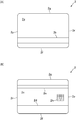
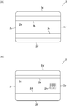
- FIG. 1 is a perspective view of a card issuing device according to an embodiment of the present invention. It is a figure for demonstrating the structure of the 1st floor part of the card issuing apparatus shown in FIG. It is a figure for demonstrating the card issued by the card issuing apparatus shown in FIG. It is a figure for demonstrating the card which can be issued with the card issuing apparatus shown in FIG. 2 is a list of cards that can be issued by the card issuing apparatus shown in FIG. It is a perspective view of the card inversion mechanism shown in FIG. It is a flowchart for demonstrating a part of operation
- FIG. 1 is a perspective view of a card issuing device 1 according to an embodiment of the present invention.
- FIG. 2 is a diagram for explaining the configuration of the first floor portion of the card issuing apparatus 1 shown in FIG.
- FIG. 3 is a diagram for explaining the card 2 issued by the card issuing apparatus 1 shown in FIG.
- FIG. 4 is a diagram for explaining a card 2 that can be issued by the card issuing apparatus 1 shown in FIG.
- FIG. 5 is a list of cards 2 that can be issued by the card issuing device 1 shown in FIG.
- FIG. 6 is a perspective view of the card transport mechanism 10 shown in FIG.
- the card issuing device 1 of this embodiment includes two card readers 3 and 4 that read data recorded on the card 2 and record data on the card 2, a printer 5 that prints an image on the card 2, a card 2, a label affixing machine (labeler) 6 for applying a label (seal), five card accommodating parts 7 for accommodating the cards 2 before issuance, and a card removing part 8 for taking out the issued cards 2
- the card collection unit 9 collects the cards 2 that are no longer needed, and the card transport mechanism 10 for transporting the cards 2 between these components. Note that the card issuing device 1 may not include the labeler 6.
- each of the three directions orthogonal to each other is defined as an X direction, a Y direction, and a Z direction.
- the Z direction is defined as the vertical direction.
- the X direction is the left-right direction
- the Y direction is the front-rear direction
- the X1 direction side of the left-right direction is the “right” side
- the opposite X2 direction side is the “left” side
- the front-rear direction The Y1 direction side is the “front” side
- the opposite Y2 direction side is the “rear” side
- the Z1 direction side of the vertical direction is the “upper” side
- the opposite side is the Z2 direction side Is the “lower” side.
- the card readers 3 and 4, the printer 5, and the labeler 6 are disposed on the front end side of the card issuing device 1.
- the card storage unit 7, the card removal unit 8, and the card collection unit 9 are disposed on the rear end side of the card issuing device 1.
- the card transport mechanism 10 is disposed at an intermediate position of the card issuing device 1 in the front-rear direction. In the front-rear direction, the card readers 3, 4, the printer 5, the labeler 6, the five card storage units 7, and the card take-out unit 8 and the card collection unit 9.
- the two card readers 3 and 4 are arranged so as to be adjacent in the left-right direction.
- the printer 5 and the labeler 6 are arranged so as to be adjacent in the left-right direction.
- the printer 5 and the labeler 6 are disposed above the card readers 3 and 4.
- Three of the five card accommodating portions 7 are arranged so as to be adjacent in the left-right direction.
- the card extraction unit 8 and the card recovery unit 9 are arranged so as to overlap in the vertical direction, and the remaining two card storage units 7, the card extraction unit 8 and the card recovery unit 9 are adjacent in the horizontal direction.
- the two card accommodating portions 7, the card extracting portion 8, and the card collecting portion 9 are disposed above the three card accommodating portions 7 that are adjacently disposed in the left-right direction.
- the card issuing device 1 has a so-called two-story structure, and the card readers 3 and 4 and the three card storage units 7 constitute the first floor portion of the card issuing device 1. (See FIG. 2).
- the printer 5, the labeler 6, the two card storage units 7, the card removal unit 8, and the card collection unit 9 constitute the second floor portion of the card issuing device 1.
- the card issuing device 1 may have a one-story structure.
- Card 2 is a substantially rectangular vinyl chloride card having a thickness of about 0.7 to 0.8 mm. As shown in FIG. 3, a magnetic stripe 2 b on which magnetic data is recorded is formed on the back surface 2 a of the card 2. On the front surface 2c of the card 2, a magnetic stripe 2d for recording magnetic data is formed.
- the magnetic stripes 2b and 2d are magnetic stripes defined by the JIS standard “JISX6302-2”. When viewed from the thickness direction of the card 2, the magnetic stripe 2b and the magnetic stripe 2d overlap.
- a magnetic stripe 2e on which magnetic data is recorded is formed on the front surface 2c of the card 2.
- the magnetic stripe 2e is formed in parallel with the magnetic stripe 2d.
- the width of the magnetic stripe 2e (width in the short direction of the card 2) is equal to the width of the magnetic stripe 2d (width in the short direction of the card 2).
- the distance between the short end direction 2f of the card 2 formed in a substantially rectangular shape and the magnetic stripe 2d is equal to the distance between the short end direction 2g of the card 2 and the magnetic stripe 2e.
- the card 2 includes an IC chip (not shown). On the front surface 2c of the card 2, external connection terminals 2h of IC chips are formed.
- the card 2 issued by the card issuing device 1 is a magnetic card on which magnetic stripes 2b, 2d, and 2e on which magnetic data is recorded are formed.
- the card 2 issued by the card issuing device 1 is also a contact type IC card in which an IC chip is built and an external connection terminal 2h is formed.
- the card issuing device 1 As shown in FIG. 4, it is possible to issue a card 2 having a magnetic stripe 2k on which magnetic data is recorded on the back surface 2a of the card 2.
- the magnetic stripe 2k is formed in parallel with the magnetic stripe 2b.
- the width of the magnetic stripe 2k (width in the short direction of the card 2) is equal to the width of the magnetic stripe 2b (width in the short direction of the card 2).
- the distance between the short end direction 2f of the card 2 and the magnetic stripe 2b is equal to the distance between the short end direction 2g of the card 2 and the magnetic stripe 2k.
- the card issuing device 1 can issue the card 2 on which the magnetic stripes 2b, 2d, 2e, and 2k are not formed. Further, the card issuing device 1 can issue the card 2 on which one, two, or three magnetic stripes arbitrarily selected from the magnetic stripes 2b, 2d, 2e, and 2k are formed. ing.
- the cards 2 that can be issued by the card issuing device 1 are summarized as shown in the list of FIG. That is, in the card issuing device 1, No. 1 in FIG. 1-No. Sixteen 16 types of cards 2 can be issued.
- JIS2-1 corresponds to the magnetic stripe 2d
- ISO-1 corresponds to the magnetic stripe 2b
- JIS2-2 corresponds to the magnetic stripe 2e
- ISO-2 corresponds to the magnetic stripe 2k
- a magnetic stripe marked with “ ⁇ ” is formed on the card 2
- a magnetic stripe marked with “x” is not formed on the card 2.
- the card 2 issued by the card issuing device 1 according to the present embodiment is the No. in the list of FIG. 8 card 2.
- the card readers 3 and 4 include a magnetic head 13 that records magnetic data on the card 2 and reads magnetic data recorded on the card 2.
- the card readers 3 and 4 of this embodiment are provided with two magnetic heads 13 arranged to face each other in the vertical direction. One of the two magnetic heads 13 is disposed so as to face the card transport path from the upper side, and the other magnetic head 13 is disposed so as to face the card transport path from the lower side.
- the two magnetic heads 13 are arranged at positions where the magnetic stripes 2b, 2d or the magnetic stripe 2e of the card 2 pass in the left-right direction.
- the card readers 3 and 4 include an IC contact block 14 having a plurality of IC contact springs (not shown) that come into contact with the external connection terminals 2 h of the card 2.
- the card reader 3 of this embodiment is a first card reader, and the card reader 4 is a second card reader.
- the card readers 3 and 4 are provided with a card 2 transport mechanism.
- the card 2 In the card readers 3 and 4, the card 2 is transported in the front-rear direction. That is, the conveyance direction of the card 2 conveyed by the card reader 3 and the conveyance direction of the card 2 conveyed by the card reader 4 are parallel.
- the issued card 2 is taken into the card readers 3 and 4 from the back side of the card readers 3 and 4 and discharged from the card readers 3 and 4 to the back side.
- the card readers 3 and 4 the card 2 is conveyed in a state where the longitudinal direction of the card 2 matches the front-rear direction and the short direction of the card 2 matches the left-right direction.
- the front-rear direction (Y direction) is the card 2 transport direction
- the vertical direction (Z direction) is the thickness direction of the card 2 being transported.
- the left-right direction (X direction) is the width direction (short width direction) of the card 2.
- the card reader 3 and the card reader 4 are configured similarly. That is, the card reader 3 and the card reader 4 are configured by arranging identical components in the same manner.
- the card reader 3 and the card reader 4 configured similarly are arranged so that the directions in the front-rear direction are opposite to each other. That is, the card reader 3 and the card reader 4 are arranged point-symmetrically with respect to the midpoint of the virtual line connecting the center of the card reader 3 and the center of the card reader 4 when viewed from the vertical direction. .
- the two magnetic heads 13 are arranged on the left rear end side of the card reader 3, and in the card reader 4, the two magnetic heads 13 are connected to the card reader 4. It is arranged on the right front end side. That is, the magnetic head 13 of the card reader 3 is disposed on one side in the left-right direction, which is the width direction of the card 2, and the magnetic head 13 of the card reader 4 is disposed on the other side in the left-right direction.
- the IC contact block 14 is disposed on the front end side of the card reader 3, and in the card reader 4, the IC contact block 14 is disposed on the rear end side of the card reader 4.
- the magnetic data recorded on the magnetic stripes 2b and 2d and the magnetic data recorded on the magnetic stripes 2b and 2d are read by the two magnetic heads 13 of the card reader 3, and the card reader 4 One of the two magnetic heads 13 reads the magnetic data recorded on the magnetic stripe 2e and records the magnetic data on the magnetic stripe 2e.
- data communication is performed between the card reader 3 and the card 2 using the IC contact block 14 of the card reader 3.
- the magnetic data recorded on the magnetic stripes 2b and 2d and the magnetic stripes can be read by the two magnetic heads 13 of the card reader 4.
- Magnetic data is recorded on 2b and 2d, and one of the two magnetic heads 13 of the card reader 3 reads the magnetic data recorded on the magnetic stripe 2e or onto the magnetic stripe 2e. Recording of magnetic data may be performed. Further, depending on the orientation of the card 2 accommodated in the card accommodating portion 7, data communication may be performed between the card reader 4 and the card 2 using the IC contact block 14 of the card reader 4.
- a card transport path is formed inside the printer 5. Further, the printer 5 includes a card 2 transport mechanism. In the printer 5, the card 2 is conveyed in the front-rear direction. In this embodiment, the issued card 2 is taken into the printer 5 from the back side of the printer 5 and discharged from the printer 5 to the back side. Further, in the printer 5, the card 2 is conveyed in a state where the longitudinal direction of the card 2 matches the front-rear direction and the short direction of the card 2 matches the left-right direction.
- the labeler 6 includes a card 2 transport mechanism.
- the card 2 is conveyed in the front-rear direction.
- the issued card 2 is taken into the labeler 6 from the back side of the labeler 6 and discharged from the labeler 6 to the back side.
- the card 2 is transported in a state where the longitudinal direction of the card 2 matches the front-rear direction and the short direction of the card 2 matches the left-right direction.
- the card taking-out part 8 and the card collecting part 9 are formed in a box shape whose upper surface is open.
- the card storage unit 7 includes a storage box in which a plurality of cards 2 before issuance are stacked and stored, and a delivery mechanism for the card 2 disposed below the storage box.
- the storage box is formed in a box shape whose upper end and rear end are open.
- the storage box accommodates the card 2 so that the longitudinal direction of the card 2 matches the front-rear direction, and the short side direction of the card 2 matches the left-right direction.
- the delivery mechanism includes, for example, a delivery claw that abuts against the rear end of the lowermost card 2 in the storage box and feeds the card 2 and a drive mechanism for the delivery claw, and is accommodated in the storage box. Send out cards 2 one by one toward the front.
- a delivery hole through which the card 2 delivered by the delivery mechanism passes is formed on the lower end side of the front side surface of the storage box.
- the card transport mechanism 10 linearly moves the carriage 17 in the left-right direction, two card holding units 15 and 16 that temporarily hold the card 2 inside, a carriage 17 on which the card holding units 15 and 16 are mounted.
- the card holding part 15 and the card holding part 16 are arranged so as to overlap in the vertical direction.
- the card holding portions 15 and 16 are rotatably held by the carriage 17. Specifically, the card holders 15 and 16 are held by the carriage 17 so that the card holders 15 and 16 can be rotated with the left-right direction as the axis direction of rotation.
- the card holding units 15 and 16 include a pull-in / out mechanism 22 that pulls in and out the card 2. Inside the card holders 15 and 16, a card transport path 27 through which the card 2 drawn or sent out by the pull-in / out mechanism 22 is formed linearly.
- the pull-out delivery mechanism 22 includes a driving roller 25, a pad roller 26 disposed opposite to the driving roller 25, a motor that rotates the driving roller 25, and a power transmission mechanism that transmits the power of the motor to the driving roller 25. ing.
- the pull-in / out mechanism 22 pulls the card 2 into the card transport path 27 and sends out the card 2 from the card transport path 27 so that the pull-in direction and the transport direction of the card 2 coincide with the longitudinal direction of the card 2. Further, the short direction of the card 2 drawn into the card transport path 27 coincides with the left-right direction.
- the guide shafts 19 and 20 are fixed to the support frame 21 so that the axial direction of the guide shafts 19 and 20 coincides with the left-right direction.
- the carriage 17 is supported by the guide shafts 19 and 20 so as to be slidable in the left-right direction.
- the carriage moving mechanism 18 includes a motor as a drive source and a power transmission mechanism that transmits the power of the motor to the carriage 17. When the motor of the carriage moving mechanism 18 rotates, the carriage 17 is guided by the guide shafts 19 and 20 and moves in the left-right direction.
- the rotation mechanism 24 includes a motor as a driving source and a power transmission mechanism that transmits the power of the motor to the card holding portions 15 and 16.
- the motor of the rotation mechanism 24 rotates, the card holding unit 15 and the card holding unit 16 rotate together in the same direction.
- the card holders 15 and 16 rotate with the left-right direction as the axis direction of rotation.
- the card holders 15 and 16 of the present embodiment are in a state where the card transport path 27 of the card holder 15 is parallel to the horizontal direction, and the card transport path 27 of the card holder 16 is parallel to the horizontal direction. Until the card transport path 27 of the card holders 15 and 16 is turned upside down, the left and right directions can be rotated 180 °.
- the front and back of the card 2 held in the card holding units 15 and 16 can be reversed.
- the card 2 held in the card holding portions 15 and 16 can be rotated with the short side direction of the card 2 being the rotation axis direction, so that the front and back of the card 2 can be reversed. It has become.
- the card transport mechanism 10 of this embodiment is a card reversing mechanism that reverses the front and back of the card 2.
- the card holders 15 and 16 are rotated to the middle position of the rotation range of the card holders 15 and 16 (that is, the card is held from the state where the card transport path 27 is parallel to the horizontal direction).
- the sections 15 and 16 are rotated by 90 °, the card 2 can be directly transferred between the card holding section 15 and the card holding section 16 in the vertical direction.
- the card transport path 27 when the card transport path 27 is parallel to the horizontal direction, the height of the card transport path of the card readers 3 and 4 and the height of the card transport path 27 of the card holding unit 16 in the vertical direction. And the height of the card conveyance path of the printer 5, the height of the card conveyance path of the labeler 6, and the height of the card conveyance path 27 of the card holding unit 15. Therefore, in a state where the card transport path 27 is parallel to the horizontal direction, the card 2 is transported between the card readers 3 and 4 and the card holding unit 16, and each of the printer 5 and the labeler 6 is held with the card. The card 2 can be transported to and from the unit 15.
- the height of the card transport path 27 of the card holding unit 15 and the upper side of the card 2 of the two card storage units 7 are arranged in the vertical direction.
- the height of the delivery hole coincides, and the height of the card transport path 27 of the card holding unit 16 and the height of the delivery hole of the card 2 of the three card accommodation units 7 arranged below coincide. . Therefore, in a state where the card transport path 27 is parallel to the horizontal direction, the card 2 sent out from the card storage unit 7 can be drawn into the card holding units 15 and 16.
- the card transport path 27 of the card holding unit 15 is disposed slightly above the bottom surface of the card removal unit 8.
- the front surface 2c of the card 2 faces upward, and one end surface 2p in the longitudinal direction of the card 2 is disposed on the front side.
- the other end surface 2r in the direction is arranged on the rear side (see FIG. 8A).
- the card reader 3 moves to the magnetic stripes 2b and 2d by the two magnetic heads 13. Normal recording of the magnetic data and normal reading of the magnetic data recorded on the magnetic stripes 2b and 2d become possible, and in the card reader 4, normal recording of the magnetic data on the magnetic stripe 2e by the magnetic head 13 is possible.
- the magnetic data recorded on the magnetic stripe 2e can be normally read.
- the card 2 in which the front surface 2c of the card 2 faces upward and the one end surface 2p in the longitudinal direction of the card 2 is arranged on the front side is taken into the card readers 3 and 4
- the magnetic data can be normally recorded on the magnetic stripes 2b and 2d by the magnetic heads 13 and the magnetic data recorded on the magnetic stripes 2b and 2d can be normally read. Normal recording of the magnetic data on the magnetic stripe 2e and normal reading of the magnetic data recorded on the magnetic stripe 2e are possible.
- the card reader 3 14 normal data communication between the card reader 3 and the card 2 becomes possible.
- a card 2 in which the front surface 2c of the card 2 faces upward and the other end surface 2r in the longitudinal direction of the card 2 is disposed on the front side is taken into the card readers 3 and 4.
- the card reader 4 can perform normal recording of magnetic data on the magnetic stripes 2b and 2d by the two magnetic heads 13 and normal reading of the magnetic data recorded on the magnetic stripes 2b and 2d.
- the magnetic head 13 can normally record the magnetic data on the magnetic stripe 2e and can normally read the magnetic data recorded on the magnetic stripe 2e.
- FIG. 7 is a flowchart for explaining a part of the operation of the card issuing apparatus 1 shown in FIG.
- FIG. 8 is a view for explaining the orientation of the card 2 accommodated in the card accommodating portion 7 shown in FIG. In FIG. 8, the external connection terminal 2h is not shown.
- the card issuing device 1 When a card 2 issuance command is input to the card issuing device 1 from a higher-level device such as a personal computer to which the card issuing device 1 is connected, the card issuing device 1 sends a card to the card readers 3 and 4 before issuing the card 2. 2 is executed to execute the determination process for determining the orientation of the card 2, and the card 2 issuance process is executed based on the result of the determination process. Specifically, as shown in FIG. 7, when an issuance command for a card 2 is input to the card issuing device 1, the card issuing device 1 first stores the card 2 sent out from the card storage unit 7 as the first card. The data is taken into the card reader 3 which is a reader, and magnetic data is recorded on and read from the card 2 (step S1).
- step S1 the card transport mechanism 10 transports the card 2 sent out from the card storage unit 7 to the card reader 3, and the card reader 3 takes in the transported card 2.
- the orientation of the card 2 taken into the card reader 3 matches the orientation of the card 2 when accommodated in the card accommodation portion 7.
- step S ⁇ b> 1 the card reader 3 records and reads magnetic data with respect to the card 2 by the two magnetic heads 13 of the card reader 3 while conveying the card 2. Specifically, the card reader 3 records the magnetic data on the card 2 with the two magnetic heads 13 and then reads the magnetic data. Thereafter, the card issuing device 1 determines whether or not the magnetic data can be normally read by the two magnetic heads 13 in step S1 (step S2).
- step S1 when the card 2 accommodated in the card accommodating portion 7 in the correct orientation is taken into the card reader 3 in the same orientation, the magnetic data on the card 2 by the two magnetic heads 13 is read by the card reader 3. Normal recording and normal reading of the magnetic data recorded on the card 2 become possible. Therefore, when the card 2 sent out from the card accommodating part 7 is accommodated in the card accommodating part 7 in the correct orientation (when the card 2 is accommodated in the card accommodating part 7 in the direction shown in FIG. 8A). In step S1, appropriate magnetic data can be recorded in the magnetic stripes 2b and 2d, and as a result, the magnetic data can be read normally.
- the magnetic stripe 2b formed by the two magnetic heads 13 in the card reader 3 is used.
- normal recording of the magnetic data on 2d and normal reading of the magnetic data recorded on the magnetic stripes 2b and 2d become possible.
- the magnetic data on the magnetic stripe 2e by the magnetic head 13 is normal. Recording and normal reading of magnetic data recorded on the magnetic stripe 2e are possible, and the card reader 3 can communicate normal data between the card reader 3 and the card 2 using the IC contact block 14. become.
- step S2 if it is determined in step S2 that the magnetic data can be normally read by the two magnetic heads 13 (that is, if “Yes” in step S2), the card issuing device 1 After erasing the magnetic data recorded on the card 2 in S1, the issuing process of the card 2 is started.
- the card 2 sent out from the card storage unit 7 has the front / back and front / rear orientations of the card 2 with respect to the correct orientation of the card 2 stored in the card storage unit 7.
- the card is housed in the card housing portion 7 in the opposite state (the front and back of the card 2 are reversed and the other end surface 2r of the card 2 is disposed on the front side), and the card housing portion 7
- the card 2 sent out from the card 2 is in a state where the front and back sides and the left and right directions of the card 2 are opposite to the correct orientation of the card 2 stored in the card storage unit 7.
- the card 2 sent out from the card storage unit 7 has the front and rear and left and right directions of the card 2 with respect to the correct orientation of the card 2 stored in the card storage unit 7.
- the card is stored in the card storage unit 7 in the opposite state, one of the two magnetic heads 13 of the card reader 3 cannot properly record magnetic data in step S1. As a result, the magnetic data cannot be read normally.
- step S2 when it is determined in step S2 that the magnetic data cannot be normally read by at least one magnetic head 13 (that is, in the case of “No” in step S2), the card issuing device 1
- the card 2 is discharged from the card reader 3, and the card transport mechanism 10 reverses the front and back of the card 2 (step S3).
- the card issuing device 1 rotates the card 2 with the short direction of the card 2 being the axial direction of rotation, and reverses the front and back of the card 2.
- the card issuing device 1 takes the card 2 with the front and back reversed into the card reader 3 again, and records and reads the magnetic data on the card 2 (step S4).
- the card reader 3 records the magnetic data on the card 2 by the two magnetic heads 13 of the card reader 3 while transporting the card 2, and then reads the magnetic data.
- the card issuing device 1 determines whether or not the magnetic data can be normally read by the two magnetic heads 13 in step S4 (step S5).
- step S4 the card 2 is in the direction shown in FIG. 8A. Captured by the reader 3.
- the card reader 3 performs normal recording of magnetic data on the magnetic stripes 2b and 2d by the two magnetic heads 13.
- the magnetic data recorded on the magnetic stripes 2b and 2d can be normally read.
- the magnetic data is normally recorded on the magnetic stripe 2e by the magnetic head 13 and the magnetic data recorded on the magnetic stripe 2e. Data can be read normally, and in the card reader 3, normal data communication between the card reader 3 and the card 2 using the IC contact block 14 becomes possible.
- step S5 when it is determined in step S5 that the magnetic data can be normally read by the two magnetic heads 13 (that is, in the case of “Yes” in step S5), the card issuing device 1 After erasing the magnetic data recorded on the card 2 in S5, the card 2 issuing process is started.
- step S5 determines whether the magnetic data cannot be normally read by at least one magnetic head 13 (that is, if “No” in step S5)
- the card issuing device 1 The card 2 is discharged from the card reader 3, and the card transport mechanism 10 reverses the front and back of the card 2 (step S6).
- step S ⁇ b> 6 the card issuing device 1 rotates the card 2 with the short side direction of the card 2 being the axial direction of rotation, and reverses the front and back of the card 2.
- the card issuing device 1 takes the card 2 with the front and back reversed into the card reader 4 as the second card reader, and records and reads the magnetic data on the card 2 (step S7).
- the card transport mechanism 10 transports to the card reader 4, and the card reader 4 takes in the transported card 2.
- the card reader 4 records the magnetic data on the card 2 by the two magnetic heads 13 of the card reader 4 while transporting the card 2, and then reads the magnetic data.
- the card issuing device 1 determines whether or not the magnetic data can be normally read by the two magnetic heads 13 in step S7 (step S8).
- step S7 the card 2 is in the direction shown in FIG. 8C. Captured by the reader 4.
- step S7 the magnetic data is appropriately recorded on the magnetic stripes 2b and 2d by the two magnetic heads 13. As a result, the magnetic data can be read normally.
- the magnetic data on the magnetic stripes 2b and 2d by the two magnetic heads 13 in the card reader 4 is normal. Recording and normal reading of the magnetic data recorded on the magnetic stripes 2b and 2d becomes possible, and the card reader 3 allows the magnetic head 13 to normally record the magnetic data on the magnetic stripe 2e and to record on the magnetic stripe 2e. Thus, normal reading of the magnetic data can be performed, and in the card reader 4, normal data communication between the card reader 4 and the card 2 using the IC contact block 14 becomes possible.
- step S8 when it is determined in step S8 that the magnetic data can be normally read by the two magnetic heads 13 (that is, in the case of “Yes” in step S8), the card issuing device 1 It is stored that the front / rear and left / right orientations of the card 2 on which the discrimination processing is being performed are opposite to the correct orientation of the card 2 accommodated in the card accommodating portion 7 (step S9), and step S7. After erasing the magnetic data recorded on the card 2, the card 2 issuance process is started.
- step S8 determines whether the magnetic data cannot be normally read by at least one magnetic head 13 (that is, if “No” in step S8)
- the card issuing device 1 The card 2 is discharged from the card reader 4, and the card transport mechanism 10 reverses the front and back of the card 2 (step S10). Specifically, in step S10, the card issuing device 1 rotates the card 2 with the short side direction of the card 2 being the axial direction of rotation, and reverses the front and back of the card 2.
- the card issuing device 1 takes the card 2 with the front and back reversed into the card reader 4 and records and reads the magnetic data on the card 2 (step S11).
- the card reader 4 records the magnetic data on the card 2 by the two magnetic heads 13 of the card reader 4 while carrying the card 2, and then reads the magnetic data.
- the card issuing device 1 determines whether or not the magnetic data can be normally read by the two magnetic heads 13 in step S11 (step S12).
- step S11 When the card 2 sent out from the card accommodating portion 7 is accommodated in the card accommodating portion 7 in the direction shown in FIG. 8D, in step S11, the card 2 is in the orientation shown in FIG. 8C. Captured by the reader 3. Therefore, when it is determined in step S12 that the magnetic data can be normally read by the two magnetic heads 13 (that is, in the case of “Yes” in step S12), the process proceeds to step S9 and the card The issuing device 1 stores the fact that the front and rear and left and right orientations of the card 2 that is currently being discriminated are opposite to the correct orientation of the card 2 that is accommodated in the card accommodating portion 7, and After erasing the magnetic data recorded on the card 2 in step S11, the card 2 issuing process is started.
- step S12 if it is determined in step S12 that the magnetic data cannot be normally read by at least one magnetic head 13 (that is, if “No” in step S12), the card issuing device 1 It is determined that there is some abnormality in the card 2 sent out from the card accommodation unit 7, and card abnormality processing is executed. For example, the card issuing device 1 abnormally stops. Alternatively, the card issuing device 1 collects the card 2 in the card collection unit 9, sends out a new card 2 from the card storage unit 7, and returns to step S1.
- the card 2 is first taken into the card reader 3 in the same direction.
- the card reader 3 performs recording of the magnetic data on the magnetic stripes 2b and 2d and reading of the magnetic data for confirming the recorded magnetic data. Further, the card reader 3 performs data communication with the card 2 using the IC contact block 14. Thereafter, the card 2 is ejected from the card reader 3 and is transported to the card transport mechanism 10 and then taken into the card reader 4 as it is.
- the card reader 4 performs recording of magnetic data on the magnetic stripe 2e and reading of magnetic data for confirming the recorded magnetic data.
- the card 2 Is taken in the card reader 4 in the same direction.
- the card reader 4 performs recording of the magnetic data on the magnetic stripes 2b and 2d and reading of the magnetic data for confirming the recorded magnetic data. Further, the card reader 4 performs data communication with the card 2 using the IC contact block 14. Thereafter, the card 2 is ejected from the card reader 4 and is transported to the card transport mechanism 10 and then taken into the card reader 3 as it is.
- the card reader 3 performs recording of magnetic data on the magnetic stripe 2e and reading of magnetic data for confirming the recorded magnetic data.
- the magnetic data may not be recorded on the magnetic stripes 2b and 2d, or the magnetic data may not be recorded on the magnetic stripe 2e.
- data communication using the IC contact block 14 may not be performed between the card reader 3 or the card reader 4 and the card 2.
- the card 2 that has been processed by the card readers 3 and 4 is transferred to the card transfer mechanism 10 and then taken into the printer 5.
- the printer 5 prints an image on the card 2.
- the printer 5 determines the orientation of the image printed on the card 2 in accordance with the orientation of the card 2 captured by the printer 5. Specifically, when the card 2 in which the front surface 2c of the card 2 faces upward and the one end surface 2p in the longitudinal direction of the card 2 is arranged on the front side is taken into the printer 5 (“Yes” in step S2). If the result is “Yes” and “Yes” in step S5), the printer 5 prints an image in the normal orientation on the card 2.
- step S8 when the card 2 having the front surface 2c of the card 2 facing upward and the other end surface 2r in the longitudinal direction of the card 2 disposed on the front side is taken into the printer 5 (“Yes” in step S8). In this case, and when “Yes” is determined in step S12), the printer 5 prints an image rotated 180 ° from the normal direction on the card 2.
- the card 2 is ejected from the printer 5 and conveyed to the card conveying mechanism 10 and then taken into the labeler 6.
- the labeler 6 attaches a label to the card 2.
- the card 2 is ejected from the labeler 6 and conveyed to the card extraction unit 8 by the card conveying mechanism 10. Further, when the card 2 is ejected to the card removal unit 8, the card 2 issuance process is completed. In the card 2 issuing process, an image may not be printed on the card 2 and a label may not be attached to the card 2.
- Step S1 in this embodiment is a first recording step in which the card 2 sent out from the card storage unit 7 is taken into the card reader 3 and recording and reading of magnetic data with respect to the card 2 are performed.
- Step S3 is step S1.
- This is a card reversal step in which when the magnetic data cannot be read normally, the card 2 is ejected from the card reader 3 and the front and back of the card 2 are reversed.
- Step S4 is a card reversal step after the step S3. And a second recording / reading step for recording and reading magnetic data on the card 2.
- step S7 when the magnetic data cannot be normally read in step S4, the card 2 ejected from the card reader 3 is taken into the card reader 4 and the magnetic data is recorded and read on the card 2.
- step S6 is a second card reversing step for discharging the card 2 from the card reader 3 and reversing the front and back of the card 2 before step S7.
- step S10 is a third card reversal step in which the card 2 is ejected from the card reader 4 and the front and back of the card 2 are reversed when the magnetic data cannot be normally read in step S7.
- This is a fourth recording / reading step in which the card 2 is taken into the card reader 4 after step S10 and magnetic data is recorded on and read from the card 2.
- steps S1 to S12 of this embodiment are card orientation determination steps for executing a discrimination process for taking the card 2 into the card readers 3 and 4 and discriminating the orientation of the card 2 before issuing the card 2. .
- the card orientation determination step recording and reading of magnetic data with respect to the card 2 are performed by the card readers 3 and 4, and the orientation of the card 2 is determined based on the reading result of the magnetic data. Specifically, in the card orientation determination step, it is determined which orientation shown in FIGS. 8A to 8D is the orientation of the card 2 accommodated in the card accommodating portion 7.
- the step of executing the card 2 issuing process is a card issuing step of executing the card 2 issuing process based on the result of the determination process in the card orientation determining step.
- the control method of the card issuing device 1 includes the card orientation determining step and the card issuing step.
- the step in which the printer 5 prints an image on the card 2 is a printing step.
- the printing step the card 2 is loaded on the card 2 based on the result of the discrimination processing in the card orientation discrimination step. The orientation of the image to be printed is determined.
- step S1 the card 2 sent out from the card storage unit 7 is taken into the card reader 3 to record and read the magnetic data on the card 2, and the magnetic data cannot be read normally in step S1.
- step S4 the card 2 with the front and back reversed is taken into the card reader 3 to record and read magnetic data from the card 2. Therefore, in this embodiment, it is possible to determine the front / back orientation of the card 2. Therefore, in this embodiment, even if the card 2 is stored in the card storage unit 7 with the card 2 facing in the wrong direction, the card 2 is issued by appropriately recording magnetic data or the like on the card 2. Is possible.
- the two magnetic heads 13 of the card reader 3 are arranged on the left rear end side of the card reader 3, and the two magnetic heads 13 of the card reader 4 are on the right front end side of the card reader 4. If the magnetic data cannot be normally read in step S4, the card 2 is taken into the card reader 4 and the magnetic data is recorded and read in the card 2 in step S7. Therefore, in this embodiment, it is possible to determine the front-rear direction of the card 2. Therefore, in this embodiment, even when the card 2 is stored in the card storage unit 7 in a state where the front and rear directions of the card 2 are wrong, the card 2 is issued by appropriately recording magnetic data or the like on the card 2. Is possible.
- the card 2 is stored in the card storage unit 7 in a state where the front and back of the card 2 and the front and back directions are opposite to the correct direction of the card 2 stored in the card storage unit 7.
- the card 2 is stored in the card storage portion 7 in a state where the front and rear and left and right directions of the card 2 are opposite to the correct orientation of the card 2 stored in the card storage portion 7,
- the card 2 It is possible to issue the card 2 by appropriately recording magnetic data or the like.
- the card 2 with the front and back reversed is taken into the card reader 4 in step S11, and the magnetic data is recorded and read on the card 2. If there is any abnormality in the card 2 sent out from the card storage unit 7, the magnetic data cannot be normally read even in step S11. For this reason, in this embodiment, it is possible to determine whether or not there is any abnormality in the card 2 sent out from the card storage unit 7 based on the magnetic data read result in step S11. For example, it is possible to determine whether or not the card 2 sent out from the card storage unit 7 is a different type of card 2 from the card 2 to be issued. Alternatively, it is possible to determine whether or not the card 2 sent out from the card storage unit 7 is damaged.
- the printer 5 determines the orientation of the image printed on the card 2 according to the orientation of the card 2 taken into the printer 5 and prints the image on the card 2. Therefore, in this embodiment, even if the card 2 is stored in the card storage unit 7 in a state where the front and rear directions of the card 2 are wrong, it is possible to print an appropriate image on the card 2 using the common printer 5. become.
- the card 2 issued by the card issuing device 1 is the No. in the list of FIG. 8, other cards 2 in the list of FIG. 5 may be issued by the card issuing device 1.
- Cards 2 (No. 2 to No. 4, No. 7, No. 10, No. 12, No. 14, No. 15 cards 2) grouped into “Group 1” in the list of FIG.
- the card issuing device 1 executes the same card orientation determination steps S1 to S12 as those described above before issuing the card 2, for example, to change the orientation of the card 2. Determine.
- the card issuing device 1 performs recording and reading of magnetic data on the card 2 with one magnetic head 13 in step S 1 and the like.
- the card issuing device 1 issues any of the cards 2 (No. 5, No. 9, No. 13 cards 2) grouped into “Group 2” in the list of FIG.
- the card issuing device 1 executes card orientation determining steps S1 to S12 that are substantially the same as those described above to determine the orientation of the card 2.
- the card issuing device 1 takes in the card reader 4 in steps S1 and S4 to record and read magnetic data on the card 2, and takes in the card reader 3 in steps S7 and S11. Recording and reading of magnetic data with respect to the card 2 are performed.
- the card reader 3 is a second card reader
- the card reader 4 is a first card reader.
- the card issuing device 1 records and reads the magnetic data with respect to the card 2 by one magnetic head 13 in step S 1 and the like.
- the card issuing device 1 issues any of the cards 2 (No. 6, No. 11, No. 16 cards 2) grouped into “Group 3” in the list of FIG. Although it is possible to determine the front / back orientation of the card 2, it is not possible to determine the front / rear direction of the card 2. Therefore, in this case, for example, before issuing the card 2, the card issuing device 1 executes a card orientation determining step including steps S1 to S5 to determine the orientation of the card 2. In this case, if “No” in the step S5, the card issuing device 1 executes a card abnormality process. In this case, depending on the type of the card 2, the card issuing device 1 records and reads the magnetic data with respect to the card 2 by one magnetic head 13 in step S 1 and the like.
- the card issuing device 1 issues cards 2 (No. 1 cards 2) that are grouped into “group 0” in the list of FIG. 5, the front and back direction of the card 2 and the card 2 In this case, the card issuing device 1 starts the card 2 issuing process without executing the card orientation determining step.
- the card issuing device 1 has different Nos.
- a plurality of types of cards 2 may be issued.
- the same type of card 2 is accommodated in each card accommodating portion 7.
- the card 2 issuance command is issued from the host device in accordance with the No. of the issued card 2.
- the card issuing device 1 includes the No. of the card 2 included in the card 2 issue command.
- the card 2 is sent out from the card accommodating portion 7 corresponding to the card 2 and the card 2 No.
- a card orientation determination step corresponding to the card is executed.
- step S2 when the magnetic data cannot be normally read in step S1 (that is, “No” in step S2), the card issuing device 1 ejects the card 2 from the card reader 3 and the card.
- a sixth recording / reading step may be executed in which the reader 4 captures and reads / writes magnetic data from / to the card 2.
- the front and rear direction of the card 2 can be determined. Therefore, even if the card 2 is stored in the card storage unit 7 in a state where the front and rear directions of the card 2 are wrong, it is possible to appropriately record magnetic data or the like on the card 2 and issue the card 2. .
- the card issuing device 1 ejects the card 2 from the card reader 4 and the card transport mechanism 10 reverses the front and back of the card 2.
- a four-card reversing step and a seventh recording / reading step in which the card 2 is taken into the card reader 3 or the card reader 4 after the fourth card reversing step to record and read magnetic data on the card 2 may be executed.
- the front / back orientation of the card 2 can also be determined.
- the card 2 is accommodated in the card accommodating portion 7 in a state where the front and back of the card 2 and the front and back directions are opposite to the correct orientation of the card 2 accommodated in the card accommodating portion 7.
- the card 2 is stored in the card storage unit 7 in a state where the front and rear and left and right directions of the card 2 are opposite to the correct direction of the card 2 stored in the card storage unit 7.
- the card 2 can be issued by appropriately recording magnetic data or the like on the card 2.
- the card orientation determining step recording and reading of magnetic data with respect to the card 2 are performed by the card readers 3 and 4, and the orientation of the card 2 is determined based on the reading result of the magnetic data.
- the card 2 activation process may be performed by the card reader 1 and the card 2 orientation may be determined based on the result of the activation process.
- the card issuing device 1 performs the activation process of the card 2 by bringing the IC contact into contact with the card 2 taken into the card reader 3, and in steps S7 and S11, the card reader 4
- the IC contact may be brought into contact with the card 2 taken in to perform the activation process of the card 2, and it may be determined whether or not the card 2 is activated in steps S2, S5, S8, and S12.
- the magnetic stripes 2b, 2d, and 2e may not be formed on the card 2. That is, the card 2 may not be a magnetic card.
- the card issuing device 1 performs recording and reading of magnetic data on the card 2 and activation processing of the card 2 by the card readers 3 and 4 and reading results and activation processing of the magnetic data.
- the orientation of the card 2 may be discriminated based on the result. That is, the card issuing device 1 may determine the orientation of the card 2 based on the combination of the magnetic data reading result and the activation processing result in the card orientation determining step.
- the card reader 3 includes a scanner 30 (see a two-dot chain line in FIG. 2) that acquires an image of the card 2, the card issuing device 1
- the image may be acquired by the card reader 3 and the orientation of the card 2 may be determined based on the acquired image.
- the orientation of the card 2 can be determined only by acquiring the image of the card 2 once.
- the card 2 may not be a magnetic card and may not be an IC card.
- the card issuing device 1 ends the determination of the orientation of the card 2 and proceeds to the card 2 issuing process when the magnetic data is normally read. However, if the magnetic data cannot be read normally, the card issuing device 1 may end the determination of the orientation of the card 2 according to the magnetic data reading status and proceed to the card 2 issuing process.
- step S 1 one of the two magnetic heads 13 of the card reader 3 cannot normally read magnetic data, but the other magnetic head 13 does not read magnetic data normally. If it is possible, it is assumed that the card 2 is accommodated in the card accommodating portion 7 in the state shown in FIG. 8C. In this case, the process may proceed to step S9. Further, for example, if “No” in step S8, it is assumed that the card 2 is accommodated in the card accommodating portion 7 in the state shown in FIG. 8D. In this case, step S10 is performed. After execution, the process may proceed to step S9. If “No” in step S8, the card issuing device 1 stores the fact that the front and back directions of the card 2 are correct but the front and back directions of the card 2 are opposite, and starts the card 2 issuing process. May be.
- the card issuing device 1 may not include the card reader 3 or the card reader 4.
- the card abnormality process may be executed when “No” in step S5. Even in this case, it is possible to determine the front and back direction of the card 2.
- the card conveyance mechanism 10 does not need to be provided with the function to reverse the front and back of the card 2. Even in this case, the front-rear direction of the card 2 can be determined.
- step S5 the process may proceed to step S7 without inverting the front and back of the card 2.
- the card transport mechanism 10 reverses the front and back of the card 2, but the card issuing device 1 includes a card reversing mechanism that reverses the front and back of the card 2 separately from the card transport mechanism 10. May be.
- the card reader 3 and the card reader 4 are comprised similarly, the structure of the card reader 3 and the structure of the card reader 4 may differ.
- the number of the card accommodating units 7 included in the card issuing device 1 may be four or less, or may be six or more. Moreover, in the form mentioned above, the card issuing apparatus 1 may be provided with three or more card readers.
- the card 2 may not include an IC chip.
- the card 2 may be a PET (polyethylene terephthalate) card having a thickness of about 0.18 to 0.36 mm or a predetermined thickness. It may be a paper card.
Landscapes
- Engineering & Computer Science (AREA)
- Physics & Mathematics (AREA)
- General Physics & Mathematics (AREA)
- Theoretical Computer Science (AREA)
- Artificial Intelligence (AREA)
- Computer Vision & Pattern Recognition (AREA)
- Conveying Record Carriers (AREA)
- Control Of Vending Devices And Auxiliary Devices For Vending Devices (AREA)
Abstract
カード収容部に誤った向きでカードが収容されていてもカードを発行することが可能となるカード発行装置の制御方法を提供する。発行前のカードが収容されるカード収容部と、カードに記録されたデータの読取りおよびカードへのデータの記録の少なくともいずれか一方を行うカードリーダとを備えるカード発行装置の制御方法は、カードの発行前にカードリーダにカードを取り込んでカードの向きを判別するための判別処理を実行するカード向き判別ステップS1~S12と、カード向き判別ステップS1~S12での判別処理の結果に基づいてカードの発行処理を実行するカード発行ステップとを備えている。
Description
本発明は、カードを発行するカード発行装置の制御方法に関する。また、本発明は、カードを発行するカード発行装置に関する。
従来、カードを発行するカード発行装置が知られている(たとえば、特許文献1参照)。特許文献1に記載のカード発行装置は、カードに記録されたデータの読取りやカードへのデータの記録を行う2台のカードリーダと、カードへの印字を行うプリンタと、カードにラベルを貼り付けるラベル貼付機と、発行前のカードが収容される5個のカード収容部と、発行されるカードを取り出すためのカード取出部と、不要になったカードが回収されるカード回収部と、これらの構成の間でカードを搬送するためのカード搬送機構とを備えている。このカード発行装置では、カード収容部から搬出されたカードにカードリーダでデータが記録されたり、プリンタで印字が行われたりした後に、カード取出部までカードが搬送されて、カードが発行される。
特許文献1に記載のカード発行装置では、2台のカードリーダは、隣り合うように配置されており、2台のカードリーダのうちの一方のカードリーダで搬送されるカードの搬送方向と、他方のカードリーダで搬送されるカードの搬送方向とが平行になっている。また、2台のカードリーダのうちの一方のカードリーダでは、カードリーダ内で搬送されるカードの幅方向の一方側に磁気ヘッドが配置され、他方のカードリーダでは、カードリーダ内で搬送されるカードの幅方向の他方側に磁気ヘッドが配置されている。
また、特許文献1に記載のカード発行装置で使用されるカードには、磁気データが記録される磁気ストライプが形成されている。具体的には、図3に示すように、カード2の裏面2aに磁気ストライプ2bが形成され、カード2のおもて面2cに2本の磁気ストライプ2d、2eが形成されている。特許文献1に記載のカード発行装置では、2台のカードリーダのうちの一方のカードリーダの磁気ヘッドによって、磁気ストライプ2b、2dへの磁気データの記録や磁気ストライプ2b、2dに記録された磁気データの読取りが行われ、他方のカードリーダの磁気ヘッドによって、磁気ストライプ2eへの磁気データの記録や磁気ストライプ2eに記録された磁気データの読取りが行われている。
特許文献1に記載のカード発行装置では、作業員のミス等によってカード収容部に誤った向きでカードが収容される場合が生じうる。たとえば、カード収容部に収容されるカードの正しい向きに対して、カードの前後の向きが反対になった状態でカード収容部にカードが収容される場合が生じうる。特許文献1に記載のカード発行装置は、カード収容部に正しい向きでカードが収容されていることを前提として、カードの発行処理を行う。そのため、このカード発行装置において、誤った向きでカード収容部に収容されているカードの発行動作が行われると、カードの発行処理中に、たとえば、カードリーダでのデータの記録エラー等の異常が発生する。
特許文献1に記載のカード発行装置では、カードリーダでのデータの記録エラー等の異常がカードの発行処理中に発生すると、たとえば、異常が発生したカードはカード回収部に廃棄され、その後、カードの発行処理が異常終了するか、あるいは、新たなカードを使用したカードの再発行処理が行われる。すなわち、このカード発行装置では、誤った向きでカード収容部に収容されたカードを発行することはできない。
そこで、本発明の課題は、カード収容部に誤った向きでカードが収容されていてもカードを発行することが可能となるカード発行装置の制御方法を提供することにある。また、本発明の課題は、カード収容部に誤った向きでカードが収容されていてもカードを発行することが可能なカード発行装置を提供することにある。
上記の課題を解決するため、本発明のカード発行装置の制御方法は、発行前のカードが収容されるカード収容部と、カードに記録されたデータの読取りおよびカードへのデータの記録の少なくともいずれか一方を行うカードリーダとを備えるカード発行装置の制御方法であって、カードの発行前にカードリーダにカードを取り込んでカードの向きを判別するための判別処理を実行するカード向き判別ステップと、カード向き判別ステップでの判別処理の結果に基づいてカードの発行処理を実行するカード発行ステップとを備えることを特徴とする。
本発明のカード発行装置の制御方法では、カード向き判別ステップにおいて、カードの発行前にカードリーダにカードを取り込んでカードの向きを判別するための判別処理を実行し、カード向き判別ステップ後のカード発行ステップにおいて、カード向き判別ステップでの判別処理の結果に基づいてカードの発行処理を実行している。そのため、本発明では、カード収容部に収容されたカードの向きに応じたカードの適切な発行処理を行うことが可能になる。したがって、本発明では、カード収容部に誤った向きでカードが収容されていてもカードを発行することが可能になる。
本発明において、たとえば、カードは、磁気データが記録される磁気ストライプが形成された磁気カードであり、カードリーダは、カードへの磁気データの記録とカードに記録された磁気データの読取りとを行う磁気ヘッドを備え、カード向き判別ステップでは、カードに対する磁気データの記録と読取りとをカードリーダで行うとともに、磁気データの読取り結果に基づいてカードの向きを判別する。
本発明において、カード発行装置は、カードの表裏を反転させるカード反転機構を備え、カード向き判別ステップは、カード収容部から送り出されたカードをカードリーダに取り込んでカードに対する磁気データの記録と読取りを行う第1記録読取りステップと、第1記録読取りステップで磁気データの正常な読取りができなかった場合に、カードリーダからカードを排出してカード反転機構でカードの表裏を反転させるカード反転ステップと、カード反転ステップ後にカードをカードリーダに取り込んでカードに対する磁気データの記録と読取りを行う第2記録読取りステップとを備えることが好ましい。このように構成すると、カードの表裏の向きを判別することが可能になる。したがって、カードの表裏の向きが誤った状態でカード収容部にカードが収容されていても、適切なカードの発行処理を行ってカードを発行することが可能になる。
また、この場合には、カード発行装置は、カードリーダとして、第1カードリーダと第2カードリーダとを備え、第1カードリーダで搬送されるカードの搬送方向と、第2カードリーダで搬送されるカードの搬送方向とが平行になっており、カードの搬送方向と搬送されるカードの厚さ方向とに直交する方向をカードの幅方向とすると、第1カードリーダおよび第2カードリーダには、発行されるカードがカードの搬送方向の一方側から取り込まれ、第1カードリーダの磁気ヘッドは、カードの幅方向の一方側に配置され、第2カードリーダの磁気ヘッドは、カードの幅方向の他方側に配置され、第1記録読取りステップおよび第2記録読取りステップでは、第1カードリーダにカードが取り込まれ、カード向き判別ステップは、第2記録読取りステップで磁気データの正常な読取りができなかった場合に、第1カードリーダから排出されたカードを第2カードリーダに取り込んでカードに対する磁気データの記録と読取りを行う第3記録読取りステップを備えることが好ましい。
このように構成すると、カードの前後の向きも判別することが可能になる。すなわち、このように構成すると、カードの表裏の向きおよびカードの前後の向きを判別することが可能になる。したがって、カードの表裏の向きが誤った状態でカード収容部にカードが収容されていても、また、カードの前後の向きが誤った状態でカード収容部にカードが収容されていても、適切なカードの発行処理を行ってカードを発行することが可能になる。
本発明において、カード向き判別ステップは、たとえば、第3記録読取りステップの前に第1カードリーダからカードを排出してカード反転機構でカードの表裏を反転させる第2カード反転ステップを備え、第2記録読取りステップで磁気データの正常な読取りができなかった場合に、第2カード反転ステップを実行し、第2カード反転ステップ後に第3記録読取りステップを実行する。
本発明において、カード向き判別ステップは、第3記録読取りステップで磁気データの正常な読取りができなかった場合に、第2カードリーダからカードを排出してカード反転機構でカードの表裏を反転させる第3カード反転ステップと、第3カード反転ステップ後にカードを第2カードリーダに取り込んでカードに対する磁気データの記録と読取りを行う第4記録読取りステップとを備えることが好ましい。このように構成すると、カード収容部から送り出されたカードに何らかの異常があれば、第4記録読取りステップにおいても磁気データの正常な読取りができない。したがって、第4記録読取りステップでの磁気データの読取り結果に基づいて、カード収容部から送り出されたカードに何らかの異常があるのか否かを判別することが可能になる。
本発明において、カード発行装置は、カードリーダとして、第1カードリーダと第2カードリーダとを備え、第1カードリーダで搬送されるカードの搬送方向と、第2カードリーダで搬送されるカードの搬送方向とが平行になっており、カードの搬送方向と搬送されるカードの厚さ方向とに直交する方向をカードの幅方向とすると、第1カードリーダおよび第2カードリーダには、発行されるカードがカードの搬送方向の一方側から取り込まれ、第1カードリーダの磁気ヘッドは、カードの幅方向の一方側に配置され、第2カードリーダの磁気ヘッドは、カードの幅方向の他方側に配置され、カード向き判別ステップは、カード収容部から送り出されたカードを第1カードリーダに取り込んでカードに対する磁気データの記録と読取りを行う第5記録読取りステップと、第5記録読取りステップで磁気データの正常な読取りができなかった場合に、カードを第1カードリーダから排出するとともに第2カードリーダに取り込んでカードに対する磁気データの記録と読取りを行う第6記録読取りステップとを備えていても良い。この場合には、カードの前後の向きを判別することが可能になる。したがって、カードの前後の向きが誤った状態でカード収容部にカードが収容されていても、適切なカードの発行処理を行ってカードを発行することが可能になる。
また、この場合には、カード発行装置は、カードの表裏を反転させるカード反転機構を備え、カード向き判別ステップは、第6記録読取りステップで磁気データの正常な読取りができなかった場合に、第2カードリーダからカードを排出してカード反転機構でカードの表裏を反転させる第4カード反転ステップと、第4カード反転ステップ後にカードを第1カードリーダまたは第2カードリーダに取り込んでカードに対する磁気データの記録と読取りを行う第7記録読取りステップとを備えることが好ましい。
このように構成すると、カードの表裏の向きも判別することが可能になる。すなわち、このように構成すると、カードの前後の向きおよびカードの表裏の向きを判別することが可能になる。したがって、カードの前後の向きが誤った状態でカード収容部にカードが収容されていても、また、カードの表裏の向きが誤った状態でカード収容部にカードが収容されていても、適切なカードの発行処理を行ってカードを発行することが可能になる。
本発明において、カード発行装置は、カードに画像を印刷するプリンタを備え、カード発行ステップは、プリンタでカードに画像を印刷する印刷ステップを備え、印刷ステップでは、カード向き判別ステップでの判別処理の結果に基づいて、カードに印刷される画像の向きが決定されることが好ましい。このように構成すると、カードの前後の向きが誤った状態でカード収容部にカードが収容されていても、共通のプリンタを用いてカードに適切な画像を印刷することが可能になる。
本発明において、カードは、ICチップが内蔵されるとともにICチップの外部接続端子が形成されたICカードであり、カードリーダは、外部接続端子に接触する複数のIC接点バネを有するIC接点ブロックを備え、カード向き判別ステップでは、カードの活性化処理をカードリーダで行うとともに、活性化処理の結果に基づいてカードの向きを判別しても良い。
また、本発明において、カードは、磁気データが記録される磁気ストライプが形成された磁気カードであるとともに、ICチップが内蔵されかつICチップの外部接続端子が形成されたICカードであり、カードリーダは、カードへの磁気データの記録とカードに記録された磁気データの読取りとを行う磁気ヘッドと、外部接続端子に接触する複数のIC接点バネを有するIC接点ブロックとを備え、カード向き判別ステップでは、カードに対する磁気データの記録および読取りとカードの活性化処理とをカードリーダで行うとともに、磁気データの読取り結果および活性化処理の結果に基づいてカードの向きを判別しても良い。
さらに、本発明において、カードリーダは、カードの画像を取得するスキャナを備え、カード向き判別ステップでは、カードの画像をカードリーダで取得するとともに、取得した画像に基づいてカードの向きを判別しても良い。この場合には、カードの画像を1回取得するだけでカードの向きを判別することが可能になる。
また、上記の課題を解決するため、本発明のカード発行装置は、発行前のカードが収容されるカード収容部と、カードに記録されたデータの読取りおよびカードへのデータの記録の少なくともいずれか一方を行うカードリーダとを備え、カードの発行前にカードリーダにカードを取り込んでカードの向きを判別するための判別処理を実行し、判別処理の結果に基づいてカードの発行処理を実行することを特徴とする。
本発明のカード発行装置は、カードの発行前にカードリーダにカードを取り込んでカードの向きを判別するための判別処理を実行し、判別処理の結果に基づいてカードの発行処理を実行している。そのため、本発明では、カード収容部に収容されたカードの向きに応じたカードの適切な発行処理を行うことが可能になる。したがって、本発明では、カード収容部に誤った向きでカードが収容されていてもカードを発行することが可能になる。
以上のように、本発明では、カード収容部に誤った向きでカードが収容されていてもカードを発行することが可能になる。
以下、図面を参照しながら、本発明の実施の形態を説明する。
(カード発行装置の構成)
図1は、本発明の実施の形態にかかるカード発行装置1の斜視図である。図2は、図1に示すカード発行装置1の1階部分の構成を説明するための図である。図3は、図1に示すカード発行装置1で発行されるカード2を説明するための図である。図4は、図1に示すカード発行装置1で発行可能なカード2を説明するための図である。図5は、図1に示すカード発行装置1で発行可能なカード2の一覧表である。図6は、図1に示すカード搬送機構10の斜視図である。
図1は、本発明の実施の形態にかかるカード発行装置1の斜視図である。図2は、図1に示すカード発行装置1の1階部分の構成を説明するための図である。図3は、図1に示すカード発行装置1で発行されるカード2を説明するための図である。図4は、図1に示すカード発行装置1で発行可能なカード2を説明するための図である。図5は、図1に示すカード発行装置1で発行可能なカード2の一覧表である。図6は、図1に示すカード搬送機構10の斜視図である。
本形態のカード発行装置1は、カード2に記録されたデータの読取りやカード2へのデータの記録を行う2台のカードリーダ3、4と、カード2に画像を印刷するプリンタ5と、カード2にラベル(シール)を貼り付けるラベル貼付機(ラベラー)6と、発行前のカード2が収容される5個のカード収容部7と、発行されるカード2を取り出すためのカード取出部8と、不要となったカード2が回収されるカード回収部9と、これらの構成の間でカード2を搬送するためのカード搬送機構10とを備えている。なお、カード発行装置1は、ラベラー6を備えていなくても良い。
以下の説明では、互いに直交する3方向のそれぞれをX方向、Y方向およびZ方向とする。本形態では、Z方向が鉛直方向と一致しているため、Z方向を上下方向とする。また、X方向を左右方向とし、Y方向を前後方向とするとともに、左右方向のうちのX1方向側を「右」側とし、その反対側であるX2方向側を「左」側とし、前後方向のうちのY1方向側「前」側とし、その反対側であるY2方向側を「後ろ」側とし、上下方向のうちのZ1方向側を「上」側とし、その反対側であるZ2方向側を「下」側とする。
カードリーダ3、4、プリンタ5およびラベラー6は、カード発行装置1の前端側に配置されている。カード収容部7、カード取出部8およびカード回収部9は、カード発行装置1の後端側に配置されている。カード搬送機構10は、前後方向におけるカード発行装置1の中間位置に配置されており、前後方向において、カードリーダ3、4、プリンタ5およびラベラー6と、5個のカード収容部7、カード取出部8およびカード回収部9との間に配置されている。
2台のカードリーダ3、4は、左右方向で隣り合うように配置されている。プリンタ5とラベラー6とは、左右方向で隣り合うように配置されている。また、プリンタ5およびラベラー6は、カードリーダ3、4の上側に配置されている。5個のカード収容部7のうちの3個のカード収容部7は、左右方向で隣り合うように配置されている。カード取出部8とカード回収部9とは上下方向で重なるように配置されており、残りの2個のカード収容部7と、カード取出部8およびカード回収部9とは、左右方向で隣接するように配置されている。この2個のカード収容部7、カード取出部8およびカード回収部9は、左右方向で隣接配置される3個のカード収容部7の上側に配置されている。
すなわち、本形態のカード発行装置1は、いわゆる2階建て構造となっており、カードリーダ3、4と、3個のカード収容部7とによってカード発行装置1の1階部分が構成されている(図2参照)。また、プリンタ5と、ラベラー6と、2個のカード収容部7と、カード取出部8と、カード回収部9とによってカード発行装置1の2階部分が構成されている。なお、カード発行装置1は、1階建て構造となっていても良い。
カード2は、厚さが0.7~0.8mm程度の略長方形状の塩化ビニール製のカードである。図3に示すように、カード2の裏面2aには、磁気データが記録される磁気ストライプ2bが形成されている。カード2のおもて面2cには、磁気データが記録される磁気ストライプ2dが形成されている。磁気ストライプ2b、2dは、JIS規格「JISX6302-2」で規定される磁気ストライプであり、カード2の厚さ方向から見たときに、磁気ストライプ2bと磁気ストライプ2dとは重なっている。
また、カード2のおもて面2cには、磁気データが記録される磁気ストライプ2eが形成されている。磁気ストライプ2eは、磁気ストライプ2dと平行に形成されている。磁気ストライプ2eの幅(カード2の短手方向の幅)は、磁気ストライプ2dの幅(カード2の短手方向の幅)と等しくなっている。略長方形状に形成されるカード2の短手方向の一端面2fと磁気ストライプ2dとの距離と、カード2の短手方向の他端面2gと磁気ストライプ2eとの距離とは等しくなっている。また、カード2には、ICチップ(図示省略)が内蔵されている。カード2のおもて面2cには、ICチップの外部接続端子2hが形成されている。
このように、本形態のカード発行装置1で発行されるカード2は、磁気データが記録される磁気ストライプ2b、2d、2eが形成された磁気カードである。また、カード発行装置1で発行されるカード2は、ICチップが内蔵されるとともに外部接続端子2hが形成された接触式のICカードでもある。
なお、カード発行装置1では、図4に示すように、カード2の裏面2aに、磁気データが記録される磁気ストライプ2kが形成されたカード2を発行することも可能になっている。磁気ストライプ2kは、磁気ストライプ2bと平行に形成されている。磁気ストライプ2kの幅(カード2の短手方向の幅)は、磁気ストライプ2bの幅(カード2の短手方向の幅)と等しくなっている。また、カード2の短手方向の一端面2fと磁気ストライプ2bとの距離と、カード2の短手方向の他端面2gと磁気ストライプ2kとの距離とは等しくなっている。
また、カード発行装置1では、磁気ストライプ2b、2d、2e、2kが形成されていないカード2を発行することも可能となっている。さらに、カード発行装置1では、磁気ストライプ2b、2d、2e、2kの中から任意に選択される1個、2個または3個の磁気ストライプが形成されたカード2を発行することも可能となっている。カード発行装置1で発行可能なカード2をまとめると図5の一覧表のようになる。すなわち、カード発行装置1では、図5のNo.1~No.16の16種類のカード2を発行することが可能となっている。
図5において、「JIS2-1」は、磁気ストライプ2dに相当し、「ISO-1」は、磁気ストライプ2bに相当し、「JIS2-2」は、磁気ストライプ2eに相当し、「ISO-2」は、磁気ストライプ2kに相当する。また、図5において、「〇」印の付された磁気ストライプがカード2に形成され、「×」印の付された磁気ストライプはカード2に形成されていない。本形態のカード発行装置1で発行されるカード2は、図5の一覧表の中のNo.8のカード2である。
カードリーダ3、4の内部には、カード2が搬送されるカード搬送路が形成されている。カードリーダ3、4は、カード2への磁気データの記録とカード2に記録された磁気データの読取りとを行う磁気ヘッド13を備えている。本形態のカードリーダ3、4は、上下方向で対向するように配置される2個の磁気ヘッド13を備えている。2個の磁気ヘッド13のうちの一方の磁気ヘッド13は、上側からカード搬送路に臨むように配置され、他方の磁気ヘッド13は、下側からカード搬送路に臨むように配置されている。2個の磁気ヘッド13は、左右方向において、カード2の磁気ストライプ2b、2dまたは磁気ストライプ2eが通過する位置に配置されている。また、カードリーダ3、4は、カード2の外部接続端子2hに接触する複数のIC接点バネ(図示省略)を有するIC接点ブロック14を備えている。本形態のカードリーダ3は、第1カードリーダであり、カードリーダ4は、第2カードリーダである。
また、カードリーダ3、4は、カード2の搬送機構を備えている。カードリーダ3、4では、カード2は、前後方向に搬送される。すなわち、カードリーダ3で搬送されるカード2の搬送方向と、カードリーダ4で搬送されるカード2の搬送方向とは平行になっている。本形態では、発行されるカード2は、カードリーダ3、4の後ろ側からカードリーダ3、4に取り込まれ、カードリーダ3、4から後ろ側へ排出される。また、カードリーダ3、4では、カード2は、カード2の長手方向と前後方向とが一致し、かつ、カード2の短手方向と左右方向とが一致した状態で搬送される。本形態の前後方向(Y方向)は、カード2の搬送方向であり、上下方向(Z方向)は、搬送されるカード2の厚さ方向である。また、左右方向(X方向)は、カード2の幅方向(短手幅方向)である。
カードリーダ3とカードリーダ4とは、同様に構成されている。すなわち、カードリーダ3とカードリーダ4とは同一の構成部品が同様に配置されることで構成されている。同様に構成されるカードリーダ3とカードリーダ4とは、前後方向における向きが互いに逆向きとなるように配置されている。すなわち、上下方向から見たときに、カードリーダ3の中心とカードリーダ4の中心とを結ぶ仮想線の中点に対して、カードリーダ3とカードリーダ4とは、点対称に配置されている。
そのため、図2に示すように、カードリーダ3では、2個の磁気ヘッド13は、カードリーダ3の左後端側に配置され、カードリーダ4では、2個の磁気ヘッド13は、カードリーダ4の右前端側に配置されている。すなわち、カードリーダ3の磁気ヘッド13は、カード2の幅方向である左右方向の一方側に配置され、カードリーダ4の磁気ヘッド13は、左右方向の他方側に配置されている。また、カードリーダ3では、IC接点ブロック14は、カードリーダ3の前端側に配置され、カードリーダ4では、IC接点ブロック14は、カードリーダ4の後端側に配置されている。
本形態では、通常、カードリーダ3の2個の磁気ヘッド13によって、磁気ストライプ2b、2dに記録された磁気データの読取りや磁気ストライプ2b、2dへの磁気データの記録が行われ、カードリーダ4の2個の磁気ヘッド13のうちの1個の磁気ヘッド13によって、磁気ストライプ2eに記録された磁気データの読取や磁気ストライプ2eへの磁気データの記録が行われる。また、通常、カードリーダ3のIC接点ブロック14を用いて、カードリーダ3とカード2との間でデータの通信が行われる。
ただし、後述のように、カード収容部7に収容されるカード2の向きによっては、カードリーダ4の2個の磁気ヘッド13によって、磁気ストライプ2b、2dに記録された磁気データの読取りや磁気ストライプ2b、2dへの磁気データの記録が行われ、カードリーダ3の2個の磁気ヘッド13のうちの1個の磁気ヘッド13によって、磁気ストライプ2eに記録された磁気データの読取や磁気ストライプ2eへの磁気データの記録が行われることもある。また、カード収容部7に収容されるカード2の向きによっては、カードリーダ4のIC接点ブロック14を用いて、カードリーダ4とカード2との間でデータの通信が行われることもある。
プリンタ5の内部には、カード搬送路が形成されている。また、プリンタ5は、カード2の搬送機構を備えている。プリンタ5では、カード2は、前後方向に搬送される。本形態では、発行されるカード2は、プリンタ5の後ろ側からプリンタ5に取り込まれ、プリンタ5から後ろ側へ排出される。また、プリンタ5では、カード2の長手方向と前後方向とが一致し、かつ、カード2の短手方向と左右方向とが一致した状態でカード2が搬送される。
ラベラー6の内部には、カード搬送路が形成されている。ラベラー6は、カード2の搬送機構を備えている。ラベラー6では、カード2は、前後方向に搬送される。本形態では、発行されるカード2は、ラベラー6の後ろ側からラベラー6に取り込まれ、ラベラー6から後ろ側へ排出される。また、ラベラー6では、カード2の長手方向と前後方向とが一致し、かつ、カード2の短手方向と左右方向とが一致した状態でカード2が搬送される。
カード取出部8およびカード回収部9は、上面が開口する箱状に形成されている。カード収容部7は、発行前の複数のカード2が積層されて収容される収容箱と、収容箱の下側に配置されるカード2の送出機構とを備えている。収容箱は、その上端および後端側が開口する箱状に形成されている。収容箱には、カード2の長手方向と前後方向とが一致し、かつ、カード2の短手方向と左右方向とが一致するようにカード2が収容されている。送出機構は、たとえば、収容箱の中の一番下のカード2の後端に当接してカード2を送り出す送出爪と、この送出爪の駆動機構とを備えており、収容箱に収容されたカード2を前側に向かって1枚ずつ送り出す。収容箱の前側面の下端側には、送出機構で送り出されるカード2が通過する送出孔が形成されている。
カード搬送機構10は、カード2を内部に一時的に保持する2個のカード保持部15、16と、カード保持部15、16が搭載されるキャリッジ17と、左右方向へキャリッジ17を直線移動させるキャリッジ移動機構18と、左右方向へキャリッジ17を案内する2本のガイド軸19、20と、ガイド軸19、20の両端側のそれぞれを支持する支持フレーム21と、キャリッジ17に対してカード保持部15、16を回動させる回動機構24とを備えている。
カード保持部15とカード保持部16とは、上下方向で重なるように配置されている。
カード保持部15、16は、キャリッジ17に回動可能に保持されている。具体的には、カード保持部15、16は、左右方向を回動の軸方向とする回動が可能となるようにキャリッジ17に保持されている。カード保持部15、16は、カード2の引込と送出を行う引込送出機構22を備えている。カード保持部15、16の内部には、引込送出機構22によって引き込まれるまたは送り出されるカード2が搬送されるカード搬送路27が直線状に形成されている。
カード保持部15、16は、キャリッジ17に回動可能に保持されている。具体的には、カード保持部15、16は、左右方向を回動の軸方向とする回動が可能となるようにキャリッジ17に保持されている。カード保持部15、16は、カード2の引込と送出を行う引込送出機構22を備えている。カード保持部15、16の内部には、引込送出機構22によって引き込まれるまたは送り出されるカード2が搬送されるカード搬送路27が直線状に形成されている。
引込送出機構22は、駆動ローラ25と、駆動ローラ25に対向配置されるパッドローラ26と、駆動ローラ25を回転させるモータと、このモータの動力を駆動ローラ25に伝達する動力伝達機構とを備えている。引込送出機構22は、カード2の引込方向および送出方向とカード2の長手方向とが一致するように、カード搬送路27へカード2を引き込んだり、カード搬送路27からカード2を送り出したりする。また、カード搬送路27に引き込まれたカード2の短手方向は、左右方向と一致している。
ガイド軸19、20は、ガイド軸19、20の軸方向と左右方向とが一致するように支持フレーム21に固定されている。キャリッジ17は、左右方向へのスライドが可能となるようにガイド軸19、20に支持されている。キャリッジ移動機構18は、駆動源となるモータと、モータの動力をキャリッジ17に伝達する動力伝達機構とを備えている。キャリッジ移動機構18のモータが回転すると、キャリッジ17は、ガイド軸19、20に案内されて左右方向へ移動する。
回動機構24は、駆動源となるモータと、モータの動力をカード保持部15、16に伝達する動力伝達機構とを備えている。回動機構24のモータが回転すると、カード保持部15とカード保持部16とは同方向へ一緒に回動する。また、カード保持部15、16は、左右方向を回動の軸方向として回動する。本形態のカード保持部15、16は、カード保持部15のカード搬送路27が水平方向と平行になり、かつ、カード保持部16のカード搬送路27が水平方向と平行になっている状態からカード保持部15、16のカード搬送路27が上下反転する状態まで、左右方向を回動の軸方向として180°回動可能となっている。
そのため、本形態では、カード保持部15、16の中で保持されたカード2の表裏を反転させることが可能となっている。具体的には、カード保持部15、16の中で保持されたカード2をカード2の短手方向を回動の軸方向にして回動させて、カード2の表裏を反転させることが可能となっている。本形態のカード搬送機構10は、カード2の表裏を反転させるカード反転機構である。また、本形態では、カード保持部15、16の回動範囲の中間位置までカード保持部15、16が回動すると(すなわち、カード搬送路27が水平方向と平行になっている状態からカード保持部15、16が90°回動すると)、上下方向において、カード保持部15とカード保持部16との間で直接、カード2の受渡しが可能になる。
また、本形態では、カード搬送路27が水平方向と平行になっている状態では、上下方向において、カードリーダ3、4のカード搬送路の高さとカード保持部16のカード搬送路27の高さとが一致しており、プリンタ5のカード搬送路の高さとラベラー6のカード搬送路の高さとカード保持部15のカード搬送路27の高さとが一致している。そのため、カード搬送路27が水平方向と平行になっている状態では、カードリーダ3、4とカード保持部16との間でのカード2の搬送、および、プリンタ5およびラベラー6のそれぞれとカード保持部15との間でのカード2の搬送が可能になる。
また、カード搬送路27が水平方向と平行になっている状態では、上下方向において、カード保持部15のカード搬送路27の高さと上側に配置される2個のカード収容部7のカード2の送出孔の高さとが一致しており、カード保持部16のカード搬送路27の高さと下側に配置される3個のカード収容部7のカード2の送出孔の高さとが一致している。
そのため、カード搬送路27が水平方向と平行になっている状態では、カード収容部7から送り出されるカード2のカード保持部15、16への引込みが可能になる。なお、カード搬送路27が水平方向と平行になっている状態では、カード保持部15のカード搬送路27は、カード取出部8の底面よりもわずかに上側に配置されている。
そのため、カード搬送路27が水平方向と平行になっている状態では、カード収容部7から送り出されるカード2のカード保持部15、16への引込みが可能になる。なお、カード搬送路27が水平方向と平行になっている状態では、カード保持部15のカード搬送路27は、カード取出部8の底面よりもわずかに上側に配置されている。
カード収容部7にカード2が正しい向きで収容されているときには、カード2のおもて面2cが上側を向くとともに、カード2の長手方向の一端面2pが前側に配置され、カード2の長手方向の他端面2rが後ろ側に配置されている(図8(A)参照)。本形態では、正しい向きでカード収容部7に収容されたカード2がそのままの向きでカードリーダ3、4に取り込まれると、カードリーダ3において、2個の磁気ヘッド13による磁気ストライプ2b、2dへの磁気データの正常な記録と磁気ストライプ2b、2dに記録された磁気データの正常な読取りとが可能になり、カードリーダ4において、磁気ヘッド13による磁気ストライプ2eへの磁気データの正常な記録と磁気ストライプ2eに記録された磁気データの正常な読取りとが可能になる。
すなわち、カード2のおもて面2cが上側を向くとともにカード2の長手方向の一端面2pが前側に配置されているカード2がカードリーダ3、4に取り込まれると、カードリーダ3において、2個の磁気ヘッド13による磁気ストライプ2b、2dへの磁気データの正常な記録と磁気ストライプ2b、2dに記録された磁気データの正常な読取りとが可能になり、カードリーダ4において、磁気ヘッド13による磁気ストライプ2eへの磁気データの正常な記録と磁気ストライプ2eに記録された磁気データの正常な読取りが可能になる。また、カード2のおもて面2cが上側を向くとともにカード2の長手方向の一端面2pが前側に配置されているカード2がカードリーダ3に取り込まれると、カードリーダ3において、IC接点ブロック14を用いたカードリーダ3とカード2との正常なデータの通信が可能になる。
ただし、カード2のおもて面2cが上側を向くとともにカード2の長手方向の他端面2rが前側に配置されているカード2(図8(C)参照)がカードリーダ3、4に取り込まれても、カードリーダ4において、2個の磁気ヘッド13による磁気ストライプ2b、2dへの磁気データの正常な記録と磁気ストライプ2b、2dに記録された磁気データの正常な読取りとが可能になり、カードリーダ3において、磁気ヘッド13による磁気ストライプ2eへの磁気データの正常な記録と磁気ストライプ2eに記録された磁気データの正常な読取りとが可能になる。また、カード2のおもて面2cが上側を向くとともにカード2の長手方向の他端面2rが前側に配置されているカード2がカードリーダ4に取り込まれても、カードリーダ4において、IC接点ブロック14を用いたカードリーダ4とカード2との正常なデータの通信が可能になる。
(カード発行装置の動作)
図7は、図1に示すカード発行装置1の動作の一部を説明するためのフローチャートである。図8は、図1に示すカード収容部7に収容されるカード2の向きを説明するための図である。なお、図8では、外部接続端子2hの図示を省略している。
図7は、図1に示すカード発行装置1の動作の一部を説明するためのフローチャートである。図8は、図1に示すカード収容部7に収容されるカード2の向きを説明するための図である。なお、図8では、外部接続端子2hの図示を省略している。
カード発行装置1が接続されるパーソナルコンピュータ等の上位装置からカード発行装置1にカード2の発行指令が入力されると、カード発行装置1は、カード2の発行前にカードリーダ3、4にカード2を取り込んでカード2の向きを判別するための判別処理を実行し、判別処理の結果に基づいてカード2の発行処理を実行する。具体的には、図7に示すように、カード発行装置1にカード2の発行指令が入力されると、カード発行装置1は、まず、カード収容部7から送り出されたカード2を第1カードリーダであるカードリーダ3に取り込んでカード2に対する磁気データの記録と読取りとを行う(ステップS1)。
ステップS1では、カード収容部7から送り出されたカード2をカード搬送機構10がカードリーダ3まで搬送し、カードリーダ3は、搬送されたカード2を取り込む。カードリーダ3に取り込まれるカード2の向きは、カード収容部7に収容されているときのカード2の向きと一致している。また、ステップS1では、カードリーダ3は、カード2を搬送しながら、カードリーダ3の2個の磁気ヘッド13によって、カード2に対する磁気データの記録と読取りとを行う。具体的には、カードリーダ3は、2個の磁気ヘッド13によって、カード2に対する磁気データの記録を行った後、磁気データの読取りを行う。その後、カード発行装置1は、ステップS1において2個の磁気ヘッド13で磁気データの正常な読取りができたのか否かを判断する(ステップS2)。
上述のように、正しい向きでカード収容部7に収容されたカード2がそのままの向きでカードリーダ3に取り込まれると、カードリーダ3において、2個の磁気ヘッド13によるカード2への磁気データの正常な記録とカード2に記録された磁気データの正常な読取りとが可能になる。そのため、カード収容部7から送り出されたカード2がカード収容部7に正しい向きで収容されているとき(図8(A)に示す向きでカード2がカード収容部7に収容されているとき)には、ステップS1において、磁気ストライプ2b、2dに適切な磁気データを記録することができ、その結果、磁気データの正常な読取りができる。
また、上述のように、正しい向きでカード収容部7に収容されたカード2がそのままの向きでカードリーダ3、4に取り込まれると、カードリーダ3において、2個の磁気ヘッド13による磁気ストライプ2b、2dへの磁気データの正常な記録と磁気ストライプ2b、2dに記録された磁気データの正常な読取りとが可能になり、カードリーダ4において、磁気ヘッド13による磁気ストライプ2eへの磁気データの正常な記録と磁気ストライプ2eに記録された磁気データの正常な読取りとが可能になるとともに、カードリーダ3において、IC接点ブロック14を用いたカードリーダ3とカード2との正常なデータの通信が可能になる。
そこで、ステップS2において、2個の磁気ヘッド13で磁気データの正常な読取りができていると判断されると(すなわち、ステップS2で“Yes”の場合には)、カード発行装置1は、ステップS1でカード2に記録された磁気データを消去した後、カード2の発行処理を開始する。
一方、カード収容部7から送り出されたカード2が、図8(B)に示すように、カード収容部7に収容されるカード2の正しい向きに対して、カード2の表裏と前後の向きが反対になっている状態(カード2の表裏の向きが反対になるとともにカード2の他端面2rが前側に配置された状態)でカード収容部7に収容されている場合、および、カード収容部7から送り出されたカード2が、図8(D)に示すように、カード収容部7に収容されるカード2の正しい向きに対して、カード2の表裏と左右の向きが反対になっている状態(カード2の表裏の向きが反対になるとともにカード2の一端面2pが前側に配置された状態)でカード収容部7に収容されている場合には、ステップS1において、カードリーダ3の2個の磁気ヘッド13の両方で磁気データの適切な記録ができず、その結果、磁気データの正常な読取りができない。
また、カード収容部7から送り出されたカード2が、図8(C)に示すように、カード収容部7に収容されるカード2の正しい向きに対して、カード2の前後と左右の向きが反対になる状態でカード収容部7に収容されている場合には、ステップS1において、カードリーダ3の2個の磁気ヘッド13のうちの一方の磁気ヘッド13では磁気データの適切な記録ができず、その結果、磁気データの正常な読取りができない。
すなわち、カード収容部7から送り出されたカード2が、図8(B)~(D)のいずれかに示す向きでカード収容部7に収容されているとき(すなわち、カード2が正しい向きでカード収容部7に収容されていないとき)には、ステップS1において、少なくとも1個の磁気ヘッド13で磁気データの正常な読取りができない。
そのため、ステップS2において、少なくとも1個の磁気ヘッド13で磁気データの正常な読取りができていないと判断されると(すなわち、ステップS2で“No”の場合には)、カード発行装置1は、カードリーダ3からカード2を排出してカード搬送機構10でカード2の表裏を反転させる(ステップS3)。具体的には、カード発行装置1は、ステップS3において、カード2の短手方向を回動の軸方向にしてカード2を回動させて、カード2の表裏を反転させる。
その後、カード発行装置1は、表裏を反転させたカード2を再びカードリーダ3に取り込んでカード2に対する磁気データの記録と読取りとを行う(ステップS4)。ステップS4では、カードリーダ3は、カード2を搬送しながら、カードリーダ3の2個の磁気ヘッド13によって、カード2に対する磁気データの記録を行った後、磁気データの読取りを行う。その後、カード発行装置1は、ステップS4において2個の磁気ヘッド13で磁気データの正常な読取りができたのか否かを判断する(ステップS5)。
カード収容部7から送り出されたカード2が、図8(B)に示す向きでカード収容部7に収容されているときには、ステップS4において、カード2は、図8(A)に示す向きでカードリーダ3に取り込まれる。また、図8(A)に示す向きでカード2がカードリーダ3、4に取り込まれると、カードリーダ3において、2個の磁気ヘッド13による磁気ストライプ2b、2dへの磁気データの正常な記録と磁気ストライプ2b、2dに記録された磁気データの正常な読取りとが可能になり、カードリーダ4において、磁気ヘッド13による磁気ストライプ2eへの磁気データの正常な記録と磁気ストライプ2eに記録された磁気データの正常な読取りとが可能になるとともに、カードリーダ3において、IC接点ブロック14を用いたカードリーダ3とカード2との正常なデータの通信が可能になる。
そこで、ステップS5において、2個の磁気ヘッド13で磁気データの正常な読取りができていると判断されると(すなわち、ステップS5で“Yes”の場合には)、カード発行装置1は、ステップS5でカード2に記録された磁気データを消去した後、カード2の発行処理を開始する。
一方、ステップS5において、少なくとも1個の磁気ヘッド13で磁気データの正常な読取りができていないと判断されると(すなわち、ステップS5で“No”の場合には)、カード発行装置1は、カードリーダ3からカード2を排出してカード搬送機構10でカード2の表裏を反転させる(ステップS6)。具体的には、カード発行装置1は、ステップS6において、カード2の短手方向を回動の軸方向にしてカード2を回動させて、カード2の表裏を反転させる。
その後、カード発行装置1は、表裏を反転させたカード2を第2カードリーダであるカードリーダ4に取り込んでカード2に対する磁気データの記録と読取りとを行う(ステップS7)。ステップS7では、カード搬送機構10がカードリーダ4まで搬送し、カードリーダ4は、搬送されたカード2を取り込む。また、ステップS7では、カードリーダ4は、カード2を搬送しながら、カードリーダ4の2個の磁気ヘッド13によって、カード2に対する磁気データの記録を行った後、磁気データの読取りを行う。
その後、カード発行装置1は、ステップS7において2個の磁気ヘッド13で磁気データの正常な読取りができたのか否かを判断する(ステップS8)。カード収容部7から送り出されたカード2が、図8(C)に示す向きでカード収容部7に収容されているときには、ステップS7において、カード2は、図8(C)に示す向きでカードリーダ4に取り込まれる。また、カード2が図8(C)に示す向きでカードリーダ4に取り込まれると、上述のように、カードリーダ4において、2個の磁気ヘッド13による磁気ストライプ2b、2dへの磁気データの正常な記録と磁気ストライプ2b、2dに記録された磁気データの正常な読取りとが可能になるため、ステップS7において、2個の磁気ヘッド13で磁気ストライプ2b、2dに磁気データを適切に記録することができ、その結果、磁気データの正常な読取りができる。
また、上述のように、カード2が図8(C)に示す向きでカードリーダ4に取り込まれると、カードリーダ4において、2個の磁気ヘッド13による磁気ストライプ2b、2dへの磁気データの正常な記録と磁気ストライプ2b、2dに記録された磁気データの正常な読取りとが可能になり、カードリーダ3において、磁気ヘッド13による磁気ストライプ2eへの磁気データの正常な記録と磁気ストライプ2eに記録された磁気データの正常な読取りが可能になるとともに、カードリーダ4において、IC接点ブロック14を用いたカードリーダ4とカード2との正常なデータの通信が可能になる。
そこで、ステップS8において、2個の磁気ヘッド13で磁気データの正常な読取りができていると判断されると(すなわち、ステップS8で“Yes”の場合には)、カード発行装置1は、現在、判別処理が行われているカード2の前後と左右の向きが、カード収容部7に収容されるカード2の正しい向きに対して反対であることを記憶し(ステップS9)、かつ、ステップS7でカード2に記録された磁気データを消去した後、カード2の発行処理を開始する。
一方、ステップS8において、少なくとも1個の磁気ヘッド13で磁気データの正常な読取りができていないと判断されると(すなわち、ステップS8で“No”の場合には)、カード発行装置1は、カードリーダ4からカード2を排出してカード搬送機構10でカード2の表裏を反転させる(ステップS10)。具体的には、カード発行装置1は、ステップS10において、カード2の短手方向を回動の軸方向にしてカード2を回動させて、カード2の表裏を反転させる。
その後、カード発行装置1は、表裏を反転させたカード2を再びカードリーダ4に取り込んでカード2に対する磁気データの記録と読取りとを行う(ステップS11)。ステップS11では、カードリーダ4は、カード2を搬送しながら、カードリーダ4の2個の磁気ヘッド13によって、カード2に対する磁気データの記録を行った後、磁気データの読取りを行う。その後、カード発行装置1は、ステップS11において2個の磁気ヘッド13で磁気データの正常な読取りができたのか否かを判断する(ステップS12)。
カード収容部7から送り出されたカード2が、図8(D)に示す向きでカード収容部7に収容されているときには、ステップS11において、カード2は、図8(C)に示す向きでカードリーダ3に取り込まれる。そのため、ステップS12において、2個の磁気ヘッド13で磁気データの正常な読取りができていると判断されると(すなわち、ステップS12で“Yes”の場合には)、ステップS9に進んで、カード発行装置1は、現在、判別処理が行われているカード2の前後と左右の向きが、カード収容部7に収容されるカード2の正しい向きに対して反対であることを記憶し、かつ、ステップS11でカード2に記録された磁気データを消去した後、カード2の発行処理を開始する。
一方、ステップS12において、少なくとも1個の磁気ヘッド13で磁気データの正常な読取りができていないと判断されると(すなわち、ステップS12で“No”の場合には)、カード発行装置1は、カード収容部7から送り出されたカード2に何らかの異常があると判断して、カード異常処理を実行する。たとえば、カード発行装置1は異常停止する。あるいは、カード発行装置1は、このカード2をカード回収部9に回収し、カード収容部7から新たなカード2を送り出して、ステップS1に戻る。
ステップS2で“Yes”となった場合、および、ステップS5で“Yes”となった場合のカード2の発行処理では、カード2はそのままの向きで、まず、カードリーダ3に取り込まれる。カードリーダ3は、磁気ストライプ2b、2dへの磁気データの記録と記録された磁気データを確認するための磁気データの読取りとを行う。また、カードリーダ3は、IC接点ブロック14を用いて、カード2とデータの通信を行う。その後、カード2は、カードリーダ3から排出されるとともに、カード搬送機構10に搬送された後、カードリーダ4にそのままの向きで取り込まれる。カードリーダ4は、磁気ストライプ2eへの磁気データの記録と記録された磁気データを確認するための磁気データの読取りとを行う。
一方、ステップS8で“Yes”となった場合、および、ステップS12で“Yes”となった場合のカード2の発行処理(すなわち、ステップS9を経た後のカード2の発行処理)では、カード2はそのままの向きで、まず、カードリーダ4に取り込まれる。カードリーダ4は、磁気ストライプ2b、2dへの磁気データの記録と記録された磁気データを確認するための磁気データの読取りとを行う。また、カードリーダ4は、IC接点ブロック14を用いて、カード2とデータの通信を行う。その後、カード2は、カードリーダ4から排出されるとともに、カード搬送機構10に搬送された後、カードリーダ3にそのままの向きで取り込まれる。カードリーダ3は、磁気ストライプ2eへの磁気データの記録と記録された磁気データを確認するための磁気データの読取りとを行う。
なお、ステップS2で“Yes”となった場合、および、ステップS5で“Yes”となった場合のカード2の発行処理において、カード2がカードリーダ4に取り込まれて処理された後にカードリーダ3に取り込まれて処理されても良い。また、ステップS8で“Yes”となった場合、および、ステップS12で“Yes”となった場合のカード2の発行処理において、カード2がカードリーダ3に取り込まれて処理された後にカードリーダ4に取り込まれて処理されても良い。
また、カード2の発行処理において、磁気ストライプ2b、2dへの磁気データの記録が行われなくても良いし、磁気ストライプ2eへの磁気データの記録が行われなくても良い。また、カード2の発行処理において、カードリーダ3またはカードリーダ4とカード2との間で、IC接点ブロック14を用いたデータの通信が行われなくても良い。
カードリーダ3、4での処理が終了したカード2は、カード搬送機構10に搬送された後、プリンタ5に取り込まれる。プリンタ5は、カード2に画像を印刷する。カード2に画像を印刷する際、プリンタ5は、プリンタ5に取り込まれるカード2の向きに応じてカード2に印刷される画像の向きを決定する。具体的には、カード2のおもて面2cが上側を向くとともにカード2の長手方向の一端面2pが前側に配置されているカード2がプリンタ5に取り込まれる場合(ステップS2で“Yes”となった場合、および、ステップS5で“Yes”となった場合)には、プリンタ5は、正規の向きの画像をカード2に印刷する。一方、カード2のおもて面2cが上側を向くとともにカード2の長手方向の他端面2rが前側に配置されているカード2がプリンタ5に取り込まれる場合(ステップS8で“Yes”となった場合、および、ステップS12で“Yes”となった場合)には、プリンタ5は、正規の向きから180°回転させた画像をカード2に印刷する。
その後、カード2は、プリンタ5から排出されるとともに、カード搬送機構10に搬送された後、ラベラー6に取り込まれる。ラベラー6は、カード2にラベルを貼り付ける。
その後、カード2は、ラベラー6から排出されるとともに、カード搬送機構10によってカード取出部8に搬送される。また、カード取出部8にカード2が排出されると、カード2の発行処理が完了する。なお、カード2の発行処理において、カード2に画像が印刷されなくても良いし、カード2にラベルが貼り付けられなくても良い。
その後、カード2は、ラベラー6から排出されるとともに、カード搬送機構10によってカード取出部8に搬送される。また、カード取出部8にカード2が排出されると、カード2の発行処理が完了する。なお、カード2の発行処理において、カード2に画像が印刷されなくても良いし、カード2にラベルが貼り付けられなくても良い。
本形態のステップS1は、カード収容部7から送り出されたカード2をカードリーダ3に取り込んでカード2に対する磁気データの記録と読取りとを行う第1記録ステップであり、ステップS3は、ステップS1で磁気データの正常な読取りができなかった場合に、カードリーダ3からカード2を排出してカード2の表裏を反転させるカード反転ステップであり、ステップS4は、ステップS3の後にカード2をカードリーダ3に取り込んでカード2に対する磁気データの記録と読取りを行う第2記録読取りステップである。
また、ステップS7は、ステップS4で磁気データの正常な読取りができなかった場合に、カードリーダ3から排出されたカード2をカードリーダ4に取り込んでカード2に対する磁気データの記録と読取りを行う第3記録読取りステップであり、ステップS6は、ステップS7の前に、カードリーダ3からカード2を排出してカード2の表裏を反転させる第2カード反転ステップである。さらに、ステップS10は、ステップS7で磁気データの正常な読取りができなかった場合に、カードリーダ4からカード2を排出してカード2の表裏を反転させる第3カード反転ステップであり、ステップS11は、ステップS10の後にカード2をカードリーダ4に取り込んでカード2に対する磁気データの記録と読取りを行う第4記録読取りステップである。
また、本形態のステップS1~S12は、カード2の発行前にカードリーダ3、4にカード2を取り込んでカード2の向きを判別するための判別処理を実行するカード向き判別ステップとなっている。カード向き判別ステップでは、カード2に対する磁気データの記録と読取りとをカードリーダ3、4で行うとともに、磁気データの読取り結果に基づいて、カード2の向きを判別している。具体的には、カード向き判別ステップにおいて、カード収容部7に収容されるカード2の向きが図8(A)~(D)に示すいずれの向きであるのかを判別している。
また、本形態では、カード2の発行処理が実行されるステップが、カード向き判別ステップでの判別処理の結果に基づいてカード2の発行処理を実行するカード発行ステップとなっている。このように、本形態のカード発行装置1の制御方法には、カード向き判別ステップとカード発行ステップとが含まれている。また、カード発行ステップの中の、プリンタ5がカード2に画像を印刷するステップは、印刷ステップとなっており、印刷ステップでは、カード向き判別ステップでの判別処理の結果に基づいて、カード2に印刷される画像の向きが決定されている。
(本形態の主な効果)
以上説明したように、本形態では、カード2の発行前にカードリーダ3、4にカード2を取り込んでカード2の向きを判別するための判別処理を実行し、判別処理の結果に基づいてカード2の発行処理を実行している。そのため、本形態では、カード収容部7に収容されたカード2の向きに応じたカード2の適切な発行処理を行うことが可能になる。したがって、本形態では、カード収容部7に誤った向きでカード2が収容されていてもカード2を発行することが可能になる。
以上説明したように、本形態では、カード2の発行前にカードリーダ3、4にカード2を取り込んでカード2の向きを判別するための判別処理を実行し、判別処理の結果に基づいてカード2の発行処理を実行している。そのため、本形態では、カード収容部7に収容されたカード2の向きに応じたカード2の適切な発行処理を行うことが可能になる。したがって、本形態では、カード収容部7に誤った向きでカード2が収容されていてもカード2を発行することが可能になる。
本形態では、ステップS1において、カード収容部7から送り出されたカード2をカードリーダ3に取り込んでカード2に対する磁気データの記録と読取りとを行い、ステップS1で磁気データの正常な読取りができなかった場合に、ステップS4において、表裏を反転させたカード2をカードリーダ3に取り込んでカード2に対する磁気データの記録と読取りとを行っている。そのため、本形態では、カード2の表裏の向きを判別することが可能になる。したがって、本形態では、カード2の表裏の向きが誤った状態でカード収容部7にカード2が収容されていても、カード2に磁気データ等の記録を適切に行ってカード2を発行することが可能になる。
また、本形態では、カードリーダ3の2個の磁気ヘッド13がカードリーダ3の左後端側に配置されるとともに、カードリーダ4の2個の磁気ヘッド13がカードリーダ4の右前端側に配置されており、ステップS4で磁気データの正常な読取りができなかった場合に、ステップS7において、カードリーダ4にカード2を取り込んでカード2に対する磁気データの記録と読取りとを行っている。そのため、本形態では、カード2の前後の向きを判別することが可能になる。したがって、本形態では、カード2の前後の向きが誤った状態でカード収容部7にカード2が収容されていても、カード2に磁気データ等の記録を適切に行ってカード2を発行することが可能になる。
すなわち、本形態では、カード収容部7に収容されるカード2の正しい向きに対して、カード2の前後と表裏の向きが反対になった状態でカード収容部7にカード2が収容されていても、また、カード収容部7に収容されるカード2の正しい向きに対して、カード2の前後と左右の向きが反対になった状態でカード収容部7にカード2が収容されていても、さらに、カード収容部7に収容されるカード2の正しい向きに対して、カード2の左右と表裏の向きが反対になった状態でカード収容部7にカード2が収容されていても、カード2に磁気データ等の記録を適切に行ってカード2を発行することが可能になる。
本形態では、ステップS7で磁気データの正常な読取りができなかった場合に、ステップS11において、表裏を反転させたカード2をカードリーダ4に取り込んでカード2に対する磁気データの記録と読取りとを行っており、カード収容部7から送り出されたカード2に何らかの異常があれば、ステップS11においても磁気データの正常な読取りができない。そのため、本形態では、ステップS11での磁気データの読取り結果に基づいて、カード収容部7から送り出されたカード2に何らかの異常があるのか否かを判別することが可能になる。たとえば、カード収容部7から送り出されたカード2が、発行されるべきカード2と異なる種類のカード2であるのか否かを判別することが可能になる。あるいは、カード収容部7から送り出されたカード2に損傷が発生しているのか否かを判別することが可能になる。
本形態では、プリンタ5は、プリンタ5に取り込まれるカード2の向きに応じてカード2に印刷される画像の向きを決定して、カード2に画像を印刷している。そのため、本形態では、カード2の前後の向きが誤った状態でカード収容部7にカード2が収容されていても、共通のプリンタ5を用いてカード2に適切な画像を印刷することが可能になる。
(カードの変形例)
上述した形態では、カード発行装置1で発行されるカード2は、図5の一覧表の中のNo.8のカード2であるが、図5の一覧表の中のその他のカード2がカード発行装置1で発行されても良い。図5の一覧表の中の「グループ1」にグループ分けされるカード2(No.2~4、No.7、No.10、No.12、No.14、No.15のカード2)のいずれかをカード発行装置1が発行する場合、カード発行装置1は、たとえば、カード2の発行前に、上述した形態と同一のカード向き判別ステップS1~S12を実行して、カード2の向きを判別する。ただし、カード2の種類によっては、ステップS1等において、カード発行装置1は、1個の磁気ヘッド13によって、カード2に対する磁気データの記録と読取りとを行う。
上述した形態では、カード発行装置1で発行されるカード2は、図5の一覧表の中のNo.8のカード2であるが、図5の一覧表の中のその他のカード2がカード発行装置1で発行されても良い。図5の一覧表の中の「グループ1」にグループ分けされるカード2(No.2~4、No.7、No.10、No.12、No.14、No.15のカード2)のいずれかをカード発行装置1が発行する場合、カード発行装置1は、たとえば、カード2の発行前に、上述した形態と同一のカード向き判別ステップS1~S12を実行して、カード2の向きを判別する。ただし、カード2の種類によっては、ステップS1等において、カード発行装置1は、1個の磁気ヘッド13によって、カード2に対する磁気データの記録と読取りとを行う。
また、図5の一覧表の中の「グループ2」にグループ分けされるカード2(No.5、No.9、No.13のカード2)のいずれかをカード発行装置1が発行する場合、カード発行装置1は、たとえば、カード2の発行前に、上述した形態とほぼ同様のカード向き判別ステップS1~S12を実行して、カード2の向きを判別する。ただし、この場合には、カード発行装置1は、たとえば、ステップS1、S4においてカードリーダ4に取り込んでカード2に対する磁気データの記録と読取りとを行い、ステップS7、S11においてカードリーダ3に取り込んでカード2に対する磁気データの記録と読取りとを行う。
この場合のカードリーダ3は第2カードリーダであり、カードリーダ4は第1カードリーダである。また、この場合、カード2の種類によっては、ステップS1等において、カード発行装置1は、1個の磁気ヘッド13によって、カード2に対する磁気データの記録と読取りとを行う。
この場合のカードリーダ3は第2カードリーダであり、カードリーダ4は第1カードリーダである。また、この場合、カード2の種類によっては、ステップS1等において、カード発行装置1は、1個の磁気ヘッド13によって、カード2に対する磁気データの記録と読取りとを行う。
また、図5の一覧表の中の「グループ3」にグループ分けされるカード2(No.6、No.11、No.16のカード2)のいずれかをカード発行装置1が発行する場合、カード2の表裏の向きを判別することは可能であるが、カード2の前後の向きを判別することはできない。そのため、この場合には、カード発行装置1は、たとえば、カード2の発行前に、ステップS1~S5からなるカード向き判別ステップを実行して、カード2の向きを判別する。この場合、ステップS5で“No”の場合、カード発行装置1は、カード異常処理を実行する。また、この場合、カード2の種類によっては、ステップS1等において、カード発行装置1は、1個の磁気ヘッド13によって、カード2に対する磁気データの記録と読取りとを行う。
なお、図5の一覧表の中の「グループ0」にグループ分けされるカード2(No.1のカード2)をカード発行装置1が発行する場合、カード2の表裏の向き、および、カード2の前後の向きを判別することはできないため、この場合には、カード発行装置1は、カード向き判別ステップを実行せずに、カード2の発行処理を開始する。
また、5個のカード収容部7の中に種類の異なるカード2(図5の一覧表の中の異なるNo.のカード2)が収容されるカード収容部7があっても良い。すなわち、カード発行装置1は、図5の一覧表の中の異なるNo.の複数種類のカード2を発行しても良い。この場合には、各カード収容部7には、同じ種類のカード2が収容されている。また、この場合には、上位装置からのカード2の発行指令に、発行されるカード2のNo.が含まれており、カード発行装置1は、カード2の発行指令に含まれるカード2のNo.に応じたカード収容部7からカード2を送り出し、カード2の発行指令に含まれるカード2のNo.に応じたカード向き判別ステップを実行する。
(他の実施の形態)
上述した形態は、本発明の好適な形態の一例ではあるが、これに限定されるものではなく本発明の要旨を変更しない範囲において種々変形実施が可能である。
上述した形態は、本発明の好適な形態の一例ではあるが、これに限定されるものではなく本発明の要旨を変更しない範囲において種々変形実施が可能である。
上述した形態において、ステップS1で磁気データの正常な読取りができなかった場合(すなわち、ステップS2で“No”の場合)に、カード発行装置1は、カード2をカードリーダ3から排出するとともにカードリーダ4に取り込んでカード2に対する磁気データの記録と読取りを行う第6記録読取りステップを実行しても良い。この場合には、カード2の前後の向きを判別することが可能になる。したがって、カード2の前後の向きが誤った状態でカード収容部7にカード2が収容されていても、カード2に磁気データ等の記録を適切に行ってカード2を発行することが可能になる。
また、第6記録読取りステップで磁気データの正常な読取りができなかった場合に、カード発行装置1は、カードリーダ4からカード2を排出してカード搬送機構10でカード2の表裏を反転させる第4カード反転ステップと、第4カード反転ステップ後にカード2をカードリーダ3またはカードリーダ4に取り込んでカード2に対する磁気データの記録と読取りを行う第7記録読取りステップとを実行しても良い。この場合には、カード2の表裏の向きも判別することが可能になる。
したがって、上述した形態と同様に、カード収容部7に収容されるカード2の正しい向きに対して、カード2の前後と表裏の向きが反対になった状態でカード収容部7にカード2が収容されていても、また、カード収容部7に収容されるカード2の正しい向きに対して、カード2の前後と左右の向きが反対になった状態でカード収容部7にカード2が収容されていても、さらに、カード収容部7に収容されるカード2の正しい向きに対して、カード2の左右と表裏の向きが反対になった状態でカード収容部7にカード2が収容されていても、カード2に磁気データ等の記録を適切に行ってカード2を発行することが可能になる。
上述した形態では、カード向き判別ステップにおいて、カード2に対する磁気データの記録と読取りとをカードリーダ3、4で行うとともに、磁気データの読取り結果に基づいて、カード2の向きを判別しているが、カード向き判別ステップにおいて、カード2の活性化処理をカードリーダ1で行うとともに、活性化処理の結果に基づいてカード2の向きを判別しても良い。
すなわち、上述のステップS1、S4において、カード発行装置1は、カードリーダ3に取り込まれたカード2にIC接点を接触させてカード2の活性化処理を行い、ステップS7、S11において、カードリーダ4に取り込まれたカード2にIC接点を接触させてカード2の活性化処理を行うとともに、ステップS2、S5、S8、S12において、カード2が活性化されたのか否かを判断しても良い。この場合には、カード2に磁気ストライプ2b、2d、2eが形成されていなくても良い。すなわち、カード2は、磁気カードでなくても良い。
また、カード発行装置1は、カード向き判別ステップにおいて、カード2に対する磁気データの記録および読取りとカード2の活性化処理とをカードリーダ3、4で行うとともに、磁気データの読取り結果および活性化処理の結果に基づいてカード2の向きを判別しても良い。すなわち、カード発行装置1は、カード向き判別ステップにおいて、磁気データの読取り結果と活性化処理の結果との組合せに基づいてカード2の向きを判別しても良い。
また、たとえば、カードリーダ3が、カード2の画像を取得するスキャナ30(図2の二点鎖線参照)を備えている場合には、カード向き判別ステップにおいて、カード発行装置1は、カード2の画像をカードリーダ3で取得するとともに、取得した画像に基づいてカード2の向きを判別しても良い。この場合には、カード2の画像を1回取得するだけでカード2の向きを判別することが可能になる。この場合には、カード2は、磁気カードでなくても良く、また、ICカードでなくても良い。
上述した形態では、ステップS2、S5、S8、S12において、カード発行装置1は、磁気データを正常に読み取れた場合に、カード2の向きの判別を終了させて、カード2の発行処理に進んでいるが、カード発行装置1は、磁気データを正常に読み取れなかった場合に、磁気データの読取り状況に応じて、カード2の向きの判別を終了させて、カード2の発行処理に進んでも良い。
たとえば、ステップS1において、カードリーダ3の2個の磁気ヘッド13のうちの一方の磁気ヘッド13で磁気データの正常な読取りができなかったが、他方の磁気ヘッド13で磁気データの正常な読取りができた場合には、図8(C)に示す状態でカード2がカード収容部7に収容されていると想定されるため、この場合には、ステップS9へ進んでも良い。また、たとえば、ステップS8で“No”の場合には、図8(D)に示す状態でカード2がカード収容部7に収容されていると想定されるため、この場合には、ステップS10を実行してからステップS9へ進んでも良い。また、ステップS8で“No”の場合に、カード発行装置1は、カード2の前後の向きは正しいがカード2の表裏の向きが反対であることを記憶してカード2の発行処理を開始しても良い。
上述した形態において、カード発行装置1は、カードリーダ3またはカードリーダ4を備えていなくても良い。また、上述した形態において、ステップS5で“No”の場合に、カード異常処理を実行しても良い。この場合であっても、カード2の表裏の向きを判別することが可能になる。また、上述した形態において、カード搬送機構10は、カード2の表裏を反転させる機能を備えていなくても良い。この場合であっても、カード2の前後の向きを判別することが可能になる。
上述した形態において、ステップS5で“No”の場合に、カード2の表裏を反転させることなく、ステップS7に進んでも良い。また、上述した形態では、カード搬送機構10がカード2の表裏を反転させているが、カード発行装置1は、カード搬送機構10とは別に、カード2の表裏を反転させるカード反転機構を備えていても良い。また、上述した形態では、カードリーダ3とカードリーダ4とが同様に構成されているが、カードリーダ3の構成とカードリーダ4の構成とが異なっていても良い。
上述した形態において、カード発行装置1が備えるカード収容部7の数は、4個以下であっても良いし、6個以上であっても良い。また、上述した形態において、カード発行装置1は、3台以上のカードリーダを備えていても良い。また、上述した形態において、カード2にICチップが内蔵されていなくても良いし、カード2は、厚さが0.18~0.36mm程度のPET(ポリエチレンテレフタレート)カードや、所定の厚さの紙カード等であっても良い。
1 カード発行装置
2 カード
2b、2d、2e、2k 磁気ストライプ
2h 外部接続端子
3 カードリーダ(第1カードリーダ)
4 カードリーダ(第2カードリーダ)
5 プリンタ
7 カード収容部
10 カード搬送機構(カード反転機構)
13 磁気ヘッド
14 IC接点ブロック
30 スキャナ
S1~S12 カード向き判別ステップ
S1 第1記録読取りステップ
S3 カード反転ステップ
S4 第2記録読取りステップ
S6 第2カード反転ステップ
S7 第3記録読取りステップ
S10 第3カード反転ステップ
S11 第4記録読取りステップ
X カードの幅方向
Y カードの搬送方向
Z カードの厚さ方向
2 カード
2b、2d、2e、2k 磁気ストライプ
2h 外部接続端子
3 カードリーダ(第1カードリーダ)
4 カードリーダ(第2カードリーダ)
5 プリンタ
7 カード収容部
10 カード搬送機構(カード反転機構)
13 磁気ヘッド
14 IC接点ブロック
30 スキャナ
S1~S12 カード向き判別ステップ
S1 第1記録読取りステップ
S3 カード反転ステップ
S4 第2記録読取りステップ
S6 第2カード反転ステップ
S7 第3記録読取りステップ
S10 第3カード反転ステップ
S11 第4記録読取りステップ
X カードの幅方向
Y カードの搬送方向
Z カードの厚さ方向
Claims (13)
- 発行前のカードが収容されるカード収容部と、前記カードに記録されたデータの読取りおよび前記カードへのデータの記録の少なくともいずれか一方を行うカードリーダとを備えるカード発行装置の制御方法であって、
前記カードの発行前に前記カードリーダに前記カードを取り込んで前記カードの向きを判別するための判別処理を実行するカード向き判別ステップと、
前記カード向き判別ステップでの判別処理の結果に基づいて前記カードの発行処理を実行するカード発行ステップとを備えることを特徴とするカード発行装置の制御方法。 - 前記カードは、磁気データが記録される磁気ストライプが形成された磁気カードであり、
前記カードリーダは、前記カードへの磁気データの記録と前記カードに記録された磁気データの読取りとを行う磁気ヘッドを備え、
前記カード向き判別ステップでは、前記カードに対する磁気データの記録と読取りとを前記カードリーダで行うとともに、磁気データの読取り結果に基づいて前記カードの向きを判別することを特徴とする請求項1記載のカード発行装置の制御方法。 - 前記カード発行装置は、前記カードの表裏を反転させるカード反転機構を備え、
前記カード向き判別ステップは、前記カード収容部から送り出された前記カードを前記カードリーダに取り込んで前記カードに対する磁気データの記録と読取りを行う第1記録読取りステップと、前記第1記録読取りステップで磁気データの正常な読取りができなかった場合に、前記カードリーダから前記カードを排出して前記カード反転機構で前記カードの表裏を反転させるカード反転ステップと、前記カード反転ステップ後に前記カードを前記カードリーダに取り込んで前記カードに対する磁気データの記録と読取りを行う第2記録読取りステップとを備えることを特徴とする請求項2記載のカード発行装置の制御方法。 - 前記カード発行装置は、前記カードリーダとして、第1カードリーダと第2カードリーダとを備え、
前記第1カードリーダで搬送される前記カードの搬送方向と、前記第2カードリーダで搬送される前記カードの搬送方向とが平行になっており、
前記カードの搬送方向と搬送される前記カードの厚さ方向とに直交する方向を前記カードの幅方向とすると、
前記第1カードリーダおよび前記第2カードリーダには、発行される前記カードが前記カードの搬送方向の一方側から取り込まれ、
前記第1カードリーダの前記磁気ヘッドは、前記カードの幅方向の一方側に配置され、 前記第2カードリーダの前記磁気ヘッドは、前記カードの幅方向の他方側に配置され、 前記第1記録読取りステップおよび前記第2記録読取りステップでは、前記第1カードリーダに前記カードが取り込まれ、
前記カード向き判別ステップは、前記第2記録読取りステップで磁気データの正常な読取りができなかった場合に、前記第1カードリーダから排出された前記カードを前記第2カードリーダに取り込んで前記カードに対する磁気データの記録と読取りを行う第3記録読取りステップを備えることを特徴とする請求項3記載のカード発行装置の制御方法。 - 前記カード向き判別ステップは、前記第3記録読取りステップの前に前記第1カードリーダから前記カードを排出して前記カード反転機構で前記カードの表裏を反転させる第2カード反転ステップを備え、
前記第2記録読取りステップで磁気データの正常な読取りができなかった場合に、前記第2カード反転ステップを実行し、前記第2カード反転ステップ後に前記第3記録読取りステップを実行することを特徴とする請求項4記載のカード発行装置の制御方法。 - 前記カード向き判別ステップは、前記第3記録読取りステップで磁気データの正常な読取りができなかった場合に、前記第2カードリーダから前記カードを排出して前記カード反転機構で前記カードの表裏を反転させる第3カード反転ステップと、前記第3カード反転ステップ後に前記カードを前記第2カードリーダに取り込んで前記カードに対する磁気データの記録と読取りを行う第4記録読取りステップとを備えることを特徴とする請求項4または5記載のカード発行装置の制御方法。
- 前記カード発行装置は、前記カードリーダとして、第1カードリーダと第2カードリーダとを備え、
前記第1カードリーダで搬送される前記カードの搬送方向と、前記第2カードリーダで搬送される前記カードの搬送方向とが平行になっており、
前記カードの搬送方向と搬送される前記カードの厚さ方向とに直交する方向を前記カードの幅方向とすると、
前記第1カードリーダおよび前記第2カードリーダには、発行される前記カードが前記カードの搬送方向の一方側から取り込まれ、
前記第1カードリーダの前記磁気ヘッドは、前記カードの幅方向の一方側に配置され、 前記第2カードリーダの前記磁気ヘッドは、前記カードの幅方向の他方側に配置され、 前記カード向き判別ステップは、前記カード収容部から送り出された前記カードを前記第1カードリーダに取り込んで前記カードに対する磁気データの記録と読取りを行う第5記録読取りステップと、前記第5記録読取りステップで磁気データの正常な読取りができなかった場合に、前記カードを前記第1カードリーダから排出するとともに前記第2カードリーダに取り込んで前記カードに対する磁気データの記録と読取りを行う第6記録読取りステップとを備えることを特徴とする請求項2記載のカード発行装置の制御方法。 - 前記カード発行装置は、前記カードの表裏を反転させるカード反転機構を備え、
前記カード向き判別ステップは、前記第6記録読取りステップで磁気データの正常な読取りができなかった場合に、前記第2カードリーダから前記カードを排出して前記カード反転機構で前記カードの表裏を反転させる第4カード反転ステップと、前記第4カード反転ステップ後に前記カードを前記第1カードリーダまたは前記第2カードリーダに取り込んで前記カードに対する磁気データの記録と読取りを行う第7記録読取りステップとを備えることを特徴とする請求項7記載のカード発行装置の制御方法。 - 前記カード発行装置は、前記カードに画像を印刷するプリンタを備え、
前記カード発行ステップは、前記プリンタで前記カードに画像を印刷する印刷ステップを備え、
前記印刷ステップでは、前記カード向き判別ステップでの判別処理の結果に基づいて、前記カードに印刷される画像の向きが決定されることを特徴とする請求項4から8のいずれかに記載のカード発行装置の制御方法。 - 前記カードは、ICチップが内蔵されるとともに前記ICチップの外部接続端子が形成されたICカードであり、
前記カードリーダは、前記外部接続端子に接触する複数のIC接点バネを有するIC接点ブロックを備え、
前記カード向き判別ステップでは、前記カードの活性化処理を前記カードリーダで行うとともに、活性化処理の結果に基づいて前記カードの向きを判別することを特徴とする請求項1記載のカード発行装置の制御方法。 - 前記カードは、磁気データが記録される磁気ストライプが形成された磁気カードであるとともに、ICチップが内蔵されかつ前記ICチップの外部接続端子が形成されたICカードであり、
前記カードリーダは、前記カードへの磁気データの記録と前記カードに記録された磁気データの読取りとを行う磁気ヘッドと、前記外部接続端子に接触する複数のIC接点バネを有するIC接点ブロックとを備え、
前記カード向き判別ステップでは、前記カードに対する磁気データの記録および読取りと前記カードの活性化処理とを前記カードリーダで行うとともに、磁気データの読取り結果および活性化処理の結果に基づいて前記カードの向きを判別することを特徴とする請求項1記載のカード発行装置の制御方法。 - 前記カードリーダは、前記カードの画像を取得するスキャナを備え、
前記カード向き判別ステップでは、前記カードの画像を前記カードリーダで取得するとともに、取得した画像に基づいて前記カードの向きを判別することを特徴とする請求項1記載のカード発行装置の制御方法。 - 発行前のカードが収容されるカード収容部と、前記カードに記録されたデータの読取りおよび前記カードへのデータの記録の少なくともいずれか一方を行うカードリーダとを備え、
前記カードの発行前に前記カードリーダに前記カードを取り込んで前記カードの向きを判別するための判別処理を実行し、判別処理の結果に基づいて前記カードの発行処理を実行することを特徴とするカード発行装置。
Priority Applications (2)
| Application Number | Priority Date | Filing Date | Title |
|---|---|---|---|
| US16/488,631 US11138481B2 (en) | 2017-02-27 | 2018-02-07 | Control method of card issue device and card issue device |
| CN201880013909.7A CN110337657B (zh) | 2017-02-27 | 2018-02-07 | 卡片发行装置的控制方法及卡片发行装置 |
Applications Claiming Priority (2)
| Application Number | Priority Date | Filing Date | Title |
|---|---|---|---|
| JP2017034752A JP6906328B2 (ja) | 2017-02-27 | 2017-02-27 | カード発行装置の制御方法およびカード発行装置 |
| JP2017-034752 | 2017-02-27 |
Publications (1)
| Publication Number | Publication Date |
|---|---|
| WO2018155180A1 true WO2018155180A1 (ja) | 2018-08-30 |
Family
ID=63253231
Family Applications (1)
| Application Number | Title | Priority Date | Filing Date |
|---|---|---|---|
| PCT/JP2018/004136 Ceased WO2018155180A1 (ja) | 2017-02-27 | 2018-02-07 | カード発行装置の制御方法およびカード発行装置 |
Country Status (4)
| Country | Link |
|---|---|
| US (1) | US11138481B2 (ja) |
| JP (1) | JP6906328B2 (ja) |
| CN (1) | CN110337657B (ja) |
| WO (1) | WO2018155180A1 (ja) |
Families Citing this family (1)
| Publication number | Priority date | Publication date | Assignee | Title |
|---|---|---|---|---|
| CN109800825B (zh) * | 2018-12-29 | 2022-04-29 | 航天信息股份有限公司 | 制证控制方法、装置、存储介质以及电子设备 |
Citations (5)
| Publication number | Priority date | Publication date | Assignee | Title |
|---|---|---|---|---|
| JPH0531981A (ja) * | 1991-07-26 | 1993-02-09 | Victor Co Of Japan Ltd | カード発行装置 |
| JP2000099806A (ja) * | 1998-09-24 | 2000-04-07 | Sankyo Seiki Mfg Co Ltd | カード発行装置 |
| JP2000222608A (ja) * | 1999-01-29 | 2000-08-11 | Amano Corp | カード処理装置 |
| JP2006031432A (ja) * | 2004-07-16 | 2006-02-02 | Nidec Sankyo Corp | カードリーダ |
| JP2013239003A (ja) * | 2012-05-15 | 2013-11-28 | Toppan Printing Co Ltd | 白カード検査装置 |
Family Cites Families (3)
| Publication number | Priority date | Publication date | Assignee | Title |
|---|---|---|---|---|
| JP5648024B2 (ja) * | 2012-07-10 | 2015-01-07 | 日本電産サンキョー株式会社 | カードリーダ |
| JP2015149033A (ja) * | 2014-02-10 | 2015-08-20 | 日本電産サンキョー株式会社 | カード発行装置 |
| JP6234855B2 (ja) * | 2014-03-18 | 2017-11-22 | 日本電産サンキョー株式会社 | カード搬送機構およびカード発行装置 |
-
2017
- 2017-02-27 JP JP2017034752A patent/JP6906328B2/ja active Active
-
2018
- 2018-02-07 WO PCT/JP2018/004136 patent/WO2018155180A1/ja not_active Ceased
- 2018-02-07 CN CN201880013909.7A patent/CN110337657B/zh active Active
- 2018-02-07 US US16/488,631 patent/US11138481B2/en not_active Expired - Fee Related
Patent Citations (5)
| Publication number | Priority date | Publication date | Assignee | Title |
|---|---|---|---|---|
| JPH0531981A (ja) * | 1991-07-26 | 1993-02-09 | Victor Co Of Japan Ltd | カード発行装置 |
| JP2000099806A (ja) * | 1998-09-24 | 2000-04-07 | Sankyo Seiki Mfg Co Ltd | カード発行装置 |
| JP2000222608A (ja) * | 1999-01-29 | 2000-08-11 | Amano Corp | カード処理装置 |
| JP2006031432A (ja) * | 2004-07-16 | 2006-02-02 | Nidec Sankyo Corp | カードリーダ |
| JP2013239003A (ja) * | 2012-05-15 | 2013-11-28 | Toppan Printing Co Ltd | 白カード検査装置 |
Also Published As
| Publication number | Publication date |
|---|---|
| JP6906328B2 (ja) | 2021-07-21 |
| US11138481B2 (en) | 2021-10-05 |
| US20210133519A1 (en) | 2021-05-06 |
| CN110337657B (zh) | 2023-06-16 |
| JP2018142073A (ja) | 2018-09-13 |
| CN110337657A (zh) | 2019-10-15 |
Similar Documents
| Publication | Publication Date | Title |
|---|---|---|
| CN107555227B (zh) | 介质处理装置 | |
| US5317138A (en) | Information recording and or reproducing apparatus for use in hybrid type information recording medium | |
| JP5135047B2 (ja) | カードリーダ | |
| US11724903B2 (en) | Card processing device | |
| CN102089771A (zh) | 卡处理单元及发卡装置 | |
| US11186096B2 (en) | Card-issuing device | |
| WO2018155180A1 (ja) | カード発行装置の制御方法およびカード発行装置 | |
| CN100562888C (zh) | 记录媒体处理装置 | |
| US10682867B2 (en) | Card processing device | |
| JP2019079196A (ja) | カード反転ユニットおよびカード処理装置 | |
| JPH07104893B2 (ja) | 通帳磁気データ読取装置 | |
| JP2008105832A (ja) | 媒体処理装置 | |
| JP4843773B2 (ja) | 情報処理システム,媒体処理装置,及びデバイス認識方法 | |
| JP2006031432A (ja) | カードリーダ | |
| US20230348213A1 (en) | Card conveyance unit | |
| JP2919052B2 (ja) | 券発行装置 | |
| JP2018036682A (ja) | カード処理装置 | |
| JP5866926B2 (ja) | 記録装置、記録装置の制御方法、及び、プログラム | |
| JP2021026326A5 (ja) | ||
| JPH0668875B2 (ja) | 電源投入時のカ−ド搬送処理方法 | |
| JPH08129598A (ja) | 通帳類取扱装置 | |
| JPH0795386B2 (ja) | 媒体発行装置 | |
| JP2002074470A (ja) | 遊技装置用記憶媒体読み書き装置 | |
| JPH04160588A (ja) | 媒体取り扱い装置 | |
| JPH03210694A (ja) | 通帳伝票処理装置の処理方法 |
Legal Events
| Date | Code | Title | Description |
|---|---|---|---|
| 121 | Ep: the epo has been informed by wipo that ep was designated in this application |
Ref document number: 18756765 Country of ref document: EP Kind code of ref document: A1 |
|
| NENP | Non-entry into the national phase |
Ref country code: DE |
|
| 122 | Ep: pct application non-entry in european phase |
Ref document number: 18756765 Country of ref document: EP Kind code of ref document: A1 |