WO2018151323A1 - 建設機械 - Google Patents
建設機械 Download PDFInfo
- Publication number
- WO2018151323A1 WO2018151323A1 PCT/JP2018/006055 JP2018006055W WO2018151323A1 WO 2018151323 A1 WO2018151323 A1 WO 2018151323A1 JP 2018006055 W JP2018006055 W JP 2018006055W WO 2018151323 A1 WO2018151323 A1 WO 2018151323A1
- Authority
- WO
- WIPO (PCT)
- Prior art keywords
- pilot pressure
- pilot
- pressure
- valve
- hydraulic
- Prior art date
- Legal status (The legal status is an assumption and is not a legal conclusion. Google has not performed a legal analysis and makes no representation as to the accuracy of the status listed.)
- Ceased
Links
Images


Classifications
-
- F—MECHANICAL ENGINEERING; LIGHTING; HEATING; WEAPONS; BLASTING
- F15—FLUID-PRESSURE ACTUATORS; HYDRAULICS OR PNEUMATICS IN GENERAL
- F15B—SYSTEMS ACTING BY MEANS OF FLUIDS IN GENERAL; FLUID-PRESSURE ACTUATORS, e.g. SERVOMOTORS; DETAILS OF FLUID-PRESSURE SYSTEMS, NOT OTHERWISE PROVIDED FOR
- F15B21/00—Common features of fluid actuator systems; Fluid-pressure actuator systems or details thereof, not covered by any other group of this subclass
- F15B21/08—Servomotor systems incorporating electrically operated control means
- F15B21/082—Servomotor systems incorporating electrically operated control means with different modes
-
- E—FIXED CONSTRUCTIONS
- E02—HYDRAULIC ENGINEERING; FOUNDATIONS; SOIL SHIFTING
- E02F—DREDGING; SOIL-SHIFTING
- E02F9/00—Component parts of dredgers or soil-shifting machines, not restricted to one of the kinds covered by groups E02F3/00 - E02F7/00
- E02F9/20—Drives; Control devices
- E02F9/22—Hydraulic or pneumatic drives
- E02F9/2221—Control of flow rate; Load sensing arrangements
-
- E—FIXED CONSTRUCTIONS
- E02—HYDRAULIC ENGINEERING; FOUNDATIONS; SOIL SHIFTING
- E02F—DREDGING; SOIL-SHIFTING
- E02F9/00—Component parts of dredgers or soil-shifting machines, not restricted to one of the kinds covered by groups E02F3/00 - E02F7/00
- E02F9/20—Drives; Control devices
-
- E—FIXED CONSTRUCTIONS
- E02—HYDRAULIC ENGINEERING; FOUNDATIONS; SOIL SHIFTING
- E02F—DREDGING; SOIL-SHIFTING
- E02F9/00—Component parts of dredgers or soil-shifting machines, not restricted to one of the kinds covered by groups E02F3/00 - E02F7/00
- E02F9/20—Drives; Control devices
- E02F9/22—Hydraulic or pneumatic drives
- E02F9/2264—Arrangements or adaptations of elements for hydraulic drives
- E02F9/2267—Valves or distributors
-
- E—FIXED CONSTRUCTIONS
- E02—HYDRAULIC ENGINEERING; FOUNDATIONS; SOIL SHIFTING
- E02F—DREDGING; SOIL-SHIFTING
- E02F9/00—Component parts of dredgers or soil-shifting machines, not restricted to one of the kinds covered by groups E02F3/00 - E02F7/00
- E02F9/20—Drives; Control devices
- E02F9/22—Hydraulic or pneumatic drives
- E02F9/2264—Arrangements or adaptations of elements for hydraulic drives
- E02F9/2271—Actuators and supports therefor and protection therefor
-
- E—FIXED CONSTRUCTIONS
- E02—HYDRAULIC ENGINEERING; FOUNDATIONS; SOIL SHIFTING
- E02F—DREDGING; SOIL-SHIFTING
- E02F9/00—Component parts of dredgers or soil-shifting machines, not restricted to one of the kinds covered by groups E02F3/00 - E02F7/00
- E02F9/20—Drives; Control devices
- E02F9/22—Hydraulic or pneumatic drives
- E02F9/2278—Hydraulic circuits
- E02F9/2285—Pilot-operated systems
-
- F—MECHANICAL ENGINEERING; LIGHTING; HEATING; WEAPONS; BLASTING
- F15—FLUID-PRESSURE ACTUATORS; HYDRAULICS OR PNEUMATICS IN GENERAL
- F15B—SYSTEMS ACTING BY MEANS OF FLUIDS IN GENERAL; FLUID-PRESSURE ACTUATORS, e.g. SERVOMOTORS; DETAILS OF FLUID-PRESSURE SYSTEMS, NOT OTHERWISE PROVIDED FOR
- F15B11/00—Servomotor systems without provision for follow-up action; Circuits therefor
- F15B11/08—Servomotor systems without provision for follow-up action; Circuits therefor with only one servomotor
-
- F—MECHANICAL ENGINEERING; LIGHTING; HEATING; WEAPONS; BLASTING
- F15—FLUID-PRESSURE ACTUATORS; HYDRAULICS OR PNEUMATICS IN GENERAL
- F15B—SYSTEMS ACTING BY MEANS OF FLUIDS IN GENERAL; FLUID-PRESSURE ACTUATORS, e.g. SERVOMOTORS; DETAILS OF FLUID-PRESSURE SYSTEMS, NOT OTHERWISE PROVIDED FOR
- F15B21/00—Common features of fluid actuator systems; Fluid-pressure actuator systems or details thereof, not covered by any other group of this subclass
- F15B21/008—Reduction of noise or vibration
-
- F—MECHANICAL ENGINEERING; LIGHTING; HEATING; WEAPONS; BLASTING
- F15—FLUID-PRESSURE ACTUATORS; HYDRAULICS OR PNEUMATICS IN GENERAL
- F15B—SYSTEMS ACTING BY MEANS OF FLUIDS IN GENERAL; FLUID-PRESSURE ACTUATORS, e.g. SERVOMOTORS; DETAILS OF FLUID-PRESSURE SYSTEMS, NOT OTHERWISE PROVIDED FOR
- F15B2211/00—Circuits for servomotor systems
- F15B2211/20—Fluid pressure source, e.g. accumulator or variable axial piston pump
- F15B2211/205—Systems with pumps
- F15B2211/20576—Systems with pumps with multiple pumps
-
- F—MECHANICAL ENGINEERING; LIGHTING; HEATING; WEAPONS; BLASTING
- F15—FLUID-PRESSURE ACTUATORS; HYDRAULICS OR PNEUMATICS IN GENERAL
- F15B—SYSTEMS ACTING BY MEANS OF FLUIDS IN GENERAL; FLUID-PRESSURE ACTUATORS, e.g. SERVOMOTORS; DETAILS OF FLUID-PRESSURE SYSTEMS, NOT OTHERWISE PROVIDED FOR
- F15B2211/00—Circuits for servomotor systems
- F15B2211/30—Directional control
- F15B2211/305—Directional control characterised by the type of valves
- F15B2211/30525—Directional control valves, e.g. 4/3-directional control valve
-
- F—MECHANICAL ENGINEERING; LIGHTING; HEATING; WEAPONS; BLASTING
- F15—FLUID-PRESSURE ACTUATORS; HYDRAULICS OR PNEUMATICS IN GENERAL
- F15B—SYSTEMS ACTING BY MEANS OF FLUIDS IN GENERAL; FLUID-PRESSURE ACTUATORS, e.g. SERVOMOTORS; DETAILS OF FLUID-PRESSURE SYSTEMS, NOT OTHERWISE PROVIDED FOR
- F15B2211/00—Circuits for servomotor systems
- F15B2211/30—Directional control
- F15B2211/31—Directional control characterised by the positions of the valve element
- F15B2211/3105—Neutral or centre positions
- F15B2211/3116—Neutral or centre positions the pump port being open in the centre position, e.g. so-called open centre
-
- F—MECHANICAL ENGINEERING; LIGHTING; HEATING; WEAPONS; BLASTING
- F15—FLUID-PRESSURE ACTUATORS; HYDRAULICS OR PNEUMATICS IN GENERAL
- F15B—SYSTEMS ACTING BY MEANS OF FLUIDS IN GENERAL; FLUID-PRESSURE ACTUATORS, e.g. SERVOMOTORS; DETAILS OF FLUID-PRESSURE SYSTEMS, NOT OTHERWISE PROVIDED FOR
- F15B2211/00—Circuits for servomotor systems
- F15B2211/30—Directional control
- F15B2211/315—Directional control characterised by the connections of the valve or valves in the circuit
- F15B2211/31523—Directional control characterised by the connections of the valve or valves in the circuit being connected to a pressure source and an output member
- F15B2211/31529—Directional control characterised by the connections of the valve or valves in the circuit being connected to a pressure source and an output member having a single pressure source and a single output member
-
- F—MECHANICAL ENGINEERING; LIGHTING; HEATING; WEAPONS; BLASTING
- F15—FLUID-PRESSURE ACTUATORS; HYDRAULICS OR PNEUMATICS IN GENERAL
- F15B—SYSTEMS ACTING BY MEANS OF FLUIDS IN GENERAL; FLUID-PRESSURE ACTUATORS, e.g. SERVOMOTORS; DETAILS OF FLUID-PRESSURE SYSTEMS, NOT OTHERWISE PROVIDED FOR
- F15B2211/00—Circuits for servomotor systems
- F15B2211/30—Directional control
- F15B2211/32—Directional control characterised by the type of actuation
- F15B2211/329—Directional control characterised by the type of actuation actuated by fluid pressure
-
- F—MECHANICAL ENGINEERING; LIGHTING; HEATING; WEAPONS; BLASTING
- F15—FLUID-PRESSURE ACTUATORS; HYDRAULICS OR PNEUMATICS IN GENERAL
- F15B—SYSTEMS ACTING BY MEANS OF FLUIDS IN GENERAL; FLUID-PRESSURE ACTUATORS, e.g. SERVOMOTORS; DETAILS OF FLUID-PRESSURE SYSTEMS, NOT OTHERWISE PROVIDED FOR
- F15B2211/00—Circuits for servomotor systems
- F15B2211/30—Directional control
- F15B2211/355—Pilot pressure control
-
- F—MECHANICAL ENGINEERING; LIGHTING; HEATING; WEAPONS; BLASTING
- F15—FLUID-PRESSURE ACTUATORS; HYDRAULICS OR PNEUMATICS IN GENERAL
- F15B—SYSTEMS ACTING BY MEANS OF FLUIDS IN GENERAL; FLUID-PRESSURE ACTUATORS, e.g. SERVOMOTORS; DETAILS OF FLUID-PRESSURE SYSTEMS, NOT OTHERWISE PROVIDED FOR
- F15B2211/00—Circuits for servomotor systems
- F15B2211/30—Directional control
- F15B2211/36—Pilot pressure sensing
-
- F—MECHANICAL ENGINEERING; LIGHTING; HEATING; WEAPONS; BLASTING
- F15—FLUID-PRESSURE ACTUATORS; HYDRAULICS OR PNEUMATICS IN GENERAL
- F15B—SYSTEMS ACTING BY MEANS OF FLUIDS IN GENERAL; FLUID-PRESSURE ACTUATORS, e.g. SERVOMOTORS; DETAILS OF FLUID-PRESSURE SYSTEMS, NOT OTHERWISE PROVIDED FOR
- F15B2211/00—Circuits for servomotor systems
- F15B2211/50—Pressure control
- F15B2211/505—Pressure control characterised by the type of pressure control means
- F15B2211/50554—Pressure control characterised by the type of pressure control means the pressure control means controlling a pressure downstream of the pressure control means, e.g. pressure reducing valve
-
- F—MECHANICAL ENGINEERING; LIGHTING; HEATING; WEAPONS; BLASTING
- F15—FLUID-PRESSURE ACTUATORS; HYDRAULICS OR PNEUMATICS IN GENERAL
- F15B—SYSTEMS ACTING BY MEANS OF FLUIDS IN GENERAL; FLUID-PRESSURE ACTUATORS, e.g. SERVOMOTORS; DETAILS OF FLUID-PRESSURE SYSTEMS, NOT OTHERWISE PROVIDED FOR
- F15B2211/00—Circuits for servomotor systems
- F15B2211/50—Pressure control
- F15B2211/52—Pressure control characterised by the type of actuation
- F15B2211/526—Pressure control characterised by the type of actuation electrically or electronically
-
- F—MECHANICAL ENGINEERING; LIGHTING; HEATING; WEAPONS; BLASTING
- F15—FLUID-PRESSURE ACTUATORS; HYDRAULICS OR PNEUMATICS IN GENERAL
- F15B—SYSTEMS ACTING BY MEANS OF FLUIDS IN GENERAL; FLUID-PRESSURE ACTUATORS, e.g. SERVOMOTORS; DETAILS OF FLUID-PRESSURE SYSTEMS, NOT OTHERWISE PROVIDED FOR
- F15B2211/00—Circuits for servomotor systems
- F15B2211/50—Pressure control
- F15B2211/575—Pilot pressure control
-
- F—MECHANICAL ENGINEERING; LIGHTING; HEATING; WEAPONS; BLASTING
- F15—FLUID-PRESSURE ACTUATORS; HYDRAULICS OR PNEUMATICS IN GENERAL
- F15B—SYSTEMS ACTING BY MEANS OF FLUIDS IN GENERAL; FLUID-PRESSURE ACTUATORS, e.g. SERVOMOTORS; DETAILS OF FLUID-PRESSURE SYSTEMS, NOT OTHERWISE PROVIDED FOR
- F15B2211/00—Circuits for servomotor systems
- F15B2211/60—Circuit components or control therefor
- F15B2211/63—Electronic controllers
- F15B2211/6303—Electronic controllers using input signals
- F15B2211/6306—Electronic controllers using input signals representing a pressure
- F15B2211/6316—Electronic controllers using input signals representing a pressure the pressure being a pilot pressure
-
- F—MECHANICAL ENGINEERING; LIGHTING; HEATING; WEAPONS; BLASTING
- F15—FLUID-PRESSURE ACTUATORS; HYDRAULICS OR PNEUMATICS IN GENERAL
- F15B—SYSTEMS ACTING BY MEANS OF FLUIDS IN GENERAL; FLUID-PRESSURE ACTUATORS, e.g. SERVOMOTORS; DETAILS OF FLUID-PRESSURE SYSTEMS, NOT OTHERWISE PROVIDED FOR
- F15B2211/00—Circuits for servomotor systems
- F15B2211/60—Circuit components or control therefor
- F15B2211/63—Electronic controllers
- F15B2211/6303—Electronic controllers using input signals
- F15B2211/6346—Electronic controllers using input signals representing a state of input means, e.g. joystick position
-
- F—MECHANICAL ENGINEERING; LIGHTING; HEATING; WEAPONS; BLASTING
- F15—FLUID-PRESSURE ACTUATORS; HYDRAULICS OR PNEUMATICS IN GENERAL
- F15B—SYSTEMS ACTING BY MEANS OF FLUIDS IN GENERAL; FLUID-PRESSURE ACTUATORS, e.g. SERVOMOTORS; DETAILS OF FLUID-PRESSURE SYSTEMS, NOT OTHERWISE PROVIDED FOR
- F15B2211/00—Circuits for servomotor systems
- F15B2211/60—Circuit components or control therefor
- F15B2211/635—Circuits providing pilot pressure to pilot pressure-controlled fluid circuit elements
- F15B2211/6355—Circuits providing pilot pressure to pilot pressure-controlled fluid circuit elements having valve means
-
- F—MECHANICAL ENGINEERING; LIGHTING; HEATING; WEAPONS; BLASTING
- F15—FLUID-PRESSURE ACTUATORS; HYDRAULICS OR PNEUMATICS IN GENERAL
- F15B—SYSTEMS ACTING BY MEANS OF FLUIDS IN GENERAL; FLUID-PRESSURE ACTUATORS, e.g. SERVOMOTORS; DETAILS OF FLUID-PRESSURE SYSTEMS, NOT OTHERWISE PROVIDED FOR
- F15B2211/00—Circuits for servomotor systems
- F15B2211/60—Circuit components or control therefor
- F15B2211/665—Methods of control using electronic components
- F15B2211/6658—Control using different modes, e.g. four-quadrant-operation, working mode and transportation mode
-
- F—MECHANICAL ENGINEERING; LIGHTING; HEATING; WEAPONS; BLASTING
- F15—FLUID-PRESSURE ACTUATORS; HYDRAULICS OR PNEUMATICS IN GENERAL
- F15B—SYSTEMS ACTING BY MEANS OF FLUIDS IN GENERAL; FLUID-PRESSURE ACTUATORS, e.g. SERVOMOTORS; DETAILS OF FLUID-PRESSURE SYSTEMS, NOT OTHERWISE PROVIDED FOR
- F15B2211/00—Circuits for servomotor systems
- F15B2211/70—Output members, e.g. hydraulic motors or cylinders or control therefor
- F15B2211/705—Output members, e.g. hydraulic motors or cylinders or control therefor characterised by the type of output members or actuators
- F15B2211/7058—Rotary output members
-
- F—MECHANICAL ENGINEERING; LIGHTING; HEATING; WEAPONS; BLASTING
- F15—FLUID-PRESSURE ACTUATORS; HYDRAULICS OR PNEUMATICS IN GENERAL
- F15B—SYSTEMS ACTING BY MEANS OF FLUIDS IN GENERAL; FLUID-PRESSURE ACTUATORS, e.g. SERVOMOTORS; DETAILS OF FLUID-PRESSURE SYSTEMS, NOT OTHERWISE PROVIDED FOR
- F15B2211/00—Circuits for servomotor systems
- F15B2211/80—Other types of control related to particular problems or conditions
- F15B2211/86—Control during or prevention of abnormal conditions
- F15B2211/8613—Control during or prevention of abnormal conditions the abnormal condition being oscillations
-
- F—MECHANICAL ENGINEERING; LIGHTING; HEATING; WEAPONS; BLASTING
- F15—FLUID-PRESSURE ACTUATORS; HYDRAULICS OR PNEUMATICS IN GENERAL
- F15B—SYSTEMS ACTING BY MEANS OF FLUIDS IN GENERAL; FLUID-PRESSURE ACTUATORS, e.g. SERVOMOTORS; DETAILS OF FLUID-PRESSURE SYSTEMS, NOT OTHERWISE PROVIDED FOR
- F15B2211/00—Circuits for servomotor systems
- F15B2211/80—Other types of control related to particular problems or conditions
- F15B2211/86—Control during or prevention of abnormal conditions
- F15B2211/8616—Control during or prevention of abnormal conditions the abnormal condition being noise or vibration
Definitions
- the present invention relates to a construction machine.
- a pilot pressure (hydraulic signal) corresponding to the amount of operation of the control lever is generated.
- the hydraulic actuator is driven.
- a hydraulic pilot type the system which drives a direction control valve by an oil pressure signal.
- a construction machine often travels on a rough road to work, and in particular, the vehicle body vibrates when crossing over an obstacle on the road surface. At that time, since the operator is also shaken by the vibration of the vehicle body, it is difficult to maintain the position of the operation lever at a predetermined position, and there is a possibility that the operation lever may be operated erroneously. Along with this, since the pilot pressure largely fluctuates, jerking may occur.
- Patent Document 1 proposes a method of controlling traveling of a vehicle body by processing an electric pilot type signal waveform. Specifically, the frequency of the electrical operation signal for operating the traveling of the vehicle body is attenuated by band elimination filter processing, and then the peak frequency is cut by low pass filter processing to smooth the operation signal waveform.
- an object of the present invention is to suppress the occurrence of jerk in a construction machine provided with a hydraulic pilot type hydraulic control device.
- a hydraulic pump a hydraulic actuator driven by pressure oil supplied from the hydraulic pump, an operating device for operating the hydraulic actuator, a pilot pump, and supply from the pilot pump
- a hydraulic pilot valve that generates a pilot pressure, which is a hydraulic signal corresponding to the amount of operation of the operating device, from the pressure oil, and hydraulic oil driven by the pilot pressure from the hydraulic pilot valve and supplied to the hydraulic actuator
- a directional control valve for controlling the flow of the switch, the switching device selectively switching the operation mode of the operating device to the normal mode or the control mode, and the pilot pressure applied to the directional control valve
- the pilot pressure adjusting device is configured to change the pilot pressure at the time of switching to the control mode when the operation mode of the operating device is switched to the control mode by the operation of the switching device.
- the construction machine is characterized in that the pilot pressure detected by the detector is reduced to a preset target pilot pressure to act on the direction control valve as an operation signal.
- FIG. 1 is an external view showing a configuration example of a hydraulic shovel 1 according to the embodiment.
- the hydraulic shovel 1 is provided with a traveling body 2 for traveling on a road surface, a revolving body 3 pivotally attached to the upper side of the traveling body 2 via a revolving device 30, and a drilling body etc. And a front work machine 4 for carrying out the work.
- the traveling body 2 has a crawler 21 and a traveling motor 22 for rotationally driving the crawler 21.
- the traveling motor 22 rotates the crawler 21 in a state where the crawler 21 is in contact with the road surface to drive the vehicle body. Move it.
- the crawlers 21 are respectively disposed on the left and right of the vehicle body, and the traveling motors 22 are also respectively disposed on the left and right of the vehicle body corresponding to the left and right crawlers 21.
- the operator operates the traveling operation levers 34L and 34R (see FIG. 2) described later to drive the left and right traveling motors 22 independently to rotate the left and right crawlers 21 independently.
- FIG. 1 shows the crawler 21R on the right side and the traveling motor 22R on the right side among the left and right crawlers 21 and the left and right traveling motors 22.
- the revolving unit 3 is disposed at the front of the vehicle body, and has a driver's cab 31 on which the operator rides, a counterweight 32 disposed at the rear of the vehicle body, for maintaining balance so that the vehicle does not tilt, and the driver's cab 31 And a counter weight 32, and a machine room 33 for accommodating an engine or the like therein.
- the revolving unit 3 is pivoted by the driving force of a pivoting motor (not shown) housed inside the pivoting device 30.
- the front work machine 4 is rotatably attached at its base end to the revolving unit 3 and rotatably attached to the boom 41 rotating in the vertical direction with respect to the vehicle body and at the tip of the boom 41 to the vehicle body
- An arm 42 pivots in the vertical direction
- a bucket 43 pivotably attached to the tip of the arm 42 and pivots in the vertical direction with respect to the vehicle body.
- the bucket 43 can be changed to, for example, an attachment such as a breaker for excavating a rock or a shredder for breaking rocks.
- an attachment such as a breaker for excavating a rock or a shredder for breaking rocks.
- the hydraulic shovel 1 can perform various operations including digging and crushing using the attachment suitable for the operation content.
- the front work machine 4 connects the swing body 3 and the boom 41, and extends and retracts the boom cylinder 40a for rotating the boom 41 by connecting the boom 41 and the arm 42, and extends and retracts the arm 42.
- the arm cylinder 40b that rotates the arm 42
- the bucket cylinder 40c that connects the arm 42 and the bucket 43, and rotates the bucket 43 by expanding and contracting, and a plurality of hydraulic fluid that guides hydraulic fluid to each of these cylinders 40a, 40b, and 40c.
- piping (not shown).
- the travel motor 22, the swing motor, the boom cylinder 40a, the arm cylinder 40b, and the bucket cylinder 40c are one aspect of a hydraulic actuator driven by pressure oil supplied from the hydraulic pumps 51L and 51R (see FIG. 2).
- the driving of these hydraulic actuators is controlled by a hydraulic control system including a hydraulic circuit, a controller, and the like.
- a traveling hydraulic control system for controlling the driving of the traveling motor 22 (22L, 22R) will be described in detail.
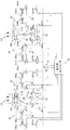
- FIG. 2 is a view showing a configuration example of a traveling hydraulic control system. Since the traveling hydraulic control system has the same configuration as the left and right traveling motors 22L and 22R, hereinafter, the traveling hydraulic control system related to the left traveling motor 22L will be described as an example, A detailed description of the traveling hydraulic control system related to the traveling motor 22R on the right side will be omitted. In the description of the traveling hydraulic control system related to the traveling motor 22L on the left side, when L of the code attached to each component is replaced with R, the traveling hydraulic control system related to the traveling motor 22R on the right side will be described.
- the traveling hydraulic control system includes a hydraulic pump 51L, a hydraulic oil tank 52 for storing hydraulic oil drawn into the hydraulic pump 51L, a traveling motor 22L driven by pressure oil supplied from the hydraulic pump 51L, and a traveling A direction control valve 53L for controlling the flow (flow rate and direction) of pressure oil supplied to the motor 22L, a pilot pump 54, and a traveling operation lever 34L as an operating device for operating the traveling motor 22L;
- a pair of hydraulic pilot valves 55La and 55Lb are provided to generate a pilot pressure which is a hydraulic signal according to the operation of the travel control lever 34L from the pressure oil supplied from the pilot pump 54.
- the hydraulic pump 51L sucks in hydraulic oil from the hydraulic oil tank 52 and supplies it to the traveling motor 22L, and the pilot pump 54 sucks hydraulic oil from the hydraulic oil tank 52 and supplies it to the direction control valve 53L.
- the direction control valve 53L has a first switching position R for rotating the traveling motor 22L forward, a second switching position N for returning pressure oil directly to the hydraulic oil tank 52, and a third switching position L for rotating the traveling motor 22L in reverse. , (Open center type).
- Direction control valve 53L is cut to any one of first to third switching positions R, N, L by the internal spool strokes left and right according to the pilot pressure acting on left and right pressure receiving chambers a and b respectively. It has a configuration to replace it.
- the pressure oil introduced to the travel motor 22L at the first switching position R and the third switching position L flows out to the hydraulic oil tank 52.
- the pair of hydraulic pilot valves 55La and 55Lb respectively generate a pilot pressure according to the amount of operation of the travel control lever 34L.
- the hydraulic pilot valve 55La on the left side is driven to drive the discharge pressure from the pilot pump 54 to the travel control lever. Depressurize to a pressure according to the operating volume of 34 L. Thereby, a pilot pressure for causing the pressure receiving chamber a on the left side of the direction control valve 53L is generated.
- the hydraulic pilot valve 55Lb on the right is driven to discharge the pressure from the pilot pump 54 to the traveling control lever 34L.
- the pressure is reduced to the pressure according to the operation amount of Thereby, a pilot pressure for causing the pressure receiving chamber b on the right side of the direction control valve 53L to be generated. Therefore, the pilot pressures generated by the pair of hydraulic pilot valves 55La and 55Lb are lower than the discharge pressure from the pilot pump 54, respectively.
- the traveling hydraulic control system includes a changeover switch 35L as a switching device that selectively switches the operation mode of the traveling control lever 34L to the “normal mode” or the “control mode”, and a pair of hydraulic pilots.
- control mode is, for example, to suppress occurrence of jerk due to an erroneous operation of the travel control lever 34L by the operator while traveling on a rough road, or to suppress amplification of jerk
- the operation mode in this case is the operation mode
- the “normal mode” is an operation mode in the case where the suppression of the jerk is not particularly required, for example, during the normal operation of the hydraulic shovel 1.
- the state in which the operator presses the changeover switch 35L is the "control mode”
- the state in which the operator removes the finger from the changeover switch 35L is the "normal mode”.
- the pilot pressure detector 56La on the left side of the pair of pilot pressure detectors 56La and 56Lb detects the pilot pressure generated by the hydraulic pilot valve 55La on the left side, and the pilot pressure detector 56Lb on the right side is on the right
- the pilot pressure generated by the hydraulic pilot valve 55Lb is detected. Therefore, the left pilot pressure detector 56La is provided downstream of the left hydraulic pilot valve 55La with respect to the pressure oil flow, and the right pilot pressure detector 56Lb is provided with respect to the pressure oil flow. It is provided downstream of the hydraulic pilot valve 55Lb.
- the configuration for adjusting the pilot pressure applied to the pressure receiving chamber a on the left side of the direction control valve 53L and the configuration for adjusting the pilot pressure applied to the pressure receiving chamber b on the right side of the direction control valve 53L are as follows: Since the configuration is the same, in the following, a configuration for adjusting the pilot pressure applied to the pressure receiving chamber a on the left side of the direction control valve 53L will be described as an example, and applied to the pressure receiving chamber b on the right side Detailed description of the configuration for adjusting the pilot pressure is omitted.
- the pilot pressure adjusting device 5L includes a pilot pipe line 61La, a bypass pipe line 62La, a first electromagnetic pressure reducing valve 610La provided in the pilot pipe line 61La, and a solenoid on-off valve 621La provided in the bypass pipe line 62La.
- the controller 50 includes the electromagnetic pressure reducing valve 622La, and the travel controller 50 that outputs drive signals to the first electromagnetic pressure reducing valve 610La, the electromagnetic on-off valve 621La, and the second electromagnetic pressure reducing valve 622La.
- the pilot pipe line 61La connects the hydraulic pilot valve 55La and the direction control valve 53L, and is a pipe for causing the pilot pressure generated by the hydraulic pilot valve 55La to act on the directional control valve 53L (the pressure receiving chamber a on the left side). is there.
- the first electromagnetic pressure reducing valve 610La is disposed downstream of the pilot pressure detector 56La and upstream of the directional control valve 53L with respect to the flow of pressure oil in the pilot pipeline 61La.
- the degree of opening of the first electromagnetic pressure reducing valve 610La is adjusted by the drive signal output from the traveling controller 50.
- the bypass pipeline 62La connects the pilot pump 54 and the direction control valve 53L by bypassing the hydraulic pilot valve 55La, and directly directs the discharge pressure (pilot pressure) from the pilot pump 54 to the direction control valve 53L (on the left side It is a conduit for acting on the pressure receiving chamber a).
- the electromagnetic on-off valve 621La and the second electromagnetic pressure reducing valve 622La are disposed downstream of the pilot pump 54 and upstream of the directional control valve 53L with respect to the flow of pressure oil in the bypass pipeline 62La.
- the solenoid on-off valve 621La is disposed on the upstream side of the second electromagnetic pressure reducing valve 622La with respect to the flow of the pressure oil.
- the solenoid on-off valve 621La receives the drive signal from the traveling controller 50 and opens the bypass pipeline 62La.
- the second electromagnetic pressure reducing valve 622La has its opening adjusted by the drive signal output from the traveling controller 50, and reduces the discharge pressure from the pilot pump 54 to a predetermined target pilot pressure.
- the pilot pipe line 61La and the bypass pipe line 62La merge with the flow of pressure oil downstream of the first electromagnetic pressure reducing valve 610La and the second electromagnetic pressure reducing valve 622La via the check valve 60La. ing.
- the check valve 60La prevents the pressure oil flowing through the pilot pipe line 61La and the pressure oil flowing through the bypass pipe line 62La from flowing back to the other pipe line.
- both the pilot pipeline 61La and the bypass pipeline 62La are operated. Pressure oil flows in the road.
- the check valve 60La functions to lead the pressure oil having the higher pressure to the direction control valve 53L among the pressure oil flowing through the pilot pipe line 61La and the pressure oil flowing through the bypass pipe line 62La.
- the travel controller 50 receives the signals from the changeover switch 35L and the pilot pressure detector 56La, and after the calculation etc. for adjusting the pilot pressure is internally performed, the first electromagnetic pressure reducing valve 610La and the electromagnetic on-off valve 621La. And drive signals are output to the second electromagnetic pressure reducing valve 622La.
- the traveling controller 50 includes a CPU (Central Processing Unit) that performs various calculations for controlling the pilot pressure applied to the direction control valve 53L, and a program for executing calculations by the CPU.
- a storage medium such as a ROM (Read Only Memory) or an HDD (Hard Disk Drive) to be stored, a RAM (Random Access Memory) as a work area when the CPU executes a program, a pilot pipeline 61La or a bypass pipeline 62La And an I / F (interface) that inputs and outputs signals to and from each of the devices provided in
- ROM Read Only Memory
- HDD Hard Disk Drive
- I / F interface
- the CPU, the ROM, the HDD, the RAM, and the I / F are electrically connected to one another via a bus, and the devices provided in the pilot pipe line 61La and the bypass pipe line 62La are electrically connected to the I / F. It is connected to the.
- the CPU reads the traveling control program stored in the storage medium such as the ROM or the HDD, expands it on the RAM, and executes the expanded traveling control program (software) to execute traveling.
- a control program (software) and hardware cooperate to realize a function as a traveling control system.
- the configuration of the traveling controller 50 has been described using a combination of software and hardware.
- the present invention is not limited to this. .
- the configuration for adjusting the pilot pressure applied to the pressure receiving chamber a on the left side of the direction control valve 53L in the pilot pressure adjusting device 5L has been specifically described, but the pressure receiving chamber b on the right side of the direction control valve 53L is applied Similarly, in the configuration for adjusting the pilot pressure, the pilot pipeline 61Lb, the bypass pipeline 62Lb, the first electromagnetic pressure reducing valve 610Lb, the electromagnetic on-off valve 621Lb, the second electromagnetic pressure reducing valve 622Lb, and the travel controller 50; have.
- the traveling hydraulic control system related to the traveling motor 22R on the right side is the hydraulic pump 51R, the hydraulic oil tank 52, the traveling motor 22R, and the direction control, similarly to the traveling hydraulic control system related to the traveling motor 22L on the left side.
- the pilot pressure adjusting device 5R in the traveling hydraulic control system related to the right traveling motor 22R is similar to the traveling hydraulic control system related to the left traveling motor 22L, the pilot pipelines 61Ra and 61Rb, and the bypass pipeline 62Ra. , 62Rb, first electromagnetic pressure reducing valves 610Ra, 610Rb, electromagnetic on-off valves 621Ra, 621Rb, second electromagnetic pressure reducing valves 622Ra, 622Rb, and a travel controller 50.
- the travel controller 50, the hydraulic oil tank 52, and the pilot pump 54 are common to the entire travel hydraulic control system.
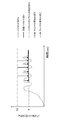
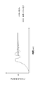
- FIG. 3 is a graph showing a change in pilot pressure while traveling on a rough road, and a predetermined target pilot pressure P set in the pilot pressure adjustment device 5L.
- pilot pressure Po The detected pilot pressure Po (hereinafter simply referred to as "pilot pressure Po") has a vibration period as shown by a solid line in FIG. Then, in synchronization with this vibration cycle, the operator may unintentionally operate the traveling control lever 34L unintentionally, and the pilot pressure Po greatly fluctuates according to the operation amount caused by the erroneous operation of the traveling control lever 34L.
- pilot pressure adjusting device 5L reduces the fluctuating pilot pressure Po to a predetermined target pilot pressure P (hereinafter, simply referred to as “target pilot pressure P”) to set the directional control valve 53L. It acts as an operation signal.
- the pilot pressure Po is equal to or higher than the target pilot pressure P (Po ⁇ P)
- the pilot pressure Po is reduced to the target pilot pressure P, as shown by the lower arrow of the broken line in FIG.
- the first electromagnetic pressure reducing valve 610La receiving the drive signal output from the traveling controller 50 reduces the pilot pressure Po to the target pilot pressure P.
- the discharge pressure Pd from the pilot pump 54 (indicated by a two-dot chain line in FIG. 3) as indicated by a solid arrow in FIG. ) Is reduced to the target pilot pressure P.
- the solenoid on-off valve 621La receiving the drive signal output from the traveling controller 50 opens the bypass conduit 62La, and the second electromagnetic pressure reducing valve 622La receiving the drive signal discharges the pilot pump 54.
- the pressure Pd is reduced to the target pilot pressure P.
- the pilot pressure Po when the pilot pressure Po is lower than the target pilot pressure P (Po ⁇ P), the pilot pressure Po is not boosted to the target pilot pressure P, and a pilot pump having a pressure higher than the pilot pressure Po.
- the discharge pressure Pd from 54 is reduced to the target pilot pressure P.
- the target pilot pressure P with no fluctuation can be applied to the direction control valve 53L, the pilot pressure Po generated by the hydraulic pilot valve 55La greatly fluctuates in response to the erroneous operation of the travel control lever 34L. Even in this case, the occurrence of jerking of the vehicle body can be suppressed, and the amplification of the jerking can be suppressed.
- the traveling controller 50 in the pilot pressure adjusting device 5L will be described.
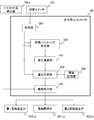
- FIG. 4 is a functional block diagram showing functions of the traveling controller 50. As shown in FIG.
- the traveling controller 50 includes a receiving unit 501, a target pilot pressure setting unit 502, a differential pressure calculation unit 503, a differential pressure determination unit 504, a threshold storage unit 505, and a drive command unit 506.
- the receiving unit 501 receives a signal from the changeover switch 35L.
- the operation mode of the travel operation lever 34L is maintained in the “control mode” state, and the reception unit 501
- the operation mode of the travel control lever 34L is switched from the "control mode” to the "normal mode”.
- the target pilot pressure setting unit 502 switches the operation mode of the travel control lever 34L to the “control mode” by the changeover switch 35L based on the information from the reception unit 501 and the signal from the pilot pressure detector 56La
- the pilot pressure (pilot pressure Po) detected by the pilot pressure detector 56La in the above is set as a target pilot pressure P.
- the differential pressure calculation unit 503 calculates the differential pressure between the pilot pressure Po and the target pilot pressure P based on the information from the target pilot pressure setting unit 502 and the signal from the pilot pressure detector 56La (hereinafter simply referred to as “differential pressure”). To calculate).
- the differential pressure determination unit 504 compares the differential pressure with the threshold based on the information from the differential pressure calculation unit 503 and the threshold storage unit 505 to determine the magnitude relationship of the differential pressure with respect to the threshold.
- a predetermined first threshold ⁇ and a predetermined second threshold ⁇ are stored in the threshold storage unit 505 in advance.
- drive command unit 506 Based on the information from differential pressure determination unit 504 and the signal from pilot pressure detector 56La, drive command unit 506 causes pilot pressure Po to be a predetermined pilot pressure (pilot pressure Po or target pilot pressure), Drive signals are output to the first electromagnetic pressure reducing valve 610La, the electromagnetic on-off valve 621La, and the second electromagnetic pressure reducing valve 622La.
- the drive command unit 506 outputs a drive signal so as to be the pilot pressure Po to the first electromagnetic pressure reducing valve 610La.
- the drive command unit 506 performs the first operation when the pilot pressure Po is equal to or higher than the target pilot pressure P (Po ⁇ P).
- a drive signal is output to the target pilot pressure P to the electromagnetic pressure reducing valve 610La, and when the pilot pressure Po is lower than the target pilot pressure P (Po ⁇ P), The drive signal is output to become the target pilot pressure P with respect to the second electromagnetic pressure reducing valve 622La.
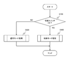
- FIG. 5 is a flowchart showing an outline of the flow of processing executed by the traveling controller 50.
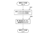
- FIG. 6 is a flowchart showing the flow of the normal mode process executed by the traveling controller 50.
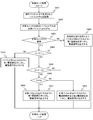
- FIG. 7 is a flowchart showing a flow of control mode processing executed by the traveling controller 50.
- FIG. 8 is a graph for explaining how the pilot pressure changes when delay processing is performed.
- FIG. 9 is a graph for explaining the state of the pilot pressure when the differential pressure between the pilot pressure Po and the target pilot pressure P is equal to or less than a predetermined first threshold value ⁇ .
- the receiving unit 501 monitors the signal from the pilot pressure detector 56La, and determines whether or not the signal from the changeover switch 35L is received while the hydraulic shovel 1 is traveling, that is, the changeover switch 35L. It is determined whether or not is pressed (step S700).
- step S700 when the reception unit 501 does not receive the signal from the changeover switch 35L (step S700 / NO), the process proceeds to the "normal mode process" (step S800), and the process ends. In this case, the normal operation of the hydraulic shovel 1 or the suppression of the jerking is unnecessary.
- step S700 when the reception unit 501 receives a signal from the changeover switch 35L (step S700 / YES), the process proceeds to "control mode process" (step S900), and the process ends.
- step S800 the traveling controller 50 acquires the pilot pressure Po (the pilot pressure generated by the hydraulic pilot valve 55La according to the operation amount of the traveling control lever 34L) from the pilot pressure detector 56La (step S801).
- the pilot pressure Po the pilot pressure generated by the hydraulic pilot valve 55La according to the operation amount of the traveling control lever 34L
- the drive command unit 506 outputs a drive signal to the first electromagnetic pressure reducing valve 610La so that the pilot pressure Po is obtained (the pilot pressure Po is applied as it is) (step S803), and the process ends.
- the target pilot pressure setting unit 502 acquires the pilot pressure Po (the pilot pressure generated by the hydraulic pilot valve 55La according to the operation amount of the travel control lever 34L) from the pilot pressure detector 56La.
- the pilot pressure Po is set as the target pilot pressure P when the changeover switch 35L is pressed, that is, when the operation mode of the travel control lever 34L is switched to the "control mode" (step S902).
- the receiving unit 501 determines whether or not the signal from the changeover switch 35L is continuously received, that is, whether or not the operation mode of the traveling operation lever 34L maintains the state of “control mode” (step S903).
- step S 903 when the receiving unit 501 continuously receives the signal from the changeover switch 35 L (step S 903 / YES), the differential pressure determination unit 504 calculates the differential pressure calculated by the differential pressure calculation unit 503. Whether (
- the predetermined first threshold value ⁇ is a numerical value relatively close to 0 MPa, such as 0.2 MPa, for example.
- step S903 the case where the reception unit 501 does not continuously receive the signal from the changeover switch 35L (step S903 / NO) will be described later.
- the differential pressure determination unit 504 When it is determined in step S904 that the differential pressure is larger than the predetermined first threshold value ⁇ (
- the predetermined second threshold value ⁇ is a numerical value such as 1 MPa, for example, and is a larger value than the predetermined first threshold value ⁇ .
- step S905 the flow of processing proceeds to step S905 after step S904, but the order does not necessarily have to be followed, and the processing may proceed to step S904 after step S905, or Only one of steps S904 and S905 may be performed.
- step S904 If it is determined in step S904 that the differential pressure is equal to or less than the predetermined first threshold value ⁇ (
- the pilot pressure Po approximates the target pilot pressure P.
- the operator forgets to release the changeover switch 35L by performing processing for causing a pilot pressure (pilot pressure Po) corresponding to the operation amount of the travel control lever 34L to act on the direction control valve 53L.
- a pilot pressure pilot pressure Po
- the same operation as in the normal operation can be performed.
- step S 905 when the differential pressure is smaller than second threshold value ⁇ (
- step S905 the case where the differential pressure is equal to or greater than the predetermined second threshold value ⁇ (
- step S906 when pilot pressure Po is equal to or higher than target pilot pressure P (Po P P), drive command unit 506 outputs a drive signal such that target pilot pressure P is achieved for first electromagnetic pressure reducing valve 610La. (Step S 907), and the process ends. Thereby, the first electromagnetic pressure reducing valve 610La reduces the pressure (pilot pressure Po) of the pressure oil flowing through the pilot pipeline 61La to the target pilot pressure P.
- step S906 when pilot pressure Po is smaller than target pilot pressure P (Po ⁇ P), drive command unit 506 outputs a drive signal to electromagnetic valve 621La to be "open". A drive signal is output to the second electromagnetic pressure reducing valve 622La such that the target pilot pressure P is obtained (step S908), and the process ends.
- the solenoid on-off valve 621La opens the bypass pipeline 62La, and the second electromagnetic pressure reducing valve 622La sets the pressure (discharge pressure Pd) of the pressure oil from the pilot pump 54 flowing through the bypass pipeline 62La to the target pilot. The pressure is reduced to P.
- step S903 when the reception unit 501 does not continuously receive the signal from the changeover switch 35L, and when the differential pressure is equal to or higher than the predetermined second threshold value ⁇ in step S905 (
- the drive command unit 506 delays the time (t [sec] shown in FIG. 8), and the pilot pressure (pilot) corresponding to the operation amount of the travel control lever 34L.
- a drive signal to which a temporal delay element is added so as to become the pressure Po) is output to the first electromagnetic pressure reducing valve 610La (step S909), and the process is ended.
- the drive command unit 506 simply outputs the drive signal to the first electromagnetic pressure reducing valve 610La without giving a time delay, as shown by a dot-and-dash line in FIG.
- the pilot pressure changes rapidly, and the vehicle body may vibrate largely.
- the drive command unit 506 outputs a drive signal to which a time delay element is added to the first electromagnetic pressure reducing valve 610La, so that the opening degree of the first electromagnetic pressure reducing valve 610La is Since it is gradually adjusted, it is possible to realize a smooth traveling of the hydraulic shovel 1 by suppressing a rapid change of the pilot pressure applied to the direction control valve 53L.
- a first-order lag element is used for this temporal delay element, but it does not have to be a first-order lag element.
- step S903 when the reception unit 501 does not continuously receive the signal from the changeover switch 35L (step S903 / No), the operation mode of the travel operation lever 34L is changed from the "control mode" to the "normal mode". (When the operator takes his / her finger off the changeover switch 35L), the process corresponds to the process of transitioning from the control mode process to the normal mode process.
- step S 905 when the differential pressure is equal to or higher than the predetermined second threshold value ⁇ (
- the pilot pressure with fluctuation is controlled to the pilot pressure without fluctuation (the target pilot pressure P) and then applied to the directional control valve 53L.
- the control state of the pilot pressure is gradually released to suppress the occurrence of unnecessary vehicle body jerking or the jar The amplification of the king can be suppressed, and the operability by the operator can be improved.
- the present invention has been described above.
- the present invention is not limited to the above-described embodiment, but includes various modifications.
- the above-described embodiment is described in detail to explain the present invention in an easy-to-understand manner, and is not necessarily limited to one having all the described configurations.
- part of the configuration of the present embodiment can be replaced with the configuration of the other embodiment, and the configuration of the other embodiment can be added to the configuration of the present embodiment.
- the travel operation levers 34L and 34R have been described as the operation device, but the operation levers do not necessarily have to be levers operated by the operator manually, and may be, for example, travel operation pedals.
- the changeover switches 35L and 35R as the switching devices are switches such that the state of the "control mode" is maintained when the operator keeps pressing, but the specification of the switching devices is particularly limited There is no.
- the traveling controller 50 includes the receiving unit 501, and the information of ON or OFF of the changeover switch 35L is based on the information from the receiving unit 501, but the information from the receiving unit 501 is not always necessary.
- a signal may be input to each part of the traveling controller 50 directly from the changeover switches 35L and 35R without needing to be based on that.
- the traveling motors 22L and 22R have been described as the hydraulic actuators.
- the present invention is not limited to this.
- other hydraulic actuators such as the boom cylinder 40a, the arm cylinder 40b, and the bucket cylinder 40c may be used.
- crawler type hydraulic shovel 1 has been described as a construction machine in the above embodiment, it does not necessarily have to be a crawler type construction machine, for example, a wheel type construction machine such as a wheel type hydraulic shovel Good.
- step S900 at least the pilot pressure Po detected by the pilot pressure detector 56La when the operation mode of the travel control lever 34L is switched to the control mode by the changeover switch 35L is set to the target pilot pressure P
- the process may be any process as long as the drive signal is set such that the pilot pressure applied to the direction control valve 53L becomes the target pilot pressure P.
Landscapes
- Engineering & Computer Science (AREA)
- General Engineering & Computer Science (AREA)
- Mining & Mineral Resources (AREA)
- Civil Engineering (AREA)
- Structural Engineering (AREA)
- Physics & Mathematics (AREA)
- Fluid Mechanics (AREA)
- Mechanical Engineering (AREA)
- Chemical & Material Sciences (AREA)
- Analytical Chemistry (AREA)
- Operation Control Of Excavators (AREA)
- Fluid-Pressure Circuits (AREA)
Priority Applications (4)
| Application Number | Priority Date | Filing Date | Title |
|---|---|---|---|
| CN201880003186.2A CN109642591B (zh) | 2017-02-20 | 2018-02-20 | 工程机械 |
| KR1020197004291A KR102097536B1 (ko) | 2017-02-20 | 2018-02-20 | 건설 기계 |
| US16/329,032 US10677268B2 (en) | 2017-02-20 | 2018-02-20 | Construction machine |
| EP18754729.4A EP3492755B1 (en) | 2017-02-20 | 2018-02-20 | Construction machine |
Applications Claiming Priority (2)
| Application Number | Priority Date | Filing Date | Title |
|---|---|---|---|
| JP2017029305A JP6683640B2 (ja) | 2017-02-20 | 2017-02-20 | 建設機械 |
| JP2017-029305 | 2017-02-20 |
Publications (1)
| Publication Number | Publication Date |
|---|---|
| WO2018151323A1 true WO2018151323A1 (ja) | 2018-08-23 |
Family
ID=63169924
Family Applications (1)
| Application Number | Title | Priority Date | Filing Date |
|---|---|---|---|
| PCT/JP2018/006055 Ceased WO2018151323A1 (ja) | 2017-02-20 | 2018-02-20 | 建設機械 |
Country Status (6)
| Country | Link |
|---|---|
| US (1) | US10677268B2 (enExample) |
| EP (1) | EP3492755B1 (enExample) |
| JP (1) | JP6683640B2 (enExample) |
| KR (1) | KR102097536B1 (enExample) |
| CN (1) | CN109642591B (enExample) |
| WO (1) | WO2018151323A1 (enExample) |
Cited By (1)
| Publication number | Priority date | Publication date | Assignee | Title |
|---|---|---|---|---|
| JP7496910B1 (ja) | 2023-03-31 | 2024-06-07 | 日立建機株式会社 | 建設機械の油圧制御システム |
Families Citing this family (7)
| Publication number | Priority date | Publication date | Assignee | Title |
|---|---|---|---|---|
| JP6634363B2 (ja) * | 2016-11-16 | 2020-01-22 | 日立建機株式会社 | 作業機械 |
| JP7123735B2 (ja) * | 2018-10-23 | 2022-08-23 | ヤンマーパワーテクノロジー株式会社 | 建設機械及び建設機械の制御システム |
| JP7110164B2 (ja) * | 2019-09-25 | 2022-08-01 | 株式会社日立建機ティエラ | 建設機械 |
| JP7345386B2 (ja) * | 2019-12-25 | 2023-09-15 | 株式会社クボタ建設 | 製管機 |
| CN111794306B (zh) * | 2020-07-15 | 2023-03-24 | 徐州徐工挖掘机械有限公司 | 先导油压力控制方法、装置、控制器以及存储介质 |
| JP7681417B2 (ja) * | 2021-03-29 | 2025-05-22 | 日立建機株式会社 | 建設機械 |
| EP4074937A1 (en) | 2021-04-12 | 2022-10-19 | Bay Shore Systems Inc. | Skid-steer loader attachment assemblies and methods for performing earth augering using a skid-steer loader |
Citations (1)
| Publication number | Priority date | Publication date | Assignee | Title |
|---|---|---|---|---|
| JPH08189502A (ja) * | 1995-01-11 | 1996-07-23 | Komatsu Ltd | 主切換弁のパイロット操作油圧回路 |
Family Cites Families (18)
| Publication number | Priority date | Publication date | Assignee | Title |
|---|---|---|---|---|
| JPH053364A (ja) * | 1991-06-21 | 1993-01-08 | Nippon Telegr & Teleph Corp <Ntt> | 半導体レーザ |
| JP2892939B2 (ja) * | 1994-06-28 | 1999-05-17 | 日立建機株式会社 | 油圧掘削機の油圧回路装置 |
| JP4011234B2 (ja) | 1999-06-10 | 2007-11-21 | 株式会社加藤製作所 | アクチュエータ作動装置 |
| JP3557167B2 (ja) * | 2000-11-20 | 2004-08-25 | 新キャタピラー三菱株式会社 | 作業用機械における油圧回路 |
| KR100929420B1 (ko) * | 2006-12-28 | 2009-12-03 | 볼보 컨스트럭션 이키프먼트 홀딩 스웨덴 에이비 | 굴삭기의 붐 충격 완화장치 및 그 제어방법 |
| JP5175870B2 (ja) * | 2010-01-13 | 2013-04-03 | 川崎重工業株式会社 | 作業機械の駆動制御装置 |
| JP5548113B2 (ja) * | 2010-12-17 | 2014-07-16 | 川崎重工業株式会社 | 作業機械の駆動制御方法 |
| CN202508776U (zh) * | 2012-02-28 | 2012-10-31 | 三一汽车起重机械有限公司 | 一种双操控模式的先导控制系统及起重机 |
| JP2014065324A (ja) | 2012-09-24 | 2014-04-17 | Hitachi Constr Mach Co Ltd | 作業車両 |
| JP6013503B2 (ja) * | 2012-11-08 | 2016-10-25 | 日立建機株式会社 | 建設機械 |
| CN203847458U (zh) * | 2014-03-10 | 2014-09-24 | 杭州科技职业技术学院 | 一种同时可以电控和手控的先导结构 |
| JP6013389B2 (ja) * | 2014-03-24 | 2016-10-25 | 日立建機株式会社 | 作業機械の油圧システム |
| JP6259371B2 (ja) | 2014-07-31 | 2018-01-10 | 株式会社クボタ | 作業機 |
| WO2016085959A1 (en) * | 2014-11-24 | 2016-06-02 | Parker-Hannifin Corporation | System architectures for steering and work functions in a wheel loader |
| CN104595273B (zh) * | 2015-01-14 | 2017-03-01 | 柳州柳工挖掘机有限公司 | 工程机械精细化操作液压系统 |
| JP6316776B2 (ja) * | 2015-06-09 | 2018-04-25 | 日立建機株式会社 | 作業機械の油圧駆動システム |
| CN106321541B (zh) * | 2016-08-30 | 2018-03-27 | 中煤科工集团西安研究院有限公司 | 一种车载钻机电液双控液压系统及方法 |
| EP3517789B1 (en) * | 2016-09-23 | 2023-09-13 | Hitachi Construction Machinery Co., Ltd. | Hydraulic energy recovery device for work machine |
-
2017
- 2017-02-20 JP JP2017029305A patent/JP6683640B2/ja active Active
-
2018
- 2018-02-20 CN CN201880003186.2A patent/CN109642591B/zh active Active
- 2018-02-20 EP EP18754729.4A patent/EP3492755B1/en active Active
- 2018-02-20 US US16/329,032 patent/US10677268B2/en active Active
- 2018-02-20 KR KR1020197004291A patent/KR102097536B1/ko active Active
- 2018-02-20 WO PCT/JP2018/006055 patent/WO2018151323A1/ja not_active Ceased
Patent Citations (1)
| Publication number | Priority date | Publication date | Assignee | Title |
|---|---|---|---|---|
| JPH08189502A (ja) * | 1995-01-11 | 1996-07-23 | Komatsu Ltd | 主切換弁のパイロット操作油圧回路 |
Cited By (3)
| Publication number | Priority date | Publication date | Assignee | Title |
|---|---|---|---|---|
| JP7496910B1 (ja) | 2023-03-31 | 2024-06-07 | 日立建機株式会社 | 建設機械の油圧制御システム |
| WO2024202526A1 (ja) * | 2023-03-31 | 2024-10-03 | 日立建機株式会社 | 建設機械の油圧制御システム |
| JP2024146191A (ja) * | 2023-03-31 | 2024-10-15 | 日立建機株式会社 | 建設機械の油圧制御システム |
Also Published As
| Publication number | Publication date |
|---|---|
| US20190219071A1 (en) | 2019-07-18 |
| JP2018135913A (ja) | 2018-08-30 |
| CN109642591A (zh) | 2019-04-16 |
| KR20190027899A (ko) | 2019-03-15 |
| KR102097536B1 (ko) | 2020-04-06 |
| JP6683640B2 (ja) | 2020-04-22 |
| US10677268B2 (en) | 2020-06-09 |
| EP3492755A1 (en) | 2019-06-05 |
| EP3492755A4 (en) | 2020-04-22 |
| EP3492755B1 (en) | 2021-04-14 |
| CN109642591B (zh) | 2020-10-23 |
Similar Documents
| Publication | Publication Date | Title |
|---|---|---|
| WO2018151323A1 (ja) | 建設機械 | |
| JP4764923B2 (ja) | 油圧走行車両および油圧走行車両の制御方法 | |
| JP4764922B2 (ja) | 油圧走行車両 | |
| JP6474908B2 (ja) | 作業機械の油圧システム | |
| WO2006077759A1 (ja) | 建設機械の制御モード切換装置および建設機械 | |
| JP4972544B2 (ja) | 作業機械を揺動させる方法 | |
| KR20130140019A (ko) | 휠식 작업기의 유압 구동 장치 | |
| JP2014142032A (ja) | 液圧駆動装置 | |
| JP6850707B2 (ja) | 作業機械 | |
| JP2006219975A (ja) | 移動機械のための半能動走行制御 | |
| JPWO2018179113A1 (ja) | 作業車両 | |
| JP2933806B2 (ja) | 建設機械の油圧駆動装置 | |
| JP2005155230A (ja) | 車輪式建設機械の走行振動抑制油圧回路 | |
| JPH08219107A (ja) | 油圧機械の油圧再生装置 | |
| JP7342456B2 (ja) | 油圧制御装置 | |
| JP7546123B2 (ja) | バルブシステム | |
| JP3788686B2 (ja) | 油圧駆動制御装置 | |
| JP4136892B2 (ja) | 建設機械の油圧制御回路 | |
| JP6591370B2 (ja) | 建設機械の油圧制御装置 | |
| JP2000145717A (ja) | 建設機械の油圧シリンダ制御装置 | |
| JP2948064B2 (ja) | 建設機械の油圧駆動装置 | |
| JP7268504B2 (ja) | 油圧制御装置 | |
| JP2006045852A (ja) | 液圧回路の液圧制御装置 | |
| JPH09165791A (ja) | 作業機械の油圧回路 | |
| JP2768491B2 (ja) | 装軌式車両の油圧駆動装置 |
Legal Events
| Date | Code | Title | Description |
|---|---|---|---|
| 121 | Ep: the epo has been informed by wipo that ep was designated in this application |
Ref document number: 18754729 Country of ref document: EP Kind code of ref document: A1 |
|
| ENP | Entry into the national phase |
Ref document number: 20197004291 Country of ref document: KR Kind code of ref document: A |
|
| ENP | Entry into the national phase |
Ref document number: 2018754729 Country of ref document: EP Effective date: 20190227 |
|
| NENP | Non-entry into the national phase |
Ref country code: DE |