WO2018151120A1 - Dispositif de prévention de renversement d'article - Google Patents
Dispositif de prévention de renversement d'article Download PDFInfo
- Publication number
- WO2018151120A1 WO2018151120A1 PCT/JP2018/004955 JP2018004955W WO2018151120A1 WO 2018151120 A1 WO2018151120 A1 WO 2018151120A1 JP 2018004955 W JP2018004955 W JP 2018004955W WO 2018151120 A1 WO2018151120 A1 WO 2018151120A1
- Authority
- WO
- WIPO (PCT)
- Prior art keywords
- fall prevention
- link
- end side
- rod
- rear end
- Prior art date
Links
Images


Classifications
-
- B—PERFORMING OPERATIONS; TRANSPORTING
- B65—CONVEYING; PACKING; STORING; HANDLING THIN OR FILAMENTARY MATERIAL
- B65G—TRANSPORT OR STORAGE DEVICES, e.g. CONVEYORS FOR LOADING OR TIPPING, SHOP CONVEYOR SYSTEMS OR PNEUMATIC TUBE CONVEYORS
- B65G1/00—Storing articles, individually or in orderly arrangement, in warehouses or magazines
- B65G1/02—Storage devices
-
- A—HUMAN NECESSITIES
- A47—FURNITURE; DOMESTIC ARTICLES OR APPLIANCES; COFFEE MILLS; SPICE MILLS; SUCTION CLEANERS IN GENERAL
- A47B—TABLES; DESKS; OFFICE FURNITURE; CABINETS; DRAWERS; GENERAL DETAILS OF FURNITURE
- A47B97/00—Furniture or accessories for furniture, not provided for in other groups of this subclass
-
- A—HUMAN NECESSITIES
- A47—FURNITURE; DOMESTIC ARTICLES OR APPLIANCES; COFFEE MILLS; SPICE MILLS; SUCTION CLEANERS IN GENERAL
- A47B—TABLES; DESKS; OFFICE FURNITURE; CABINETS; DRAWERS; GENERAL DETAILS OF FURNITURE
- A47B96/00—Details of cabinets, racks or shelf units not covered by a single one of groups A47B43/00 - A47B95/00; General details of furniture
-
- B—PERFORMING OPERATIONS; TRANSPORTING
- B65—CONVEYING; PACKING; STORING; HANDLING THIN OR FILAMENTARY MATERIAL
- B65G—TRANSPORT OR STORAGE DEVICES, e.g. CONVEYORS FOR LOADING OR TIPPING, SHOP CONVEYOR SYSTEMS OR PNEUMATIC TUBE CONVEYORS
- B65G1/00—Storing articles, individually or in orderly arrangement, in warehouses or magazines
- B65G1/02—Storage devices
- B65G1/14—Stack holders or separators
-
- A—HUMAN NECESSITIES
- A47—FURNITURE; DOMESTIC ARTICLES OR APPLIANCES; COFFEE MILLS; SPICE MILLS; SUCTION CLEANERS IN GENERAL
- A47B—TABLES; DESKS; OFFICE FURNITURE; CABINETS; DRAWERS; GENERAL DETAILS OF FURNITURE
- A47B97/00—Furniture or accessories for furniture, not provided for in other groups of this subclass
- A47B2097/008—Anti-tip devices
-
- B—PERFORMING OPERATIONS; TRANSPORTING
- B65—CONVEYING; PACKING; STORING; HANDLING THIN OR FILAMENTARY MATERIAL
- B65G—TRANSPORT OR STORAGE DEVICES, e.g. CONVEYORS FOR LOADING OR TIPPING, SHOP CONVEYOR SYSTEMS OR PNEUMATIC TUBE CONVEYORS
- B65G2207/00—Indexing codes relating to constructional details, configuration and additional features of a handling device, e.g. Conveyors
- B65G2207/20—Earthquake protection
-
- B—PERFORMING OPERATIONS; TRANSPORTING
- B65—CONVEYING; PACKING; STORING; HANDLING THIN OR FILAMENTARY MATERIAL
- B65G—TRANSPORT OR STORAGE DEVICES, e.g. CONVEYORS FOR LOADING OR TIPPING, SHOP CONVEYOR SYSTEMS OR PNEUMATIC TUBE CONVEYORS
- B65G2207/00—Indexing codes relating to constructional details, configuration and additional features of a handling device, e.g. Conveyors
- B65G2207/40—Safety features of loads, equipment or persons
Definitions
- the present invention is to prevent a product or part mounted on a mounting plate such as a shelf, rack or cabinet from falling or dropping from the mounting plate due to vibration such as an earthquake. It is related with the fall prevention apparatus of the mounted material used for.
- JP 2010-273955 A Patent Document 1
- the stored item fall prevention unit disclosed in this publication is such that the fall prevention arm descends from a standby state by driving an actuator that operates in response to a signal from a seismometer that detects vibration due to an earthquake.
- the stored item fall prevention unit disclosed in Patent Document 1 the stored item does not fall by coming into contact with the fall preventing arm that has been lowered due to the occurrence of an earthquake.
- the seismometer and the actuator are constituent elements, and these operate electrically, so that not only a power source is necessarily required but also a power failure due to an earthquake. Does not work.
- the present invention has been proposed to solve the above-described problems of the prior art, and does not include any electrically operated member at all, and is placed by vibration such as an earthquake. It is an object of the present invention to provide a novel device for preventing a fall of a placed object that can prevent the placed object from falling.
- the present invention has been proposed in order to solve the above-mentioned problems.
- the front side is released and the placed object is accommodated inside.
- a right rotating rod that is arranged to be rotatable about a right support shaft having a length, and a left end is connected to a front end side or a rear end side of the left rotating rod, and a right end is the right rotating rod.
- a load support member connected to the front end side or the rear end side and supporting all or part of the load of the figurine described above, and the front end side or the rear end side of the load support member, or the left rotation rod or the right rotation
- An elastic member that is urged so that the front end side or the rear end side of the bag is always positioned upward, and the load support In the standby state before the placement object is placed on the material, it stands by at a standby position that is above or obliquely above the load support member, and falls after the placement object is placed on the load support member
- a fall prevention member that moves from the standby position to the front side of the placement object, and the left support shaft is rotated counterclockwise at either the front end side or the rear end side of the left rotation rod.
- the right support shaft supports the right rotation shaft on either the front end side or the rear end side of the right rotation shaft, and the left end of the fall prevention member and the left rotation
- the scissors are connected to each other by a linear connecting material made of a linear body, a link connecting material made of a single or a plurality of link members, or a composite connecting material made of the linear body and a plurality of link members,
- the right end of the fall prevention member and the right turning rod are linearly connected with a linear body.
- an insertion space is formed below the anti-falling member into which the object lifting means constituting the fork of the forklift or other machine or apparatus for lifting the object from above the load support member is inserted from the front side. It is characterized by.
- the device for preventing overturning of the mounted object is formed with a mounted object storage space in which the mounted object is stored inside while the front side is released.
- the member forming the accommodation space may be a left side plate or a right side plate (refer to the invention described in claim 2), or a left frame or a right frame (claim 8). (See invention of the present invention).
- the left rotation rod and the right rotation rod are provided.
- the left rotation rod and the right rotation rod are rotatable about a left or right support shaft having a length in the horizontal direction.
- the left support shaft supports the left rotation shaft at either the front end side or the rear end side of the left rotation shaft, and the right support shaft supports the front end side or the rear end of the right rotation shaft.
- the right turning rod is pivotally supported on either one of the sides.
- the load support member is a component, and the load support member has a left end connected to the left rotation rod and a right end connected to the right rotation rod. It supports all or part of the load. Therefore, the left support shaft pivotally supports the left rotation rod on the front end side of the left rotation rod, the right support shaft pivotally supports the right rotation rod on the front end side of the right rotation rod, In addition, when the left end of the load support member is connected to the front end side of the left rotation rod and the right end of the load support member is connected to the front end side of the right rotation rod, the load support member is mounted on the load support member.
- the rear ends of the left rotating rod and the right rotating rod are larger than the lengths at which the front ends of the left rotating rod and the right rotating rod are lowered.
- the left support shaft pivotally supports the left rotation rod at the rear end side of the left rotation rod
- the right support shaft pivots the right rotation rod at the rear end side of the right rotation rod.
- this load support member should just support at least one part of the load of a mounting object, and the shape and area are not specifically limited.
- most of the load of the mounted object is supported by the bottom plate, and a part of the load may be a bar arranged horizontally so as to be supported by the load supporting member, or the entire mounted object may be mounted. It may be configured by a plate body to be placed.
- the elastic member is a constituent element.
- This elastic member may be urged so that the front end side or the rear end side of the load supporting member is always positioned upward, or the front end side of the left rotating rod or the right rotating rod or The rear end side may be urged so as to be always positioned upward.
- the elastic member is an elastic member that urges the left rotating rod when the front rotating end or the rear rotating end of the right rotating rod is always positioned upward.
- the elastic member that urges the right rotating rod may be disposed separately.
- the members are not limited to those disposed below the load support member, the left pivot rod, or the right pivot rod, but may be disposed above them.
- the shape of the elastic member may be a string spring or a leaf spring.
- the fall prevention member is a constituent element.
- the fall prevention member In the standby state before the placing object is placed on the load support member, the fall prevention member stands by at a standby position that is above or obliquely above the load support member, and is placed on the load support member.
- the object In the fall prevention state after the object is placed, the object moves from the standby position to the front side of the object.
- the left end of this fall prevention member and the above-mentioned left rotation rod are a linear connecting material consisting of a linear body, a link connecting material consisting of a single or a plurality of link members, or the above linear body and a plurality of links
- the right end of the fall-preventing member and the right pivot rod are composed of a linear coupling material composed of a linear body, or a single or a plurality of link members. It is mutually connected by the link connection material or the composite connection material which consists of the said linear body and a some link member. Therefore, according to the present invention, when an object is placed on the load support member, the fall prevention member is in the standby state via the linear connecting member, the link connecting member, or the composite connecting member. To the fall prevention state.
- the forelift lifting means constituting the fork or other machine or device of the forklift for lifting the placement from the load support member is in front.
- An insertion space to be inserted from the side is formed below the fall prevention member.
- the fall prevention device for a placement object when all or a part of the load of the placement object is supported by the load support member by the above-described object lifting means, the elastic force of the elastic member is reduced.
- the left rotating rod rotates about the left supporting shaft
- the right rotating shaft rotates about the right supporting shaft.
- the rear end side or the front end side of the right rotating rod rises over a distance longer than the distance by which the load supporting member descends, and the rotation of the left rotating rod and the right rotating rod and the linear shape
- the above-mentioned figurine lifting means can be moved outside in the state which left the above-mentioned figurine left. it can. In this state, when the above-described figurine is tilted in a direction to fall due to vibration such as an earthquake, the placed article comes into contact with the fall-preventing member and is prevented from falling.
- the load is supported by the load support member by vibration such as an earthquake without using any electrically operated member as a constituent element and only by a mechanical structure. It is possible to prevent the placed object from falling, and it is possible to reliably prevent the placed object from falling even when a power failure occurs due to the occurrence of an earthquake or the like.
- the above-mentioned figurine accommodation space includes a bottom plate, a left side plate standing on the left side of the bottom plate, and a right side of the bottom plate. And the right side plate that faces the left side plate, and the load supporting member is disposed above the bottom plate, and the load supporting member is made to be elastic by the load of the mounted object. When it descends against the elastic force, it comes into contact with the upper surface of the bottom plate.
- the load is supported by vibration such as an earthquake without using any electrically operated member as a constituent element. It is possible not only to prevent the mounted object whose load is supported by the member from falling, but also to reliably prevent the mounted object from falling even if a power failure occurs due to the occurrence of an earthquake or the like.
- the load support member comes into contact with the upper surface of the bottom plate, so that the placement portion can be placed in a more stable state.
- the invention according to a third aspect is that, in the second aspect, the overturn prevention member is positioned on an upper end side on a front end side of the left side plate and the right side plate in the standby state. In the fall prevention state, it is located in the middle part of the front end side of the left side plate and the right side plate and is located on the front side of the above-mentioned figurine, and on the front side of the left side plate and the right side plate, Position holding means for holding the position of the fall prevention member when the above-mentioned figurine abuts on the back surface is disposed, and the left end of the fall prevention member and the left rotation rod are the linear connecting members Connected to the end of the linear body constituting the composite connecting member, and the right end of the overturn prevention member and the right rotation rod are the linear Connected by a linear body constituting the connecting material, or the composite When the placing object is placed on the load support member and connected to the end of the linear body constituting the general connecting member, the left turning rod turns around the
- both the left and right ends of the fall prevention member are suspended by the linear body, and the fall prevention member descends when the object to be placed is placed on the load support member.
- the load is raised and the standby state is reached. That is, according to the third aspect of the present invention, the fall prevention member can be raised and lowered, and when the fall prevention member descends to reach the above-described fall prevention state, an earthquake or the like occurs and the mounted article falls to prevent the fall.
- the position holding means holds the position of the fall prevention member.
- a left guide plate facing the front surface is provided on the front side of the left side plate, and the inside of the left guide plate forms a left guide space, and the front side of the right side plate
- a right guide plate facing the front is provided on the inner side of the right guide plate so that the inner side of the right guide plate serves as a right guide space, the left end side of the fall prevention member is disposed in the left guide space, and the right end side of the fall prevention member Is placed in the right guide space, and the above-mentioned figurine comes into contact with the fall prevention member, the left end side of the fall prevention member comes into contact with the back surface of the left guide plate and the right end side of the fall prevention member
- the fall prevention member may hold the position.
- 4th invention is either the said 1st, 2nd or 3rd invention
- the left end of the said fall prevention member and the said left rotation rod are said composite connection.
- the right end of the fall prevention member and the right turning rod are connected to each other by the composite connecting material, and the rear end of the left turning rod is connected to the composite connection.
- One end of the first left link member constituting the member is rotatably connected, and the other end of the first left link member is connected to one end of the second left link member constituting the composite connecting member.
- the other end of the second left link member is movably connected, and the one end of the left linear body is fixed to the other end of the second link member and the middle portion is guided by the linear body guide member.
- the other end of the left linear body is fixed to the left end of the fall prevention member, and the rear end of the right rotating rod is One end of the first right link member constituting the general connecting member is rotatably connected, and the other end of the first right link member is connected to one end of the second right link member constituting the composite connecting member.
- One end of the first right link member constituting the general connecting member is rotatably connected, and the other end of the first right link member is connected to one end of the second right link member constituting the composite connecting member.
- the other end of the right linear body is fixed to the other end of the second right link member and the middle portion is guided by the linear body guide member.
- the other end of the right linear body is fixed to the right end of the fall-preventing member, and when the placing object is placed on the load supporting member, the left turning rod turns around the left support shaft.
- the right rotation rod rotates about the right support shaft, and the fall prevention member descends to reach the fall prevention state through the operation of the composite connecting member. Is.
- the device for preventing a fall of the mounted article wherein the left turn rod or the right turn kite and the fall prevention member are connected by the composite connecting material.
- link members to be configured first and second left link members and first and second right link members are used as components.
- the rear end or the rear end side midway portion of the left rotating rod has the A left convex portion protruding in the direction of the left side plate is formed, and a left guide groove corresponding to a movement locus in which the left convex portion is inserted and the left convex portion moves is formed on the left side plate, A right convex portion protruding in the direction of the right side plate is formed at the rear end or rear end side middle portion of the rotary rod, and the right convex portion is inserted into the right side plate, and the right convex portion is A right guide groove corresponding to the moving trajectory is formed, and the left rotating rod is guided by the left guide groove, and the right rotating rod is guided by the right guide groove, respectively. It is characterized by doing.
- the left turning rod is in the left guide groove through the left convex portion
- the right turning rod is in the above through the right convex portion. Since it rotates while being guided by the right guide groove, the counterclockwise rotation associated with the load of the above-mentioned object being supported by the load support member or the removal of the object from the load support member.
- the rotating operation of the moving rod and the right rotating rod can be made smooth, and as a result, the above-described overturn prevention member can be moved up and down smoothly.
- the left and right turning rods constituting the present invention may be arranged not only on the outside of the left side plate or the right side plate but also on the inside.
- the left convex part is not only inserted from the outside of the left side plate to the inside, but also when the left pivot is placed inside the left side plate, it is inserted from the inside of the left side plate to the outside. It may be.
- the right convex portion is not only inserted from the outside of the right side plate to the inside side, but also when the right turning rod is arranged inside the right side plate, from the inside of the right side plate. It may be inserted in the outward direction.
- the sixth invention (the invention according to claim 6) is the above-mentioned fourth invention,
- the end portions and / or midway portions of the first and second left link members are formed with left link-side convex portions protruding in the left-side plate direction, and the left-side plate includes the left link side
- the left link side guide groove corresponding to the movement trajectory along which the convex portion moves is formed, and the right link side protruding in the right plate direction at the end and / or midway of the first and second right link members
- a right link guide groove corresponding to a movement trajectory along which the right link side convex portion moves is formed on the right side plate, and the first and second left link members are formed.
- the mounting according to claim 4, wherein the first and second right link members rotate while being guided by the left link side guide groove, while being guided by the right link side guide groove.
- the first and second left link members are in the left link side guide groove, and the first and second right link members are in the right link. Since each of the side guide grooves rotates while being guided, the load of the above-mentioned object is supported by the load support member or the first and the second accompanying the lifting of the object from the load support member.
- the two left link members and the first and second right link members can be smoothly rotated, and the fall prevention member can be operated smoothly.
- the load supporting member is formed in a plate shape.
- the left end of the load support member and the front end side or the rear end side of the left rotation rod are rotatably connected to each other by a left rotation shaft
- the front end side or the rear end side of the bag is connected to each other by a right rotation shaft so as to be rotatable.
- the load support member is formed in a plate shape and supports all or a part of the load of the mounted object as described above. is there.
- the left end of the load supporting member and the front end side or the rear end side of the left rotating rod are rotatably connected to each other by a left rotating shaft
- the right end of the load supporting member is The front end side or the rear end side of the right rotation rod is connected to each other by a right rotation shaft so as to be freely rotatable.
- the fall prevention device for a placed object configured in this way, when the load supporting member supports all or part of the load of the placed object and descends against the elastic force of the elastic member, While the left and right pivots rotate about the left or right pivot, the load support member pivots about the left and right pivots.
- the posture of the load support member is not affected by the rotation operation of the left rotation rod and the right rotation rod, and the load is supported by the upper surface of the load support member and the load is a plate.
- the lower surface of the load support member comes into contact with the upper surface of the bottom plate without inclining with respect to the upper surface of the bottom plate located below the support member, and the placed object can be supported in a more stable state.
- the above-described figurine housing space includes a left frame formed into a square shape, a right frame formed into a square shape, Surrounded by a plurality of horizontal rods connecting the left frame and the right frame, the load support member is formed in a plate shape, and the front end side or the rear end side of the left end of the load support member A front end side or a rear end side of the left rotation rod is connected to each other by one left rotation shaft so that the left end of the load support member is a rear end side or a front end side and the left frame is the other.
- the front end side or the rear end side of the right end of the load support member and the front end side or the rear end side of the right rotation shaft are mutually connected by one right rotation shaft.
- the load support member is connected to the rear end side or front end side of the right end of the load support member and the right end.
- Frame and is characterized in that formed by rotatably connected by the other right rotation axis.
- the rear end side or front end side of the left end of the plate-shaped load support member and the left frame can be rotated by the other left rotation shaft.
- the rear end side or the front end side of the right end of the load supporting member and the right frame are rotatably connected by the other right rotation shaft. Therefore, the load support member is rotatable about the other left rotation shaft and the other right rotation shaft which are fixed respectively.
- the front end side or rear end side of the left end of the load support member and the front end side or rear end side of the left rotation rod are rotatably connected to each other by one left rotation shaft, and the load support member The front end side or rear end side of the right end and the front end side or rear end side of the right rotation rod are connected to each other by one right rotation shaft. Therefore, when the load of the mounted object acts on the load support member according to such a configuration, the load support member rotates about the other left rotation shaft and the other right rotation shaft, and The front end side or rear end side of the left rotating rod and the front end side or rear end side of the right rotating rod move downward, and the linear connecting material or link connecting material moves along with the movement of the load support member. Alternatively, the fall prevention member moves from the standby state to the fall prevention state through the operation of the composite connecting material.
- the fall prevention member of the mounted article according to the eighth invention it is not necessary to configure the left side plate, the right side plate, and further the bottom plate, and the fall prevention member can be operated. Become.
- the left end of the fall-preventing member and the left rotating rod are connected via the link connecting member, and the fall
- the right end of the prevention member and the right pivot rod are connected via the link coupling member, and when a placing object is placed on the load support member, the left pivot rod is the left support rod.
- the right pivot rod pivots about the right support shaft, and the overturn prevention member is moved to the upper end side of the left frame and the right frame through the operation of the link connecting member. Is formed so as to draw an arc on the front side of the mounted object and reach the fall prevention state.
- a linear body is not used as in the previously described invention, and the fall prevention member is placed from the upper end side of the left frame and the right frame. Since it is configured to draw the arc on the front side of the figurine and reach the fall prevention state, the linear body is cut by being used over a long period of time, or the fall prevention member is in a horizontal state. It is possible to effectively prevent an undesired descent without holding.
- the fall prevention member is a plate-like shape positioned in front of the placed object in the fall prevention state.
- the front end is fixed to the left side of the back surface of the fall prevention member main body, and the rear end extends rearward of the fall prevention member main body and is rotatably connected to the link member.
- a left arm and a right arm having a front end fixed to the right side of the back surface of the fall prevention member main body and a rear end extending rearward of the fall prevention member main body and rotatably connected to the link member;
- a left contact member is fixed to the left arm, a right contact member is fixed to the right arm, and the inner side of the left frame has a length in the horizontal direction,
- a left stopper that contacts the left contact member is fixed, and a right stopper that has a length in the horizontal direction and contacts the right contact member is fixed inside the right frame in the fall prevention state. It is characterized by being made.
- the fall prevention device for a placement object In the fall prevention device for a placement object according to the tenth invention, when the fall prevention member reaches the fall prevention state from the standby state, the left abutment member abuts on the left stopper, and the right abutment member Contact the right stopper. Therefore, according to the fall prevention device for a mounted article according to the tenth aspect of the present invention, even when an external force is applied downward to the fall prevention member, each state (fall over prevention state) can be stably performed. It can be maintained, and it is possible to effectively prevent the link member, the left rotating rod or the right rotating rod from being damaged, or adversely affecting their connected state.
- the present invention it is possible to prevent the object supported by the load from falling on the load receiving member due to vibration such as an earthquake by using only a mechanical structure without using any electrically operated member as a constituent element. be able to.
- the load of the above-described object is the load supporting member.
- the link member can be smoothly rotated by being supported by the robot or by lifting the object to be loaded from the load support member. As a result, the fall prevention member can be operated smoothly.
- the fall prevention apparatus of the mounted object which concerns on the said 7th invention (invention of Claim 7) and 8th invention (invention of Claim 8), it supports a mounted object in the stable state. This makes it possible to prevent further inadvertent falls due to vibrations such as earthquakes.
- the fall prevention member of the mounted article which concerns on the said 9th invention does not use a linear body like the invention described previously
- the fall prevention member is the said
- the left frame and the right frame are configured so as to draw an arc from the upper end side of the placed object to the front side of the placed object, thereby reaching the fall prevention state. Accordingly, it is possible to effectively prevent the linear body from being cut or the tipping prevention member from being undesirably lowered without holding the horizontal state.
- each is stably Can be maintained, and the link member, left-turning rod or right-turning rod can be effectively prevented from being damaged or adversely affecting their connected state. Can do.
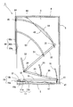
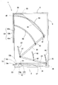
- a fall prevention device (hereinafter referred to as a fall prevention device) according to the best mode for carrying out the present invention will be described in detail with reference to the drawings.
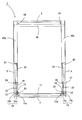
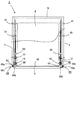
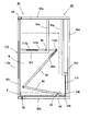
- the fall prevention device 1 includes a bottom plate 2 formed in a square shape, and a left side plate 3 that stands up from the left end of the bottom plate 2.
- 4 is provided with a back plate 5 connected to the back side end of 4 and a top plate 6 facing the bottom plate 2.
- the left side plate 3, the right side plate 4, the back plate 5 and the top plate 6 are all made of a metal plate formed into a square shape.
- the 1st left spindle holding member 11 is fixed to the front side middle part of the left side of the said baseplate 2 as shown in FIG.1 or FIG.2, and this baseplate is shown in FIG.1 or FIG.3.
- a first right support shaft holding member 12 is fixed to the front right halfway portion 2.
- the first left support shaft holding member 11 and the first right support shaft holding member 12 are respectively formed on base portions 11a and 12a fixed to the upper surface of the bottom plate 2 and on the upper portions of the base portions 11a and 12a.
- support shaft holding portions 11b, 12b having shaft insertion holes (reference numerals omitted) formed in the left-right direction, and the support shaft holding portion 11b of the left support shaft holding member 11 is The left support shaft 13 is inserted.
- the right support shaft 14 is inserted into the support shaft holding portion 12 b of the first right support shaft holding member 12.
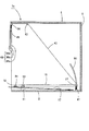
- a left rotating rod 15 is attached to the left support shaft 13.
- the left rotation rod 15 has a length from the front side to the back side of the overturn prevention device 1, and the first support shaft 13 is inserted in the middle of the front side.
- Left insertion hole 15a is formed, and a second left insertion hole 15b is formed further on the front side (front end side) than the position where the first left insertion hole 15a is formed.
- a right turning rod 16 is attached to the right support shaft 14.
- the right turning rod 16 is formed in the same shape as the left turning rod 15 and the first right insertion hole 16a through which the right support shaft 14 is inserted is inserted in the middle part on the front side.
- a second right insertion hole 16b is formed further on the front side (front end side) than the position where the first right insertion hole 16a is formed.
- the left pivot rod 15 is pivotally supported with the left pivot shaft 13 (fulcrum) as a pivot center, and the right pivot rod 16 pivots the right pivot shaft 14 (fulcrum).
- the front side end (power point) of the left turning rod 15 the rear side end (rear end) of the left turning rod 15 is supported.
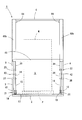
- a load supporting member 17 for supporting the load of the placed object is disposed on the bottom plate 2.
- the load support member 17 is formed to have a length and width slightly narrower than the length and width of the bottom plate 2.
- the front side end (front end) is As shown in FIG. 2 or FIG. 3, the bottom plate 2 projects slightly forward from the front side end (front end). Further, the rear side end (rear end) of the load support member 17 is supported and abutted on the bottom plate 2.
- a second left support shaft holding member 18 is attached to the left end of the load support member 17 on the front side, and a second right support holding member 19 is attached to the right side of the front side. Is fixed.
- the second left support shaft holding member 18 and the second right support shaft holding member 19 are formed on base portions 18a and 19a whose bottom surfaces are fixed to the bottom plate 2, and on the upper portions of the base portions 18a and 19a. And support shaft holding portions 18b and 19b with shaft insertion holes (reference numerals omitted) formed in the left-right direction.
- the left rotation shaft 21 is inserted.
- the right rotation shaft 22 is inserted into the support shaft holding portion 19 b of the second right support shaft holding member 19.
- the left rotation shaft 21 is inserted into a second left insertion hole 15b formed in the left rotation rod 15, and the right rotation shaft 22 is As shown in FIG. 2, the second right insertion hole 16b formed in the right turning rod 16 is inserted. That is, the left side of the front side of the load support member 17 is rotatably supported and connected via the left rotation shaft 21, and the right side of the front side of the load support member 17 is the right rotation shaft. Via 22, it is supported and connected to be rotatable. Therefore, as will be described later, when an object is placed on the load support member 17, the load support member 17 moves downward while rotating around the left rotation shaft 21 and the right rotation shaft 22. Eventually, the lower surface abuts on the upper surface of the bottom plate 2.
- one end of the first left link member 28 is connected to the first end of the first left link member 28 via the first left link side convex portion 27 as shown in FIG.
- the left link side convex portion 27 is connected to be rotatable.
- one end of the second left link member 30 is connected to the second left link side convex portion 29 via the second left link side convex portion 29 at the other end of the first left link member 28. It is pivotally connected to the center.
- a third left link-side convex portion 31 is formed in the middle portion of the second left link member 30 at the other end side, and a fourth left link member 30 is formed at the other end of the second left link member 30.
- a link-side convex portion 32 is formed.
- a fifth left link side convex portion 33 is further formed in the middle portion of the first left link member 28.
- the first to fifth left link side convex portions 27, 29, 31, 32, 33 all have a length in the thickness direction of the left side plate 3.
- one end of the first right link member 36 is connected to the first end of the first right link member 36 via the first right link side convex portion 35, as shown in FIG.
- the right link side convex portion 35 is connected to be rotatable.
- one end of the second right link member 38 is connected to the second right link side convex portion 37 via the second right link side convex portion 37 at the other end of the first right link member 36. It is pivotally connected to the center.
- the second right link member 38 has a third right link side convex portion 40 formed in the middle of the other end side, and the other end of the second right link member 38 has a fourth right side.
- a link-side convex portion 41 is formed.
- a fifth right link side convex portion 42 is further formed in the middle portion of the first right link member 36.
- the first to fifth right link side convex portions 35, 37, 40, 41, 42 all have a length in the thickness direction of the right side plate 4.
- the left linear body 43 is connected to the other end of the second left link member 30, and the other end of the second right link member 38 is connected to FIG.
- one end of the right linear body 44 is connected.
- the left linear body 43 and the right linear body 44 are each composed of a flexible linear body such as a chain or a wire, and the other ends of the left linear body 43 and the right linear body 44.
- the overturn prevention member 45 is fixed to the left end side and the right end side of the overturn prevention member 45 that moves up and down on the front side of the left side plate 3 and the right side plate 4.
- the fall prevention member 45 is a rod-like body having a length in the horizontal direction.
- the lower end of the left elastic member 47 is fixed to the rear end side of the left side of the bottom plate 2, and the upper end of the left elastic member 47 is connected to the rear end of the left rotating rod 15. It is locked.
- the lower end of the right elastic member 48 is fixed to the rear end side of the right side of the bottom plate 2, and the upper end of the right elastic member 48 is connected to the rear end of the right rotating rod 16. It is locked.
- the left elastic member 47 and the right elastic member 48 are constituted by (pulling) coil springs in the overturn prevention device 1 according to the present embodiment. The rear end side of 16 is urged downward (in the direction of the bottom plate 2).
- first to fifth left link side convex portions 27, 29, 31, 32, 33 are inserted into the left side plate 3, and the first left link member 28 and the second left link member 30 are inserted.
- the first to fifth left guide grooves 51... 55 corresponding to the trajectory of the moving operation are formed in an arc shape.
- first to fifth right link side convex portions 35, 37, 40, 41, 42 are inserted into the right side plate 4, and the first right link member 36 and the second right link member 38 are inserted.
- the first to fifth right guide grooves 56... 60 corresponding to the trajectory of the moving operation are formed in an arc shape.
- the first left linear body guide member 63 and the first right linear body guide member 65 are disposed slightly rearward from the front surfaces (front ends) of the left side plate 3 and the right side plate 4, respectively.
- the left linear body guide member 64 and the second right linear body guide member 66 are disposed in the vicinity of the front surface of the left side plate 3 and the right side plate 4, respectively.
- a left lifting guide member 68 whose planar shape is formed in a U shape is fixed to the front surface of the left side plate 3, and a flat surface is provided to the front side of the right side plate 4.
- a right elevating guide member 69 having a U shape is fixed.
- the left elevating guide member 68 and the right elevating guide member 69 are respectively fixed plate portions 68a and 69a fixed to the front surface of the left side plate 3 or the right side plate 4, and the rear surface faces the front surface of the fixed plate portions 68a and 69a.
- the front plate portions 68c and 69c that are opposed to each other and the outer plate portions 68c and 69c that are flush with the outer surface of the left side plate 3 or the right side plate 4 are arranged on the right side of the left lifting guide member 68. Is opened, and the left side of the right elevating guide member 69 is open. The left end side of the tipping prevention member 45 described above is inserted into the left lifting guide member 68, and the right end side of the tipping prevention member 45 is inserted into the right lifting guide member 69. Note that the lower ends of the left elevating guide member 68 and the right elevating guide member 69 are positioned in the vicinity of the intermediate position of the left side plate 3 or the right side plate 5, respectively.
- the front plate portions 68b and 69b are position holding means that constitute the present invention.
- the fall-preventing device 1 has the above-described fall-preventing member 45 at the uppermost position as shown in FIG. 2, FIG. 3 or FIG. Further, the front end (front side end portion) of the load support member 17 is spaced above the upper surface of the bottom plate 2, and the rear end (back side end portion) thereof is the bottom plate 2. It is in contact with the upper surface of the surface and slightly inclined as a whole. Further, the left turning rod 15 and the right turning rod 16 also have their front ends (front end portions) spaced above the upper surface of the bottom plate 2 and are slightly inclined as a whole.
- the state of the fall prevention member 45, the load support member 17, the left turning rod 15, the right turning rod 16 and the like shown in FIG. 2 or FIG. the pallet P on which the above-mentioned figurine W is placed is supported by left and right forks (not shown) and driven by the forklift, the left plate 2 and the right plate 3 are moved.
- the pallet P is moved down into the toppling prevention device 1 and then gradually lowered, the load of the pallet P and the object W is gradually supported by the load support member 17 and the load support member. 17 moves downward, and eventually the lower surface thereof comes into contact with the upper surface of the bottom plate 2.
- the left pivot rod 15 is guided by the first left guide groove 51 while the left pivot shaft 13 is the pivot center, and the right pivot rod 2 and 3 in FIG. 2 or FIG. 3 against the elastic force of the left elastic member 47 or the right elastic member 48 with the right support shaft 14 as the center of rotation while being guided by the first right guide groove 56.
- the first left link member 28 is pulled by the weight of the fall prevention member 45 while the second and second link members 28 are pulled.
- the first right link member 36 moves while being guided by the fifth left guide grooves 52 and 55, and the second and fifth right guides 36 are pulled while being pulled by the weight of the fall prevention member 45. It moves while being guided by the grooves 57 and 60, respectively.
- the second left link member 30 and the second right link member 38 are moved together with the first movement.
- the fall prevention member 45 moves from the standby position to the left lifting guide.
- the lower end position of the left elevating guide member 68 and the right elevating guide member 69 (the front of the object to be placed) is lowered while being guided by the member 68 and the right elevating guide member 69. And a position where the insertion space S into which the fork can be inserted is left (see FIG. 7).
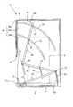
- the fork is inserted from the insertion space S formed below the fall-preventing member 45. Is inserted into the pallet P and the forklift is driven to raise (lift) the pallet P. As the pallet P is raised, the load support member 17, the left rotating rod 15 and the right rotating rod 16 are returned to the standby state by the elastic force of the left elastic member 47 and the right elastic member 48, respectively.
- the first and second left link members 28 and 30 and the first and second right link members 38 and 38 also operate in the direction opposite to the above-described rotation operation. By the operation, the fall prevention member 45 also returns to the standby state. Therefore, by driving the forklift, the pallet P on which the above-mentioned figurine W is placed can be taken out from the fall prevention device 1 to the outside.
- the fall prevention device 1 does not use any configuration that is electrically driven as a configuration of the device that prevents the placed object from falling and falling due to vibration such as an earthquake. Therefore, even if a power outage occurs due to the occurrence of the earthquake or the like, it can function without fail. Further, in the fall prevention device 1, the first turning rod 15 that turns in the same manner as a lever and the left linear body 43 connected to the left end side of the fall prevention member 45 are between the first linear body 43. And the second left link members 28 and 30 are interposed between the right linear rod 44 and the right linear body 44 connected to the right end side of the fall prevention member 45.
- the left rotation rod 15 and the right rotation rod 16 are located on the front side of the left rotation rod 15 and the right rotation rod 16 (front end side middle portion). ), The left support shaft 13 or the right support shaft 14 pivoted at the center of rotation, and the load support member 17 or the left rotation rod 15 or the right rotation rod 16 from the position of the front end of the force support point. It is an action point from the left support shaft 13 or the right support shaft 14 that is the fulcrum than the distance to the left support shaft 13 or the right support shaft 14. Since the distance to the rear end position of the left rotation rod 15 and the right rotation rod 16 is much longer, the fall prevention member 45 is moved up and down over a distance considerably longer than the distance by which the load support member 17 descends. Can be made.
- the first and second left link members 28 and 30 and the first and second right link members 36 and 38 are constituent elements.
- the rear end side of the left rotating rod 15 and the left linear body 43 may be directly connected, and the right rotating rod 16 and the right linear body 44 may be directly connected (not shown).
- the up / down range of the fall prevention member 45 is shorter than that of the fall prevention device 1 according to the embodiment described above, but the load of the mounted object W is reduced. By being supported by the load support member 17, the fall prevention member 45 can be moved up and down over a distance longer than the distance by which the load support member 17 descends.
- a fall prevention member constituting the present invention a rod-shaped body (fall over prevention member 45) having a length in the horizontal direction is illustrated and described.
- the fall-preventing member constituting the above invention may be not only a rod-like body but also a plate-like body.
- a rod-like body having a length in the horizontal direction such as an insulator is connected to be freely rotatable up and down. And is configured to be guided by the second left linear body guide member 64 and the second right linear body guide member 66 while being bent by being raised and partially bent on the upper end side. Also good.
- the plate body (load support member 17) formed in a square shape is illustrated and described as the load support member constituting the present invention.
- the load supporting member constituting the invention may be, for example, a rod-shaped body, a wire or belt stretched in the horizontal direction, etc., as long as it supports at least all or a part of the load of the mounted object. good.
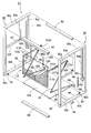
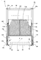
- the fall prevention device 81 has a left frame 82 and a right frame 83 which are each formed into a frame shape by a hollow steel frame and are formed in the same shape, and the left frame 82 and the right frame.
- Four horizontal rods 84 connecting the frame 83 are provided.
- the left frame 82 includes an upper left rod 82a and a lower left rod 82b that are formed to be the same length and parallel to each other, and a left front rod 82c and a left rear rod 82d that are formed to be the same length and are parallel to each other.
- the right frame 83 includes an upper right collar 83a and a lower right collar 83b, a right front collar 83c, and a right rear collar 83d.
- the first left vertical rod 82e hangs down slightly from the center of the lower surface of the upper left rod 82a constituting the left frame 82, and from slightly above the center of the rear surface of the left front rod 82c.
- a left parallel rod (a left stopper constituting the present invention) 82f which is parallel to the upper left rod 82a and fixed at the lower end of the first left vertical rod 82e, is fixed, and the first left vertical rod 82e
- a left fixed rotation shaft 87 is erected in the horizontal direction at a position fixed to the left parallel rod 82f.
- a second left vertical rod 82g that is parallel to the left rear rod 82d is suspended from the lower surface of the middle portion of the rear left side of the upper left rod 82a, and the lower end of the second left vertical rod 82g
- a left connection rod 82h is connected to the front of the left rear rod 82d.
- the other left rotation shaft 89 projects from the right frame 83 side on the front end side of the inner surface of the lower left rod 82b constituting the left frame 82.
- a shaft support column 90 is erected in the middle of the rear end side of the upper surface of the lower left rod 82b.
- the left support shaft 91 constituting the present invention protrudes toward the right frame 83 on the shaft support column 90. It is installed.
- the first left vertical rod 82e, the left parallel rod 82f, the left fixed rotation shaft 87, the second left vertical rod 82g, the left connection rod 82h, and the other left rotation shaft 89 are also provided on the right frame 83.
- the first right vertical rod 83e, the right parallel rod 83f, the right fixed pivot shaft 88, the second right vertical rod 83g, and the right connection rod 83h formed in the same shape as the shaft support column 90 and the left support shaft 91.
- the other right rotation shaft 92 (see FIG. 11), a shaft support column 94, and a right support shaft 93 are provided.
- the right parallel rod 83f is a right stopper constituting the present invention.
- the left support shaft 91 is rotatably attached with a left turning rod 95 constituting the present invention.
- the right support shaft 93 is rotatably attached with a right turning rod 96 constituting the present invention.
- An insertion shaft (reference numeral is omitted) through which the left support shaft 91 is inserted is formed in the middle part on the rear end side of the left rotating rod 95, and a connecting shaft (reference numeral is omitted) is formed at the front end.
- one end of the left link member 98 is rotatably connected.
- an insertion shaft (reference numeral is omitted) through which the right support shaft 93 is inserted is formed in the middle part of the right rotation rod 96 on the rear end side, and a connecting shaft (reference numeral is omitted) at the front end.
- One end of the right link member 99 is rotatably connected through the. Long holes 98a and 99a are formed on the other end sides of the left link member 98 and the right link member 99, respectively.
- the load supporting member 101 constituting the present invention is disposed between the lower left rod 82b constituting the left frame 82 and the lower right rod 83b constituting the right frame 83.
- the load support member 101 is a plate formed in a rectangular shape, and supports the entire load of the object to be loaded as described later.
- the front of the left end (on the lower surface) of the load support member 101 is The other left rotation shaft 89 is rotatably supported, and the front of the right end is rotatably supported by the other right rotation shaft 92 (see FIG. 11).
- a left shaft support piece 102 is erected on the left side of the rear end of the load support member 101, and the left shaft is fixed to the left shaft 103 through one left rotation shaft 103 fixed to the upper end side of the left shaft support piece 102.
- the rear end of the rotary rod 95 is rotatably connected.
- a right shaft support piece 105 is provided upright on the left side of the rear end of the load support member 101, and the right shaft is supported via one right rotation shaft 106 fixed to the upper end side of the right shaft support piece 105.
- the rear end of the rotary rod 96 is rotatably connected.
- the fall prevention device 112 includes a fall prevention member 112 as a constituent element. As will be described later, the fall prevention member 112 includes a rectangular fall prevention member main body 112a (refer to FIG. 9 or FIG.
- the left arm 112b has a base end fixed to the left end of the back surface of the fall prevention member main body 112a, and a right arm 112c having a base end fixed to the right end of the back surface of the fall prevention member main body 112a.
- sliding shafts 112d and 112e inserted into elongated holes 98a and 99a formed on the other end side of the left link member 98 or the right link member 99 are provided at the distal ends of the left arm 112b and the right arm 112c. Is fixed.
- the fall prevention member main body 112a when the fall prevention member main body 112a is moved to the front of the object W placed on the load support member 101, The left contact member 112f and the right contact member 112g that contact the upper surface of the left parallel rod 92f or the right parallel rod 83f, which are the left stopper or the right stopper constituting the present invention, are fixed. Further, an insertion hole (not shown) through which the left fixed rotation shaft 87 is inserted is formed in the middle portion on the front end side of the left arm 112b, and the right fixed portion is formed in a middle portion on the front end side of the right arm 112c. An insertion hole (not shown) through which the rotation shaft 88 is inserted is formed. Therefore, as will be described later, the fall prevention member 112 is rotated around the left fixed rotation shaft 87 and the right fixed rotation shaft 88.
- the rear end side of the load support member 101 is slightly higher than the front end side, as shown in FIG. 10 or FIG.
- the fall prevention member main body 112a that constitutes the fall prevention member 112 is in a substantially horizontal state at the top.
- the sliding shaft 112d fixed to the left arm 112b is positioned at the lowermost part (one end side) of the long hole 98a formed in the left link member 98, and is fixed to the right arm 112c in the same manner.
- the sliding shaft 112e thus positioned is located at the lowermost (one end side) of the long hole 99a formed in the right link member 99 (see FIG. 10).
- the pallet P on which the above-described object W is placed is supported by left and right forks (not shown) and is moved into the object-containing space formed in the fall prevention device 1 by driving the forklift.
- the load support member 101 includes the left elastic member 99 and the right elastic member.
- the rear end side descends (rotates) about the other left rotation shaft 89 and the other right rotation shaft 92 against the elastic force of the member 110.
- the left rotating rod 95 has the left supporting shaft 91 as a rotation center
- the right rotating rod 96 has the right rotating shaft. It rotates in the clockwise direction in FIG.
- the left turning rod 95 is turned
- the left link member 98 is lifted while having one end side as a turning center, and pushes up the left arm 112b constituting the fall prevention member 112.
- the right pivot rod 96 is pivoted, the right link member 99 rises with one end thereof as the pivot center and pushes up the right arm 112c constituting the fall prevention member 112.
- the entire fall prevention member 112 pushed up by the left link member 98 and the right link member 99 is centered on the left fixed rotation shaft 87 and the right fixed rotation shaft 88 in FIG. It rotates in the counterclockwise direction and eventually stops at the position shown in FIG.
- This state is a fall prevention state after the placing object W (and the pallet P) is placed on the load support member 101.
- the left contact member 112f is The right abutting member 112g abuts on the right-side transition bar 83f.
- the sliding shaft 112d fixed to the left arm 112b is located on the most other end side of the long hole 98a formed in the left link member 98, and is fixed to the right arm 112c in the same manner.
- the sliding shaft 112e is located on the most other end side of the long hole 99a formed in the right link member 99 (see FIG. 12). Therefore, even if a force is applied downward to the fall prevention member 112, the fall prevention member 112 will not be lowered any more, and the fall prevention member 112 will have the left fixed rotation shaft 87 and the right fixed rotation shaft 88. Therefore, even if the above-described figurine W comes into contact with the toppling prevention member main body 112a due to vibration such as an earthquake, there is no risk of further toppling.
- a fork of a forklift (not shown) that lifts the object W from above the load support member 101 is inserted from the front side below the fall prevention member main body 112. An insertion space S is formed (see FIG. 13).
- the configuration of the apparatus that prevents the mounted object from falling and falling due to vibration such as an earthquake is electrically Since it does not use any driving structure, it can function without fail even if a power failure occurs due to the occurrence of the earthquake or the like.
Landscapes
- Engineering & Computer Science (AREA)
- Mechanical Engineering (AREA)
- Warehouses Or Storage Devices (AREA)
- Handcart (AREA)
- Vibration Prevention Devices (AREA)
- Casings For Electric Apparatus (AREA)
Abstract
L'invention concerne un nouveau dispositif de prévention de renversement d'article, qui est apte à empêcher un article placé sur une carte de placement de tomber en raison de vibrations provenant de tremblements de terre etc., sans utiliser un élément quelconque actionné électriquement en tant que pièce. La présente invention comprend un élément de prévention de renversement (45) : qui possède une extrémité gauche reliée à une tige de rotation gauche (15) maintenue rotative sur une broche gauche (13) disposée à mi-chemin le long du côté d'extrémité avant ; qui possède une extrémité droite reliée à une tige de rotation droite (16) maintenue rotative sur une broche droite (14) disposée à mi-chemin le long du côté d'extrémité avant ou du côté d'extrémité arrière ; qui descend ou qui tourne en raison de la rotation de la tige de rotation gauche (15) et de la tige de rotation droite (16), lorsque la charge de l'article W est maintenue par un élément de support de charge (17) pour maintenir tout ou partie de la charge de l'article W ; et qui est positionné sur le côté avant de l'article W lorsque l'élément de prévention de renversement (45) est descendu à la position la plus basse. Lorsque l'élément de prévention de renversement (45) est descendu à la position la plus basse, un espace d'insertion, dans lequel un moyen de levage d'article est inséré depuis le côté de surface avant, est formé au-dessous.
Priority Applications (5)
| Application Number | Priority Date | Filing Date | Title |
|---|---|---|---|
| MX2019009807A MX2019009807A (es) | 2017-02-17 | 2018-02-14 | Dispositivo de prevencion de caidas. |
| KR1020197025855A KR102224091B1 (ko) | 2017-02-17 | 2018-02-14 | 재치물의 전도 방지 장치 |
| CN201880010671.2A CN110392658B (zh) | 2017-02-17 | 2018-02-14 | 物品防倾覆装置 |
| EP18754927.4A EP3597568A4 (fr) | 2017-02-17 | 2018-02-14 | Dispositif de prévention de renversement d'article |
| US16/486,027 US10709245B2 (en) | 2017-02-17 | 2018-02-14 | Article falling prevention device |
Applications Claiming Priority (2)
| Application Number | Priority Date | Filing Date | Title |
|---|---|---|---|
| JP2017-027761 | 2017-02-17 | ||
| JP2017027761A JP6544658B2 (ja) | 2017-02-17 | 2017-02-17 | 載置物の転倒防止装置 |
Publications (1)
| Publication Number | Publication Date |
|---|---|
| WO2018151120A1 true WO2018151120A1 (fr) | 2018-08-23 |
Family
ID=63169937
Family Applications (1)
| Application Number | Title | Priority Date | Filing Date |
|---|---|---|---|
| PCT/JP2018/004955 WO2018151120A1 (fr) | 2017-02-17 | 2018-02-14 | Dispositif de prévention de renversement d'article |
Country Status (7)
| Country | Link |
|---|---|
| US (1) | US10709245B2 (fr) |
| EP (1) | EP3597568A4 (fr) |
| JP (1) | JP6544658B2 (fr) |
| KR (1) | KR102224091B1 (fr) |
| CN (1) | CN110392658B (fr) |
| MX (1) | MX2019009807A (fr) |
| WO (1) | WO2018151120A1 (fr) |
Families Citing this family (3)
| Publication number | Priority date | Publication date | Assignee | Title |
|---|---|---|---|---|
| US10905912B2 (en) * | 2018-11-01 | 2021-02-02 | Tristan Thomas | Workout apparatus with telescoping legs |
| US11406190B2 (en) * | 2020-03-05 | 2022-08-09 | Direct Supply, Inc. | Recliner with extending stabilizer arms |
| US11805908B2 (en) * | 2020-03-05 | 2023-11-07 | Direct Supply, Inc. | Recliner with force-limited stabilizer arms |
Citations (6)
| Publication number | Priority date | Publication date | Assignee | Title |
|---|---|---|---|---|
| JPH1033289A (ja) * | 1996-07-23 | 1998-02-10 | Ohbayashi Corp | 収納棚の収納物落下防止装置 |
| JPH11178665A (ja) * | 1997-12-18 | 1999-07-06 | Itoki Crebio Corp | 棚什器の感震落下防止装置 |
| US5984121A (en) * | 1996-04-05 | 1999-11-16 | Carron Net Company, Inc. | Universal adjustable pallet rack safety system and offset bracket assembly |
| JP2010120750A (ja) * | 2008-11-20 | 2010-06-03 | Asaka Industrial Co Ltd | 棚の荷物落下防止装置 |
| JP2010273955A (ja) | 2009-05-29 | 2010-12-09 | Tokai Engineer:Kk | 収納物落下防止ユニット |
| JP2016069089A (ja) * | 2014-09-26 | 2016-05-09 | 株式会社ダイフク | ラックの荷落下防止装置 |
Family Cites Families (8)
| Publication number | Priority date | Publication date | Assignee | Title |
|---|---|---|---|---|
| JP3507029B2 (ja) * | 2000-11-22 | 2004-03-15 | 住友重機械工業株式会社 | 背面ピッキング式パレット自動倉庫の安全装置 |
| JP5093861B2 (ja) * | 2009-04-09 | 2012-12-12 | 金剛株式会社 | 収納棚 |
| JP2010254407A (ja) * | 2009-04-23 | 2010-11-11 | Cubic Shizuoka:Kk | 収納棚における収納物落下防止装置及び収納棚における収納物落下防止方法 |
| JP2011218118A (ja) * | 2010-04-07 | 2011-11-04 | Natsu Koopu:Kk | 半固定式転倒防止装置とその補助具 |
| EP2722552A4 (fr) * | 2011-06-17 | 2016-03-30 | Kikuo Sugita | Procédé pour prévenir le renversement d'un pylône |
| CN203080382U (zh) * | 2013-02-27 | 2013-07-24 | 王兆庆 | 混凝土伸缩缝板材的下压填充装置 |
| JP6349382B2 (ja) * | 2013-03-13 | 2018-06-27 | カティーバ, インコーポレイテッド | 補助エンクロージャを利用するガスエンクロージャシステムおよび方法 |
| CN104207491B (zh) * | 2014-09-03 | 2016-08-24 | 常州市武进南江图书文物用品有限公司 | 密集型防震文物存放柜 |
-
2017
- 2017-02-17 JP JP2017027761A patent/JP6544658B2/ja active Active
-
2018
- 2018-02-14 US US16/486,027 patent/US10709245B2/en active Active
- 2018-02-14 KR KR1020197025855A patent/KR102224091B1/ko active IP Right Grant
- 2018-02-14 MX MX2019009807A patent/MX2019009807A/es unknown
- 2018-02-14 WO PCT/JP2018/004955 patent/WO2018151120A1/fr unknown
- 2018-02-14 EP EP18754927.4A patent/EP3597568A4/fr active Pending
- 2018-02-14 CN CN201880010671.2A patent/CN110392658B/zh active Active
Patent Citations (6)
| Publication number | Priority date | Publication date | Assignee | Title |
|---|---|---|---|---|
| US5984121A (en) * | 1996-04-05 | 1999-11-16 | Carron Net Company, Inc. | Universal adjustable pallet rack safety system and offset bracket assembly |
| JPH1033289A (ja) * | 1996-07-23 | 1998-02-10 | Ohbayashi Corp | 収納棚の収納物落下防止装置 |
| JPH11178665A (ja) * | 1997-12-18 | 1999-07-06 | Itoki Crebio Corp | 棚什器の感震落下防止装置 |
| JP2010120750A (ja) * | 2008-11-20 | 2010-06-03 | Asaka Industrial Co Ltd | 棚の荷物落下防止装置 |
| JP2010273955A (ja) | 2009-05-29 | 2010-12-09 | Tokai Engineer:Kk | 収納物落下防止ユニット |
| JP2016069089A (ja) * | 2014-09-26 | 2016-05-09 | 株式会社ダイフク | ラックの荷落下防止装置 |
Non-Patent Citations (1)
| Title |
|---|
| See also references of EP3597568A4 * |
Also Published As
| Publication number | Publication date |
|---|---|
| US10709245B2 (en) | 2020-07-14 |
| EP3597568A4 (fr) | 2021-07-07 |
| KR102224091B1 (ko) | 2021-03-05 |
| JP6544658B2 (ja) | 2019-07-17 |
| CN110392658A (zh) | 2019-10-29 |
| JP2018131315A (ja) | 2018-08-23 |
| EP3597568A1 (fr) | 2020-01-22 |
| US20200046119A1 (en) | 2020-02-13 |
| KR20190111107A (ko) | 2019-10-01 |
| MX2019009807A (es) | 2019-10-09 |
| CN110392658B (zh) | 2021-06-11 |
Similar Documents
| Publication | Publication Date | Title |
|---|---|---|
| WO2018151120A1 (fr) | Dispositif de prévention de renversement d'article | |
| JP5681412B2 (ja) | 板状部材収納用ラック、板状部材移載設備、及び板状部材収納方法 | |
| JP2010149885A (ja) | パレット | |
| JP2006240884A (ja) | 長尺物品用荷役装置 | |
| JP2019116385A (ja) | 載置物の転倒防止装置 | |
| JP5024337B2 (ja) | 搬送システム及び保管装置 | |
| JP2018131315A5 (fr) | ||
| JP2015185516A (ja) | 布線作業用装置 | |
| JP2006016190A (ja) | 物流用棚装置 | |
| JP4487319B2 (ja) | 位置決め装置とそれを用いた載置台 | |
| JP4585775B2 (ja) | 昇降装置 | |
| JP5949636B2 (ja) | 物品収納棚 | |
| JP3196532U (ja) | 折畳み架台 | |
| JP6941033B2 (ja) | 可動ラック及び可動ラック台車 | |
| JP2006282304A (ja) | 移載装置 | |
| JP3600190B2 (ja) | 収納部用昇降支持ユニットおよびこれを用いた昇降収納装置 | |
| JP5060333B2 (ja) | 駐車装置 | |
| JP3315396B2 (ja) | 収納部用昇降支持ユニットおよびこれを用いた昇降収納装置 | |
| JP6557837B2 (ja) | 落下防止装置、及び、棚 | |
| JP2004035192A (ja) | 長尺物保管用可動棚 | |
| JP2016216150A (ja) | フォークリフト用アタッチメント | |
| JP5203999B2 (ja) | フロントフォークアッセンブリ組立方法 | |
| CA3113285A1 (fr) | Appareil de commande pour le stockage et le destockage de marchandises au detail en forme de bouteilles | |
| JP2021004126A (ja) | サヤフォーク着脱装置 | |
| JP2001178561A (ja) | 収納部用昇降支持ユニットおよびこれを用いた昇降収納装置 |
Legal Events
| Date | Code | Title | Description |
|---|---|---|---|
| 121 | Ep: the epo has been informed by wipo that ep was designated in this application |
Ref document number: 18754927 Country of ref document: EP Kind code of ref document: A1 |
|
| NENP | Non-entry into the national phase |
Ref country code: DE |
|
| ENP | Entry into the national phase |
Ref document number: 20197025855 Country of ref document: KR Kind code of ref document: A |
|
| ENP | Entry into the national phase |
Ref document number: 2018754927 Country of ref document: EP Effective date: 20190917 |