WO2018151120A1 - Article overturn prevention device - Google Patents
Article overturn prevention device Download PDFInfo
- Publication number
- WO2018151120A1 WO2018151120A1 PCT/JP2018/004955 JP2018004955W WO2018151120A1 WO 2018151120 A1 WO2018151120 A1 WO 2018151120A1 JP 2018004955 W JP2018004955 W JP 2018004955W WO 2018151120 A1 WO2018151120 A1 WO 2018151120A1
- Authority
- WO
- WIPO (PCT)
- Prior art keywords
- fall prevention
- link
- end side
- rod
- rear end
- Prior art date
Links
Images


Classifications
-
- B—PERFORMING OPERATIONS; TRANSPORTING
- B65—CONVEYING; PACKING; STORING; HANDLING THIN OR FILAMENTARY MATERIAL
- B65G—TRANSPORT OR STORAGE DEVICES, e.g. CONVEYORS FOR LOADING OR TIPPING, SHOP CONVEYOR SYSTEMS OR PNEUMATIC TUBE CONVEYORS
- B65G1/00—Storing articles, individually or in orderly arrangement, in warehouses or magazines
- B65G1/02—Storage devices
-
- A—HUMAN NECESSITIES
- A47—FURNITURE; DOMESTIC ARTICLES OR APPLIANCES; COFFEE MILLS; SPICE MILLS; SUCTION CLEANERS IN GENERAL
- A47B—TABLES; DESKS; OFFICE FURNITURE; CABINETS; DRAWERS; GENERAL DETAILS OF FURNITURE
- A47B97/00—Furniture or accessories for furniture, not provided for in other groups of this subclass
-
- A—HUMAN NECESSITIES
- A47—FURNITURE; DOMESTIC ARTICLES OR APPLIANCES; COFFEE MILLS; SPICE MILLS; SUCTION CLEANERS IN GENERAL
- A47B—TABLES; DESKS; OFFICE FURNITURE; CABINETS; DRAWERS; GENERAL DETAILS OF FURNITURE
- A47B96/00—Details of cabinets, racks or shelf units not covered by a single one of groups A47B43/00 - A47B95/00; General details of furniture
-
- B—PERFORMING OPERATIONS; TRANSPORTING
- B65—CONVEYING; PACKING; STORING; HANDLING THIN OR FILAMENTARY MATERIAL
- B65G—TRANSPORT OR STORAGE DEVICES, e.g. CONVEYORS FOR LOADING OR TIPPING, SHOP CONVEYOR SYSTEMS OR PNEUMATIC TUBE CONVEYORS
- B65G1/00—Storing articles, individually or in orderly arrangement, in warehouses or magazines
- B65G1/02—Storage devices
- B65G1/14—Stack holders or separators
-
- A—HUMAN NECESSITIES
- A47—FURNITURE; DOMESTIC ARTICLES OR APPLIANCES; COFFEE MILLS; SPICE MILLS; SUCTION CLEANERS IN GENERAL
- A47B—TABLES; DESKS; OFFICE FURNITURE; CABINETS; DRAWERS; GENERAL DETAILS OF FURNITURE
- A47B97/00—Furniture or accessories for furniture, not provided for in other groups of this subclass
- A47B2097/008—Anti-tip devices
-
- B—PERFORMING OPERATIONS; TRANSPORTING
- B65—CONVEYING; PACKING; STORING; HANDLING THIN OR FILAMENTARY MATERIAL
- B65G—TRANSPORT OR STORAGE DEVICES, e.g. CONVEYORS FOR LOADING OR TIPPING, SHOP CONVEYOR SYSTEMS OR PNEUMATIC TUBE CONVEYORS
- B65G2207/00—Indexing codes relating to constructional details, configuration and additional features of a handling device, e.g. Conveyors
- B65G2207/20—Earthquake protection
-
- B—PERFORMING OPERATIONS; TRANSPORTING
- B65—CONVEYING; PACKING; STORING; HANDLING THIN OR FILAMENTARY MATERIAL
- B65G—TRANSPORT OR STORAGE DEVICES, e.g. CONVEYORS FOR LOADING OR TIPPING, SHOP CONVEYOR SYSTEMS OR PNEUMATIC TUBE CONVEYORS
- B65G2207/00—Indexing codes relating to constructional details, configuration and additional features of a handling device, e.g. Conveyors
- B65G2207/40—Safety features of loads, equipment or persons
Definitions
- the present invention is to prevent a product or part mounted on a mounting plate such as a shelf, rack or cabinet from falling or dropping from the mounting plate due to vibration such as an earthquake. It is related with the fall prevention apparatus of the mounted material used for.
- JP 2010-273955 A Patent Document 1
- the stored item fall prevention unit disclosed in this publication is such that the fall prevention arm descends from a standby state by driving an actuator that operates in response to a signal from a seismometer that detects vibration due to an earthquake.
- the stored item fall prevention unit disclosed in Patent Document 1 the stored item does not fall by coming into contact with the fall preventing arm that has been lowered due to the occurrence of an earthquake.
- the seismometer and the actuator are constituent elements, and these operate electrically, so that not only a power source is necessarily required but also a power failure due to an earthquake. Does not work.
- the present invention has been proposed to solve the above-described problems of the prior art, and does not include any electrically operated member at all, and is placed by vibration such as an earthquake. It is an object of the present invention to provide a novel device for preventing a fall of a placed object that can prevent the placed object from falling.
- the present invention has been proposed in order to solve the above-mentioned problems.
- the front side is released and the placed object is accommodated inside.
- a right rotating rod that is arranged to be rotatable about a right support shaft having a length, and a left end is connected to a front end side or a rear end side of the left rotating rod, and a right end is the right rotating rod.
- a load support member connected to the front end side or the rear end side and supporting all or part of the load of the figurine described above, and the front end side or the rear end side of the load support member, or the left rotation rod or the right rotation
- An elastic member that is urged so that the front end side or the rear end side of the bag is always positioned upward, and the load support In the standby state before the placement object is placed on the material, it stands by at a standby position that is above or obliquely above the load support member, and falls after the placement object is placed on the load support member
- a fall prevention member that moves from the standby position to the front side of the placement object, and the left support shaft is rotated counterclockwise at either the front end side or the rear end side of the left rotation rod.
- the right support shaft supports the right rotation shaft on either the front end side or the rear end side of the right rotation shaft, and the left end of the fall prevention member and the left rotation
- the scissors are connected to each other by a linear connecting material made of a linear body, a link connecting material made of a single or a plurality of link members, or a composite connecting material made of the linear body and a plurality of link members,
- the right end of the fall prevention member and the right turning rod are linearly connected with a linear body.
- an insertion space is formed below the anti-falling member into which the object lifting means constituting the fork of the forklift or other machine or apparatus for lifting the object from above the load support member is inserted from the front side. It is characterized by.
- the device for preventing overturning of the mounted object is formed with a mounted object storage space in which the mounted object is stored inside while the front side is released.
- the member forming the accommodation space may be a left side plate or a right side plate (refer to the invention described in claim 2), or a left frame or a right frame (claim 8). (See invention of the present invention).
- the left rotation rod and the right rotation rod are provided.
- the left rotation rod and the right rotation rod are rotatable about a left or right support shaft having a length in the horizontal direction.
- the left support shaft supports the left rotation shaft at either the front end side or the rear end side of the left rotation shaft, and the right support shaft supports the front end side or the rear end of the right rotation shaft.
- the right turning rod is pivotally supported on either one of the sides.
- the load support member is a component, and the load support member has a left end connected to the left rotation rod and a right end connected to the right rotation rod. It supports all or part of the load. Therefore, the left support shaft pivotally supports the left rotation rod on the front end side of the left rotation rod, the right support shaft pivotally supports the right rotation rod on the front end side of the right rotation rod, In addition, when the left end of the load support member is connected to the front end side of the left rotation rod and the right end of the load support member is connected to the front end side of the right rotation rod, the load support member is mounted on the load support member.
- the rear ends of the left rotating rod and the right rotating rod are larger than the lengths at which the front ends of the left rotating rod and the right rotating rod are lowered.
- the left support shaft pivotally supports the left rotation rod at the rear end side of the left rotation rod
- the right support shaft pivots the right rotation rod at the rear end side of the right rotation rod.
- this load support member should just support at least one part of the load of a mounting object, and the shape and area are not specifically limited.
- most of the load of the mounted object is supported by the bottom plate, and a part of the load may be a bar arranged horizontally so as to be supported by the load supporting member, or the entire mounted object may be mounted. It may be configured by a plate body to be placed.
- the elastic member is a constituent element.
- This elastic member may be urged so that the front end side or the rear end side of the load supporting member is always positioned upward, or the front end side of the left rotating rod or the right rotating rod or The rear end side may be urged so as to be always positioned upward.
- the elastic member is an elastic member that urges the left rotating rod when the front rotating end or the rear rotating end of the right rotating rod is always positioned upward.
- the elastic member that urges the right rotating rod may be disposed separately.
- the members are not limited to those disposed below the load support member, the left pivot rod, or the right pivot rod, but may be disposed above them.
- the shape of the elastic member may be a string spring or a leaf spring.
- the fall prevention member is a constituent element.
- the fall prevention member In the standby state before the placing object is placed on the load support member, the fall prevention member stands by at a standby position that is above or obliquely above the load support member, and is placed on the load support member.
- the object In the fall prevention state after the object is placed, the object moves from the standby position to the front side of the object.
- the left end of this fall prevention member and the above-mentioned left rotation rod are a linear connecting material consisting of a linear body, a link connecting material consisting of a single or a plurality of link members, or the above linear body and a plurality of links
- the right end of the fall-preventing member and the right pivot rod are composed of a linear coupling material composed of a linear body, or a single or a plurality of link members. It is mutually connected by the link connection material or the composite connection material which consists of the said linear body and a some link member. Therefore, according to the present invention, when an object is placed on the load support member, the fall prevention member is in the standby state via the linear connecting member, the link connecting member, or the composite connecting member. To the fall prevention state.
- the forelift lifting means constituting the fork or other machine or device of the forklift for lifting the placement from the load support member is in front.
- An insertion space to be inserted from the side is formed below the fall prevention member.
- the fall prevention device for a placement object when all or a part of the load of the placement object is supported by the load support member by the above-described object lifting means, the elastic force of the elastic member is reduced.
- the left rotating rod rotates about the left supporting shaft
- the right rotating shaft rotates about the right supporting shaft.
- the rear end side or the front end side of the right rotating rod rises over a distance longer than the distance by which the load supporting member descends, and the rotation of the left rotating rod and the right rotating rod and the linear shape
- the above-mentioned figurine lifting means can be moved outside in the state which left the above-mentioned figurine left. it can. In this state, when the above-described figurine is tilted in a direction to fall due to vibration such as an earthquake, the placed article comes into contact with the fall-preventing member and is prevented from falling.
- the load is supported by the load support member by vibration such as an earthquake without using any electrically operated member as a constituent element and only by a mechanical structure. It is possible to prevent the placed object from falling, and it is possible to reliably prevent the placed object from falling even when a power failure occurs due to the occurrence of an earthquake or the like.
- the above-mentioned figurine accommodation space includes a bottom plate, a left side plate standing on the left side of the bottom plate, and a right side of the bottom plate. And the right side plate that faces the left side plate, and the load supporting member is disposed above the bottom plate, and the load supporting member is made to be elastic by the load of the mounted object. When it descends against the elastic force, it comes into contact with the upper surface of the bottom plate.
- the load is supported by vibration such as an earthquake without using any electrically operated member as a constituent element. It is possible not only to prevent the mounted object whose load is supported by the member from falling, but also to reliably prevent the mounted object from falling even if a power failure occurs due to the occurrence of an earthquake or the like.
- the load support member comes into contact with the upper surface of the bottom plate, so that the placement portion can be placed in a more stable state.
- the invention according to a third aspect is that, in the second aspect, the overturn prevention member is positioned on an upper end side on a front end side of the left side plate and the right side plate in the standby state. In the fall prevention state, it is located in the middle part of the front end side of the left side plate and the right side plate and is located on the front side of the above-mentioned figurine, and on the front side of the left side plate and the right side plate, Position holding means for holding the position of the fall prevention member when the above-mentioned figurine abuts on the back surface is disposed, and the left end of the fall prevention member and the left rotation rod are the linear connecting members Connected to the end of the linear body constituting the composite connecting member, and the right end of the overturn prevention member and the right rotation rod are the linear Connected by a linear body constituting the connecting material, or the composite When the placing object is placed on the load support member and connected to the end of the linear body constituting the general connecting member, the left turning rod turns around the
- both the left and right ends of the fall prevention member are suspended by the linear body, and the fall prevention member descends when the object to be placed is placed on the load support member.
- the load is raised and the standby state is reached. That is, according to the third aspect of the present invention, the fall prevention member can be raised and lowered, and when the fall prevention member descends to reach the above-described fall prevention state, an earthquake or the like occurs and the mounted article falls to prevent the fall.
- the position holding means holds the position of the fall prevention member.
- a left guide plate facing the front surface is provided on the front side of the left side plate, and the inside of the left guide plate forms a left guide space, and the front side of the right side plate
- a right guide plate facing the front is provided on the inner side of the right guide plate so that the inner side of the right guide plate serves as a right guide space, the left end side of the fall prevention member is disposed in the left guide space, and the right end side of the fall prevention member Is placed in the right guide space, and the above-mentioned figurine comes into contact with the fall prevention member, the left end side of the fall prevention member comes into contact with the back surface of the left guide plate and the right end side of the fall prevention member
- the fall prevention member may hold the position.
- 4th invention is either the said 1st, 2nd or 3rd invention
- the left end of the said fall prevention member and the said left rotation rod are said composite connection.
- the right end of the fall prevention member and the right turning rod are connected to each other by the composite connecting material, and the rear end of the left turning rod is connected to the composite connection.
- One end of the first left link member constituting the member is rotatably connected, and the other end of the first left link member is connected to one end of the second left link member constituting the composite connecting member.
- the other end of the second left link member is movably connected, and the one end of the left linear body is fixed to the other end of the second link member and the middle portion is guided by the linear body guide member.
- the other end of the left linear body is fixed to the left end of the fall prevention member, and the rear end of the right rotating rod is One end of the first right link member constituting the general connecting member is rotatably connected, and the other end of the first right link member is connected to one end of the second right link member constituting the composite connecting member.
- One end of the first right link member constituting the general connecting member is rotatably connected, and the other end of the first right link member is connected to one end of the second right link member constituting the composite connecting member.
- the other end of the right linear body is fixed to the other end of the second right link member and the middle portion is guided by the linear body guide member.
- the other end of the right linear body is fixed to the right end of the fall-preventing member, and when the placing object is placed on the load supporting member, the left turning rod turns around the left support shaft.
- the right rotation rod rotates about the right support shaft, and the fall prevention member descends to reach the fall prevention state through the operation of the composite connecting member. Is.
- the device for preventing a fall of the mounted article wherein the left turn rod or the right turn kite and the fall prevention member are connected by the composite connecting material.
- link members to be configured first and second left link members and first and second right link members are used as components.
- the rear end or the rear end side midway portion of the left rotating rod has the A left convex portion protruding in the direction of the left side plate is formed, and a left guide groove corresponding to a movement locus in which the left convex portion is inserted and the left convex portion moves is formed on the left side plate, A right convex portion protruding in the direction of the right side plate is formed at the rear end or rear end side middle portion of the rotary rod, and the right convex portion is inserted into the right side plate, and the right convex portion is A right guide groove corresponding to the moving trajectory is formed, and the left rotating rod is guided by the left guide groove, and the right rotating rod is guided by the right guide groove, respectively. It is characterized by doing.
- the left turning rod is in the left guide groove through the left convex portion
- the right turning rod is in the above through the right convex portion. Since it rotates while being guided by the right guide groove, the counterclockwise rotation associated with the load of the above-mentioned object being supported by the load support member or the removal of the object from the load support member.
- the rotating operation of the moving rod and the right rotating rod can be made smooth, and as a result, the above-described overturn prevention member can be moved up and down smoothly.
- the left and right turning rods constituting the present invention may be arranged not only on the outside of the left side plate or the right side plate but also on the inside.
- the left convex part is not only inserted from the outside of the left side plate to the inside, but also when the left pivot is placed inside the left side plate, it is inserted from the inside of the left side plate to the outside. It may be.
- the right convex portion is not only inserted from the outside of the right side plate to the inside side, but also when the right turning rod is arranged inside the right side plate, from the inside of the right side plate. It may be inserted in the outward direction.
- the sixth invention (the invention according to claim 6) is the above-mentioned fourth invention,
- the end portions and / or midway portions of the first and second left link members are formed with left link-side convex portions protruding in the left-side plate direction, and the left-side plate includes the left link side
- the left link side guide groove corresponding to the movement trajectory along which the convex portion moves is formed, and the right link side protruding in the right plate direction at the end and / or midway of the first and second right link members
- a right link guide groove corresponding to a movement trajectory along which the right link side convex portion moves is formed on the right side plate, and the first and second left link members are formed.
- the mounting according to claim 4, wherein the first and second right link members rotate while being guided by the left link side guide groove, while being guided by the right link side guide groove.
- the first and second left link members are in the left link side guide groove, and the first and second right link members are in the right link. Since each of the side guide grooves rotates while being guided, the load of the above-mentioned object is supported by the load support member or the first and the second accompanying the lifting of the object from the load support member.
- the two left link members and the first and second right link members can be smoothly rotated, and the fall prevention member can be operated smoothly.
- the load supporting member is formed in a plate shape.
- the left end of the load support member and the front end side or the rear end side of the left rotation rod are rotatably connected to each other by a left rotation shaft
- the front end side or the rear end side of the bag is connected to each other by a right rotation shaft so as to be rotatable.
- the load support member is formed in a plate shape and supports all or a part of the load of the mounted object as described above. is there.
- the left end of the load supporting member and the front end side or the rear end side of the left rotating rod are rotatably connected to each other by a left rotating shaft
- the right end of the load supporting member is The front end side or the rear end side of the right rotation rod is connected to each other by a right rotation shaft so as to be freely rotatable.
- the fall prevention device for a placed object configured in this way, when the load supporting member supports all or part of the load of the placed object and descends against the elastic force of the elastic member, While the left and right pivots rotate about the left or right pivot, the load support member pivots about the left and right pivots.
- the posture of the load support member is not affected by the rotation operation of the left rotation rod and the right rotation rod, and the load is supported by the upper surface of the load support member and the load is a plate.
- the lower surface of the load support member comes into contact with the upper surface of the bottom plate without inclining with respect to the upper surface of the bottom plate located below the support member, and the placed object can be supported in a more stable state.
- the above-described figurine housing space includes a left frame formed into a square shape, a right frame formed into a square shape, Surrounded by a plurality of horizontal rods connecting the left frame and the right frame, the load support member is formed in a plate shape, and the front end side or the rear end side of the left end of the load support member A front end side or a rear end side of the left rotation rod is connected to each other by one left rotation shaft so that the left end of the load support member is a rear end side or a front end side and the left frame is the other.
- the front end side or the rear end side of the right end of the load support member and the front end side or the rear end side of the right rotation shaft are mutually connected by one right rotation shaft.
- the load support member is connected to the rear end side or front end side of the right end of the load support member and the right end.
- Frame and is characterized in that formed by rotatably connected by the other right rotation axis.
- the rear end side or front end side of the left end of the plate-shaped load support member and the left frame can be rotated by the other left rotation shaft.
- the rear end side or the front end side of the right end of the load supporting member and the right frame are rotatably connected by the other right rotation shaft. Therefore, the load support member is rotatable about the other left rotation shaft and the other right rotation shaft which are fixed respectively.
- the front end side or rear end side of the left end of the load support member and the front end side or rear end side of the left rotation rod are rotatably connected to each other by one left rotation shaft, and the load support member The front end side or rear end side of the right end and the front end side or rear end side of the right rotation rod are connected to each other by one right rotation shaft. Therefore, when the load of the mounted object acts on the load support member according to such a configuration, the load support member rotates about the other left rotation shaft and the other right rotation shaft, and The front end side or rear end side of the left rotating rod and the front end side or rear end side of the right rotating rod move downward, and the linear connecting material or link connecting material moves along with the movement of the load support member. Alternatively, the fall prevention member moves from the standby state to the fall prevention state through the operation of the composite connecting material.
- the fall prevention member of the mounted article according to the eighth invention it is not necessary to configure the left side plate, the right side plate, and further the bottom plate, and the fall prevention member can be operated. Become.
- the left end of the fall-preventing member and the left rotating rod are connected via the link connecting member, and the fall
- the right end of the prevention member and the right pivot rod are connected via the link coupling member, and when a placing object is placed on the load support member, the left pivot rod is the left support rod.
- the right pivot rod pivots about the right support shaft, and the overturn prevention member is moved to the upper end side of the left frame and the right frame through the operation of the link connecting member. Is formed so as to draw an arc on the front side of the mounted object and reach the fall prevention state.
- a linear body is not used as in the previously described invention, and the fall prevention member is placed from the upper end side of the left frame and the right frame. Since it is configured to draw the arc on the front side of the figurine and reach the fall prevention state, the linear body is cut by being used over a long period of time, or the fall prevention member is in a horizontal state. It is possible to effectively prevent an undesired descent without holding.
- the fall prevention member is a plate-like shape positioned in front of the placed object in the fall prevention state.
- the front end is fixed to the left side of the back surface of the fall prevention member main body, and the rear end extends rearward of the fall prevention member main body and is rotatably connected to the link member.
- a left arm and a right arm having a front end fixed to the right side of the back surface of the fall prevention member main body and a rear end extending rearward of the fall prevention member main body and rotatably connected to the link member;
- a left contact member is fixed to the left arm, a right contact member is fixed to the right arm, and the inner side of the left frame has a length in the horizontal direction,
- a left stopper that contacts the left contact member is fixed, and a right stopper that has a length in the horizontal direction and contacts the right contact member is fixed inside the right frame in the fall prevention state. It is characterized by being made.
- the fall prevention device for a placement object In the fall prevention device for a placement object according to the tenth invention, when the fall prevention member reaches the fall prevention state from the standby state, the left abutment member abuts on the left stopper, and the right abutment member Contact the right stopper. Therefore, according to the fall prevention device for a mounted article according to the tenth aspect of the present invention, even when an external force is applied downward to the fall prevention member, each state (fall over prevention state) can be stably performed. It can be maintained, and it is possible to effectively prevent the link member, the left rotating rod or the right rotating rod from being damaged, or adversely affecting their connected state.
- the present invention it is possible to prevent the object supported by the load from falling on the load receiving member due to vibration such as an earthquake by using only a mechanical structure without using any electrically operated member as a constituent element. be able to.
- the load of the above-described object is the load supporting member.
- the link member can be smoothly rotated by being supported by the robot or by lifting the object to be loaded from the load support member. As a result, the fall prevention member can be operated smoothly.
- the fall prevention apparatus of the mounted object which concerns on the said 7th invention (invention of Claim 7) and 8th invention (invention of Claim 8), it supports a mounted object in the stable state. This makes it possible to prevent further inadvertent falls due to vibrations such as earthquakes.
- the fall prevention member of the mounted article which concerns on the said 9th invention does not use a linear body like the invention described previously
- the fall prevention member is the said
- the left frame and the right frame are configured so as to draw an arc from the upper end side of the placed object to the front side of the placed object, thereby reaching the fall prevention state. Accordingly, it is possible to effectively prevent the linear body from being cut or the tipping prevention member from being undesirably lowered without holding the horizontal state.
- each is stably Can be maintained, and the link member, left-turning rod or right-turning rod can be effectively prevented from being damaged or adversely affecting their connected state. Can do.
- a fall prevention device (hereinafter referred to as a fall prevention device) according to the best mode for carrying out the present invention will be described in detail with reference to the drawings.
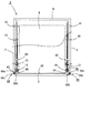
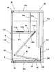
- the fall prevention device 1 includes a bottom plate 2 formed in a square shape, and a left side plate 3 that stands up from the left end of the bottom plate 2.
- 4 is provided with a back plate 5 connected to the back side end of 4 and a top plate 6 facing the bottom plate 2.
- the left side plate 3, the right side plate 4, the back plate 5 and the top plate 6 are all made of a metal plate formed into a square shape.
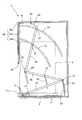
- the 1st left spindle holding member 11 is fixed to the front side middle part of the left side of the said baseplate 2 as shown in FIG.1 or FIG.2, and this baseplate is shown in FIG.1 or FIG.3.
- a first right support shaft holding member 12 is fixed to the front right halfway portion 2.
- the first left support shaft holding member 11 and the first right support shaft holding member 12 are respectively formed on base portions 11a and 12a fixed to the upper surface of the bottom plate 2 and on the upper portions of the base portions 11a and 12a.
- support shaft holding portions 11b, 12b having shaft insertion holes (reference numerals omitted) formed in the left-right direction, and the support shaft holding portion 11b of the left support shaft holding member 11 is The left support shaft 13 is inserted.
- the right support shaft 14 is inserted into the support shaft holding portion 12 b of the first right support shaft holding member 12.
- a left rotating rod 15 is attached to the left support shaft 13.
- the left rotation rod 15 has a length from the front side to the back side of the overturn prevention device 1, and the first support shaft 13 is inserted in the middle of the front side.
- Left insertion hole 15a is formed, and a second left insertion hole 15b is formed further on the front side (front end side) than the position where the first left insertion hole 15a is formed.
- a right turning rod 16 is attached to the right support shaft 14.
- the right turning rod 16 is formed in the same shape as the left turning rod 15 and the first right insertion hole 16a through which the right support shaft 14 is inserted is inserted in the middle part on the front side.
- a second right insertion hole 16b is formed further on the front side (front end side) than the position where the first right insertion hole 16a is formed.
- the left pivot rod 15 is pivotally supported with the left pivot shaft 13 (fulcrum) as a pivot center, and the right pivot rod 16 pivots the right pivot shaft 14 (fulcrum).
- the front side end (power point) of the left turning rod 15 the rear side end (rear end) of the left turning rod 15 is supported.
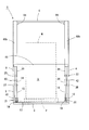
- a load supporting member 17 for supporting the load of the placed object is disposed on the bottom plate 2.
- the load support member 17 is formed to have a length and width slightly narrower than the length and width of the bottom plate 2.
- the front side end (front end) is As shown in FIG. 2 or FIG. 3, the bottom plate 2 projects slightly forward from the front side end (front end). Further, the rear side end (rear end) of the load support member 17 is supported and abutted on the bottom plate 2.
- a second left support shaft holding member 18 is attached to the left end of the load support member 17 on the front side, and a second right support holding member 19 is attached to the right side of the front side. Is fixed.
- the second left support shaft holding member 18 and the second right support shaft holding member 19 are formed on base portions 18a and 19a whose bottom surfaces are fixed to the bottom plate 2, and on the upper portions of the base portions 18a and 19a. And support shaft holding portions 18b and 19b with shaft insertion holes (reference numerals omitted) formed in the left-right direction.
- the left rotation shaft 21 is inserted.
- the right rotation shaft 22 is inserted into the support shaft holding portion 19 b of the second right support shaft holding member 19.
- the left rotation shaft 21 is inserted into a second left insertion hole 15b formed in the left rotation rod 15, and the right rotation shaft 22 is As shown in FIG. 2, the second right insertion hole 16b formed in the right turning rod 16 is inserted. That is, the left side of the front side of the load support member 17 is rotatably supported and connected via the left rotation shaft 21, and the right side of the front side of the load support member 17 is the right rotation shaft. Via 22, it is supported and connected to be rotatable. Therefore, as will be described later, when an object is placed on the load support member 17, the load support member 17 moves downward while rotating around the left rotation shaft 21 and the right rotation shaft 22. Eventually, the lower surface abuts on the upper surface of the bottom plate 2.
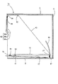
- one end of the first left link member 28 is connected to the first end of the first left link member 28 via the first left link side convex portion 27 as shown in FIG.
- the left link side convex portion 27 is connected to be rotatable.
- one end of the second left link member 30 is connected to the second left link side convex portion 29 via the second left link side convex portion 29 at the other end of the first left link member 28. It is pivotally connected to the center.
- a third left link-side convex portion 31 is formed in the middle portion of the second left link member 30 at the other end side, and a fourth left link member 30 is formed at the other end of the second left link member 30.
- a link-side convex portion 32 is formed.
- a fifth left link side convex portion 33 is further formed in the middle portion of the first left link member 28.
- the first to fifth left link side convex portions 27, 29, 31, 32, 33 all have a length in the thickness direction of the left side plate 3.
- one end of the first right link member 36 is connected to the first end of the first right link member 36 via the first right link side convex portion 35, as shown in FIG.
- the right link side convex portion 35 is connected to be rotatable.
- one end of the second right link member 38 is connected to the second right link side convex portion 37 via the second right link side convex portion 37 at the other end of the first right link member 36. It is pivotally connected to the center.
- the second right link member 38 has a third right link side convex portion 40 formed in the middle of the other end side, and the other end of the second right link member 38 has a fourth right side.
- a link-side convex portion 41 is formed.
- a fifth right link side convex portion 42 is further formed in the middle portion of the first right link member 36.
- the first to fifth right link side convex portions 35, 37, 40, 41, 42 all have a length in the thickness direction of the right side plate 4.
- the left linear body 43 is connected to the other end of the second left link member 30, and the other end of the second right link member 38 is connected to FIG.
- one end of the right linear body 44 is connected.
- the left linear body 43 and the right linear body 44 are each composed of a flexible linear body such as a chain or a wire, and the other ends of the left linear body 43 and the right linear body 44.
- the overturn prevention member 45 is fixed to the left end side and the right end side of the overturn prevention member 45 that moves up and down on the front side of the left side plate 3 and the right side plate 4.
- the fall prevention member 45 is a rod-like body having a length in the horizontal direction.
- the lower end of the left elastic member 47 is fixed to the rear end side of the left side of the bottom plate 2, and the upper end of the left elastic member 47 is connected to the rear end of the left rotating rod 15. It is locked.
- the lower end of the right elastic member 48 is fixed to the rear end side of the right side of the bottom plate 2, and the upper end of the right elastic member 48 is connected to the rear end of the right rotating rod 16. It is locked.
- the left elastic member 47 and the right elastic member 48 are constituted by (pulling) coil springs in the overturn prevention device 1 according to the present embodiment. The rear end side of 16 is urged downward (in the direction of the bottom plate 2).
- first to fifth left link side convex portions 27, 29, 31, 32, 33 are inserted into the left side plate 3, and the first left link member 28 and the second left link member 30 are inserted.
- the first to fifth left guide grooves 51... 55 corresponding to the trajectory of the moving operation are formed in an arc shape.
- first to fifth right link side convex portions 35, 37, 40, 41, 42 are inserted into the right side plate 4, and the first right link member 36 and the second right link member 38 are inserted.
- the first to fifth right guide grooves 56... 60 corresponding to the trajectory of the moving operation are formed in an arc shape.
- the first left linear body guide member 63 and the first right linear body guide member 65 are disposed slightly rearward from the front surfaces (front ends) of the left side plate 3 and the right side plate 4, respectively.
- the left linear body guide member 64 and the second right linear body guide member 66 are disposed in the vicinity of the front surface of the left side plate 3 and the right side plate 4, respectively.
- a left lifting guide member 68 whose planar shape is formed in a U shape is fixed to the front surface of the left side plate 3, and a flat surface is provided to the front side of the right side plate 4.
- a right elevating guide member 69 having a U shape is fixed.
- the left elevating guide member 68 and the right elevating guide member 69 are respectively fixed plate portions 68a and 69a fixed to the front surface of the left side plate 3 or the right side plate 4, and the rear surface faces the front surface of the fixed plate portions 68a and 69a.
- the front plate portions 68c and 69c that are opposed to each other and the outer plate portions 68c and 69c that are flush with the outer surface of the left side plate 3 or the right side plate 4 are arranged on the right side of the left lifting guide member 68. Is opened, and the left side of the right elevating guide member 69 is open. The left end side of the tipping prevention member 45 described above is inserted into the left lifting guide member 68, and the right end side of the tipping prevention member 45 is inserted into the right lifting guide member 69. Note that the lower ends of the left elevating guide member 68 and the right elevating guide member 69 are positioned in the vicinity of the intermediate position of the left side plate 3 or the right side plate 5, respectively.
- the front plate portions 68b and 69b are position holding means that constitute the present invention.
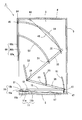
- the fall-preventing device 1 has the above-described fall-preventing member 45 at the uppermost position as shown in FIG. 2, FIG. 3 or FIG. Further, the front end (front side end portion) of the load support member 17 is spaced above the upper surface of the bottom plate 2, and the rear end (back side end portion) thereof is the bottom plate 2. It is in contact with the upper surface of the surface and slightly inclined as a whole. Further, the left turning rod 15 and the right turning rod 16 also have their front ends (front end portions) spaced above the upper surface of the bottom plate 2 and are slightly inclined as a whole.
- the state of the fall prevention member 45, the load support member 17, the left turning rod 15, the right turning rod 16 and the like shown in FIG. 2 or FIG. the pallet P on which the above-mentioned figurine W is placed is supported by left and right forks (not shown) and driven by the forklift, the left plate 2 and the right plate 3 are moved.
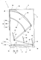
- the pallet P is moved down into the toppling prevention device 1 and then gradually lowered, the load of the pallet P and the object W is gradually supported by the load support member 17 and the load support member. 17 moves downward, and eventually the lower surface thereof comes into contact with the upper surface of the bottom plate 2.
- the left pivot rod 15 is guided by the first left guide groove 51 while the left pivot shaft 13 is the pivot center, and the right pivot rod 2 and 3 in FIG. 2 or FIG. 3 against the elastic force of the left elastic member 47 or the right elastic member 48 with the right support shaft 14 as the center of rotation while being guided by the first right guide groove 56.
- the first left link member 28 is pulled by the weight of the fall prevention member 45 while the second and second link members 28 are pulled.
- the first right link member 36 moves while being guided by the fifth left guide grooves 52 and 55, and the second and fifth right guides 36 are pulled while being pulled by the weight of the fall prevention member 45. It moves while being guided by the grooves 57 and 60, respectively.
- the second left link member 30 and the second right link member 38 are moved together with the first movement.
- the fall prevention member 45 moves from the standby position to the left lifting guide.
- the lower end position of the left elevating guide member 68 and the right elevating guide member 69 (the front of the object to be placed) is lowered while being guided by the member 68 and the right elevating guide member 69. And a position where the insertion space S into which the fork can be inserted is left (see FIG. 7).
- the fork is inserted from the insertion space S formed below the fall-preventing member 45. Is inserted into the pallet P and the forklift is driven to raise (lift) the pallet P. As the pallet P is raised, the load support member 17, the left rotating rod 15 and the right rotating rod 16 are returned to the standby state by the elastic force of the left elastic member 47 and the right elastic member 48, respectively.
- the first and second left link members 28 and 30 and the first and second right link members 38 and 38 also operate in the direction opposite to the above-described rotation operation. By the operation, the fall prevention member 45 also returns to the standby state. Therefore, by driving the forklift, the pallet P on which the above-mentioned figurine W is placed can be taken out from the fall prevention device 1 to the outside.
- the fall prevention device 1 does not use any configuration that is electrically driven as a configuration of the device that prevents the placed object from falling and falling due to vibration such as an earthquake. Therefore, even if a power outage occurs due to the occurrence of the earthquake or the like, it can function without fail. Further, in the fall prevention device 1, the first turning rod 15 that turns in the same manner as a lever and the left linear body 43 connected to the left end side of the fall prevention member 45 are between the first linear body 43. And the second left link members 28 and 30 are interposed between the right linear rod 44 and the right linear body 44 connected to the right end side of the fall prevention member 45.
- the left rotation rod 15 and the right rotation rod 16 are located on the front side of the left rotation rod 15 and the right rotation rod 16 (front end side middle portion). ), The left support shaft 13 or the right support shaft 14 pivoted at the center of rotation, and the load support member 17 or the left rotation rod 15 or the right rotation rod 16 from the position of the front end of the force support point. It is an action point from the left support shaft 13 or the right support shaft 14 that is the fulcrum than the distance to the left support shaft 13 or the right support shaft 14. Since the distance to the rear end position of the left rotation rod 15 and the right rotation rod 16 is much longer, the fall prevention member 45 is moved up and down over a distance considerably longer than the distance by which the load support member 17 descends. Can be made.
- the first and second left link members 28 and 30 and the first and second right link members 36 and 38 are constituent elements.
- the rear end side of the left rotating rod 15 and the left linear body 43 may be directly connected, and the right rotating rod 16 and the right linear body 44 may be directly connected (not shown).
- the up / down range of the fall prevention member 45 is shorter than that of the fall prevention device 1 according to the embodiment described above, but the load of the mounted object W is reduced. By being supported by the load support member 17, the fall prevention member 45 can be moved up and down over a distance longer than the distance by which the load support member 17 descends.
- a fall prevention member constituting the present invention a rod-shaped body (fall over prevention member 45) having a length in the horizontal direction is illustrated and described.
- the fall-preventing member constituting the above invention may be not only a rod-like body but also a plate-like body.
- a rod-like body having a length in the horizontal direction such as an insulator is connected to be freely rotatable up and down. And is configured to be guided by the second left linear body guide member 64 and the second right linear body guide member 66 while being bent by being raised and partially bent on the upper end side. Also good.
- the plate body (load support member 17) formed in a square shape is illustrated and described as the load support member constituting the present invention.
- the load supporting member constituting the invention may be, for example, a rod-shaped body, a wire or belt stretched in the horizontal direction, etc., as long as it supports at least all or a part of the load of the mounted object. good.
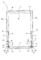
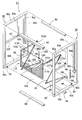
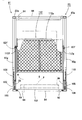
- the fall prevention device 81 has a left frame 82 and a right frame 83 which are each formed into a frame shape by a hollow steel frame and are formed in the same shape, and the left frame 82 and the right frame.
- Four horizontal rods 84 connecting the frame 83 are provided.
- the left frame 82 includes an upper left rod 82a and a lower left rod 82b that are formed to be the same length and parallel to each other, and a left front rod 82c and a left rear rod 82d that are formed to be the same length and are parallel to each other.
- the right frame 83 includes an upper right collar 83a and a lower right collar 83b, a right front collar 83c, and a right rear collar 83d.
- the first left vertical rod 82e hangs down slightly from the center of the lower surface of the upper left rod 82a constituting the left frame 82, and from slightly above the center of the rear surface of the left front rod 82c.
- a left parallel rod (a left stopper constituting the present invention) 82f which is parallel to the upper left rod 82a and fixed at the lower end of the first left vertical rod 82e, is fixed, and the first left vertical rod 82e
- a left fixed rotation shaft 87 is erected in the horizontal direction at a position fixed to the left parallel rod 82f.
- a second left vertical rod 82g that is parallel to the left rear rod 82d is suspended from the lower surface of the middle portion of the rear left side of the upper left rod 82a, and the lower end of the second left vertical rod 82g
- a left connection rod 82h is connected to the front of the left rear rod 82d.
- the other left rotation shaft 89 projects from the right frame 83 side on the front end side of the inner surface of the lower left rod 82b constituting the left frame 82.
- a shaft support column 90 is erected in the middle of the rear end side of the upper surface of the lower left rod 82b.
- the left support shaft 91 constituting the present invention protrudes toward the right frame 83 on the shaft support column 90. It is installed.
- the first left vertical rod 82e, the left parallel rod 82f, the left fixed rotation shaft 87, the second left vertical rod 82g, the left connection rod 82h, and the other left rotation shaft 89 are also provided on the right frame 83.
- the first right vertical rod 83e, the right parallel rod 83f, the right fixed pivot shaft 88, the second right vertical rod 83g, and the right connection rod 83h formed in the same shape as the shaft support column 90 and the left support shaft 91.
- the other right rotation shaft 92 (see FIG. 11), a shaft support column 94, and a right support shaft 93 are provided.
- the right parallel rod 83f is a right stopper constituting the present invention.
- the left support shaft 91 is rotatably attached with a left turning rod 95 constituting the present invention.
- the right support shaft 93 is rotatably attached with a right turning rod 96 constituting the present invention.
- An insertion shaft (reference numeral is omitted) through which the left support shaft 91 is inserted is formed in the middle part on the rear end side of the left rotating rod 95, and a connecting shaft (reference numeral is omitted) is formed at the front end.
- one end of the left link member 98 is rotatably connected.
- an insertion shaft (reference numeral is omitted) through which the right support shaft 93 is inserted is formed in the middle part of the right rotation rod 96 on the rear end side, and a connecting shaft (reference numeral is omitted) at the front end.
- One end of the right link member 99 is rotatably connected through the. Long holes 98a and 99a are formed on the other end sides of the left link member 98 and the right link member 99, respectively.
- the load supporting member 101 constituting the present invention is disposed between the lower left rod 82b constituting the left frame 82 and the lower right rod 83b constituting the right frame 83.
- the load support member 101 is a plate formed in a rectangular shape, and supports the entire load of the object to be loaded as described later.
- the front of the left end (on the lower surface) of the load support member 101 is The other left rotation shaft 89 is rotatably supported, and the front of the right end is rotatably supported by the other right rotation shaft 92 (see FIG. 11).
- a left shaft support piece 102 is erected on the left side of the rear end of the load support member 101, and the left shaft is fixed to the left shaft 103 through one left rotation shaft 103 fixed to the upper end side of the left shaft support piece 102.
- the rear end of the rotary rod 95 is rotatably connected.
- a right shaft support piece 105 is provided upright on the left side of the rear end of the load support member 101, and the right shaft is supported via one right rotation shaft 106 fixed to the upper end side of the right shaft support piece 105.
- the rear end of the rotary rod 96 is rotatably connected.
- the fall prevention device 112 includes a fall prevention member 112 as a constituent element. As will be described later, the fall prevention member 112 includes a rectangular fall prevention member main body 112a (refer to FIG. 9 or FIG.
- the left arm 112b has a base end fixed to the left end of the back surface of the fall prevention member main body 112a, and a right arm 112c having a base end fixed to the right end of the back surface of the fall prevention member main body 112a.
- sliding shafts 112d and 112e inserted into elongated holes 98a and 99a formed on the other end side of the left link member 98 or the right link member 99 are provided at the distal ends of the left arm 112b and the right arm 112c. Is fixed.
- the fall prevention member main body 112a when the fall prevention member main body 112a is moved to the front of the object W placed on the load support member 101, The left contact member 112f and the right contact member 112g that contact the upper surface of the left parallel rod 92f or the right parallel rod 83f, which are the left stopper or the right stopper constituting the present invention, are fixed. Further, an insertion hole (not shown) through which the left fixed rotation shaft 87 is inserted is formed in the middle portion on the front end side of the left arm 112b, and the right fixed portion is formed in a middle portion on the front end side of the right arm 112c. An insertion hole (not shown) through which the rotation shaft 88 is inserted is formed. Therefore, as will be described later, the fall prevention member 112 is rotated around the left fixed rotation shaft 87 and the right fixed rotation shaft 88.
- the rear end side of the load support member 101 is slightly higher than the front end side, as shown in FIG. 10 or FIG.
- the fall prevention member main body 112a that constitutes the fall prevention member 112 is in a substantially horizontal state at the top.
- the sliding shaft 112d fixed to the left arm 112b is positioned at the lowermost part (one end side) of the long hole 98a formed in the left link member 98, and is fixed to the right arm 112c in the same manner.
- the sliding shaft 112e thus positioned is located at the lowermost (one end side) of the long hole 99a formed in the right link member 99 (see FIG. 10).
- the pallet P on which the above-described object W is placed is supported by left and right forks (not shown) and is moved into the object-containing space formed in the fall prevention device 1 by driving the forklift.
- the load support member 101 includes the left elastic member 99 and the right elastic member.
- the rear end side descends (rotates) about the other left rotation shaft 89 and the other right rotation shaft 92 against the elastic force of the member 110.
- the left rotating rod 95 has the left supporting shaft 91 as a rotation center
- the right rotating rod 96 has the right rotating shaft. It rotates in the clockwise direction in FIG.
- the left turning rod 95 is turned
- the left link member 98 is lifted while having one end side as a turning center, and pushes up the left arm 112b constituting the fall prevention member 112.
- the right pivot rod 96 is pivoted, the right link member 99 rises with one end thereof as the pivot center and pushes up the right arm 112c constituting the fall prevention member 112.
- the entire fall prevention member 112 pushed up by the left link member 98 and the right link member 99 is centered on the left fixed rotation shaft 87 and the right fixed rotation shaft 88 in FIG. It rotates in the counterclockwise direction and eventually stops at the position shown in FIG.
- This state is a fall prevention state after the placing object W (and the pallet P) is placed on the load support member 101.
- the left contact member 112f is The right abutting member 112g abuts on the right-side transition bar 83f.
- the sliding shaft 112d fixed to the left arm 112b is located on the most other end side of the long hole 98a formed in the left link member 98, and is fixed to the right arm 112c in the same manner.
- the sliding shaft 112e is located on the most other end side of the long hole 99a formed in the right link member 99 (see FIG. 12). Therefore, even if a force is applied downward to the fall prevention member 112, the fall prevention member 112 will not be lowered any more, and the fall prevention member 112 will have the left fixed rotation shaft 87 and the right fixed rotation shaft 88. Therefore, even if the above-described figurine W comes into contact with the toppling prevention member main body 112a due to vibration such as an earthquake, there is no risk of further toppling.
- a fork of a forklift (not shown) that lifts the object W from above the load support member 101 is inserted from the front side below the fall prevention member main body 112. An insertion space S is formed (see FIG. 13).
- the configuration of the apparatus that prevents the mounted object from falling and falling due to vibration such as an earthquake is electrically Since it does not use any driving structure, it can function without fail even if a power failure occurs due to the occurrence of the earthquake or the like.
Landscapes
- Engineering & Computer Science (AREA)
- Mechanical Engineering (AREA)
- Warehouses Or Storage Devices (AREA)
- Handcart (AREA)
- Casings For Electric Apparatus (AREA)
- Vibration Prevention Devices (AREA)
Abstract
Provided is a novel article overturn prevention device that is capable of preventing an article placed on a placement board from falling due to vibrations from earthquakes, etc., without using any electrically operated member as a component. The present invention is provided with an overturn prevention member 45: which has a left end connected to a left-rotation rod 15 rotatably supported on a left spindle 13 arranged partway along the front-end side; which has a right end connected to a right-rotation rod 16 rotatably supported on a right spindle 14 arranged partway along the front-end side or the rear-end side; which descends or rotates due to the rotation of the left-rotation rod 15 and the right-rotation rod 16 when the load from the article W is supported by a load support member 17 for supporting all or a part of the load of the article W; and which is positioned on the front side of the article W when the overturn prevention member 45 has descended to the lowest position. When the overturn prevention member 45 has descended to the lowest position, an insertion space into which an article lifting means is inserted from the front-surface side is formed therebelow.
Description
本発明は、棚、ラック、キャビネット等の載置板上に載置された製品や部品等の載置物が地震などの振動により該載置板から転倒したり脱落したりすることを防止するために使用される載置物の転倒防止装置に関するものである。
The present invention is to prevent a product or part mounted on a mounting plate such as a shelf, rack or cabinet from falling or dropping from the mounting plate due to vibration such as an earthquake. It is related with the fall prevention apparatus of the mounted material used for.
これまで地震などの発生により棚やラック等の載置板上に載置された製品等が転倒することを防止するための装置としては、例えば、特開2010-273955号公報(特許文献1)に開示されたもの(収納物落下防止ユニット)が提案されている。この公報に開示された収納物落下防止ユニットは、地震による振動を検出する地震計からの信号を受けて作動するアクチュエータの駆動により、待機状態から落下防止アームが下降するものである。
As an apparatus for preventing a product or the like placed on a placing plate such as a shelf or a rack from tipping over due to the occurrence of an earthquake or the like, for example, JP 2010-273955 A (Patent Document 1) (The stored item fall prevention unit) has been proposed. The stored item fall prevention unit disclosed in this publication is such that the fall prevention arm descends from a standby state by driving an actuator that operates in response to a signal from a seismometer that detects vibration due to an earthquake.
したがって、上記特許文献1に開示された収納物落下防止ユニットによれば、上記収納物は、地震の発生により下降した落下防止アームに当接することにより、落下することがない。
Therefore, according to the stored item fall prevention unit disclosed in Patent Document 1, the stored item does not fall by coming into contact with the fall preventing arm that has been lowered due to the occurrence of an earthquake.
しかしながら、上記特許文献1に開示されたものでは、地震計とアクチュエータを構成要素とし、これらは電気的に動作するものであることから、必ず電源を必要とするばかりではなく、地震により停電した場合には作動しない。
However, in the one disclosed in the above-mentioned Patent Document 1, the seismometer and the actuator are constituent elements, and these operate electrically, so that not only a power source is necessarily required but also a power failure due to an earthquake. Does not work.
そこで、本発明は、上述した従来の技術が有する課題を解決するために提案されたものであって、電気的に作動する部材を一切構成要素とすることがなく、地震等の振動により載置された載置物が落下することを防止することができる新規な載置物の転倒防止装置を提供することを目的とするものである。
Therefore, the present invention has been proposed to solve the above-described problems of the prior art, and does not include any electrically operated member at all, and is placed by vibration such as an earthquake. It is an object of the present invention to provide a novel device for preventing a fall of a placed object that can prevent the placed object from falling.
本発明は、上記課題を解決するために提案されたものであって、第1の発明(請求項1記載の発明)は、正面側は解放されてなるとともに内側には載置物が収容される載置物収容空間が形成されてなる載置物の転倒防止装置であって、水平方向に長さを有する左支軸を回動中心として回動自在に配置された左回動杆と、水平方向に長さを有する右支軸を回動中心として回動自在に配置された右回動杆と、左端は上記左回動杆の前端側又は後端側に連結され右端は上記右回動杆の前端側又は後端側に連結され上記載置物の荷重の全部又は一部を支持する荷重支持部材と、上記荷重支持部材の前端側又は後端側が、又は、上記左回動杆若しくは右回動杆の前端側又は後端側が、常に上方に位置するように付勢してなる弾性部材と、上記荷重支持部材上に載置物が載置される前の待機状態においては、該荷重支持部材の上方又は斜め上方である待機位置に待機し、該荷重支持部材上に載置物が載置された後の転倒防止状態においては、上記待機位置から載置物の正面側に移動する転倒防止部材と、を備え、上記左支軸は上記左回動杆の前端側又は後端側の何れか一方において該左回動杆を軸支し、上記右支軸は上記右回動杆の前端側又は後端側の何れか一方において該右回動杆を軸支し、上記転倒防止部材の左端と上記左回動杆とは、線状体からなる線状連結材、又は単一又は複数のリンク部材からなるリンク連結材、若しくは上記線状体と複数のリンク部材とからなる複合的連結材により互いに連結され、また、上記転倒防止部材の右端と上記右回動杆とは、線状体からなる線状連結材、又は単一又は複数のリンク部材からなるリンク連結材、若しくは上記線状体と複数のリンク部材とからなる複合的連結材により互いに連結されてなるとともに、上記転倒防止部材が上記転倒防止状態とされた際には、上記荷重支持部材上から載置物を持ち上げるフォークリフトのフォークその他の機械又は装置を構成する載置物持ち上げ手段が正面側から挿入される挿入空間が該転倒防止部材の下方に形成されてなることを特徴とするものである。
The present invention has been proposed in order to solve the above-mentioned problems. In the first invention (the invention described in claim 1), the front side is released and the placed object is accommodated inside. A device for preventing a fall of a placement object in which a placement object accommodation space is formed, and a left turning rod that is arranged to be rotatable about a left support shaft having a length in the horizontal direction, and a horizontal direction. A right rotating rod that is arranged to be rotatable about a right support shaft having a length, and a left end is connected to a front end side or a rear end side of the left rotating rod, and a right end is the right rotating rod. A load support member connected to the front end side or the rear end side and supporting all or part of the load of the figurine described above, and the front end side or the rear end side of the load support member, or the left rotation rod or the right rotation An elastic member that is urged so that the front end side or the rear end side of the bag is always positioned upward, and the load support In the standby state before the placement object is placed on the material, it stands by at a standby position that is above or obliquely above the load support member, and falls after the placement object is placed on the load support member And a fall prevention member that moves from the standby position to the front side of the placement object, and the left support shaft is rotated counterclockwise at either the front end side or the rear end side of the left rotation rod. The right support shaft supports the right rotation shaft on either the front end side or the rear end side of the right rotation shaft, and the left end of the fall prevention member and the left rotation The scissors are connected to each other by a linear connecting material made of a linear body, a link connecting material made of a single or a plurality of link members, or a composite connecting material made of the linear body and a plurality of link members, The right end of the fall prevention member and the right turning rod are linearly connected with a linear body. Or connected to each other by a link connecting material consisting of a single or a plurality of link members, or a composite connecting material consisting of the linear body and a plurality of link members, and the fall prevention member is in the fall prevention state. When this is done, an insertion space is formed below the anti-falling member into which the object lifting means constituting the fork of the forklift or other machine or apparatus for lifting the object from above the load support member is inserted from the front side. It is characterized by.
この第1の発明に係る載置物の転倒防止装置は、正面側は解放されてなるとともに内側には載置物が収容される載置物収容空間が形成されている。この収容空間を形成する部材は、左側板や右側板を備えてなるもの(請求項2記載の発明参照)であっても良いし、左フレームや右フレームを備えてなるもの(請求項8記載の発明参照)であっても良い。また、この第1の発明では、左回動杆と右回動杆とを備えている。上記左回動杆及び右回動杆は、水平方向に長さを有する左支軸又は右支軸を回動中心として回動自在とされているものである。そして、上記左支軸は上記左回動杆の前端側又は後端側の何れか一方において該左回動杆を軸支し、上記右支軸は上記右回動杆の前端側又は後端側の何れか一方において該右回動杆を軸支している。
The device for preventing overturning of the mounted object according to the first aspect of the present invention is formed with a mounted object storage space in which the mounted object is stored inside while the front side is released. The member forming the accommodation space may be a left side plate or a right side plate (refer to the invention described in claim 2), or a left frame or a right frame (claim 8). (See invention of the present invention). Moreover, in this 1st invention, the left rotation rod and the right rotation rod are provided. The left rotation rod and the right rotation rod are rotatable about a left or right support shaft having a length in the horizontal direction. The left support shaft supports the left rotation shaft at either the front end side or the rear end side of the left rotation shaft, and the right support shaft supports the front end side or the rear end of the right rotation shaft. The right turning rod is pivotally supported on either one of the sides.
また、この発明では、荷重支持部材が構成要素とされ、この荷重支持部材は、左端が上記左回動杆に連結され右端は上記右回動杆に連結されてなるものであり、上記載置物の荷重の全部又は一部を支持するものである。したがって、上記左支軸が上記左回動杆の前端側において該左回動杆を軸支し、上記右支軸が上記右回動杆の前端側において該右回動杆を軸支し、且つ、上記荷重支持部材の左端が上記左回動杆の前端側に連結され、該荷重支持部材の右端が上記右回動杆の前端側に連結されている場合において、該荷重支持部材に載置物の荷重が支持されると、梃子の原理により、上記左回動杆と右回動杆のそれぞれ後端は、該左回動杆と右回動杆のそれぞれ前端が下降する長さよりも大きく上昇する。逆に、上記左支軸が上記左回動杆の後端側において該左回動杆を軸支し、上記右支軸が上記右回動杆の後端側において該右回動杆を軸支し、且つ、上記荷重支持部材の左端が上記左回動杆の後端側に連結され、該荷重支持部材の右端が上記右回動杆の後端側に連結されている場合において、該荷重支持部材に載置物の荷重が支持されると、梃子の原理により、上記左回動杆と右回動杆のそれぞれ前端は、該左回動杆と右回動杆のそれぞれ前端が下降する長さよりも大きく上昇する。なお、この荷重支持部材は、載置物の荷重の少なくとも一部が支持されるものであれば良く、その形状や面積は特に限定されるものではない。例えば、載置物の荷重の多くは、上記底板により支持され、一部の荷重はこの荷重支持部材に支持されるように、水平に配置されたバーであっても良いし、載置物全体が載置される板体から構成されてなるものであっても良い。
Further, in the present invention, the load support member is a component, and the load support member has a left end connected to the left rotation rod and a right end connected to the right rotation rod. It supports all or part of the load. Therefore, the left support shaft pivotally supports the left rotation rod on the front end side of the left rotation rod, the right support shaft pivotally supports the right rotation rod on the front end side of the right rotation rod, In addition, when the left end of the load support member is connected to the front end side of the left rotation rod and the right end of the load support member is connected to the front end side of the right rotation rod, the load support member is mounted on the load support member. When the load of the figurine is supported, according to the principle of the lever, the rear ends of the left rotating rod and the right rotating rod are larger than the lengths at which the front ends of the left rotating rod and the right rotating rod are lowered. To rise. Conversely, the left support shaft pivotally supports the left rotation rod at the rear end side of the left rotation rod, and the right support shaft pivots the right rotation rod at the rear end side of the right rotation rod. And when the left end of the load support member is connected to the rear end side of the left rotating rod and the right end of the load support member is connected to the rear end side of the right rotating rod, When the load of the mounted object is supported by the load support member, the front ends of the left and right rotating rods are lowered according to the principle of the lever. Rise more than the length. In addition, this load support member should just support at least one part of the load of a mounting object, and the shape and area are not specifically limited. For example, most of the load of the mounted object is supported by the bottom plate, and a part of the load may be a bar arranged horizontally so as to be supported by the load supporting member, or the entire mounted object may be mounted. It may be configured by a plate body to be placed.
また、この発明では、弾性部材が構成要素とされている。この弾性部材は、上記荷重支持部材の前端側又は後端側が常に上方に位置するように付勢してなるものであっても良いし、上記左回動杆若しくは右回動杆の前端側又は後端側が、常に上方に位置するように付勢してなるものであっても良い。なお、上記弾性部材は、左回動杆若しくは右回動杆の前端側又は後端側が、常に上方に位置するように付勢するものにおいては、該左回動杆を付勢する弾性部材と、上記右回動杆を付勢する弾性部材とを別個に配置しても良い。また、この(これらの)弾性部材は、上記荷重支持部材若しくは左回動杆又は右回動杆の前端側又は後端側が常に上方に位置するように付勢するものであることから、該弾性部材は、上記荷重支持部材若しくは左回動杆又は右回動杆の下方に配置されているものばかりではなく、これらの上方に配置されているものであっても良い。また、この弾性部材の形状は、弦巻バネであっても板バネであっても良い。
In the present invention, the elastic member is a constituent element. This elastic member may be urged so that the front end side or the rear end side of the load supporting member is always positioned upward, or the front end side of the left rotating rod or the right rotating rod or The rear end side may be urged so as to be always positioned upward. The elastic member is an elastic member that urges the left rotating rod when the front rotating end or the rear rotating end of the right rotating rod is always positioned upward. The elastic member that urges the right rotating rod may be disposed separately. Further, since these (these) elastic members urge the front end side or the rear end side of the load support member or the left rotation rod or the right rotation rod to be always positioned upward, The members are not limited to those disposed below the load support member, the left pivot rod, or the right pivot rod, but may be disposed above them. The shape of the elastic member may be a string spring or a leaf spring.
また、この発明では、転倒防止部材を構成要素としている。この転倒防止部材は、上記荷重支持部材上に載置物が載置される前の待機状態においては、該荷重支持部材の上方又は斜め上方である待機位置に待機し、該荷重支持部材上に載置物が載置された後の転倒防止状態においては、上記待機位置から載置物の正面側に移動するものである。そして、この転倒防止部材の左端と上記左回動杆とは、線状体からなる線状連結材、又は単一又は複数のリンク部材からなるリンク連結材、若しくは上記線状体と複数のリンク部材とからなる複合的連結材により互いに連結され、また、該転倒防止部材の右端と上記右回動杆とは、線状体からなる線状連結材、又は単一又は複数のリンク部材からなるリンク連結材、若しくは上記線状体と複数のリンク部材とからなる複合的連結材により互いに連結されている。したがって、この発明では、上記荷重支持部材上に載置物が載置されると、上記線状連結材、上記リンク連結部材又は上記複合的連結部材を介して、上記転倒防止部材は、上記待機状態から上記転倒防止状態に移動する。そしてさらに、この発明では、上記転倒防止部材が上記転倒防止状態とされた際には、上記荷重支持部材上から載置物を持ち上げるフォークリフトのフォークその他の機械又は装置を構成する載置物持ち上げ手段が正面側から挿入される挿入空間が該転倒防止部材の下方に形成されている。
Further, in the present invention, the fall prevention member is a constituent element. In the standby state before the placing object is placed on the load support member, the fall prevention member stands by at a standby position that is above or obliquely above the load support member, and is placed on the load support member. In the fall prevention state after the object is placed, the object moves from the standby position to the front side of the object. And the left end of this fall prevention member and the above-mentioned left rotation rod are a linear connecting material consisting of a linear body, a link connecting material consisting of a single or a plurality of link members, or the above linear body and a plurality of links The right end of the fall-preventing member and the right pivot rod are composed of a linear coupling material composed of a linear body, or a single or a plurality of link members. It is mutually connected by the link connection material or the composite connection material which consists of the said linear body and a some link member. Therefore, according to the present invention, when an object is placed on the load support member, the fall prevention member is in the standby state via the linear connecting member, the link connecting member, or the composite connecting member. To the fall prevention state. Still further, in the present invention, when the overturn prevention member is in the overturn prevention state, the forelift lifting means constituting the fork or other machine or device of the forklift for lifting the placement from the load support member is in front. An insertion space to be inserted from the side is formed below the fall prevention member.
したがって、上述した構成に係る載置物の転倒防止装置によれば、上記載置物持ち上げ手段により載置物の荷重の全部又は一部が上記荷重支持部材により支持されると、上記弾性部材の弾性力に抗して、該載置物の荷重により上記左回動杆は上記左支軸を中心に、上記右回動杆は上記右支軸を中心にそれぞれ回動し、この結果、該左回動杆と右回動杆の後端側又は前端側は、上記荷重支持部材が下降する距離よりも長い距離に亘って上昇し、こうした左回動杆と右回動杆の回動と、上記線状連結材、上記リンク連結部材又は上記複合的連結部材の動作を介して、上記待機状態にあった転倒防止部材は、上記転倒防止状態となる。そして、このように転倒防止状態となった転倒防止部材の下方には、上記挿入空間が形成されていることから、上記載置物を残置した状態で上記載置物持ち上げ手段を外側に移動することができる。この状態において、地震等の振動により上記載置物が転倒する方向に傾くと、該載置物は上記転倒防止部材に当接し、転倒することが防止される。一方、上記載置物を上記荷重支持板上から取り除く場合には、上記載置物持ち上げ手段を外側から上記挿入空間内に挿入し、荷重支持部材上から持ち上げると、上記弾性部材の弾性力により、上記荷重支持部材、左回動杆、右回動杆並びに転倒防止部材は、それぞれ元の状態(待機状態)に復帰する。
Therefore, according to the fall prevention device for a placement object according to the above-described configuration, when all or a part of the load of the placement object is supported by the load support member by the above-described object lifting means, the elastic force of the elastic member is reduced. On the contrary, due to the load of the mounting object, the left rotating rod rotates about the left supporting shaft, and the right rotating shaft rotates about the right supporting shaft. And the rear end side or the front end side of the right rotating rod rises over a distance longer than the distance by which the load supporting member descends, and the rotation of the left rotating rod and the right rotating rod and the linear shape Through the operation of the connecting member, the link connecting member or the composite connecting member, the fall prevention member in the standby state is in the fall prevention state. And since the said insertion space is formed under the fall prevention member which became the fall prevention state in this way, the above-mentioned figurine lifting means can be moved outside in the state which left the above-mentioned figurine left. it can. In this state, when the above-described figurine is tilted in a direction to fall due to vibration such as an earthquake, the placed article comes into contact with the fall-preventing member and is prevented from falling. On the other hand, when removing the above-mentioned figurine from the load support plate, when the figurine lifting means is inserted into the insertion space from the outside and lifted from above the load support member, the elastic force of the elastic member causes the above-mentioned The load support member, the left rotation rod, the right rotation rod, and the overturn prevention member each return to the original state (standby state).
すなわち、この第1の発明に係る載置物の転倒防止装置では、電気的に作動する部材を一切構成要素とすることがなく機械的構成のみより、地震等の振動により荷重支持部材により荷重が支持された載置物が落下することを防止することができ、地震等の発生により停電した場合であっても確実に載置物の落下を防止することが可能となる。
That is, in the device for preventing overturning of a mounted object according to the first aspect of the present invention, the load is supported by the load support member by vibration such as an earthquake without using any electrically operated member as a constituent element and only by a mechanical structure. It is possible to prevent the placed object from falling, and it is possible to reliably prevent the placed object from falling even when a power failure occurs due to the occurrence of an earthquake or the like.
また、第2の発明(請求項2記載の発明)は、上記第1の発明において、前記載置物収容空間は、底板と、この底板の左側に立設された左側板と、上記底板の右側に立設され上記左側板と面対向してなる右側板と、により形成され、前記荷重支持部材は前記底板の上方に配置されてなり、該載置物の荷重により該荷重支持部材が前記弾性部材の弾性力に抗して下降すると前記底板の上面に当接することを特徴とするものである。
Further, according to a second invention (invention according to claim 2), in the first invention, the above-mentioned figurine accommodation space includes a bottom plate, a left side plate standing on the left side of the bottom plate, and a right side of the bottom plate. And the right side plate that faces the left side plate, and the load supporting member is disposed above the bottom plate, and the load supporting member is made to be elastic by the load of the mounted object. When it descends against the elastic force, it comes into contact with the upper surface of the bottom plate.
したがって、この第2の発明に係る載置物の転倒防止装置による場合であっても、電気的に作動する部材を一切構成要素とすることがなく機械的構成のみより、地震等の振動により荷重支持部材により荷重が支持された載置物が落下することを防止することができ、地震等の発生により停電した場合であっても確実に載置物の落下を防止することが可能となるばかりではなく、上記荷重支持部材上に載置物が載置され、該荷重支持部材が下降すると、上記底板の上面に当接することから、載置部をより安定した状態で載置することができる。
Therefore, even in the case of the device for preventing a fall of a mounted object according to the second aspect of the present invention, the load is supported by vibration such as an earthquake without using any electrically operated member as a constituent element. It is possible not only to prevent the mounted object whose load is supported by the member from falling, but also to reliably prevent the mounted object from falling even if a power failure occurs due to the occurrence of an earthquake or the like. When a placement object is placed on the load support member and the load support member is lowered, the load support member comes into contact with the upper surface of the bottom plate, so that the placement portion can be placed in a more stable state.
また、第3の発明(請求項3)記載の発明は、上記第2の発明において、前記転倒防止部材は、前記待機状態においては、前記左側板及び右側板の前端側の上端側に位置し、前記転倒防止状態においては、上記左側板及び右側板の前端側の中途部に位置するとともに上記載置物の正面側に位置し、前記左側板と右側板の正面には、前記転倒防止部材の背面に前記載置物が当接した場合に該転倒防止部材の位置を保持する位置保持手段が配置されてなるとともに、前記転倒防止部材の左端と上記左回動杆とは、前記線状連結材を構成する線状体により連結され、又は、前記複合的連結材を構成する線状体の端部に連結され、また、前記転倒防止部材の右端と上記右回動杆とは、前記線状連結材を構成する線状体により連結され、又は、前記複合的連結材を構成する線状体の端部に連結され、前記荷重支持部材上に載置物が載置されると、前記左回動杆は前記左支軸を中心に回動し、前記右回動杆は前記右支軸を中心に回動するとともに、前記線状連結材又は前記複合的連結材の動作を介して、前記転倒防止部材が下降して前記転倒防止状態に至ることを特徴とするものである。
The invention according to a third aspect (invention 3) is that, in the second aspect, the overturn prevention member is positioned on an upper end side on a front end side of the left side plate and the right side plate in the standby state. In the fall prevention state, it is located in the middle part of the front end side of the left side plate and the right side plate and is located on the front side of the above-mentioned figurine, and on the front side of the left side plate and the right side plate, Position holding means for holding the position of the fall prevention member when the above-mentioned figurine abuts on the back surface is disposed, and the left end of the fall prevention member and the left rotation rod are the linear connecting members Connected to the end of the linear body constituting the composite connecting member, and the right end of the overturn prevention member and the right rotation rod are the linear Connected by a linear body constituting the connecting material, or the composite When the placing object is placed on the load support member and connected to the end of the linear body constituting the general connecting member, the left turning rod turns around the left support shaft, and the right The rotating rod rotates about the right support shaft, and the overturn prevention member descends and reaches the overturn prevention state through the operation of the linear coupling member or the composite coupling member. It is what.
この第3の発明では、上記転倒防止部材の左右両端は、上記線状体により吊り下げられた状態とされ、転倒防止部材は、荷重支持部材上に載置物が載置されると下降して前記転倒防止状態に至り、該荷重支持部材上から載置物が取り除かれると上昇して前記待機状態に至る。すなわち、この第3の発明では、転倒防止部材は昇降自在となされてなるとともに、該転倒防止部材が下降して上記転倒防止状態に至った際において地震等が発生し載置物が転倒し転倒防止部材に当接した場合には、上記位置保持手段により該転倒防止部材の位置が保持される。なお、上記位置保持手段としては、例えば、上記左側板の正面側に該正面と面対向する左ガイド板を設け該左ガイド板の内側を左ガイド空間となし、また、上記右側板の正面側に該正面と面対向する右ガイド板を設け該右ガイド板の内側を右ガイド空間となして、上記転倒防止部材の左端側を上記左ガイド空間内に配置し、上記転倒防止部材の右端側を上記右ガイド空間内に配置し、上記載置物が転倒防止部材に当接した場合には、該転倒防止部材の左端側が上記左ガイド板の背面に当接するとともに該転倒防止部材の右端側が上記右ガイド板の背面に当接する構成を採用することによって、該転倒防止部材がその位置を保持するようにしたものであっても良い。
In the third aspect of the invention, both the left and right ends of the fall prevention member are suspended by the linear body, and the fall prevention member descends when the object to be placed is placed on the load support member. When the fall prevention state is reached and the object is removed from the load supporting member, the load is raised and the standby state is reached. That is, according to the third aspect of the present invention, the fall prevention member can be raised and lowered, and when the fall prevention member descends to reach the above-described fall prevention state, an earthquake or the like occurs and the mounted article falls to prevent the fall. When contacting the member, the position holding means holds the position of the fall prevention member. As the position holding means, for example, a left guide plate facing the front surface is provided on the front side of the left side plate, and the inside of the left guide plate forms a left guide space, and the front side of the right side plate A right guide plate facing the front is provided on the inner side of the right guide plate so that the inner side of the right guide plate serves as a right guide space, the left end side of the fall prevention member is disposed in the left guide space, and the right end side of the fall prevention member Is placed in the right guide space, and the above-mentioned figurine comes into contact with the fall prevention member, the left end side of the fall prevention member comes into contact with the back surface of the left guide plate and the right end side of the fall prevention member By adopting a configuration that abuts against the back surface of the right guide plate, the fall prevention member may hold the position.
また、第4の発明(請求項4記載の発明)は、上記第1、第2又は第3の発明の何れかにおいて、前記転倒防止部材の左端と上記左回動杆とは前記複合的連結材により互いに連結され、また、該転倒防止部材の右端と上記右回動杆とは前記複合的連結材により互いに連結されてなるとともに、前記左回動杆の後端には、前記複合的連結材を構成する第1の左リンク部材の一端が回動自在に連結され、この第1の左リンク部材の他端には該複合的連結材を構成する第2の左リンク部材の一端が回動自在に連結され、該第2の左リンク部材の他端には、該複合的連結材を構成し中途部は線状体ガイド部材によりガイドされる左線状体の一端が固定され、該左線状体の他端は前記転倒防止部材の左端に固定され、前記右回動杆の後端には、前記複合的連結材を構成する第1の右リンク部材の一端が回動自在に連結され、この第1の右リンク部材の他端には該複合的連結材を構成する第2の右リンク部材の一端が回動自在に連結され、該第2の右リンク部材の他端には、該複合的連結材を構成し中途部は線状体ガイド部材によりガイドされる右線状体の一端が固定され、該右線状体の他端は前記転倒防止部材の右端に固定され、前記荷重支持部材上に載置物が載置されると、前記左回動杆は前記左支軸を中心に回動し、前記右回動杆は前記右支軸を中心に回動するとともに、前記複合的連結材の動作を介して、前記転倒防止部材が下降して前記転倒防止状態に至ることを特徴とするものである。
Moreover, 4th invention (invention of Claim 4) is either the said 1st, 2nd or 3rd invention, The left end of the said fall prevention member and the said left rotation rod are said composite connection. The right end of the fall prevention member and the right turning rod are connected to each other by the composite connecting material, and the rear end of the left turning rod is connected to the composite connection. One end of the first left link member constituting the member is rotatably connected, and the other end of the first left link member is connected to one end of the second left link member constituting the composite connecting member. The other end of the second left link member is movably connected, and the one end of the left linear body is fixed to the other end of the second link member and the middle portion is guided by the linear body guide member. The other end of the left linear body is fixed to the left end of the fall prevention member, and the rear end of the right rotating rod is One end of the first right link member constituting the general connecting member is rotatably connected, and the other end of the first right link member is connected to one end of the second right link member constituting the composite connecting member. Are connected to the other end of the second right link member, and one end of the right linear body is fixed to the other end of the second right link member and the middle portion is guided by the linear body guide member. The other end of the right linear body is fixed to the right end of the fall-preventing member, and when the placing object is placed on the load supporting member, the left turning rod turns around the left support shaft. In addition, the right rotation rod rotates about the right support shaft, and the fall prevention member descends to reach the fall prevention state through the operation of the composite connecting member. Is.
この第4の発明に係る載置物の転倒防止装置は、前記左回動杆や右回動杆と前記転倒防止部材とを前記複合的連結材により連結したものであり、該複合的連結材を構成するリンク部材として、第1及び第2の左リンク部材や第1及び第2の右リンク部材を構成要素としたものである。こうした複合的連結部材を構成要素とすることにより、前記待機状態から転倒防止状態に至るまでに昇降する転倒防止部材の昇降範囲を長いものとすることができる。
According to the fourth aspect of the present invention, there is provided the device for preventing a fall of the mounted article, wherein the left turn rod or the right turn kite and the fall prevention member are connected by the composite connecting material. As link members to be configured, first and second left link members and first and second right link members are used as components. By using such a composite connecting member as a constituent element, it is possible to lengthen the ascending / descending range of the toppling prevention member that moves up and down from the standby state to the toppling prevention state.
また、第5の発明(請求項5記載の発明)は、上記第2、第3又は第4の発明の何れかにおいて、前記左回動杆の後端又は後端側中途部には、前記左側板方向に突出した左凸部が形成されてなるとともに、該左側板には、上記左凸部が挿入され該左凸部が移動する移動軌跡に対応した左ガイド溝が形成され、前記右回動杆の後端又は後端側中途部には、前記右側板方向に突出した右凸部が形成されてなるとともに、該右側板には、上記右凸部が挿入され該右凸部が移動する移動軌跡に対応した右ガイド溝が形成されてなり、上記左回動杆は上記左ガイド溝にガイドされながら、上記右回動杆は上記右ガイド溝にガイドされながら、それぞれ回動動作することを特徴とするものである。
Further, in a fifth invention (invention according to claim 5), in any one of the second, third, or fourth invention, the rear end or the rear end side midway portion of the left rotating rod has the A left convex portion protruding in the direction of the left side plate is formed, and a left guide groove corresponding to a movement locus in which the left convex portion is inserted and the left convex portion moves is formed on the left side plate, A right convex portion protruding in the direction of the right side plate is formed at the rear end or rear end side middle portion of the rotary rod, and the right convex portion is inserted into the right side plate, and the right convex portion is A right guide groove corresponding to the moving trajectory is formed, and the left rotating rod is guided by the left guide groove, and the right rotating rod is guided by the right guide groove, respectively. It is characterized by doing.
この第5の発明に係る載置物の転倒防止装置によれば、上記左回動杆は上記左凸部を介して上記左ガイド溝に、上記右回動杆は上記右凸部を介して上記右ガイド溝にそれぞれガイドされながら回動動作するものであることから、上記載置物の荷重が上記荷重支持部材に支持されたり、該載置物を荷重支持部材から取り除いたりすることに伴う上記左回動杆や右回動杆の回動動作をスムーズなものとすることができ、ひいては円滑に上記転倒防止部材を昇降動作させることができる。
According to the fall prevention device for a mounted object according to the fifth aspect of the invention, the left turning rod is in the left guide groove through the left convex portion, and the right turning rod is in the above through the right convex portion. Since it rotates while being guided by the right guide groove, the counterclockwise rotation associated with the load of the above-mentioned object being supported by the load support member or the removal of the object from the load support member. The rotating operation of the moving rod and the right rotating rod can be made smooth, and as a result, the above-described overturn prevention member can be moved up and down smoothly.
なお、先に説明したように、本発明を構成する左回動杆や右回動杆は、何れも前記左側板又は右側板の外側ばかりではなく内側に配置されていても良く、したがって、上記左凸部は左側板の外側から内側方向に挿入されているものばかりではなく、左回動杆が左側板の内側に配置されている場合には該左側板の内側から外側方向に挿入されているものであっても良い。同様に、上記右凸部に関しても、右側板の外側から内側方向に挿入されているものばかりではなく、右回動杆が右側板の内側に配置されている場合には該右側板の内側から外側方向に挿入されているものであっても良い。
Note that, as described above, the left and right turning rods constituting the present invention may be arranged not only on the outside of the left side plate or the right side plate but also on the inside. The left convex part is not only inserted from the outside of the left side plate to the inside, but also when the left pivot is placed inside the left side plate, it is inserted from the inside of the left side plate to the outside. It may be. Similarly, the right convex portion is not only inserted from the outside of the right side plate to the inside side, but also when the right turning rod is arranged inside the right side plate, from the inside of the right side plate. It may be inserted in the outward direction.
また、第6の発明(請求項6記載の発明)は、上記第4の発明において、
前記第1及び第2の左リンク部材の端部及び/又は中途部には、前記左側板方向に突出した左リンク側凸部が形成されてなるとともに、該左側板には、上記左リンク側凸部が移動する移動軌跡に対応した左リンク側ガイド溝が形成され、前記第1及び第2の右リンク部材の端部及び/又は中途部には、前記右側板方向に突出した右リンク側凸部が形成されてなるとともに、該右側板には、上記右リンク側凸部が移動する移動軌跡に対応した右リンク側ガイド溝が形成されてなり、上記第1及び第2の左リンク部材は上記左リンク側ガイド溝にガイドされながら、上記第1及び第2の右リンク部材は上記右リンク側ガイド溝にガイドされながら、それぞれ回動動作することを特徴とする請求項4記載の載置物の転倒防止装置。 The sixth invention (the invention according to claim 6) is the above-mentioned fourth invention,
The end portions and / or midway portions of the first and second left link members are formed with left link-side convex portions protruding in the left-side plate direction, and the left-side plate includes the left link side The left link side guide groove corresponding to the movement trajectory along which the convex portion moves is formed, and the right link side protruding in the right plate direction at the end and / or midway of the first and second right link members A right link guide groove corresponding to a movement trajectory along which the right link side convex portion moves is formed on the right side plate, and the first and second left link members are formed. 5. The mounting according toclaim 4, wherein the first and second right link members rotate while being guided by the left link side guide groove, while being guided by the right link side guide groove. Figurine anti-tip device.
前記第1及び第2の左リンク部材の端部及び/又は中途部には、前記左側板方向に突出した左リンク側凸部が形成されてなるとともに、該左側板には、上記左リンク側凸部が移動する移動軌跡に対応した左リンク側ガイド溝が形成され、前記第1及び第2の右リンク部材の端部及び/又は中途部には、前記右側板方向に突出した右リンク側凸部が形成されてなるとともに、該右側板には、上記右リンク側凸部が移動する移動軌跡に対応した右リンク側ガイド溝が形成されてなり、上記第1及び第2の左リンク部材は上記左リンク側ガイド溝にガイドされながら、上記第1及び第2の右リンク部材は上記右リンク側ガイド溝にガイドされながら、それぞれ回動動作することを特徴とする請求項4記載の載置物の転倒防止装置。 The sixth invention (the invention according to claim 6) is the above-mentioned fourth invention,
The end portions and / or midway portions of the first and second left link members are formed with left link-side convex portions protruding in the left-side plate direction, and the left-side plate includes the left link side The left link side guide groove corresponding to the movement trajectory along which the convex portion moves is formed, and the right link side protruding in the right plate direction at the end and / or midway of the first and second right link members A right link guide groove corresponding to a movement trajectory along which the right link side convex portion moves is formed on the right side plate, and the first and second left link members are formed. 5. The mounting according to
上記第6の発明に係る載置物の転倒防止装置によれば、上記第1及び第2の左リンク部材は上記左リンク側ガイド溝に、上記第1及び第2の右リンク部材は上記右リンク側ガイド溝に、それぞれガイドされながら回動動作することから、上記載置物の荷重が上記荷重支持部材に支持されたり、該載置物を荷重支持部材から持ち上げたりすることに伴う上記第1及び第2の左リンク部材や上記第1及び第2の右リンク部材の回動動作をスムーズなものとすることができ、ひいては円滑に上記転倒防止部材を動作させることができる。
According to the fall prevention device for a mounted object according to the sixth aspect of the invention, the first and second left link members are in the left link side guide groove, and the first and second right link members are in the right link. Since each of the side guide grooves rotates while being guided, the load of the above-mentioned object is supported by the load support member or the first and the second accompanying the lifting of the object from the load support member. The two left link members and the first and second right link members can be smoothly rotated, and the fall prevention member can be operated smoothly.
また、第7の発明(請求項7記載の発明)は、前記第2、第3、第4、第5又は第6の発明の何れかの発明において、前記荷重支持部材は板状に成形されてなるとともに、前記荷重支持部材の左端と前記左回動杆の前端側又は後端側とは、左回動軸により互いに回動自在に連結され、前記荷重支持部材の右端と前記右回動杆の前端側又は後端側とは、右回動軸により互いに回動自在に連結されてなり、前記荷重支持部材に載置物の荷重の全部又は一部が支持された場合には、該荷重支持部材の下面と前記底板の上面とが当接することを特徴とするものである。
According to a seventh invention (invention according to claim 7), in any one of the second, third, fourth, fifth, and sixth inventions, the load supporting member is formed in a plate shape. In addition, the left end of the load support member and the front end side or the rear end side of the left rotation rod are rotatably connected to each other by a left rotation shaft, and the right end of the load support member and the right rotation The front end side or the rear end side of the bag is connected to each other by a right rotation shaft so as to be rotatable. When the load supporting member supports all or a part of the load of the object, the load The lower surface of the support member and the upper surface of the bottom plate are in contact with each other.
この第7の発明に係る載置物の転倒防止装置では、前記荷重支持部材は、板状に成形されており、先に説明したように、載置物の荷重の全部又は一部を支持するものである。また、この第4発明では、該荷重支持部材の左端と前記左回動杆の前端側又は後端側とは、左回動軸により互いに回動自在に連結され、前記荷重支持部材の右端と前記右回動杆の前端側又は後端側とは、右回動軸により互いに回動自在に連結されている。したがって、このように構成された載置物の転倒防止装置によれば、上記荷重支持部材により載置物の荷重の全部又は一部が支持され、上記弾性部材の弾性力に抗して下降すると、上記左回動杆と右回動杆は上記左支軸又は右支軸を中心に回動する一方、該荷重支持部材は上記左回動軸及び右回動軸を中心に回動されることから、該荷重支持部材の姿勢は、上記左回動杆や右回動杆の回動動作には影響されず、該荷重支持部材の上面で載置物が支持されるとともに、板体であるこの荷重支持部材の下方に位置する底板の上面に対して傾斜することなく該荷重支持部材の下面が底板の上面に当接することとなり、より一層安定した状態で載置物を支持することが可能となる。
In the fall prevention device for a mounted object according to the seventh aspect of the invention, the load support member is formed in a plate shape and supports all or a part of the load of the mounted object as described above. is there. In the fourth aspect of the invention, the left end of the load supporting member and the front end side or the rear end side of the left rotating rod are rotatably connected to each other by a left rotating shaft, and the right end of the load supporting member is The front end side or the rear end side of the right rotation rod is connected to each other by a right rotation shaft so as to be freely rotatable. Therefore, according to the fall prevention device for a placed object configured in this way, when the load supporting member supports all or part of the load of the placed object and descends against the elastic force of the elastic member, While the left and right pivots rotate about the left or right pivot, the load support member pivots about the left and right pivots. The posture of the load support member is not affected by the rotation operation of the left rotation rod and the right rotation rod, and the load is supported by the upper surface of the load support member and the load is a plate. The lower surface of the load support member comes into contact with the upper surface of the bottom plate without inclining with respect to the upper surface of the bottom plate located below the support member, and the placed object can be supported in a more stable state.
また、第8の発明(請求項8記載の発明)は、上記第1の発明において、前記載置物収容空間は、方形状に成形された左フレームと、方形状に成形された右フレームと、これら左フレームと右フレームとを連結する複数の水平杆と、により囲まれてなり、前記荷重支持部材は板状に成形されてなるとともに、該荷重支持部材の左端の前端側又は後端側と前記左回動杆の前端側又は後端側とは、一方の左回動軸により互いに回動自在に連結され、該荷重支持部材の左端の後端側又は前端側と上記左フレームとは他方の左回動軸により回動自在に連結され、該荷重支持部材の右端の前端側又は後端側と前記右回動杆の前端側又は後端側とは、一方の右回動軸により互いに回動自在に連結され、該荷重支持部材の右端の後端側又は前端側と上記右フレームとは他方の右回動軸により回動自在に連結されてなることを特徴とするものである。
Further, according to an eighth invention (invention according to claim 8), in the first invention, the above-described figurine housing space includes a left frame formed into a square shape, a right frame formed into a square shape, Surrounded by a plurality of horizontal rods connecting the left frame and the right frame, the load support member is formed in a plate shape, and the front end side or the rear end side of the left end of the load support member A front end side or a rear end side of the left rotation rod is connected to each other by one left rotation shaft so that the left end of the load support member is a rear end side or a front end side and the left frame is the other. The front end side or the rear end side of the right end of the load support member and the front end side or the rear end side of the right rotation shaft are mutually connected by one right rotation shaft. The load support member is connected to the rear end side or front end side of the right end of the load support member and the right end. Frame and is characterized in that formed by rotatably connected by the other right rotation axis.
この第8の発明に係る載置物の転倒防止部材では、板状に成形された荷重支持部材の左端の後端側又は前端側と上記左フレームとは、他方の左回動軸により回動自在に連結され、該荷重支持部材の右端の後端側又は前端側と上記右フレームとは他方の右回動軸により回動自在に連結されている。したがって、上記荷重支持部材は、それぞれ固定された上記他方の左回動軸と他方の右回動軸を中心に回動自在とされている。また、この荷重支持部材の左端の前端側又は後端側と前記左回動杆の前端側又は後端側とは、一方の左回動軸により互いに回動自在に連結され、該荷重支持部材の右端の前端側又は後端側と前記右回動杆の前端側又は後端側とは、一方の右回動軸により互いに回動自在に連結されている。したがって、こうした構成に係る荷重支持部材上に載置物の荷重が作用すると、該荷重支持部材は、上記他方の左回動軸と他方の右回動軸とを回動中心として回動するとともに、左回動杆の前端側又は後端側と、右回動杆の前端側又は後端側は、下方に移動し、こうした荷重支持部材の移動に伴って、前記線状連結材又はリンク連結材若しくは複合的連結材の動作を介して、前記転倒防止部材は、前記待機状態から前記転倒防止状態に移動する。
In the fall prevention member for a mounted article according to the eighth aspect of the invention, the rear end side or front end side of the left end of the plate-shaped load support member and the left frame can be rotated by the other left rotation shaft. The rear end side or the front end side of the right end of the load supporting member and the right frame are rotatably connected by the other right rotation shaft. Therefore, the load support member is rotatable about the other left rotation shaft and the other right rotation shaft which are fixed respectively. Further, the front end side or rear end side of the left end of the load support member and the front end side or rear end side of the left rotation rod are rotatably connected to each other by one left rotation shaft, and the load support member The front end side or rear end side of the right end and the front end side or rear end side of the right rotation rod are connected to each other by one right rotation shaft. Therefore, when the load of the mounted object acts on the load support member according to such a configuration, the load support member rotates about the other left rotation shaft and the other right rotation shaft, and The front end side or rear end side of the left rotating rod and the front end side or rear end side of the right rotating rod move downward, and the linear connecting material or link connecting material moves along with the movement of the load support member. Alternatively, the fall prevention member moves from the standby state to the fall prevention state through the operation of the composite connecting material.
したがって、この第8の発明に係る載置物の転倒防止部材によれば、前記左側板や右側板、更には前記底板を構成とする必要性がなく、上記転倒防止部材を動作させることが可能となる。
Therefore, according to the fall prevention member of the mounted article according to the eighth invention, it is not necessary to configure the left side plate, the right side plate, and further the bottom plate, and the fall prevention member can be operated. Become.
また、第9の発明(請求項9記載の発明)は、上記第8の発明において、前記転倒防止部材の左端と上記左回動杆とは、前記リンク連結材を介して連結され、該転倒防止部材の右端と上記右回動杆とは、前記リンク連結材を介して連結されてなるとともに、前記荷重支持部材上に載置物が載置されると、前記左回動杆は前記左支軸を中心に回動し、前記右回動杆は前記右支軸を中心に回動するとともに、前記リンク連結材の動作を介して、前記転倒防止部材が前記左フレームと右フレームの上端側から載置物の正面側に孤を描いて前記転倒防止状態に至るように構成されてなることを特徴とするものである。
According to a ninth invention (invention according to claim 9), in the eighth invention, the left end of the fall-preventing member and the left rotating rod are connected via the link connecting member, and the fall The right end of the prevention member and the right pivot rod are connected via the link coupling member, and when a placing object is placed on the load support member, the left pivot rod is the left support rod. The right pivot rod pivots about the right support shaft, and the overturn prevention member is moved to the upper end side of the left frame and the right frame through the operation of the link connecting member. Is formed so as to draw an arc on the front side of the mounted object and reach the fall prevention state.
この第9の発明に係る載置物の転倒防止部材では、先に記載した発明のように線状体を使用するものではなく、また、転倒防止部材が前記左フレームと右フレームの上端側から載置物の正面側に孤を描いて前記転倒防止状態に至るように構成されてなることから、長期間に亘って使用されることにより該線状体が切断されたり、転倒防止部材が水平状態を保持することなく偏って下降したりすることを有効に防止することができる。
In the fall prevention member for a placement object according to the ninth aspect of the invention, a linear body is not used as in the previously described invention, and the fall prevention member is placed from the upper end side of the left frame and the right frame. Since it is configured to draw the arc on the front side of the figurine and reach the fall prevention state, the linear body is cut by being used over a long period of time, or the fall prevention member is in a horizontal state. It is possible to effectively prevent an undesired descent without holding.
また、第10の発明(請求項10記載の発明)は、上記第8又は第9の発明の何れかにおいて、前記転倒防止部材は、前記転倒防止状態において、載置物の前方に位置する板状の転倒防止部材本体と、この転倒防止部材本体の背面の左側に前端が固定され後端は該転倒防止部材本体の後方に延出されてなるとともに前記リンク部材と回動自在に連結されてなる左アームと、前記転倒防止部材本体の背面の右側に前端が固定され後端は該転倒防止部材本体の後方に延出されてなるとともに前記リンク部材と回動自在に連結されてなる右アームと、を備え、前記左アームには左当接部材が固定され、前記右アームには右当接部材が固定されてなるとともに、前記左フレームの内側には、水平方向に長さを有するとともに、前記転倒防止状態において、前記左当接部材が当接する左ストッパが固定され、前記右フレームの内側には、前記転倒防止状態において、水平方向に長さを有するとともに前記右当接部材が当接する右ストッパが固定されてなることを特徴とするものである。
In a tenth invention (the invention according to claim 10), in any of the eighth and ninth inventions, the fall prevention member is a plate-like shape positioned in front of the placed object in the fall prevention state. The front end is fixed to the left side of the back surface of the fall prevention member main body, and the rear end extends rearward of the fall prevention member main body and is rotatably connected to the link member. A left arm and a right arm having a front end fixed to the right side of the back surface of the fall prevention member main body and a rear end extending rearward of the fall prevention member main body and rotatably connected to the link member; A left contact member is fixed to the left arm, a right contact member is fixed to the right arm, and the inner side of the left frame has a length in the horizontal direction, In the fall prevention state A left stopper that contacts the left contact member is fixed, and a right stopper that has a length in the horizontal direction and contacts the right contact member is fixed inside the right frame in the fall prevention state. It is characterized by being made.
この第10の発明に係る載置物の転倒防止装置では、上記転倒防止部材が上記待機状態から転倒防止状態に至ると、前記左当接部材は上記左ストッパに当接し、上記右当接部材は上記右ストッパに当接する。したがって、この第10の発明に係る載置物の転倒防止装置によれば、上記転倒防止部材に対して下方に外力が作用した場合であっても、安定的にそれぞれの状態(転倒防止状態)を維持することができ、上記リンク部材や左回動杆又は右回動杆が破損したり、或いはこれらの連結状態に悪影響を及ぼしたりすることを有効に防止することができる。
In the fall prevention device for a placement object according to the tenth invention, when the fall prevention member reaches the fall prevention state from the standby state, the left abutment member abuts on the left stopper, and the right abutment member Contact the right stopper. Therefore, according to the fall prevention device for a mounted article according to the tenth aspect of the present invention, even when an external force is applied downward to the fall prevention member, each state (fall over prevention state) can be stably performed. It can be maintained, and it is possible to effectively prevent the link member, the left rotating rod or the right rotating rod from being damaged, or adversely affecting their connected state.
本発明によれば、電気的に作動する部材を一切構成要素とすることがなく機械的構成のみにより、地震等の振動により荷重受け部材に荷重に支持された載置物が落下することを防止することができる。
According to the present invention, it is possible to prevent the object supported by the load from falling on the load receiving member due to vibration such as an earthquake by using only a mechanical structure without using any electrically operated member as a constituent element. be able to.
特に、上記第5の発明(請求項5記載の発明)及び第6の発明(請求項6記載の発明)に係る載置物の転倒防止装置によれば、上記載置物の荷重が上記荷重支持部材に支持されたり、該載置物を荷重支持部材から持ち上げたりすることに伴う各リンク部材の回動動作をスムーズなものとすることができ、ひいては円滑に上記転倒防止部材を動作させることができる。
In particular, according to the device for preventing a fall of a mounted object according to the fifth invention (the invention described in claim 5) and the sixth invention (the invention described in claim 6), the load of the above-described object is the load supporting member. The link member can be smoothly rotated by being supported by the robot or by lifting the object to be loaded from the load support member. As a result, the fall prevention member can be operated smoothly.
また、上記第7の発明(請求項7記載の発明)や第8の発明(請求項8記載の発明)に係る載置物の転倒防止装置によれば、載置物を安定した状態で支持することが可能となり、より一層地震などの振動により不用意に転倒することを防止することが可能となる。
Moreover, according to the fall prevention apparatus of the mounted object which concerns on the said 7th invention (invention of Claim 7) and 8th invention (invention of Claim 8), it supports a mounted object in the stable state. This makes it possible to prevent further inadvertent falls due to vibrations such as earthquakes.
また、上記第9の発明(請求項9記載の発明)に係る載置物の転倒防止部材は、先に記載した発明のように線状体を使用するものではなく、また、転倒防止部材が前記左フレームと右フレームの上端側から載置物の正面側に孤を描いて前記転倒防止状態に至るように構成されてなることから、この第9の発明によれば、長期間に亘って使用されることにより該線状体が切断されたり、転倒防止部材が水平状態を保持することなく偏って下降したりすることを有効に防止することができる。
Moreover, the fall prevention member of the mounted article which concerns on the said 9th invention (invention of Claim 9) does not use a linear body like the invention described previously, Moreover, the fall prevention member is the said According to the ninth aspect of the present invention, the left frame and the right frame are configured so as to draw an arc from the upper end side of the placed object to the front side of the placed object, thereby reaching the fall prevention state. Accordingly, it is possible to effectively prevent the linear body from being cut or the tipping prevention member from being undesirably lowered without holding the horizontal state.
また、上記第10の発明(請求項10記載の発明)に係る載置物の転倒防止装置によれば、上記転倒防止部材に対して下方に外力が作用した場合であっても、安定的にそれぞれの状態(転倒防止状態)を維持することができ、上記リンク部材や左回動杆又は右回動杆が破損したり、或いはこれらの連結状態に悪影響を及ぼしたりすることを有効に防止することができる。
Moreover, according to the fall prevention device of the mounted article which concerns on the said 10th invention (invention of Claim 10), even if it is a case where an external force acts below with respect to the said fall prevention member, each is stably Can be maintained, and the link member, left-turning rod or right-turning rod can be effectively prevented from being damaged or adversely affecting their connected state. Can do.
以下、本発明を実施するための最良の形態に係る載置物の転倒防止装置(以下、転倒防止装置と言う。)を、図面を参照しながら詳細に説明する。
Hereinafter, a fall prevention device (hereinafter referred to as a fall prevention device) according to the best mode for carrying out the present invention will be described in detail with reference to the drawings.
この実施の形態(第1の実施の形態)に係る転倒防止装置1は、図1に示すように、方形状に成形された底板2と、この底板2の左端から起立してなる左側板3と、上記底板2の右端から起立してなる右側板4と、上記底板2の背面側端部から起立してなるとともに左端は上記左側板3の背面側端部に接続され右端は上記右側板4の背面側端部に接続されてなる背面板5と、上記底板2に面対向してなる天板6と、を備えている。なお、この実施の形態に係る転倒防止装置1では、上記左側板3、右側板4と、背面板5及び天板6は、何れも方形状に成形された金属板からなる。
As shown in FIG. 1, the fall prevention device 1 according to this embodiment (first embodiment) includes a bottom plate 2 formed in a square shape, and a left side plate 3 that stands up from the left end of the bottom plate 2. A right side plate 4 standing up from the right end of the bottom plate 2, and a left end connected to a back side end portion of the left side plate 3 while standing up from a back side end portion of the bottom plate 2 and a right end being the right side plate. 4 is provided with a back plate 5 connected to the back side end of 4 and a top plate 6 facing the bottom plate 2. In the fall prevention device 1 according to this embodiment, the left side plate 3, the right side plate 4, the back plate 5 and the top plate 6 are all made of a metal plate formed into a square shape.
そして、上記底板2の左側の正面側中途部には、図1又は図2に示すように、第1の左支軸保持部材11が固定され、図1又は図3に示すように、該底板2の右側の正面側中途部には、第1の右支軸保持部材12が固定されている。これら第1の左支軸保持部材11及び第1の右支軸保持部材12は、それぞれ上記底板2の上面に固定されたベース部11a,12aと、このベース部11a,12aの上部に形成され左右方向に軸挿通穴(符号は省略する。)が穿設された支軸保持部11b,12bと、を有してなり、上記1の左支軸保持部材11の支軸保持部11bには、左支軸13が挿通されている。また、第1の右支軸保持部材12の支軸保持部12bには、右支軸14が挿通されている。そして、上記左支軸13には、左回動杆15が取り付けられている。この左回動杆15は、この転倒防止装置1の正面側から背面側に長さを有してなるものであって、正面側中途部には、上記左支軸13が挿通される第1の左挿通穴15aが形成され、該第1の左挿通穴15aが形成された位置よりもさらに正面側(前端側)には、第2の左挿通穴15bが形成されている。また、上記右支軸14には、右回動杆16が取り付けられている。この右回動杆16は、上記左回動杆15と同一の形状に成形されてなるものであり、正面側中途部には、上記右支軸14が挿通される第1の右挿通穴16aが形成され、該第1の右挿通穴16aが形成された位置よりもさらに正面側(前端側)には、第2の右挿通穴16bが形成されている。すなわち、上記左回動杆15は、上記左支軸13(支点)を回動中心として回動自在に軸支され、上記右回動杆16は、上記右支軸14(支点)を回動中心として回動自在に軸支され、後述するように、該左回動杆15の正面側端部(力点)に荷重が作用すると、該左回動杆15の背面側端部(後端)は、正面側端部(前端)が下方に移動する距離よりも長い距離に亘って上昇し、また、該右回動杆16の前端(力点)に荷重が作用すると、該右回動杆16の背面側端部(後端)は、正面側端部(前端)が下方に移動する距離よりも長い距離に亘って上昇する。
And the 1st left spindle holding member 11 is fixed to the front side middle part of the left side of the said baseplate 2 as shown in FIG.1 or FIG.2, and this baseplate is shown in FIG.1 or FIG.3. A first right support shaft holding member 12 is fixed to the front right halfway portion 2. The first left support shaft holding member 11 and the first right support shaft holding member 12 are respectively formed on base portions 11a and 12a fixed to the upper surface of the bottom plate 2 and on the upper portions of the base portions 11a and 12a. And support shaft holding portions 11b, 12b having shaft insertion holes (reference numerals omitted) formed in the left-right direction, and the support shaft holding portion 11b of the left support shaft holding member 11 is The left support shaft 13 is inserted. The right support shaft 14 is inserted into the support shaft holding portion 12 b of the first right support shaft holding member 12. A left rotating rod 15 is attached to the left support shaft 13. The left rotation rod 15 has a length from the front side to the back side of the overturn prevention device 1, and the first support shaft 13 is inserted in the middle of the front side. Left insertion hole 15a is formed, and a second left insertion hole 15b is formed further on the front side (front end side) than the position where the first left insertion hole 15a is formed. Further, a right turning rod 16 is attached to the right support shaft 14. The right turning rod 16 is formed in the same shape as the left turning rod 15 and the first right insertion hole 16a through which the right support shaft 14 is inserted is inserted in the middle part on the front side. And a second right insertion hole 16b is formed further on the front side (front end side) than the position where the first right insertion hole 16a is formed. In other words, the left pivot rod 15 is pivotally supported with the left pivot shaft 13 (fulcrum) as a pivot center, and the right pivot rod 16 pivots the right pivot shaft 14 (fulcrum). As will be described later, when a load is applied to the front side end (power point) of the left turning rod 15, the rear side end (rear end) of the left turning rod 15 is supported. Rises over a distance longer than the distance at which the front side end (front end) moves downward, and when a load acts on the front end (power point) of the right turning rod 16, the right turning rod 16 The rear side end portion (rear end) of the rear side rises over a distance longer than the distance that the front side end portion (front end) moves downward.
また、上記底板2上には、載置物の荷重が支持される荷重支持部材17が配置されている。この荷重支持部材17は、上記底板2の長さ及び幅よりもやや狭い長さ及び幅に成形されてなり、この実施の形態に係る転倒防止装置1では、正面側端部(前端)は、図2又は図3に示すように、上記底板2の正面側端部(前端)よりもやや手前に突出している。また、この荷重支持部材17の背面側端部(後端)は、上記底板2に支持・当接されている。そして、この荷重支持部材17の正面側の左端には、図1に示すように、第2の左支軸保持部材18が取り付けられ、正面側の右側には、第2の右支持保持部材19が固定されている。これら第2の左支軸保持部材18と第2の右支軸保持部材19とは、上記底板2に下面が固定されたベース部18a,19aと、このベース部18a,19aの上部に形成され左右方向に軸挿通穴(符号は省略する。)が穿設された支軸保持部18b,19bと、を有してなり、上記2の左支軸保持部材18の支軸保持部18bには、左回動軸21が挿通されている。また、第2の右支軸保持部材19の支軸保持部19bには、右回動軸22が挿通されている。
Further, on the bottom plate 2, a load supporting member 17 for supporting the load of the placed object is disposed. The load support member 17 is formed to have a length and width slightly narrower than the length and width of the bottom plate 2. In the fall prevention device 1 according to this embodiment, the front side end (front end) is As shown in FIG. 2 or FIG. 3, the bottom plate 2 projects slightly forward from the front side end (front end). Further, the rear side end (rear end) of the load support member 17 is supported and abutted on the bottom plate 2. As shown in FIG. 1, a second left support shaft holding member 18 is attached to the left end of the load support member 17 on the front side, and a second right support holding member 19 is attached to the right side of the front side. Is fixed. The second left support shaft holding member 18 and the second right support shaft holding member 19 are formed on base portions 18a and 19a whose bottom surfaces are fixed to the bottom plate 2, and on the upper portions of the base portions 18a and 19a. And support shaft holding portions 18b and 19b with shaft insertion holes (reference numerals omitted) formed in the left-right direction. The left rotation shaft 21 is inserted. Further, the right rotation shaft 22 is inserted into the support shaft holding portion 19 b of the second right support shaft holding member 19.
そして、上記左回動軸21は、図2に示すように、上記左回動杆15に形成された第2の左挿通穴15bに挿通され、また、上記右回動軸22は、図3に示すように、上記右回動杆16に形成された第2の右挿通穴16bに挿通されている。すなわち、上記荷重支持部材17の正面側の左側は、左回動軸21を介して回動可能に支持・連結され、また、該荷重支持部材17の正面側の右側は、上記右回動軸22を介して回動可能に支持・連結されている。したがって、後述するように、上記荷重支持部材17上に載置物が載置されると、該荷重支持部材17は上記左回動軸21及び右回動軸22を中心に回転しながら下方に移動し、やがてその下面は上記底板2の上面に当接する。
As shown in FIG. 2, the left rotation shaft 21 is inserted into a second left insertion hole 15b formed in the left rotation rod 15, and the right rotation shaft 22 is As shown in FIG. 2, the second right insertion hole 16b formed in the right turning rod 16 is inserted. That is, the left side of the front side of the load support member 17 is rotatably supported and connected via the left rotation shaft 21, and the right side of the front side of the load support member 17 is the right rotation shaft. Via 22, it is supported and connected to be rotatable. Therefore, as will be described later, when an object is placed on the load support member 17, the load support member 17 moves downward while rotating around the left rotation shaft 21 and the right rotation shaft 22. Eventually, the lower surface abuts on the upper surface of the bottom plate 2.
また、上記左回動杆15の後端には、図1又は図2に示すように、第1の左リンク側凸部27を介して、第1の左リンク部材28の一端が該第1の左リンク側凸部27を中心に回動自在に連結されている。また、この第1の左リンク部材28の他端には、第2の左リンク側凸部29を介して、第2の左リンク部材30の一端が該第2の左リンク側凸部29を中心に回動自在に連結されている。そして、上記第2の左リンク部材30の他端側中途部には、第3の左リンク側凸部31が形成され、該第2の左リンク部材30の他端には、第4の左リンク側凸部32が形成されている。なお、この実施の形態に係る転倒防止装置1においては、上記第1の左リンク部材28の中途部には、さらに第5の左リンク側凸部33が形成されている。そして、上記第1ないし第5の左リンク側凸部27,29,31,32,33は、何れも上記左側板3の肉厚方向に長さを有してなるものである。
Further, as shown in FIG. 1 or FIG. 2, one end of the first left link member 28 is connected to the first end of the first left link member 28 via the first left link side convex portion 27 as shown in FIG. The left link side convex portion 27 is connected to be rotatable. In addition, one end of the second left link member 30 is connected to the second left link side convex portion 29 via the second left link side convex portion 29 at the other end of the first left link member 28. It is pivotally connected to the center. A third left link-side convex portion 31 is formed in the middle portion of the second left link member 30 at the other end side, and a fourth left link member 30 is formed at the other end of the second left link member 30. A link-side convex portion 32 is formed. In the fall prevention device 1 according to this embodiment, a fifth left link side convex portion 33 is further formed in the middle portion of the first left link member 28. The first to fifth left link side convex portions 27, 29, 31, 32, 33 all have a length in the thickness direction of the left side plate 3.
また、上記右回動杆16の後端には、図1又は図3に示すように、第1の右リンク側凸部35を介して、第1の右リンク部材36の一端が該第1の右リンク側凸部35を中心に回動自在に連結されている。また、この第1の右リンク部材36の他端には、第2の右リンク側凸部37を介して、第2の右リンク部材38の一端が該第2の右リンク側凸部37を中心に回動自在に連結されている。そして、上記第2の右リンク部材38の他端側中途部には、第3の右リンク側凸部40が形成され、該第2の右リンク部材38の他端には、第4の右リンク側凸部41が形成されている。なお、この実施の形態に係る転倒防止装置1においては、上記第1の右リンク部材36の中途部には、さらに第5の右リンク側凸部42が形成されている。そして、上記第1ないし第5の右リンク側凸部35,37,40,41,42は、何れも上記右側板4の肉厚方向に長さを有してなるものである。
Further, as shown in FIG. 1 or FIG. 3, one end of the first right link member 36 is connected to the first end of the first right link member 36 via the first right link side convex portion 35, as shown in FIG. The right link side convex portion 35 is connected to be rotatable. In addition, one end of the second right link member 38 is connected to the second right link side convex portion 37 via the second right link side convex portion 37 at the other end of the first right link member 36. It is pivotally connected to the center. The second right link member 38 has a third right link side convex portion 40 formed in the middle of the other end side, and the other end of the second right link member 38 has a fourth right side. A link-side convex portion 41 is formed. In the fall prevention device 1 according to this embodiment, a fifth right link side convex portion 42 is further formed in the middle portion of the first right link member 36. The first to fifth right link side convex portions 35, 37, 40, 41, 42 all have a length in the thickness direction of the right side plate 4.
そして、上記第2の左リンク部材30の他端には、図2に示すように、左線状体43の一端が連結され、上記第2の右リンク部材38の他端には、図3に示すように、右線状体44の一端が連結されている。これら左線状体43と右線状体44は、それぞれチェーン又はワイヤ等の可撓性を有する線状体からなるものであるとともに、該左線状体43と右線状体44の他端は、上記左側板3及び右側板4の正面側において昇降する転倒防止部材45の左端側と右端側に固定されている。この転倒防止部材45は、図1又は図5に示すように、水平方向に長さを有する棒状体である。
As shown in FIG. 2, one end of the left linear body 43 is connected to the other end of the second left link member 30, and the other end of the second right link member 38 is connected to FIG. As shown in FIG. 4, one end of the right linear body 44 is connected. The left linear body 43 and the right linear body 44 are each composed of a flexible linear body such as a chain or a wire, and the other ends of the left linear body 43 and the right linear body 44. Are fixed to the left end side and the right end side of the overturn prevention member 45 that moves up and down on the front side of the left side plate 3 and the right side plate 4. As shown in FIG. 1 or 5, the fall prevention member 45 is a rod-like body having a length in the horizontal direction.
そして、上記底板2の左側の後端側には、図2に示すように、左弾性部材47の下端が固定され、該左弾性部材47の上端は、上記左回動杆15の後端に係止されている。また、上記底板2の右側の後端側には、図3に示すように、右弾性部材48の下端が固定され、該右弾性部材48の上端は、上記右回動杆16の後端に係止されている。これら、左弾性部材47及び右弾性部材48は、本実施の形態に係る転倒防止装置1においては、(引っ張り)コイルバネから構成されてなるものであり、上記左回動杆15又は右回動杆16の後端側を下方に(底板2方向に)付勢してなるものである。
As shown in FIG. 2, the lower end of the left elastic member 47 is fixed to the rear end side of the left side of the bottom plate 2, and the upper end of the left elastic member 47 is connected to the rear end of the left rotating rod 15. It is locked. Further, as shown in FIG. 3, the lower end of the right elastic member 48 is fixed to the rear end side of the right side of the bottom plate 2, and the upper end of the right elastic member 48 is connected to the rear end of the right rotating rod 16. It is locked. The left elastic member 47 and the right elastic member 48 are constituted by (pulling) coil springs in the overturn prevention device 1 according to the present embodiment. The rear end side of 16 is urged downward (in the direction of the bottom plate 2).
また、上記左側板3には、上記第1ないし第5の左リンク側凸部27,29,31,32,33が挿入され、上記第1の左リンク部材28や第2の左リンク部材30の移動動作の軌跡に対応した第1ないし第5の左ガイド溝51・・・55がそれぞれ円弧状に形成されている。また、上記右側板4には、上記第1ないし第5の右リンク側凸部35,37,40,41,42が挿入され、上記第1の右リンク部材36や第2の右リンク部材38の移動動作の軌跡に対応した第1ないし第5の右ガイド溝56・・・60が円弧状に形成されている。
Further, the first to fifth left link side convex portions 27, 29, 31, 32, 33 are inserted into the left side plate 3, and the first left link member 28 and the second left link member 30 are inserted. The first to fifth left guide grooves 51... 55 corresponding to the trajectory of the moving operation are formed in an arc shape. Further, the first to fifth right link side convex portions 35, 37, 40, 41, 42 are inserted into the right side plate 4, and the first right link member 36 and the second right link member 38 are inserted. The first to fifth right guide grooves 56... 60 corresponding to the trajectory of the moving operation are formed in an arc shape.
また、上記左側板3の内側面の上端側には、図1又は図2に示すように、上記左線状体43の中途部をそれぞれ支持ガイドする第1の左線状体ガイド部材63と、第2の左線状体ガイド部材64が配置されている。また、上記右側板4の内側面の上端側には、図1又は図3に示すように、上記右線状体44の中途部をそれぞれガイドする第1の右線状体ガイド部材65と、第2の右線状体ガイド部材66が配置されている。上記第1の左線状体ガイド部材63及び第1の右線状体ガイド部材65は、それぞれ上記左側板3及び右側板4の正面(前端)よりもやや後方に配置され、上記第2の左線状体ガイド部材64及び第2の右線状体ガイド部材66は、それぞれ該左側板3及び右側板4の正面近傍に配置されている。
Further, on the upper end side of the inner side surface of the left side plate 3, as shown in FIG. 1 or 2, a first left linear body guide member 63 that supports and guides the middle part of the left linear body 43, A second left linear body guide member 64 is disposed. Further, on the upper end side of the inner side surface of the right side plate 4, as shown in FIG. 1 or FIG. 3, a first right linear body guide member 65 for respectively guiding the middle part of the right linear body 44, A second right linear body guide member 66 is disposed. The first left linear body guide member 63 and the first right linear body guide member 65 are disposed slightly rearward from the front surfaces (front ends) of the left side plate 3 and the right side plate 4, respectively. The left linear body guide member 64 and the second right linear body guide member 66 are disposed in the vicinity of the front surface of the left side plate 3 and the right side plate 4, respectively.
また、上記左側板3の正面には、図1又は図6に示すように、平面形状がコ字状に成形された左昇降ガイド部材68が固定され、上記右側板4の正面には、平面形状がコ字状に成形された右昇降ガイド部材69が固定されている。上記左昇降ガイド部材68及び右昇降ガイド部材69は、それぞれ上記左側板3又は右側板4の正面に固定される固定板部68a,69aと、背面が上記固定板部68a,69aの正面に面対向してなる正面板部68c,69cと、左側板3又は右側板4の外側面と面一とされた外側板部68c,69cと、から構成されており、該左昇降ガイド部材68の右側は開放され、該右昇降ガイド部材69の左側は開放されている。そして、先に説明した転倒防止部材45の左端側は、上記左昇降ガイド部材68内に挿入され、該転倒防止部材45の右端側は、上記右昇降ガイド部材69内に挿入されている。なお、上記左昇降ガイド部材68と上記右昇降ガイド部材69の下端は、それぞれ上記左側板3又は右側板5の中間位置近傍に位置している。なお、上記正面板部68b,69bは、それぞれ本発明を構成する位置保持手段である。
Further, as shown in FIG. 1 or FIG. 6, a left lifting guide member 68 whose planar shape is formed in a U shape is fixed to the front surface of the left side plate 3, and a flat surface is provided to the front side of the right side plate 4. A right elevating guide member 69 having a U shape is fixed. The left elevating guide member 68 and the right elevating guide member 69 are respectively fixed plate portions 68a and 69a fixed to the front surface of the left side plate 3 or the right side plate 4, and the rear surface faces the front surface of the fixed plate portions 68a and 69a. The front plate portions 68c and 69c that are opposed to each other and the outer plate portions 68c and 69c that are flush with the outer surface of the left side plate 3 or the right side plate 4 are arranged on the right side of the left lifting guide member 68. Is opened, and the left side of the right elevating guide member 69 is open. The left end side of the tipping prevention member 45 described above is inserted into the left lifting guide member 68, and the right end side of the tipping prevention member 45 is inserted into the right lifting guide member 69. Note that the lower ends of the left elevating guide member 68 and the right elevating guide member 69 are positioned in the vicinity of the intermediate position of the left side plate 3 or the right side plate 5, respectively. The front plate portions 68b and 69b are position holding means that constitute the present invention.
以下、上述した実施の形態に係る転倒防止装置1の使用方法を説明しながら、該転倒防止装置1の作用効果を説明する。なお、以下では、図示しないフォークリフトのフォークが内部に挿入されるパレット上に載置された載置物を、該パレットと共にこの転倒防止装置1に載置したり、載置されたパレット上の載置物を上記フォークリフトにより持ち上げ移動させたりすることを前提に説明する。
Hereinafter, the operational effects of the fall prevention device 1 will be described while explaining the method of using the fall prevention device 1 according to the above-described embodiment. In the following description, an object placed on a pallet into which a fork of a forklift (not shown) is inserted is placed on the fall prevention device 1 together with the pallet, or an object placed on the placed pallet. Will be explained on the premise that the forklift lifts and moves it.
先ず、この転倒防止装置1は、上記載置物が載置されたパレットを載置する前の状態においては、図2、図3又は図5に示すように、上記転倒防止部材45は、最も上方に位置しており、また、上記荷重支持部材17の前端(正面側端部)は上記底板2の上面よりも上方に離間してなるとともに、その後端(背面側端部)は、該底板2の上面に当接し、全体としてやや傾斜した状態とされている。また、上記左回動杆15及び右回動杆16も、前端(正面側端部)は上記底板2の上面よりも上方に離間し、全体としてはやや傾斜した状態とされている。以下、図2又は図5に示す上記転倒防止部材45、荷重支持部材17、左回動杆15及び右回動杆16等の状態を待機状態と言う。そして、この転倒防止装置1の待機状態において、上記載置物Wが載置されたパレットPが、図示しない左右のフォークにより支持されるとともにフォークリフトの駆動によって、上記左側板2と右側板3との間からこの転倒防止装置1内に移動された後に、徐々に下降されると、上記パレットPと載置物Wとの荷重は、上記荷重支持部材17に徐々に支持されるとともに、該荷重支持部材17は、下方に移動し、やがてその下面は上記底板2の上面に当接する。なお、こうした荷重支持部材17の下降動作に伴い、上記左回動杆15は上記第1の左ガイド溝51にガイドされながら上記左支軸13を回動中心として、また、上記右回動杆16は上記第1の右ガイド溝56にガイドされながら上記右支軸14を回動中心として、上記左弾性部材47又は右弾性部材48の弾性力に抗して、図2又は図3中反時計回り方向に回動する。なお、これら左回動杆15や右回動杆16が回動しても、上記荷重支持部材17は上記左回動軸21及び右回動軸22を中心に回動することから、上述した通り、最終的に該荷重支持部材17の下面は、上記底板2の上面に当接する(図4参照)。
First, in the state before placing the pallet on which the above-mentioned figurine is placed, the fall-preventing device 1 has the above-described fall-preventing member 45 at the uppermost position as shown in FIG. 2, FIG. 3 or FIG. Further, the front end (front side end portion) of the load support member 17 is spaced above the upper surface of the bottom plate 2, and the rear end (back side end portion) thereof is the bottom plate 2. It is in contact with the upper surface of the surface and slightly inclined as a whole. Further, the left turning rod 15 and the right turning rod 16 also have their front ends (front end portions) spaced above the upper surface of the bottom plate 2 and are slightly inclined as a whole. Hereinafter, the state of the fall prevention member 45, the load support member 17, the left turning rod 15, the right turning rod 16 and the like shown in FIG. 2 or FIG. Then, in the standby state of the overturn prevention device 1, the pallet P on which the above-mentioned figurine W is placed is supported by left and right forks (not shown) and driven by the forklift, the left plate 2 and the right plate 3 are moved. When the pallet P is moved down into the toppling prevention device 1 and then gradually lowered, the load of the pallet P and the object W is gradually supported by the load support member 17 and the load support member. 17 moves downward, and eventually the lower surface thereof comes into contact with the upper surface of the bottom plate 2. As the load support member 17 is lowered, the left pivot rod 15 is guided by the first left guide groove 51 while the left pivot shaft 13 is the pivot center, and the right pivot rod 2 and 3 in FIG. 2 or FIG. 3 against the elastic force of the left elastic member 47 or the right elastic member 48 with the right support shaft 14 as the center of rotation while being guided by the first right guide groove 56. Rotate clockwise. Even if the left rotation rod 15 and the right rotation rod 16 rotate, the load support member 17 rotates about the left rotation shaft 21 and the right rotation shaft 22, so that it has been described above. Finally, the lower surface of the load supporting member 17 comes into contact with the upper surface of the bottom plate 2 (see FIG. 4).
また、上記左回動杆15及び右回動杆16がそれぞれ上述した通りに回動すると、上記第1の左リンク部材28は、上記転倒防止部材45の自重に引っ張られながら、上記第2及び第5の左ガイド溝52,55にそれぞれガイドされながら移動し、また、上記第1の右リンク部材36は、上記転倒防止部材45の自重に引っ張られながら、上記第2及び第5の右ガイド溝57,60にそれぞれガイドされながら移動する。そして、こうした第1の左リンク部材28や第1の右リンク部材36が移動されると、これらの動作に伴って上記第2の左リンク部材30や第2の右リンク部材38は、上記第3及び第4の左ガイド溝53,54又は上記第3及び第4の右ガイド溝58,59にそれぞれガイドされながら移動するとともに、上記転倒防止部材45は、上記待機位置から、上記左昇降ガイド部材68及び右昇降ガイド部材69によりガイドされながら下降し、最終的には、図4又は図7に示すように、該左昇降ガイド部材68及び右昇降ガイド部材69の下端位置(載置物の正面側に対向する位置)であって、下方には上記フォークが挿入可能な挿入空間Sを残した位置まで下降する(図7参照)。なお、このように、載置物Wが載置されたパレットPを上記荷重支持部材17に支持させる作業が終了すると、次いで、上記フォークリフトを駆動させ、上記フォークを上記パレットP内から抜き出す。そして、この状態において、地震等の発生によりこの転倒防止装置1に支持されたパレットP上の載置物Wが正面側に傾くと、上記転倒防止部材45の背面に当接するが、該転倒防止部材45の左右両端の正面には、上記左昇降ガイド部材68に形成された正面板部68bと上記右昇降ガイド部材69に形成された正面板部69bが位置していることから、それ以上傾斜し転倒・落下することがない。
Further, when the left rotation rod 15 and the right rotation rod 16 are rotated as described above, the first left link member 28 is pulled by the weight of the fall prevention member 45 while the second and second link members 28 are pulled. The first right link member 36 moves while being guided by the fifth left guide grooves 52 and 55, and the second and fifth right guides 36 are pulled while being pulled by the weight of the fall prevention member 45. It moves while being guided by the grooves 57 and 60, respectively. When the first left link member 28 and the first right link member 36 are moved, the second left link member 30 and the second right link member 38 are moved together with the first movement. 3 and the fourth left guide grooves 53 and 54 or the third and fourth right guide grooves 58 and 59, respectively, and moves while being guided, and the fall prevention member 45 moves from the standby position to the left lifting guide. As shown in FIG. 4 or FIG. 7, the lower end position of the left elevating guide member 68 and the right elevating guide member 69 (the front of the object to be placed) is lowered while being guided by the member 68 and the right elevating guide member 69. And a position where the insertion space S into which the fork can be inserted is left (see FIG. 7). When the operation of supporting the pallet P on which the object W is placed on the load support member 17 is completed in this way, the forklift is then driven and the fork is extracted from the pallet P. In this state, when the placed object W on the pallet P supported by the fall prevention device 1 is tilted to the front side due to the occurrence of an earthquake or the like, it comes into contact with the back surface of the fall prevention member 45, but the fall prevention member Since the front plate portion 68b formed on the left elevating guide member 68 and the front plate portion 69b formed on the right elevating guide member 69 are located in front of the left and right ends of the left and right sides of the left and right ends 45, it is further inclined. There will be no falls or falls.
また、上記荷重支持部材17上に支持され載置物Wが載置されたパレットPを取り出す(取り除く)場合には、上記下降した転倒防止部材45の下方に形成された挿入空間Sから、上記フォークをパレットPの内部に挿入し、上記フォークリフトを駆動させることにより該パレットPを上昇させる(持ち上げる)。こうしたパレットPの上昇により、上記荷重支持部材17及び左回動杆15並びに右回動杆16は、それぞれ上記左弾性部材47及び右弾性部材48の弾性力により、上記待機状態に復帰するとともに、これらの動作に伴って上記第1及び第2の左リンク部材28,30及び第1及び第2の右リンク部材38,38も上述した回動動作とは反対方向に動作し、これらの部材の動作によって、上記転倒防止部材45も上記待機状態に復帰する。したがって、上記フォークリフトを駆動させることにより上記載置物Wが載置されたパレットPをこの転倒防止装置1内から外部に取り出すことが可能となる。
Further, when the pallet P supported on the load support member 17 and on which the object W is placed is taken out (removed), the fork is inserted from the insertion space S formed below the fall-preventing member 45. Is inserted into the pallet P and the forklift is driven to raise (lift) the pallet P. As the pallet P is raised, the load support member 17, the left rotating rod 15 and the right rotating rod 16 are returned to the standby state by the elastic force of the left elastic member 47 and the right elastic member 48, respectively. In accordance with these operations, the first and second left link members 28 and 30 and the first and second right link members 38 and 38 also operate in the direction opposite to the above-described rotation operation. By the operation, the fall prevention member 45 also returns to the standby state. Therefore, by driving the forklift, the pallet P on which the above-mentioned figurine W is placed can be taken out from the fall prevention device 1 to the outside.
このように、上記実施の形態に係る転倒防止装置1は、地震等の振動により載置物が転倒し落下することを防止する装置の構成として、電気的に駆動する構成を一切使用しないものであることから、上記地震等の発生により停電が発生した場合であっても必ず機能することができる。また、この転倒防止装置1では、梃子と同じように回動する上記左回動杆15と上記転倒防止部材45の左端側に連結された左線状体43との間には、上記第1及び第2の左リンク部材28,30が介在され、上記右回動杆16と上記転倒防止部材45の右端側に連結された右線状体44との間には、上記第1及び第2の右リンク部材38,38が介在されているとともに、上記左回動杆15や右回動杆16は、該左回動杆15や右回動杆16の正面側中途部(前端側中途部)にて軸支された左支軸13又は右支軸14を回動中心とされており、力点である荷重支持部材17又は左回動杆15や右回動杆16前端の位置から支点である該左支軸13又は右支軸14までの距離よりも、該支点である該左支軸13又は右支軸14から作用点である左回動杆15や右回動杆16の後端の位置までの距離が遥かに長いことから、荷重支持部材17が下降する距離よりも相当長い距離に亘って上記転倒防止部材45を昇降動作させることができる。
As described above, the fall prevention device 1 according to the above embodiment does not use any configuration that is electrically driven as a configuration of the device that prevents the placed object from falling and falling due to vibration such as an earthquake. Therefore, even if a power outage occurs due to the occurrence of the earthquake or the like, it can function without fail. Further, in the fall prevention device 1, the first turning rod 15 that turns in the same manner as a lever and the left linear body 43 connected to the left end side of the fall prevention member 45 are between the first linear body 43. And the second left link members 28 and 30 are interposed between the right linear rod 44 and the right linear body 44 connected to the right end side of the fall prevention member 45. The left rotation rod 15 and the right rotation rod 16 are located on the front side of the left rotation rod 15 and the right rotation rod 16 (front end side middle portion). ), The left support shaft 13 or the right support shaft 14 pivoted at the center of rotation, and the load support member 17 or the left rotation rod 15 or the right rotation rod 16 from the position of the front end of the force support point. It is an action point from the left support shaft 13 or the right support shaft 14 that is the fulcrum than the distance to the left support shaft 13 or the right support shaft 14. Since the distance to the rear end position of the left rotation rod 15 and the right rotation rod 16 is much longer, the fall prevention member 45 is moved up and down over a distance considerably longer than the distance by which the load support member 17 descends. Can be made.
なお、上記実施の形態に係る転倒防止装置1では、上記第1及び第2の左リンク部材28,30や第1及び第2の右リンク部材36,38を構成要素としたが、本発明は、これらを構成要素とすることなく、第2の実施の形態に係る転倒防止装置71として、図8に模式的に示すように、上記左回動杆15の後端側と上記左線状体43とが直接的に連結され、また、(図示は省略するが)上記右回動杆16と右線状体44とが直接的に連結されてなるものであっても良い。このように構成された転倒防止装置71であっても、先に説明した実施の形態に係る転倒防止装置1に比べて上記転倒防止部材45の昇降範囲は短くなるが、載置物Wの荷重が上記荷重支持部材17に支持されることにより、荷重支持部材17が下降する距離よりも長い距離に亘って上記転倒防止部材45を昇降動作させることができる。
In the fall prevention device 1 according to the above embodiment, the first and second left link members 28 and 30 and the first and second right link members 36 and 38 are constituent elements. As shown in FIG. 8 as a fall prevention device 71 according to the second embodiment without using these components as components, the rear end side of the left rotating rod 15 and the left linear body 43 may be directly connected, and the right rotating rod 16 and the right linear body 44 may be directly connected (not shown). Even in the fall prevention device 71 configured as described above, the up / down range of the fall prevention member 45 is shorter than that of the fall prevention device 1 according to the embodiment described above, but the load of the mounted object W is reduced. By being supported by the load support member 17, the fall prevention member 45 can be moved up and down over a distance longer than the distance by which the load support member 17 descends.
なお、上記各実施の形態に係る転倒防止装置1、71では、本発明を構成する転倒防止部材として、水平方向に長さを有する棒状体(転倒防止部材45)を図示して説明したが、上記発明を構成する転倒防止部材は、棒状体ばかりではなく、板状体であっても良いばかりか、例えば、簀子のように水平方向に長さを有する棒状体が上下において回動自在に連結され、上昇することにより撓んで上端側の一部が、上記第2の左線状体ガイド部材64及び第2の右線状体ガイド部材66にガイドされるように構成されたものであっても良い。また、上記各実施の形態に係る転倒防止装置1、71では、本発明を構成する荷重支持部材として、方形状に成形された板体(荷重支持部材17)を図示して説明したが、本発明を構成するこの荷重支持部材は、少なくとも載置物の荷重の全部又は一部を支持するものであれば、例えば棒状体からなるものや水平方向に張設されたワイヤやベルト等であっても良い。
In the fall prevention devices 1 and 71 according to each of the above embodiments, as a fall prevention member constituting the present invention, a rod-shaped body (fall over prevention member 45) having a length in the horizontal direction is illustrated and described. The fall-preventing member constituting the above invention may be not only a rod-like body but also a plate-like body. For example, a rod-like body having a length in the horizontal direction such as an insulator is connected to be freely rotatable up and down. And is configured to be guided by the second left linear body guide member 64 and the second right linear body guide member 66 while being bent by being raised and partially bent on the upper end side. Also good. Moreover, in the fall prevention devices 1 and 71 according to the above-described embodiments, the plate body (load support member 17) formed in a square shape is illustrated and described as the load support member constituting the present invention. The load supporting member constituting the invention may be, for example, a rod-shaped body, a wire or belt stretched in the horizontal direction, etc., as long as it supports at least all or a part of the load of the mounted object. good.
次に、第3の実施の形態に係る転倒防止装置81について、図面を参照しながら詳細に説明する。
Next, the fall prevention device 81 according to the third embodiment will be described in detail with reference to the drawings.
この転倒防止装置81は、図9に示すように、それぞれ中空状の鉄骨により枠状に成形されてなるとともに同一の形状に成形された左フレーム82及び右フレーム83と、上記左フレーム82と右フレーム83とを接続する4つの水平杆84とを備えている。上記左フレーム82は、それぞれ同一の長さに成形され互いに平行とされた左上杆82a及び左下杆82bと、それぞれ同一の長さに成形され互いに平行とされた左前杆82c及び左後杆82dとから構成され、上記右フレーム83は、右上杆83a及び右下杆83bと、右前杆83c及び右後杆83dとから構成されている。そして、上記左フレーム82を構成する左上杆82aの下面の中央よりもやや後方からは第1の左垂直杆82eが垂下してなり、上記左前杆82cの背面の中央よりもやや上方からは上記左上杆82aと平行とされ上記第1の左垂直杆82eの下端に先端が固定されてなる左平行杆(本発明を構成する左ストッパ)82fが固定され、該第1の左垂直杆82eと左平行杆82fとの固定位置には左固定回動軸87が水平方向に立設されている。また、上記左上杆82aの後端側中途部の下面からは上記左後杆82dと平行とされた第2の左垂直杆82gが垂下してなり、この第2の左垂直杆82gの下端と上記左後杆82dの正面とは左接続杆82hにより接続されている。また、上記左フレーム82を構成する左下杆82bの内側面の前端側には、他方の左回動軸89が上記右フレーム83側に突設されている。また、上記左下杆82bの上面の後端側中途部には、軸支持柱90が起立されてなり、この軸支持柱90には本発明を構成する左支軸91が右フレーム83側に突設されている。なお、上記右フレーム83にも、上記第1の左垂直杆82e、左平行杆82f、左固定回動軸87、第2の左垂直杆82g、左接続杆82h、他方の左回動軸89、軸支持柱90、左支軸91と同一の形状に成形された第1の右垂直杆83e、右平行杆83f、右固定回動軸88、第2の右垂直杆83g、右接続杆83h、他方の右回動軸92(図11参照)、軸支持柱94、右支軸93が設けられている。なお、右平行杆83fは、本発明を構成する右ストッパである。
As shown in FIG. 9, the fall prevention device 81 has a left frame 82 and a right frame 83 which are each formed into a frame shape by a hollow steel frame and are formed in the same shape, and the left frame 82 and the right frame. Four horizontal rods 84 connecting the frame 83 are provided. The left frame 82 includes an upper left rod 82a and a lower left rod 82b that are formed to be the same length and parallel to each other, and a left front rod 82c and a left rear rod 82d that are formed to be the same length and are parallel to each other. The right frame 83 includes an upper right collar 83a and a lower right collar 83b, a right front collar 83c, and a right rear collar 83d. The first left vertical rod 82e hangs down slightly from the center of the lower surface of the upper left rod 82a constituting the left frame 82, and from slightly above the center of the rear surface of the left front rod 82c. A left parallel rod (a left stopper constituting the present invention) 82f, which is parallel to the upper left rod 82a and fixed at the lower end of the first left vertical rod 82e, is fixed, and the first left vertical rod 82e A left fixed rotation shaft 87 is erected in the horizontal direction at a position fixed to the left parallel rod 82f. Also, a second left vertical rod 82g that is parallel to the left rear rod 82d is suspended from the lower surface of the middle portion of the rear left side of the upper left rod 82a, and the lower end of the second left vertical rod 82g A left connection rod 82h is connected to the front of the left rear rod 82d. Further, the other left rotation shaft 89 projects from the right frame 83 side on the front end side of the inner surface of the lower left rod 82b constituting the left frame 82. A shaft support column 90 is erected in the middle of the rear end side of the upper surface of the lower left rod 82b. The left support shaft 91 constituting the present invention protrudes toward the right frame 83 on the shaft support column 90. It is installed. The first left vertical rod 82e, the left parallel rod 82f, the left fixed rotation shaft 87, the second left vertical rod 82g, the left connection rod 82h, and the other left rotation shaft 89 are also provided on the right frame 83. The first right vertical rod 83e, the right parallel rod 83f, the right fixed pivot shaft 88, the second right vertical rod 83g, and the right connection rod 83h formed in the same shape as the shaft support column 90 and the left support shaft 91. The other right rotation shaft 92 (see FIG. 11), a shaft support column 94, and a right support shaft 93 are provided. The right parallel rod 83f is a right stopper constituting the present invention.
そして、上記左支軸91には、本発明を構成する左回動杆95が回動自在に取り付けられている。また、上記右支軸93には、本発明を構成する右回動杆96が回動自在に取り付けられている。上記左回動杆95の後端側中途部に、上記左支軸91が挿通される挿通軸(符号は省略する。)が形成され、前端には連結軸(符号は省略する。)を介して左リンク部材98の一端が回動自在に連結されている。また、上記右回動杆96の後端側中途部に、上記右支軸93が挿通される挿通軸(符号は省略する。)が形成され、前端には連結軸(符号は省略する。)を介して右リンク部材99の一端が回動自在に連結されている。なお、上記左リンク部材98と右リンク部材99の他端側には、それぞれ長孔98a,99aが形成されている。
The left support shaft 91 is rotatably attached with a left turning rod 95 constituting the present invention. The right support shaft 93 is rotatably attached with a right turning rod 96 constituting the present invention. An insertion shaft (reference numeral is omitted) through which the left support shaft 91 is inserted is formed in the middle part on the rear end side of the left rotating rod 95, and a connecting shaft (reference numeral is omitted) is formed at the front end. Thus, one end of the left link member 98 is rotatably connected. Further, an insertion shaft (reference numeral is omitted) through which the right support shaft 93 is inserted is formed in the middle part of the right rotation rod 96 on the rear end side, and a connecting shaft (reference numeral is omitted) at the front end. One end of the right link member 99 is rotatably connected through the. Long holes 98a and 99a are formed on the other end sides of the left link member 98 and the right link member 99, respectively.
そして、上記左フレーム82を構成する左下杆82bと右フレーム83を構成する右下杆83bとの間には、本発明を構成する荷重支持部材101が配置されている。この荷重支持部材101は、長方形状に成形された板体であり、後述するように載置物の荷重の全部を支持するものであり、該荷重支持部材101の(下面の)左端の前方は、上記他方の左回動軸89に回動自在に支持され、右端の前方は、上記他方の右回動軸92(図11参照)に回動自在に支持されている。また、この荷重支持部材101の後端の左側には、左軸支持片102が立設され、この左軸支持片102の上端側に固定された一方の左回動軸103を介して上記左回動杆95の後端と回動自在に連結されている。また、上記荷重支持部材101の後端の左側には、右軸支持片105が立設され、この右軸支持片105の上端側に固定された一方の右回動軸106を介して上記右回動杆96の後端と回動自在に連結されている。
The load supporting member 101 constituting the present invention is disposed between the lower left rod 82b constituting the left frame 82 and the lower right rod 83b constituting the right frame 83. The load support member 101 is a plate formed in a rectangular shape, and supports the entire load of the object to be loaded as described later. The front of the left end (on the lower surface) of the load support member 101 is The other left rotation shaft 89 is rotatably supported, and the front of the right end is rotatably supported by the other right rotation shaft 92 (see FIG. 11). Further, a left shaft support piece 102 is erected on the left side of the rear end of the load support member 101, and the left shaft is fixed to the left shaft 103 through one left rotation shaft 103 fixed to the upper end side of the left shaft support piece 102. The rear end of the rotary rod 95 is rotatably connected. Further, a right shaft support piece 105 is provided upright on the left side of the rear end of the load support member 101, and the right shaft is supported via one right rotation shaft 106 fixed to the upper end side of the right shaft support piece 105. The rear end of the rotary rod 96 is rotatably connected.
また、上記荷重支持部材101の後端側は、左弾性部材109と右弾性部材110とにより上方に付勢されている。上記左弾性部材109は、一端が左接続杆82hに係止され、その下端は上記左軸支持片102に係止されている。また、上記右弾性部材110は、一端が右接続杆83hに係止され、その下端は上記右軸支持片105に係止されている。また、この第3の実施の形態に係る転倒防止装置81には、転倒防止部材112が構成要素とされている。この転倒防止部材112は、後述するように、上記荷重支持部材101上に載置された載置物Wの正面に移動する長方形状の転倒防止部材本体112a(図9又は図13参照)と、この転倒防止部材本体112aの背面の左端に基端が固定された左アーム112bと、上記転倒防止部材本体112aの背面の右端に基端が固定された右アーム112cと、から構成されている。そして、上記左アーム112bと右アーム112cの先端側には、上記左リンク部材98又は右リンク部材99の他端側に形成された長孔98a,99a内に挿入された摺動軸112d,112eが固定されている。また、上記左アーム112bと右アーム112cの中途部には、後述するように、上記荷重支持部材101上に載置された載置物Wの正面に上記転倒防止部材本体112aが移動した際に、本発明を構成する左ストッパ又は右ストッパである上記左平行杆92f又は右平行杆83fの上面に当接する左当接部材112f,右当接部材112gが固定されている。また、上記左アーム112bの先端側中途部には、上記左固定回動軸87が挿通される図示しない挿通穴が形成され、また、上記右アーム112cの先端側中途部には、上記右固定回動軸88が挿通される図示しない挿通穴が形成されている。したがって、後述するように、上記転倒防止部材112は、上記左固定回動軸87と右固定回動軸88を中心に回動される。
Further, the rear end side of the load support member 101 is biased upward by the left elastic member 109 and the right elastic member 110. One end of the left elastic member 109 is locked to the left connecting rod 82h, and the lower end thereof is locked to the left shaft support piece 102. The right elastic member 110 has one end locked to the right connecting rod 83h and the lower end locked to the right shaft support piece 105. Moreover, the fall prevention device 112 according to the third embodiment includes a fall prevention member 112 as a constituent element. As will be described later, the fall prevention member 112 includes a rectangular fall prevention member main body 112a (refer to FIG. 9 or FIG. 13) that moves to the front of the mounted object W placed on the load support member 101, and The left arm 112b has a base end fixed to the left end of the back surface of the fall prevention member main body 112a, and a right arm 112c having a base end fixed to the right end of the back surface of the fall prevention member main body 112a. Further, sliding shafts 112d and 112e inserted into elongated holes 98a and 99a formed on the other end side of the left link member 98 or the right link member 99 are provided at the distal ends of the left arm 112b and the right arm 112c. Is fixed. Further, in the middle of the left arm 112b and the right arm 112c, as will be described later, when the fall prevention member main body 112a is moved to the front of the object W placed on the load support member 101, The left contact member 112f and the right contact member 112g that contact the upper surface of the left parallel rod 92f or the right parallel rod 83f, which are the left stopper or the right stopper constituting the present invention, are fixed. Further, an insertion hole (not shown) through which the left fixed rotation shaft 87 is inserted is formed in the middle portion on the front end side of the left arm 112b, and the right fixed portion is formed in a middle portion on the front end side of the right arm 112c. An insertion hole (not shown) through which the rotation shaft 88 is inserted is formed. Therefore, as will be described later, the fall prevention member 112 is rotated around the left fixed rotation shaft 87 and the right fixed rotation shaft 88.
以下、上述した第3の実施の形態に係る転倒防止部材81の動作を説明しながら、その作用効果について説明する。先ず、上記荷重支持部材101上に載置物Wが載置される前の待機状態においては、図10又は図11に示すように、該荷重支持部材101の後端側は前端側よりもやや上昇した状態(傾斜した状態)とされ、また、上記転倒防止部材112を構成する転倒防止部材本体112aは、上方において略水平な状態とされている。また、上記左アーム112bに固定された摺動軸112dは上記左リンク部材98に形成された長孔98aの最も下方(一端側)に位置し、これと同じように、上記右アーム112cに固定された摺動軸112eは上記右リンク部材99に形成された長孔99aの最も下方(一端側)に位置している(図10参照)。この状態において、上記載置物Wが載置されたパレットPが、図示しない左右のフォークにより支持されるとともにフォークリフトの駆動によって、この転倒防止装置1内に形成された載置物収容空間内に移動された後に、徐々に下降されると、上記パレットPと載置物Wとの荷重は、上記荷重支持部材101に徐々に支持されるとともに、該荷重支持部材101は、上記左弾性部材99及び右弾性部材110の弾性力に抗して上記他方の左回動軸89及び他方の右回動軸92を中心に後端側が下降(回動)する。そして、こうした荷重支持部材101の下降(回動)動作に伴い、上記左回動杆95は上記左支軸91を回動中心として、また、上記右回動杆96は、上記右回動軸93を回動中心として、図10中時計回り方向に回動する。このように、上記左回動杆95が回動すると、上記左リンク部材98はその一端側を回動中心としながら上昇するとともに上記転倒防止部材112を構成する左アーム112bを押し上げる。また、上記右回動杆96が回動すると、上記右リンク部材99はその一端側を回動中心としながら上昇するとともに上記転倒防止部材112を構成する右アーム112cを押し上げる。
Hereinafter, the operation and effect will be described while explaining the operation of the fall prevention member 81 according to the third embodiment described above. First, in the standby state before the placement object W is placed on the load support member 101, the rear end side of the load support member 101 is slightly higher than the front end side, as shown in FIG. 10 or FIG. The fall prevention member main body 112a that constitutes the fall prevention member 112 is in a substantially horizontal state at the top. The sliding shaft 112d fixed to the left arm 112b is positioned at the lowermost part (one end side) of the long hole 98a formed in the left link member 98, and is fixed to the right arm 112c in the same manner. The sliding shaft 112e thus positioned is located at the lowermost (one end side) of the long hole 99a formed in the right link member 99 (see FIG. 10). In this state, the pallet P on which the above-described object W is placed is supported by left and right forks (not shown) and is moved into the object-containing space formed in the fall prevention device 1 by driving the forklift. Then, when it is gradually lowered, the load of the pallet P and the loaded object W is gradually supported by the load support member 101, and the load support member 101 includes the left elastic member 99 and the right elastic member. The rear end side descends (rotates) about the other left rotation shaft 89 and the other right rotation shaft 92 against the elastic force of the member 110. As the load support member 101 is lowered (rotated), the left rotating rod 95 has the left supporting shaft 91 as a rotation center, and the right rotating rod 96 has the right rotating shaft. It rotates in the clockwise direction in FIG. As described above, when the left turning rod 95 is turned, the left link member 98 is lifted while having one end side as a turning center, and pushes up the left arm 112b constituting the fall prevention member 112. When the right pivot rod 96 is pivoted, the right link member 99 rises with one end thereof as the pivot center and pushes up the right arm 112c constituting the fall prevention member 112.
このように、左リンク部材98と右リンク部材99とにより押し上げられた転倒防止部材112全体は、上記左固定回動軸87と右固定回動軸88とを回動中心としながら、図10中反時計回り方向に回転し、やがて図12又は図13に示す位置で停止する。この状態は、上記荷重支持部材101上に載置物W(及びパレットP)が載置された後の転倒防止状態であり、この転倒防止状態において、上記左当接部材112fは、上記左平行杆82f上に当接し、また上記右当接部材112gは上記右へ移行杆83f上に当接している。また、上記左アーム112bに固定された摺動軸112dは上記左リンク部材98に形成された長孔98aの最も他端側に位置し、これと同じように、上記右アーム112cに固定された摺動軸112eは上記右リンク部材99に形成された長孔99aの最も他端側に位置している(図12参照)。したがって、上記転倒防止部材112に対して下方に力が作用した場合であってもそれ以上下降することはないとともに、該転倒防止部材112は上記左固定回動軸87と右固定回動軸88とにより支持されていることから、地震等の振動により上記載置物Wが転倒防止部材本体112aに当接した場合であっても、それ以上転倒する危険性はない。なお、図13に示すように、上記転倒防止状態においては、上記転倒防止部材本体112の下方には、上記荷重支持部材101上から載置物Wを持ち上げる図示しないフォークリフトのフォークが正面側から挿入される挿入空間Sが形成されている(図13参照)。
As described above, the entire fall prevention member 112 pushed up by the left link member 98 and the right link member 99 is centered on the left fixed rotation shaft 87 and the right fixed rotation shaft 88 in FIG. It rotates in the counterclockwise direction and eventually stops at the position shown in FIG. This state is a fall prevention state after the placing object W (and the pallet P) is placed on the load support member 101. In this fall prevention state, the left contact member 112f is The right abutting member 112g abuts on the right-side transition bar 83f. The sliding shaft 112d fixed to the left arm 112b is located on the most other end side of the long hole 98a formed in the left link member 98, and is fixed to the right arm 112c in the same manner. The sliding shaft 112e is located on the most other end side of the long hole 99a formed in the right link member 99 (see FIG. 12). Therefore, even if a force is applied downward to the fall prevention member 112, the fall prevention member 112 will not be lowered any more, and the fall prevention member 112 will have the left fixed rotation shaft 87 and the right fixed rotation shaft 88. Therefore, even if the above-described figurine W comes into contact with the toppling prevention member main body 112a due to vibration such as an earthquake, there is no risk of further toppling. As shown in FIG. 13, in the fall prevention state, a fork of a forklift (not shown) that lifts the object W from above the load support member 101 is inserted from the front side below the fall prevention member main body 112. An insertion space S is formed (see FIG. 13).
したがって、上述した第3の実施の形態に係る載置物の転倒防止装置81による場合であっても、地震等の振動により載置物が転倒し落下することを防止する装置の構成として、電気的に駆動する構成を一切使用しないものであることから、上記地震等の発生により停電が発生した場合であっても必ず機能することができる。
Therefore, even in the case of the mounted object overturn prevention device 81 according to the third embodiment described above, the configuration of the apparatus that prevents the mounted object from falling and falling due to vibration such as an earthquake is electrically Since it does not use any driving structure, it can function without fail even if a power failure occurs due to the occurrence of the earthquake or the like.
1 載置物の転倒防止装置
2 底板
3 左側板
4 右側板
13 左支軸
14 右支軸
15 左回動杆
16 右回動杆
17 荷重支持部材
21 左回動軸
22 右回動軸
27 第1の左リンク側凸部
28 第1の左リンク部材
29 第2の左リンク側凸部
30 第2の左リンク部材
31 第3の左リンク側凸部
32 第4の左リンク側凸部
33 第5の左リンク側凸部
35 第1の右リンク側凸部
36 第1の右リンク部材
37 第2の右リンク側凸部
38 第2の右リンク部材
40 第3の右リンク側凸部
41 第4の右リンク側凸部
42 第5の右リンク側凸部
43 左線状体
44 右線状体
45 転倒防止部材
47 左弾性部材
48 右弾性部材
51・・・55 第1ないし第5の左ガイド溝
56・・・60 第1ないし第5の右ガイド溝
63 第1の左線状体ガイド部材
64 第2の左線状体ガイド部材
65 第1の右線状体ガイド部材
66 第2の右線状体ガイド部材
68b 左昇降ガイド部材の正面板部
69b 右昇降ガイド部材の正面板部
81 載置物の転倒防止装置
82 左フレーム
82f 左平行杆
83 右フレーム
83f 右平行杆
89 他方の左回動軸
91 左支軸
92 他方の右回動軸
93 右支軸
95 左回動杆
96 右回動杆
98 左リンク部材
99 右リンク部材
101 荷重支持部材
103 一方の左回動軸
109 左弾性部材
110 右弾性部材
112 転倒防止部材
112a 転倒防止部材本体
112b 左アーム
112c 右アーム
112f 左当接部材
112g 右当接部材
W 載置物
P パレット
S 挿入空間 DESCRIPTION OF SYMBOLS 1 Placement fall prevention apparatus 2 Bottom plate 3 Left side plate 4 Right side plate 13 Left support shaft 14 Right support shaft 15 Left turn rod 16 Right turn rod 17 Load support member 21 Left turn shaft 22 Right turn shaft 27 First Left link side convex portion 28 first left link member 29 second left link side convex portion 30 second left link member 31 third left link side convex portion 32 fourth left link side convex portion 33 fifth Left link side convex portion 35 first right link side convex portion 36 first right link member 37 second right link side convex portion 38 second right link member 40 third right link side convex portion 41 fourth Right link side convex portion 42 fifth right link side convex portion 43 left linear body 44 right linear body 45 fall prevention member 47 left elastic member 48 right elastic member 51... 55 first to fifth left guides Groove 56... 60 First to fifth right guide grooves 63 First left linear body guide member 64 Second left Linear body guide member 65 First right linear body guide member 66 Second right linear body guide member 68b Front plate portion 69b of the left lifting guide member Front plate portion 81 of the right lifting guide member 81 82 Left frame 82f Left parallel rod 83 Right frame 83f Right parallel rod 89 The other left rotating shaft 91 The left supporting shaft 92 The other right rotating shaft 93 The right supporting shaft 95 The left rotating shaft 96 The right rotating shaft 98 The left link member 99 Right link member 101 Load support member 103 One left rotation shaft 109 Left elastic member 110 Right elastic member 112 Fall prevention member 112a Fall prevention member main body 112b Left arm 112c Right arm 112f Left contact member 112g Right contact member W Figurine P Pallet S Insertion space
Claims (10)
- 正面側は解放されてなるとともに内側には載置物が収容される載置物収容空間が形成されてなる載置物の転倒防止装置であって、
水平方向に長さを有する左支軸を回動中心として回動自在に配置された左回動杆と、水平方向に長さを有する右支軸を回動中心として回動自在に配置された右回動杆と、
左端は上記左回動杆の前端側又は後端側に連結され右端は上記右回動杆の前端側又は後端側に連結され上記載置物の荷重の全部又は一部を支持する荷重支持部材と、
上記荷重支持部材の前端側又は後端側が、又は、上記左回動杆若しくは右回動杆の前端側又は後端側が、常に上方に位置するように付勢してなる弾性部材と、
上記荷重支持部材上に載置物が載置される前の待機状態においては、該荷重支持部材の上方又は斜め上方である待機位置に待機し、該荷重支持部材上に載置物が載置された後の転倒防止状態においては、上記待機位置から載置物の正面側に移動する転倒防止部材と、を備え、
上記左支軸は上記左回動杆の前端側又は後端側の何れか一方において該左回動杆を軸支し、上記右支軸は上記右回動杆の前端側又は後端側の何れか一方において該右回動杆を軸支し、
上記転倒防止部材の左端と上記左回動杆とは、線状体からなる線状連結材、又は単一又は複数のリンク部材からなるリンク連結材、若しくは上記線状体と複数のリンク部材とからなる複合的連結材により互いに連結され、また、上記転倒防止部材の右端と上記右回動杆とは、線状体からなる線状連結材、又は単一又は複数のリンク部材からなるリンク連結材、若しくは上記線状体と複数のリンク部材とからなる複合的連結材により互いに連結されてなるとともに、
上記転倒防止部材が上記転倒防止状態とされた際には、上記荷重支持部材上から載置物を持ち上げるフォークリフトのフォークその他の機械又は装置を構成する載置物持ち上げ手段が正面側から挿入される挿入空間が該転倒防止部材の下方に形成されてなることを特徴とする載置物の転倒防止装置。 It is a device for preventing a fall of a mounted object, in which a front object is released and a mounted object storage space for storing a mounted object is formed inside,
A left rotation rod that is arranged to be rotatable about a left support shaft that has a length in the horizontal direction and a right rotation shaft that is arranged to be rotatable about a right support shaft that has a length in the horizontal direction. A right-turning rod,
The left end is connected to the front end side or the rear end side of the left rotating rod, and the right end is connected to the front end side or the rear end side of the right rotating rod, and supports all or part of the load of the above-mentioned figurine. When,
An elastic member that is urged so that the front end side or the rear end side of the load support member, or the front end side or the rear end side of the left rotation rod or the right rotation rod is always positioned upward;
In the standby state before the placement object is placed on the load support member, the stand-by object is placed at a standby position above or obliquely above the load support member, and the placement object is placed on the load support member. In the subsequent fall prevention state, the fall prevention member that moves from the standby position to the front side of the placed object,
The left support shaft supports the left rotation shaft on either the front end side or the rear end side of the left rotation shaft, and the right support shaft is on the front end side or the rear end side of the right rotation shaft. Either one of which supports the right turn rod,
The left end of the fall prevention member and the left rotation rod are a linear connecting member made of a linear member, a link connecting member made of a single or a plurality of link members, or the linear member and a plurality of link members. The right end of the fall-preventing member and the right pivot rod are connected to each other by a composite connecting material made of a linear connecting material made of a linear body, or a link connection made of a single or a plurality of link members. And are connected to each other by a composite connecting material composed of a material, or a linear body and a plurality of link members,
Insertion space into which the object lifting means that constitutes the fork or other machine or device of the forklift that lifts the object from above the load support member is inserted from the front side when the above-mentioned anti-falling member is in the above-described state of preventing overturning. Is formed on the lower side of the fall prevention member. - 前記載置物収容空間は、底板と、この底板の左側に立設された左側板と、上記底板の右側に立設され上記左側板と面対向してなる右側板と、により形成され、
前記荷重支持部材は前記底板の上方に配置されてなり、該載置物の荷重により該荷重支持部材が前記弾性部材の弾性力に抗して下降すると前記底板の上面に当接することを特徴とする請求項1記載の載置物の転倒防止部材。 The above-mentioned figurine accommodation space is formed by a bottom plate, a left side plate standing on the left side of the bottom plate, and a right side plate standing on the right side of the bottom plate and facing the left side plate,
The load support member is disposed above the bottom plate, and contacts the upper surface of the bottom plate when the load support member descends against the elastic force of the elastic member due to the load of the mounted object. The fall prevention member of the mounted article of Claim 1. - 前記転倒防止部材は、前記待機状態においては、前記左側板及び右側板の前端側の上端側に位置し、前記転倒防止状態においては、上記左側板及び右側板の前端側の中途部に位置するとともに上記載置物の正面側に位置し、
前記左側板と右側板の正面には、前記転倒防止部材の背面に前記載置物が当接した場合に該転倒防止部材の位置を保持する位置保持手段が配置されてなるとともに、
前記転倒防止部材の左端と上記左回動杆とは、前記線状連結材を構成する線状体により連結され、又は、前記複合的連結材を構成する線状体の端部に連結され、また、前記転倒防止部材の右端と上記右回動杆とは、前記線状連結材を構成する線状体により連結され、又は、前記複合的連結材を構成する線状体の端部に連結され、
前記荷重支持部材上に載置物が載置されると、前記左回動杆は前記左支軸を中心に回動し、前記右回動杆は前記右支軸を中心に回動するとともに、前記線状連結材又は前記複合的連結材の動作を介して、前記転倒防止部材が下降して前記転倒防止状態に至ることを特徴とする請求項2記載の載置物の転倒防止装置。 The fall prevention member is located at the upper end side of the front end side of the left side plate and the right side plate in the standby state, and is located in the middle part of the front end side of the left side plate and the right side plate in the fall prevention state. And located on the front side of the figurine above,
Position holding means for holding the position of the fall prevention member when the above-mentioned figurine contacts the back of the fall prevention member is arranged on the front of the left side plate and the right side plate,
The left end of the fall prevention member and the left rotation rod are connected by a linear body constituting the linear connecting member, or connected to an end of the linear body constituting the composite connecting member, Further, the right end of the fall prevention member and the right turning rod are connected by a linear body constituting the linear connecting member, or connected to an end portion of the linear body forming the composite connecting member. And
When an object is placed on the load support member, the left rotating rod rotates about the left support shaft, the right rotating shaft rotates about the right support shaft, The apparatus according to claim 2, wherein the overturn prevention member is lowered through the operation of the linear connection member or the composite connection member to reach the overturn prevention state. - 前記転倒防止部材の左端と上記左回動杆とは前記複合的連結材により互いに連結され、また、該転倒防止部材の右端と上記右回動杆とは前記複合的連結材により互いに連結されてなるとともに、
前記左回動杆の後端には、前記複合的連結材を構成する第1の左リンク部材の一端が回動自在に連結され、この第1の左リンク部材の他端には該複合的連結材を構成する第2の左リンク部材の一端が回動自在に連結され、該第2の左リンク部材の他端には、該複合的連結材を構成し中途部は線状体ガイド部材によりガイドされる左線状体の一端が固定され、該左線状体の他端は前記転倒防止部材の左端に固定され、
前記右回動杆の後端には、前記複合的連結材を構成する第1の右リンク部材の一端が回動自在に連結され、この第1の右リンク部材の他端には該複合的連結材を構成する第2の右リンク部材の一端が回動自在に連結され、該第2の右リンク部材の他端には、該複合的連結材を構成し中途部は線状体ガイド部材によりガイドされる右線状体の一端が固定され、該右線状体の他端は前記転倒防止部材の右端に固定され、
前記荷重支持部材上に載置物が載置されると、前記左回動杆は前記左支軸を中心に回動し、前記右回動杆は前記右支軸を中心に回動するとともに、前記複合的連結材の動作を介して、前記転倒防止部材が下降して前記転倒防止状態に至ることを特徴とする請求項1,2又は3記載の何れかの載置物の転倒防止装置。 The left end of the fall prevention member and the left rotation rod are connected to each other by the composite connecting material, and the right end of the fall prevention member and the right rotation rod are connected to each other by the composite connection material. As
One end of a first left link member constituting the composite connecting member is rotatably connected to a rear end of the left rotating rod, and the other end of the first left link member is connected to the composite end. One end of the second left link member constituting the connecting member is rotatably connected, and the other end of the second left link member constitutes the composite connecting member, and the middle part is a linear body guide member One end of the left linear body guided by is fixed, the other end of the left linear body is fixed to the left end of the fall prevention member,
One end of a first right link member constituting the composite connecting member is rotatably connected to a rear end of the right rotating rod, and the other end of the first right link member is connected to the composite right end. One end of the second right link member constituting the connecting member is rotatably connected, and the other end of the second right link member constitutes the composite connecting member, and the middle part is a linear body guide member One end of the right linear body guided by is fixed, the other end of the right linear body is fixed to the right end of the fall prevention member,
When an object is placed on the load support member, the left rotating rod rotates about the left support shaft, the right rotating shaft rotates about the right support shaft, 4. The fall prevention device for a mounted article according to claim 1, wherein the fall prevention member descends to reach the fall prevention state through the operation of the composite connecting member. - 前記左回動杆の後端又は後端側中途部には、前記左側板方向に突出した左凸部が形成されてなるとともに、該左側板には、上記左凸部が挿入され該左凸部が移動する移動軌跡に対応した左ガイド溝が形成され、
前記右回動杆の後端又は後端側中途部には、前記右側板方向に突出した右凸部が形成されてなるとともに、該右側板には、上記右凸部が挿入され該右凸部が移動する移動軌跡に対応した右ガイド溝が形成されてなり、
上記左回動杆は上記左ガイド溝にガイドされながら、上記右回動杆は上記右ガイド溝にガイドされながら、それぞれ回動動作することを特徴とする請求項2,3又は4記載の何れかの載置物の転倒防止装置。 A left convex portion protruding in the direction of the left side plate is formed at a rear end or a rear end side middle portion of the left rotation rod, and the left convex portion is inserted into the left side plate. The left guide groove corresponding to the movement trajectory where the part moves is formed,
A right convex portion protruding in the direction of the right side plate is formed at a rear end or a rear end side middle portion of the right rotating rod, and the right convex portion is inserted into the right side plate. The right guide groove corresponding to the movement locus where the part moves is formed,
5. The device according to claim 2, wherein the left rotating rod is rotated while being guided by the left guide groove, and the right rotating rod is guided by the right guide groove. A fall prevention device for such objects. - 前記第1及び第2の左リンク部材の端部及び/又は中途部には、前記左側板方向に突出した左リンク側凸部が形成されてなるとともに、該左側板には、上記左リンク側凸部が移動する移動軌跡に対応した左リンク側ガイド溝が形成され、
前記第1及び第2の右リンク部材の端部及び/又は中途部には、前記右側板方向に突出した右リンク側凸部が形成されてなるとともに、該右側板には、上記右リンク側凸部が移動する移動軌跡に対応した右リンク側ガイド溝が形成されてなり、
上記第1及び第2の左リンク部材は上記左リンク側ガイド溝にガイドされながら、上記第1及び第2の右リンク部材は上記右リンク側ガイド溝にガイドされながら、それぞれ回動動作することを特徴とする請求項4記載の載置物の転倒防止装置。 The end portions and / or midway portions of the first and second left link members are formed with left link-side convex portions protruding in the left-side plate direction, and the left-side plate includes the left link side The left link side guide groove corresponding to the movement trajectory along which the convex part moves is formed,
The end portions and / or midway portions of the first and second right link members are formed with right link side convex portions protruding in the right plate direction, and the right plate includes the right link side The right link side guide groove corresponding to the movement trajectory along which the convex part moves is formed,
The first and second left link members rotate while being guided by the left link side guide groove, and the first and second right link members are guided by the right link side guide groove. The apparatus according to claim 4, wherein the device is to prevent overturning. - 前記荷重支持部材は板状に成形されてなるとともに、
前記荷重支持部材の左端と前記左回動杆の前端側又は後端側とは、左回動軸により互いに回動自在に連結され、
前記荷重支持部材の右端と前記右回動杆の前端側又は後端側とは、右回動軸により互いに回動自在に連結されてなり、
前記荷重支持部材に載置物の荷重の全部又は一部が支持された場合には、該荷重支持部材の下面と前記底板の上面とが当接することを特徴とする請求項2,3,4,5又は6記載の何れか載置物の転倒防止装置。 The load supporting member is formed into a plate shape,
The left end of the load support member and the front end side or the rear end side of the left rotation rod are connected to each other by a left rotation shaft,
The right end of the load support member and the front end side or the rear end side of the right rotation rod are connected to each other by a right rotation shaft,
The lower surface of the load support member and the upper surface of the bottom plate are in contact with each other when the load support member supports all or a part of the load of the object. The fall prevention device for any of the items 5 or 6. - 前記載置物収容空間は、方形状に成形された左フレームと、方形状に成形された右フレームと、これら左フレームと右フレームとを連結する複数の水平杆と、により囲まれてなり、
前記荷重支持部材は板状に成形されてなるとともに、
該荷重支持部材の左端の前端側又は後端側と前記左回動杆の前端側又は後端側とは、一方の左回動軸により互いに回動自在に連結され、該荷重支持部材の左端の後端側又は前端側と上記左フレームとは他方の左回動軸により回動自在に連結され、
該荷重支持部材の右端の前端側又は後端側と前記右回動杆の前端側又は後端側とは、一方の右回動軸により互いに回動自在に連結され、該荷重支持部材の右端の後端側又は前端側と上記右フレームとは他方の右回動軸により回動自在に連結されてなることを特徴とする請求項1記載の載置物の転倒防止装置。 The above-mentioned figurine accommodation space is surrounded by a left frame formed into a square shape, a right frame formed into a square shape, and a plurality of horizontal ridges connecting the left frame and the right frame,
The load supporting member is formed into a plate shape,
The front end side or rear end side of the left end of the load support member and the front end side or rear end side of the left rotation rod are rotatably connected to each other by one left rotation shaft, and the left end of the load support member The rear end side or the front end side and the left frame are rotatably connected by the other left rotation shaft,
The front end side or the rear end side of the right end of the load support member and the front end side or the rear end side of the right rotation rod are rotatably connected to each other by one right rotation shaft, and the right end of the load support member The apparatus according to claim 1, wherein the rear end side or the front end side and the right frame are rotatably connected by the other right rotation shaft. - 前記転倒防止部材の左端と上記左回動杆とは、前記リンク連結材を介して連結され、該転倒防止部材の右端と上記右回動杆とは、前記リンク連結材を介して連結されてなるとともに、
前記荷重支持部材上に載置物が載置されると、前記左回動杆は前記左支軸を中心に回動し、前記右回動杆は前記右支軸を中心に回動するとともに、前記リンク連結材の動作を介して、前記転倒防止部材が前記左フレームと右フレームの上端側から載置物の正面側に孤を描いて前記転倒防止状態に至るように構成されてなることを特徴とする請求項8記載の載置物の転倒防止装置。 The left end of the fall prevention member and the left rotation rod are connected via the link connecting material, and the right end of the fall prevention member and the right rotation rod are connected via the link connection material. As
When an object is placed on the load support member, the left rotating rod rotates about the left support shaft, the right rotating shaft rotates about the right support shaft, Through the operation of the link connecting member, the fall prevention member is configured to draw an arc from the upper end side of the left frame and the right frame to the front side of the placement object and reach the fall prevention state. The apparatus for preventing a fall of the mounted article according to claim 8. - 前記転倒防止部材は、前記転倒防止状態において、載置物の前方に位置する板状の転倒防止部材本体と、
この転倒防止部材本体の背面の左側に前端が固定され後端は該転倒防止部材本体の後方に延出されてなるとともに前記リンク部材と回動自在に連結されてなる左アームと、
前記転倒防止部材本体の背面の右側に前端が固定され後端は該転倒防止部材本体の後方に延出されてなるとともに前記リンク部材と回動自在に連結されてなる右アームと、
を備え、
前記左アームには左当接部材が固定され、前記右アームには右当接部材が固定されてなるとともに、
前記左フレームの内側には、水平方向に長さを有するとともに、前記転倒防止状態において、前記左当接部材が当接する左ストッパが固定され、前記右フレームの内側には、前記転倒防止状態において、水平方向に長さを有するとともに前記右当接部材が当接する右ストッパが固定されてなることを特徴とする請求項8又は9記載の何れかの載置物の転倒防止装置。
The fall prevention member is a plate-like fall prevention member main body located in front of the placed object in the fall prevention state,
A left arm formed such that the front end is fixed to the left side of the back surface of the fall prevention member main body and the rear end extends rearward of the fall prevention member main body and is rotatably connected to the link member;
A front arm fixed to the right side of the back surface of the fall prevention member body, a rear end extending rearward of the fall prevention member body and a right arm rotatably connected to the link member;
With
A left contact member is fixed to the left arm, a right contact member is fixed to the right arm,
The left frame has a length in the horizontal direction, and a left stopper with which the left contact member abuts in the fall prevention state is fixed, and the right frame has an inside in the fall prevention state. The apparatus according to claim 8 or 9, wherein a right stopper that has a length in a horizontal direction and that contacts the right contact member is fixed.
Priority Applications (5)
| Application Number | Priority Date | Filing Date | Title |
|---|---|---|---|
| CN201880010671.2A CN110392658B (en) | 2017-02-17 | 2018-02-14 | Article overturn-preventing device |
| EP18754927.4A EP3597568A4 (en) | 2017-02-17 | 2018-02-14 | Article overturn prevention device |
| US16/486,027 US10709245B2 (en) | 2017-02-17 | 2018-02-14 | Article falling prevention device |
| MX2019009807A MX2019009807A (en) | 2017-02-17 | 2018-02-14 | Article overturn prevention device. |
| KR1020197025855A KR102224091B1 (en) | 2017-02-17 | 2018-02-14 | Fall prevention device of wit |
Applications Claiming Priority (2)
| Application Number | Priority Date | Filing Date | Title |
|---|---|---|---|
| JP2017027761A JP6544658B2 (en) | 2017-02-17 | 2017-02-17 | Overturning prevention device of the mount |
| JP2017-027761 | 2017-02-17 |
Publications (1)
| Publication Number | Publication Date |
|---|---|
| WO2018151120A1 true WO2018151120A1 (en) | 2018-08-23 |
Family
ID=63169937
Family Applications (1)
| Application Number | Title | Priority Date | Filing Date |
|---|---|---|---|
| PCT/JP2018/004955 WO2018151120A1 (en) | 2017-02-17 | 2018-02-14 | Article overturn prevention device |
Country Status (7)
| Country | Link |
|---|---|
| US (1) | US10709245B2 (en) |
| EP (1) | EP3597568A4 (en) |
| JP (1) | JP6544658B2 (en) |
| KR (1) | KR102224091B1 (en) |
| CN (1) | CN110392658B (en) |
| MX (1) | MX2019009807A (en) |
| WO (1) | WO2018151120A1 (en) |
Families Citing this family (3)
| Publication number | Priority date | Publication date | Assignee | Title |
|---|---|---|---|---|
| US10905912B2 (en) * | 2018-11-01 | 2021-02-02 | Tristan Thomas | Workout apparatus with telescoping legs |
| US11805908B2 (en) * | 2020-03-05 | 2023-11-07 | Direct Supply, Inc. | Recliner with force-limited stabilizer arms |
| US11406190B2 (en) * | 2020-03-05 | 2022-08-09 | Direct Supply, Inc. | Recliner with extending stabilizer arms |
Citations (6)
| Publication number | Priority date | Publication date | Assignee | Title |
|---|---|---|---|---|
| JPH1033289A (en) * | 1996-07-23 | 1998-02-10 | Ohbayashi Corp | Housed object falling prevention device for housing shelf |
| JPH11178665A (en) * | 1997-12-18 | 1999-07-06 | Itoki Crebio Corp | Vibration-sensitive fall preventive device of shelf fixture |
| US5984121A (en) * | 1996-04-05 | 1999-11-16 | Carron Net Company, Inc. | Universal adjustable pallet rack safety system and offset bracket assembly |
| JP2010120750A (en) * | 2008-11-20 | 2010-06-03 | Asaka Industrial Co Ltd | Falling preventive device of article on shelf |
| JP2010273955A (en) | 2009-05-29 | 2010-12-09 | Tokai Engineer:Kk | Drop-preventing unit for stored articles |
| JP2016069089A (en) * | 2014-09-26 | 2016-05-09 | 株式会社ダイフク | Load falling prevention device for rack |
Family Cites Families (8)
| Publication number | Priority date | Publication date | Assignee | Title |
|---|---|---|---|---|
| JP3507029B2 (en) * | 2000-11-22 | 2004-03-15 | 住友重機械工業株式会社 | Rear picking pallet automatic warehouse safety device |
| JP5093861B2 (en) * | 2009-04-09 | 2012-12-12 | 金剛株式会社 | Storage rack |
| JP2010254407A (en) * | 2009-04-23 | 2010-11-11 | Cubic Shizuoka:Kk | Stored object falling prevention device on storage shelf and stored object falling prevention method in the storage shelf |
| JP2011218118A (en) * | 2010-04-07 | 2011-11-04 | Natsu Koopu:Kk | Half-fixed toppling prevention device and its aid |
| EP2722552A4 (en) * | 2011-06-17 | 2016-03-30 | Kikuo Sugita | Method for preventing overturn of trestle |
| CN203080382U (en) * | 2013-02-27 | 2013-07-24 | 王兆庆 | Pressing and filling device for board for concrete expansion joint |
| CN105190860B (en) * | 2013-03-13 | 2018-09-21 | 科迪华公司 | Gas confinement system and the method for utilizing supplemental closure device |
| CN104207491B (en) * | 2014-09-03 | 2016-08-24 | 常州市武进南江图书文物用品有限公司 | Intensive shockproof historical relic storing compartment |
-
2017
- 2017-02-17 JP JP2017027761A patent/JP6544658B2/en active Active
-
2018
- 2018-02-14 US US16/486,027 patent/US10709245B2/en active Active
- 2018-02-14 WO PCT/JP2018/004955 patent/WO2018151120A1/en unknown
- 2018-02-14 KR KR1020197025855A patent/KR102224091B1/en active IP Right Grant
- 2018-02-14 EP EP18754927.4A patent/EP3597568A4/en active Pending
- 2018-02-14 CN CN201880010671.2A patent/CN110392658B/en active Active
- 2018-02-14 MX MX2019009807A patent/MX2019009807A/en unknown
Patent Citations (6)
| Publication number | Priority date | Publication date | Assignee | Title |
|---|---|---|---|---|
| US5984121A (en) * | 1996-04-05 | 1999-11-16 | Carron Net Company, Inc. | Universal adjustable pallet rack safety system and offset bracket assembly |
| JPH1033289A (en) * | 1996-07-23 | 1998-02-10 | Ohbayashi Corp | Housed object falling prevention device for housing shelf |
| JPH11178665A (en) * | 1997-12-18 | 1999-07-06 | Itoki Crebio Corp | Vibration-sensitive fall preventive device of shelf fixture |
| JP2010120750A (en) * | 2008-11-20 | 2010-06-03 | Asaka Industrial Co Ltd | Falling preventive device of article on shelf |
| JP2010273955A (en) | 2009-05-29 | 2010-12-09 | Tokai Engineer:Kk | Drop-preventing unit for stored articles |
| JP2016069089A (en) * | 2014-09-26 | 2016-05-09 | 株式会社ダイフク | Load falling prevention device for rack |
Non-Patent Citations (1)
| Title |
|---|
| See also references of EP3597568A4 * |
Also Published As
| Publication number | Publication date |
|---|---|
| KR20190111107A (en) | 2019-10-01 |
| EP3597568A4 (en) | 2021-07-07 |
| US10709245B2 (en) | 2020-07-14 |
| CN110392658B (en) | 2021-06-11 |
| US20200046119A1 (en) | 2020-02-13 |
| MX2019009807A (en) | 2019-10-09 |
| CN110392658A (en) | 2019-10-29 |
| EP3597568A1 (en) | 2020-01-22 |
| JP6544658B2 (en) | 2019-07-17 |
| JP2018131315A (en) | 2018-08-23 |
| KR102224091B1 (en) | 2021-03-05 |
Similar Documents
| Publication | Publication Date | Title |
|---|---|---|
| WO2018151120A1 (en) | Article overturn prevention device | |
| JP2010149885A (en) | Pallet | |
| JP2012046331A (en) | Rack for storing plate type member, plate type member transfer facility, and method for storing the plate type member | |
| JP2006240884A (en) | Load handing device for long article | |
| JP4276290B1 (en) | Equipment storage shelf pallet drop prevention device | |
| JP2019116385A (en) | Fall prevention device of placed article | |
| JP2018131315A5 (en) | ||
| JP2011029549A (en) | Carrying system and storage device | |
| JP2015185516A (en) | Device for wiring work | |
| JP2006016190A (en) | Shelf device for physical distribution | |
| JP4487319B2 (en) | Positioning device and mounting table using the same | |
| JP4585775B2 (en) | lift device | |
| JPH10117871A (en) | Stored object fall preventing device for storage rack | |
| JP5949636B2 (en) | Goods storage shelf | |
| CN220375468U (en) | Pallet assembly, transfer robot and warehousing system | |
| JP6941033B2 (en) | Movable rack and movable rack trolley | |
| JP2006282304A (en) | Transfer device | |
| JP3600190B2 (en) | Elevating support unit for storage unit and elevating storage device using the same | |
| JP5060333B2 (en) | Parking equipment | |
| JP3315396B2 (en) | Lifting support unit for storage unit and lifting storage device using the same | |
| JP6557837B2 (en) | Fall prevention device and shelf | |
| JP2004035192A (en) | Movable shelf for storing long material | |
| JP2001178560A (en) | Lifting and lowering support unit for storage part and lifting and lowering storage apparatus using the same | |
| JP2016216150A (en) | Attachment for forklift | |
| JP5203999B2 (en) | Front fork assembly assembly method |
Legal Events
| Date | Code | Title | Description |
|---|---|---|---|
| 121 | Ep: the epo has been informed by wipo that ep was designated in this application |
Ref document number: 18754927 Country of ref document: EP Kind code of ref document: A1 |
|
| NENP | Non-entry into the national phase |
Ref country code: DE |
|
| ENP | Entry into the national phase |
Ref document number: 20197025855 Country of ref document: KR Kind code of ref document: A |
|
| ENP | Entry into the national phase |
Ref document number: 2018754927 Country of ref document: EP Effective date: 20190917 |