WO2018151096A1 - 非接触給電システムの異物検出装置 - Google Patents
非接触給電システムの異物検出装置 Download PDFInfo
- Publication number
- WO2018151096A1 WO2018151096A1 PCT/JP2018/004885 JP2018004885W WO2018151096A1 WO 2018151096 A1 WO2018151096 A1 WO 2018151096A1 JP 2018004885 W JP2018004885 W JP 2018004885W WO 2018151096 A1 WO2018151096 A1 WO 2018151096A1
- Authority
- WO
- WIPO (PCT)
- Prior art keywords
- coil
- power
- facing surface
- region
- magnetic field
- Prior art date
Links
Images


Classifications
-
- B—PERFORMING OPERATIONS; TRANSPORTING
- B60—VEHICLES IN GENERAL
- B60L—PROPULSION OF ELECTRICALLY-PROPELLED VEHICLES; SUPPLYING ELECTRIC POWER FOR AUXILIARY EQUIPMENT OF ELECTRICALLY-PROPELLED VEHICLES; ELECTRODYNAMIC BRAKE SYSTEMS FOR VEHICLES IN GENERAL; MAGNETIC SUSPENSION OR LEVITATION FOR VEHICLES; MONITORING OPERATING VARIABLES OF ELECTRICALLY-PROPELLED VEHICLES; ELECTRIC SAFETY DEVICES FOR ELECTRICALLY-PROPELLED VEHICLES
- B60L53/00—Methods of charging batteries, specially adapted for electric vehicles; Charging stations or on-board charging equipment therefor; Exchange of energy storage elements in electric vehicles
- B60L53/10—Methods of charging batteries, specially adapted for electric vehicles; Charging stations or on-board charging equipment therefor; Exchange of energy storage elements in electric vehicles characterised by the energy transfer between the charging station and the vehicle
- B60L53/12—Inductive energy transfer
- B60L53/124—Detection or removal of foreign bodies
-
- B—PERFORMING OPERATIONS; TRANSPORTING
- B60—VEHICLES IN GENERAL
- B60L—PROPULSION OF ELECTRICALLY-PROPELLED VEHICLES; SUPPLYING ELECTRIC POWER FOR AUXILIARY EQUIPMENT OF ELECTRICALLY-PROPELLED VEHICLES; ELECTRODYNAMIC BRAKE SYSTEMS FOR VEHICLES IN GENERAL; MAGNETIC SUSPENSION OR LEVITATION FOR VEHICLES; MONITORING OPERATING VARIABLES OF ELECTRICALLY-PROPELLED VEHICLES; ELECTRIC SAFETY DEVICES FOR ELECTRICALLY-PROPELLED VEHICLES
- B60L53/00—Methods of charging batteries, specially adapted for electric vehicles; Charging stations or on-board charging equipment therefor; Exchange of energy storage elements in electric vehicles
- B60L53/10—Methods of charging batteries, specially adapted for electric vehicles; Charging stations or on-board charging equipment therefor; Exchange of energy storage elements in electric vehicles characterised by the energy transfer between the charging station and the vehicle
- B60L53/12—Inductive energy transfer
-
- H—ELECTRICITY
- H02—GENERATION; CONVERSION OR DISTRIBUTION OF ELECTRIC POWER
- H02J—CIRCUIT ARRANGEMENTS OR SYSTEMS FOR SUPPLYING OR DISTRIBUTING ELECTRIC POWER; SYSTEMS FOR STORING ELECTRIC ENERGY
- H02J50/00—Circuit arrangements or systems for wireless supply or distribution of electric power
- H02J50/10—Circuit arrangements or systems for wireless supply or distribution of electric power using inductive coupling
- H02J50/12—Circuit arrangements or systems for wireless supply or distribution of electric power using inductive coupling of the resonant type
-
- H—ELECTRICITY
- H02—GENERATION; CONVERSION OR DISTRIBUTION OF ELECTRIC POWER
- H02J—CIRCUIT ARRANGEMENTS OR SYSTEMS FOR SUPPLYING OR DISTRIBUTING ELECTRIC POWER; SYSTEMS FOR STORING ELECTRIC ENERGY
- H02J50/00—Circuit arrangements or systems for wireless supply or distribution of electric power
- H02J50/60—Circuit arrangements or systems for wireless supply or distribution of electric power responsive to the presence of foreign objects, e.g. detection of living beings
-
- H—ELECTRICITY
- H02—GENERATION; CONVERSION OR DISTRIBUTION OF ELECTRIC POWER
- H02J—CIRCUIT ARRANGEMENTS OR SYSTEMS FOR SUPPLYING OR DISTRIBUTING ELECTRIC POWER; SYSTEMS FOR STORING ELECTRIC ENERGY
- H02J50/00—Circuit arrangements or systems for wireless supply or distribution of electric power
- H02J50/80—Circuit arrangements or systems for wireless supply or distribution of electric power involving the exchange of data, concerning supply or distribution of electric power, between transmitting devices and receiving devices
-
- H—ELECTRICITY
- H02—GENERATION; CONVERSION OR DISTRIBUTION OF ELECTRIC POWER
- H02J—CIRCUIT ARRANGEMENTS OR SYSTEMS FOR SUPPLYING OR DISTRIBUTING ELECTRIC POWER; SYSTEMS FOR STORING ELECTRIC ENERGY
- H02J50/00—Circuit arrangements or systems for wireless supply or distribution of electric power
- H02J50/90—Circuit arrangements or systems for wireless supply or distribution of electric power involving detection or optimisation of position, e.g. alignment
-
- H—ELECTRICITY
- H02—GENERATION; CONVERSION OR DISTRIBUTION OF ELECTRIC POWER
- H02J—CIRCUIT ARRANGEMENTS OR SYSTEMS FOR SUPPLYING OR DISTRIBUTING ELECTRIC POWER; SYSTEMS FOR STORING ELECTRIC ENERGY
- H02J7/00—Circuit arrangements for charging or depolarising batteries or for supplying loads from batteries
- H02J7/00032—Circuit arrangements for charging or depolarising batteries or for supplying loads from batteries characterised by data exchange
- H02J7/00034—Charger exchanging data with an electronic device, i.e. telephone, whose internal battery is under charge
-
- Y—GENERAL TAGGING OF NEW TECHNOLOGICAL DEVELOPMENTS; GENERAL TAGGING OF CROSS-SECTIONAL TECHNOLOGIES SPANNING OVER SEVERAL SECTIONS OF THE IPC; TECHNICAL SUBJECTS COVERED BY FORMER USPC CROSS-REFERENCE ART COLLECTIONS [XRACs] AND DIGESTS
- Y02—TECHNOLOGIES OR APPLICATIONS FOR MITIGATION OR ADAPTATION AGAINST CLIMATE CHANGE
- Y02T—CLIMATE CHANGE MITIGATION TECHNOLOGIES RELATED TO TRANSPORTATION
- Y02T10/00—Road transport of goods or passengers
- Y02T10/60—Other road transportation technologies with climate change mitigation effect
- Y02T10/70—Energy storage systems for electromobility, e.g. batteries
-
- Y—GENERAL TAGGING OF NEW TECHNOLOGICAL DEVELOPMENTS; GENERAL TAGGING OF CROSS-SECTIONAL TECHNOLOGIES SPANNING OVER SEVERAL SECTIONS OF THE IPC; TECHNICAL SUBJECTS COVERED BY FORMER USPC CROSS-REFERENCE ART COLLECTIONS [XRACs] AND DIGESTS
- Y02—TECHNOLOGIES OR APPLICATIONS FOR MITIGATION OR ADAPTATION AGAINST CLIMATE CHANGE
- Y02T—CLIMATE CHANGE MITIGATION TECHNOLOGIES RELATED TO TRANSPORTATION
- Y02T10/00—Road transport of goods or passengers
- Y02T10/60—Other road transportation technologies with climate change mitigation effect
- Y02T10/7072—Electromobility specific charging systems or methods for batteries, ultracapacitors, supercapacitors or double-layer capacitors
-
- Y—GENERAL TAGGING OF NEW TECHNOLOGICAL DEVELOPMENTS; GENERAL TAGGING OF CROSS-SECTIONAL TECHNOLOGIES SPANNING OVER SEVERAL SECTIONS OF THE IPC; TECHNICAL SUBJECTS COVERED BY FORMER USPC CROSS-REFERENCE ART COLLECTIONS [XRACs] AND DIGESTS
- Y02—TECHNOLOGIES OR APPLICATIONS FOR MITIGATION OR ADAPTATION AGAINST CLIMATE CHANGE
- Y02T—CLIMATE CHANGE MITIGATION TECHNOLOGIES RELATED TO TRANSPORTATION
- Y02T90/00—Enabling technologies or technologies with a potential or indirect contribution to GHG emissions mitigation
- Y02T90/10—Technologies relating to charging of electric vehicles
- Y02T90/14—Plug-in electric vehicles
Definitions
- This disclosure relates to a foreign object detection device for a non-contact power supply system.
- Non-contact power supply system that supplies power in a non-contact manner between a coil device mounted on a vehicle and a coil device installed on the ground.
- a non-contact power supply system that supplies power in a non-contact manner between a coil device mounted on a vehicle and a coil device installed on the ground.
- the shape and size of a coil included in a coil device mounted on the moving body, and the mounting height position may be different for each moving body (for each type of moving body).
- the shape of the magnetic field generation region generated between the coil devices at the time of power feeding also varies, and foreign matter outside the magnetic field generation region may be detected. Since non-contact power feeding is performed via a magnetic field in the magnetic field generation region, foreign matter in the magnetic field generation region affects the magnetic field and interferes with non-contact power feeding, but foreign matter outside the magnetic field generation region interferes with non-contact power feeding. Therefore, even if a foreign object exists outside the magnetic field generation region, the non-contact power supply can be normally performed.
- the present disclosure discloses a foreign object for a non-contact power supply system that can detect as little foreign matter as possible between the coil devices as long as it does not interfere with non-contact power supply and reduce the possibility of non-contact power supply stopping.
- a detection apparatus will be described.
- power is supplied in a non-contact manner between a first coil device having a first coil and installed on a reference surface, and a second coil device having a second coil and mounted on a moving body.
- a foreign matter detection device for a non-contact power feeding system wherein the shape of a first coil facing surface facing the second coil device in the first coil, the size of the first coil facing surface, and the reference surface of the first coil facing surface
- a storage unit for storing first coil device information including a height position and a height position from a reference surface of a first device facing surface facing the second coil device in the first coil device, and a first in the second coil
- foreign substances that do not interfere with non-contact power feeding among foreign objects between coil devices are prevented from being detected as much as possible, and the possibility that non-contact power feeding stops can be reduced.
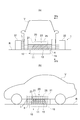
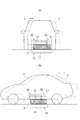
- Drawing 1 (a) is a figure showing the schematic structure which looked at the power transmission device and the foreign material detection device of the non-contact electric supply system concerning an embodiment from the front of vehicles.
- 1B is a schematic configuration of the power transmission device and the foreign object detection device of the non-contact power feeding system in FIG. 1A viewed from the side of the vehicle (schematic view of the Ib-Ib cross section when the light projecting unit is viewed from the light receiving unit).
- FIG. It is a block diagram which shows the whole structure of the non-contact electric power feeding system of FIG. It is the schematic for demonstrating the magnetic field generation
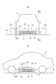
- FIG. 4A is a diagram illustrating a schematic configuration of a non-contact power feeding system viewed from the front of the vehicle when detecting the presence or absence of foreign matter.
- FIG. 4B is a diagram illustrating a schematic configuration of the non-contact power feeding system in FIG. 4A viewed from the side of the vehicle (schematic configuration of the IVb-IVb cross section when the light projecting unit is viewed from the light receiving unit).
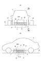
- FIG. 5A is a schematic view of a magnetic field generation region viewed from the front of the vehicle when the vehicle stops at a position deviated from the power feeding position.
- FIG. 5B is a schematic view of the magnetic field generation region viewed from the side of the vehicle when the vehicle stops at a position deviated from the power feeding position.
- FIG. 5A is a schematic view of a magnetic field generation region viewed from the front of the vehicle when the vehicle stops at a position deviated from the power feeding position.
- FIG. 5B is a schematic view of the magnetic field generation region viewed
- FIG. 6A is a diagram illustrating a schematic configuration of a non-contact power feeding system according to a modification as viewed from the front of the vehicle.
- FIG. 6B is a diagram illustrating a schematic configuration (schematic configuration of a VIb-VIb cross section when the light projecting unit is viewed from the light receiving unit) of the non-contact power feeding system in FIG. 6A viewed from the side of the vehicle.
- Fig.7 (a) is a figure which shows schematic structure which looked at the non-contact electric power feeding system which concerns on a modification from the front of the vehicle.
- FIG. 7B is a diagram showing a schematic configuration (schematic configuration of a section VIIb-VIIb when the light projecting unit is viewed from the light receiving unit) of the non-contact power feeding system in FIG. 7A viewed from the side of the vehicle. . It is the schematic for demonstrating the magnetic field generation
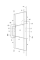
- FIG. 9A is a schematic view of the magnetic field generation region specified in consideration of the positional deviation of the vehicle as viewed from the front of the vehicle.
- FIG. 9B is a schematic view of the magnetic field generation region specified in consideration of the positional deviation of the vehicle as viewed from the side of the vehicle.
- power is supplied in a non-contact manner between a first coil device having a first coil and installed on a reference surface, and a second coil device having a second coil and mounted on a moving body.
- a foreign matter detection device for a non-contact power feeding system wherein the shape of a first coil facing surface facing the second coil device in the first coil, the size of the first coil facing surface, and the reference surface of the first coil facing surface
- a storage unit for storing first coil device information including a height position and a height position from a reference surface of a first device facing surface facing the second coil device in the first coil device, and a first in the second coil
- the magnetic field generation region is specified based on the first coil device information and the second coil device information. And in a foreign material detection apparatus, the foreign material detection part detects the presence or absence of the foreign material in a magnetic field generation region. Thereby, even if the shape etc. of the 2nd coil opposing surface differ for every moving body, a magnetic field generation area can be correctly specified according to a moving body. As a result, the foreign object detection device detects as much as possible the foreign object between the first coil device and the second coil device that does not interfere with the non-contact power supply, and the non-contact power supply may stop. Can be lowered.
- the region specifying unit is formed between the first device facing surface and the second device facing surface among the columnar or frustum-shaped intercoil regions formed between the first coil facing surface and the second coil facing surface.
- the region may be specified as a magnetic field generation region.
- the foreign object detection device can easily identify an area that greatly affects power feeding when the foreign object exists as a magnetic field generation area.
- the area specifying unit expands the outer peripheral edge of the first coil facing surface to the outside over the entire circumference by a predetermined enlargement length, and the outer peripheral edge of the second coil facing surface extends to the outside over the entire circumference.
- the height position of the first device opposing surface and the height position of the second device opposing surface The area between the two is specified as the magnetic field generation area, and the enlarged length may be a length equal to or shorter than the interval in the facing direction between the first coil facing surface and the second coil facing surface.
- the foreign object detection device uses the region including the portion where the magnetic field expanding outside is generated as the magnetic field generation region even if the portion where the magnetic field is generated between the first coil and the second coil is expanded outward. Can be easily identified.
- the foreign object detection device of the non-contact power feeding system further includes a position detection unit that detects a position in a first direction orthogonal to the facing direction of the first coil device and the second coil device in the moving body,
- the magnetic field generation region may be specified based on the first coil device information, the second coil device information, and the position of the moving body detected by the position detection unit. In this case, for example, even if the position of the first coil device and the moving body is deviated from a predetermined position, the foreign object detection device can specify the magnetic field generation region with high accuracy in consideration of this deviation. .
- the non-contact power feeding system 1 includes a power transmission device (first coil device) 10, a power reception device (second coil device) 20, and a foreign object detection device 30.
- the non-contact power supply system 1 is a system for supplying power from the power transmission device 10 to the power reception device 20 in a contactless manner.
- the power transmission device 10 is installed on a traveling road surface (reference surface, ground) R such as a parking lot, for example.
- the power receiving device 20 is mounted on a vehicle (moving body) V that is an electric vehicle, for example.
- the foreign object detection device 30 is provided on the ground.
- the non-contact power supply system 1 is configured to supply electric power to the vehicle V that has arrived at a parking lot or the like by using magnetic coupling between coils such as a magnetic resonance method or an electromagnetic induction method.
- the non-contact power feeding method is not limited to the one using magnetic coupling, and may be an electric field resonance method, for example.
- the power transmission device 10 is a device that supplies power to the power receiving device 20 by non-contact power feeding.
- the power transmission device 10 includes a power transmission coil (first coil) 11, a power transmission circuit 12, and a cover 15.
- the power transmission circuit 12 is accommodated in the cover 15.
- the power transmission coil 11 is accommodated in the cover 15 so that the upper surface 13 of the power transmission coil 11 is exposed on the upper surface of the cover 15.
- the power transmission device 10 is embedded in a recess provided on the traveling road surface R so that the upper surface is exposed. That is, the upper surface 13 of the power transmission coil 11 is exposed on the traveling road surface R.
- the upper surface 13 of the power transmission coil 11 is a surface (first coil facing surface) facing the power receiving device 20 in the power transmission coil 11.
- the upper surface 13 of the power transmission coil 11 is a surface (first device facing surface) of the power transmission device 10 that faces the power reception device 20.
- the power transmission circuit 12 generates high-frequency AC power suitable for non-contact power supply from power supplied from a power supply (not shown).
- the power transmission circuit 12 supplies AC power to the power transmission coil 11 in a state where the vehicle V is stopped in the power supply possible region.
- the power supply possible region is a range of the stop position of the vehicle V when power is supplied between the power transmission device 10 and the power reception device 20.
- the power supply possible region is determined in advance.
- the power supply possible region is determined in advance based on the power supply efficiency, for example, a region where the power supply efficiency is a predetermined value or more.
- the power transmission coil 11 generates a magnetic field by the AC power supplied from the power transmission circuit 12. This magnetic field is an alternating magnetic field that changes in a sinusoidal shape over time.
- the power receiving device 20 is a device that receives power from the power transmitting device 10 in a contactless manner.
- the power receiving device 20 includes a power receiving coil (second coil) 21 and a cover 25. As shown in FIGS. 1A and 1B, the power receiving coil 21 is accommodated in the cover 25 so that the lower surface 23 of the power receiving coil 21 is exposed on the lower surface of the cover 25.
- the power receiving device 20 is attached to the bottom surface of the vehicle body (chassis or the like) of the vehicle V between the front wheels and the rear wheels of the vehicle V so that the lower surface is exposed. That is, when the vehicle V is viewed from the traveling road surface R side, the lower surface 23 of the power receiving coil 21 is exposed.
- the lower surface 23 of the power receiving coil 21 is a surface (second coil facing surface) of the power receiving coil 21 that faces the power transmission device 10. Further, the lower surface 23 of the power receiving coil 21 is a surface (second device facing surface) of the power receiving device 20 that faces the power transmitting device 10.
- the power receiving coil 21 receives power from the power transmission device 10. Specifically, when the power receiving coil 21 is present in the alternating magnetic field generated by the power transmitting coil 11, the power receiving coil 21 generates an induced current. Thereby, the power receiving coil 21 receives AC power from the power transmitting coil 11 in a non-contact (wireless) manner. The electric power received by the power receiving coil 21 is used for charging the battery of the vehicle V through a rectifier circuit and a charging circuit.
- the foreign object detection device 30 is a device that detects a foreign object between the power transmission device 10 and the power reception device 20.
- the foreign object detection device 30 includes a light projecting unit 31, a light receiving unit 32, a foreign object detection unit 33, a region specifying unit 34, a storage unit 35, an information acquisition unit 36, and a position detection unit 37.
- the foreign object detection unit 33, the region specifying unit 34, the storage unit 35, the information acquisition unit 36, and the position detection unit 37 include, for example, a CPU (Central Processing Unit), a ROM (Read Only Memory), and a RAM (Random Access Memory). It consists of an ECU (Electronic Control Unit).
- ECU Electronic Control Unit
- the light projecting unit 31 irradiates a plurality of light beams L so as to include a region between the power receiving device 20 and the power transmitting device 10 of the vehicle V that stops in the power supplyable region.
- the region between the power receiving device 20 and the power transmitting device 10 of the vehicle V that stops in the power supply possible region is different for each vehicle V, such as the mounting height of the power receiving device 20 is different for each vehicle V (for each type of vehicle V). Different.
- the light projecting unit 31 irradiates the light beam L so as to include a region between the power receiving device 20 mounted on all the vehicles V to be fed in the non-contact power feeding system 1 and the power transmitting device 10. .
- the light projecting unit 31 irradiates the light beam L immediately before the start of power feeding between the power transmitting device 10 and the power receiving device 20 and during power feeding.
- the light receiving unit 32 detects a plurality of light beams L emitted from the light projecting unit 31.
- the light receiving unit 32 detects the irradiated light beams L so as to be able to identify which light beam L is detected.
- a light detection sensor such as a photodiode is provided for each position where each light beam L can be received.
- the storage unit 35 includes the shape of the upper surface 13 of the power transmission coil 11, the size of the upper surface 13, the height position from the traveling road surface R on the upper surface 13, and the traveling road surface R of the surface facing the power receiving device 20 in the power transmission device 10.
- the power transmission device information (first coil device information) including the height position is stored.
- the surface facing the power receiving device 20 in the power transmission device 10 is the upper surface 13 of the power transmission coil 11 in this embodiment.
- the storage unit 35 stores power transmission device information including the shape of the upper surface 13 of the power transmission coil 11, the size of the upper surface 13, and the height position of the upper surface 13 from the traveling road surface R.
- the shape of the upper surface 13 of the power transmission coil 11, the size of the upper surface 13, and the height position of the upper surface 13 from the traveling road surface R are set in advance by a designer or the like of the non-contact power feeding system 1.
- the height position of the upper surface 13 and the height position of the traveling road surface R coincide with each other.
- the information acquisition unit 36 includes the shape of the lower surface 23 of the power receiving coil 21, the size of the lower surface 23, the height position of the lower surface 23 from the traveling road surface R, and the traveling road surface R of the surface of the power receiving device 20 facing the power transmission device 10.
- the power receiving device information (second coil device information) including the height position from is acquired. Note that the surface of the power reception device 20 that faces the power transmission device 10 is the lower surface 23 of the power reception coil 21 in this embodiment. For this reason, in this embodiment, the information acquisition unit 36 acquires power receiving device information including the shape of the lower surface 23 of the power receiving coil 21, the size of the lower surface 23, and the height position of the lower surface 23 from the traveling road surface R.
- the information acquisition unit 36 may acquire the power receiving device information directly from the vehicle V via the communication device.
- the information acquisition unit 36 acquires the identification information of the vehicle V, and for each vehicle V, the power reception device corresponding to the vehicle V based on the identification information from a server or the like that stores the power reception device information and the identification information in association with each other. Information may be acquired.
- the information acquisition unit 36 may acquire the identification information from the vehicle V via the communication device, or may acquire the identification information by reading the number plate or the like of the vehicle V.
- the information acquisition unit 36 is not limited to acquiring power receiving device information from a server or the like, and may store power receiving device information and identification information in association with each vehicle V.
- the position detection unit 37 detects a position in the horizontal direction (first direction) orthogonal to the facing direction (vertical direction) of the power transmission device 10 and the power reception device 20 in the vehicle V.
- the position detection unit 37 detects the position of the vehicle V that has stopped for power feeding.
- the position detection unit 37 may acquire the position of the vehicle V measured by a GPS receiver mounted on the vehicle V.
- the position detection unit 37 may detect the position of the vehicle V using various sensors such as a magnetic field generated for position detection that is different from the magnetic field for non-contact power feeding.
- the region specifying unit 34 determines whether the upper surface 13 of the power transmission coil 11 and the lower surface 23 of the power reception coil 21 are supplied during power feeding. A magnetic field generation region X generated in the meantime is specified (estimated).
- the region specifying unit 34 three-dimensionally specifies the shape, size, and position of the magnetic field generation region X.
- the magnetic field generation region X can be, for example, a region where the strength of the magnetic field is equal to or greater than a predetermined threshold. Since the magnetic field is an alternating magnetic field, the strength of the magnetic field means, for example, an effective value.
- the region specifying unit 34 can specify the magnetic field generation region X by performing a known simulation in consideration of the power transmission device information and the power reception device information, the characteristics of the power transmission coil 11 and the power reception coil 21, and the like.
- the region specifying unit 34 may specify the magnetic field generation region X by approximation or the like.
- the region specifying unit 34 can three-dimensionally grasp the positional relationship between the upper surface 13 of the power transmission coil 11 and the lower surface 23 of the power reception coil 21 based on the power transmission device information and the power reception device information. More specifically, the region specifying unit 34 determines the position of the lower surface 23 of the power receiving coil 21 with respect to the upper surface 13 of the power transmitting coil 11 based on the position of the vehicle V detected by the position detecting unit 37, the power transmitting device information, and the power receiving device information. It can be grasped in three dimensions.
- the region specifying unit 34 may not use the position of the vehicle V detected by the position detecting unit 37.
- the region specifying unit 34 assumes that the vehicle V has stopped at a predetermined power supply position in the power supply possible region, and the power receiving coil for the upper surface 13 of the power transmitting coil 11 based on the power transmitting device information and the power receiving device information.
- the position of the lower surface 23 of 21 can be grasped three-dimensionally.
- the predetermined power feeding position is, for example, the position of the vehicle V having the best power feeding efficiency in the power feedable region, or the horizontal center position of the power transmission coil 11 and the horizontal center position of the power receiving coil 21 are vertically It may be a matching position in the direction.
- a known method can be used as a method for three-dimensionally grasping the position of the lower surface 23 of the power receiving coil 21 with respect to the upper surface 13 of the power transmitting coil 11, a known method can be used. In this case, the position detection unit 37 may be omitted.
- the area specifying unit 34 Based on the positions of the upper surface 13 of the power transmission coil 11 and the lower surface 23 of the power receiving coil 21 that are grasped three-dimensionally, the area specifying unit 34, as shown in FIG. 3, the upper surface 13 of the power transmission coil 11 and the power receiving coil 21.
- a columnar or frustum-shaped inter-coil region C1 formed between the lower surface 23 and the lower surface 23 is calculated three-dimensionally.
- the column-shaped or frustum-shaped inter-coil region C1 is a space formed by linearly connecting the outer peripheral edge of the upper surface 13 of the power transmission coil 11 and the outer peripheral edge of the lower surface 23 of the power receiving coil 21 over the entire periphery. .
- the region specifying unit 34 specifies the calculated inter-coil region C1 as the magnetic field generation region X.
- the inter-coil region C1 has a columnar shape.
- the inter-coil region C1 has various columnar shapes such as a columnar shape and a quadrangular prism shape according to the shapes of the upper surface 13 of the power transmission coil 11 and the lower surface 23 of the power receiving coil 21.
- the region C1 has a frustum shape.
- the inter-coil region C1 has various frustum shapes such as a truncated cone shape and a quadrangular frustum shape depending on the shapes of the upper surface 13 of the power transmission coil 11 and the lower surface 23 of the power reception coil 21.
- the region specifying unit 34 can also specify the magnetic field generation region X in consideration of the bulge of the portion where the magnetic field is generated.
- the region specifying unit 34 includes a power transmission side coil expansion surface 14 (enlarged first coil facing surface) in which the outer peripheral edge of the upper surface 13 of the power transmission coil 11 is expanded outward by a predetermined expansion length K over the entire circumference. calculate.
- the region specifying unit 34 calculates a power reception side coil expansion surface 24 (enlarged second coil facing surface) in which the outer peripheral edge of the lower surface 23 of the power reception coil 21 is expanded outward by an expansion length K over the entire circumference.
- the region specifying unit 34 three-dimensionally calculates a columnar or frustum-shaped inter-coil region C2 formed between the power transmission side coil expansion surface 14 and the power reception side coil expansion surface 24.
- the area specifying unit 34 can calculate the enlarged inter-coil area C2 in the same manner as the inter-coil area C1.
- the area specifying unit 34 has a height position of a surface facing the power receiving device 20 in the power transmission device 10 and a height position of a surface facing the power transmission device 10 in the power receiving device 20. Is specified as the magnetic field generation region X.
- the surface facing the power receiving device 20 in the power transmission device 10 is the upper surface 13 of the power transmission coil 11.
- the height position of the upper surface 13 of the power transmission coil 11 and the height position of the power transmission side coil enlarged surface 14 are the same.
- the surface of the power receiving device 20 that faces the power transmitting device 10 is the lower surface 23 of the power receiving coil 21.
- the region specifying unit 34 specifies the entire inter-expansion coil region C2 as the magnetic field generation region X.
- the gap in the facing direction between the upper surface 13 of the power transmission coil 11 and the lower surface 23 of the power reception coil 21 is defined as a gap length G.
- the predetermined expansion length K is set to a gap length G ⁇ P or less.
- P is a constant determined according to the coil type (circular type, solenoid type, etc.) and the coil shape (square shape, elongated rectangular shape, etc.), and in this embodiment, it is in the range of 0 to 1.
- the magnetic field generation region X is the same as the inter-coil region C1.
- a magnetic field generation region between the inter-coil region C1 and the inter-coil region C2 when the expansion length K is the gap length G by setting the expansion length K according to the spread of the location where the magnetic field is generated. X can be set.
- the region specifying unit 34 As shown in FIGS. 4A and 4B, and FIGS. 5A and 5B, the upper surface 13 of the power transmission coil 11 and the lower surface of the power reception coil 21.
- the magnetic field generation region X generated between the first and second members 23 can be specified.
- 4A and 4B and FIGS. 5A and 5B show a case where the inter-coil region C1 is specified as the magnetic field generation region X.
- FIG. 4A and 4B show the magnetic field generation region X specified by the region specifying unit 34 when the vehicle V is stopped at a predetermined power supply position in the power supply possible region. ing.
- 5 (a) and 5 (b) use the position of the vehicle V detected by the position detection unit 37 when the vehicle V is stopped at a position deviated from the power feeding position in the power feedable region.
- the magnetic field generation region X specified by the region specifying unit 34 is shown. 5A and 5B, the light receiving unit 32 and the like are omitted to show the magnetic field generation region X.
- the foreign matter detection unit 33 detects the presence or absence of foreign matter in the magnetic field generation region X specified by the region specification unit 34.
- the foreign object detection unit 33 detects the presence or absence of a foreign object based on the detection result of the light beam L in the light receiving unit 32. That is, the presence / absence of a foreign object is detected using the fact that the foreign object blocks the light beam.
- the foreign matter detection unit 33 detects a light beam L that passes through the magnetic field generation region X among the plurality of light beams L detected by the light receiving unit 32 in order to detect the presence or absence of foreign matter in the magnetic field generation region X. Based on the result, the presence or absence of foreign matter is detected.
- the foreign object detection unit 33 specifies a light beam L that passes through the magnetic field generation region X specified by the region specification unit 34 among the plurality of light beams L emitted from the light projecting unit 31 using a known technique. .
- the light beam L passing through the magnetic field generation region X is indicated by a black circle, and the light beam L passing outside the magnetic field generation region X is indicated by a white circle. .
- the foreign object detection unit 33 detects that there is a foreign object in the magnetic field generation region X when any of the light beams L passing through the magnetic field generation region X is not detected by the light receiving unit 32.
- the foreign matter detection unit 33 detects that there is no foreign matter in the magnetic field generation region X when all the light beams L passing through the magnetic field generation region X are detected by the light receiving unit 32.
- the light beam L that passes outside the magnetic field generation region X passes, for example, a region where the power supply is not affected (small influence) even if the vehicle V is blocked by the vehicle body or foreign matter is present during power supply. For this reason, the foreign matter detection unit 33 does not use the detection result of the light beam L that passes outside the magnetic field generation region X to detect the foreign matter.
- the power transmission circuit 12 stops the supply of AC power to the power transmission coil 11. Thereby, when a foreign substance exists in the magnetic field generation region X, the power supply between the power transmission device 10 and the power reception device 20 is stopped or the power supply is not started.
- the present embodiment is configured as described above, and in the foreign object detection device 30 of the non-contact power feeding system 1, based on the power transmission device information stored in the storage unit 35 and the power reception device information acquired by the information acquisition unit 36.
- the magnetic field generation region X is specified.
- the foreign matter detection unit 33 detects the presence or absence of foreign matter in the magnetic field generation region X.
- the foreign object detection device 30 prevents detection of foreign objects that do not interfere with non-contact power supply among foreign objects between the power transmission apparatus 10 and the power receiving apparatus 20, and reduces the possibility that the non-contact power supply stops. can do.
- the region specifying unit 34 can specify a columnar or frustum-shaped inter-coil region C1 formed between the upper surface 13 of the power transmission coil 11 and the lower surface 23 of the power receiving coil 21 as a magnetic field generation region.
- the foreign object detection device 30 can easily specify a region that greatly affects power supply as a magnetic field generation region X when a foreign object is present.
- the region specifying unit 34 is a columnar or frustum shape formed between a power transmission side coil enlarged surface 14 in which the upper surface 13 of the power transmission coil 11 is enlarged and a power receiving side coil enlarged surface 24 in which the lower surface 23 of the power receiving coil 21 is enlarged.
- the foreign object detection device 30 includes a region including a portion where the magnetic field expanding outward is generated even if the portion where the magnetic field is generated between the power transmission coil 11 and the power receiving coil 21 is expanded outward. X can be easily specified.
- the region specifying unit 34 specifies the magnetic field generation region X based on the position of the vehicle V detected by the position detecting unit 37 in addition to the power transmitting device information and the power receiving device information. Thereby, for example, even if the stopping position of the vehicle V is deviated from a predetermined power feeding position, the foreign object detection device 30 can specify the magnetic field generation region X with high accuracy in consideration of this deviation.
- the power transmission device 10A includes the power transmission coil 11 and the like as in the above embodiment.
- the power transmission coil 11 is accommodated in the cover 15 and is not exposed on the upper surface of the cover 15. That is, the upper surface of the power transmission coil 11 is covered with the cover 15.
- the power transmission device 10A is installed on the traveling road surface R.
- the height position of the upper surface 16 of the power transmission device 10A is higher than the height position of the traveling road surface R.
- the power receiving device 20A includes a power receiving coil 21 and the like as in the above embodiment.
- the power receiving coil 21 is accommodated in the cover 25 and is not exposed on the lower surface of the cover 25. That is, the lower surface of the power receiving coil 21 is covered with the cover 25.
- the storage unit 35 is opposed to the shape of the upper surface 13 of the power transmission coil 11, the size of the upper surface 13, the height position from the traveling road surface R on the upper surface 13, and the power reception device 20A in the power transmission device 10A.
- the power transmission device information (first coil device information) including the height position of the surface (first device facing surface) from the traveling road surface R is stored. Note that the surface facing the power receiving device 20A in the power transmission device 10A is the upper surface 16 of the cover 15 when the power transmission device 10A is used.
- the storage unit 35 has a shape of the upper surface 13 of the power transmission coil 11, a size of the upper surface 13, a height position from the traveling road surface R on the upper surface 13, and a height position from the traveling road surface R on the upper surface 16 of the cover 15. Is remembered.
- the information acquisition unit 36 includes the shape of the lower surface 23 of the power receiving coil 21, the size of the lower surface 23, the height position of the lower surface 23 from the traveling road surface R, and the power transmitting device 10A in the power receiving device 20A.
- Power receiving device information (second coil device information) including a height position of the facing surface (second device facing surface) from the traveling road surface R is acquired. Note that the surface of the power receiving device 20A that faces the power transmitting device 10A is the lower surface 26 of the cover 25 when the power receiving device 20A is used.
- the information acquisition part 36 is the shape of the lower surface 23 of the receiving coil 21, the magnitude
- Power receiving device information including is acquired.
- the region specifying unit 34 and the cover 16 of the power reception device 20A and the upper surface 16 of the cover 15 of the power transmission device 10A are supplied.
- the magnetic field generation region X generated between the lower surface 26 of the 25 is specified.
- the region specifying unit 34 can specify the magnetic field generation region X by performing a known simulation in consideration of the power transmission device information and the power reception device information, the characteristics of the power transmission coil 11 and the power reception coil 21, and the like.
- the region specifying unit 34 may specify the magnetic field generation region X generated between the power transmitting device 10A and the power receiving device 20A by approximation or the like. Based on the power transmission device information and the power reception device information, the region specifying unit 34 three-dimensionally determines the positional relationship among the upper surface 13 of the power transmission coil 11, the lower surface 23 of the power reception coil 21, the upper surface 16 of the cover 15, and the lower surface 26 of the cover 25. Can grasp. More specifically, the region specifying unit 34 receives the power receiving coil with respect to the upper surface 13 of the power transmission coil 11 and the upper surface 16 of the cover 15 based on the position of the vehicle V detected by the position detecting unit 37, the power transmitting device information, and the power receiving device information. The positions of the lower surface 23 of 21 and the lower surface 26 of the cover 25 can be grasped three-dimensionally.
- the region specifying unit 34 may not use the position of the vehicle V detected by the position detecting unit 37. In this case, the region specifying unit 34 assumes that the vehicle V has stopped at a predetermined power supply position in the power supply possible region, and based on the power transmission device information and the power reception device information, the upper surface 13 and the cover of the power transmission coil 11. The positions of the lower surface 23 of the power receiving coil 21 and the lower surface 26 of the cover 25 with respect to the upper surface 16 of 15 can be grasped three-dimensionally.
- the region specifying unit 34 three-dimensionally calculates the inter-coil region C1 formed between the upper surface 13 of the power transmission coil 11 and the lower surface 23 of the power receiving coil 21 as in the above embodiment.
- the region specifying unit 34 specifies a region between the upper surface 16 of the cover 15 and the lower surface 26 of the cover 25 as the magnetic field generation region X in the inter-coil region C1.
- the region specifying unit 34 can also specify the magnetic field generation region X in consideration of the bulge of the portion where the magnetic field is generated. Specifically, the region specifying unit 34 three-dimensionally calculates the inter-expansion coil region C2 formed between the power transmission side coil expansion surface 14 and the power reception side coil expansion surface 24, as in the above embodiment. To do.
- the area specifying unit 34 has a height position of a surface facing the power receiving device 20A in the power transmitting device 10A and a height position of a surface facing the power transmitting device 10A in the power receiving device 20A. Is specified as the magnetic field generation region X.
- the surface facing the power receiving device 20 ⁇ / b> A in the power transmission device 10 ⁇ / b> A is the upper surface 16 of the cover 15.
- the surface of power reception device 20 ⁇ / b> A that faces power transmission device 10 ⁇ / b> A is lower surface 26 of cover 25.
- the region specifying unit 34 determines a region between the height position of the upper surface 16 of the cover 15 and the height position of the lower surface 26 of the cover 25 in the inter-expansion coil region C2. Identify as X.
- the region specification unit 34 excludes the inside of the cover 15 and the inside of the cover 25 and generates the magnetic field generation region X generated between the power transmission device 10A and the power reception device 20A. Can be specified with high accuracy. Since the inside of the cover 15 and the inside of the cover 25 are excluded in the magnetic field generation region X, it is possible to prevent the cover 15 and the cover 25 from being detected as a foreign object when the foreign object detection unit 33 detects the foreign object. .
- the region specifying unit 34 uses the position of the vehicle V detected by the position detection unit 37 or a predetermined power feeding position of the lower surface 23 of the power receiving coil 21 with respect to the upper surface 13 of the power transmitting coil 11. The position etc. were grasped and the magnetic field generation region X was specified.
- the area specifying unit 34 does not use the position of the vehicle V detected by the position detection unit 37 or a predetermined power feeding position, and depends on where the vehicle V stops in the power feedable area.
- the magnetic field generation region X that is not to be used may be specified. In this case, for example, as shown in FIGS.
- the region specifying unit 34 may specify the magnetic field generation region X in consideration of the maximum positional deviation in the power supplyable region. Good. That is, the area specifying unit 34 specifies a magnetic field generation area when it is assumed that the vehicle V stops at an arbitrary position in the power supply possible area, and sets the magnetic field generation area X to include all the specified magnetic field generation areas. You may specify. In this case, the position detection unit 37 may be omitted.
- the vehicle V indicated by the alternate long and short dash line and the magnetic field generation region generated between the power transmission coil 11 and the power reception coil 21 are one end in the width direction of the vehicle V in the power supply possible region. The state when it has shifted to the maximum side is shown. The vehicle indicated by the broken line, and the magnetic field generation region generated between the power transmission coil 11 and the power reception coil 21 are in a state where they are shifted to the maximum in the other end side in the width direction of the vehicle V within the power supply possible region. Show. Similarly, in FIG. 9B, the vehicle V indicated by the alternate long and short dash line and the magnetic field generation region generated between the power transmission coil 11 and the power reception coil 21 are one of the front and rear directions of the vehicle V in the power supply possible region.
- the state when it has shifted to the maximum on the end side is shown.
- the vehicle indicated by the broken line, the magnetic field generation region generated between the power transmission coil 11 and the power reception coil 21, etc. are in a state where they are shifted to the maximum in the other end side in the front-rear direction of the vehicle V within the power supply possible region.
- the region specifying unit 34 specifies a region including all of these magnetic field generation regions indicated by the alternate long and short dash line and the broken line as the magnetic field generation region X.
- both the power transmission device and the power reception device may not be the power transmission device 10A and the power reception device 20A in which the coil is covered with a cover as shown in FIG.
- one of the power transmission device and the power reception device may be the power transmission device 10 ⁇ / b> A or the power reception device 20 ⁇ / b> A in which a coil is covered with a cover.
- the region specifying unit 34 can specify the magnetic field generation region X as described with reference to FIGS. 3 and 8.
- the foreign matter detection unit 33 detects the presence or absence of foreign matter in the magnetic field generation region X based on the detection result of the light beam L in the light receiving unit 32, but the presence or absence of foreign matter based on information other than the detection result of the light receiving unit 32. May be detected.
- the foreign matter detection unit 33 may detect the presence or absence of foreign matter in the magnetic field generation region X by performing known image processing on an image taken by an imaging device such as a stereo camera.
- the foreign material detection part 33 may detect the presence or absence of the foreign material in the magnetic field generation region X based on the detection result of the laser irradiated and reflected by the foreign material.
- the power transmission coil 11 and the power reception coil 21 are, for example, circular type coils.
- the circular type coil includes a conductive wire wound in a spiral shape when viewed along the opposing direction of the power transmission coil 11 and the power reception coil 21. This conducting wire is wound into a rectangle or a circle, for example.
- the power transmission coil 11 and the power reception coil 21 may be solenoid type coils.
- power is transmitted from the power transmission device 10 installed on the traveling road surface R (ground) to the vehicle V side, but power may be transmitted from the vehicle V to the traveling road surface R side (ground side).
- power is supplied to the vehicle V from the ground side, but power can be supplied to a moving body other than the vehicle V.
- the moving body may be a ship, for example.
- a mounting surface of a power transmission coil of a power transmission device provided in a port or the like can be used as a reference surface.
- the height position of the surface on the power transmission device side of the power transmission coil of the power reception device mounted on the ship can be set to the height position from the reference surface at the power feeding position.
- the reference plane is a vertical plane, and the horizontal distance from the reference plane is used instead of the height position.
- the moving body is not limited to the vehicle V and the ship, and may be, for example, a motorcycle, a bicycle, a train, or an airplane.
- the power receiving device 20 may be attached to the bottom surface of the vehicle body of the vehicle V in front of the front wheel of the vehicle V or behind the rear wheel of the vehicle V.
- the power transmission circuit 12 may not be accommodated in the cover 15 but may be accommodated in a separate housing.
- foreign matter detection device of the non-contact power feeding system of the present disclosure foreign matter that does not interfere with non-contact power feeding among foreign matters between coil devices is not detected as much as possible, and the possibility that non-contact power feeding stops is reduced. be able to.
- Non-contact electric power feeding system 10 Power transmission apparatus (1st coil apparatus) 11 Power transmission coil (first coil) 13 Upper surface of power transmission coil (first coil facing surface, first device facing surface) 14 Power transmission side coil enlarged surface (enlarged first coil facing surface) 16 Upper surface of cover (first device facing surface) 20 Power receiving device (second coil device) 21 Power receiving coil (second coil) 23 Lower surface of receiving coil (second coil facing surface, second device facing surface) 24 Power receiving side coil enlarged surface (enlarged second coil facing surface) 26 Lower surface of cover (surface facing second device) DESCRIPTION OF SYMBOLS 30 Foreign material detection apparatus 33 Foreign material detection part 34 Area
Landscapes
- Engineering & Computer Science (AREA)
- Power Engineering (AREA)
- Computer Networks & Wireless Communication (AREA)
- Transportation (AREA)
- Mechanical Engineering (AREA)
- Charge And Discharge Circuits For Batteries Or The Like (AREA)
- Electric Propulsion And Braking For Vehicles (AREA)
Abstract
非接触給電システムの異物検出装置は、基準面に設置された第1コイル装置と、移動体に搭載された第2コイル装置との間で非接触で給電する。異物検出装置は、第1コイル対向面の形状、大きさ、及び基準面からの高さ位置、並びに第1装置対向面の高さ位置を含む第1コイル装置情報を記憶する記憶部と、第2コイル対向面の形状、大きさ、及び高さ位置、並びに第2装置対向面の高さ位置を含む第2コイル装置情報を取得する情報取得部と、第1コイル装置情報と第2コイル装置情報とに基づいて、給電時に第1装置対向面と第2装置対向面との間に発生する磁場発生領域を特定する領域特定部と、特定された磁場発生領域内の異物の有無を検出する異物検出部と、を備える。
Description
本開示は、非接触給電システムの異物検出装置に関する。
例えば、車両に搭載されたコイル装置と、地上に設置されたコイル装置との間で非接触で給電する非接触給電システムがある。このようなシステムが、例えば特許文献1に記載されている。
特許文献1に記載されたシステムでは、車両に搭載されたコイル装置の給電面に照射された光を検出することにより、車両に搭載されたコイル装置と、地上に設置されたコイル装置との間の異物を検出している。
例えば、車両等の移動体においては、移動体に搭載されたコイル装置が有するコイルの形状及び大きさ、並びに取り付け高さ位置が移動体ごとに(移動体の種類ごとに)異なることがある。この場合、給電時にコイル装置間に生じる磁場発生領域の形状も様々な形状となり、磁場発生領域外の異物を検出してしまうことがある。非接触給電は磁場発生領域内の磁場を介して行われるので、磁場発生領域内の異物は磁場に影響して非接触給電に支障を及ぼすが、磁場発生領域外の異物は非接触給電に支障を及ぼさず、磁場発生領域外に異物が存在しても正常に非接触給電することができる。すなわち、異物が磁場発生領域内に存在する場合は非接触給電を停止するなどの対応をする必要があるが、異物が磁場発生領域外に存在する場合は、正常に非接触給電できる。しかし、異物検出において、磁場発生領域内と磁場発生領域外を識別していない場合、磁場発生領域外の異物が検出された場合であっても、非接触給電を停止するなどの対応をする必要があり、非接触給電が停止する可能性が高くなり、不便である。
そこで、本開示は、コイル装置間の異物のうち、非接触給電に支障を及ぼさない異物はできるだけ検出しないようにし、非接触給電が停止する可能性を低くすることができる非接触給電システムの異物検出装置を説明する。
本開示の一態様は、第1コイルを有すると共に基準面に設置された第1コイル装置と、第2コイルを有すると共に移動体に搭載された第2コイル装置との間で非接触で給電する非接触給電システムの異物検出装置であって、第1コイルにおける第2コイル装置と対向する第1コイル対向面の形状、第1コイル対向面の大きさ、第1コイル対向面の基準面からの高さ位置、及び第1コイル装置における第2コイル装置と対向する第1装置対向面の基準面からの高さ位置を含む第1コイル装置情報を記憶する記憶部と、第2コイルにおける第1コイル装置と対向する第2コイル対向面の形状、第2コイル対向面の大きさ、第2コイル対向面の基準面からの高さ位置、及び第2コイル装置における第1コイル装置と対向する第2装置対向面の基準面からの高さ位置を含む第2コイル装置情報を取得する情報取得部と、第1コイル装置情報と第2コイル装置情報とに基づいて、給電時に第1装置対向面と第2装置対向面との間に発生する磁場発生領域を特定する領域特定部と、特定された磁場発生領域内の異物の有無を検出する異物検出部と、を備える。
本開示の一態様によれば、コイル装置間の異物のうち、非接触給電に支障を及ぼさない異物はできるだけ検出しないようにし、非接触給電が停止する可能性を低くすることができる。
本開示の一態様は、第1コイルを有すると共に基準面に設置された第1コイル装置と、第2コイルを有すると共に移動体に搭載された第2コイル装置との間で非接触で給電する非接触給電システムの異物検出装置であって、第1コイルにおける第2コイル装置と対向する第1コイル対向面の形状、第1コイル対向面の大きさ、第1コイル対向面の基準面からの高さ位置、及び第1コイル装置における第2コイル装置と対向する第1装置対向面の基準面からの高さ位置を含む第1コイル装置情報を記憶する記憶部と、第2コイルにおける第1コイル装置と対向する第2コイル対向面の形状、第2コイル対向面の大きさ、第2コイル対向面の基準面からの高さ位置、及び第2コイル装置における第1コイル装置と対向する第2装置対向面の基準面からの高さ位置を含む第2コイル装置情報を取得する情報取得部と、第1コイル装置情報と第2コイル装置情報とに基づいて、給電時に第1装置対向面と第2装置対向面との間に発生する磁場発生領域を特定する領域特定部と、特定された磁場発生領域内の異物の有無を検出する異物検出部と、を備える。
この非接触給電システムの異物検出装置では、第1コイル装置情報と第2コイル装置情報とに基づいて磁場発生領域が特定される。そして、異物検出装置では、異物検出部において、磁場発生領域内の異物の有無が検出される。これにより、移動体ごとに第2コイル対向面の形状等が異なっていても、移動体に応じて磁場発生領域を正しく特定することができる。これにより、異物検出装置は、第1コイル装置と第2コイル装置との間の異物のうち、非接触給電に支障を及ぼさない異物はできるだけ検出しないようにし、非接触給電が停止する可能性を低くすることができる。
領域特定部は、第1コイル対向面と第2コイル対向面との間に形成される柱状又は錐台状のコイル間領域のうち、第1装置対向面と第2装置対向面との間の領域を磁場発生領域として特定してもよい。この場合、異物検出装置は、異物が存在している場合に給電に大きく影響を与える領域を、磁場発生領域として容易に特定することができる。
領域特定部は、第1コイル対向面の外周縁を全周にわたって外側に所定の拡大長さ拡大した拡大第1コイル対向面と、第2コイル対向面の外周縁を全周にわたって外側に拡大長さ拡大した拡大第2コイル対向面との間に形成される柱状又は錐台状の拡大コイル間領域のうち、第1装置対向面の高さ位置と第2装置対向面の高さ位置との間の領域を磁場発生領域として特定し、拡大長さは、第1コイル対向面と第2コイル対向面との対向方向の間隔以下の長さであってもよい。この場合、異物検出装置は、第1コイルと第2コイルとの間で磁場の発生する箇所が外側に膨らむ場合であっても、外側に膨らむ磁場の発生する箇所を含む領域を磁場発生領域として容易に特定することができる。
非接触給電システムの異物検出装置は、移動体における、第1コイル装置と第2コイル装置との対向方向に直交する第1方向の位置を検出する位置検出部を更に備え、領域特定部は、第1コイル装置情報と、第2コイル装置情報と、位置検出部で検出された移動体の位置とに基づいて、磁場発生領域を特定してもよい。この場合、異物検出装置は、例えば、第1コイル装置と移動体との位置が予め定められた位置からずれていたとしても、このずれも考慮して精度良く磁場発生領域を特定することができる。
以下、本開示の実施形態について図面を参照しながら説明する。なお、図面の説明において同一の要素には同一の符号を付し、重複する説明を省略する。
図1及び図2に示すように、非接触給電システム1は、送電装置(第1コイル装置)10と、受電装置(第2コイル装置)20と、異物検出装置30とを備えている。非接触給電システム1は、送電装置10から受電装置20に非接触で給電するためのシステムである。送電装置10は、例えば駐車場等の走行路面(基準面、地上)Rに設置されている。受電装置20は、例えば電気自動車である車両(移動体)Vに搭載されている。異物検出装置30は、地上に設けられている。非接触給電システム1は、駐車場等に到着した車両Vに対し、磁界共鳴方式又は電磁誘導方式等のコイル間の磁気結合を利用して、電力を供給するように構成されている。なお、非接触給電方式は、磁気結合を利用したものに限らず、例えば、電界共鳴方式であってもよい。
送電装置10は、非接触給電により電力を受電装置20に供給する装置である。送電装置10は、送電コイル(第1コイル)11、送電回路12、及びカバー15を備えている。送電回路12は、カバー15内に収容されている。図1(a)及び図1(b)に示すように、送電コイル11は、カバー15の上面において送電コイル11の上面13が露出するようにカバー15内に収容されている。送電装置10は、上面が露出するように、走行路面Rに設けられた凹部内に埋め込まれている。すなわち、走行路面Rにおいて送電コイル11の上面13が露出している。
このように、送電コイル11の上面13とは、送電コイル11における受電装置20と対向する面(第1コイル対向面)である。また、送電コイル11の上面13とは、送電装置10における受電装置20と対向する面(第1装置対向面)である。
送電回路12は、図示しない電源等より供給された電力から非接触給電に適した高周波の交流電力を生成する。送電回路12は、車両Vが給電可能領域内に停車した状態で、送電コイル11に交流電力を供給する。ここで、給電可能領域とは、送電装置10と受電装置20との間で給電を行うときの車両Vの停車位置の範囲である。給電可能領域は、予め定められている。給電可能領域は、例えば、給電効率が所定値以上の領域である等、給電効率に基づいて予め定められている。送電コイル11は、送電回路12から供給された交流電力によって磁場を発生させる。この磁場は時間的に正弦波状に変化する交流磁場である。
受電装置20は、送電装置10から非接触で電力を受け取る装置である。受電装置20は、受電コイル(第2コイル)21、及びカバー25を備えている。図1(a)及び図1(b)に示すように、受電コイル21は、カバー25の下面において受電コイル21の下面23が露出するようにカバー25内に収容されている。受電装置20は、下面が露出するように、車両Vの前輪と後輪との間において、車両Vの車体(シャーシ等)の底面に取り付けられている。すなわち、車両Vを走行路面R側から見た場合、受電コイル21の下面23が露出している。
このように、受電コイル21の下面23とは、受電コイル21における送電装置10と対向する面(第2コイル対向面)である。また、受電コイル21の下面23とは、受電装置20における送電装置10と対向する面(第2装置対向面)である。
受電コイル21は、送電装置10から電力を受け取る。具体的には、送電コイル11で発生した交流磁場中に受電コイル21が存在することによって、受電コイル21は誘導電流を発生させる。これにより、受電コイル21は、非接触(ワイヤレス)で送電コイル11から交流電力を受け取る。受電コイル21が受け取った電力は、整流回路及び充電回路等を介して車両Vのバッテリの充電などに利用される。
異物検出装置30は、送電装置10と受電装置20との間の異物を検出する装置である。具体的には、異物検出装置30は、投光部31、受光部32、異物検出部33、領域特定部34、記憶部35、情報取得部36、及び位置検出部37を備えている。異物検出部33、領域特定部34、記憶部35、情報取得部36、及び位置検出部37は、例えばCPU(Central Processing Unit)、ROM(Read Only Memory)、及び、RAM(Random Access Memory)を備えるECU(Electronic Control Unit)によって構成されている。
投光部31は、給電可能領域に停車する車両Vの受電装置20と送電装置10との間の領域を含むように、複数本の光ビームLを照射する。なお、車両Vごと(車両Vの種類ごと)に受電装置20の取り付け高さが異なるなど、給電可能領域に停車する車両Vの受電装置20と送電装置10との間の領域は、車両Vごとに異なる。このため、投光部31は、非接触給電システム1において給電対象とするすべての車両Vに搭載された受電装置20と、送電装置10との間の領域を含むように光ビームLを照射する。投光部31は、送電装置10と受電装置20との間での給電開始の直前、及び給電中に光ビームLを照射する。
受光部32は、投光部31から照射された複数本の光ビームLを検出する。受光部32は、照射された複数本の光ビームLを、いずれの光ビームLが検出されたかを識別可能に検出する。例えば、それぞれの光ビームLを受光しうる位置ごとに、フォトダイオードなどの光検出センサが設けられている。
記憶部35は、送電コイル11の上面13の形状、上面13の大きさ、上面13における走行路面Rからの高さ位置、及び、送電装置10における受電装置20と対向する面の走行路面Rからの高さ位置を含む送電装置情報(第1コイル装置情報)を記憶する。なお、送電装置10における受電装置20と対向する面とは、本実施形態では、送電コイル11の上面13である。このため、本実施形態において記憶部35は、送電コイル11の上面13の形状、上面13の大きさ、及び上面13における走行路面Rからの高さ位置を含む送電装置情報を記憶している。送電コイル11の上面13の形状、上面13の大きさ、及び上面13の走行路面Rからの高さ位置は、非接触給電システム1の設計者等によって予め設定されている。本実施形態では、上面13の高さ位置と走行路面Rの高さ位置とは一致している。
情報取得部36は、受電コイル21の下面23の形状、下面23の大きさ、下面23の走行路面Rからの高さ位置、及び、受電装置20における送電装置10と対向する面の走行路面Rからの高さ位置を含む受電装置情報(第2コイル装置情報)を取得する。なお、受電装置20における送電装置10と対向する面とは、本実施形態では、受電コイル21の下面23である。このため、本実施形態において情報取得部36は、受電コイル21の下面23の形状、下面23の大きさ、下面23の走行路面Rからの高さ位置を含む受電装置情報を取得する。
ここで、情報取得部36は、受電装置情報を通信装置を介して車両Vから直接取得してもよい。例えば、情報取得部36は、車両Vの識別情報を取得し、車両Vごとに受電装置情報と識別情報とを対応付けて記憶するサーバ等から識別情報に基づいて当該車両Vに対応する受電装置情報を取得してもよい。この場合、情報取得部36は、車両Vから通信装置を介して識別情報を取得してもよく、車両Vのナンバープレート等を読み取ることで識別情報を取得してもよい。また、情報取得部36は、サーバ等から受電装置情報を取得することに限定されず、車両Vごとに受電装置情報と識別情報とを対応付けて記憶していてもよい。
位置検出部37は、車両Vにおける、送電装置10と受電装置20との対向方向(上下方向)に直交する水平方向(第1方向)の位置を検出する。位置検出部37は、給電を行うために停車した車両Vの位置を検出する。例えば、位置検出部37は、車両Vに搭載されたGPS受信装置で測位された車両Vの位置を取得してもよい。例えば、位置検出部37は、非接触給電のための磁場とは異なる、位置検出用に発生させた磁場を用いる等、種々のセンサ等を用いて車両Vの位置を検出してもよい。
領域特定部34は、記憶部35が記憶する送電装置情報と、情報取得部36で取得された受電装置情報とに基づいて、給電時に送電コイル11の上面13と受電コイル21の下面23との間に発生する磁場発生領域Xを特定(推定)する。領域特定部34は、磁場発生領域Xの形状、大きさ、及び位置を三次元的に特定する。磁場発生領域Xは、例えば、磁場の強さが所定の閾値以上の領域とすることができる。磁場は交流磁場であるので、磁場の強さとは、たとえば実効値の意味である。領域特定部34は、送電装置情報及び受電装置情報、並びに送電コイル11及び受電コイル21の特性等を考慮して周知のシミュレーションを行うことで磁場発生領域Xを特定することができる。
また、領域特定部34は、磁場発生領域Xを近似等を行うことで特定してもよい。領域特定部34は、送電装置情報及び受電装置情報に基づいて、送電コイル11の上面13と受電コイル21の下面23との位置関係を三次元的に把握することができる。より詳細には、領域特定部34は、位置検出部37で検出された車両Vの位置、送電装置情報及び受電装置情報に基づいて送電コイル11の上面13に対する受電コイル21の下面23の位置を三次元的に把握することができる。
なお、領域特定部34は、位置検出部37で検出された車両Vの位置を用いなくてもよい。この場合、領域特定部34は、車両Vが給電可能領域内の予め定められた給電位置に停車したと仮定して、送電装置情報及び受電装置情報に基づいて送電コイル11の上面13に対する受電コイル21の下面23の位置を三次元的に把握することができる。予め定められた給電位置とは、例えば、給電可能領域内において最も給電効率が良い車両Vの位置、或いは、送電コイル11の水平方向の中心位置と受電コイル21の水平方向の中心位置とが上下方向において一致する位置であってもよい。送電コイル11の上面13に対する受電コイル21の下面23の位置を三次元的に把握する手法については、周知の方法を用いることができる。この場合、位置検出部37を省略してもよい。
領域特定部34は、三次元的に把握された送電コイル11の上面13及び受電コイル21の下面23の位置に基づいて、図3に示すように、送電コイル11の上面13と受電コイル21の下面23との間に形成される柱状又は錐台状のコイル間領域C1を三次元的に算出する。柱状又は錐台状のコイル間領域C1とは、送電コイル11の上面13の外周縁と、受電コイル21の下面23の外周縁とを全周にわたって直線的につなぐことによって形成される空間である。領域特定部34は、算出したコイル間領域C1を磁場発生領域Xとして特定する。
ここで、送電コイル11の上面13の形状及び大きさと、受電コイル21の下面23の形状及び大きさとが同じである場合、コイル間領域C1は柱状となる。この場合、コイル間領域C1は、送電コイル11の上面13及び受電コイル21の下面23の形状に応じて、円柱状、四角柱状など種々の柱状となる。また、送電コイル11の上面13の形状と受電コイル21の下面23の形状とが同じであり、送電コイル11の上面13の大きさと受電コイル21の下面23の大きさとが互いに異なる場合、コイル間領域C1は錐台状となる。この場合、コイル間領域C1は、送電コイル11の上面13及び受電コイル21の下面23の形状に応じて、円錐台状、四角錐台状など種々の錐台状となる。
また、給電時に送電コイル11の上面13と受電コイル21の下面23との間に発生する磁場は、コイル間領域C1の外側にも発生する場合がある。このため、領域特定部34は、この磁場が発生する箇所の膨らみを考慮して磁場発生領域Xを特定することもできる。具体的には、領域特定部34は、送電コイル11の上面13の外周縁を全周にわたって外側に所定の拡大長さKだけ拡大した送電側コイル拡大面14(拡大第1コイル対向面)を算出する。同様に、領域特定部34は、受電コイル21の下面23の外周縁を全周にわたって外側に拡大長さKだけ拡大した受電側コイル拡大面24(拡大第2コイル対向面)を算出する。領域特定部34は、送電側コイル拡大面14と受電側コイル拡大面24との間に形成される柱状又は錐台状の拡大コイル間領域C2を三次元的に算出する。領域特定部34は、拡大コイル間領域C2をコイル間領域C1と同様に算出することができる。
領域特定部34は、算出した拡大コイル間領域C2のうち、送電装置10における受電装置20と対向する面の高さ位置と、受電装置20における送電装置10と対向する面との高さ位置との間の領域を、磁場発生領域Xとして特定する。ここで、本実施形態において、送電装置10における受電装置20と対向する面とは、送電コイル11の上面13である。送電コイル11の上面13の高さ位置と、送電側コイル拡大面14の高さ位置とは同じである。同様に、受電装置20における送電装置10と対向する面とは、受電コイル21における下面23である。受電コイル21における下面23の高さ位置と、受電側コイル拡大面24とは同じ高さ位置である。このため、本実施形態において、領域特定部34は、拡大コイル間領域C2の全体を磁場発生領域Xとして特定する。
ここで、送電コイル11の上面13と受電コイル21の下面23との対向方向の間隔を、ギャップ長Gとする。ギャップ長Gが増加すると磁場が発生する箇所の膨らみ量も増加するので、所定の拡大長さKは、ギャップ長G×P以下の長さとする。ここで、Pは、コイルの形式(サーキュラー型、ソレノイド型など)及びコイル形状(正方形状、細長い長方形状など)に応じて決まる定数であり、本実施形態においては、0以上1以下の範囲内の値であることが多い。このため、拡大長さKを0(ゼロ)とした場合には、磁場発生領域Xはコイル間領域C1と同じとなる。磁場が発生する箇所の広がりに応じて拡大長さKを設定することで、コイル間領域C1と、拡大長さKをギャップ長Gとしたときの拡大コイル間領域C2との間で磁場発生領域Xを設定することができる。
これにより、領域特定部34は、図4(a)及び図4(b)、並びに図5(a)及び図5(b)に示すように、送電コイル11の上面13と受電コイル21の下面23との間に発生する磁場発生領域Xを特定することができる。図4(a)及び図4(b)、並びに図5(a)及び図5(b)では、コイル間領域C1を磁場発生領域Xとして特定した場合を示している。また、図4(a)及び図4(b)は、車両Vが給電可能領域内の予め定められた給電位置に停車している場合において、領域特定部34が特定した磁場発生領域Xを示している。図5(a)及び図5(b)は、給電可能領域内において車両Vが給電位置からずれた位置に停車している場合に、位置検出部37で検出された車両Vの位置を用いて領域特定部34が特定した磁場発生領域Xを示している。なお、図5(a)及び図5(b)では、磁場発生領域Xを示すために、受光部32等を省略している。
異物検出部33は、領域特定部34で特定された磁場発生領域X内の異物の有無を検出する。本実施形態において、異物検出部33は、受光部32における光ビームLの検出結果に基づいて異物の有無を検出する。すなわち、異物が光ビームを遮ることを利用して異物の有無を検出する。また、異物検出部33は、磁場発生領域X内の異物の有無を検出するために、受光部32で検出される複数の光ビームLのうち、磁場発生領域X内を通る光ビームLの検出結果に基づいて異物の有無を検出する。異物検出部33は、周知の技術を用いて、投光部31から照射された複数の光ビームLのうち、領域特定部34で特定された磁場発生領域X内を通る光ビームLを特定する。
図4(a)及び図4(b)に示す例では、磁場発生領域X内を通る光ビームLを黒丸で示し、磁場発生領域X外を通る光ビームLを白抜きの丸で示している。異物検出部33は、磁場発生領域X内を通る光ビームLのいずれかが受光部32によって検出されない場合、磁場発生領域X内に異物が有りと検出する。異物検出部33は、磁場発生領域X内を通る光ビームLが受光部32によってすべて検出されている場合、磁場発生領域X内に異物が無いと検出する。
磁場発生領域X外を通る光ビームLは、例えば、車両Vの車体に遮られたり、給電の際に異物が存在しても給電に影響を及ぼさない(影響が小さい)領域を通っている。このため、異物検出部33は、磁場発生領域X外を通る光ビームLの検出結果については、異物を検出するために使用しない。
異物検出部33によって異物が検出された場合、送電回路12は、送電コイル11への交流電力の供給を停止する。これにより、磁場発生領域X内に異物が存在する場合には、送電装置10と受電装置20との間の給電が停止する又は給電が開始されない。
本実施形態は以上のように構成され、非接触給電システム1の異物検出装置30では、記憶部35に記憶された送電装置情報と、情報取得部36で取得された受電装置情報とに基づいて磁場発生領域Xが特定される。そして、異物検出装置30では、異物検出部33において、磁場発生領域X内の異物の有無が検出される。これにより、車両Vごとに受電コイル21の下面23の形状等が異なっていても、車両Vに応じて磁場発生領域Xを正しく特定することができる。これにより、異物検出装置30は、送電装置10と受電装置20との間の異物のうち、非接触給電に支障を及ぼさない異物はできるだけ検出しないようにし、非接触給電が停止する可能性を低くすることができる。
領域特定部34は、送電コイル11の上面13と受電コイル21の下面23との間に形成される柱状又は錐台状のコイル間領域C1を磁場発生領域として特定することができる。この場合、異物検出装置30は、異物が存在している場合に給電に大きく影響を与える領域を、磁場発生領域Xとして容易に特定することができる。
領域特定部34は、送電コイル11の上面13を拡大した送電側コイル拡大面14と、受電コイル21の下面23を拡大した受電側コイル拡大面24との間に形成される柱状又は錐台状の拡大コイル間領域C2を磁場発生領域Xとして特定することができる。この場合、異物検出装置30は、送電コイル11と受電コイル21との間で磁場が発生する箇所が外側に膨らむ場合であっても、外側に膨らむ磁場が発生する箇所を含む領域を磁場発生領域Xとして容易に特定することができる。
領域特定部34は、送電装置情報及び受電装置情報に加え、位置検出部37で検出された車両Vの位置に基づいて磁場発生領域Xを特定する。これにより、異物検出装置30は、例えば、車両Vの停車位置が予め定められた給電位置からずれていたとしても、このずれも考慮して精度良く磁場発生領域Xを特定することができる。
次に、変形例として、送電装置10及び受電装置20に代えて、これらとは構成が異なる送電装置及び受電装置を用いた場合における磁場発生領域Xの特定の方法について説明する。送電装置10とは異なる構成の送電装置として、例えば、図6(a)及び図6(b)に示す送電装置10Aがある。送電装置10Aは、上記実施形態と同様に送電コイル11等を備えている。送電装置10Aにおいて、送電コイル11は、カバー15内に収容されており、カバー15の上面において露出していない。すなわち、送電コイル11の上面がカバー15によって覆われている。なお、図6(a)及び図6(b)に示す例では、送電装置10Aは走行路面R上に設置されている。送電装置10Aの上面16の高さ位置は、走行路面Rの高さ位置よりも高くなっている。
受電装置20とは異なる構成の受電装置として、例えば、図7(a)及び図7(b)に示す受電装置20Aがある。受電装置20Aは、上記実施形態と同様に受電コイル21等を備えている。受電装置20Aにおいて、受電コイル21は、カバー25内に収容されており、カバー25の下面において露出していない。すなわち、受電コイル21の下面がカバー25によって覆われている。
以下、送電装置10A及び受電装置20Aのように、送電コイル11及び受電コイル21がカバー15及びカバー25によってそれぞれ覆われている場合における磁場発生領域Xの特定の方法について、図8を用いて説明する。
送電装置10Aを用いる場合、記憶部35は、送電コイル11の上面13の形状、上面13の大きさ、上面13における走行路面Rからの高さ位置、及び、送電装置10Aにおける受電装置20Aと対向する面(第1装置対向面)の走行路面Rからの高さ位置を含む送電装置情報(第1コイル装置情報)を記憶する。なお、送電装置10Aにおける受電装置20Aと対向する面とは、送電装置10Aを用いる場合には、カバー15の上面16である。このため、記憶部35は、送電コイル11の上面13の形状、上面13の大きさ、上面13における走行路面Rからの高さ位置、及びカバー15の上面16における走行路面Rからの高さ位置を記憶している。
受電装置20Aを用いる場合、情報取得部36は、受電コイル21の下面23の形状、下面23の大きさ、下面23の走行路面Rからの高さ位置、及び、受電装置20Aにおける送電装置10Aと対向する面(第2装置対向面)の走行路面Rからの高さ位置を含む受電装置情報(第2コイル装置情報)を取得する。なお、受電装置20Aにおける送電装置10Aと対向する面とは、受電装置20Aを用いる場合には、カバー25の下面26である。このため、情報取得部36は、受電コイル21の下面23の形状、下面23の大きさ、下面23の走行路面Rからの高さ位置、カバー25の下面26における走行路面Rからの高さ位置を含む受電装置情報を取得する。
領域特定部34は、記憶部35が記憶する送電装置情報と、情報取得部36で取得された受電装置情報とに基づいて、給電時に送電装置10Aのカバー15の上面16と受電装置20Aのカバー25の下面26との間に発生する磁場発生領域Xを特定する。領域特定部34は、送電装置情報及び受電装置情報、並びに送電コイル11及び受電コイル21の特性等を考慮して周知のシミュレーションを行うことで磁場発生領域Xを特定することができる。
また、領域特定部34は、送電装置10Aと受電装置20Aとの間に発生する磁場発生領域Xを近似等を行うことで特定してもよい。領域特定部34は、送電装置情報及び受電装置情報に基づいて、送電コイル11の上面13、受電コイル21の下面23、カバー15の上面16、及びカバー25の下面26の位置関係を三次元的に把握することができる。より詳細には、領域特定部34は、位置検出部37で検出された車両Vの位置、送電装置情報及び受電装置情報に基づいて、送電コイル11の上面13及びカバー15の上面16に対する受電コイル21の下面23及びカバー25の下面26の位置を三次元的に把握することができる。
なお、領域特定部34は、位置検出部37で検出された車両Vの位置を用いなくてもよい。この場合、領域特定部34は、車両Vが給電可能領域内の予め定められた給電位置に停車したと仮定して、送電装置情報及び受電装置情報に基づいて、送電コイル11の上面13及びカバー15の上面16に対する受電コイル21の下面23及びカバー25の下面26の位置を三次元的に把握することができる。
領域特定部34は、上記の実施形態と同様に、送電コイル11の上面13と受電コイル21の下面23との間に形成されるコイル間領域C1を三次元的に算出する。領域特定部34は、コイル間領域C1のうち、カバー15の上面16とカバー25の下面26との間の領域を磁場発生領域Xとして特定する。
また、給電時に送電コイル11の上面13と受電コイル21の下面23との間に発生する磁場は、コイル間領域C1の外側にも発生する場合がある。このため、領域特定部34は、この磁場が発生する箇所の膨らみを考慮して磁場発生領域Xを特定することもできる。具体的には、領域特定部34は、上記の実施形態と同様に、送電側コイル拡大面14と受電側コイル拡大面24との間に形成される拡大コイル間領域C2を三次元的に算出する。
領域特定部34は、算出した拡大コイル間領域C2のうち、送電装置10Aにおける受電装置20Aと対向する面の高さ位置と、受電装置20Aにおける送電装置10Aと対向する面との高さ位置との間の領域を、磁場発生領域Xとして特定する。ここで、本実施形態において、送電装置10Aにおける受電装置20Aと対向する面とは、カバー15の上面16である。同様に、受電装置20Aにおける送電装置10Aと対向する面とは、カバー25における下面26である。このため、本実施形態において、領域特定部34は、拡大コイル間領域C2のうち、カバー15の上面16の高さ位置とカバー25の下面26の高さ位置との間の領域を磁場発生領域Xとして特定する。
送電装置10A及び受電装置20Aを用いる場合、カバー15内及びカバー25内には異物が侵入しない。このため、カバー15の内部(カバー15自身を含む)及びカバー25の内部(カバー25自身を含む)は異物の検出対象外とすることができる。上述した方法によって磁場発生領域Xを特定することで、領域特定部34は、カバー15の内部及びカバー25の内部を除外して、送電装置10Aと受電装置20Aとの間に生じる磁場発生領域Xを精度良く特定することができる。磁場発生領域Xではカバー15の内部及びカバー25の内部が除外されているため、異物検出部33が異物の検出を行う際に、カバー15及びカバー25を異物として検出してしまうことを防止できる。
以上、本開示の実施形態及び変形例について説明したが、本開示は、上記実施形態に限定されるものではない。例えば、上記の例では、領域特定部34は、位置検出部37で検出された車両Vの位置又は予め定められた給電位置を用いて、送電コイル11の上面13に対する受電コイル21の下面23の位置等を把握し、磁場発生領域Xを特定した。これに対し、領域特定部34は、位置検出部37で検出された車両Vの位置又は予め定められた給電位置を用いずに、車両Vが給電可能領域内のどの場所に停車するかに依存しない磁場発生領域Xを特定してもよい。この場合、領域特定部34は、例えば、図9(a)及び図9(b)に示すように、給電可能領域内での最大の位置ずれを考慮して磁場発生領域Xを特定してもよい。すなわち、領域特定部34は、車両Vが給電可能領域内の任意の位置で停車したと仮定したときの磁場発生領域を特定し、特定したすべての磁場発生領域を含むように磁場発生領域Xを特定してもよい。この場合、位置検出部37が省略されてもよい。
なお、図9(a)において、一点鎖線で示す車両V、及び送電コイル11と受電コイル21との間に発生する磁場発生領域等は、給電可能領域内において車両Vの幅方向の一方の端部側に最大までずれたときの状態を示している。破線で示す車両、及び送電コイル11と受電コイル21との間に発生する磁場発生領域等は、給電可能領域内において車両Vの幅方向の他方の端部側に最大までずれたときの状態を示している。同様に、図9(b)において、一点鎖線で示す車両V、及び送電コイル11と受電コイル21との間に発生する磁場発生領域等は、給電可能領域内において車両Vの前後方向の一方の端部側に最大までずれたときの状態を示している。破線で示す車両、及び送電コイル11と受電コイル21との間に発生する磁場発生領域等は、給電可能領域内において車両Vの前後方向の他方の端部側に最大までずれたときの状態を示している。領域特定部34は、一点鎖線及び破線で示すこれらの磁場発生領域のすべてを含む領域を磁場発生領域Xとして特定する。
また、送電装置及び受電装置のうち、両方が、図8に示すようにコイルがカバーに覆われた送電装置10A及び受電装置20Aでなくてもよい。図6及び図7に示すように、送電装置及び受電装置のうち、いずれか一方が、コイルがカバーに覆われた送電装置10A又は受電装置20Aであってもよい。この場合(図6及び図7に示す場合)も、図3及び図8を用いて説明したのと同様に、領域特定部34は、磁場発生領域Xを特定することができる。
異物検出部33は、受光部32における光ビームLの検出結果に基づいて磁場発生領域X内の異物の有無の検出を行ったが、受光部32の検出結果以外の情報に基づいて異物の有無の検出を行ってもよい。例えば、異物検出部33は、ステレオカメラ等の撮像装置で撮像された画像に対して周知の画像処理を行うことにより、磁場発生領域X内の異物の有無を検出してもよい。また、異物検出部33は、レーザーを照射し、異物によって反射するレーザーの検出結果に基づいて、磁場発生領域X内の異物の有無を検出してもよい。
送電コイル11及び受電コイル21は、例えば、サーキュラー型のコイルである。サーキュラー型のコイルは、送電コイル11と受電コイル21との対向方向に沿って見たときに、渦巻状に巻かれた導線とを含む。この導線は、例えば、矩形または円形に巻かれている。或いは、送電コイル11及び受電コイル21は、ソレノイド型のコイルであってもよい。
上記の例では、走行路面R(地上)に設置された送電装置10から車両V側へ送電したが、車両Vから走行路面R側(地上側)に送電してもよい。
また、上記の例では、地上側から車両Vに給電したが、車両V以外の移動体に給電することもできる。移動体として、例えば、船であってもよい。船に給電する場合、例えば、港等に設けられた送電装置の送電コイルの取り付け面を基準面とすることができる。また、船に搭載された受電装置の送電コイルにおける送電装置側の面の高さ位置などは、給電位置における基準面からの高さ位置とすることができる。例えば、船に側方から給電する場合は、基準面は垂直な面であり、高さ位置のかわりに、基準面からの水平方向距離を用いる。また、移動体は、車両V及び船に限定されず、例えばバイク、自転車、電車、飛行機であってもよい。
受電装置20は、車両Vの前輪より前方、もしくは車両Vの後輪より後方において、車両Vの車体の底面に取り付けられていてもよい。送電回路12は、カバー15内に収容されておらず、別筐体に収容されていてもよい。
本開示の非接触給電システムの異物検出装置によれば、コイル装置間の異物のうち、非接触給電に支障を及ぼさない異物はできるだけ検出しないようにし、非接触給電が停止する可能性を低くすることができる。
1 非接触給電システム
10 送電装置(第1コイル装置)
11 送電コイル(第1コイル)
13 送電コイルの上面(第1コイル対向面、第1装置対向面)
14 送電側コイル拡大面(拡大第1コイル対向面)
16 カバーの上面(第1装置対向面)
20 受電装置(第2コイル装置)
21 受電コイル(第2コイル)
23 受電コイルの下面(第2コイル対向面、第2装置対向面)
24 受電側コイル拡大面(拡大第2コイル対向面)
26 カバーの下面(第2装置対向面)
30 異物検出装置
33 異物検出部
34 領域特定部
35 記憶部
36 情報取得部
37 位置検出部
C1 コイル間領域
C2 拡大コイル間領域
R 走行路面(基準面)
V 車両(移動体)
X 磁場発生領域
Claims (4)
- 第1コイルを有すると共に基準面に設置された第1コイル装置と、第2コイルを有すると共に移動体に搭載された第2コイル装置との間で非接触で給電する非接触給電システムの異物検出装置であって、
前記第1コイルにおける前記第2コイル装置と対向する第1コイル対向面の形状、前記第1コイル対向面の大きさ、前記第1コイル対向面の前記基準面からの高さ位置、及び前記第1コイル装置における前記第2コイル装置と対向する第1装置対向面の前記基準面からの高さ位置を含む第1コイル装置情報を記憶する記憶部と、
前記第2コイルにおける前記第1コイル装置と対向する第2コイル対向面の形状、前記第2コイル対向面の大きさ、前記第2コイル対向面の前記基準面からの高さ位置、及び前記第2コイル装置における前記第1コイル装置と対向する第2装置対向面の前記基準面からの高さ位置を含む第2コイル装置情報を取得する情報取得部と、
前記第1コイル装置情報と前記第2コイル装置情報とに基づいて、前記給電時に前記第1装置対向面と前記第2装置対向面との間に発生する磁場発生領域を特定する領域特定部と、
特定された前記磁場発生領域内の異物の有無を検出する異物検出部と、を備える非接触給電システムの異物検出装置。 - 前記領域特定部は、前記第1コイル対向面と前記第2コイル対向面との間に形成される柱状又は錐台状のコイル間領域のうち、前記第1装置対向面と前記第2装置対向面との間の領域を前記磁場発生領域として特定する、請求項1に記載の非接触給電システムの異物検出装置。
- 前記領域特定部は、前記第1コイル対向面の外周縁を全周にわたって外側に所定の拡大長さ拡大した拡大第1コイル対向面と、前記第2コイル対向面の外周縁を全周にわたって外側に前記拡大長さ拡大した拡大第2コイル対向面との間に形成される柱状又は錐台状の拡大コイル間領域のうち、前記第1装置対向面の高さ位置と前記第2装置対向面の高さ位置との間の領域を前記磁場発生領域として特定し、
前記拡大長さは、前記第1コイル対向面と前記第2コイル対向面との対向方向の間隔以下の長さである、請求項1に記載の非接触給電システムの異物検出装置。 - 前記移動体における、前記第1コイル装置と前記第2コイル装置との対向方向に直交する第1方向の位置を検出する位置検出部を更に備え、
前記領域特定部は、前記第1コイル装置情報と、前記第2コイル装置情報と、前記位置検出部で検出された前記移動体の位置とに基づいて、前記磁場発生領域を特定する、請求項1~3のいずれか一項に記載の非接触給電システムの異物検出装置。
Priority Applications (2)
| Application Number | Priority Date | Filing Date | Title |
|---|---|---|---|
| EP18753800.4A EP3584906B1 (en) | 2017-02-14 | 2018-02-13 | Foreign matter detection device for non-contact power supply system |
| US16/340,397 US11011944B2 (en) | 2017-02-14 | 2018-02-13 | Foreign matter detection device for non-contact power supply system |
Applications Claiming Priority (2)
| Application Number | Priority Date | Filing Date | Title |
|---|---|---|---|
| JP2017-025007 | 2017-02-14 | ||
| JP2017025007A JP6819339B2 (ja) | 2017-02-14 | 2017-02-14 | 非接触給電システムの異物検出装置 |
Publications (1)
| Publication Number | Publication Date |
|---|---|
| WO2018151096A1 true WO2018151096A1 (ja) | 2018-08-23 |
Family
ID=63169973
Family Applications (1)
| Application Number | Title | Priority Date | Filing Date |
|---|---|---|---|
| PCT/JP2018/004885 WO2018151096A1 (ja) | 2017-02-14 | 2018-02-13 | 非接触給電システムの異物検出装置 |
Country Status (4)
| Country | Link |
|---|---|
| US (1) | US11011944B2 (ja) |
| EP (1) | EP3584906B1 (ja) |
| JP (1) | JP6819339B2 (ja) |
| WO (1) | WO2018151096A1 (ja) |
Cited By (1)
| Publication number | Priority date | Publication date | Assignee | Title |
|---|---|---|---|---|
| CN112689578A (zh) * | 2018-09-19 | 2021-04-20 | 纬湃科技有限责任公司 | 用于感应充电装置的用于检测活体的方法和装置 |
Families Citing this family (3)
| Publication number | Priority date | Publication date | Assignee | Title |
|---|---|---|---|---|
| KR102332797B1 (ko) * | 2017-01-03 | 2021-11-30 | 현대자동차주식회사 | 전기차 무선 전력 전송 시스템에서 이동식 레이저를 이용한 이물질 검출 장치 |
| JP7054834B2 (ja) * | 2017-07-20 | 2022-04-15 | パナソニックIpマネジメント株式会社 | 電極ユニット、送電装置、受電装置、電子機器、移動体、および無線電力伝送システム |
| JP2022025563A (ja) * | 2020-07-29 | 2022-02-10 | Tdk株式会社 | 送電装置、ワイヤレス電力伝送システム及び情報通信システム |
Citations (6)
| Publication number | Priority date | Publication date | Assignee | Title |
|---|---|---|---|---|
| JP2014113018A (ja) * | 2012-11-09 | 2014-06-19 | Nissan Motor Co Ltd | 非接触給電装置 |
| JP2014121126A (ja) * | 2012-12-14 | 2014-06-30 | Nissan Motor Co Ltd | 非接触給電システム |
| JP2014150628A (ja) * | 2013-01-31 | 2014-08-21 | Toyota Motor Corp | 受電装置、送電装置および電力伝送システム |
| JP2015008552A (ja) * | 2011-10-31 | 2015-01-15 | パナソニック株式会社 | 非接触充電装置 |
| JP2016158410A (ja) * | 2015-02-25 | 2016-09-01 | 本田技研工業株式会社 | 受電体及び該受電体を備える車両 |
| JP2016167973A (ja) * | 2015-03-07 | 2016-09-15 | ヒュンダイ アメリカ テクニカル センター,インコーポ−レイテッド | 相互運用可能な電気自動車無線充電方法およびシステム |
Family Cites Families (21)
| Publication number | Priority date | Publication date | Assignee | Title |
|---|---|---|---|---|
| JPH07236204A (ja) | 1994-02-22 | 1995-09-05 | Hitachi Ltd | 電気自動車の充電システムおよび充電方法 |
| JP5021948B2 (ja) | 2006-03-30 | 2012-09-12 | 三菱重工業株式会社 | 障害物検知装置及びエネルギー供給装置並びにエネルギー供給システム |
| JP5494130B2 (ja) | 2010-03-31 | 2014-05-14 | アイシン・エィ・ダブリュ株式会社 | 車両用充電支援装置、車両用充電支援方法、コンピュータプログラム |
| JP5666355B2 (ja) | 2011-03-15 | 2015-02-12 | 長野日本無線株式会社 | 非接触型電力伝送装置 |
| JP5691863B2 (ja) | 2011-06-09 | 2015-04-01 | トヨタ自動車株式会社 | 受電装置、車両、送電装置、および非接触給電システム |
| JP5244946B2 (ja) | 2011-07-20 | 2013-07-24 | パナソニック株式会社 | 給電装置 |
| JP2013046492A (ja) | 2011-08-24 | 2013-03-04 | Panasonic Corp | 給電装置 |
| JP2013223397A (ja) | 2012-04-19 | 2013-10-28 | Toyota Industries Corp | 非接触充電異物侵入検知装置および方法 |
| JP5757273B2 (ja) | 2012-05-18 | 2015-07-29 | トヨタ自動車株式会社 | 異物検出装置、受電装置およびそれを備える車両、送電装置、ならびに電力伝送システム |
| JP5708563B2 (ja) | 2012-06-04 | 2015-04-30 | トヨタ自動車株式会社 | 受電装置およびそれを備える車両、送電装置、ならびに電力伝送システム |
| JP2014090601A (ja) | 2012-10-31 | 2014-05-15 | Nissan Motor Co Ltd | 非接触給電装置 |
| JP2014107915A (ja) | 2012-11-27 | 2014-06-09 | Nissan Motor Co Ltd | 非接触給電システム |
| JP6085988B2 (ja) | 2013-02-14 | 2017-03-01 | トヨタ自動車株式会社 | 受電装置および送電装置 |
| JP2014207749A (ja) | 2013-04-11 | 2014-10-30 | トヨタ自動車株式会社 | 受電装置およびそれを備える車両、送電装置、ならびに電力伝送システム |
| JP2014230299A (ja) | 2013-05-17 | 2014-12-08 | 株式会社東芝 | 異物検出装置および非接触電力伝送装置 |
| JP6478450B2 (ja) | 2013-09-13 | 2019-03-06 | 株式会社テクノバ | 金物異物の検知可能な非接触給電装置とその金物異物検知方法 |
| JP2015095960A (ja) | 2013-11-12 | 2015-05-18 | 株式会社豊田自動織機 | 送電機器及び非接触電力伝送装置 |
| JP6343292B2 (ja) | 2014-02-13 | 2018-06-13 | 株式会社東芝 | 非接触送電装置、非接触受電装置、及び非接触送受電システム |
| GB2525239A (en) * | 2014-04-17 | 2015-10-21 | Bombardier Transp Gmbh | Object detection system and method for detecting foreign objects in an inductive power transfer system |
| JP6342711B2 (ja) | 2014-05-20 | 2018-06-13 | 株式会社テクノバ | 異物検知機能を備えた非接触給電装置 |
| US9829599B2 (en) * | 2015-03-23 | 2017-11-28 | Schneider Electric USA, Inc. | Sensor and method for foreign object detection in induction electric charger |
-
2017
- 2017-02-14 JP JP2017025007A patent/JP6819339B2/ja active Active
-
2018
- 2018-02-13 WO PCT/JP2018/004885 patent/WO2018151096A1/ja unknown
- 2018-02-13 US US16/340,397 patent/US11011944B2/en active Active
- 2018-02-13 EP EP18753800.4A patent/EP3584906B1/en active Active
Patent Citations (6)
| Publication number | Priority date | Publication date | Assignee | Title |
|---|---|---|---|---|
| JP2015008552A (ja) * | 2011-10-31 | 2015-01-15 | パナソニック株式会社 | 非接触充電装置 |
| JP2014113018A (ja) * | 2012-11-09 | 2014-06-19 | Nissan Motor Co Ltd | 非接触給電装置 |
| JP2014121126A (ja) * | 2012-12-14 | 2014-06-30 | Nissan Motor Co Ltd | 非接触給電システム |
| JP2014150628A (ja) * | 2013-01-31 | 2014-08-21 | Toyota Motor Corp | 受電装置、送電装置および電力伝送システム |
| JP2016158410A (ja) * | 2015-02-25 | 2016-09-01 | 本田技研工業株式会社 | 受電体及び該受電体を備える車両 |
| JP2016167973A (ja) * | 2015-03-07 | 2016-09-15 | ヒュンダイ アメリカ テクニカル センター,インコーポ−レイテッド | 相互運用可能な電気自動車無線充電方法およびシステム |
Non-Patent Citations (1)
| Title |
|---|
| See also references of EP3584906A4 * |
Cited By (2)
| Publication number | Priority date | Publication date | Assignee | Title |
|---|---|---|---|---|
| CN112689578A (zh) * | 2018-09-19 | 2021-04-20 | 纬湃科技有限责任公司 | 用于感应充电装置的用于检测活体的方法和装置 |
| US11979033B2 (en) | 2018-09-19 | 2024-05-07 | Vitesco Technologies GmbH | Method and device for detecting living objects for inductive charging devices |
Also Published As
| Publication number | Publication date |
|---|---|
| US20190273402A1 (en) | 2019-09-05 |
| JP2018133888A (ja) | 2018-08-23 |
| EP3584906A1 (en) | 2019-12-25 |
| JP6819339B2 (ja) | 2021-01-27 |
| EP3584906A4 (en) | 2021-01-13 |
| EP3584906B1 (en) | 2022-05-11 |
| US11011944B2 (en) | 2021-05-18 |
Similar Documents
| Publication | Publication Date | Title |
|---|---|---|
| WO2018151096A1 (ja) | 非接触給電システムの異物検出装置 | |
| US10351006B2 (en) | Inductive power transfer for transferring electric energy to a vehicle | |
| US9840152B2 (en) | Apparatus for inductive power transmission | |
| US10279692B2 (en) | Electricity supply device and electricity reception device | |
| JP5838262B2 (ja) | 送電装置 | |
| US9477893B2 (en) | Positioning system and method for positioning a vehicle | |
| CN105052013B (zh) | 非接触供电装置用的异物检测装置和方法 | |
| US10199882B2 (en) | Object detection system and method for detecting foreign objects in an inductive power transfer system | |
| JP5440621B2 (ja) | 非接触給電装置 | |
| KR20120097480A (ko) | 전기에너지 유도전이장치 | |
| KR20170027770A (ko) | 유도 충전 시스템의 작동 장치 및 작동 방법 | |
| US9857495B2 (en) | Apparatus for checking for a presence of an electrically conductive body, and charging system | |
| US11325485B2 (en) | Coil device | |
| JP6306867B2 (ja) | 駐車支援システム及びワイヤレス給電システム | |
| JP2015113600A (ja) | 駐車支援システム及びワイヤレス給電システム | |
| JP6006857B2 (ja) | 送電装置 | |
| JP2015100154A (ja) | 非接触電力伝送システム | |
| JP6375750B2 (ja) | 非接触送受電システム |
Legal Events
| Date | Code | Title | Description |
|---|---|---|---|
| 121 | Ep: the epo has been informed by wipo that ep was designated in this application |
Ref document number: 18753800 Country of ref document: EP Kind code of ref document: A1 |
|
| NENP | Non-entry into the national phase |
Ref country code: DE |
|
| ENP | Entry into the national phase |
Ref document number: 2018753800 Country of ref document: EP Effective date: 20190916 |