WO2018150947A1 - 光ファイバケーブル - Google Patents
光ファイバケーブル Download PDFInfo
- Publication number
- WO2018150947A1 WO2018150947A1 PCT/JP2018/003976 JP2018003976W WO2018150947A1 WO 2018150947 A1 WO2018150947 A1 WO 2018150947A1 JP 2018003976 W JP2018003976 W JP 2018003976W WO 2018150947 A1 WO2018150947 A1 WO 2018150947A1
- Authority
- WO
- WIPO (PCT)
- Prior art keywords
- optical fiber
- inclusion
- cross
- sheath
- fiber cable
- Prior art date
Links
- 239000013307 optical fiber Substances 0.000 title claims abstract description 209
- 239000000463 material Substances 0.000 claims description 29
- 239000000835 fiber Substances 0.000 description 13
- 230000005540 biological transmission Effects 0.000 description 9
- 238000004804 winding Methods 0.000 description 9
- 239000000470 constituent Substances 0.000 description 6
- 230000008602 contraction Effects 0.000 description 6
- 230000002950 deficient Effects 0.000 description 6
- 238000011156 evaluation Methods 0.000 description 6
- XLYOFNOQVPJJNP-UHFFFAOYSA-N water Substances O XLYOFNOQVPJJNP-UHFFFAOYSA-N 0.000 description 6
- 239000004743 Polypropylene Substances 0.000 description 4
- 238000010521 absorption reaction Methods 0.000 description 4
- 230000003139 buffering effect Effects 0.000 description 4
- 229920001155 polypropylene Polymers 0.000 description 4
- 238000004519 manufacturing process Methods 0.000 description 3
- 230000004048 modification Effects 0.000 description 3
- 238000012986 modification Methods 0.000 description 3
- 229920005989 resin Polymers 0.000 description 3
- 239000011347 resin Substances 0.000 description 3
- 239000004698 Polyethylene Substances 0.000 description 2
- 229920006231 aramid fiber Polymers 0.000 description 2
- 230000008859 change Effects 0.000 description 2
- 230000000694 effects Effects 0.000 description 2
- 239000005038 ethylene vinyl acetate Substances 0.000 description 2
- 229920006244 ethylene-ethyl acrylate Polymers 0.000 description 2
- 239000002657 fibrous material Substances 0.000 description 2
- 229920001200 poly(ethylene-vinyl acetate) Polymers 0.000 description 2
- 229920000728 polyester Polymers 0.000 description 2
- -1 polyethylene Polymers 0.000 description 2
- 229920000573 polyethylene Polymers 0.000 description 2
- 229920000098 polyolefin Polymers 0.000 description 2
- 241000239290 Araneae Species 0.000 description 1
- 239000004677 Nylon Substances 0.000 description 1
- 229910000831 Steel Inorganic materials 0.000 description 1
- 230000009471 action Effects 0.000 description 1
- 239000002390 adhesive tape Substances 0.000 description 1
- 239000011248 coating agent Substances 0.000 description 1
- 238000000576 coating method Methods 0.000 description 1
- 229920001577 copolymer Polymers 0.000 description 1
- 230000001351 cycling effect Effects 0.000 description 1
- 238000005516 engineering process Methods 0.000 description 1
- 239000005042 ethylene-ethyl acrylate Substances 0.000 description 1
- 239000011521 glass Substances 0.000 description 1
- 239000003365 glass fiber Substances 0.000 description 1
- 239000002184 metal Substances 0.000 description 1
- 229920001778 nylon Polymers 0.000 description 1
- 230000002093 peripheral effect Effects 0.000 description 1
- 239000004800 polyvinyl chloride Substances 0.000 description 1
- 239000010959 steel Substances 0.000 description 1
Images
Classifications
-
- G—PHYSICS
- G02—OPTICS
- G02B—OPTICAL ELEMENTS, SYSTEMS OR APPARATUS
- G02B6/00—Light guides; Structural details of arrangements comprising light guides and other optical elements, e.g. couplings
- G02B6/44—Mechanical structures for providing tensile strength and external protection for fibres, e.g. optical transmission cables
- G02B6/4401—Optical cables
- G02B6/441—Optical cables built up from sub-bundles
- G02B6/4411—Matrix structure
-
- G—PHYSICS
- G02—OPTICS
- G02B—OPTICAL ELEMENTS, SYSTEMS OR APPARATUS
- G02B6/00—Light guides; Structural details of arrangements comprising light guides and other optical elements, e.g. couplings
- G02B6/44—Mechanical structures for providing tensile strength and external protection for fibres, e.g. optical transmission cables
- G02B6/4401—Optical cables
- G02B6/4429—Means specially adapted for strengthening or protecting the cables
- G02B6/443—Protective covering
- G02B6/4432—Protective covering with fibre reinforcements
- G02B6/4433—Double reinforcement laying in straight line with optical transmission element
Definitions
- the present invention relates to an optical fiber cable.
- the present application claims priority based on Japanese Patent Application No. 2017-029056 filed in Japan on February 20, 2017, the contents of which are incorporated herein by reference.
- an optical fiber cable as shown in Patent Document 1 is known.
- the optical fiber cable includes a buffer material disposed in the center, a plurality of optical fibers disposed around the buffer material, and a sheath that accommodates the buffer material and the plurality of optical fibers therein.
- a buffer material absorbs the external force applied to the optical fiber cable, thereby preventing the optical fiber from being influenced by the external force.
- a plurality of optical fibers may be bundled to form an optical fiber unit, and the plurality of optical fiber units may be accommodated in a sheath in a twisted state.
- a force tilting back force
- the optical fiber unit moves in the sheath by the twisting force, the optical fiber unit cannot be kept twisted.
- the twisting force is increased, and the movement of the optical fiber unit as described above is more likely to occur.
- an optical fiber cable includes a plurality of optical fiber units each having a plurality of optical fibers, and a fibrous shape extending along a longitudinal direction in which the optical fiber unit extends.
- a cross-sectional view comprising: a core configured by wrapping inclusions in a press roll; a sheath that accommodates the core therein; and a pair of strength members embedded in the sheath with the core interposed therebetween.
- the total value of the cross-sectional areas of the plurality of optical fibers is Sf
- the total value of the cross-sectional areas of the inclusions is Sb
- the cross-sectional area of the inner space of the sheath is Sc
- the cross-sectional area of the presser winding is Sw
- 0.16 ⁇ Sb / Sf 0.25
- the movement of the optical fiber unit in the optical fiber cable can be suppressed.
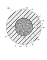
- an optical fiber cable 100 includes a core 20 having a plurality of optical fiber units 10, a sheath 55 that accommodates the core 20 therein, and a pair of strength members 56 (tension members) embedded in the sheath 55. ) And a pair of filaments 57.
- the optical fiber unit 10 extends along the central axis O.
- the direction along the central axis O is called the longitudinal direction.
- a cross section of the optical fiber cable 100 orthogonal to the central axis O is referred to as a cross section.
- a direction intersecting with the central axis O is referred to as a radial direction, and a direction around the central axis O is referred to as a circumferential direction.
- the sheath 55 is formed in a cylindrical shape centered on the central axis O.
- the material of the sheath 55 is a polyolefin (PO) such as polyethylene (PE), polypropylene (PP), ethylene ethyl acrylate copolymer (EEA), ethylene vinyl acetate copolymer (EVA), ethylene propylene copolymer (EP). ) Resin, polyvinyl chloride (PVC), etc. can be used.
- PO polyolefin
- PE polyethylene
- PP polypropylene
- EOA ethylene ethyl acrylate copolymer
- EVA ethylene vinyl acetate copolymer
- EP ethylene propylene copolymer
- PVC polyvinyl chloride
- the filament 57 As a material of the filament 57, a cylindrical rod made of PP or nylon can be used. Alternatively, the filament 57 may be formed by a yarn (yarn) obtained by twisting fibers such as PP and polyester, and the filament 57 may be provided with water absorption. The pair of filaments 57 are arranged with the core 20 sandwiched in the radial direction. In addition, the number of the line bodies 57 embedded in the sheath 55 may be 1 or 3 or more.
- a metal wire such as a steel wire
- a tensile fiber such as an aramid fiber
- FRP tensile fiber
- the pair of strength members 56 are disposed with the core 20 sandwiched in the radial direction. Further, the pair of strength members 56 are arranged at equal intervals from the core 20 in the radial direction.
- the number of strength members 56 embedded in the sheath 55 may be 1 or 3 or more.
- a pair of protrusions 58 extending along the longitudinal direction are formed on the outer peripheral surface of the sheath 55.
- the protrusion 58 and the linear body 57 are arrange
- the protrusion 58 serves as a mark when the sheath 55 is incised to take out the filament 57.
- the plurality of optical fiber units 10 are divided into two layers, ie, a radially inner layer and a radially outer layer.
- the optical fiber unit 10 located on the radially inner side is formed in a fan shape
- the optical fiber unit 10 located on the radially outer side is formed in a quadrangle.
- the binding material 2 is formed in a thin and long string shape by using a resin having high flexibility. For this reason, even if the optical fiber 1 is in a state of being bundled with the binding material 2, the optical fiber 1 is appropriately moved to an empty space in the sheath 55 while deforming the binding material 2. Therefore, the cross-sectional shape of the optical fiber unit 10 in an actual product may not be as shown in FIG. Moreover, the cross-sectional shape of the inclusion 3a is not limited to the illustrated elliptical shape. The inclusion 3a is appropriately moved to a vacant space between the plurality of optical fiber units 10 while changing the cross-sectional shape. Therefore, the cross-sectional shape of the inclusion 3a is not arranged as shown in FIG. 1, and for example, the inclusions 3a adjacent to each other may be integrated.
- the presser winding 54 may be formed of a material having water absorption, such as a water absorbing tape.
- the optical fiber unit 10 is a so-called intermittent adhesive tape core.
- the intermittently bonded tape core has a plurality of optical fibers 1.
- the plurality of optical fibers 1 are bonded to each other so as to spread in a mesh shape (spider web shape) when pulled in a direction orthogonal to the longitudinal direction.
- one optical fiber 1 is bonded to the optical fiber 1 adjacent on one side and the other optical fiber 1 adjacent on the other side at different positions in the longitudinal direction.
- the adjacent optical fibers 1 are bonded to each other at a certain interval in the longitudinal direction.
- the aspect of the optical fiber unit 10 is not limited to the intermittently bonded tape core wire, and may be changed as appropriate.
- the optical fiber unit 10 may be one in which a plurality of optical fibers 1 are simply bundled with a binding material 2.
- the inclusion 3a is formed of a fibrous material made of polyester fiber, aramid fiber, glass fiber or the like.
- the plurality of optical fiber units 10 and the inclusions 3a are wrapped by the presser winding 54 in a state of being twisted in an SZ shape.
- the optical fiber unit 10 and the inclusion 3a may be spirally twisted together without being limited to the SZ shape.
- the inclusion 3a may be a yarn having water absorbency. In this case, the waterproof performance inside the optical fiber cable 100 can be enhanced.
- the inclusion 3 a is sandwiched between two optical fiber units 10 in the circumferential direction in a cross-sectional view. Thereby, the inclusion 3a is in contact with the plurality of optical fiber units 10.
- the binding material 2 has an elongated string shape, and is wound around the bundle of optical fibers 1 in a spiral shape, for example. For this reason, the part of the optical fiber 1 that is not covered with the string-like binding material 2 partially contacts the inclusion 3a.
- the optical fiber 1 usually has a structure in which a coating material such as a resin is coated around a bare optical fiber formed of glass. For this reason, the surface of the optical fiber 1 is smooth, and the friction coefficient when the optical fibers 1 are in contact with each other is relatively small.
- the inclusion 3a is formed of a fibrous material, and the surface thereof is less smooth than the optical fiber 1. For this reason, the friction coefficient when the inclusion 3a contacts the optical fiber 1 is larger than the friction coefficient when the optical fibers 1 contact each other.
- the inclusion 3a so as to be sandwiched between the plurality of optical fiber units 10, it is possible to increase the frictional resistance when the optical fiber units 10 move relative to each other. Thereby, the movement of the optical fiber unit 10 in the optical fiber cable 100 can be suppressed. Furthermore, by arranging the inclusion 3a so as to be sandwiched between the optical fiber units 10, when the external force acts on the optical fiber cable 100, the inclusion 3a functions as a buffer material, and the optical fiber 1 It is possible to suppress the local side pressure from acting.
- vibration may be applied to the optical fiber cable 100 having such a configuration, or a temperature change may occur.
- the optical fiber cable 100 is required to make it difficult for the optical fiber unit 10 to move within the sheath 55 and to increase the transmission loss of the optical fiber 1.
- the amount of movement of the optical fiber unit 10 is required to be within a predetermined range even when a twisting-back force due to the optical fiber unit 10 and the inclusion 3a being twisted together in an SZ shape or a spiral shape acts. .
- the inventors of the present application adjust the filling amount of the inclusions 3a in the space in the sheath 55 and the filling amount of the inclusions 3a with respect to the filling amount of the optical fiber 1, thereby achieving excellent light that satisfies the above requirements. It has been found that a fiber cable 100 can be obtained.
- specific examples will be shown and described in detail.
- an optical fiber unit 10 is formed by bundling intermittently bonded tape cores with a binding material 2.
- the plurality of optical fiber units 10 were co-winded with water-absorbing yarns as inclusions 3a, and in a state where they were SZ twisted, the core 20 was formed by wrapping with a presser winding 54.
- the optical fiber cable 100 as shown in FIG. 1 was created by accommodating this core 20 in the sheath 55.
- the elastic modulus of the yarn which is the inclusion 3a was 1000 N / mm 2 .
- a plurality of optical fiber units 10 were produced in which the amount of inclusions 3a included in the core 20 and the number of optical fibers 1 were changed.
- the total value of the cross-sectional areas of the plurality of optical fibers 1 is Sw
- the total value of the cross-sectional areas of the plurality of inclusions 3a is Sb
- the sheath 55 is the cross-sectional area of the inner space.
- the cross-sectional area of the inner space is Sc and the cross-sectional area of the presser winding 54 is Sw.
- the number of optical fibers 1 and the amount of inclusions 3a included in the optical fiber cable 100 were changed so that the numerical value of Sb / Sf and the numerical value of Sb / (Sc-Sw) were changed.
- the numerical value of Sb / Sf is referred to as “filling ratio ⁇ against fiber”
- the numerical value of Sb / (Sc ⁇ Sw) is referred to as “filling ratio against space d”.
- the fiber filling rate ⁇ indicates the filling rate of the inclusions 3 a in the core 20 compared to the optical fiber 1.
- the space filling rate d indicates the filling rate of the inclusions 3 a into the internal space of the sheath 55 excluding the presser winding 54.
- the column of “temperature characteristic” in Table 1 shows the result of the temperature characteristic test performed for each optical fiber cable 100. Specifically, the temperature of the optical fiber cable 100 under the conditions 1 to 7 was changed in the cycle of ⁇ 40 ° C. to + 70 ° C. for two cycles in accordance with the provision of “Temperature cycling” in “Telcordia Technologies Generic Requirements GR-20-CORE”. At this time, when the maximum loss fluctuation amount exceeds 0.15 dB / km, the evaluation result is NG (defective) because the evaluation result is insufficient, and the evaluation result is when the maximum loss fluctuation amount is within 0.15 dB / km. Was determined to be OK (good).
- the temperature characteristics As shown in Table 1, with respect to the optical fiber cable 100 under the conditions 1 to 6 in which the filling ratio ⁇ to the fiber is 0.12 to 0.25 and the filling ratio d to the space is 0.08 to 0.15, the temperature characteristics The result of the test is OK (good). As a result of filling an appropriate amount of inclusions 3a in the optical fiber cable 100, the optical fiber 1 can move to some extent. As a result, even if the constituent members of the optical fiber cable 100 repeat thermal expansion or thermal contraction, it is possible to prevent the optical fiber 1 from meandering and local lateral pressure from acting on the optical fiber 1.
- the optical fiber cable 100 vibrates by setting the filling ratio ⁇ to the fiber in the range of 0.16 to 0.25 and the filling ratio d to the space in the range of 0.10 to 0.15.
- the temperature changes it is possible to suppress an increase in transmission loss of the optical fiber 1 while suppressing the movement of the optical fiber unit 10.
- the core 20 may be covered with the sheath 55 by extruding a heated material that becomes the sheath 55 to the outside of the core 20 in the radial direction.
- the constituent members in the core 20 are also heated and then cooled.
- the thermal contraction rate of the inclusion 3a is too large, the optical fiber 1 meanders by winding the adjacent optical fiber 1 when the inclusion 3a, which has reached a high temperature, is subsequently cooled and thermally contracted greatly. May end up.
- the thermal contraction rate of the inclusion 3a is too large, the extra length rate of the inclusion 3a becomes smaller than the extra length rate of the optical fiber 1 when the room temperature is reached, and the optical fiber unit 10 is twisted together.
- the inclusion 3a may press the optical fiber 1 in some cases. In order to prevent such a phenomenon, it is desirable that the thermal contraction rate of the inclusion 3a is, for example, 5% or less.
- the filling amount of the inclusion 3a within the above-described range, even if the constituent members of the optical fiber cable 100 are thermally expanded or contracted due to a temperature change, the optical fiber 1 meanders or the side pressure on the optical fiber 1 is increased. Can be suppressed.
- the inclusion 3a has a too high thermal shrinkage rate, for example, when the inclusion 3a, which has become high temperature during the production of the optical fiber cable 100, is subsequently cooled and greatly contracted, the adjacent optical fiber 1 is involved.
- the optical fiber 1 may meander.
- the heat shrinkage rate of the inclusion 3a is set to 5% or less, the amount of heat shrinkage of the inclusion 3a can be reduced.
- an increase in transmission loss due to the meandering of the optical fiber 1 or a side pressure acting on the optical fiber 1 can be suppressed.
- the arrangement of the optical fiber unit 10 and the inclusion 3a in the sheath 55 is not limited to the illustrated example, and may be changed as appropriate.
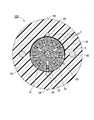
- a plurality of inclusions 3a may be arranged at the center (radial center) of the optical fiber cable 100.
- the external force when an external force is applied to the optical fiber cable 100, the external force can be more reliably absorbed.
- the inclusion 3a has water absorption, it becomes possible to improve the waterproof performance in the center.
- the inclusion 3b disposed in the optical fiber unit 10 may be the same material as the inclusion 3a located between the optical fiber units 10 or may be a different material.
- Sb is defined by the sum of the cross-sectional area of the inclusion 3a and the cross-sectional area of the inclusion 3b.
- the same effect as that of the above embodiment is achieved by setting the fiber filling ratio ⁇ and the space filling ratio d including the value of Sb within the ranges shown in the above embodiment. Can be obtained.
- the optical fiber cable 100 may include the inclusion 3b and the binding material 2. Further, the optical fiber cable 100 does not have the inclusion 3 a located between the optical fiber units 10, and may have the inclusion 3 b located in the optical fiber unit 10.
Landscapes
- Physics & Mathematics (AREA)
- General Physics & Mathematics (AREA)
- Optics & Photonics (AREA)
- Communication Cables (AREA)
- Light Guides In General And Applications Therefor (AREA)
- Glass Compositions (AREA)
Priority Applications (9)
| Application Number | Priority Date | Filing Date | Title |
|---|---|---|---|
| CA3051607A CA3051607C (en) | 2017-02-20 | 2018-02-06 | Optical fiber cable |
| ES18753890T ES2937932T3 (es) | 2017-02-20 | 2018-02-06 | Cable de fibra óptica |
| SG11201906136SA SG11201906136SA (en) | 2017-02-20 | 2018-02-06 | Optical fiber cable |
| EP18753890.5A EP3584617B1 (en) | 2017-02-20 | 2018-02-06 | Optical fiber cable |
| CN201880010916.1A CN110268297B (zh) | 2017-02-20 | 2018-02-06 | 光纤缆线 |
| US16/481,768 US10884208B2 (en) | 2017-02-20 | 2018-02-06 | Optical fiber cable |
| AU2018222025A AU2018222025B2 (en) | 2017-02-20 | 2018-02-06 | Optical fiber cable |
| KR1020197022086A KR102050361B1 (ko) | 2017-02-20 | 2018-02-06 | 광섬유 케이블 |
| SA519402454A SA519402454B1 (ar) | 2017-02-20 | 2019-08-18 | كبل ألياف ضوئية |
Applications Claiming Priority (2)
| Application Number | Priority Date | Filing Date | Title |
|---|---|---|---|
| JP2017029056A JP6255120B1 (ja) | 2017-02-20 | 2017-02-20 | 光ファイバケーブル |
| JP2017-029056 | 2017-02-20 |
Publications (1)
| Publication Number | Publication Date |
|---|---|
| WO2018150947A1 true WO2018150947A1 (ja) | 2018-08-23 |
Family
ID=60860193
Family Applications (1)
| Application Number | Title | Priority Date | Filing Date |
|---|---|---|---|
| PCT/JP2018/003976 WO2018150947A1 (ja) | 2017-02-20 | 2018-02-06 | 光ファイバケーブル |
Country Status (11)
| Country | Link |
|---|---|
| US (1) | US10884208B2 (es) |
| EP (1) | EP3584617B1 (es) |
| JP (1) | JP6255120B1 (es) |
| KR (1) | KR102050361B1 (es) |
| CN (1) | CN110268297B (es) |
| AU (1) | AU2018222025B2 (es) |
| CA (1) | CA3051607C (es) |
| ES (1) | ES2937932T3 (es) |
| SA (1) | SA519402454B1 (es) |
| SG (1) | SG11201906136SA (es) |
| WO (1) | WO2018150947A1 (es) |
Cited By (3)
| Publication number | Priority date | Publication date | Assignee | Title |
|---|---|---|---|---|
| CN112400130A (zh) * | 2018-09-11 | 2021-02-23 | 株式会社藤仓 | 光纤电缆 |
| WO2021117843A1 (en) * | 2019-12-11 | 2021-06-17 | Fujikura Ltd. | Optical fiber cable |
| WO2022074816A1 (ja) * | 2020-10-09 | 2022-04-14 | 日本電信電話株式会社 | 光ケーブル |
Families Citing this family (5)
| Publication number | Priority date | Publication date | Assignee | Title |
|---|---|---|---|---|
| JP7068142B2 (ja) * | 2018-11-09 | 2022-05-16 | 株式会社フジクラ | 光ファイバケーブル |
| JP7068131B2 (ja) * | 2018-10-15 | 2022-05-16 | 株式会社フジクラ | 光ファイバケーブル |
| JP7068114B2 (ja) * | 2018-09-11 | 2022-05-16 | 株式会社フジクラ | 光ファイバケーブル |
| WO2020075734A1 (ja) * | 2018-10-11 | 2020-04-16 | 株式会社フジクラ | 光ファイバケーブル |
| WO2022092251A1 (ja) * | 2020-10-30 | 2022-05-05 | 住友電気工業株式会社 | 光ファイバケーブルおよび光ファイバユニット |
Citations (8)
| Publication number | Priority date | Publication date | Assignee | Title |
|---|---|---|---|---|
| JPH04177304A (ja) * | 1990-11-13 | 1992-06-24 | Fukuoka Cloth Kogyo Kk | 走水防止光ケーブル |
| JPH11203955A (ja) * | 1998-01-16 | 1999-07-30 | Sumitomo Electric Ind Ltd | 光複合架空地線 |
| JP2004069939A (ja) * | 2002-08-05 | 2004-03-04 | Furukawa Electric Co Ltd:The | 光ファイバケーブル |
| JP2004139068A (ja) * | 2002-09-26 | 2004-05-13 | Fujikura Ltd | 光ファイバケーブル及びその構造 |
| JP2005010651A (ja) | 2003-06-20 | 2005-01-13 | Fujikura Ltd | 光ファイバケーブル |
| JP2015215447A (ja) * | 2014-05-09 | 2015-12-03 | 株式会社フジクラ | 光ファイバケーブル |
| US20150370026A1 (en) * | 2014-06-23 | 2015-12-24 | Corning Optical Communications LLC | Optical fiber cable |
| JP2017029056A (ja) | 2015-07-31 | 2017-02-09 | 日清製粉株式会社 | 即席麺の製造方法 |
Family Cites Families (21)
| Publication number | Priority date | Publication date | Assignee | Title |
|---|---|---|---|---|
| GB2161614B (en) * | 1984-06-19 | 1987-12-16 | Telephone Cables Ltd | Optical fibre cables |
| US5671441A (en) | 1994-11-29 | 1997-09-23 | International Business Machines Corporation | Method and apparatus for automatic generation of I/O configuration descriptions |
| DE69943330D1 (de) | 1998-02-23 | 2011-05-19 | Draka Comteq Bv | Verbundbauelemente mit thermotropem flüssigkristallinem Polymer Verstärkung für faseroptische Kabel |
| JP2001194567A (ja) | 2000-01-11 | 2001-07-19 | Sumitomo Electric Ind Ltd | 光ファイバケーブル |
| US6671441B1 (en) * | 2000-08-22 | 2003-12-30 | Fitel Usa Corp. | Optical cabling apparatus having improved dry filling compound and method for making |
| US6749446B2 (en) * | 2001-10-10 | 2004-06-15 | Alcatel | Optical fiber cable with cushion members protecting optical fiber ribbon stack |
| JP2004184546A (ja) | 2002-11-29 | 2004-07-02 | Fujikura Ltd | 光ケーブル |
| US7421169B2 (en) | 2003-06-20 | 2008-09-02 | Fujikura Ltd. | Optical fiber cable |
| JP2005068617A (ja) | 2003-08-28 | 2005-03-17 | Toray Monofilament Co Ltd | ケーブル部材用ポリエステルモノフィラメント |
| JP4728132B2 (ja) | 2006-02-01 | 2011-07-20 | 日本電信電話株式会社 | 光コード |
| KR100872229B1 (ko) * | 2006-12-06 | 2008-12-05 | 엘에스전선 주식회사 | 중심멤버 구조가 개선된 루즈튜브형 광케이블 |
| US7724998B2 (en) | 2007-06-28 | 2010-05-25 | Draka Comteq B.V. | Coupling composition for optical fiber cables |
| WO2009034667A1 (en) | 2007-09-12 | 2009-03-19 | Fujikura Ltd. | Loose tube optical fiber cable |
| CA2769324A1 (en) * | 2009-07-31 | 2011-02-03 | Corning Cable Systems Llc | Optical fiber cables |
| US8818153B2 (en) | 2010-06-22 | 2014-08-26 | Sumitomo Electric Industries, Ltd. | Opto-electro hybrid cable having electronic wires and optical fibers |
| JP5581841B2 (ja) | 2010-06-22 | 2014-09-03 | 住友電気工業株式会社 | 光電気複合ケーブル |
| US8953916B2 (en) * | 2011-06-22 | 2015-02-10 | Corning Cable Systems Llc | Multi-fiber, fiber optic cable assemblies providing constrained optical fibers within an optical fiber sub-unit, and related fiber optic components, cables, and methods |
| JP5840902B2 (ja) | 2011-09-05 | 2016-01-06 | 株式会社フジクラ | ルースチューブ型光ファイバケーブル |
| FR2998176B1 (fr) * | 2012-11-16 | 2015-01-16 | Univ Blaise Pascal Clermont Ii | Composition de polysaccharide sulfate |
| JP6015542B2 (ja) | 2013-04-25 | 2016-10-26 | 日立金属株式会社 | 光電気複合ケーブル |
| JP6586925B2 (ja) * | 2016-06-13 | 2019-10-09 | 住友電気工業株式会社 | 光ファイバケーブル |
-
2017
- 2017-02-20 JP JP2017029056A patent/JP6255120B1/ja active Active
-
2018
- 2018-02-06 ES ES18753890T patent/ES2937932T3/es active Active
- 2018-02-06 AU AU2018222025A patent/AU2018222025B2/en active Active
- 2018-02-06 CN CN201880010916.1A patent/CN110268297B/zh active Active
- 2018-02-06 EP EP18753890.5A patent/EP3584617B1/en active Active
- 2018-02-06 CA CA3051607A patent/CA3051607C/en active Active
- 2018-02-06 SG SG11201906136SA patent/SG11201906136SA/en unknown
- 2018-02-06 WO PCT/JP2018/003976 patent/WO2018150947A1/ja active Application Filing
- 2018-02-06 US US16/481,768 patent/US10884208B2/en active Active
- 2018-02-06 KR KR1020197022086A patent/KR102050361B1/ko active IP Right Grant
-
2019
- 2019-08-18 SA SA519402454A patent/SA519402454B1/ar unknown
Patent Citations (8)
| Publication number | Priority date | Publication date | Assignee | Title |
|---|---|---|---|---|
| JPH04177304A (ja) * | 1990-11-13 | 1992-06-24 | Fukuoka Cloth Kogyo Kk | 走水防止光ケーブル |
| JPH11203955A (ja) * | 1998-01-16 | 1999-07-30 | Sumitomo Electric Ind Ltd | 光複合架空地線 |
| JP2004069939A (ja) * | 2002-08-05 | 2004-03-04 | Furukawa Electric Co Ltd:The | 光ファイバケーブル |
| JP2004139068A (ja) * | 2002-09-26 | 2004-05-13 | Fujikura Ltd | 光ファイバケーブル及びその構造 |
| JP2005010651A (ja) | 2003-06-20 | 2005-01-13 | Fujikura Ltd | 光ファイバケーブル |
| JP2015215447A (ja) * | 2014-05-09 | 2015-12-03 | 株式会社フジクラ | 光ファイバケーブル |
| US20150370026A1 (en) * | 2014-06-23 | 2015-12-24 | Corning Optical Communications LLC | Optical fiber cable |
| JP2017029056A (ja) | 2015-07-31 | 2017-02-09 | 日清製粉株式会社 | 即席麺の製造方法 |
Non-Patent Citations (1)
| Title |
|---|
| See also references of EP3584617A4 |
Cited By (9)
| Publication number | Priority date | Publication date | Assignee | Title |
|---|---|---|---|---|
| CN112400130A (zh) * | 2018-09-11 | 2021-02-23 | 株式会社藤仓 | 光纤电缆 |
| US11592634B2 (en) | 2018-09-11 | 2023-02-28 | Fujikura Ltd. | Optical fiber cable |
| CN112400130B (zh) * | 2018-09-11 | 2023-04-11 | 株式会社藤仓 | 光纤电缆 |
| WO2021117843A1 (en) * | 2019-12-11 | 2021-06-17 | Fujikura Ltd. | Optical fiber cable |
| TWI759001B (zh) * | 2019-12-11 | 2022-03-21 | 日商藤倉股份有限公司 | 光纖電纜 |
| JP2022544424A (ja) * | 2019-12-11 | 2022-10-18 | 株式会社フジクラ | 光ファイバケーブル |
| JP7307859B2 (ja) | 2019-12-11 | 2023-07-12 | 株式会社フジクラ | 光ファイバケーブル |
| US11782228B2 (en) | 2019-12-11 | 2023-10-10 | Fujikura Ltd. | Optical fiber cable |
| WO2022074816A1 (ja) * | 2020-10-09 | 2022-04-14 | 日本電信電話株式会社 | 光ケーブル |
Also Published As
| Publication number | Publication date |
|---|---|
| EP3584617A1 (en) | 2019-12-25 |
| CA3051607A1 (en) | 2018-08-23 |
| JP2018136376A (ja) | 2018-08-30 |
| KR20190095485A (ko) | 2019-08-14 |
| CN110268297A (zh) | 2019-09-20 |
| EP3584617B1 (en) | 2023-01-11 |
| JP6255120B1 (ja) | 2017-12-27 |
| CN110268297B (zh) | 2020-02-21 |
| EP3584617A4 (en) | 2020-12-02 |
| CA3051607C (en) | 2020-06-30 |
| ES2937932T3 (es) | 2023-04-03 |
| SA519402454B1 (ar) | 2022-06-06 |
| AU2018222025B2 (en) | 2020-01-16 |
| KR102050361B1 (ko) | 2019-11-29 |
| SG11201906136SA (en) | 2019-08-27 |
| AU2018222025A1 (en) | 2019-09-05 |
| US20190391353A1 (en) | 2019-12-26 |
| US10884208B2 (en) | 2021-01-05 |
Similar Documents
| Publication | Publication Date | Title |
|---|---|---|
| WO2018150947A1 (ja) | 光ファイバケーブル | |
| WO2013049484A1 (en) | Fiber optic ribbon cable having enhanced ribbon stack coupling and methods thereof | |
| AU2022202391B2 (en) | Optical fiber cable | |
| AU2018277435A1 (en) | Optical fiber cable and method of manufacturing optical fiber cable | |
| JP2022100376A (ja) | 光ファイバケーブル | |
| JP7184526B2 (ja) | 光ファイバケーブル | |
| JP6719175B2 (ja) | 光ファイバケーブル | |
| JP7068114B2 (ja) | 光ファイバケーブル | |
| JP2020091452A (ja) | 光ファイバケーブル | |
| JP7068131B2 (ja) | 光ファイバケーブル | |
| JP2022101280A (ja) | 光ファイバケーブル | |
| EP4288818A1 (en) | Annealed subunits in bundled drop assembly and process of annealing subunits in bundled drop assembly | |
| CA3220819A1 (en) | Optical fiber cable and method of manufacturing optical fiber cable | |
| JP2005010651A (ja) | 光ファイバケーブル |
Legal Events
| Date | Code | Title | Description |
|---|---|---|---|
| 121 | Ep: the epo has been informed by wipo that ep was designated in this application |
Ref document number: 18753890 Country of ref document: EP Kind code of ref document: A1 |
|
| ENP | Entry into the national phase |
Ref document number: 3051607 Country of ref document: CA |
|
| ENP | Entry into the national phase |
Ref document number: 20197022086 Country of ref document: KR Kind code of ref document: A |
|
| NENP | Non-entry into the national phase |
Ref country code: DE |
|
| ENP | Entry into the national phase |
Ref document number: 2018222025 Country of ref document: AU Date of ref document: 20180206 Kind code of ref document: A |
|
| WWE | Wipo information: entry into national phase |
Ref document number: 2018753890 Country of ref document: EP |