WO2018150892A1 - キャップ - Google Patents
キャップ Download PDFInfo
- Publication number
- WO2018150892A1 WO2018150892A1 PCT/JP2018/003420 JP2018003420W WO2018150892A1 WO 2018150892 A1 WO2018150892 A1 WO 2018150892A1 JP 2018003420 W JP2018003420 W JP 2018003420W WO 2018150892 A1 WO2018150892 A1 WO 2018150892A1
- Authority
- WO
- WIPO (PCT)
- Prior art keywords
- nozzle
- cap
- opening hole
- contents
- dispensing opening
- Prior art date
- Legal status (The legal status is an assumption and is not a legal conclusion. Google has not performed a legal analysis and makes no representation as to the accuracy of the status listed.)
- Ceased
Links
Images



Classifications
-
- B—PERFORMING OPERATIONS; TRANSPORTING
- B65—CONVEYING; PACKING; STORING; HANDLING THIN OR FILAMENTARY MATERIAL
- B65D—CONTAINERS FOR STORAGE OR TRANSPORT OF ARTICLES OR MATERIALS, e.g. BAGS, BARRELS, BOTTLES, BOXES, CANS, CARTONS, CRATES, DRUMS, JARS, TANKS, HOPPERS, FORWARDING CONTAINERS; ACCESSORIES, CLOSURES, OR FITTINGS THEREFOR; PACKAGING ELEMENTS; PACKAGES
- B65D47/00—Closures with filling and discharging, or with discharging, devices
- B65D47/04—Closures with discharging devices other than pumps
- B65D47/06—Closures with discharging devices other than pumps with pouring spouts or tubes; with discharge nozzles or passages
Definitions
- the present invention relates to a cap.
- This application claims priority based on Japanese Patent Application No. 2017-026852 filed in Japan on February 16, 2017, the contents of which are incorporated herein by reference.
- a nozzle cap (cap) attached to a container that stores liquid contents such as softeners and liquid detergents is used to pour out contents from a tilted container body.
- a container that stores liquid contents such as softeners and liquid detergents is used to pour out contents from a tilted container body.
- the contents liquid is appropriately added from a refilling pouch for a long period of time.
- One aspect of the present invention is made in view of the above-mentioned problems of the prior art, and suppresses the flow loss due to the viscous friction of the contents with respect to the inner wall surface of the nozzle cap, thereby improving the pouring property of the contents.
- An object of the present invention is to provide a cap that can be used.
- a cap that is detachably attached to the mouth of a container body that contains a viscous liquid that has a viscosity exceeding 500 mPa ⁇ s when used, and tilts and dispenses the content.
- a fitting portion that fits into the mouth portion, a nozzle base that is coaxially provided inside the fitting portion and has a dispensing opening hole in a bottom surface portion, and the dispensing opening hole.
- An outflow restricting portion is provided on at least a part of the periphery surrounded by the portion.
- the outflow restricting portion may be provided on the entire periphery surrounded by the nozzle portion in the dispensing opening hole.
- the outflow restricting portion may be provided in other peripheral portions excluding the peripheral portion that is at the lower side when tilted in the dispensing opening hole.
- the outflow restricting portion may be provided in a half region of the peripheral edge surrounded by the nozzle portion in the dispensing opening hole.
- the outflow restricting portion may be provided so as to gradually reduce the pouring opening hole in a direction that becomes an upper side of the pouring opening hole when tilted. Good.
- the nozzle portion may have a U-shape that opens to one end side in the radial direction intersecting the axial direction.
- the present invention it is possible to provide a cap capable of suppressing the flow loss due to the viscous friction of the contents with respect to the inner wall surface of the nozzle portion and improving the pouring property of the contents.
- the side view which shows the structure of the container of the erect state in which the nozzle cap (cap) which concerns on 1st Embodiment was mounted
- the side view which shows the structure of the nozzle cap of 1st Embodiment.
- the cross-sectional perspective view which shows the structure of the nozzle cap of 1st Embodiment.
- the perspective view which shows a mode that the nozzle cap of 1st Embodiment was seen from the bottom part side.
- the perspective view which shows a mode that the nozzle cap of 1st Embodiment was seen from the nozzle part side.
- the fragmentary sectional view which shows the structure of the nozzle part of the nozzle cap of 1st Embodiment.
- the top view which looked at the nozzle cap of the conventional structure from the axial direction. The figure which shows the mode at the time of using the container provided with the nozzle cap.
- the inventor of the present application pays attention to the time from when the contents flow out of the container body until it comes into contact with the inner wall surface of the nozzle cap. The shape was examined.
- some configurations of the embodiment according to the cap of the present invention will be described.
- FIG. 1 is a side view showing a configuration of an upright container 100 in which a nozzle cap (cap) 10 according to the present embodiment is attached to a mouth portion 101 of a container body 100A.
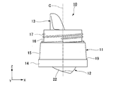
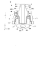
- FIG. 2 is a side view showing the configuration of the nozzle cap 10.
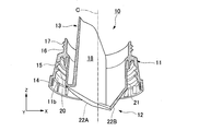
- FIG. 3 is a cross-sectional perspective view showing the configuration of the nozzle cap 10.
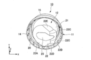
- FIG. 4 is a perspective view showing the nozzle cap 10 as seen from the bottom side.
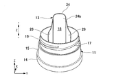
- FIG. 5 is a perspective view showing a state in which the nozzle cap 10 is viewed from the nozzle portion 13 side.
- FIG. 6 is a partial cross-sectional view showing the configuration of the nozzle portion 13 of the nozzle cap 10.
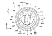
- FIG. 7 is a top view of the nozzle cap 10 as viewed from the axial direction.
- the nozzle cap 10 of the present embodiment is an inner plug that fits into a mouth portion 101 formed at the upper end of a container main body 100 ⁇ / b> A that accommodates contents, and the contents are measured outside thereof.
- a measuring cap 102 is attached.
- the container body 100A is integrally formed by, for example, blow molding using an olefin synthetic resin such as polyethylene.
- the container main body 100A contains, for example, liquid substances such as liquid detergents, liquid bleaches, liquid softeners, and solvents, and granular substances such as granular detergents, granular bleaches, and granular seasonings as contents.
- a space 100a is provided.
- the mouth portion 101 of the container main body 100A is formed in a cylindrical shape centering on an axis C extending in the vertical direction (Z direction), and opens the accommodation space 100a upward.
- a male screw portion (not shown) is formed around the axis C on the outer periphery of the mouth portion 101, and the nozzle cap 10 in this embodiment is screwed together.
- the configuration of the screw type nozzle cap 10 will be described, but the present invention is not limited thereto.
- it may be configured to be inserted and fitted into the mouth portion 101 of the container main body 100 ⁇ / b> A so as not to be pulled upward by engagement of press-fitting or an undercut portion.
- a direction along the axis C is appropriately referred to as an axial direction
- a direction perpendicular to the axis C is referred to as a radial direction
- a direction around the axis about the axis C is appropriately referred to as a circumferential direction.
- the measuring cap 102 side in the axial direction is appropriately referred to as the upper side (upper side)
- the container body 100 ⁇ / b> A side is appropriately referred to as the lower side (lower side).
- the axial direction is referred to as the Z direction
- the radial direction in FIG. 1 is defined as the X direction
- the Z direction and the direction orthogonal to the X direction (the direction orthogonal to the paper surface in FIG. 1) are appropriately described as the Y direction.
- the nozzle cap 10 is formed by injection molding using an olefin-based synthetic resin such as polypropylene, for example.
- the nozzle cap 10 mainly has a fitting part 11, a nozzle base part 12, and a nozzle part 13, and is configured around an axis C.
- the fitting part 11 has a cylindrical shape and is fitted to the outside of the mouth part 101 of the container main body 100A shown in FIG.
- the fitting portion 11 is an intermediate portion that is continuous with the upper end of the annular convex portion 14 along the axis C on the lower end side of the nozzle cap 10 and located radially inward of the annular convex portion 14. It has a portion 15 and an upper portion 16 that is continuous with the end of the intermediate portion 15 opposite to the annular convex portion 14 and that is located radially inward of the intermediate portion 15.
- a male screw portion 17 that is screwed into the female screw portion of the measuring cap 102 is formed.
- the nozzle cap 10 of the present embodiment has a shape in which the diameter is gradually increased outward in the radial direction from the upper portion 16 toward the intermediate portion 15 and the annular convex portion 14 along the axis C.
- the nozzle cap 10 is equipped with the above-described measuring cap 102.
- the measuring cap 102 is attached from the outside of the upper portion 16 so as to be within a step 19 between the upper portion 16 and the intermediate portion 15.
- the measuring cap 102 is configured to have a continuous outer shape from the measuring cap 102 to the nozzle cap 10 in a state where the measuring cap 102 is attached to the nozzle cap 10.
- fitting portion 11 is formed with a female screw portion 20 around the axis C along the inner peripheral surface 11b, and a male screw portion (outside the mouth portion 101 of the container main body 100A shown in FIG. (Not shown).
- the nozzle base portion 12 is provided coaxially inside the fitting portion 11, and is inserted into the mouth portion 101 of the container main body 100A when the cap is attached.
- the nozzle base portion 12 has a bottomed cylindrical shape having an inner cylinder portion 21 and a bottom surface portion 22 provided on the lower end side of the inner cylinder portion 21.
- a dispensing opening 23 (FIG. 4) is formed.
- the inner cylinder portion 21 is located radially inward (on the axis C side) from the upper portion 16 of the fitting portion 11, and the lower end side along the axis C is outside the annular convex portion 14 (container main body). 100A).
- the bottom surface portion 22 has a convex V-shape on the container body 100A side, and as shown in FIG. 4, the first inclined surface 22A and the second inclined surface 22B having different inclination angles from each other.
- the first inclined surface 22A and the second inclined surface 22B have a third inclined surface 22D and a fourth inclined surface 22E facing each other on an extension line of the connecting top portions 22C and 22C, and toward the lowermost connecting top portions 22C and 22C. It gradually becomes thinner.
- An extraction opening hole 23 is formed from the first inclined surface 22A to the second inclined surface 22B of the bottom surface portion 22 as described above.
- the nozzle portion 13 is erected on the bottom surface portion 22 of the nozzle base portion 12, and extends toward the opposite side of the container main body 100A along the axis C. Specifically, the nozzle portion 13 includes a flange-like portion 24 and a pair of receiving portions 26 and 26 erected on the first inclined surface 22A of the bottom surface portion 22.
- the bowl-shaped portion 24 extends so as to rise upward (+ Z direction) from the periphery of the dispensing opening hole 23, and the flow path diameter of the nozzle flow path 18 formed on the inner side is the extending direction (Z direction). It is almost constant. As shown in FIG. 7, the bowl-shaped portion 24 is provided so as to surround a part of the peripheral edge of the dispensing opening hole 23 when viewed from the axial direction. As shown in FIG. 7, the bowl-shaped portion 24 has a U-shaped cross section that opens to the + X side, and the opening ends 24 a and 24 a on the + X side do not follow the peripheral edge of the dispensing opening hole 23. Extends along the direction.
- the extraction opening 23 of the present embodiment has a bowl shape as an example.
- the bowl-shaped portion 24 surrounds a part of the first opening 23A1 formed in the first inclined surface 22A in the dispensing opening hole 23, and is provided along an arc-shaped peripheral edge.
- the second opening 23B1 formed in the second inclined surface 22B in the dispensing opening hole 23 protrudes radially outward from the opening end 24a on the + X side of the bowl-shaped part 24, and the bowl-shaped part It is open without being surrounded by 24.
- the dispensing opening hole 23 is formed from the first inclined surface 22A of the bottom surface portion 22 to the second inclined surface 22B. Since the second inclined surface 22B, which is the upper side when tilting, is inclined so as to be folded back with respect to the first inclined surface 22A on which the nozzle portion 13 is erected, the contents are second inclined surface 22B when being poured out. It is difficult to get on the side. Therefore, it is easy to maintain the opening state of the part formed in the 2nd inclined surface 22B among the opening holes 23 for extraction, and one part can be functioned as the air replacement hole 25.
- an outflow restricting portion 29 made of a part of the first inclined surface 22A of the bottom surface portion 22 is provided inside the bowl-shaped portion 24, an outflow restricting portion 29 made of a part of the first inclined surface 22A of the bottom surface portion 22 is provided.
- the outflow restricting portion 29 is provided on each opening end 24a, 24a side of the bowl-shaped portion 24, respectively. Due to these outflow restricting portions 29, a part of the periphery of the dispensing opening hole 23 is separated from the inner wall surface 24 b of the bowl-shaped portion 24.
- the outflow restricting portions 29, 29 expand toward each other as they go to the + X side of the extraction opening hole 23, and of the peripheral edge 23a of the extraction opening hole 23, a peripheral edge portion 23b that is inclined linearly with respect to the X direction. , 23b.
- the dispensing opening hole 23 has a bowl shape, and a part on the + X side, which is higher when tilted, is smaller than the lower side by the outflow regulating portion 29 described above. As shown in FIG. 7, a part of the dispensing opening hole 23 protrudes radially outward (+ X side) from the opening end 24 a of the bowl-shaped part 24, and is opened without being surrounded by the bowl-shaped part 24. Has been.
- a pair of receiving parts 26 that extend in the axial direction along the hook-shaped part 24 and bend following the outer shape of the hook-shaped part 24. , 26 are provided.
- the pair of receiving portions 26, 26 are exposed to the outside of the fitting portion 11 with respect to the first portion 26 ⁇ / b> A that is hidden inside the fitting portion 11 when viewed from the side.
- the two portions 26 ⁇ / b> B have a tapered shape that becomes extremely narrow toward the tip (+ Z side) of the bowl-shaped portion 24.
- the pair of receiving portions 26 and 26 are curved so as to spread outward in the radial direction from the top portion q on the ⁇ X side of the nozzle portion 13 toward the + X side when viewed from the axial direction.
- the nozzle portion 13 is provided apart from the nozzle portion 13.
- the + X side opening end 26 a of the first portion 26 A of the receiving portion 26 is located on the ⁇ X side with respect to the opening end 24 a of the bowl-shaped portion 24.
- the nozzle cap 10 of the present embodiment described above has the female screw portion 20 of the fitting portion 11 while inserting the bottom side of the nozzle base portion 12 into the accommodating space 100a from the mouth portion 101 of the container main body 100A shown in FIG. Is attached to the container main body 100A by being fastened while being screwed to a male screw portion (not shown) on the container main body 100A side.
- the measuring cap 102 is attached to the nozzle cap 10 attached to the container main body 100 ⁇ / b> A by screwing and fastening the female screw portion (not shown) of the measuring cap 102 to the male screw portion 17 of the fitting portion 11. .
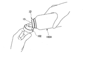
- the measuring cap 102 When the contents are poured out from the container main body 100A, the measuring cap 102 is rotated in the direction opposite to that at the time of fastening, and the female screw portion (not shown) of the measuring cap 102 and the male screw portion 17 of the nozzle cap 10 And the measuring cap 102 is removed from the nozzle cap 10. With the measuring cap 102 removed, the container body 100A is gripped so that the opening side of the nozzle portion 13 of the nozzle cap 10 faces upward, and then the nozzle portion 13 is positioned downward as shown in FIG. By tilting obliquely, the contents stored in the container body 100A can be poured out from the nozzle portion 13 to the measuring cap 102 and weighed.
- the content liquid leaking outside the bowl-like portion 24 without entering the dispensing opening 23 is It is received by a pair of receiving portions 26, 26 existing on both sides.
- the content liquid received by each receiving portion 26 is guided to the tip side along the second portion 26B at the time of tilting, and is poured out during the subsequent measurement.
- the measuring cap 102 When refilling the container body 100 ⁇ / b> A with contents, the measuring cap 102 is rotated in the opposite direction to that at the time of fastening, so that the female screw portion (not shown) of the measuring cap 102 and the male screw portion 17 of the nozzle cap 10 are screwed together. And the measuring cap 102 is removed from the nozzle cap 10. With the measuring cap 102 removed, the contents are refilled from the refill container into the container body 100A through the nozzle portion 13 of the nozzle cap 10.
- the outflow restricting portion 29 as in the present invention is not provided in the dispensing opening hole 23, and the nozzle portion is formed along the periphery of the dispensing opening hole 202. 13 was erected, and substantially the entire inner wall surface 24 b of the bowl-shaped portion 24 coincided with the peripheral edge of the dispensing opening hole 202. Therefore, the content flows along the inner wall surface 24b of the bowl-shaped portion 24 immediately after passing through the dispensing opening hole 202, and when the content flows through the nozzle flow path 18 as the viscosity becomes higher.
- the central portion not in contact with the inner wall surface 24b is not affected by viscous friction with respect to the inner wall surface 24b, and therefore the flow velocity is higher than the peripheral portion in contact with the inner wall surface 24b. Is fast. That is, the velocity distribution of the contents flowing in the bowl-shaped portion 24 is the slowest on the inner wall surface 24 b side, gradually increases with distance from the inner wall surface 24 b, and is highest in the central portion of the nozzle channel 18. That is, the greater the amount that does not contact the inner wall surface 24b of the bowl-shaped portion 24, the more the influence of viscous friction can be reduced, and the flow speed of the contents can be increased.
- a pair of outflow restricting portions 29 is provided in a part of the region surrounded by the flange-shaped portion 24 of the nozzle portion 13 in the dispensing opening hole 23 in the nozzle cap 10. At least a part of the opening 23 for use was configured to be away from the inner wall surface 24 b of the bowl-shaped portion 24. Contents such as liquid detergent have a high viscosity, and when the viscosity of the contents in use exceeds 500 mPa ⁇ s, the reverberation of the shape of the dispensing opening 23 immediately after passing through the dispensing opening 23 is obtained. It flows out with the state left.
- the outflow restricting portion 29 has a configuration in which the periphery of the pouring opening hole 23 is kept away from the inner wall surface 24b of the bowl-shaped portion 24, so that among the contents that have passed through the pouring opening hole 23 during use
- the content that has passed between the pair of outflow restricting portions 29 flows out immediately after that without contacting the inner wall surface 24b of the bowl-shaped portion 24, and the time until the contents contact the inner wall surface 24b of the bowl-shaped portion 24 Can earn.
- the contents flowing on the open side of the bowl-shaped portion 24 are not easily affected by viscous friction against the inner wall surface 24b.
- the timing at which the content flowing on the open side of the bowl-shaped portion 24 contacts the inner wall surface 24b of the bowl-shaped portion 24 is delayed as much as possible. It is possible to increase the flow speed of the entire flowing contents. Thereby, the content extraction efficiency can be improved.
- a part of the dispensing opening hole 23 is configured to function as the air replacement hole 25, but is not limited thereto.
- the air replacement hole 25 may be provided separately from the dispensing opening hole 23.
- Air replacement can be performed smoothly in the air replacement hole 25, and the contents can be efficiently discharged from the opening hole 23 for extraction.
- the configuration of the nozzle cap 27 according to the second embodiment of the present invention will be described.
- the basic configuration of the nozzle cap 27 of the present embodiment shown below is substantially the same as that of the first embodiment, but the first outflow restricting portion 29A of the present embodiment is a bowl-shaped portion 24 of the dispensing opening hole 23B. It differs in that it is provided on the entire periphery surrounded by. Therefore, in the following description, a different point from the said embodiment is demonstrated in detail, and description of a common location is abbreviate
- the same reference numerals are given to the same components as those in FIGS.
- FIG. 8 is a top view of the nozzle cap 27 according to the second embodiment viewed from the axial direction.
- the nozzle cap 27 mainly discharges contents from the first opening 28 surrounded by the hook-like portion 24 in the dispensing opening hole 23 ⁇ / b> B provided inside the hook-like portion 24.
- the portion located radially outward (+ X side) from the opening ends 24 a and 24 a of the bowl-shaped portion 24 mainly functions as the air replacement hole 25.
- the opening width of the air replacement hole 25 is gradually reduced by the second outflow restricting portion 29B provided on both sides in the Y direction toward the upper side when tilting, than the opening hole 23B for pouring.
- the nozzle cap 27 of the present embodiment has a configuration in which the first outflow restricting portion 29A is provided along the entire periphery of the dispensing opening hole 23B surrounded by the bowl-shaped portion 24. That is, the first outflow restricting portion 29 ⁇ / b> A is formed over the entire inner wall surface 24 b of the bowl-shaped portion 24.
- the first outflow restricting portion 29A exists between the inner wall surface 24b of the bowl-shaped portion 24 and the first opening 28, and the periphery of the first opening 28 is separated from the inner wall surface 24b of the bowl-shaped portion 24.
- the first outflow restricting portion 29A is provided with a substantially uniform width W along the periphery of the first opening 28 of the dispensing opening hole 23B.
- the width W of the first outflow restricting portion 29A is appropriately set according to the viscosity of the contents. Note that the width W of the first outflow restricting portion 29A may not be constant over the periphery of the first opening 28, and the width dimension may partially change.
- the first opening 28 of the pouring opening hole 23B has the hook-shaped portion 24. It becomes a structure away from the inner wall surface 24b, and it can earn time until it contacts the inner wall surface 24b of the bowl-shaped part 24 after the content is poured out from the opening hole 23B for pouring than the structure of 1st Embodiment. .
- the first outflow restricting portion 29A further delays the timing at which substantially the entire contents that have passed through the dispensing opening hole 23 come into contact with the inner wall surface 24b of the bowl-shaped portion 24. Can do. As a result, the flow speed of the content flowing in the nozzle flow path 18 is further increased, and the content extraction efficiency can be increased.
- the basic configuration of the nozzle cap 30 of the present embodiment shown below is substantially the same as that of the second embodiment, but a pair of outflow restricting portions 29C are formed in the dispensing opening hole 23C surrounded by the bowl-shaped portion 24. It is different in that it is formed on both sides in the Y direction of the dispensing opening hole 23C except for the region that is on the lower side when tilting. Therefore, in the following description, a different point from the said embodiment is demonstrated in detail, and description of a common location is abbreviate
- FIG. 9 is a top view of the nozzle cap 30 according to the third embodiment viewed from the axial direction.
- the nozzle cap 30 of the present embodiment is a peripheral portion on the top portion q side of the bowl-shaped portion 24 among the circumferential edges of the dispensing opening hole 23 ⁇ / b> C surrounded by the bowl-shaped portion 24 of the nozzle section 13.
- a pair of outflow restricting portions 29C and 29C are provided along the other peripheral portions 23d and 23d except 23c.
- a peripheral edge portion 23c of the dispensing opening hole 23C coincides with the inner wall surface 24b of the bowl-shaped portion 24.
- the nozzle cap 30 of the present embodiment has a configuration in which the outflow restricting portion 29C is provided except for the peripheral portion 23c on the top q side of the bowl-shaped portion 24 in the peripheral edge of the dispensing opening hole 23C.
- the contents that have passed between the peripheral portions 23d and 23d of the dispensing opening hole 23, that is, between the outflow restricting portions 29C and 29C, are prevented from spreading near the inlet of the nozzle channel 18 by the respective outflow restricting portions 29C.
- the timing of contact with the inner wall surface 24b of the bowl-shaped portion 24 can be delayed.
- the configuration of the present embodiment it is possible to improve the outflow of the contents flowing down according to gravity by suppressing an increase in the angle at which the container main body 100A is inclined during use.
- the flow rate of the entire contents can be increased by reducing the influence of the viscous friction of the contents on the inner wall surface 24b and suppressing the flow loss.
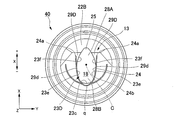
- FIG. 10 is a top view of the nozzle cap 40 according to the fourth embodiment as viewed from the axial direction.
- a pair of outflow restricting portions 29D and 29D are formed on the other peripheral portions 23f and 23f excluding the peripheral portions 23e and 23e.
- the outflow restricting portion 29D is an area that is about a half of the portion of the dispensing opening hole 23D that is surrounded by the bowl-shaped portion 24, here, the peripheral portion 23f of the upper half (+ X side) on the paper surface of FIG. , 23f only. Specifically, the outflow restricting portion 29D is formed over a predetermined region from each open end 24a of the bowl-shaped portion 24. The formation region of the outflow restricting portion 29D is appropriately set according to the type of contents. In the present embodiment, the end 29d of the outflow restricting portion 29D is located on the ⁇ X side with respect to the axis C, but may be located on the + X side.
- the outflow regulating portions 29D and 29D expand in a direction approaching each other toward the + X side of the dispensing opening hole 23D, and constitute peripheral portions 23f and 23f curved in the X direction.
- the dispensing opening hole 23D includes three opening regions (the air replacement hole 25, the first opening 28A, and the second opening 28B), and is arranged in the X direction in ascending order of the opening area from the upper side when tilted ( Opening area of air replacement hole 25 ⁇ opening area of first opening 28A ⁇ opening area of second opening 28B).
- the air replacement hole 25 is an opening in a region formed in the second inclined surface 22B of the bottom surface portion 22 in the dispensing opening hole 23D.
- 28 A of 1st opening is formed in the 1st inclined surface 22A of the bottom face part 22 among the opening holes 23D for extraction, and is an opening of the area
- the second opening 28B is an opening in a region excluding the region between the pair of outflow restricting portions 29D and 29D, which is formed in the first inclined surface 22A of the bottom surface portion 22 in the dispensing opening hole 23D.
- the opening area of the second opening 28B which is the lowest position when tilting, is widened, a large amount of contents flowing out by its own weight can be discharged. Further, the contents flowing out from the first opening 28A between the outflow restricting portions 29D and 29D in the nozzle flow path 18 by the outflow restricting portions 29D and 29D, that is, the contents flowing on the open side of the bowl-shaped portion 24. Can be delayed in contact with the inner wall surface 24b. Thereby, the influence of the viscous friction with respect to the inner wall surface 24b can be suppressed, the flow-down speed of the content flowing through the nozzle flow path 18 can be increased, and the pouring property of the content can be improved.
- the shape of the dispensing opening hole, the range, shape, size, etc. for providing the outflow restricting portion are not limited to the shapes of the above-described embodiments, and can be changed as appropriate according to the type of contents. It is.
- the present invention can be applied to a cap.
Landscapes
- Engineering & Computer Science (AREA)
- Mechanical Engineering (AREA)
- Closures For Containers (AREA)
Abstract
本発明は、ノズル部の内壁面に対する内容物の粘性摩擦による流動損失を抑えて、内容物の注出性を改善することのできるキャップを提供することを目的とする。本発明のキャップは、粘性を有する液状の内容物を収容する容器本体の口部に着脱可能に装着され内容物を傾倒注出するキャップであって、口部に嵌合する嵌合部と、嵌合部の内側に同軸をなして設けられ底面部に注出用開口孔を有するノズル基部と、注出用開口孔の少なくとも一部を囲むように底面部に立設され容器本体とは反対側に延出するノズル部と、を備え、ノズル部の内側には、注出用開口孔のうちノズル部によって囲まれた周縁の少なくとも一部に流出規制部が設けられている。
Description
本発明は、キャップに関する。
本願は、2017年2月16日に、日本に出願された特願2017-026852号に基づき優先権を主張し、その内容をここに援用する。
本願は、2017年2月16日に、日本に出願された特願2017-026852号に基づき優先権を主張し、その内容をここに援用する。
例えば、柔軟剤、液体洗剤等の液状の内容物を収容する容器に装着されるノズルキャップ(キャップ)は、傾倒させた容器本体から内容物を注出するもので、注出した内容物を計量する計量キャップとともに使用される(例えば、特許文献1)。このような容器では、収容した内容物が消費されたり、残量が少なくなったりしたときに、例えば、詰め替え用のパウチから内容液が適宜注ぎ足されることで長期的に使用される。
しかしながら、従来の構造では、容器本体から内容物を注出する際、ノズルキャップの内壁面に沿って内容物が流動することになる。液体洗剤等の高粘度の内容物がノズルキャップ内を流れる場合、ノズル部の内壁面に対する内容物の粘性摩擦によって流動損失が生じ、内容物の流下速度が低下してしまい、内容物の粘度が500mPa・sを超えるとその傾向は顕著となる。そのため、ノズルキャップを介して内容物がなかなか注出されないという不具合が生じることがあった。
本発明の一つの態様は、上記従来技術の問題点に鑑み成されたものであって、ノズルキャップの内壁面に対する内容物の粘性摩擦による流動損失を抑えて、内容物の注出性を改善することのできるキャップを提供することを目的とする。
本発明のキャップの一形態においては、粘性を有する液状でその使用時に粘度が500mPa・sを越える内容物を収容する容器本体の口部に着脱可能に装着され前記内容物を傾倒注出するキャップであって、前記口部に嵌合する嵌合部と、前記嵌合部の内側に同軸をなして設けられ底面部に注出用開口孔を有するノズル基部と、前記注出用開口孔の少なくとも一部を囲むように前記底面部に立設され前記容器本体とは反対側に延出するノズル部と、を備え、前記ノズル部の内側には、前記注出用開口孔のうち前記ノズル部によって囲まれた周縁の少なくとも一部に流出規制部が設けられている。
本発明のキャップの一形態において、前記流出規制部は、前記注出用開口孔のうち前記ノズル部によって囲まれた周縁全体に設けられている構成としてもよい。
本発明のキャップの一形態において、前記流出規制部は、前記注出用開口孔のうち少なくとも傾倒時に下側になる周縁部分を除く他の周縁部分に設けられている構成としてもよい。
本発明のキャップの一形態において、前記流出規制部は、前記注出用開口孔のうち前記ノズル部によって囲まれた周縁の1/2の領域に設けられている構成としてもよい。
本発明のキャップの一形態において、前記流出規制部は、前記注出用開口孔のうち傾倒時に上側となる方向へ前記注出用開口孔を漸次縮寸するように設けられている構成としてもよい。
本発明のキャップの一形態において、前記ノズル部は、軸方向に交差する径方向の一端側に開口するU字形状をなす構成としてもよい。
本発明によれば、ノズル部の内壁面に対する内容物の粘性摩擦による流動損失を抑えて、内容物の注出性を改善することのできるキャップを提供することができる。
本願発明者は、内容物の注出性を改善するために、容器本体から内容物が流出してからノズルキャップの内壁面に接するまでの時間に着目し、ノズルキャップにおける注出用開口孔の形状を検討した。
以下、本発明のキャップに係る実施形態の構成についていくつか説明する。
以下、本発明のキャップに係る実施形態の構成についていくつか説明する。
[第1実施形態]
図1は、本実施形態に係るノズルキャップ(キャップ)10が容器本体100Aの口部101に装着された正立状態の容器100の構成を示す側面図である。図2は、ノズルキャップ10の構成を示す側面図である。図3は、ノズルキャップ10の構成を示す断面斜視図である。図4は、ノズルキャップ10を底部側から見た様子を示す斜視図である。図5は、ノズルキャップ10をノズル部13側から見た様子を示す斜視図である。図6は、ノズルキャップ10のノズル部13の構成を示す部分断面図である。図7は、ノズルキャップ10を軸線方向から見た上面図である。
図1は、本実施形態に係るノズルキャップ(キャップ)10が容器本体100Aの口部101に装着された正立状態の容器100の構成を示す側面図である。図2は、ノズルキャップ10の構成を示す側面図である。図3は、ノズルキャップ10の構成を示す断面斜視図である。図4は、ノズルキャップ10を底部側から見た様子を示す斜視図である。図5は、ノズルキャップ10をノズル部13側から見た様子を示す斜視図である。図6は、ノズルキャップ10のノズル部13の構成を示す部分断面図である。図7は、ノズルキャップ10を軸線方向から見た上面図である。
本実施形態のノズルキャップ10は、図1に示すように、内容物を収容する容器本体100Aの上端に形成された口部101に嵌合する中栓であり、その外側に内容物を計量する計量キャップ102が装着されるものである。
容器本体100Aは、例えばポリエチレン等のオレフィン系合成樹脂を用いたブロー成形により一体形成されている。容器本体100Aは、内容物として、例えば、液体洗剤、液体漂白剤、液体柔軟剤、溶剤等の液状物や、粒状洗剤、粒状漂白剤、粒状調味料等の粉粒物を収納するための収容空間100aを有している。容器本体100Aの口部101は、上下方向(Z方向)に延びる軸線Cを中心とする円筒状に形成されており、収容空間100aを上方に開放している。口部101の外周には、軸線C周りに雄ねじ部(不図示)が形成されており、本実施形態におけるノズルキャップ10が螺合する。
本実施形態では、螺合タイプのノズルキャップ10の構成について述べるが、これに限らない。例えば、圧入やアンダーカット部等の係合により、上方に抜けないように容器本体100Aの口部101に挿入されて嵌合する構成であってもよい。
以下の説明では、軸線Cに沿った方向を軸線方向、軸線Cに直交する方向を径方向、軸線Cを中心とする軸周り方向を周方向と適宜称する。また、ノズルキャップ10において、軸線方向における計量キャップ102側を上方(上側)、容器本体100A側を下方(下側)と適宜称する。また、軸線方向をZ方向とし、図1中、径方向をX方向とし、Z方向およびX方向と直交する方向(図1中、紙面と直交する方向)をY方向として適宜説明する。
図2に示すように、ノズルキャップ10は、例えば、ポリプロピレン等のオレフィン系合成樹脂を用いた射出成形により形成されている。ノズルキャップ10は、嵌合部11、ノズル基部12及びノズル部13を主に有し、互いに軸線Cを中心として構成されている。
嵌合部11は、筒状をなし、図1に示した容器本体100Aの口部101の外側に嵌合する。嵌合部11は、ノズルキャップ10の下端側にキャップ最大径となる環状凸部14と、軸線Cに沿う環状凸部14の上端に連続し環状凸部14よりも径方向内側に位置する中間部15と、中間部15の環状凸部14とは反対側の端部に連続するとともに中間部15よりも径方向内側に位置する上部16とを有している。上部16の軸線C周りには、計量キャップ102の雌ねじ部に螺合する雄ねじ部17が形成されている。本実施形態のノズルキャップ10は、軸線Cに沿って上部16から中間部15、環状凸部14へ向かうに従って、径方向外側に段階的に拡径した形状となっている。
図1に示したように、ノズルキャップ10には上述の計量キャップ102が装着される。計量キャップ102は、図2に示すように、上部16の外側から、上部16と中間部15との間の段差19内に収まるように装着される。すなわち、計量キャップ102がノズルキャップ10に装着された状態で、計量キャップ102からノズルキャップ10にかけて連続した外形をなすように構成されている。
また、嵌合部11には、内周面11bに沿って軸線C周りに雌ねじ部20が形成されており、図1に示した容器本体100Aの口部101の外側に形成された雄ねじ部(不図示)に螺合する構成とされている。
ノズル基部12は、図2及び図3に示すように、嵌合部11の内側に同軸をなして設けられ、キャップ装着時に容器本体100Aの口部101内に挿入される。ノズル基部12は、図2~図4に示すように、内側筒部21と、内側筒部21の下端側に設けられた底面部22とを有する有底円筒状をなし、底面部22には注出用開口孔23(図4)が形成されている。
内側筒部21は、図3に示すように、嵌合部11の上部16よりも径方向内側(軸線C側)に位置し、軸線Cに沿う下端側が環状凸部14よりも外側(容器本体100A)に突出している。
底面部22は、図3に示すように容器本体100A側に凸のV字形状をなし、図4に示すように互いに傾斜角度の異なる第1傾斜面22Aと第2傾斜面22Bと、これら第1傾斜面22A及び第2傾斜面22Bの接続頂部22C,22Cの延長線上で互いに対向する第3傾斜面22D及び第4傾斜面22Eとを有し、最下端の接続頂部22C,22Cに向かって漸次細くなっている。このような底面部22の第1傾斜面22Aから第2傾斜面22Bにかけて注出用開口孔23が形成されている。
ノズル部13は、ノズル基部12の底面部22に立設され、軸線Cに沿って容器本体100Aとは反対側に向かって延出している。具体的に、ノズル部13は、底面部22の第1傾斜面22Aに立設された、樋状部24と、一対の受け部26,26とを有している。
樋状部24は、注出用開口孔23の周縁から上方(+Z方向)へ立ち上がるようにして延在し、内側に形成されるノズル流路18の流路径が延在方向(Z方向)で略一定とされている。
樋状部24は、図7に示すように軸線方向から見たときに、注出用開口孔23の周縁のうちの一部を囲むようにして設けられている。樋状部24は、図7に示すように、+X側に開口する断面U字形状をなし、+X側の開口端24a,24aは注出用開口孔23の周縁には沿っておらず、X方向に沿って延在している。
樋状部24は、図7に示すように軸線方向から見たときに、注出用開口孔23の周縁のうちの一部を囲むようにして設けられている。樋状部24は、図7に示すように、+X側に開口する断面U字形状をなし、+X側の開口端24a,24aは注出用開口孔23の周縁には沿っておらず、X方向に沿って延在している。
本実施形態の注出用開口孔23は、一例として雫形状をなしている。樋状部24は、注出用開口孔23のうち第1傾斜面22Aに形成された第1の開口23A1の一部を囲んでおり、円弧状の周縁に沿って設けられている。また、注出用開口孔23のうち第2傾斜面22Bに形成された第2の開口23B1は、樋状部24の+X側の開口端24aよりも径方向外側へ突出しており、樋状部24によって囲まれずに開放されている。
上述したように、注出用開口孔23は、底面部22の第1傾斜面22Aから第2傾斜面22Bにかけて形成されている。傾倒時に上位側となる第2傾斜面22Bは、ノズル部13が立設されている第1傾斜面22Aに対して折り返すように傾斜しているため、注出時に内容物が第2傾斜面22B側に乗り上げにくい。そのため、注出用開口孔23のうち、第2傾斜面22Bに形成された部分の開口状態を維持しやすく、一部を空気置換孔25として機能させることができる。
樋状部24の内側には、底面部22の第1傾斜面22Aの一部からなる流出規制部29がそれぞれ設けられている。流出規制部29は、樋状部24の各開口端24a,24a側にそれぞれ設けられている。これら流出規制部29により、注出用開口孔23の周縁の一部が樋状部24の内壁面24bから離れた構成となっている。流出規制部29,29は、注出用開口孔23の+X側へ行くに従って互いに近づく方向へ拡がり、注出用開口孔23の周縁23aうち、X方向に対して直線状に傾斜した周縁部分23b、23bを構成する。これら流出規制部29によって、注出用開口孔23のうち+X側(樋状部24の頂部qとはX方向反対側)の一部が縮寸されている。
注出用開口孔23は、一例として、雫形状をなしており、傾倒時に上位となる+X側の一部が、上述した流出規制部29によって下位側よりも縮寸されている。図7に示すように、注出用開口孔23は、その一部が樋状部24の開口端24aよりも径方向外側(+X側)に突出しており、樋状部24に囲まれずに開放されている。
また、図5及び図6に示すように、樋状部24の両外側には、樋状部24に沿って軸線方向へ延びるとともに樋状部24の外形に倣って湾曲する一対の受け部26,26が設けられている。
一対の受け部26,26は、図6に示すように、側方から見たときに嵌合部11の内側に隠れる第1部分26Aに対して、嵌合部11よりも外側に露出する第2部分26Bが樋状部24の先端(+Z側)に向かって極端に細くなった先細り形状とされている。これら一対の受け部26,26は、図7に示すように、軸線方向から見たときにノズル部13の-X側の頂部qから+X側へ向かうに従って径方向両外側へ広がるように湾曲し、ノズル部13との間に漏れ出た内容液を受ける空間を形成すべく、ノズル部13から離れて設けられている。図7に示すように、受け部26の第1部分26Aにおける+X側の開口端26aは、樋状部24の開口端24aよりも-X側に位置している。
以上述べた本実施形態のノズルキャップ10は、図1に示した容器本体100Aの口部101から、ノズル基部12の底部側を収容空間100a内へ挿入させつつ、嵌合部11の雌ねじ部20を容器本体100A側の雄ねじ部(不図示)に螺合させながら締結することにより、容器本体100Aに装着される。容器本体100Aに装着されたノズルキャップ10には、嵌合部11の雄ねじ部17に計量キャップ102の雌ねじ部(不図示)が螺合されて締結されることにより、計量キャップ102が装着される。
容器本体100A内から内容物を注出する際には、計量キャップ102を締結時とは逆方向に回転して、計量キャップ102の雌ねじ部(不図示)と、ノズルキャップ10の雄ねじ部17との螺合を解除して計量キャップ102をノズルキャップ10から取り外す。
計量キャップ102を取り外した状態で、容器本体100Aを把持してノズルキャップ10のノズル部13の開口側を上方に向け、その後、図12に示すように、ノズル部13が下方に位置するように斜めに傾けることにより、容器本体100Aに収納された内容物をノズル部13から計量キャップ102に注出して計量することができる。
計量キャップ102を取り外した状態で、容器本体100Aを把持してノズルキャップ10のノズル部13の開口側を上方に向け、その後、図12に示すように、ノズル部13が下方に位置するように斜めに傾けることにより、容器本体100Aに収納された内容物をノズル部13から計量キャップ102に注出して計量することができる。
多く出し過ぎてしまった場合は再び容器本体100A内へ戻そうとするが、その際に、注出用開口孔23内へ入らずに樋状部24の外側に漏れ出した内容液は、その両側に存在する一対の受け部26,26によって受け止められる。各受け部26によって受容された内容液は、傾倒時に第2部分26Bに沿って先端側へと案内されて、その後の計量の際に注出される。
容器本体100Aへ内容物を詰め替える際には、計量キャップ102を締結時とは逆方向へ回転して、計量キャップ102の雌ねじ部(不図示)と、ノズルキャップ10の雄ねじ部17との螺合を解除して計量キャップ102をノズルキャップ10から取り外す。計量キャップ102を取り外した状態で、詰め替え容器からノズルキャップ10のノズル部13を通して容器本体100Aへ内容物を詰め替える。
ここで、図11に示すような従来の構成では、注出用開口孔23に本発明のような流出規制部29が設けられておらず、注出用開口孔202の周縁に沿ってノズル部13が立設されており、樋状部24の内壁面24bの略全体が注出用開口孔202の周縁と一致していた。そのため、内容物が注出用開口孔202を通過した直後から樋状部24の内壁面24bに沿って流動することになり、内容物が高粘度であるほど、ノズル流路18内を流れる際に、樋状部24の内壁面24bに対する内容物の粘性摩擦によって流動損失が生じてしまい、内容物の流下速度が低下してしまう。このため、ノズルキャップ10を介して内容物がなかなか注出されないという不具合が生じることがあった。
樋状部24のノズル流路18内を流動する内容物のうち、内壁面24bに接しない中央部分は内壁面24bに対する粘性摩擦の影響を受けないため、内壁面24bに接する周辺部分よりも流速が速い。つまり、内容物の樋状部24内を流れる速度分布は、内壁面24b側が最も遅く、内壁面24bから離れるにしたがって次第に速くなり、ノズル流路18の中央部分で最も速くなる。つまり、樋状部24の内壁面24bに接しない量が多いほど粘性摩擦による影響を減らすことができ、内容物の流下速度を速めることができる。
そこで、本実施形態では、ノズルキャップ10における注出用開口孔23のうちノズル部13の樋状部24によって囲まれた領域の一部に一対の流出規制部29を設けた構成とし、注出用開口孔23の少なくとも一部を樋状部24の内壁面24bから遠ざけた構成とした。液体洗剤等の内容物は高粘度であり、特に使用時における内容物の粘度が500mPa・sを超えると、注出用開口孔23を通過した直後は注出用開口孔23の形状の余韻を残した状態で流出する。
このため、流出規制部29によって、注出用開口孔23の周縁を樋状部24の内壁面24bから遠ざけた構成とすることによって、使用時に注出用開口孔23を通過した内容物のうち、一対の流出規制部29の間を通過した内容物が、その直後に樋状部24の内壁面24bに接することなく流出することになり、樋状部24の内壁面24bに接するまでの時間を稼ぐことができる。
このため、流出規制部29によって、注出用開口孔23の周縁を樋状部24の内壁面24bから遠ざけた構成とすることによって、使用時に注出用開口孔23を通過した内容物のうち、一対の流出規制部29の間を通過した内容物が、その直後に樋状部24の内壁面24bに接することなく流出することになり、樋状部24の内壁面24bに接するまでの時間を稼ぐことができる。
また、特に、樋状部24の開放側を流動する内容物は内壁面24bに対する粘性摩擦の影響を受けにくい。このため、流出規制部29を設けることで、樋状部24の開放側を流動する内容物が樋状部24の内壁面24bに接触するタイミングを少しでも遅らせることによって、ノズル流路18内を流動する内容物全体の流下速度を速めることが可能となる。これによって、内容物の注出効率を改善することができる。
なお、本実施形態では、流出規制部29を設けた注出用開口孔23の形状の一例を挙げて述べたが、流出規制部29および注出用開口孔23の形状や大きさ等は適宜変更が可能である。
また、本実施形態では、注出用開口孔23の一部を空気置換孔25として機能させる構成となっているが、これに限られない。例えば、空気置換孔25を注出用開口孔23とは別に設けてもよい。この場合、傾倒時に注出用開口孔23よりも上方となる位置(例えば、底面部22の第2傾斜面22B)に空気置換孔25を注出用開口孔23とは別に形成することによって、空気置換孔25において空気置換をスムーズに行うことができ、注出用開口孔23から効率よく内容物を注出させることができる。
[第2実施形態]
次に、本発明の第2実施形態のノズルキャップ27の構成について説明する。
以下に示す本実施形態のノズルキャップ27の基本構成は、上記第1実施形態と略同様であるが、本実施形態の第1流出規制部29Aは、注出用開口孔23Bうち樋状部24によって囲まれた周縁全体に設けられている点において異なる。よって、以下の説明では、上記実施形態と異なる点について詳しく説明し、共通な箇所の説明は省略する。また、説明に用いる各図面において、図1~図7と共通の構成要素には同一の符号を付すものとする。
次に、本発明の第2実施形態のノズルキャップ27の構成について説明する。
以下に示す本実施形態のノズルキャップ27の基本構成は、上記第1実施形態と略同様であるが、本実施形態の第1流出規制部29Aは、注出用開口孔23Bうち樋状部24によって囲まれた周縁全体に設けられている点において異なる。よって、以下の説明では、上記実施形態と異なる点について詳しく説明し、共通な箇所の説明は省略する。また、説明に用いる各図面において、図1~図7と共通の構成要素には同一の符号を付すものとする。
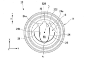
図8は、第2実施形態のノズルキャップ27を軸線方向から見た上面図である。
ノズルキャップ27は、図8に示すように、樋状部24の内側に設けられた注出用開口孔23Bのうち、樋状部24によって囲まれた第1開口28から主に内容物が流出し、樋状部24の開口端24a,24aよりも径方向外側(+X側)に位置する部分が主に空気置換孔25として機能する。
ノズルキャップ27は、図8に示すように、樋状部24の内側に設けられた注出用開口孔23Bのうち、樋状部24によって囲まれた第1開口28から主に内容物が流出し、樋状部24の開口端24a,24aよりも径方向外側(+X側)に位置する部分が主に空気置換孔25として機能する。
空気置換孔25は、Y方向両側に設けられた第2流出規制部29Bによって傾倒時に上側となる方向に向かって注出用開口孔23Bよりも開口幅が漸次縮寸されている。
本実施形態のノズルキャップ27では、注出用開口孔23Bのうち、樋状部24によって囲まれた周縁に沿ってその全体に第1流出規制部29Aが設けられた構成とされている。つまり、樋状部24の内壁面24bの全体に亘って第1流出規制部29Aが形成されている。第1流出規制部29Aは、樋状部24の内壁面24bと第1開口28との間に存在し、第1開口28の周縁が樋状部24の内壁面24bから離れている。
第1流出規制部29Aは、注出用開口孔23Bの第1開口28の周縁に沿って略均一な幅Wで設けられている。第1流出規制部29Aの幅Wは、内容物の粘性等に応じて適宜設定される。なお、第1流出規制部29Aの幅Wは、第1開口28の周辺に亘って一定でなくてもよく、部分的に幅寸法が変化していてもよい。
本実施形態の構成によれば、樋状部24の内壁面24bに沿って第1流出規制部29Aを設けたことによって、注出用開口孔23Bのうち第1開口28が樋状部24の内壁面24bから離れた構成となり、第1実施形態の構成よりも、注出用開口孔23Bから内容物が注出してから樋状部24の内壁面24bに接するまでの時間を稼ぐことができる。
本実施形態のノズルキャップ27によれば、第1流出規制部29Aにより、注出用開口孔23を通過した内容物の略全体が樋状部24の内壁面24bに接触するタイミングをさらに遅らせることができる。これによって、ノズル流路18内を流動する内容物の流下速度がさらに速まり、内容物の注出効率を高めることができる。
[第3実施形態]
次に、本発明の第3実施形態のノズルキャップ30の構成について説明する。
以下に示す本実施形態のノズルキャップ30の基本構成は、上記第2実施形態と略同様であるが、一対の流出規制部29Cが、樋状部24によって囲まれた注出用開口孔23Cの周縁のうち傾倒時に下側となる領域を除いて注出用開口孔23CのY方向両側にそれぞれ形成されている点において異なる。よって、以下の説明では、上記実施形態と異なる点について詳しく説明し、共通な箇所の説明は省略する。また、説明に用いる各図面において、図8と共通の構成要素には同一の符号を付すものとする。
次に、本発明の第3実施形態のノズルキャップ30の構成について説明する。
以下に示す本実施形態のノズルキャップ30の基本構成は、上記第2実施形態と略同様であるが、一対の流出規制部29Cが、樋状部24によって囲まれた注出用開口孔23Cの周縁のうち傾倒時に下側となる領域を除いて注出用開口孔23CのY方向両側にそれぞれ形成されている点において異なる。よって、以下の説明では、上記実施形態と異なる点について詳しく説明し、共通な箇所の説明は省略する。また、説明に用いる各図面において、図8と共通の構成要素には同一の符号を付すものとする。
図9は、第3実施形態のノズルキャップ30を軸線方向から見た上面図である。
本実施形態のノズルキャップ30は、図9に示すように、ノズル部13の樋状部24によって囲まれた注出用開口孔23Cの周縁のうち、樋状部24の頂部q側の周縁部分23cを除く他の周縁部分23d,23dに沿って、一対の流出規制部29C,29Cが設けられている。注出用開口孔23Cの周縁部分23cは、樋状部24の内壁面24bと一致する。
本実施形態のノズルキャップ30は、図9に示すように、ノズル部13の樋状部24によって囲まれた注出用開口孔23Cの周縁のうち、樋状部24の頂部q側の周縁部分23cを除く他の周縁部分23d,23dに沿って、一対の流出規制部29C,29Cが設けられている。注出用開口孔23Cの周縁部分23cは、樋状部24の内壁面24bと一致する。
本実施形態のノズルキャップ30では、注出用開口孔23Cの周縁のうち、樋状部24の頂部q側の周縁部分23cを除いて流出規制部29Cを設ける構成とした。傾倒時に下側になる周縁部分23cを除いて流出規制部29Cを設けることで、注出用開口孔23を通過する際に内容物が流出規制部29Cを乗り上げる必要がなくなり、使用時における容器本体100Aの傾倒角度の上昇を招くことなく、内容物が注出用開口孔23から樋状部24のノズル流路18内へ至る時間を短縮することができる。注出用開口孔23の周縁部分23cを通過した内容物は、その重力によって傾斜したノズル流路18内を流下していく。
一方、注出用開口孔23の周縁部分23d,23d、つまり流出規制部29C,29Cの間を通過した内容物は、各流出規制部29Cによってノズル流路18の入口付近での拡がりが抑えられ、樋状部24の内壁面24bに接するタイミングを遅らせることができる。
このように、本実施形態の構成では、使用時に容器本体100Aを傾ける角度が大きくなるのを抑えて、重力に従って流下する内容物の流出性を向上させることができる。これとともに、内壁面24bに対する内容物の粘性摩擦による影響を減らし、流動損失を抑えることによって、内容物全体の流下速度を速めることができる。
[第4実施形態]
次に、本発明の第4実施形態のノズルキャップ40の構成について説明する。
以下に示す本実施形態のノズルキャップ40の基本構成は、上記第3実施形態と略同様であるが、本実施形態では、流出規制部29Dが、樋状部24によって囲まれた注出用開口孔23Dの周縁のうちの1/2の領域にだけ設けられている点において異なる。よって、以下の説明では、上記実施形態と異なる点について詳しく説明し、共通な箇所の説明は省略する。また、説明に用いる各図面において、図9と共通の構成要素には同一の符号を付すものとする。
次に、本発明の第4実施形態のノズルキャップ40の構成について説明する。
以下に示す本実施形態のノズルキャップ40の基本構成は、上記第3実施形態と略同様であるが、本実施形態では、流出規制部29Dが、樋状部24によって囲まれた注出用開口孔23Dの周縁のうちの1/2の領域にだけ設けられている点において異なる。よって、以下の説明では、上記実施形態と異なる点について詳しく説明し、共通な箇所の説明は省略する。また、説明に用いる各図面において、図9と共通の構成要素には同一の符号を付すものとする。
図10は、第4実施形態のノズルキャップ40を軸線方向から見た上面図である。
本実施形態のノズルキャップ40では、図10に示すように、樋状部24によって囲まれた注出用開口孔23Dの周縁のうち、樋状部24の頂部q側の周縁部分23cとその両側の周縁部分23e,23eを除いた他の周縁部分23f,23fに、一対の流出規制部29D,29Dが形成されている。
本実施形態のノズルキャップ40では、図10に示すように、樋状部24によって囲まれた注出用開口孔23Dの周縁のうち、樋状部24の頂部q側の周縁部分23cとその両側の周縁部分23e,23eを除いた他の周縁部分23f,23fに、一対の流出規制部29D,29Dが形成されている。
流出規制部29Dは、注出用開口孔23Dのうち、樋状部24によって囲まれた部分の約1/2の領域、ここでは、図10の紙面における上半分(+X側)の周縁部分23f,23fにだけ設けられている。具体的に流出規制部29Dは、樋状部24の各開口端24aから所定の領域に亘って形成されている。流出規制部29Dの形成領域は、内容物の種類などに応じて適宜設定される。本実施形態では、流出規制部29Dの端部29dが軸線Cよりも-X側に位置しているが、+X側に位置していてもよい。
流出規制部29D,29Dは、注出用開口孔23Dの+X側へ行くに従って互いに近づく方向へ拡がり、X方向に対して湾曲した周縁部分23f、23fを構成する。
注出用開口孔23Dは、3つの開口領域(空気置換孔25、第1開口28A、第2開口28B)からなり、傾倒時に上側となる方向から開口面積が小さい順にX方向に並んでいる(空気置換孔25の開口面積<第1開口28Aの開口面積<第2開口28Bの開口面積)。
ここで、空気置換孔25は、注出用開口孔23Dのうち底面部22の第2傾斜面22Bに形成された領域の開口である。第1開口28Aは、注出用開口孔23Dのうち底面部22の第1傾斜面22Aに形成され、一対の流出規制部29D,29Dの間の領域の開口である。第2開口28Bは、注出用開口孔23Dのうち底面部22の第1傾斜面22Aに形成され、一対の流出規制部29D,29Dの間の領域を除く領域の開口である。
傾倒時に最下位となる第2開口28Bの開口面積を広く取ることによって、自重によって流出する内容物を多く流出させることができる。また、流出規制部29D,29Dによって、ノズル流路18のうち、流出規制部29D,29Dの間の第1開口28Aから流出した内容物、つまり、樋状部24の開放側を流動する内容物が内壁面24bに接するタイミングを遅らせることができる。これにより、内壁面24bに対する粘性摩擦の影響を抑えて、ノズル流路18を流れる内容物の流下速度を速めることができ、内容物の注出性を改善することができる。
以上、添付図面を参照しながら本発明に係る好適な実施形態について説明したが、本発明は係る例に限定されないことは言うまでもない。当業者であれば、特許請求の範囲に記載された技術的思想の範疇内において、各種の変更例または修正例に想到し得ることは明らかであり、それらについても当然に本発明の技術的範囲に属するものと了解される。
例えば、注出用開口孔の形状、流出規制部を設ける範囲、形状、大きさ等は、上述した各実施形態の形状に限られることはなく、内容物の種類等に応じて適宜変更が可能である。
本発明は、キャップに適用できる。
29、29A,29B,29C,29D…流出規制部、10…ノズルキャップ(キャップ)、11…嵌合部、12…ノズル基部、13…ノズル部、22…底面部、23,23B,23C,23D…注出用開口孔、23c…周縁部分、24a…開口端、25…空気置換孔、100…容器、100A…容器本体、101…口部
Claims (6)
- 粘性を有する液状の内容物を収容する容器本体の口部に着脱可能に装着され前記内容物を傾倒注出するキャップであって、
前記口部に嵌合する嵌合部と、
前記嵌合部の内側に同軸をなして設けられ底面部に注出用開口孔を有するノズル基部と、
前記注出用開口孔の少なくとも一部を囲むように前記底面部に立設され前記容器本体とは反対側に延出するノズル部と、を備え、
前記ノズル部の内側には、前記注出用開口孔のうち前記ノズル部によって囲まれた周縁の少なくとも一部に流出規制部が設けられている、キャップ。 - 前記流出規制部は、前記注出用開口孔のうち前記ノズル部によって囲まれた周縁全体に設けられている、請求項1に記載のキャップ。
- 前記流出規制部は、前記注出用開口孔のうち少なくとも傾倒時に下側になる周縁部分を除く他の周縁部分に設けられている、請求項1に記載のキャップ。
- 前記流出規制部は、前記注出用開口孔のうち前記ノズル部によって囲まれた周縁の1/2の領域に設けられている、請求項1に記載のキャップ。
- 前記流出規制部は、前記注出用開口孔のうち傾倒時に上側となる方向へ前記注出用開口孔を漸次縮寸するように設けられている、請求項1から4のいずれか一項に記載のキャップ。
- 前記ノズル部は、軸方向に交差する径方向の一端側に開口するU字形状をなす、請求項1から5のいずれか一項に記載のキャップ。
Priority Applications (2)
| Application Number | Priority Date | Filing Date | Title |
|---|---|---|---|
| CN201880010885.XA CN110291018B (zh) | 2017-02-16 | 2018-02-01 | 盖子 |
| KR1020197019754A KR102626529B1 (ko) | 2017-02-16 | 2018-02-01 | 캡 |
Applications Claiming Priority (2)
| Application Number | Priority Date | Filing Date | Title |
|---|---|---|---|
| JP2017026852A JP6895764B2 (ja) | 2017-02-16 | 2017-02-16 | キャップ |
| JP2017-026852 | 2017-02-16 |
Publications (1)
| Publication Number | Publication Date |
|---|---|
| WO2018150892A1 true WO2018150892A1 (ja) | 2018-08-23 |
Family
ID=63169330
Family Applications (1)
| Application Number | Title | Priority Date | Filing Date |
|---|---|---|---|
| PCT/JP2018/003420 Ceased WO2018150892A1 (ja) | 2017-02-16 | 2018-02-01 | キャップ |
Country Status (4)
| Country | Link |
|---|---|
| JP (1) | JP6895764B2 (ja) |
| KR (1) | KR102626529B1 (ja) |
| CN (1) | CN110291018B (ja) |
| WO (1) | WO2018150892A1 (ja) |
Citations (4)
| Publication number | Priority date | Publication date | Assignee | Title |
|---|---|---|---|---|
| JP2009286465A (ja) * | 2008-05-30 | 2009-12-10 | Yoshino Kogyosho Co Ltd | ヒンジキャップ |
| JP2011136764A (ja) * | 2009-12-04 | 2011-07-14 | Kao Corp | 注出容器 |
| JP2013209143A (ja) * | 2012-03-30 | 2013-10-10 | Yoshino Kogyosho Co Ltd | 注出キャップ |
| JP2013209134A (ja) * | 2012-03-30 | 2013-10-10 | Yoshino Kogyosho Co Ltd | 合成樹脂製注出キャップ |
Family Cites Families (7)
| Publication number | Priority date | Publication date | Assignee | Title |
|---|---|---|---|---|
| CN1103725C (zh) * | 1998-05-22 | 2003-03-26 | 株式会社吉野工业所 | 合成树脂制的液体注出容器的瓶塞与盖子 |
| JP5305801B2 (ja) | 2008-09-17 | 2013-10-02 | ライオン株式会社 | 液体注出容器 |
| JP5538193B2 (ja) * | 2009-12-04 | 2014-07-02 | 花王株式会社 | 注出容器 |
| JP5669486B2 (ja) | 2010-09-07 | 2015-02-12 | ライオン株式会社 | 液体注出容器 |
| CH704476A1 (de) * | 2011-02-15 | 2012-08-15 | Alpla Werke | Kunststoffbehälter mit einem Ausgiesser. |
| JP5934589B2 (ja) * | 2012-07-02 | 2016-06-15 | ライオン株式会社 | キャップ及びキャップ部構造 |
| CN205819909U (zh) * | 2016-06-22 | 2016-12-21 | 湖南新金浩茶油股份有限公司 | 食用油瓶盖 |
-
2017
- 2017-02-16 JP JP2017026852A patent/JP6895764B2/ja active Active
-
2018
- 2018-02-01 KR KR1020197019754A patent/KR102626529B1/ko active Active
- 2018-02-01 WO PCT/JP2018/003420 patent/WO2018150892A1/ja not_active Ceased
- 2018-02-01 CN CN201880010885.XA patent/CN110291018B/zh active Active
Patent Citations (4)
| Publication number | Priority date | Publication date | Assignee | Title |
|---|---|---|---|---|
| JP2009286465A (ja) * | 2008-05-30 | 2009-12-10 | Yoshino Kogyosho Co Ltd | ヒンジキャップ |
| JP2011136764A (ja) * | 2009-12-04 | 2011-07-14 | Kao Corp | 注出容器 |
| JP2013209143A (ja) * | 2012-03-30 | 2013-10-10 | Yoshino Kogyosho Co Ltd | 注出キャップ |
| JP2013209134A (ja) * | 2012-03-30 | 2013-10-10 | Yoshino Kogyosho Co Ltd | 合成樹脂製注出キャップ |
Also Published As
| Publication number | Publication date |
|---|---|
| CN110291018A (zh) | 2019-09-27 |
| JP6895764B2 (ja) | 2021-06-30 |
| CN110291018B (zh) | 2021-03-23 |
| KR102626529B1 (ko) | 2024-01-18 |
| JP2018131240A (ja) | 2018-08-23 |
| KR20190118552A (ko) | 2019-10-18 |
Similar Documents
| Publication | Publication Date | Title |
|---|---|---|
| US10081463B2 (en) | Multi-chambered bottle with metering stage, pour spout and cap | |
| JP5669486B2 (ja) | 液体注出容器 | |
| JP2010070203A (ja) | 液体注出容器 | |
| JP2016210440A (ja) | 液吐出容器 | |
| WO2018150892A1 (ja) | キャップ | |
| JP2013173548A (ja) | 中空容器 | |
| JP2011046445A (ja) | 注出容器 | |
| JP2017154749A (ja) | 液体計量容器 | |
| JP6842945B2 (ja) | キャップ | |
| JP5974427B2 (ja) | キャップ | |
| HK40013439A (en) | Cap | |
| HK40013439B (zh) | 盖子 | |
| WO2018150909A1 (ja) | キャップ | |
| JP6001417B2 (ja) | スリットバルブ付き注出中栓 | |
| JP2019119522A (ja) | 注出容器 | |
| JP5781404B2 (ja) | 泡噴出容器 | |
| JP6903480B2 (ja) | 注出具 | |
| JP2011136703A (ja) | 注出容器 | |
| JP5313790B2 (ja) | 注出具 | |
| JP6104153B2 (ja) | 液注出容器 | |
| JP2019123511A (ja) | キャップ | |
| JP6084405B2 (ja) | 注出栓 | |
| HK40012908B (en) | Cap | |
| JP5103302B2 (ja) | 計量キャップ | |
| JP2025103167A (ja) | 注出部材 |
Legal Events
| Date | Code | Title | Description |
|---|---|---|---|
| 121 | Ep: the epo has been informed by wipo that ep was designated in this application |
Ref document number: 18754009 Country of ref document: EP Kind code of ref document: A1 |
|
| ENP | Entry into the national phase |
Ref document number: 20197019754 Country of ref document: KR Kind code of ref document: A |
|
| NENP | Non-entry into the national phase |
Ref country code: DE |
|
| 122 | Ep: pct application non-entry in european phase |
Ref document number: 18754009 Country of ref document: EP Kind code of ref document: A1 |