WO2018147371A1 - 電動パワーステアリング装置 - Google Patents
電動パワーステアリング装置 Download PDFInfo
- Publication number
- WO2018147371A1 WO2018147371A1 PCT/JP2018/004398 JP2018004398W WO2018147371A1 WO 2018147371 A1 WO2018147371 A1 WO 2018147371A1 JP 2018004398 W JP2018004398 W JP 2018004398W WO 2018147371 A1 WO2018147371 A1 WO 2018147371A1
- Authority
- WO
- WIPO (PCT)
- Prior art keywords
- angle
- steering
- target
- electric power
- power steering
- Prior art date
Links
Images


Classifications
-
- B—PERFORMING OPERATIONS; TRANSPORTING
- B62—LAND VEHICLES FOR TRAVELLING OTHERWISE THAN ON RAILS
- B62D—MOTOR VEHICLES; TRAILERS
- B62D5/00—Power-assisted or power-driven steering
- B62D5/04—Power-assisted or power-driven steering electrical, e.g. using an electric servo-motor connected to, or forming part of, the steering gear
- B62D5/0457—Power-assisted or power-driven steering electrical, e.g. using an electric servo-motor connected to, or forming part of, the steering gear characterised by control features of the drive means as such
- B62D5/046—Controlling the motor
- B62D5/0463—Controlling the motor calculating assisting torque from the motor based on driver input
-
- B—PERFORMING OPERATIONS; TRANSPORTING
- B62—LAND VEHICLES FOR TRAVELLING OTHERWISE THAN ON RAILS
- B62D—MOTOR VEHICLES; TRAILERS
- B62D5/00—Power-assisted or power-driven steering
- B62D5/04—Power-assisted or power-driven steering electrical, e.g. using an electric servo-motor connected to, or forming part of, the steering gear
- B62D5/0409—Electric motor acting on the steering column
-
- B—PERFORMING OPERATIONS; TRANSPORTING
- B62—LAND VEHICLES FOR TRAVELLING OTHERWISE THAN ON RAILS
- B62D—MOTOR VEHICLES; TRAILERS
- B62D6/00—Arrangements for automatically controlling steering depending on driving conditions sensed and responded to, e.g. control circuits
- B62D6/008—Control of feed-back to the steering input member, e.g. simulating road feel in steer-by-wire applications
Definitions
- the present invention controls the torsion angle of a torsion bar provided on a column shaft (steering shaft, steering wheel shaft) so as to follow a value corresponding to vehicle driving information such as a steering angle, a vehicle speed, and a steering state.
- vehicle driving information such as a steering angle, a vehicle speed, and a steering state.
- the present invention relates to a high-performance electric power steering device that achieves a desired steering torque, is not affected by road conditions, and is not affected by changes in mechanical system characteristics (friction, motor output characteristics, etc.) over time.
- an electric power steering device as a device equipped with a motor control device, and the electric power steering device applies an assisting force (steering assisting force) to the steering system of the vehicle by the rotational force of the motor.
- the driving force of the motor controlled by the supplied power is applied to the steering shaft or the rack shaft by a transmission mechanism including a speed reduction mechanism.
- Such a conventional electric power steering apparatus performs feedback control of the motor current in order to generate the assist force accurately.
- the motor applied voltage is adjusted so that the difference between the steering assist command value (current command value) and the motor current detection value is small. This is done by adjusting the duty of modulation) control.
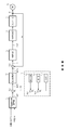
- the column shaft 2 having a torsion bar is provided with a torque sensor 10 for detecting the steering torque Ts of the handle 1 and a rudder angle sensor 14 for detecting the steering angle ⁇ h, and a motor for assisting the steering force of the handle 1. 20 is connected to the column shaft 2 via the speed reduction mechanism 3.
- the control unit (ECU) 30 that controls the electric power steering apparatus is supplied with electric power from the battery 13 and also receives an ignition key signal via the ignition key 11.
- the control unit 30 calculates a current command value of an assist (steering assist) command based on the steering torque Ts detected by the torque sensor 10 and the vehicle speed Vs detected by the vehicle speed sensor 12, and compensates the current command value.
- the current supplied to the EPS motor 20 is controlled by the voltage control command value Vref subjected to.
- the control unit 30 is connected to a CAN (Controller Area Network) 40 that exchanges various vehicle information, and the vehicle speed Vs can be received from the CAN 40.
- the control unit 30 can be connected to a non-CAN 41 that exchanges communications, analog / digital signals, radio waves, and the like other than the CAN 40.
- the control unit 30 is mainly composed of a CPU (including MCU, MPU, etc.), and general functions executed by programs in the CPU are as shown in FIG.
- the function and operation of the control unit 30 will be described with reference to FIG. 2.
- the steering torque Ts detected by the torque sensor 10 and the vehicle speed Vs detected by the vehicle speed sensor 12 (or from the CAN 40) are represented by the current command value Iref1.
- the current command value calculation unit 31 to be calculated is input.
- the current command value calculation unit 31 calculates a current command value Iref1, which is a control target value of the current supplied to the motor 20, using an assist map or the like based on the input steering torque Ts and vehicle speed Vs.
- the voltage control command value Vref whose characteristics are improved by the PI control unit 35 is input to the PWM control unit 36, and the motor 20 is PWM driven via an inverter 37 as a drive unit.
- the current value Im of the motor 20 is detected by the motor current detector 38 and fed back to the subtraction unit 32B.
- a compensation signal CM from the compensation signal generator 34 is added to the adder 32A, and the compensation of the steering system system is performed by adding the compensation signal CM to improve the convergence and inertia characteristics.
- Compensation signal generation unit 34 adds self-aligning torque (SAT) 34-3 and inertia 34-2 by addition unit 34-4, and further adds convergence 34-1 to the addition result by addition unit 34-5.
- the addition result of the adder 34-5 is used as the compensation signal CM.
- the steering torque (torsion torque of the torsion bar) applied by the driver's manual input is detected by the torque sensor, and the motor current is mainly controlled as the assist current according to the torque.
- the steering torque may vary depending on the steering angle due to a difference in road surface condition (for example, inclination).
- the steering characteristics differ depending on the variation of the motor output characteristics due to the aging products.
- Patent Document 1 discloses a vehicle control apparatus that solves this problem.
- the device of Patent Document 1 has a steering torque target value set by the steering angle detection means, the target setting means, and the target setting means so that an appropriate steering torque based on the tactile characteristics of the driver can be given. And control means for controlling so as to be realized.
- the apparatus of Patent Document 1 uses PI control for the deviation between the target value of the steering torque and the detected steering torque.
- the present invention has been made under the circumstances as described above, and the object of the present invention is not affected by the road surface condition, but depends on changes in the mechanical characteristics of the steering system (friction, motor output characteristics, etc.) over time. It is an object of the present invention to provide an electric power steering apparatus capable of easily realizing an equivalent steering torque for vehicle driving information such as a steering angle.
- the present invention relates to an electric power steering apparatus that includes a torsion bar on a column shaft of a steering wheel of a vehicle, and that drives and controls a motor connected to the column shaft based on a current command value, thereby assisting a steering system.
- the object of the present invention is to provide a target steering torque generator for generating a target steering torque based on vehicle driving information, a converter for converting the target torque into a target twist angle, and a twist of the torsion bar with respect to the target twist angle.
- a torsion angle control unit that calculates the current command value that causes the angle to follow, and is achieved by controlling the detected torque of the torsion bar to follow the value corresponding to the vehicle driving information.
- the object of the present invention is based on the target column angular velocity 1 and the torsion angle feedback compensation unit in which the torsion angle control unit outputs the target column angular velocity 1 with respect to the target torsion angle and the deviation of the torsion angle. Or a torsion angle disturbance compensator for outputting a target column angular velocity 2 with respect to the vehicle driving information.
- An angular velocity conversion unit that converts the motor angular velocity into a column angular velocity, or in the torsion angle control unit, a target column angular velocity 3 that is an added value of the target column angular velocities 1 and 2 is added to the velocity control unit.
- the torsion angle control unit further sets a transfer function for the motor angular velocity to improve the stability of the entire system
- the torsion angle control unit further sets a transfer function with respect to the torsion angle to
- the torsion angle control unit further includes a stabilization compensator that improves the stability of the entire system by setting a transfer function for the column angle.
- the transfer function is a second-order filter or a fourth-order filter, or the target steering torque generator is operated to turn the steering wheel to the right or left.
- the target steering torque generation unit When a state is input or when the target steering torque generation unit outputs a vehicle speed sensitive torque signal 1 according to the vehicle driving information, and a vehicle speed sensitive damper gain in a differential value of the vehicle driving information.
- a damper gain unit that outputs a torque signal 2, a hysteresis correction unit that corrects the vehicle driving information according to the steering state and outputs a torque signal 3, the torque signal 1, and the torque signal 2 and an output unit that outputs at least one of the torque signals 3 and outputs the target steering torque, or the vehicle speed sensitive damper gain is gradually increased according to the vehicle speed.
- the hysteresis correction unit corrects the vehicle driving information by using a function.
- the function is switched between when the steering state is turned to the right and when the steering is turned to the left, and when the function is switched, the offset adjustment value for the vehicle driving information is updated, or the offset
- the adjustment value is calculated using the vehicle driving information and the previous value of the torque signal 3, or the limiter for limiting the upper and lower limit values is provided at the subsequent stage of the speed control unit, or
- the torsion angle feedback compensation unit is a gain value of a transfer function, or the rudder angle disturbance compensation unit suppresses the influence on the torsion angle due to a change in the vehicle operation information, and the target torsion for sudden steering
- the value of the transfer function that improves the followability of the torsion angle to the angle, or the value of the transfer function of the rudder angle disturbance compensation unit By determined from the frequency transfer function of the vehicle system model, or the vehicle driving information is a steering angle, vehicle speed, by a steering state, is more effectively
- the target twist angle is generated from the vehicle driving information such as the steering state of the right / left steering of the steering wheel, the vehicle speed, and the steering angle, and the target twist angle and the detected twist angle are calculated.
- the deviation for example, by controlling the speed by using the result obtained by multiplying the deviation by a compensation value (transfer function) as the target column speed
- the operation is performed so that the torsion angle follows the target torsion angle.
- a desired steering torque can be realized for vehicle driving information such as the above.
- the influence of the torsion bar torsion angle due to changes in the steering angle input from the driver is suppressed, and the torsion angle follows the target torsion angle for sudden steering. It is possible to further improve the performance.
- the present invention is an electric power steering device for realizing an equivalent steering torque for vehicle driving information such as a steering angle, a vehicle speed, and a steering state without being affected by a road surface state, and is provided in a column shaft.
- a desired steering torque is realized by controlling the torsion angle of the torsion bar so as to follow a value corresponding to the vehicle driving information.
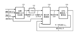
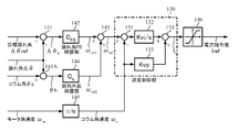
- FIG. 3 is a block diagram showing the basic configuration of the present invention.
- the steering of the driver is assisted by a motor in the EPS steering system / vehicle system 100.
- the target steering torque generation unit 120 that outputs the target steering torque T ref according to the vehicle driving information such as the steering angle ⁇ h is inputted with the steering state STs of the right or left steering, the vehicle speed Vs, and the steering angle ⁇ h.
- the target steering torque T ref generated by the target steering torque generation unit 120 is converted by the conversion unit 101 having the characteristic of “1 / K tor ”, where the spring constant of the torsion bar 2A provided on the column shaft 2 is K tor.
- the target twist angle ⁇ ref is converted into the target twist angle ⁇ ref and the target twist angle ⁇ ref is input to the twist angle control unit 140.
- the torsion angle control unit 140 receives the target torsion angle ⁇ ref , the steering angle ⁇ h, the torsion angle ⁇ , and the motor angular velocity ⁇ m, and the torsion angle control unit 140 sets the torsion angle ⁇ to the target torsion angle ⁇ ref.
- the current command value I ref is calculated, and the EPS motor is driven by the current command value I ref .
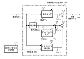
- FIG. 4 An installation example of the EPS steering system and various sensors is as shown in FIG. 4, and the column shaft 2 is provided with a torsion bar 2A.
- a road surface reaction force Fr and road surface information ⁇ act on the steering wheels 8L and 8R, and an upper angle sensor (angle ⁇ 1 ) is provided on the handle side of the column shaft 2 with the torsion bar 2A interposed therebetween.
- a lower angle sensor (angle ⁇ 2 ) is provided on the steering wheel side of the column shaft 2 with being sandwiched.
- Steering angle ⁇ h is detected by the steering angle sensor provided in the upper portion of the column shaft 2, from the angle theta 1 and the angle theta 2 of the deviation of the lower angle sensor of the upper angle sensor, torsional torsion bar by the following Equations 1 and 2
- the angle ⁇ and the torsion bar torque Tt can be obtained.
- K tor is the spring constant of the torsion bar 2A.
- the torsion bar torque Tt can be detected using a torque sensor disclosed in, for example, Japanese Patent Application Laid-Open No. 2008-216172. Further, the steering state STs of the right turn or left turn of the steering can be obtained by the relationship between the steering angle ⁇ h and the motor angular velocity ⁇ m as shown in FIG. 5, for example.
- the steering angle ⁇ h, the steering state STs, and the vehicle speed Vs are input to the target steering torque generator 120 (step S1), and the target steering torque generator 120 generates the target steering torque T ref (step S10).
- the target steering torque T ref is input to the conversion unit 101, and converted to the target twist angle ⁇ ref by the conversion unit 101 (step S30).
- the target torsion angle ⁇ ref , the steering angle ⁇ h, the torsion angle ⁇ , and the motor angular velocity ⁇ m are input to the torsion angle control unit 140 (step S31), and the torsion angle control unit 140 follows the target torsion angle ⁇ ref .
- the current command value I ref is calculated (step S40), the motor is driven based on the current command value I ref , and current control is performed (step S60).
- FIG. 7 shows a configuration example of the target steering torque generation unit 120.
- the steering angle ⁇ h is input to the basic map 121, the differentiation unit 122, and the hysteresis correction unit 124.
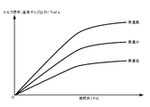
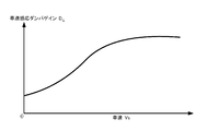
- the basic map 121 shows the vehicle speed Vs as shown in FIG.
- a torque signal T ref — a having as a parameter is output.
- the map is constituted by the absolute value
- the torque signal T ref — a is input to the adding unit 126.
- the steering angle speed ⁇ h obtained by differentiating the steering angle ⁇ h is output from the differentiation unit 122, and the steering angle speed ⁇ h is input to the multiplication unit 125.
- Vehicle speed sensitive damper gain D G is output depending from the damper gain map 123 of vehicle speed sensitive to vehicle speed Vs, a gradually increases characteristics as the vehicle speed Vs is high, for example, as shown in FIG.
- the damper gain map 123 and the multiplication unit 125 constitute a damper gain unit.
- the right turn / left turn determination unit 110 performs the determination as shown in FIG. 5, for example, and inputs the steering state STs as the determination result to the hysteresis correction unit 124.
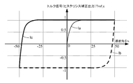
- the steering angle ⁇ h is input to the hysteresis correction unit 124, and the hysteresis correction unit 124 calculates a torque signal T ref_c according to the following equation 3 based on the steering angle ⁇ h and the steering state STs.
- x ⁇ h
- y R T ref_c
- y L T ref_c, a> 1, c> 0.
- Equation 4 the x1 to x in Formula 3, can be derived by substituting y1 to y R and y L.
- Equation 3 and Equation 4 become Equation 5 and Equation 6 below.
- An example of a diagram of the torque signal T ref — c is shown in FIG. That is, the torque signal T ref — c from the hysteresis correction unit 124 has a hysteresis characteristic such as 0 origin ⁇ la (thin line) ⁇ lb (dashed line) ⁇ lc (thick line).
- the determination method in the right / left turn determination unit 110 is not limited to the determination as shown in FIG. For example, it is determined whether the current value of the steering angle ⁇ h has changed in the plus direction (increment is 0 or more) with respect to the past value, or has changed in the minus direction (increment is less than 0), and is determined based on the direction. You may do it. Also, instead of the steering angle [theta] h, it may be used angle theta 1 of the upper angle sensor.
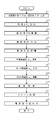
- step S10 in FIG. 6 an operation example of the target steering torque generation unit 120 (step S10 in FIG. 6) will be described with reference to the flowchart in FIG.
- the steering angle ⁇ h and the vehicle speed Vs are input (step S11), and the basic map 121 generates and outputs a torque signal T ref_a corresponding to the steering angle ⁇ h and the vehicle speed Vs according to the characteristics of FIG. 8 (step S12).
- Steering angle ⁇ h is also input to the differential unit 122 and the hysteresis correction unit 124, the differential unit 122 by differentiating the steering angle ⁇ h outputs steering angular velocity omega h (step S13), and the damper gain map 123 corresponding to the vehicle speed Vs and it outputs a vehicle speed sensitive damper gain D G (step S14), and the multiplication unit 125 calculates a torque signal T REF_B by multiplying the steering angular velocity omega h and vehicle speed sensitive damper gain D G, and inputs the torque signal T REF_B to the adding unit 127 (Step S15).
- the right turn / left turn determination unit 110 determines whether the steering is turned right / left, and inputs a steering state STs as a determination result to the hysteresis correction unit 124 (step S16).
- the hysteresis correction unit 124 performs the hysteresis correction by calculating the equations 5 and 6 with respect to the steering angle ⁇ h and depending on the steering state STs (step S17), and generates the torque signal T ref_c (step S18). .
- the torque signal T ref_c is input to the adder 127.
- the torque signal T ref_a , torque signal T ref_b , and torque signal T ref_c obtained as described above are added by the adding units 126 and 127 constituting the output unit, and the target steering torque T ref is calculated (step S19). . That is, the torque signal T ref_b and the torque signal T ref_c are added by the adding unit 127, the torque signal T ref_a is added to the addition result by the adding unit 126, and the addition result is output as the target steering torque T ref .
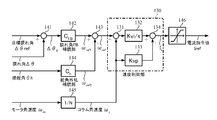
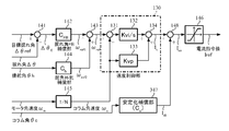
- the 12 is a block diagram showing a configuration example (first embodiment) of the torsion angle control unit 140.
- a deviation ⁇ 0 between the target torsion angle ⁇ ref and the torsion angle ⁇ is calculated by the subtraction unit 141, and the deviation ⁇ 0 is calculated.
- the twist angle FB compensator 142 multiplies the deviation ⁇ 0 by a compensation value C FB (transfer function), and outputs a target column angular velocity ⁇ ref1 such that the twist angle ⁇ follows the target twist angle ⁇ ref .
- the target column angular velocity ⁇ ref1 is input to the adding unit 143.
- the compensation value C FB may be a simple gain K pp or a PI control compensation value.
- the steering angle ⁇ h is input to the steering angle disturbance compensation unit 144 for the compensation value Ch (transfer function), and the steering angle ⁇ h is multiplied by the compensation value Ch (transfer function) to output the target column angular velocity ⁇ ref2 .
- the steering angle disturbance compensation 144 the influence of the change in the steering angle ⁇ h input from the driver on the torsion bar torsion angle ⁇ is suppressed, and the followability of the torsion angle ⁇ to the target torsion angle ⁇ ref with respect to sudden steering. Can be improved.
- the target column angular velocity ⁇ ref1 and the target column angular velocity ⁇ ref2 are added by the adder 143 to become the target column angular velocity ⁇ ref .
- the target column angular velocity ⁇ ref is input to the speed control unit 130 of the IP control (proportional advance type PI control).
- the steering angle ⁇ h by the steering of the driver is changed, it will impact on the torsional angle [Delta] [theta] as a disturbance, deviation occurs with respect to the target torsion angle [Delta] [theta] ref. This is especially true for sudden steering.
- the basic purpose of the steering angle disturbance compensation unit 144 is to reduce the influence of the steering angle ⁇ h as this disturbance. Further, the transfer function Ch of the rudder angle disturbance compensation unit 144 can be determined from the frequency transfer characteristics of a plant model, which will be described later, thereby suppressing the influence of disturbance.
- the speed control unit 130 of the IP control calculates a current command value Is such that the column angular speed ⁇ c follows the target column angular speed ⁇ ref .
- the column angular velocity ⁇ c may be a value obtained by multiplying the motor angular velocity ⁇ m by the reduction ratio “1 / N” of the reduction ratio unit 145 that is a reduction mechanism.
- a limiter 146 that limits the upper and lower limit values of the current command value Is from the speed control unit 130 and outputs the current command value I ref is provided at the subsequent stage of the speed control unit 130.
- step S40 in FIG. 6 an operation example (step S40 in FIG. 6) of the torsion angle control unit 140 will be described with reference to the flowchart in FIG.
- the target twist angle ⁇ ref and the twist angle ⁇ are input (step S41), and the deviation ⁇ 0 is calculated by the subtracting unit 141 (step S42). Deviation ⁇ 0 is input to and compensated for torsion angle FB compensation unit 142 (step S43), and compensated target column angular velocity ⁇ ref1 is input to addition unit 143.
- the steering angle ⁇ h is input (step S44), the steering angle ⁇ h is input to the steering angle disturbance compensation unit 144 and compensated (step S45), and the compensated target column angular velocity ⁇ ref2 is input to the addition unit 143 (step S45). Step S46).
- the target column angular velocity ⁇ ref which is the addition result of the adding unit 143 is input to the speed control unit 130.
- the motor angular velocity ⁇ m is multiplied by “1 / N” by the reduction ratio unit 145 (step S47), and the column angular velocity ⁇ c as a multiplication result is input to the speed control unit 130 (step S48).
- the difference between the target column angular velocity ⁇ ref and the column angular velocity ⁇ c is obtained by the subtracting unit 131, and the difference is integrated (Kvi / s) by the integrating unit 132 and input to the adding unit 134 (step S50).
- the column angular velocity ⁇ c is proportionally processed (Kvp) by the proportional unit 133, the proportional result is input to the adding unit 134 (step S50), and the current command value Is as the addition result from the adding unit 134 is the upper / lower limit value by the limiter 146. (Step S51), and the limiter 146 outputs a motor control current command value Iref (step S52).
- twist angle control unit 140 and the twist angle FB compensator 142 speed controller 130 basically to follow the twist angle [Delta] [theta] to the target torsion angle [Delta] [theta] ref, it is possible to achieve the desired steering torque .
- the target column angular velocity ⁇ ref is input, the output is the column angle ⁇ c and the torsion angle ⁇ , and the speed control unit
- Pc be the transfer function model of the entire system including 130.
- the torsion angle ⁇ is simply the difference ( ⁇ c ⁇ h) between the column angle ⁇ c and the steering angle ⁇ h, and is obtained by the subtraction unit 103.
- the transfer function block (P ⁇ ) 102-1 including the EPS steering system / vehicle system 100 and the speed control unit 130 is a transfer function model in which the input is the target column angular velocity ⁇ ref and the output is the column angular velocity ⁇ c.
- the transfer function block (P ⁇ ) 102-1 may or may not include a stabilization compensator.
- the column angular velocity ⁇ c is time-integrated by the integration block 102-2, the column angle ⁇ c is obtained.
- Equation 7 represents the followability of the twist angle ⁇ to the target twist angle ⁇ ref
- the second term represents the disturbance characteristic of the steering angle ⁇ h to the twist angle ⁇ . If the second item of Equation 7 is set to “0”, the disturbance due to the steering angle ⁇ h can be theoretically removed. Therefore, the transfer function Ch of the steering angle disturbance compensation unit 144 may be expressed by Equation 8. That is, if the transfer function Ch of the rudder angle disturbance compensation unit 144 is set so as to satisfy Equation 8, the influence of disturbance due to the steering angle ⁇ h can be suppressed.
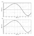
- the results of identifying the frequency characteristic Pc from the target column angular velocity ⁇ ref to the column angle ⁇ c on the simulation are the Bode diagrams of FIGS. 15A and 15B, and the inverse transfer function for this identification result, that is, FIG. 16 shows the equation 8 and the result of fitting to it.
- the thin line in FIG. 16 is the inverse transfer function, and the thick line is the fitting result.
- the fitted transfer function is a third-order filter expressed by Equation 9.
- the numerator coefficients b 3 to b 0 and the denominator coefficients a 3 to a 0 were obtained by repetitive calculations as filter coefficients having the same gain and phase with respect to the thin line in FIG.
- the fitting result is set as the transfer function Ch of the rudder angle disturbance compensation unit 144.
- the target steering torque generation unit is set only for the basic map, and the target steering torque is set to a straight line such that the target twist angle ⁇ ref is 5 [deg] with respect to 100 [deg] of the steering angle ⁇ h.
- the output D G of the damper gain map 123 and the output T ref — c of the hysteresis correction unit 124 are set to 0 [Nm].
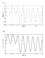
- FIG. 17 shows the time response of the steering angle ⁇ h as a steering input and disturbance. The frequency increases from 0 [sec] to 5 [sec], and the input is assumed to be rapid steering.
- FIG. 18 was used in both cases with and without rudder angle disturbance compensation, and the result in FIG. 18 was obtained.
- the target twist angle [deg] indicated by a thin line substantially overlaps the characteristic with compensation indicated by the broken line. It can be seen from FIG. 18 that the one with the steering angle disturbance compensation better follows the target twist angle. Also, in the case of sudden steering, the desired torsion angle is followed to achieve a desired steering torque.
- Damper gain map 123 of the vehicle speed sensitive target steering torque generator 120 is provided by compensating the target steering torque proportional to the steering angular velocity omega h, it can have a viscosity sense of feeling .
- the steering angle of the steering wheel is turned off, letting it go allows the steering wheel to oscillate without oscillation and improve system stability.
- a simulation was performed in which manual input from the upper side of the handle 1 was 3 [Nm] between 0 and 1 [sec] and 0 [Nm] after 1 [sec].
- 19 and 20 show simulation results. As shown in FIG. 19 (B), a state in which 3 [Nm] of manual input torque is applied up to 1 [sec] (the steering angle in FIG. 19 (A) is 30).
- the torsion angle control unit 140 inputs the column angle ⁇ c of the lower angle of the torsion bar and calculates and uses the steering angle ⁇ h, as in the configuration example shown in FIG. 21 (second embodiment). Also good. That is, the relationship among the torsion angle ⁇ , the steering angle ⁇ h, and the column angle ⁇ c is expressed by Equation 10.
- a configuration example (third to fifth embodiments) in which the torsion angle control unit includes a stabilization compensation unit will be described.
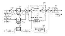
- FIG. 22 is a block diagram showing a configuration example (third embodiment) of a torsion angle control unit provided with a stabilization compensation unit for the motor angular velocity ⁇ m .
- a stabilization compensation unit 147 and an addition unit 148 are added, and the motor angular velocity ⁇ m is a stabilization compensation unit of the compensation value Cs (transfer function). 147, and the current command value Isb from the stabilization compensator 147 is input to the adder 148. If the gains of the torsion angle FB compensation unit 142 and the steering angle disturbance compensation unit 144 are increased in order to improve followability and disturbance characteristics, a high-frequency controllable oscillation phenomenon occurs.
- the transfer function (Cs) of the stabilization compensator 147 may be, for example, a second order filter or a fourth order filter.
- the current command value Is from the speed controller 130 and the current command value Isb from the stabilization compensator 147 are added by the adder 148, and the current command value Isa obtained by the addition is input to the limiter 146.
- Step S50A, S50B the operations of the stabilization compensator 147 and the addition unit 148 (see FIG. 23) Steps S50A, S50B) are added. That is, the current command value Is output from the adding unit 134 in the speed control unit 130 is input to the adding unit 148. Then, the motor angular velocity ⁇ m input to the reduction ratio unit 145 is also input to the stabilization compensator 147, and the stabilization compensation is performed by the stabilization compensator 147 (step S50A). The command value Isb is input to the adder 148.
- the adder 148 adds the current command values Is and Isb (step S50B), and the current command value Isa as the addition result is input to the limiter 146.
- Other operations are the same as those of the torsion angle control unit of the first embodiment.
- FIG. 24A shows the characteristics when the stabilization compensation unit 147 is not provided
- FIG. 24B shows the case where the stabilization compensation unit 147 is provided, and displays 0 [sec] to 1 [sec]. Yes.
- the thin line is the target twist angle ⁇ ref [deg]
- the thick line is the twist angle ⁇ [deg].
- the gain of the twist angle FB compensator 142 can be set large, and as a result, the followability to the target twist angle ⁇ ref [deg] can be enhanced.
- the primary filter of Formula 12 is set for the motor angular velocity ⁇ m by the setting of the stabilization compensator 147.
- FIG. 25 is a block diagram illustrating a configuration example (fourth embodiment) of a twist angle control unit provided with a stabilization compensator for the twist angle ⁇ .
- a twist angle control unit provided with a stabilization compensator for the twist angle ⁇ .
- the torsion angle control unit of the third embodiment shown in FIG. 22 not the motor angular velocity ⁇ m but the torsion angle ⁇ is input to the stabilization compensator 247.
- Other configurations are the same as those of the twist angle control unit of the third embodiment.
- the operation example of the torsion angle control unit of the fourth embodiment differs from the operation example of the torsion angle control unit of the third embodiment only in the operation of inputting the torsion angle ⁇ to the stabilization compensator 247. Are the same.
- FIG. 26 is a block diagram showing a configuration example (fifth embodiment) of a torsion angle controller provided with a stabilization compensator for the column angle ⁇ c.
- the stabilization angle compensation unit 347 is input with the column angle ⁇ c instead of the motor angular velocity ⁇ m .
- Other configurations are the same as those of the twist angle control unit of the third embodiment.
- the operation example of the torsion angle control unit of the fifth embodiment is different from the operation example of the torsion angle control unit of the third embodiment only in the operation of inputting the column angle ⁇ c to the stabilization compensator 247. Are the same.
- one stabilization compensation unit is used for each of the motor angular velocity ⁇ m , the torsion angle ⁇ , and the column angle ⁇ c.
- the stabilization compensation units are used in appropriate combinations. Also good.
- the basic map 121, the damper gain map 123, and the hysteresis correction unit 124 may be sensitive to the vehicle speed Vs, and a phase compensation unit is provided at the subsequent stage or the previous stage of the basic map 121. It may be inserted. For example, when it is desired to have a refreshing feeling with respect to steering, phase advance compensation may be set. Even if the current command value of the conventional assist control, the current command value of the estimated value of SAT (Self-Aligning Torque), or the current command value for suppressing the steering wheel vibration is added to the current command value I ref of the torsion angle control unit good.
- SAT Self-Aligning Torque
- the speed control unit is configured by IP control (proportional advance PI control), but PI control, P control, PID control, PI-D control, model matching control, model reference control Ordinarily used ones may be used.
- the steering angular velocity is obtained by differential calculation with respect to the steering angle ⁇ h, but an LPF (low-pass filter) process is appropriately performed in order to reduce the influence of high-frequency noise. Further, differential calculation and LPF processing may be performed by HPF (high pass filter) and gain. Further, the steering angular velocity, not the steering angle [theta] h, may be a signal subjected to processing of differential operation and LPF for detecting the angle theta 1 of the upper angle sensor.
- each of the above-described embodiments is a specific example for implementing the present invention (for example, sensor information or control amount such as target steering angle, actual steering angle, torsion bar torque, column angle, motor angular velocity, etc.)
- the technical scope of the present invention is not construed as being limited thereto.
- the present invention is applied to a column type EPS, but the present invention is not limited to an upstream type such as a column type, and can also be applied to a downstream type EPS such as a rack and pinion.
- the feedback control based on the target torsion angle is applicable to a steer-by-wire reaction force device that includes at least a torsion bar (an arbitrary spring constant) and a torsion angle detection sensor.
- a torsion bar an arbitrary spring constant
- a torsion angle detection sensor an arbitrary spring constant
- the figure used in description of the above-mentioned embodiment shows an example, and is not limited to these.
- the relational expression and the mathematical expression are not limited to the above, and may be any realizable expression.
Landscapes
- Engineering & Computer Science (AREA)
- Chemical & Material Sciences (AREA)
- Combustion & Propulsion (AREA)
- Transportation (AREA)
- Mechanical Engineering (AREA)
- Steering Control In Accordance With Driving Conditions (AREA)
- Power Steering Mechanism (AREA)
Abstract
【課題】路面の状態に影響されず、経年によるステアリング操舵系の機構特性の変化に左右されず、操舵角等の車両情報に対して同等の操舵トルクを容易に実現することが可能な電動パワーステアリング装置を提供する。 【解決手段】車両のハンドルのコラム軸にトーションバーを備え、コラム軸に接続されたモータを電流指令値に基づいて駆動制御することにより、操舵系をアシスト制御する電動パワーステアリング装置において、車両運転情報に基づいて目標操舵トルクを生成する目標操舵トルク生成部と、目標操舵トルクを目標捩れ角に変換する変換部と、目標捩れ角に対して、トーションバーの捩れ角を追従させるような電流指令値を算出する捩れ角制御部とを備え、トーションバーの検出トルクを車両運転情報に応じた値に追従するように制御する。
Description
本発明は、コラム軸(ステアリングシャフト、ハンドル軸)に備えられているトーションバーの捩れ角を、操舵角、車速、操舵状態等の車両運転情報に応じた値に追従するように制御することにより所望の操舵トルクを実現し、路面の状態に影響されず、経年による機構系特性の変化(摩擦、モータ出力特性など)に左右されない高性能な電動パワーステアリング装置に関する。
モータ制御装置を搭載した装置として電動パワーステアリング装置(EPS)があり、電動パワーステアリング装置は、車両の操舵系にモータの回転力でアシスト力(操舵補助力)を付与するものであり、インバータから供給される電力で制御されるモータの駆動力を、減速機構を含む伝達機構により、ステアリングシャフト或いはラック軸にアシスト力を付与する。かかる従来の電動パワーステアリング装置は、アシスト力を正確に発生させるため、モータ電流のフィードバック制御を行っている。フィードバック制御は、操舵補助指令値(電流指令値)とモータ電流検出値との差が小さくなるようにモータ印加電圧を調整するものであり、モータ印加電圧の調整は、一般的にPWM(パルス幅変調)制御のデューティの調整で行っている。
電動パワーステアリング装置の一般的な構成を図1に示して説明すると、ハンドル1のコラム軸(ステアリングシャフト、ハンドル軸)2は減速機構(ウォームとウォームホイールの噛み合い機構で減速比=1/N)3、ユニバーサルジョイント4a及び4b、ピニオンラック機構5、タイロッド6a,6bを経て、更にハブユニット7a,7bを介して操向車輪8L,8Rに連結されている。また、トーションバーを有するコラム軸2には、ハンドル1の操舵トルクTsを検出するトルクセンサ10及び操舵角θhを検出する舵角センサ14が設けられており、ハンドル1の操舵力を補助するモータ20が減速機構3を介してコラム軸2に連結されている。電動パワーステアリング装置を制御するコントロールユニット(ECU)30には、バッテリ13から電力が供給されると共に、イグニションキー11を経てイグニションキー信号が入力される。コントロールユニット30は、トルクセンサ10で検出された操舵トルクTsと車速センサ12で検出された車速Vsとに基づいてアシスト(操舵補助)指令の電流指令値の演算を行い、電流指令値に補償等を施した電圧制御指令値Vrefによって、EPS用モータ20に供給する電流を制御する。
コントロールユニット30には、車両の各種情報を授受するCAN(Controller Area Network)40が接続されており、車速VsはCAN40から受信することも可能である。また、コントロールユニット30には、CAN40以外の通信、アナログ/ディジタル信号、電波等を授受する非CAN41も接続可能である。
コントロールユニット30は主としてCPU(MCU、MPU等も含む)で構成されるが、そのCPU内部においてプログラムで実行される一般的な機能を示すと図2のようになる。
図2を参照してコントロールユニット30の機能及び動作を説明すると、トルクセンサ10で検出された操舵トルクTs及び車速センサ12で検出された(若しくはCAN40からの)車速Vsは、電流指令値Iref1を演算する電流指令値演算部31に入力される。電流指令値演算部31は、入力された操舵トルクTs及び車速Vsに基づいてアシストマップ等を用いて、モータ20に供給する電流の制御目標値である電流指令値Iref1を演算する。電流指令値Iref1は加算部32Aを経て電流制限部33に入力され、最大電流を制限された電流指令値Irefmが減算部32Bに入力され、フィードバックされているモータ電流値Imとの偏差I(=Irefm-Im)が演算され、その偏差Iが操舵動作の特性改善のためのPI(比例積分)制御部35に入力される。PI制御部35で特性改善された電圧制御指令値VrefがPWM制御部36に入力され、更に駆動部としてのインバータ37を介してモータ20がPWM駆動される。モータ20の電流値Imはモータ電流検出器38で検出され、減算部32Bにフィードバックされる。
加算部32Aには補償信号生成部34からの補償信号CMが加算されており、補償信号CMの加算によって操舵システム系の特性補償を行い、収れん性や慣性特性等を改善するようになっている。補償信号生成部34は、セルフアライニングトルク(SAT)34-3と慣性34-2を加算部34-4で加算し、その加算結果に更に収れん性34-1を加算部34-5で加算し、加算部34-5の加算結果を補償信号CMとしている。
このように従来のアシスト制御では、運転者の手入力にて加えた操舵トルク(トーションバーの捻れトルク)をトルクセンサで検出し、主にそのトルクに応じたアシスト電流としてモータ電流を制御している。しかしながら、この手法では、路面の状態(例えば傾斜)の違いにより、操舵角によって異なる操舵トルクとなってしまうことがある。また、モータ出力特性の経年製品によるバラツキにもより、異なる操舵特性になってしまう。
かかる問題を解決する車両制御装置として、例えば特許第5208894号公報(特許文献1)に示されるものがある。特許文献1の装置は、運転者の触覚特性に基づく適切な操舵トルクを与えることができるように、操舵角検出手段と、目標設定手段と、目標設定手段によって設定された操舵トルクの目標値が実現されるように制御する制御手段とを具備している。
しかしながら、特許文献1の装置では、操舵角と操舵トルクとの対応関係を、操舵角又は操舵トルクと手応え量との関係に基づいて予め求めておく必要があり、その対応関係から操舵角に対応する操舵トルクを目標値として設定しなければならない煩雑さがある。また、特許文献1の装置は、操舵トルクの目標値と検出される操舵トルクとの偏差に対してPI制御を用いている。
本発明は上述のような事情よりなされたものであり、本発明の目的は、路面の状態に影響されず、経年によるステアリング操舵系の機構特性の変化(摩擦、モータ出力特性など)に左右されず、操舵角等の車両運転情報に対して同等の操舵トルクを容易に実現することが可能な電動パワーステアリング装置を提供することにある。
本発明は車両のハンドルのコラム軸にトーションバーを備え、前記コラム軸に接続されたモータを電流指令値に基づいて駆動制御することにより、操舵系をアシスト制御する電動パワーステアリング装置に関し、本発明の上記目的は、車両運転情報に基づいて目標操舵トルクを生成する目標操舵トルク生成部と、目標トルクを目標捩れ角に変換する変換部と、前記目標捩れ角に対して、前記トーションバーの捩れ角を追従させるような前記電流指令値を算出する捩れ角制御部とを備え、前記トーションバーの検出トルクを前記車両運転情報に応じた値に追従するように制御することにより達成される。
また、本発明の上記目的は、前記捩れ角制御部が、前記目標捩れ角及び前記捩れ角の偏差に対して目標コラム角速度1を出力する捩れ角フィードバック補償部と、前記目標コラム角速度1に基づいて前記電流指令値を出力する速度制御部とで構成されていることにより、或いは、前記捩れ角制御部が更に、前記車両運転情報に対して目標コラム角速度2を出力する舵角外乱補償部と、前記モータ角速度をコラム角速度に変換する角速度変換部と、を備えることにより、或いは、前記捩れ角制御部では、前記速度制御部に前記目標コラム角速度1及び2の加算値である目標コラム角速度3と、前記コラム角速度とが入力され、前記目標コラム角速度3と前記コラム角速度の偏差を積分し、前記積分の積分値から前記目標コラム角速度の比例値を減算して前記電流指令値を出力するようになっていることにより、或いは、前記捩れ角制御部が更に、前記モータ角速度に対して伝達関数を設定してシステム全体の安定性を向上する安定化補償部を備えることにより、或いは、前記伝達関数が1次フィルタ若しくは2次フィルタであることにより、或いは、前記捩れ角制御部が更に、前記捩れ角に対して伝達関数を設定してシステム全体の安定性を向上する安定化補償部を備えることにより、或いは、前記捩れ角制御部が更に、コラム角に対して伝達関数を設定してシステム全体の安定性を向上する安定化補償部を備えることにより、或いは、前記伝達関数が2次フィルタ若しくは4次フィルタであることにより、或いは、前記目標操舵トルク生成部に前記ハンドルの右切り/左切りの操舵状態が入力されていることにより、或いは、前記目標操舵トルク生成部が、前記車両運転情報に応じて車速感応のトルク信号1を出力する基本マップと、前記車両運転情報の微分値に車速感応ダンパゲインを乗算してトルク信号2を出力するダンパゲイン部と、前記操舵状態に応じて前記車両運転情報をヒステリシス補正してトルク信号3を出力するヒステリシス補正部と、前記トルク信号1、並びに、前記トルク信号2及び前記トルク信号3のうち少なくとも1つの信号を加算して前記目標操舵トルクを出力する出力部と、で構成されていることにより、或いは、前記車速感応ダンパゲインが、車速に応じて徐々に大きくなる特性であることにより、或いは、前記ヒステリシス補正部が、関数を用いて前記車両運転情報をヒステリシス補正するようになっており、前記操舵状態が右切りの場合と左切りの場合とで前記関数を切り替え、前記関数の切り替え時には前記車両運転情報に対するオフセット調整値を更新することにより、或いは、前記オフセット調整値が、前記車両運転情報及び前記トルク信号3の前回値を用いて算出されることにより、或いは、前記速度制御部の後段に上下限値を制限するリミッタが設けられていることにより、或いは、前記捩れ角フィードバック補償部が伝達関数のゲイン値であることにより、或いは、前記舵角外乱補償部が、前記車両運転情報の変化による前記捩れ角への影響を抑制し、急操舵に対する目標捩れ角への前記捩れ角の追従性を向上する伝達関数の値であることにより、或いは、前記舵角外乱補償部の伝達関数の値が、前記操舵系及び車両系モデルの周波数伝達関数から定められることにより、或いは、前記車両運転情報が操舵角、車速、操舵状態であることにより、より効果的に達成される。
本発明の電動パワーステアリング装置によれば、ハンドルの右切り/左切りの操舵状態、車速及び操舵角等の車両運転情報から目標捩れ角を生成し、目標捩れ角と検出された捩れ角との偏差を適宜処理すること(例えば、偏差に補償値(伝達関数)を乗算した結果を目標コラム速度として、速度制御すること)で、目標捩れ角に捩れ角が追従するように動作し、操舵角等の車両運転情報に対して所望の操舵トルクを実現することができる。
更に、捩れ角制御に舵角外乱補償部を設けることにより、運転者から入力される操舵角の変化によるトーションバー捩れ角の影響を抑制し、急な操舵に対する目標捩れ角への捩れ角の追従性を一層向上することが可能である。
モータ角速度、捩れ角、又はコラム角に対し、安定化するために必要な伝達関数による安定化補償部を設けることにより、EPS制御システム全体の安定化を実現することも可能である。目標捩れ角へ捩れ角を追従させるために単純にゲインを上げると発振や振動が発生するが、安定化補償部による信号のフィードバックにより発振や振動を抑制できる。また、安定化補償部を設けることにより、高周波数帯域に発生する振動の発生を抑え、結果的に捩れ角フィードバック補償部のゲインを大きくし、指令値に対する追従性を向上することができる。
本発明は、路面の状態に影響されず、操舵角、車速、操舵状態等の車両運転情報に対して同等の操舵トルクを実現するための電動パワーステアリング装置であり、コラム軸に備えられているトーションバーの捩れ角を、車両運転情報に応じた値に追従するように制御することにより所望の操舵トルクを実現している。
以下に、本発明の実施の形態を、図面を参照して説明する。
図3は本発明の基本構成を示すブロック図であり、運転者のハンドル操舵はEPS操舵系/車両系100内のモータでアシスト制御される。操舵角θh等の車両運転情報に応じた目標操舵トルクTrefを出力する目標操舵トルク生成部120には、操舵の右切り又は左切りの操舵状態STs、車速Vs及び操舵角θhが入力され、目標操舵トルク生成部120で生成された目標操舵トルクTrefは、コラム軸2に設けられているトーションバー2Aのバネ定数をKtorとして、“1/Ktor”の特性を有する変換部101で目標捩れ角Δθrefに変換され、目標捩れ角Δθrefは捩れ角制御部140に入力される。捩れ角制御部140には目標捩れ角Δθref、操舵角θh、捩れ角Δθ及びモータ角速度ωmが入力されており、捩れ角制御部140で捩れ角Δθが目標捩れ角Δθrefとなるような電流指令値Irefが演算され、電流指令値IrefによりEPSのモータが駆動される。
EPS操舵系と各種センサの設置例は図4に示すようになっており、コラム軸2にはトーションバー2Aが備えられている。操向車輪8L,8Rには路面反力Fr及び路面情報μが作用し、トーションバー2Aを挟んでコラム軸2のハンドル側には上側角度センサ(角度θ1)が設けられ、トーションバー2Aを挟んでコラム軸2の操向車輪側には下側角度センサ(角度θ2)が設けられている。操舵角θhはコラム軸2の上部に設けられた舵角センサで検出され、上側角度センサの角度θ1及び下側角度センサの角度θ2の偏差から、下記数1及び数2によってトーションバー捩れ角Δθ及びトーションバートルクTtを求めることができる。なお、Ktorはトーションバー2Aのバネ定数である。
(数1)
θ1-θ2=Δθ
θ1-θ2=Δθ
(数2)
Ktor・Δθ=Ktor・(θ1-θ2)=Tt
なお、トーションバートルクTtは、例えば特開2008-216172号公報で示されるトルクセンサを用いて検出することができる。また、操舵の右切り又は左切りの操舵状態STsは、例えば図5に示すような操舵角θh及びモータ角速度ωmの関係で求めることができる。
Ktor・Δθ=Ktor・(θ1-θ2)=Tt
なお、トーションバートルクTtは、例えば特開2008-216172号公報で示されるトルクセンサを用いて検出することができる。また、操舵の右切り又は左切りの操舵状態STsは、例えば図5に示すような操舵角θh及びモータ角速度ωmの関係で求めることができる。
このような構成において、本発明の動作例を図6のフローチャートを参照して説明する。
先ず、操舵角θh、操舵状態STs、車速Vsが目標操舵トルク生成部120に入力され(ステップS1)、目標操舵トルク生成部120は目標操舵トルクTrefを生成する(ステップS10)。目標操舵トルクTrefは変換部101に入力され、変換部101で目標捩れ角Δθrefに変換される(ステップS30)。目標捩れ角Δθref、操舵角θh、捩れ角Δθ及びモータ角速度ωmが捩れ角制御部140に入力され(ステップS31)、捩れ角制御部140は捩れ角Δθが目標捩れ角Δθrefに追従するような電流指令値Irefを演算し(ステップS40)、電流指令値Irefに基づいてモータを駆動し、電流制御が実施される(ステップS60)。
なお、図6におけるデータの入力順番は適宜変更可能である。
図7は目標操舵トルク生成部120の構成例を示しており、操舵角θhは基本マップ121、微分部122及びヒステリシス補正部124に入力され、基本マップ121は、図8に示すような車速Vsをパラメータとするトルク信号Tref_aを出力する。図8では操舵角θhの絶対値|θh|でマップを構成しているが、正負の操舵角θhに応じてトルク信号Tref_aを出力するようにしても良い。トルク信号Tref_aは加算部126に入力される。
また、微分部122からは、操舵角θhを微分して得られる舵角速度ωhが出力され、舵角速度ωhは乗算部125に入力される。乗算部125には車速感応ダンパゲインDGが入力されており、乗算結果(=DG・ωh)であるトルク信号Tref_bは加算部127に入力される。車速感応ダンパゲインDGは車速感応のダンパゲインマップ123から車速Vsに応じて出力され、例えば図9に示すように車速Vsが高くなるに従って徐々に大きくなる特性である。なお、ダンパゲインマップ123及び乗算部125でダンパゲイン部を構成している。
右切り/左切り判定部110は例えば図5に示すような判定を行い、判定結果である操舵状態STsをヒステリシス補正部124に入力する。ヒステリシス補正部124には操舵角θhが入力されており、ヒステリシス補正部124は操舵角θh及び操舵状態STsに基づき、下記数3に従ってトルク信号Tref_cを演算する。ただし、x=θh、yR=Tref_c、yL=Tref_cとし、a>1、c>0である。


“a”として1より大きい任意の正数を用いることができ、例えば、ネイピア数“e”を用いた場合、数3及び数4は下記数5及び数6となる。


なお、右切り/左切り判定部110での判定方法は、図5に示されるような判定に限られない。例えば、操舵角θhの現在値が過去値に対してプラス方向(増分が0以上)に変化したか、又はマイナス方向(増分が0未満)に変化したかを確認し、その方向に基づいて判定しても良い。また、操舵角θhの代わりに、上側角度センサの角度θ1を用いても良い。
このような構成において、目標操舵トルク生成部120の動作例(図6のステップS10)を、図11のフローチャートを参照して説明する。
先ず、操舵角θh及び車速Vsが入力され(ステップS11)、基本マップ121は図8の特性に従い、操舵角θh及び車速Vsに応じたトルク信号Tref_aを生成して出力する(ステップS12)。操舵角θhは微分部122及びヒステリシス補正部124にも入力され、微分部122は操舵角θhを微分して舵角速度ωhを出力し(ステップS13)、ダンパゲインマップ123は車速Vsに応じた車速感応ダンパゲインDGを出力し(ステップS14)、乗算部125は舵角速度ωh及び車速感応ダンパゲインDGを乗算してトルク信号Tref_bを演算し、トルク信号Tref_bを加算部127に入力する(ステップS15)。
また、右切り/左切り判定部110は操舵の右切り/左切りを判定し、判定結果である操舵状態STsをヒステリシス補正部124に入力する(ステップS16)。ヒステリシス補正部124は操舵角θhに対して、且つ操舵状態STsに応じて数5及び数6の演算を行ってヒステリシス補正を実施し(ステップS17)、トルク信号Tref_cを生成する(ステップS18)。トルク信号Tref_cは加算部127に入力される。
上述のようにして得られたトルク信号Tref_a、トルク信号Tref_b、トルク信号Tref_cは出力部を構成する加算部126及び127で加算され、目標操舵トルクTrefが演算される(ステップS19)。即ち、トルク信号Tref_bとトルク信号Tref_cが加算部127で加算され、その加算結果にトルク信号Tref_aが加算部126で加算され、その加算結果が目標操舵トルクTrefとして出力される。
なお、図11のデータ入力及び演算等の順番は適宜変更可能である。
また、図12は捩れ角制御部140の構成例(第1実施形態)を示すブロック図であり、目標捩れ角Δθrefと捩れ角Δθの偏差Δθ0が減算部141で算出され、偏差Δθ0は補償値CFB(伝達関数)の捩れ角フィードバック(FB)補償部142に入力される。捩れ角FB補償部142は偏差Δθ0に対し補償値CFB(伝達関数)を乗算し、目標捩れ角Δθrefに捩れ角Δθが追従するような目標コラム角速度ωref1を出力する。目標コラム角速度ωref1は、加算部143に入力される。なお、補償値CFBは単純なゲインKppでも、或いはPI制御の補償値などでも良い。
操舵角θhは補償値Ch(伝達関数)の舵角外乱補償部144に入力され、操舵角θhに対して補償値Ch(伝達関数)を乗算し、目標コラム角速度ωref2を出力する。舵角外乱補償144によれば、運転者から入力される操舵角θhの変化による、トーションバー捩れ角Δθへの影響を抑制し、急操舵に対する目標捩れ角Δθrefへの捩れ角Δθの追従性を向上することができる。目標コラム角速度ωref1と目標コラム角速度ωref2は加算部143で加算され、目標コラム角速度ω refとなる。目標コラム角速度ω refは、I-P制御(比例先行型PI制御)の速度制御部130に入力される。運転者の操舵により操舵角θhが変化すると、それが外乱として捩れ角Δθに影響してしまい、目標捩れ角Δθrefに対してずれが発生する。特に急な操舵に対しては、それが顕著に出てしまう。舵角外乱補償部144の基本的な目的は、この外乱としての操舵角θhの影響を低減させることである。また、舵角外乱補償部144の伝達関数Chは、後述するプラントモデルの周波数伝達特性などから決定することにより、外乱の影響を抑制することが可能である。
I-P制御の速度制御部130は、目標コラム角速度ωrefにコラム角速度ωcが追従するような電流指令値Isを算出する。コラム角速度ωcは図12のように、モータ角速度ωmに減速機構である減速比部145の減速比“1/N”を乗算した値としても良い。速度制御部130からの電流指令値Isの上下限値を制限して、電流指令値Irefを出力するリミッタ146が速度制御部130の後段に設けられている。
このような構成において、捩れ角制御部140の動作例(図6のステップS40)を、図13のフローチャートを参照して説明する。
先ず目標捩れ角Δθref及び捩れ角Δθが入力され(ステップS41)、減算部141で偏差Δθ0が算出される(ステップS42)。偏差Δθ0は捩れ角FB補償部142に入力されて補償され(ステップS43)、補償された目標コラム角速度ωref1が加算部143に入力される。次いで操舵角θhが入力され(ステップS44)、操舵角θhは舵角外乱補償部144に入力されて補償され(ステップS45)、補償された目標コラム角速度ωref2が加算部143に入力される(ステップS46)。加算部143の加算結果である目標コラム角速度ωrefは、速度制御部130に入力される。
また、モータ角速度ωmは減速比部145で“1/N”を乗算され(ステップS47)、乗算結果であるコラム角速度ωcが速度制御部130に入力される(ステップS48)。目標コラム角速度ωrefとコラム角速度ωcの差分が減算部131で得られ、差分が積分部132で積分(Kvi/s)されて加算部134に入力される(ステップS50)。コラム角速度ωcは比例部133で比例処理(Kvp)され、比例結果が加算部134に入力され(ステップS50)、加算部134からの加算結果である電流指令値Isがリミッタ146で上下限値を制限され(ステップS51)、リミッタ146からモータ制御の電流指令値Irefが出力される(ステップS52)。
捩れ角制御部140は捩れ角FB補償部142と速度制御部130があれば、基本的には目標捩れ角Δθrefに捩れ角Δθを追従させ、所望の操舵トルクを実現することが可能である。
次に、舵角外乱補償部144の効果について説明する。
EPS操舵系/車両系100を図14のように速度制御部130込みとして扱った場合のシステム全体において、目標コラム角速度ωrefを入力とし、出力をコラム角θc及び捩れ角Δθとし、速度制御部130を含むシステム全体の伝達関数モデルをPcとする。捩れ角Δθは単純にコラム角θcと操舵角θhの差分(θc-θh)であり、減算部103で求められる。ただし、EPS操舵系/車両系100及び速度制御部130を含む伝達関数ブロック(Pω)102-1は、入力を目標コラム角速度ωref、出力をコラム角速度ωcとした伝達関数モデルであり、トーションバー2Aのバネ定数Ktor、コラム慣性などのEPS機構系特性と車両の動特性モデルも含む。また、伝達関数ブロック(Pω)102-1は、安定化補償部を含んでも良いし、含まなくても良い。コラム角速度ωcを、積分ブロック102-2で時間積分するとコラム角θcとなる。
図14を基に、捩れ角Δθを目標捩れ角Δθref、捩れ角FB補償部142の伝達関数CFB、舵角外乱補償部144の伝達関数Ch、システム全体の伝達関数Pcで表現すると、数7になる。
シミュレーション上で、目標コラム角速度ωrefからコラム角θcまでの周波数特性Pcを同定した結果は、図15(A)及び(B)のボード線図であり、更にこの同定結果に対する逆伝達関数、つまり数8とそれにフィッティングした結果を図16に示す。図16の細線が逆伝達関数であり、太線がフィッティング結果である。フィッティングした伝達関数は、数9で示される3次のフィルタとしている。分子の係数b3~b0と分母の係数a3~a0は、それぞれ図16の細線に対し、ゲインと位相が一致するようなフィルタの係数として、繰り返し計算により求めた。

次に、舵角外乱補償部144による効果を、シミュレーション結果を用いて説明する。目標操舵トルク生成部の設定は基本マップのみ行い、操舵角θhの100[deg]に対し、目標捩れ角Δθrefが5[deg]となるような目標操舵トルクの直線の設定とした。ダンパゲインマップ123の出力DG、ヒステリシス補正部124の出力Tref_cは0[Nm]としている。図17に、操舵入力及び外乱としての操舵角θhの時間応答を示す。0[sec]から5[sec]にかけて周波数が高くなり、急操舵を想定した入力としている。図17の操舵角θhを舵角外乱補償の有りと無しの両方の場合に用い、図18の結果を得た。なお、図18では見難いが、細線で示す目標捩れ角[deg]は破線の補償有りの特性とほぼ重なっている。図18より、舵角外乱補償が有る方が目標捩れ角へ良く追従しているのが分かる。また、急操舵の場合にも目標捩れ角へ追従し、所望の操舵トルクを実現している。
目標操舵トルク生成部120内に車速感応型のダンパゲインマップ123が設けられており、舵角速度ωhに比例した目標操舵トルクを補償することにより、フィーリングとしての粘性感を持たせることが出来る。ステアリングの舵角を切った状態から、手放しをすることにより、ハンドルが発振することなく収れん性を持たせ、システム安定性を向上させることができる。手放しを想定するために、ハンドル1の上側からの手入力を0~1[sec]の間で3[Nm]加え、1[sec]以降は0[Nm]としたシミュレーションを行った。図19及び図20はシミュレーション結果を示しており、図19(B)に示すように、1[sec]まで手入力トルクを3[Nm]加えた状態(図19(A)の舵角は30[deg]弱)から0[Nm]にステップ的に変化させることで手放しを想定しているが、図19(A)に示すように舵角が、0[deg]に安定して収束しているのが分かる。それに対し、ダンパゲインマップ123を設けない場合で、同じ手入力トルクを加えた応答は、図20に示すように振動的になり収束性が悪く、また、制御的に発振してしまう場合がある。
なお、捩れ角制御部140は、図21に示す構成例(第2実施形態)のように、トーションバーの下側角度のコラム角θcを入力し、操舵角θhを算出して用いるようにしても良い。即ち、捩れ角Δθ、操舵角θh及びコラム角θcの関係は、数10となる。
(数10)
Δθ=θc-θh
数10を操舵角θhについて変形すると、数11となる。
Δθ=θc-θh
数10を操舵角θhについて変形すると、数11となる。
(数11)
θh=θc-Δθ
よって、図21に示すように、捩れ角Δθ及びコラム角θcを減算部141Aに入力し、減算部141Aで数11を演算することによって操舵角θhを得ることができるので、この算出された操舵角θhを舵角外乱補償部144に入力することで、上述と同様な制御性能を達成できる。
θh=θc-Δθ
よって、図21に示すように、捩れ角Δθ及びコラム角θcを減算部141Aに入力し、減算部141Aで数11を演算することによって操舵角θhを得ることができるので、この算出された操舵角θhを舵角外乱補償部144に入力することで、上述と同様な制御性能を達成できる。
捩れ角制御部が安定化補償部を備える構成例(第3~第5実施形態)について説明する。システムの安定性を向上させる安定化補償部を設けることで、発振現象の対策を行うことができる。
図22は、モータ角速度ωmに対して安定化補償部を設けた捩れ角制御部の構成例(第3実施形態)を示すブロック図である。図12に示される第1実施形態の捩れ角制御部と比べると、安定化補償部147及び加算部148が追加されており、モータ角速度ωmは補償値Cs(伝達関数)の安定化補償部147に入力され、安定化補償部147からの電流指令値Isbが加算部148に入力される。追従性及び外乱特性を向上させるために、捩れ角FB補償部142、舵角外乱補償部144のゲインを上げると、高域の制御的な発振現象が発生してしまう。この対策として、モータ角速度ωmに対し、安定化するために必要な伝達関数(Cs)を安定化補償部147に設定する。これにより、EPS制御システム全体の安定化を実現することができる。安定化補償部147の伝達関数(Cs)として、例えば2次フィルタ、4次フィルタ等でも良い。
速度制御部130からの電流指令値Is及び安定化補償部147からの電流指令値Isbは加算部148で加算され、加算で得られた電流指令値Isaがリミッタ146に入力される。
第3実施形態の捩れ角制御部の動作例では、第1実施形態の捩れ角制御部の動作例に対して、図23に示されるように、安定化補償部147及び加算部148の動作(ステップS50A、S50B)が加わる。即ち、速度制御部130内の加算部134から出力された電流指令値Isは、加算部148に入力される。そして、減速比部145に入力されたモータ角速度ωmは安定化補償部147にも入力され、安定化補償部147で安定化補償が実施され(ステップS50A)、安定化補償部147からの電流指令値Isbは加算部148に入力される。加算部148で電流指令値Is及びIsbの加算が行われ(ステップS50B)、加算結果である電流指令値Isaはリミッタ146に入力される。その他の動作は、第1実施形態の捩れ角制御部の動作と同じである。
図17と同一の操舵角θhを入力した場合について、安定化補償部147の効果を示すシミュレーション結果を図24に示して説明する。安定化補償部147を設けない場合において、振動的になるように捩れ角FB補償部142のゲインを調整した。また、操舵角θhが増加する方向に操舵した場合、捩れ角Δθがプラスとなるように、符号を調整した。図24(A)が安定化補償部147が無い場合の特性であり、図24(B)が安定化補償部147を設けた場合であり、0[sec]から 1[sec]を表示している。安定化補償部147を設けることにより、高域の制御的な発振や振動を抑制していることが確認できる。図24ではほぼ重なっているが、細線が目標捩れ角Δθref[deg]であり、太線が捩れ角Δθ[deg]である。また、安定化補償部147を設けることにより、捩れ角FB補償部142のゲインを大きく設定することができ、結果的に目標捩れ角Δθref[deg]への追従性を高めることができる。本シミュレーションでは、安定化補償部147の設定で、モータ角速度ωmに対して数12の1次フィルタを設定した。

第4実施形態の捩れ角制御部の動作例は、第3実施形態の捩れ角制御部の動作例と比べると、安定化補償部247に捩れ角Δθが入力される動作が異なるだけで、その他は同じである。
第4実施形態における安定化補償部247の設定では、捩れ角Δθに対して数13の2次フィルタを設定することで、第3実施形態の場合とほぼ同等の効果が得られる。但し、第4実施形態でのシミュレーション結果例は割愛する。

第5実施形態の捩れ角制御部の動作例は、第3実施形態の捩れ角制御部の動作例と比べると、安定化補償部247にコラム角θcが入力される動作が異なるだけで、その他は同じである。
なお、第3~第5実施形態では、モータ角速度ωm、捩れ角Δθ及びコラム角θcそれぞれに対する安定化補償部を1つ使用しているが、各安定化補償部を適宜組み合わせて使用しても良い。
上述の実施形態(第1~第5実施形態)において、基本マップ121、ダンパゲインマップ123及びヒステリシス補正部124は車速Vsに感応したものでも良く、基本マップ121の後段若しくは前段に位相補償部を挿入してもよい。例えば操舵に対してスッキリ感を持たせたい場合は、位相進み補償を設定すれば良い。捩れ角制御部の電流指令値Irefに従来のアシスト制御の電流指令値、或いはSAT(Self-Aligning Torque)推定値の電流指令値、或いはハンドル振動抑制のための電流指令値を加算しても良い。
更に、上述の実施形態では速度制御部をI-P制御(比例先行型PI制御)で構成しているが、PI制御、P制御、PID制御、PI-D制御、モデルマッチング制御、モデル規範制御などの一般的に用いられるものでも良い。
また、上述の実施形態では、舵角速度は、操舵角θhに対する微分演算により求めているが、高域のノイズの影響を低減するために適度にLPF(ローパスフィルタ)処理を実施している。また、HPF(ハイパスフィルタ)とゲインにより、微分演算とLPFの処理を実施しても良い。更に、舵角速度は、操舵角θhではなく、上側角度センサの検出角度θ1に対する微分演算とLPFの処理を行った信号でも良い。
なお、上述の実施形態は、何れも本発明を実施するにあたっての具体化の例(例えば、目標操舵角、実舵角、トーションバートルク、コラム角、モータ角速度等のセンサ情報又は制御量等)を示したものに過ぎず、これらによって本発明の技術的範囲が限定的に解釈されるものではない。例えば、上述の実施形態では本発明をコラム型EPSに適用しているが、本発明はコラム型等の上流型に限られず、ラック&ピニオン等の下流型EPSにも適用可能である。更に、目標捩れ角に基づくフィードバック制御を行うということでは、トーションバー(バネ定数任意)及び捩れ角検出用のセンサを少なくとも備えるステアバイワイヤ反力装置等にも適用可能である。また、上述の実施形態の説明において使用した図は一例を示すものであり、これらに限られない。関係式や数式も上記に限られず、実現可能なものであれば良い。
1 ハンドル
2 コラム軸(ステアリングシャフト、ハンドル軸)
3 減速機構
10 トルクセンサ
12 車速センサ
14 舵角センサ
20 モータ
30 コントロールユニット(ECU)
100 EPS操舵系/車両系
101 変換部
110 右切り/左切り判定部
120 目標操舵トルク生成部
121 基本マップ
123 ダンパゲインマップ
124 ヒステリシス補正部
130 速度制御部
140 捩れ角制御部
142 捩れ角フィードバック(FB)補償部
144 舵角外乱補償部
147、247、347 安定化補償部
2 コラム軸(ステアリングシャフト、ハンドル軸)
3 減速機構
10 トルクセンサ
12 車速センサ
14 舵角センサ
20 モータ
30 コントロールユニット(ECU)
100 EPS操舵系/車両系
101 変換部
110 右切り/左切り判定部
120 目標操舵トルク生成部
121 基本マップ
123 ダンパゲインマップ
124 ヒステリシス補正部
130 速度制御部
140 捩れ角制御部
142 捩れ角フィードバック(FB)補償部
144 舵角外乱補償部
147、247、347 安定化補償部
Claims (19)
- 車両のハンドルのコラム軸にトーションバーを備え、前記コラム軸に接続されたモータを電流指令値に基づいて駆動制御することにより、操舵系をアシスト制御する電動パワーステアリング装置において、
車両運転情報に基づいて目標操舵トルクを生成する目標操舵トルク生成部と、
目標操舵トルクを目標捩れ角に変換する変換部と、
前記目標捩れ角に対して、前記トーションバーの捩れ角を追従させるような前記電流指令値を算出する捩れ角制御部と、
を備え、
前記トーションバーの検出トルクを前記車両運転情報に応じた値に追従するように制御することを特徴とする電動パワーステアリング装置。 - 前記捩れ角制御部が、
前記目標捩れ角及び前記捩れ角の偏差に対して目標コラム角速度1を出力する捩れ角フィードバック補償部と、
前記目標コラム角速度1に基づいて前記電流指令値を出力する速度制御部とで構成されている請求項1に記載の電動パワーステアリング装置。 - 前記捩れ角制御部が更に、
前記車両運転情報に対して目標コラム角速度2を出力する舵角外乱補償部と、
前記モータ角速度をコラム角速度に変換する角速度変換部と、
を備える請求項2に記載の電動パワーステアリング装置。 - 前記捩れ角制御部では、
前記速度制御部に前記目標コラム角速度1及び2の加算値である目標コラム角速度3と、前記コラム角速度とが入力され、前記目標コラム角速度3と前記コラム角速度の偏差を積分し、前記積分の積分値から前記目標コラム角速度の比例値を減算して前記電流指令値を出力するようになっている請求項3に記載の電動パワーステアリング装置。 - 前記捩れ角制御部が更に、
前記モータ角速度に対して伝達関数を設定してシステム全体の安定性を向上する安定化補償部を備える請求項3に記載の電動パワーステアリング装置。 - 前記伝達関数が1次フィルタ若しくは2次フィルタである請求項5に記載の電動パワーステアリング装置。
- 前記捩れ角制御部が更に、
前記捩れ角に対して伝達関数を設定してシステム全体の安定性を向上する安定化補償部を備える請求項3に記載の電動パワーステアリング装置。 - 前記捩れ角制御部が更に、
コラム角に対して伝達関数を設定してシステム全体の安定性を向上する安定化補償部を備える請求項3に記載の電動パワーステアリング装置。 - 前記伝達関数が2次フィルタ若しくは4次フィルタである請求項7又は8に記載の電動パワーステアリング装置。
- 前記目標操舵トルク生成部に前記ハンドルの右切り/左切りの操舵状態が入力されている請求項1乃至9のいずれかに記載の電動パワーステアリング装置。
- 前記目標操舵トルク生成部が、
前記車両運転情報に応じて車速感応のトルク信号1を出力する基本マップと、
前記車両運転情報の微分値に車速感応ダンパゲインを乗算してトルク信号2を出力するダンパゲイン部と、
前記操舵状態に応じて前記車両運転情報をヒステリシス補正してトルク信号3を出力するヒステリシス補正部と、
前記トルク信号1、並びに、前記トルク信号2及び前記トルク信号3のうち少なくとも1つの信号を加算して前記目標操舵トルクを出力する出力部と、
で構成されている請求項10に記載の電動パワーステアリング装置。 - 前記車速感応ダンパゲインが、車速に応じて徐々に大きくなる特性である請求項11に記載の電動パワーステアリング装置。
- 前記ヒステリシス補正部が、関数を用いて前記車両運転情報をヒステリシス補正するようになっており、前記操舵状態が右切りの場合と左切りの場合とで前記関数を切り替え、前記関数の切り替え時には前記車両運転情報に対するオフセット調整値を更新する請求項11又は12に記載の電動パワーステアリング装置。
- 前記オフセット調整値が、前記車両運転情報及び前記トルク信号3の前回値を用いて算出される請求項13に記載の電動パワーステアリング装置。
- 前記速度制御部の後段に上下限値を制限するリミッタが設けられている請求項2乃至14のいずれかに記載の電動パワーステアリング装置。
- 前記捩れ角フィードバック補償部が伝達関数のゲイン値である請求項2乃至15のいずれかに記載の電動パワーステアリング装置。
- 前記舵角外乱補償部が、前記車両運転情報の変化による前記捩れ角への影響を抑制し、急操舵に対する目標捩れ角への前記捩れ角の追従性を向上する伝達関数の値である請求項3乃至16のいずれかに記載の電動パワーステアリング装置。
- 前記舵角外乱補償部の伝達関数の値が、前記操舵系及び車両系モデルの周波数伝達関数から定められる請求項17に記載の電動パワーステアリング装置。
- 前記車両運転情報が操舵角、車速、操舵状態である請求項1乃至18のいずれかに記載の電動パワーステアリング装置。
Priority Applications (4)
| Application Number | Priority Date | Filing Date | Title |
|---|---|---|---|
| JP2018567490A JP6531876B2 (ja) | 2017-02-09 | 2018-02-08 | 電動パワーステアリング装置 |
| US16/341,100 US10562562B2 (en) | 2017-02-09 | 2018-02-08 | Electric power steering apparatus |
| EP18750785.0A EP3511227A4 (en) | 2017-02-09 | 2018-02-08 | POWER ASSISTED STEERING DEVICE |
| CN201880007688.2A CN110248860B (zh) | 2017-02-09 | 2018-02-08 | 电动助力转向装置 |
Applications Claiming Priority (8)
| Application Number | Priority Date | Filing Date | Title |
|---|---|---|---|
| JP2017022516 | 2017-02-09 | ||
| JP2017-022521 | 2017-02-09 | ||
| JP2017022521 | 2017-02-09 | ||
| JP2017-022516 | 2017-02-09 | ||
| JP2017023026 | 2017-02-10 | ||
| JP2017-023025 | 2017-02-10 | ||
| JP2017023025 | 2017-02-10 | ||
| JP2017-023026 | 2017-02-10 |
Publications (1)
| Publication Number | Publication Date |
|---|---|
| WO2018147371A1 true WO2018147371A1 (ja) | 2018-08-16 |
Family
ID=63107589
Family Applications (1)
| Application Number | Title | Priority Date | Filing Date |
|---|---|---|---|
| PCT/JP2018/004398 WO2018147371A1 (ja) | 2017-02-09 | 2018-02-08 | 電動パワーステアリング装置 |
Country Status (5)
| Country | Link |
|---|---|
| US (1) | US10562562B2 (ja) |
| EP (1) | EP3511227A4 (ja) |
| JP (1) | JP6531876B2 (ja) |
| CN (1) | CN110248860B (ja) |
| WO (1) | WO2018147371A1 (ja) |
Cited By (7)
| Publication number | Priority date | Publication date | Assignee | Title |
|---|---|---|---|---|
| WO2019193976A1 (ja) * | 2018-04-06 | 2019-10-10 | 日本精工株式会社 | 車両用操向装置 |
| WO2020100411A1 (ja) * | 2018-11-15 | 2020-05-22 | 日本精工株式会社 | 車両用操向装置 |
| WO2020115973A1 (ja) * | 2018-12-04 | 2020-06-11 | 日本精工株式会社 | 車両用操向装置 |
| WO2020145036A1 (ja) * | 2019-01-11 | 2020-07-16 | 日本精工株式会社 | 車両用操向装置 |
| JP2020185819A (ja) * | 2019-05-10 | 2020-11-19 | 日本精工株式会社 | 車両用操向装置 |
| JP2021142835A (ja) * | 2020-03-11 | 2021-09-24 | 株式会社ジェイテクト | 操舵制御装置 |
| CN114889688A (zh) * | 2022-05-12 | 2022-08-12 | 一汽奔腾轿车有限公司 | 一种基于汽车eps的转向阻尼控制方法 |
Families Citing this family (6)
| Publication number | Priority date | Publication date | Assignee | Title |
|---|---|---|---|---|
| JP6555446B2 (ja) * | 2017-03-16 | 2019-08-07 | 日本精工株式会社 | 電動パワーステアリング装置 |
| US20220289275A1 (en) * | 2019-08-09 | 2022-09-15 | Nidec Corporation | Control device, drive device, electric power steering device, and control method |
| DE102019133025A1 (de) * | 2019-12-04 | 2021-06-10 | Zf Automotive Germany Gmbh | Verfahren zur Positionsregelung für ein Lenksystem |
| DE102021202482B4 (de) * | 2021-03-15 | 2023-06-29 | Continental Automotive Technologies GmbH | Regelungseinrichtung und Verfahren zur Lenkwinkelregelung eines Fahrzeugs |
| US11685427B2 (en) | 2021-04-12 | 2023-06-27 | Toyota Material Handling, Inc. | Electric actuator steering system for forklifts |
| CN116888034A (zh) * | 2022-09-26 | 2023-10-13 | 宁德时代新能源科技股份有限公司 | 车辆的控制方法及相关装置 |
Citations (3)
| Publication number | Priority date | Publication date | Assignee | Title |
|---|---|---|---|---|
| JP2011131629A (ja) * | 2009-12-22 | 2011-07-07 | Jtekt Corp | 電動パワーステアリング装置 |
| JP2014031120A (ja) * | 2012-08-03 | 2014-02-20 | Honda Motor Co Ltd | 電動パワーステアリング装置 |
| WO2016072143A1 (ja) * | 2014-11-07 | 2016-05-12 | 日本精工株式会社 | 電動パワーステアリング装置 |
Family Cites Families (10)
| Publication number | Priority date | Publication date | Assignee | Title |
|---|---|---|---|---|
| JP5109342B2 (ja) * | 2006-11-15 | 2012-12-26 | 日本精工株式会社 | 電動パワーステアリング装置 |
| JP5130716B2 (ja) * | 2007-01-09 | 2013-01-30 | 株式会社ジェイテクト | モータ制御装置および電気式動力舵取装置 |
| JP5041139B2 (ja) | 2007-03-07 | 2012-10-03 | 日本精工株式会社 | トルクセンサ及び電動式パワーステアリング装置 |
| JP4518133B2 (ja) * | 2007-10-24 | 2010-08-04 | 株式会社デンソー | 電動パワーステアリング制御装置 |
| JP5171487B2 (ja) * | 2008-09-02 | 2013-03-27 | 本田技研工業株式会社 | ステアリング装置 |
| JP5208894B2 (ja) * | 2009-09-14 | 2013-06-12 | 株式会社豊田中央研究所 | 車両制御装置、操舵模擬装置、及びプログラム |
| JP2013043553A (ja) * | 2011-08-24 | 2013-03-04 | Nissan Motor Co Ltd | 操舵反力生成装置、車両及び操舵反力生成方法 |
| JP5942726B2 (ja) * | 2012-09-18 | 2016-06-29 | 株式会社ジェイテクト | 電動パワーステアリング装置 |
| CN104583056B (zh) * | 2013-03-08 | 2017-02-22 | 日本精工株式会社 | 电动助力转向装置 |
| JP6764561B2 (ja) * | 2016-06-07 | 2020-10-07 | 株式会社ジェイテクト | 車両用操舵装置 |
-
2018
- 2018-02-08 CN CN201880007688.2A patent/CN110248860B/zh not_active Expired - Fee Related
- 2018-02-08 US US16/341,100 patent/US10562562B2/en not_active Expired - Fee Related
- 2018-02-08 WO PCT/JP2018/004398 patent/WO2018147371A1/ja unknown
- 2018-02-08 JP JP2018567490A patent/JP6531876B2/ja not_active Expired - Fee Related
- 2018-02-08 EP EP18750785.0A patent/EP3511227A4/en not_active Withdrawn
Patent Citations (3)
| Publication number | Priority date | Publication date | Assignee | Title |
|---|---|---|---|---|
| JP2011131629A (ja) * | 2009-12-22 | 2011-07-07 | Jtekt Corp | 電動パワーステアリング装置 |
| JP2014031120A (ja) * | 2012-08-03 | 2014-02-20 | Honda Motor Co Ltd | 電動パワーステアリング装置 |
| WO2016072143A1 (ja) * | 2014-11-07 | 2016-05-12 | 日本精工株式会社 | 電動パワーステアリング装置 |
Non-Patent Citations (1)
| Title |
|---|
| See also references of EP3511227A4 * |
Cited By (14)
| Publication number | Priority date | Publication date | Assignee | Title |
|---|---|---|---|---|
| WO2019193976A1 (ja) * | 2018-04-06 | 2019-10-10 | 日本精工株式会社 | 車両用操向装置 |
| JPWO2020100411A1 (ja) * | 2018-11-15 | 2021-09-24 | 日本精工株式会社 | 車両用操向装置 |
| WO2020100411A1 (ja) * | 2018-11-15 | 2020-05-22 | 日本精工株式会社 | 車両用操向装置 |
| WO2020115973A1 (ja) * | 2018-12-04 | 2020-06-11 | 日本精工株式会社 | 車両用操向装置 |
| JPWO2020115973A1 (ja) * | 2018-12-04 | 2021-10-28 | 日本精工株式会社 | 車両用操向装置 |
| WO2020145036A1 (ja) * | 2019-01-11 | 2020-07-16 | 日本精工株式会社 | 車両用操向装置 |
| JPWO2020145036A1 (ja) * | 2019-01-11 | 2021-11-04 | 日本精工株式会社 | 車両用操向装置 |
| JP7211438B2 (ja) | 2019-01-11 | 2023-01-24 | 日本精工株式会社 | 車両用操向装置 |
| JP2020185819A (ja) * | 2019-05-10 | 2020-11-19 | 日本精工株式会社 | 車両用操向装置 |
| JP7199643B2 (ja) | 2019-05-10 | 2023-01-06 | 日本精工株式会社 | 車両用操向装置 |
| JP2021142835A (ja) * | 2020-03-11 | 2021-09-24 | 株式会社ジェイテクト | 操舵制御装置 |
| JP7338520B2 (ja) | 2020-03-11 | 2023-09-05 | 株式会社ジェイテクト | 操舵制御装置 |
| CN114889688A (zh) * | 2022-05-12 | 2022-08-12 | 一汽奔腾轿车有限公司 | 一种基于汽车eps的转向阻尼控制方法 |
| CN114889688B (zh) * | 2022-05-12 | 2023-10-20 | 一汽奔腾轿车有限公司 | 一种基于汽车eps的转向阻尼控制方法 |
Also Published As
| Publication number | Publication date |
|---|---|
| CN110248860B (zh) | 2021-11-23 |
| EP3511227A1 (en) | 2019-07-17 |
| JP6531876B2 (ja) | 2019-06-19 |
| US20190359248A1 (en) | 2019-11-28 |
| EP3511227A4 (en) | 2019-10-23 |
| US10562562B2 (en) | 2020-02-18 |
| CN110248860A (zh) | 2019-09-17 |
| JPWO2018147371A1 (ja) | 2019-03-28 |
Similar Documents
| Publication | Publication Date | Title |
|---|---|---|
| WO2018147371A1 (ja) | 電動パワーステアリング装置 | |
| JP6504322B2 (ja) | 電動パワーステアリング装置 | |
| JP6555446B2 (ja) | 電動パワーステアリング装置 | |
| WO2019193976A1 (ja) | 車両用操向装置 | |
| JP7211438B2 (ja) | 車両用操向装置 | |
| JP6702513B2 (ja) | 車両用操向装置 | |
| US10994776B1 (en) | Vehicle steering apparatus | |
| WO2017014228A1 (ja) | 電動パワーステアリング装置の制御装置 | |
| WO2020100411A1 (ja) | 車両用操向装置 | |
| WO2015122043A1 (ja) | 電動パワーステアリング装置 | |
| JP6628017B1 (ja) | 車両用操向装置 | |
| WO2020213285A1 (ja) | 車両用操向装置 | |
| JP7437603B2 (ja) | 車両用操向装置 | |
| JP2020185819A (ja) | 車両用操向装置 | |
| WO2020183838A1 (ja) | 車両用操向装置 |
Legal Events
| Date | Code | Title | Description |
|---|---|---|---|
| 121 | Ep: the epo has been informed by wipo that ep was designated in this application |
Ref document number: 18750785 Country of ref document: EP Kind code of ref document: A1 |
|
| ENP | Entry into the national phase |
Ref document number: 2018567490 Country of ref document: JP Kind code of ref document: A |
|
| ENP | Entry into the national phase |
Ref document number: 2018750785 Country of ref document: EP Effective date: 20190410 |
|
| NENP | Non-entry into the national phase |
Ref country code: DE |