WO2018142813A1 - Feuille adhésive contenant une couche à faible indice de réfraction, procédé de production d'une feuille adhésive contenant une couche à faible indice de réfraction et dispositif optique - Google Patents
Feuille adhésive contenant une couche à faible indice de réfraction, procédé de production d'une feuille adhésive contenant une couche à faible indice de réfraction et dispositif optique Download PDFInfo
- Publication number
- WO2018142813A1 WO2018142813A1 PCT/JP2017/046457 JP2017046457W WO2018142813A1 WO 2018142813 A1 WO2018142813 A1 WO 2018142813A1 JP 2017046457 W JP2017046457 W JP 2017046457W WO 2018142813 A1 WO2018142813 A1 WO 2018142813A1
- Authority
- WO
- WIPO (PCT)
- Prior art keywords
- gel
- refractive index
- low refractive
- layer
- index layer
- Prior art date
Links
Images


Classifications
-
- G—PHYSICS
- G02—OPTICS
- G02B—OPTICAL ELEMENTS, SYSTEMS OR APPARATUS
- G02B6/00—Light guides; Structural details of arrangements comprising light guides and other optical elements, e.g. couplings
- G02B6/0001—Light guides; Structural details of arrangements comprising light guides and other optical elements, e.g. couplings specially adapted for lighting devices or systems
- G02B6/0011—Light guides; Structural details of arrangements comprising light guides and other optical elements, e.g. couplings specially adapted for lighting devices or systems the light guides being planar or of plate-like form
- G02B6/0033—Means for improving the coupling-out of light from the light guide
- G02B6/005—Means for improving the coupling-out of light from the light guide provided by one optical element, or plurality thereof, placed on the light output side of the light guide
- G02B6/0055—Reflecting element, sheet or layer
-
- G—PHYSICS
- G02—OPTICS
- G02B—OPTICAL ELEMENTS, SYSTEMS OR APPARATUS
- G02B1/00—Optical elements characterised by the material of which they are made; Optical coatings for optical elements
- G02B1/10—Optical coatings produced by application to, or surface treatment of, optical elements
- G02B1/11—Anti-reflection coatings
- G02B1/111—Anti-reflection coatings using layers comprising organic materials
-
- C—CHEMISTRY; METALLURGY
- C09—DYES; PAINTS; POLISHES; NATURAL RESINS; ADHESIVES; COMPOSITIONS NOT OTHERWISE PROVIDED FOR; APPLICATIONS OF MATERIALS NOT OTHERWISE PROVIDED FOR
- C09J—ADHESIVES; NON-MECHANICAL ASPECTS OF ADHESIVE PROCESSES IN GENERAL; ADHESIVE PROCESSES NOT PROVIDED FOR ELSEWHERE; USE OF MATERIALS AS ADHESIVES
- C09J7/00—Adhesives in the form of films or foils
- C09J7/20—Adhesives in the form of films or foils characterised by their carriers
- C09J7/22—Plastics; Metallised plastics
- C09J7/26—Porous or cellular plastics
-
- G—PHYSICS
- G02—OPTICS
- G02B—OPTICAL ELEMENTS, SYSTEMS OR APPARATUS
- G02B6/00—Light guides; Structural details of arrangements comprising light guides and other optical elements, e.g. couplings
- G02B6/0001—Light guides; Structural details of arrangements comprising light guides and other optical elements, e.g. couplings specially adapted for lighting devices or systems
- G02B6/0011—Light guides; Structural details of arrangements comprising light guides and other optical elements, e.g. couplings specially adapted for lighting devices or systems the light guides being planar or of plate-like form
- G02B6/0065—Manufacturing aspects; Material aspects
-
- C—CHEMISTRY; METALLURGY
- C09—DYES; PAINTS; POLISHES; NATURAL RESINS; ADHESIVES; COMPOSITIONS NOT OTHERWISE PROVIDED FOR; APPLICATIONS OF MATERIALS NOT OTHERWISE PROVIDED FOR
- C09J—ADHESIVES; NON-MECHANICAL ASPECTS OF ADHESIVE PROCESSES IN GENERAL; ADHESIVE PROCESSES NOT PROVIDED FOR ELSEWHERE; USE OF MATERIALS AS ADHESIVES
- C09J2203/00—Applications of adhesives in processes or use of adhesives in the form of films or foils
- C09J2203/318—Applications of adhesives in processes or use of adhesives in the form of films or foils for the production of liquid crystal displays
-
- C—CHEMISTRY; METALLURGY
- C09—DYES; PAINTS; POLISHES; NATURAL RESINS; ADHESIVES; COMPOSITIONS NOT OTHERWISE PROVIDED FOR; APPLICATIONS OF MATERIALS NOT OTHERWISE PROVIDED FOR
- C09J—ADHESIVES; NON-MECHANICAL ASPECTS OF ADHESIVE PROCESSES IN GENERAL; ADHESIVE PROCESSES NOT PROVIDED FOR ELSEWHERE; USE OF MATERIALS AS ADHESIVES
- C09J2301/00—Additional features of adhesives in the form of films or foils
- C09J2301/10—Additional features of adhesives in the form of films or foils characterized by the structural features of the adhesive tape or sheet
- C09J2301/12—Additional features of adhesives in the form of films or foils characterized by the structural features of the adhesive tape or sheet by the arrangement of layers
- C09J2301/124—Additional features of adhesives in the form of films or foils characterized by the structural features of the adhesive tape or sheet by the arrangement of layers the adhesive layer being present on both sides of the carrier, e.g. double-sided adhesive tape
-
- C—CHEMISTRY; METALLURGY
- C09—DYES; PAINTS; POLISHES; NATURAL RESINS; ADHESIVES; COMPOSITIONS NOT OTHERWISE PROVIDED FOR; APPLICATIONS OF MATERIALS NOT OTHERWISE PROVIDED FOR
- C09J—ADHESIVES; NON-MECHANICAL ASPECTS OF ADHESIVE PROCESSES IN GENERAL; ADHESIVE PROCESSES NOT PROVIDED FOR ELSEWHERE; USE OF MATERIALS AS ADHESIVES
- C09J2301/00—Additional features of adhesives in the form of films or foils
- C09J2301/30—Additional features of adhesives in the form of films or foils characterized by the chemical, physicochemical or physical properties of the adhesive or the carrier
- C09J2301/302—Additional features of adhesives in the form of films or foils characterized by the chemical, physicochemical or physical properties of the adhesive or the carrier the adhesive being pressure-sensitive, i.e. tacky at temperatures inferior to 30°C
-
- C—CHEMISTRY; METALLURGY
- C09—DYES; PAINTS; POLISHES; NATURAL RESINS; ADHESIVES; COMPOSITIONS NOT OTHERWISE PROVIDED FOR; APPLICATIONS OF MATERIALS NOT OTHERWISE PROVIDED FOR
- C09J—ADHESIVES; NON-MECHANICAL ASPECTS OF ADHESIVE PROCESSES IN GENERAL; ADHESIVE PROCESSES NOT PROVIDED FOR ELSEWHERE; USE OF MATERIALS AS ADHESIVES
- C09J2301/00—Additional features of adhesives in the form of films or foils
- C09J2301/30—Additional features of adhesives in the form of films or foils characterized by the chemical, physicochemical or physical properties of the adhesive or the carrier
- C09J2301/312—Additional features of adhesives in the form of films or foils characterized by the chemical, physicochemical or physical properties of the adhesive or the carrier parameters being the characterizing feature
-
- C—CHEMISTRY; METALLURGY
- C09—DYES; PAINTS; POLISHES; NATURAL RESINS; ADHESIVES; COMPOSITIONS NOT OTHERWISE PROVIDED FOR; APPLICATIONS OF MATERIALS NOT OTHERWISE PROVIDED FOR
- C09J—ADHESIVES; NON-MECHANICAL ASPECTS OF ADHESIVE PROCESSES IN GENERAL; ADHESIVE PROCESSES NOT PROVIDED FOR ELSEWHERE; USE OF MATERIALS AS ADHESIVES
- C09J2483/00—Presence of polysiloxane
- C09J2483/006—Presence of polysiloxane in the substrate
-
- G—PHYSICS
- G02—OPTICS
- G02B—OPTICAL ELEMENTS, SYSTEMS OR APPARATUS
- G02B2207/00—Coding scheme for general features or characteristics of optical elements and systems of subclass G02B, but not including elements and systems which would be classified in G02B6/00 and subgroups
- G02B2207/107—Porous materials, e.g. for reducing the refractive index
-
- G—PHYSICS
- G02—OPTICS
- G02B—OPTICAL ELEMENTS, SYSTEMS OR APPARATUS
- G02B2207/00—Coding scheme for general features or characteristics of optical elements and systems of subclass G02B, but not including elements and systems which would be classified in G02B6/00 and subgroups
- G02B2207/109—Sols, gels, sol-gel materials
Definitions
- the present invention relates to a low refractive index layer-containing adhesive sheet, a method for producing a low refractive index layer-containing adhesive sheet, and an optical device.
- an air layer having a low refractive index is used as the total reflection layer.
- each optical film member for example, a light guide plate and a reflection plate
- the liquid crystal device is laminated via an air layer.
- problems such as deflection of the members may occur, particularly when the members are large.
- integration of each member is desired due to the trend of thinning devices. For this reason, integrating each member with an adhesive without going through an air layer is performed (for example, patent document 1).
- there is no air layer that plays the role of total reflection optical characteristics such as light leakage may be deteriorated.
- Patent Document 2 describes a structure in which a layer having a lower refractive index than the light guide plate is inserted between the light guide plate and the reflection plate.
- JP 2012-156082 A Japanese Patent Laid-Open No. 10-62626
- the low refractive index layer is formed on a substrate and used. For this reason, when arrange
- an object of the present invention is to provide a low-refractive index layer-containing adhesive sheet that is thin and has a low refractive index, a method for producing a low-refractive index layer-containing adhesive sheet, and an optical device.
- the low refractive index layer-containing adhesive sheet of the present invention comprises a first adhesive layer, a low refractive index layer, and a second adhesive layer laminated in the order described above.
- the refractive index of the low refractive index layer is 1.25 or less.
- the first low refractive index layer-containing adhesive sheet according to the present invention includes a low refractive index layer forming step of forming the low refractive index layer on a transfer resin film substrate, and the low refractive index layer. It is a manufacturing method of the low refractive index layer containing adhesive sheet of the present invention including a transfer process of transferring on the adhesive layer.
- the manufacturing method of the 2nd low refractive index layer containing adhesive sheet in this invention is a coating process which directly applies the coating liquid which is the raw material of the said low refractive index layer on the said adhesive layer, It is a manufacturing method of the low refractive index layer containing adhesive sheet
- the optical device of the present invention includes a low refractive index layer-containing adhesive sheet, a first optical functional layer, and a second optical functional layer, wherein the first optical functional layer is the first optical functional layer. Attached to the surface of the adhesive layer opposite to the low refractive index layer, and the second optical functional layer is applied to the surface of the second adhesive layer opposite to the low refractive index layer. It is characterized by.
- a low refractive index layer-containing adhesive sheet that is thin and has a low refractive index
- a method for producing a low refractive index layer-containing adhesive sheet and an optical device.
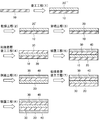
- FIG. 1 is a process cross-sectional view schematically showing an example of a method for producing a low refractive index layer and a method for producing a low refractive index layer-containing adhesive sheet according to the present invention.
- FIG. 2 is a diagram schematically showing a part of the steps of the method for producing a low refractive index layer and the method for producing an adhesive sheet containing a low refractive index layer of the present invention, and an example of an apparatus used therefor.
- FIG. 3 is a diagram schematically showing a part of the steps of the method for producing a low refractive index layer and the method for producing a low refractive index layer-containing adhesive sheet according to the present invention and another example of an apparatus used therefor.
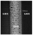
- FIG. 4 is a cross-sectional SEM image of the low refractive index layer-containing adhesive sheet of the example.
- the total thickness of the first adhesive layer and the second adhesive layer is the first adhesive layer, the low adhesive layer.
- the total thickness of the refractive index layer and the second adhesive layer may be 85% or more, 88% or more, 90% or more, or 92% or more, for example, 99.9% Hereinafter, it may be 99.5% or less, 99.3% or less, or 99.2% or less.
- the light transmittance of the laminate of the first adhesive layer, the low refractive index layer, and the second adhesive layer is 80%. It may be the above. Further, for example, the haze of the laminate of the first adhesive layer, the low refractive index layer, and the second adhesive layer may be 3% or less.
- the light transmittance may be, for example, 82% or more, 84% or more, 86% or more, or 88% or more, and the upper limit is not particularly limited, but is ideally 100%, for example, 95 % Or less, 92% or less, 91% or less, or 90% or less.
- the measurement of the haze of the laminate can be performed, for example, by the same method as the measurement of the haze of the low refractive index layer described later.
- the said light transmittance is the transmittance
- the low refractive index layer may be a void layer.
- the low refractive index layer-containing pressure-sensitive adhesive sheet of the present invention includes, for example, a separator on a surface opposite to the low refractive index layer in at least one of the first adhesive layer and the second adhesive layer. May be affixed.
- the method for producing the first low refractive index layer-containing adhesive sheet according to the present invention includes the low refractive index layer forming step of forming the low refractive index layer on the transfer resin film substrate, and the low refractive index layer forming step.
- a relatively small thickness is referred to as a “film” and a relatively large thickness is referred to as a “sheet”.
- film and “sheet” may be distinguished. There is no particular distinction.
- seat in this invention is the separator sticking process which attaches the said separator to the surface on the opposite side to the said low refractive index layer in the said adhesive layer further, for example. You may have.
- the manufacturing method of the 1st low refractive index layer containing adhesive sheet in this invention has the transfer resin film base material peeling process which peels the said transfer resin film base material after the said separator sticking process further, for example. It may be. In this case, it is preferable that the peeling force between the separator and the adhesive layer is greater than the peeling force between the transfer resin film substrate and the low refractive index layer.
- the transfer resin film substrate may be formed of an alicyclic structure-containing resin or an aliphatic structure-containing resin.
- an alicyclic structure-containing resin having excellent heat resistance from the viewpoint of durability against heat drying during formation of the low refractive index layer.
- said aliphatic structure containing resin For example, polyolefin, a polypropylene, polymethylpentene etc. are mentioned.
- the alicyclic structure-containing resin is not particularly limited, and examples thereof include polynorbornene and cyclic olefin copolymer.
- the optical device of the present invention is not particularly limited, and examples thereof include a liquid crystal display, an organic EL (Electro Luminescence) display, a micro LED (Light Emitting Diode) display, and an organic EL illumination.
- a liquid crystal display an organic EL (Electro Luminescence) display, a micro LED (Light Emitting Diode) display, and an organic EL illumination.
- an organic EL Electro Luminescence
- micro LED Light Emitting Diode
- the total thickness including the low refractive index layer greatly increases depending on the thickness of the substrate.
- the thickness of the device itself, in which thinning is important also increases.
- the low refractive index layer-containing pressure-sensitive adhesive sheet of the present invention can be reduced in thickness by not including, for example, a base material. Specifically, for example, by not including a substrate, there is almost no increase in thickness other than the thickness of the adhesive layer itself, and a low refractive index layer function can be introduced into the device. Moreover, since the adhesive layer is directly laminated on one or both sides of the low refractive index layer of the present invention, the adhesive layer containing the low refractive index layer of the present invention, the adhesive layer, The low refractive index layer is protected from physical damage. For this reason, the fragility of the low refractive index layer can be prevented from becoming a fatal problem.
- the adhesive layer can supplement the scratch resistance of the low refractive index layer, and can protect the low refractive index layer from scratches.
- the low refractive index layer containing adhesive sheet of this invention can be stuck to another member by the said adhesive layer, it is easy to introduce
- the manufacturing method of the low refractive index layer containing adhesive sheet of this invention is not specifically limited, For example, in the said manufacturing method of the 1st low refractive index layer containing adhesive sheet in this invention, or in the said this invention It can carry out by the manufacturing method of a 2nd low refractive index layer containing adhesive sheet. Hereinafter, an example will be described. In addition, in the following, the manufacturing method of the 1st low refractive index layer containing adhesive sheet in the said invention and the manufacturing method of the 2nd low refractive index layer containing adhesive sheet in this invention are put together.
- the low refractive index layer that is a component of the low refractive index layer-containing adhesive sheet of the present invention may be referred to as “low refractive index layer of the present invention”.
- the method for producing the low refractive index layer of the present invention may be referred to as “the method for producing the low refractive index layer of the present invention”.
- the low refractive index layer of the present invention may be formed of, for example, a silicon compound. Further, the low refractive index layer of the present invention may be, for example, a low refractive index layer formed by chemical bonding between microporous particles. For example, the fine pore particles may be a crushed gel.
- the gel pulverization step for pulverizing the gel of the porous body may be performed in one step, but is preferably performed in a plurality of pulverization steps.
- the number of pulverization stages is not particularly limited, and may be two stages or three or more stages, for example.
- the plurality of pulverization steps include a first pulverization step and a second pulverization step for pulverizing the gel
- the first pulverization step includes:
- the gel is pulverized into particles having a volume average particle size of 0.5 to 100 ⁇ m
- the second pulverization step further pulverizes the particles after the first pulverization step to obtain a volume average particle size. It may be a step of forming particles of 10 to 1000 nm.
- the plurality of pulverization stages may or may not include a pulverization stage other than the first pulverization stage and the second pulverization stage.
- the shape of the “particles” is not particularly limited, and may be, for example, spherical or non-spherical.
- the particles of the pulverized product may be, for example, sol-gel bead-like particles, nanoparticles (hollow nanosilica / nanoballoon particles), nanofibers, or the like.
- the gel is preferably a porous gel, and the pulverized product of the gel is preferably porous, but is not limited thereto.
- the gel pulverized product may have, for example, a structure having at least one of a particle shape, a fiber shape, and a flat plate shape.
- the particulate and flat structural units may be made of an inorganic substance, for example.
- the constituent element of the particulate structural unit may include at least one element selected from the group consisting of Si, Mg, Al, Ti, Zn, and Zr, for example.
- the structure (structural unit) that forms the particles may be a real particle or a hollow particle, and specifically includes silicone particles, silicone particles having fine pores, silica hollow nanoparticles, silica hollow nanoballoons, and the like.
- the fibrous structural unit is, for example, a nanofiber having a diameter of nanometer, and specifically includes cellulose nanofiber, alumina nanofiber, and the like.
- the plate-like structural unit include nanoclay, specifically, nano-sized bentonite (for example, Kunipia F [trade name]) and the like.
- the fibrous structural unit is not particularly limited, but for example, from the group consisting of carbon nanofiber, cellulose nanofiber, alumina nanofiber, chitin nanofiber, chitosan nanofiber, polymer nanofiber, glass nanofiber, and silica nanofiber. It may be at least one fibrous material selected.
- the gel pulverization step (for example, the plurality of pulverization steps, for example, the first pulverization step and the second pulverization step) may be performed by, for example, “others”. May be carried out in a "solvent”. The details of the “other solvent” will be described later.
- the “solvent” for example, a solvent for producing a gel, a solvent for producing a low refractive index layer, a solvent for substitution, etc.
- the “solvent” may not dissolve the gel or a pulverized product thereof.
- the pulverized product or the like may be dispersed or precipitated in the solvent.
- the volume average particle diameter of the gel after the first pulverization step may be, for example, 0.5 to 100 ⁇ m, 1 to 100 ⁇ m, 1 to 50 ⁇ m, 2 to 20 ⁇ m, or 3 to 10 ⁇ m.
- the volume average particle diameter of the gel after the second pulverization step may be, for example, 10 to 1000 nm, 100 to 500 nm, or 200 to 300 nm.
- the volume average particle diameter indicates the particle size variation of the pulverized product in the liquid containing the gel (gel-containing liquid).
- the volume average particle diameter is measured by, for example, a particle size distribution evaluation apparatus such as a dynamic light scattering method and a laser diffraction method, and an electron microscope such as a scanning electron microscope (SEM) and a transmission electron microscope (TEM). Can do.
- a particle size distribution evaluation apparatus such as a dynamic light scattering method and a laser diffraction method
- an electron microscope such as a scanning electron microscope (SEM) and a transmission electron microscope (TEM).
- the shear viscosity of the liquid immediately after the first pulverization step is, for example, 50 mPa / s or more, 1000 mPa ⁇ s or more, 2000 mPa ⁇ s or more, or 3000 mPa ⁇ s or more at a shear rate of 10001 / s.
- it may be 100 Pa ⁇ s or less, 50 Pa ⁇ s or less, or 10 Pa ⁇ s or less.
- the shear viscosity of the liquid immediately after the second pulverization step may be, for example, 1 mPa ⁇ s or more, 2 mPa ⁇ s or more, or 3 mPa ⁇ s or more, for example, 1000 mPa ⁇ s or less, 100 mPa ⁇ s or less, or It may be 50 mPa ⁇ s or less.
- the method for measuring the shear viscosity is not particularly limited. For example, as described in the examples below, the shear viscosity can be measured using a vibration type viscosity measuring machine (trade name FEM-1000V, manufactured by Seconic).
- the liquid containing the particles may have a shear viscosity of 50 mPa ⁇ s or more, and the particles may have a volume average particle diameter of 0.5 to 50 ⁇ m.
- the method for producing a low refractive index layer of the present invention preferably includes, for example, a concentration adjusting step for adjusting the concentration of the liquid containing the gel after the solvent replacement step and before the start of the first pulverization step. May be. In the case of including the concentration adjusting step, for example, it is preferable not to adjust the concentration of the liquid containing the gel after the start of the first pulverization stage.
- the gel concentration of the liquid containing the porous gel is, for example, 1% by weight or more, 1.5% by weight or more, 1.8% by weight or more, 2.0% by weight or more, or 2.8. It may be adjusted to not less than 5% by weight, for example, not more than 5% by weight, 4.5% by weight or less, 4.0% by weight or less, 3.8% by weight or less, or 3.4% by weight or less. good.
- the gel concentration of the liquid containing the gel is, for example, 1 to 5% by weight, 1.5 to 4.0% by weight, 2.0 to 3.8% by weight, or 2.8 to 3%. It may be adjusted to 4% by weight.
- the gel concentration is not too high so that the viscosity does not become too high. Further, from the viewpoint of use as a coating liquid described later, it is preferable that the gel concentration is not too low so that the viscosity does not become too low.
- the gel concentration of the liquid containing the gel is measured, for example, by measuring the weight of the liquid and the weight of the solid content (gel) after removing the solvent of the liquid, and dividing the measured value of the latter by the former measured value. Can be calculated.
- the concentration adjusting step for example, in order to appropriately adjust the gel concentration of the liquid containing the gel, the concentration may be decreased by adding a solvent, or the concentration may be increased by solvent volatilization.
- the concentration adjustment step for example, if the gel concentration of the liquid containing the gel is measured, if the gel concentration is appropriate, the concentration is not decreased or the concentration is not increased (concentration adjustment). Alternatively, it may be used for the next step as it is.
- the concentration adjusting step for example, if it is clear that the gel concentration of the liquid containing the gel is appropriate without measurement, the liquid containing the gel is not subjected to any measurement and concentration adjustment. You may use for the next process as it is.
- the change in the weight% concentration of the liquid containing the gel from immediately before the start of the first pulverization step to immediately after the end of the final pulverization step is, for example, within ⁇ 3%, within ⁇ 2.8%, ⁇ 2 It may be within 6%, within ⁇ 2.4%, or within ⁇ 2.2%.
- the method for producing a low refractive index layer of the present invention preferably further includes a gel form control step for controlling the shape and size of the gel prior to the solvent replacement step.
- a gel form control step it is preferable to control so that the size of the gel does not become too small. If the size of the gel is not too small, a large amount of solvent will adhere around the finely crushed gel, causing the measured value of the solvent concentration to be lower than the actual concentration or to remain higher than the actual concentration. This is because it is easy to prevent the problem that the measurement variation is large. Further, prior to the solvent replacement step, if the size of the gel is not too large, the solvent replacement efficiency is good. Moreover, it is preferable to control so that the size of each gel may become substantially uniform after the said gel form control process.
- the size of each gel is almost uniform, dispersion of gel pulverized product-containing liquid between each lot of gel pulverized product particle size, gel concentration and other variations can be suppressed, and the gel pulverized product-containing solution has excellent uniformity. It is because it is easy to obtain.
- the minor axis of the gel may be controlled to be, for example, 0.5 cm or more, 0.6 cm or more, 0.7 cm or more, or 0.8 cm or more, for example, 15 cm or less. , 13 cm or less, 10 cm or less, or 8 cm or less.
- the major axis of the gel may be controlled to be, for example, 30 cm or less, less than 30 cm, 28 cm or less, 25 cm or less, or 20 cm or less, for example, 1 cm or more, 2 cm or more, You may control so that it may become 3 cm or more, 4 cm or more, or 5 cm or more.
- the “minor axis” of a solid refers to a length measured at a position where the length is the shortest at a position where the length of the solid can be measured.
- the “major axis” of a solid refers to a length measured at a place where the length is the longest at a place where the length of the solid can be measured.
- the shape of the gel after the gel form control step is not particularly limited, and is, for example, a rectangular parallelepiped (including a cube), a cylindrical shape, a polygonal solid (for example, a polygonal column such as a triangular prism, a hexagonal column), a spherical shape, or What is necessary is just to control so that it may become an elliptical sphere (for example, shape like a rugby ball).
- the shape of the gel is controlled to be a rectangular parallelepiped or a substantially rectangular parallelepiped.
- the short side is controlled to be, for example, 0.5 cm or more, 0.6 cm or more, 0.7 cm or more, or 0.8 cm or more. For example, it may be controlled to be 15 cm or less, 13 cm or less, 10 cm or less, or 8 cm or less.
- the said gel form control process when controlling so that the said gel may become a rectangular parallelepiped, even if it controls so that a long side may be 30 cm or less, less than 30 cm, 28 cm or less, 25 cm or less, or 20 cm or less, for example.
- the “short side” of the rectangular parallelepiped refers to the shortest piece, and the “long side” refers to the longest piece.
- the gel form control step may be performed after the gel manufacturing step for manufacturing the gel, or may be performed during the gel manufacturing step (simultaneously with the gel manufacturing step). More specifically, for example, as follows.
- the gel may be controlled to the solid by cutting the gel in a state where the gel is fixed.
- the gel is extremely brittle, when the gel is cut, the gel may collapse unevenly regardless of the cutting direction. Therefore, by fixing the periphery of the gel, the pressure in the compression direction at the time of cutting is uniformly applied to the gel itself, so that the gel can be cut uniformly in the cutting direction.
- the shape of the gel before the solvent replacement step is substantially a rectangular parallelepiped, and in the gel shape control step, five of the six surfaces of the substantially rectangular parallelepiped gel surface are in contact with other substances.
- the gel may be cut by inserting a cutting jig into the gel from the exposed surface while the gel is fixed and the other surface is exposed.
- the cutting jig is not particularly limited, and examples thereof include a knife, a wire-like thin jig, and a thin and sharp plate-like jig. Moreover, you may perform the cutting
- the gel may be controlled to the solid by solidifying the gel raw material in a form (container) corresponding to the shape and size of the solid.
- a form corresponding to the shape and size of the solid.
- the gel concentration of the liquid containing the gel is measured, Only the liquid having a concentration within a predetermined numerical range may be subjected to the subsequent pulverization step.
- the gel concentration it is necessary to be a uniform liquid.
- the liquid is hard to separate to some extent with high viscosity after the pulverization step.
- the gel concentration is not too high because the viscosity does not become too high, and from the viewpoint of using as a coating liquid, the viscosity is not too low. It is preferred that the gel concentration is not too low. For example, from such a point of view, only the liquid having the gel concentration within a predetermined numerical range may be consistently provided until after the final pulverization stage.
- the predetermined numerical range of the gel concentration is, for example, as described above, and may be, for example, 2.8% by weight or more and 3.4% by weight or less, but is not limited thereto.
- the gel concentration measurement may be performed after the end of the first pulverization stage and before the end of the final pulverization stage, but in addition to or instead of this, the solvent substitution step It may be performed either before or after the gel pulverization step and after the final pulverization step (for example, the second pulverization step).
- concentration measurement for example, only the said liquid whose said gel density
- the concentration control after the solvent replacement step and before the gel grinding step the amount of solvent adhering to the gel is unstable, and thus there may be a large variation in each measurement of the concentration measurement value. Therefore, it is preferable to control the shape and size of the gel to be substantially uniform by the above-described gel form control step prior to the concentration management after the solvent replacement step and before the gel grinding step. Thereby, the concentration can be stably measured. Thereby, for example, it is possible to manage the gel concentration of the gel-containing liquid in a unified and accurate manner.
- the pulverization methods in the plurality of pulverization steps may all be different, but there may be a pulverization step performed by the same pulverization method.
- the plurality of pulverization stages are three stages, all three stages may be performed in different ways (that is, using three pulverization methods), and any two pulverization steps may be performed in the same pulverization method. It is also possible to carry out the other pulverization step in a different pulverization mode.
- the pulverization method is not particularly limited, and examples thereof include a cavitation method and a medialess method described later.
- the gel pulverized product-containing liquid is, for example, a sol liquid containing particles (pulverized product particles) obtained by pulverizing the gel.
- the plurality of pulverization steps include a coarse pulverization step and a main pulverization step, and after obtaining coarse sol particles by the coarse pulverization step, A sol particle maintaining a solid gel network may be obtained.
- the method for producing a low refractive index layer of the present invention for example, after at least one of the plurality of pulverization steps (for example, at least one of the first pulverization step and the second pulverization step), It further includes a classification step of classifying the particles.
- the method for producing a low refractive index layer of the present invention includes, for example, a gelation step in which a massive porous body is gelled in a solvent to form the gel.
- a gelation step in which a massive porous body is gelled in a solvent to form the gel.
- the gel gelled by the gelation process is used in the first pulverization stage (for example, the first pulverization stage) among the plurality of pulverization stages.
- the method for producing a low refractive index layer of the present invention includes, for example, an aging step of aging the gelled gel in a solvent.
- the gel after the aging step is used in the first pulverization step (for example, the first pulverization step) among the plurality of pulverization steps.
- the solvent replacement step of replacing the solvent with another solvent is performed.
- the gel in the other solvent is used in the first pulverization step (for example, the first pulverization step) among the plurality of pulverization steps.
- the shear viscosity of the liquid is controlled while measuring.
- At least one of the plurality of pulverization steps (for example, at least one of the first pulverization step and the second pulverization step) of the method for producing a low refractive index layer of the present invention is performed by, for example, high-pressure medialess pulverization. Do.
- the gel is, for example, a silicon compound gel containing at least a trifunctional or lower saturated bond functional group.
- the gel pulverized product-containing liquid obtained by the step including the gel pulverization step may be referred to as “the gel pulverized product-containing liquid of the present invention”.
- the present invention as a functional porous body is formed by forming the coating film and chemically bonding the pulverized products in the coating film.
- the low refractive index layer can be formed.
- the gel pulverized product-containing liquid of the present invention for example, the low refractive index layer of the present invention can be applied to various objects. Therefore, the gel pulverized product-containing liquid and the production method thereof of the present invention are useful, for example, in the production of the low refractive index layer of the present invention.
- the gel pulverized product-containing liquid of the present invention has, for example, extremely excellent uniformity, for example, when the low refractive index layer of the present invention is applied to uses such as optical members, the appearance is good. Can be.
- the gel pulverized product-containing liquid of the present invention is, for example, coated (coated) on the substrate and further dried. It may be a gel pulverized product-containing liquid. Moreover, the gel pulverized product-containing liquid of the present invention may be, for example, a gel pulverized product-containing liquid for obtaining a high porosity porous material (large thickness or massive bulk material). The bulk body can be obtained, for example, by performing bulk film formation using the gel pulverized product-containing liquid.
- the low refractive index layer of the present invention may be a void layer.
- the low refractive index layer of the present invention which is a void layer may be referred to as “the void layer of the present invention”.
- a step of producing the gel pulverized product-containing liquid of the present invention, a step of coating the gel pulverized product-containing liquid on a substrate to form a coating film, and a step of drying the coating film The void layer of the present invention having a high porosity can be produced by the production method including the above.
- the step of producing the gel crushed product-containing liquid of the present invention, the step of feeding out the roll-shaped resin film, and the coating of the gel crushed product-containing solution on the fed out resin film A process comprising a step of forming a film, a step of drying the coating film, and a step of winding the laminated film in which the low refractive index layer of the present invention is formed on the resin film after the drying step
- a laminated film roll can be produced by the method.
- such a production method may be referred to as a “production method of the laminated film roll of the present invention”.
- the laminated film roll manufactured by the manufacturing method of the laminated film roll of this invention may be called "the laminated film roll of this invention.”
- the gel pulverized product-containing liquid of the present invention includes, for example, a gel pulverized product pulverized by the gel pulverization step (for example, the first pulverization step and the second pulverization step) and the other solvent.
- the method for producing a low refractive index layer of the present invention may include, for example, a plurality of stages of gel crushing steps for crushing the gel (for example, porous gel) as described above. And the second pulverization step.
- the case where the method for producing a gel pulverized product-containing liquid of the present invention includes the first pulverization step and the second pulverization step will be mainly described as an example.
- the case where the said gel is a porous body (porous body gel) is mainly demonstrated.
- the present invention is not limited to this, and the description of the case where the gel is a porous body (porous body gel) can be applied by analogy other than the case where the gel is a porous body.
- the plurality of pulverization steps (for example, the first pulverization step and the second pulverization step) in the method for producing a low refractive index layer of the present invention may be collectively referred to as “gel pulverization step”.
- the gel pulverized product-containing liquid of the present invention can be used for the production of a functional porous body having the same function as the air layer (for example, low refractive index) as described later.
- the functional porous body may be, for example, the low refractive index layer of the present invention.
- the gel pulverized product-containing liquid obtained by the production method of the present invention contains the pulverized product of the porous gel, and the pulverized product has a three-dimensional structure of the unpulverized porous gel destroyed. , A new three-dimensional structure different from the uncrushed porous gel can be formed.
- a coating film (precursor of a functional porous body) formed using the gel pulverized material-containing liquid is not obtained in a layer formed using the unground porous gel. It becomes a layer in which a pore structure (new void structure) is formed. Thereby, the layer can exhibit the same function as the air layer (for example, the same low refractive index).
- the gel pulverized product-containing liquid of the present invention has a new three-dimensional structure formed as the coating film (precursor of a functional porous body), for example, because the pulverized product contains residual silanol groups. The pulverized product can be chemically bonded to each other.
- the formed functional porous body has a structure having voids, sufficient strength and flexibility can be maintained. For this reason, according to this invention, a functional porous body can be provided to various objects easily and simply.
- the gel pulverized product-containing liquid obtained by the production method of the present invention is very useful, for example, in the production of the porous structure that can be used as a substitute for the air layer.
- the air layer for example, it is necessary to form an air layer between the members by stacking the members with a gap provided therebetween via a spacer or the like.
- the functional porous body formed using the gel pulverized product-containing liquid of the present invention can exhibit the same function as the air layer only by placing it at a target site. Therefore, as described above, functions similar to the air layer can be imparted to various objects more easily and simply than forming the air layer.
- the gel pulverized product-containing liquid of the present invention can also be referred to as, for example, the functional porous body forming solution or the low refractive layer forming solution.
- the porous body is a pulverized product thereof.
- the range of the volume average particle diameter of the pulverized product (porous gel particles) is, for example, 10 to 1000 nm, 100 to 500 nm, and 200 to 300 nm.
- the said volume average particle diameter shows the particle size variation of the said ground material in the gel ground material containing liquid of this invention.
- the volume average particle diameter is, for example, a particle size distribution evaluation apparatus such as a dynamic light scattering method or a laser diffraction method, and an electron microscope such as a scanning electron microscope (SEM) or a transmission electron microscope (TEM). Can be measured.
- the gel concentration of the pulverized product is not particularly limited.
- particles having a particle size of 10 to 1000 nm are 2.5 to 4.5% by weight, 2.7 to 2.7%. It is 4.0% by weight and 2.8 to 3.2% by weight.
- the gel for example, porous gel
- examples thereof include a silicon compound.
- the silicon compound is not particularly limited, and examples thereof include a silicon compound containing at least a trifunctional or lower saturated bond functional group.
- the above-mentioned “including a saturated bond functional group having 3 or less functional groups” means that the silicon compound has 3 or less functional groups, and these functional groups are saturatedly bonded to silicon (Si). Means.
- the silicon compound is, for example, a compound represented by the following formula (2).
- R 1 and R 2 are each a linear or branched alkyl group, R 1 and R 2 may be the same or different, R 1 s may be the same as or different from each other when X is 2. R 2 may be the same as or different from each other.
- X and R 1 are, for example, the same as X and R 1 in the formula (1).
- R 2 is, for example, can be exemplified for R 1 is incorporated in the formula (1) described later.
- the silicon compound represented by the formula (2) include a compound represented by the following formula (2 ′) in which X is 3.
- R 1 and R 2 are the same as those in the formula (2), respectively.
- the silicon compound is trimethoxy (methyl) silane (hereinafter also referred to as “MTMS”).
- the concentration of the pulverized product of the porous gel in the solvent is not particularly limited, and is, for example, 0.3 to 50% (v / v), 0.5 to 30% ( v / v), 1.0 to 10% (v / v).
- concentration of the pulverized product is too high, for example, the fluidity of the gel pulverized product-containing liquid is remarkably lowered, and there is a possibility of generating aggregates and coating streaks during coating.
- the concentration of the pulverized product is too low, for example, not only does it take a considerable time to dry the solvent, but also the residual solvent immediately after drying increases, so the porosity may decrease. .
- the physical properties of the gel pulverized product-containing liquid of the present invention are not particularly limited.
- the shear viscosity of the gel pulverized product-containing liquid is, for example, 1 mPa ⁇ s to 1 Pa ⁇ s, 1 mPa ⁇ s to 500 mPa ⁇ s, 1 mPa ⁇ s to 50 mPa ⁇ s, 1 mPa ⁇ s at a shear rate of 10001 / s.
- shear viscosity is too high, for example, coating streaks may occur, and defects such as a decrease in the transfer rate of gravure coating may be observed.
- shear viscosity is too low, for example, the wet coating thickness at the time of coating cannot be increased, and a desired thickness may not be obtained after drying.
- examples of the solvent include a dispersion medium.
- the dispersion medium (hereinafter also referred to as “coating solvent”) is not particularly limited, and examples thereof include a gelling solvent and a grinding solvent described later, and the grinding solvent is preferable.
- the coating solvent includes an organic solvent having a boiling point of 70 ° C. or higher and lower than 180 ° C. and a saturated vapor pressure at 20 ° C. of 15 kPa or lower.
- organic solvent examples include carbon tetrachloride, 1,2-dichloroethane, 1,1,2,2-tetrachloroethane, trichloroethylene, isobutyl alcohol, isopropyl alcohol, isopentyl alcohol, 1-pentyl alcohol (pentanol), Ethyl alcohol (ethanol), ethylene glycol monoethyl ether, ethylene glycol monoethyl ether acetate, ethylene glycol mono-normal-butyl ether, ethylene glycol monomethyl ether, xylene, cresol, chlorobenzene, isobutyl acetate, isopropyl acetate, isopentyl acetate, ethyl acetate, Normal-butyl acetate, normal-propyl acetate, normal-pentyl acetate, cyclohexanol, cyclohexanone, 1,4-dioxa , N, N-dimethylformamide, s
- the gel pulverized material-containing liquid of the present invention includes, for example, a sol particle liquid that is the sol-like pulverized material dispersed in the dispersion medium.
- the gel pulverized product-containing liquid of the present invention for example, continuously forms a void layer having a film strength of a certain level or more by performing chemical crosslinking by a bonding step described later after coating and drying on a substrate.
- “sol” means that a three-dimensional structure of a gel is pulverized so that a pulverized product (that is, a nano-three-dimensional porous sol particle retaining a part of a void structure) is dissolved in a solvent. The state which disperse
- the gel pulverized product-containing liquid of the present invention may contain, for example, a catalyst for chemically bonding the gel pulverized products.
- the content of the catalyst is not particularly limited, and is, for example, 0.01 to 20% by weight, 0.05 to 10% by weight, or 0.1 to 5% by weight with respect to the weight of the pulverized product of the gel. .
- the gel pulverized product-containing liquid of the present invention may further contain, for example, a crosslinking aid for indirectly bonding the gel pulverized products.
- a crosslinking aid for indirectly bonding the gel pulverized products.
- the content of the crosslinking aid is not particularly limited.
- the content is 0.01 to 20% by weight, 0.05 to 15% by weight, or 0.1 to 10% by weight with respect to the weight of the pulverized gel. It is.
- the proportion of functional groups that do not contribute to the intra-gel cross-linking structure among the functional groups of the constituent monomer of the gel is, for example, 30 mol% or less, 25 mol% or less, 20 mol. % Or less, 15 mol% or less, for example, 1 mol% or more, 2 mol% or more, 3 mol% or more, 4 mol% or more may be sufficient.
- the ratio of the functional group that does not contribute to the in-gel crosslinked structure can be measured, for example, as follows.
- the mixing step is a step of mixing the porous gel particles (pulverized product) and the solvent, and may or may not be performed.
- the mixing step for example, there is a step of mixing a pulverized product of a gel-like silicon compound (silicon compound gel) obtained from a silicon compound containing at least a trifunctional or lower saturated bond functional group and a dispersion medium.
- the pulverized product of the porous gel can be obtained from the porous gel by a gel pulverization step described later.
- the pulverized product of the porous gel can be obtained, for example, from the porous gel after the aging treatment in which the aging step described later is performed.
- the gelation step is, for example, a step of gelling a massive porous body in a solvent to form the porous body gel.
- the gelation step is a step of producing a silicon compound gel by gelling a silicon compound containing at least a trifunctional or lower functional saturated bond functional group in a solvent.
- the gelation step will be described by taking the case where the porous body is a silicon compound as an example.
- the gelation step is, for example, a step of gelling the monomer silicon compound by a dehydration condensation reaction in the presence of a dehydration condensation catalyst, whereby a silicon compound gel is obtained.
- the silicon compound gel has, for example, residual silanol groups, and the residual silanol groups are preferably adjusted as appropriate according to chemical bonding between the pulverized products of the silicon compound gel described later.
- the silicon compound is not particularly limited as long as it is gelled by a dehydration condensation reaction.
- the silicon compounds are bonded.
- the bond between the silicon compounds is, for example, a hydrogen bond or an intermolecular force bond.
- Examples of the silicon compound include a silicon compound represented by the following formula (1). Since the silicon compound of the formula (1) has a hydroxyl group, the silicon compound of the formula (1) can be hydrogen bonded or intermolecularly bonded through, for example, each hydroxyl group.
- X is 2, 3 or 4
- R 1 is a linear or branched alkyl group.
- the carbon number of R 1 is, for example, 1-6, 1-4, 1-2.
- Examples of the linear alkyl group include a methyl group, an ethyl group, a propyl group, a butyl group, a pentyl group, and a hexyl group.
- Examples of the branched alkyl group include an isopropyl group and an isobutyl group.
- X is, for example, 3 or 4.
- the silicon compound represented by the formula (1) include a compound represented by the following formula (1 ′) in which X is 3.
- R 1 is the same as in the above formula (1), and is, for example, a methyl group.
- the silicon compound is tris (hydroxy) methylsilane.
- X is 3, the silicon compound is, for example, a trifunctional silane having three functional groups.
- silicon compound represented by the formula (1) examples include a compound in which X is 4.
- the silicon compound is, for example, a tetrafunctional silane having four functional groups.
- the silicon compound may be, for example, a precursor that forms the silicon compound of the formula (1) by hydrolysis.
- the precursor is not particularly limited as long as it can generate the silicon compound by hydrolysis, and specific examples thereof include a compound represented by the formula (2).
- the production method of the present invention may include, for example, a step of hydrolyzing the precursor prior to the gelation step.
- the hydrolysis method is not particularly limited, and can be performed, for example, by a chemical reaction in the presence of a catalyst.
- the catalyst include acids such as oxalic acid and acetic acid.
- the hydrolysis reaction can be performed, for example, by slowly dropping an aqueous solution of oxalic acid into the dimethyl sulfoxide solution of the silicon compound precursor in a room temperature environment and then stirring the mixture for about 30 minutes.
- hydrolyzing the silicon compound precursor for example, by completely hydrolyzing the alkoxy group of the silicon compound precursor, further heating and immobilization after gelation / aging / void structure formation, It can be expressed efficiently.
- examples of the silicon compound include a hydrolyzate of trimethoxy (methyl) silane.
- the silicon compound of the monomer is not particularly limited, and can be appropriately selected according to the use of the functional porous body to be produced, for example.
- the silicon compound is preferably the trifunctional silane from the viewpoint of excellent low refractive index property, and also has strength (for example, scratch resistance).
- the tetrafunctional silane is preferable from the viewpoint of excellent scratch resistance.
- the said silicon compound used as the raw material of the said silicon compound gel may use only 1 type, for example, and may use 2 or more types together.
- the silicon compound may include, for example, only the trifunctional silane, may include only the tetrafunctional silane, may include both the trifunctional silane and the tetrafunctional silane, Furthermore, other silicon compounds may be included.
- the ratio is not particularly limited and can be set as appropriate.
- the gelation of the porous body such as the silicon compound can be performed, for example, by a dehydration condensation reaction between the porous bodies.
- the dehydration condensation reaction is preferably performed, for example, in the presence of a catalyst.
- the catalyst include acid catalysts such as hydrochloric acid, oxalic acid, and sulfuric acid, and ammonia, potassium hydroxide, sodium hydroxide, ammonium hydroxide, and the like.
- a dehydration condensation catalyst such as a base catalyst.
- the dehydration condensation catalyst may be an acid catalyst or a base catalyst, but a base catalyst is preferred.
- the amount of the catalyst added to the porous body is not particularly limited, and for example, 0.01 to 10 mol, 0.05 to 7 mol, 0.1 to 5 moles.
- the gelation of the porous body such as the silicon compound is preferably performed in a solvent, for example.
- the ratio of the porous body in the solvent is not particularly limited.
- the solvent include dimethyl sulfoxide (DMSO), N-methylpyrrolidone (NMP), N, N-dimethylacetamide (DMAc), dimethylformamide (DMF), ⁇ -butyllactone (GBL), acetonitrile (MeCN), ethylene Examples thereof include glycol ethyl ether (EGEE).
- DMSO dimethyl sulfoxide
- NMP N-methylpyrrolidone
- DMAc N, N-dimethylacetamide
- DMF dimethylformamide
- GBL ⁇ -butyllactone
- MeCN acetonitrile
- ethylene examples thereof include glycol ethyl ether (EGEE).
- one type of solvent may be used, or two or more types may be used in combination.
- the solvent used for the gelation is
- the gelation conditions are not particularly limited.
- the treatment temperature for the solvent containing the porous body is, for example, 20 to 30 ° C., 22 to 28 ° C., 24 to 26 ° C., and the treatment time is, for example, 1 to 60 minutes, 5 to 40 minutes, 10 to 30 Minutes.
- the process conditions in particular are not restrict
- the gel form of the porous body obtained in the gelation step is not particularly limited.
- “Gel” generally refers to a solidified state in which a solute has a structure in which it loses independent motility due to interaction and aggregates.
- a wet gel includes a dispersion medium and a solute has a uniform structure in the dispersion medium.
- a xerogel is a network structure in which the solvent is removed and the solute has voids.
- the silicon compound gel is preferably a wet gel, for example.
- the remaining silanol group of the silicon compound gel is not particularly limited, and examples thereof include the ranges described later.
- the porous gel obtained by the gelation may be subjected, for example, to the solvent replacement step and the first pulverization step as it is, but prior to the first pulverization step, an aging treatment is performed in the aging step. You may give it.
- the gelled porous body (porous gel) is aged in a solvent.
- conditions for the aging treatment are not particularly limited, and for example, the porous gel may be incubated in a solvent at a predetermined temperature. According to the aging treatment, for example, the porous particles having a three-dimensional structure obtained by gelation can further grow the primary particles, thereby increasing the size of the particles themselves. is there.
- the contact state of the neck portion where the particles are in contact can be increased from point contact to surface contact, for example.
- the porous gel subjected to the aging treatment as described above, for example, increases the strength of the gel itself, and as a result, the strength of the three-dimensional basic structure of the pulverized product after pulverization can be further improved.
- the pore size of the void structure in which the three-dimensional basic structure is deposited It can suppress shrinking
- the lower limit of the temperature of the aging treatment is, for example, 30 ° C. or more, 35 ° C. or more, 40 ° C. or more, and the upper limit thereof is, for example, 80 ° C. or less, 75 ° C. or less, 70 ° C. or less.
- the predetermined time is not particularly limited, and the lower limit thereof is, for example, 5 hours or more, 10 hours or more, 15 hours or more, and the upper limit thereof is, for example, 50 hours or less, 40 hours or less, 30 hours or less.
- the range is, for example, 5 to 50 hours, 10 to 40 hours, 15 to 30 hours.
- the optimum conditions for aging are preferably set, for example, as described above, so that an increase in the size of the primary particles and an increase in the contact area of the neck portion can be obtained in the porous gel.
- the temperature of the aging treatment preferably takes into account, for example, the boiling point of the solvent used.
- the aging treatment for example, if the aging temperature is too high, the solvent is excessively volatilized, and there is a possibility that problems such as closing of the pores of the three-dimensional void structure occur due to the concentration of the coating solution. is there.
- the aging treatment for example, if the aging temperature is too low, the effect due to the aging is not sufficiently obtained, temperature variation with time of the mass production process increases, and a product with poor quality may be produced. There is.
- the same solvent as in the gelation step can be used, and specifically, the reaction product after the gel treatment (that is, the solvent containing the porous gel) may be applied as it is. preferable.
- the porous gel is the silicon compound gel
- the number of moles of residual silanol groups contained in the silicon compound gel after the aging treatment after gelation is, for example, the raw material used for the gelation (for example, the above-mentioned Silicon compound or precursor thereof) is the ratio of residual silanol groups when the number of moles of alkoxy groups is 100, and the lower limit is, for example, 50% or more, 40% or more, 30% or more, and the upper limit is For example, it is 1% or less, 3% or less, 5% or less, and the range is, for example, 1 to 50%, 3 to 40%, or 5 to 30%.
- the lower the number of moles of residual silanol groups For the purpose of increasing the hardness of the silicon compound gel, for example, the lower the number of moles of residual silanol groups, the better.
- the number of residual silanol groups is too high, for example, in the formation of the functional porous body, there is a possibility that the void structure cannot be maintained before the functional porous body precursor is crosslinked.
- the number of moles of residual silanol groups is too low, for example, in the bonding step, the precursor of the functional porous body cannot be crosslinked, and sufficient film strength may not be imparted.
- the above is an example of residual silanol groups.
- the silicon compound modified with various reactive functional groups as a raw material of the silicon compound gel, The same phenomenon can be applied.
- the porous gel obtained by the gelation is subjected to, for example, a aging treatment in the aging step, a solvent replacement step, and then subjected to the gel pulverization step.
- the solvent replacement step the solvent is replaced with another solvent.
- the gel crushing step is a step of crushing the porous gel as described above.
- the pulverization may be performed, for example, on the porous gel after the gelation step, or may be performed on the post-ripening porous gel that has been subjected to the aging treatment.
- a gel form control step for controlling the shape and size of the gel may be performed prior to the solvent replacement step (for example, after the aging step).
- the shape and size of the gel controlled in the gel form control step are not particularly limited, but are as described above, for example.
- the gel form control step may be performed, for example, by dividing (for example, cutting) the gel into a solid (three-dimensional body) having an appropriate size and shape.
- the gel pulverization step is performed after the solvent substitution step is performed on the gel.
- the solvent replacement step the solvent is replaced with another solvent. If the solvent is not replaced with the other solvent, for example, the catalyst and the solvent used in the gelation step remain after the aging step, and further gelation occurs over time, resulting in gel pulverization finally obtained This is because the pot life of the product-containing liquid may be affected, and the drying efficiency when the coating film formed using the gel pulverized product-containing liquid is dried may be decreased.
- the other solvent in the gel pulverization step is also referred to as a “grinding solvent”.
- the solvent for pulverization is not particularly limited, and for example, an organic solvent can be used.
- the organic solvent include solvents having a boiling point of 140 ° C. or lower, 130 ° C. or lower, a boiling point of 100 ° C. or lower, and a boiling point of 85 ° C. or lower. Specific examples include isopropyl alcohol (IPA), ethanol, methanol, n-butanol, 2-butanol, isobutyl alcohol, pentyl alcohol, propylene glycol monomethyl ether (PGME), methyl cellosolve, acetone and the like.
- the pulverizing solvent may be, for example, one type or a combination of two or more types.
- the solvent replacement step is divided into a plurality of solvent replacement steps.
- the step performed later is more than the step performed earlier.
- the hydrophilicity of the other solvent may be lowered.
- the solvent replacement efficiency can be improved, and the residual amount of the gel production solvent (for example, DMSO) in the gel can be made extremely low.
- the solvent replacement step is divided into three solvent replacement steps. In the first solvent replacement step, DMSO in the gel is first replaced with water, and then the second solvent replacement step. Then, the water in the gel may be replaced with IPA, and the IPA in the gel may be replaced with isobutyl alcohol in the third replacement step.
- the combination of the gelling solvent and the grinding solvent is not particularly limited.
- a more uniform coating film can be formed in the coating film formation described below.
- the solvent replacement step is not particularly limited, but can be performed as follows, for example. That is, first, the gel produced by the gel production process (for example, the gel after the aging treatment) is immersed or brought into contact with the other solvent, the gel production catalyst in the gel, and the alcohol component produced by the condensation reaction. , Water and the like are dissolved in the other solvent. Thereafter, the solvent in which the gel is immersed or contacted is discarded, and the gel is immersed or contacted again in a new solvent. This is repeated until the residual amount of the solvent for gel production in the gel reaches a desired amount.
- the immersion time per time is, for example, 0.5 hours or more, 1 hour or more, or 1.5 hours or more, and the upper limit is not particularly limited, but is, for example, 10 hours or less.
- the immersion of the solvent may be handled by continuous contact of the solvent with the gel.
- the temperature during the immersion is not particularly limited, but may be, for example, 20 to 70 ° C, 25 to 65 ° C, or 30 to 60 ° C.
- the solvent replacement proceeds quickly, and the amount of solvent necessary for the replacement may be small.
- the solvent replacement may be simply performed at room temperature. For example, when the solvent replacement step is performed in a plurality of solvent replacement steps, each of the plurality of solvent replacement steps may be performed as described above.
- the solvent replacement step may be performed by dividing it into a plurality of solvent replacement steps, and the step performed later may have a lower hydrophilicity than the step performed earlier.
- the substitution solvent the other solvent
- the remaining amount of the solvent for gel production in the gel is reduced. It can be very little.
- the residual amount of the solvent for gel production in the gel after the solvent substitution step is preferably 0.005 g / ml or less, more preferably 0.001 g / ml or less, particularly preferably 0.0005 g / ml or less. is there.
- the lower limit value of the residual amount of the solvent for gel production in the gel is not particularly limited, but is, for example, zero or less than or less than the detection limit value.
- the amount of residual solvent for gel production in the gel after the solvent replacement step can be measured, for example, as follows.
- the other solvent is used.
- the other solvent is preferably a void layer production solvent.
- the solvent for producing the void layer include a solvent having a boiling point of 140 ° C. or lower.
- the void layer production solvent include alcohols, ethers, ketones, ester solvents, aliphatic hydrocarbon solvents, aromatic solvents, and the like. Specific examples of the alcohol having a boiling point of 140 ° C.
- IPA isopropyl alcohol
- ether having a boiling point of 140 ° C. or lower
- ether having a boiling point of 140 ° C. or lower
- ether having a boiling point of 140 ° C. or lower
- ether having a boiling point of 140 ° C. or lower
- ketones having a boiling point of 140 ° C. or lower include acetone, methyl ethyl ketone, methyl isobutyl ketone, and cyclopentanone.
- ester solvent having a boiling point of 140 ° C.
- the solvent for producing the void layer is preferably an alcohol, an ether or an aliphatic hydrocarbon solvent.
- pulverization may be one type, for example, and may use two or more types together.
- isopropyl alcohol (IPA), ethanol, n-butanol, 2-butanol, isobutyl alcohol (IBA), pentyl alcohol, propylene glycol monomethyl ether (PGME), methyl cellosolve, heptane, and octane are low volatile at room temperature. From the aspect, it is preferable.
- the saturated vapor pressure of the solvent for producing the void layer is not too high (the volatility is not too high).
- a solvent having an aliphatic group having 3 or 4 carbon atoms is preferable, and a solvent having an aliphatic group having 4 or more carbon atoms is more preferable.
- the solvent having an aliphatic group having 3 or 4 carbon atoms may be, for example, an alcohol.
- Specific examples of such a solvent include isopropyl alcohol (IPA), isobutyl alcohol (IBA), n-butanol, 2-butanol, 1-pentanol, and 2-pentanol.
- IPA isopropyl alcohol
- IBA isobutyl alcohol
- n-butanol 2-butanol
- 2-butanol 1-pentanol
- 2-pentanol 2-pentanol.
- isobutyl alcohol ( IBA) is preferred.
- the other solvent (substitution solvent) other than the solvent substitution step performed at the end is not particularly limited, and examples thereof include alcohol, ether, and ketone.
- the alcohol include isopropyl alcohol (IPA), ethanol, methanol, n-butanol, 2-butanol, isobutyl alcohol (IBA), pentyl alcohol and the like.
- the ether include propylene glycol monomethyl ether (PGME), methyl cellosolve, ethyl cellosolve and the like.
- Specific examples of ketones include, for example, acetone.
- the other solvent (substitution solvent) only needs to be able to replace the gel production solvent or the other solvent (substitution solvent) in the previous stage.
- the other solvent (substitution solvent) other than the solvent substitution step to be performed last does not remain in the gel or the substrate (for example, resin film) at the time of coating even if it remains.
- a solvent that does not easily erode is preferable.
- the other solvent (substitution solvent) other than the last solvent substitution step is preferably alcohol.
- the other solvent is preferably an alcohol.
- the other solvent may be, for example, water or a mixed solvent containing water in an arbitrary ratio. Since water or a mixed solvent containing water is highly compatible with a highly hydrophilic gel production solvent (for example, DMSO), the gel production solvent can be easily replaced, and it is preferable from the viewpoint of cost.
- a highly hydrophilic gel production solvent for example, DMSO
- the plurality of solvent substitution steps are a step in which the other solvent is water, a step performed after that, a step in which the other solvent is a solvent having an aliphatic group having 3 or less carbon atoms, and a step thereafter.
- the other solvent may be a solvent having an aliphatic group having 4 or more carbon atoms.
- at least one of the solvent having an aliphatic group having 3 or less carbon atoms and the solvent having an aliphatic group having 4 or more carbon atoms may be an alcohol.
- the alcohol having an aliphatic group having 3 or less carbon atoms is not particularly limited, and examples thereof include isopropyl alcohol (IPA), ethanol, methanol, and n-propyl alcohol.
- the alcohol having an aliphatic group having 4 or more carbon atoms is not particularly limited, and examples thereof include n-butanol, 2-butanol, isobutyl alcohol (IBA), and pentyl alcohol.
- the solvent having an aliphatic group having 3 or less carbon atoms may be isopropyl alcohol, and the solvent having an aliphatic group having 4 or more carbon atoms may be isobutyl alcohol.
- the present inventors have found that it is very important to pay attention to the remaining amount of the solvent for gel production, for example, in order to form a void layer having a film strength under a relatively mild condition of 200 ° C. or less. It was. This knowledge is not shown in the prior art including the patent document and the non-patent document, and is a knowledge that the present inventors have found uniquely.
- the reason (mechanism) which can manufacture the void layer of a low refractive index by reducing the residual amount of the solvent for gel manufacture in a gel is unknown, it is estimated as follows, for example. That is, as described above, the solvent for producing the gel is preferably a high boiling point solvent (for example, DMSO or the like) for the progress of the gelation reaction. And, when producing a void layer by applying and drying the sol solution produced from the gel, at a normal drying temperature and drying time (not particularly limited, for example, at 100 ° C. for 1 minute, etc.) It is difficult to completely remove the high boiling point solvent. This is because if the drying temperature is too high or the drying time is too long, problems such as deterioration of the substrate may occur.
- a high boiling point solvent for example, DMSO or the like
- the “solvent” for example, the solvent for gel production, the solvent for void layer production, the solvent for substitution, etc.
- the solvent may not dissolve the gel or the pulverized product thereof.
- a pulverized product or the like may be dispersed or precipitated in the solvent.
- the solvent for gel production may have a boiling point of 140 ° C. or higher.
- the gel production solvent is, for example, a water-soluble solvent.
- the “water-soluble solvent” refers to a solvent that can be mixed with water at an arbitrary ratio.
- each solvent replacement step can be performed, for example, as follows. That is, first, the gel is immersed or brought into contact with the other solvent, and the gel production catalyst, the alcohol component produced by the condensation reaction, water, and the like in the gel are dissolved in the other solvent. Thereafter, the solvent in which the gel is immersed or contacted is discarded, and the gel is immersed or contacted again in a new solvent. This is repeated until the residual amount of the solvent for gel production in the gel reaches a desired amount.
- the immersion time per time is, for example, 0.5 hours or more, 1 hour or more, or 1.5 hours or more, and the upper limit is not particularly limited, but is, for example, 10 hours or less.
- the immersion of the solvent may be handled by continuous contact of the solvent with the gel. Further, the temperature during the immersion is not particularly limited, but may be, for example, 20 to 70 ° C, 25 to 65 ° C, or 30 to 60 ° C. When heating is performed, the solvent replacement proceeds quickly, and the amount of solvent necessary for the replacement may be small. However, the solvent replacement may be simply performed at room temperature.
- This solvent substitution step is performed a plurality of times by gradually changing the other solvent (substitution solvent) from a solvent having high hydrophilicity to a solvent having low hydrophilicity (high hydrophobicity).
- a highly hydrophilic gel-producing solvent for example, DMSO
- the other solvent (substitution solvent) is not particularly limited.
- the method for producing a gel includes the step of replacing the solvent, the step of replacing the other solvent (substitution solvent), and gradually decreasing the hydrophilicity from a solvent having higher hydrophilicity (higher hydrophobicity). ) It may be performed multiple times in place of the solvent. According to this, as above-mentioned, the residual amount of the solvent for gel manufacture in the said gel can be made very low. In addition, for example, it is possible to reduce the amount of the solvent used and to reduce the cost as compared with performing solvent replacement in one step using only the coating solvent.
- a gel pulverization step is performed in which the gel is pulverized in the pulverization solvent.
- the gel concentration may be measured as necessary, and then the gel concentration adjustment step may be performed as necessary. good.
- the gel concentration measurement after the solvent replacement step and before the gel pulverization step can be performed, for example, as follows. That is, first, after the solvent replacement step, the gel is taken out from the other solvent (grinding solvent). For example, the gel is controlled to a lump having an appropriate shape and size (for example, a block shape) by the gel form control step.
- the solid content concentration in one lump of gel is measured by a weight drying method.
- the measurement is performed with a plurality of (for example, six) chunks taken at random, and the average value and the variation in value are calculated.
- the gel concentration of the gel-containing liquid may be decreased by further adding the other solvent (grinding solvent).
- concentration adjustment process may raise the gel density
- the gel pulverization step may be performed in one stage, but is preferably performed in a plurality of pulverization stages. Specifically, for example, the first pulverization step and the second pulverization step may be performed. The gel pulverization step may be further performed in addition to the first pulverization step and the second pulverization step. That is, in the production method of the present invention, the gel pulverization step is not limited to two pulverization steps, and may include three or more pulverization steps.
- the first pulverization step is a step of pulverizing the porous gel.
- the second pulverization step is a step of further pulverizing the porous gel particles after the first pulverization step.
- the volume average particle diameter of the porous gel particles obtained by the first pulverization step and the volume average particle diameter of the porous gel particles obtained by the second pulverization step are, for example, as described above. It is.
- the method for measuring the volume average particle diameter is also as described above, for example.
- the shear viscosity of the gel pulverized product-containing liquid immediately after the first pulverization stage and immediately after the second pulverization stage is, for example, as described above.
- the method for measuring the shear viscosity is also as described above, for example.
- the gel concentration of the gel-containing liquid is measured, and only the liquid having the gel concentration within a predetermined numerical range is used for the second pulverization step.
- the concentration of the gel-containing liquid may be managed.
- the method for pulverizing the porous gel is not particularly limited, and may be performed by, for example, a high-pressure medialess pulverizer, an ultrasonic homogenizer, a high-speed rotation homogenizer, a high-pressure extrusion pulverizer, or other wet medialess pulverizer using a cavitation phenomenon. Can do.
- the first pulverization step and the second pulverization step may be performed by the same pulverization method or by different pulverization methods, but it is preferable to perform different pulverization methods.
- the pulverization method it is preferable that at least one of the first pulverization step and the second pulverization step is performed by a method of pulverizing the porous gel by controlling energy.
- the method of pulverizing the porous gel by controlling the energy include a method performed by a high-pressure medialess pulverizer.
- the pulverization strength is strong, but pulverization control (adjustment) is difficult.
- it is the method of grind
- a uniform gel pulverized product-containing liquid can be produced with a limited amount of work. For this reason, the gel pulverized product-containing liquid can be produced, for example, on a mass production basis.
- a device that performs media grinding such as a ball mill physically destroys the void structure of the gel during grinding
- a cavitation type grinding device such as a homogenizer
- the relatively weakly bonded porous particle bonding surface already contained is peeled off with a high-speed shearing force.
- pulverizing the porous gel a new sol three-dimensional structure is obtained, and the three-dimensional structure retains a void structure having a certain range of particle size distribution, for example, in the formation of a coating film.
- the void structure can be re-formed by deposition during coating and drying.
- the conditions for the pulverization are not particularly limited.
- the gel can be pulverized without volatilizing the solvent by instantaneously applying a high-speed flow.
- the work amount is excessive, for example, the sol particles are finer than the desired particle size distribution, and the void size deposited after coating / drying may become fine and may not satisfy the desired porosity. .
- the pulverization of the porous body it is preferable to control the pulverization of the porous body while measuring the shear viscosity of the liquid.
- a specific method for example, in the middle of the pulverization step, a method of adjusting a sol solution that achieves both desired shear viscosity and extremely excellent uniformity, the in-line shear viscosity of the solution is monitored, and the pulverization is performed. There is a method of feeding back to the stage. Thereby, it is possible to produce a gel pulverized product-containing liquid having both desired shear viscosity and extremely excellent uniformity. For this reason, for example, the characteristics of the gel pulverized product-containing liquid can be controlled according to the application.
- the ratio of the residual silanol groups contained in the pulverized product is not particularly limited, for example, the range exemplified for the silicon compound gel after the aging treatment It is the same.
- a classification step may be performed after at least one of the gel pulverization step (the first pulverization step and the second pulverization step).
- the particles of the porous gel are classified.
- the “classification” refers to, for example, sorting the particles of the porous gel according to the particle size.
- the classification method is not particularly limited, but can be performed using a sieve. In this way, by performing the pulverization process in a plurality of stages, the uniformity is extremely excellent as described above, and therefore, when applied to uses such as an optical member, the appearance can be improved. However, the appearance can be further improved by further performing the classification treatment.
- the ratio of the pulverized product in the solvent containing the pulverized product after the gel pulverizing step and the optional classification step is not particularly limited, and examples thereof include the conditions in the gel pulverized product-containing liquid of the present invention described above. .
- the ratio may be, for example, a condition of the solvent itself containing the pulverized product after the gel pulverization step, or a condition adjusted after the gel pulverization step and before using the gel pulverized product-containing liquid. It may be.
- a liquid for example, a suspension
- the fine pore particles crushed product of gel-like compound
- a catalyst that chemically bonds the fine pore particles is added to produce the liquid containing the fine pore particles and the catalyst.
- the amount of the catalyst to be added is not particularly limited, but is, for example, 0.01 to 20% by weight, 0.05 to 10% by weight, or 0.1 to 5% by weight with respect to the weight of the pulverized product of the gel silicon compound. %.
- the catalyst may be, for example, a catalyst that promotes cross-linking between the microporous particles.
- the fine pore particles As a chemical reaction for chemically bonding the fine pore particles, it is preferable to use a dehydration condensation reaction of residual silanol groups contained in silica sol molecules. By promoting the reaction between the hydroxyl groups of the silanol group with the catalyst, it is possible to form a continuous film that cures the void structure in a short time.
- the catalyst include a photoactive catalyst and a thermally active catalyst. According to the photoactive catalyst, for example, in the void layer forming step, the fine pore particles can be chemically bonded (for example, crosslinked) without being heated. According to this, for example, in the gap layer forming step, since the shrinkage of the entire gap layer hardly occurs, a higher porosity can be maintained.
- a substance that generates a catalyst may be used.
- a substance that generates a catalyst by light may be used, or in addition to or instead of the thermally active catalyst
- a substance that generates water may be used.
- the photocatalyst generator is not particularly limited, and examples thereof include a photobase generator (a substance that generates a basic catalyst by light irradiation), a photoacid generator (a substance that generates an acidic catalyst by light irradiation), and the like.
- a photobase generator is preferred.
- Examples of the photobase generator include 9-anthrylmethyl N, N-diethylcarbamate (trade name WPBG-018), (E) -1- [3- (2- Hydroxyphenyl) -2-propenoyl] piperidine ((E) -1- [3- (2-hydroxyphenyl) -2-propenoyl] piperidine, trade name WPBG-027), 1- (anthraquinone-2-yl) ethyl imidazolecarboxy Rate (1- (anthraquinon-2-yl) ethyl imidazolecarboxylate, trade name WPBG-140), 2-nitrophenylmethyl 4-methacryloyloxypiperidine-1-carboxylate (trade name WPBG-165), 1,2-diisopropyl- 3- [bis (dimethylamino) methylene] guanidium 2- (3-benzoylphenyl) propionate (trade name WPBG-266), 1 , 2-dicy
- the trade names including “WPBG” are trade names of Wako Pure Chemical Industries, Ltd.
- the photoacid generator include aromatic sulfonium salts (trade name SP-170: ADEKA), triarylsulfonium salts (trade name CPI101A: San Apro), and aromatic iodonium salts (trade name Irgacure 250: Ciba Japan). Company).
- the catalyst for chemically bonding the fine pore particles is not limited to the photoactive catalyst and the photocatalyst generator, and may be a thermal active catalyst or a thermal catalyst generator, for example.
- the catalyst for chemically bonding the fine pore particles examples include base catalysts such as potassium hydroxide, sodium hydroxide and ammonium hydroxide, and acid catalysts such as hydrochloric acid, acetic acid and oxalic acid. Of these, base catalysts are preferred.
- the catalyst or catalyst generator for chemically bonding the fine pore particles is added to a sol particle liquid (for example, suspension) containing the pulverized material (fine pore particles), for example, immediately before coating. Alternatively, it can be used as a mixed solution in which the catalyst or the catalyst generator is mixed with a solvent.
- the mixed liquid is, for example, a coating liquid dissolved by directly adding to the sol particle liquid, a solution in which the catalyst or catalyst generator is dissolved in a solvent, or a dispersion in which the catalyst or catalyst generator is dispersed in a solvent.
- the solvent is not particularly limited, and examples thereof include water and a buffer solution.
- the amount of the high boiling point solvent is not particularly limited, but is, for example, 0.05 times to 0.8 times, 0.1 to 0.5 times the amount of the solid content of the fine pore particle-containing liquid, In particular, the amount is 0.15 to 0.4 times.
- the high boiling point solvent is not particularly limited.
- DMSO dimethyl sulfoxide
- DMF N, N-dimethylformamide
- DMAc N-dimethylacetamide
- NMP N-methylpyrrolidone
- ⁇ - Examples include butyl lactone (GBL) and ethylene glycol ethyl ether (EGEE).
- a solvent having a boiling point of 110 ° C. or higher is preferable and not limited to the above specific examples.
- the high boiling point solvent is considered to act as a leveling agent in forming a film in which particles are formed side by side. It is preferable to use the high boiling point solvent also during gel synthesis.
- the manufacturing method of the low-refractive-index layer of this invention and the manufacturing method of a low-refractive-index layer containing adhesive sheet are given and an example is demonstrated.
- the low refractive index layer of the present invention is a porous silicone body formed of a silicon compound
- the low refractive index layer of the present invention is not limited to a silicone porous body.
- the low refractive index layer of the present invention is other than the porous silicone material, the following explanation can be applied mutatis mutandis unless otherwise specified.
- the method for producing a low refractive index layer of the present invention includes, for example, a precursor forming step of forming the precursor of the low refractive index layer using the gel pulverized product-containing liquid of the present invention, and the precursor And a bonding step of chemically bonding the pulverized products of the gel pulverized product-containing liquid.
- the precursor can also be referred to as a coating film, for example.
- a porous structure having the same function as an air layer is formed.
- the reason is estimated as follows, for example, but the present invention is not limited to this estimation.
- the case where the low refractive index layer of the present invention is a silicone porous body will be described as an example.
- the gel pulverized product-containing liquid of the present invention used in the method for producing the porous silicon body includes the pulverized product of the silicon compound gel
- the three-dimensional structure of the gel-like silica compound is dispersed in the three-dimensional basic structure. It has become a state. Therefore, in the method for producing a porous silicone body, for example, when the precursor (for example, coating film) is formed using the gel pulverized product-containing liquid, the three-dimensional basic structure is deposited, and the three-dimensional basic structure is deposited. A void structure based on the structure is formed.
- a new three-dimensional structure formed from the pulverized product of the three-dimensional basic structure, which is different from the three-dimensional structure of the silicon compound gel is formed.
- the said new three-dimensional structure is fixed.
- the said silicone porous body obtained by the manufacturing method of the said silicone porous body is a structure which has a space
- the low refractive index layer (for example, silicone porous body) obtained by the present invention can be used for a wide range of products such as a heat insulating material, a sound absorbing material, an optical member, and an ink image receiving layer, for example, as a member using a void.
- a laminated film having various functions can be produced.
- the production method of the low refractive index layer of the present invention can be referred to the explanation of the gel pulverized product-containing liquid of the present invention unless otherwise specified.
- the gel pulverized product-containing liquid of the present invention is applied onto the substrate.
- the gel pulverized product-containing liquid of the present invention is applied, for example, on a base material, and after the coating film is dried, the pulverized product is chemically bonded (for example, crosslinked) by the bonding step. It is possible to continuously form a low refractive index layer having a film strength above a certain level.
- the coating amount of the gel pulverized product-containing liquid on the substrate is not particularly limited, and can be appropriately set according to, for example, the desired thickness of the low refractive index layer of the present invention.
- the amount of the gel pulverized product-containing liquid applied to the substrate is, for example, the pulverized product per 1 m 2 of the substrate. 0.01 to 60000 ⁇ g, 0.1 to 5000 ⁇ g, and 1 to 50 ⁇ g.
- the preferable coating amount of the gel pulverized product-containing liquid is, for example, related to the concentration of the liquid, the coating method, etc., and thus it is difficult to define it uniquely.
- the porous body precursor may be subjected to a drying treatment.
- a drying treatment for example, not only the solvent (the solvent contained in the gel pulverized product-containing liquid) in the precursor of the porous body is removed, but also the sol particles are settled and deposited during the drying treatment.
- the purpose is to form a structure.
- the drying treatment temperature is, for example, 50 to 250 ° C., 60 to 150 ° C., 70 to 130 ° C.
- the drying treatment time is, for example, 0.1 to 30 minutes, 0.2 to 10 minutes, 0 .3-3 minutes.
- the drying process temperature and time are preferably lower and shorter in relation to, for example, continuous productivity and high porosity.
- the substrate is a resin film
- the substrate is extended in a drying furnace by being close to the glass transition temperature of the substrate, and formed immediately after coating. Defects such as cracks may occur in the void structure.
- the conditions are too loose, for example, since the residual solvent is included at the time of leaving the drying furnace, there is a possibility that defects in appearance such as scratches will occur when rubbing with the roll in the next process. is there.
- the drying treatment may be, for example, natural drying, heat drying, or vacuum drying.
- the drying method is not particularly limited, and for example, a general heating means can be used.
- the heating means include a hot air fan, a heating roll, and a far infrared heater.
- heat drying when it is premised on industrial continuous production, it is preferable to use heat drying.
- the solvent used is preferably a solvent having a low surface tension for the purpose of suppressing the generation of shrinkage stress accompanying the solvent volatilization during drying and the resulting cracking phenomenon of the low refractive index layer (the silicone porous body).
- the solvent include, but are not limited to, lower alcohols typified by isopropyl alcohol (IPA), hexane, perfluorohexane, and the like.
- the substrate is not particularly limited, for example, a thermoplastic resin substrate, a glass substrate, an inorganic substrate typified by silicon, a plastic molded with a thermosetting resin, an element such as a semiconductor, A carbon fiber-based material typified by carbon nanotube can be preferably used, but is not limited thereto.
- the form of the substrate include a film and a plate.
- the thermoplastic resin include polyethylene terephthalate (PET), acrylic, cellulose acetate propionate (CAP), cycloolefin polymer (COP), triacetate (TAC), polyethylene naphthalate (PEN), polyethylene (PE), and polypropylene. (PP).
- the bonding step is a step of chemically bonding the pulverized materials contained in the porous body precursor (coating film).
- the bonding step for example, the three-dimensional structure of the pulverized material in the precursor of the porous body is fixed.
- high temperature treatment at 200 ° C. or higher induces dehydration condensation of silanol groups and formation of siloxane bonds.
- the bonding step of the present invention by reacting various additives that catalyze the above dehydration condensation reaction, for example, when the substrate is a resin film, the substrate is not damaged, and the temperature is around 100 ° C.
- the void structure can be continuously formed and fixed at a relatively low drying temperature and a short processing time of less than a few minutes.
- the method of chemically bonding is not particularly limited, and can be appropriately determined according to, for example, the type of the gel (for example, silicon compound gel).
- the chemical bonding can be performed by, for example, chemical cross-linking between the pulverized products, and, for example, inorganic particles such as titanium oxide are added to the pulverized product. In this case, it is conceivable to chemically cross-link the inorganic particles and the pulverized product.
- a biocatalyst such as an enzyme is supported, a site other than the catalytic active site and the pulverized product may be chemically crosslinked.
- the present invention can be applied to, for example, not only the low refractive index layer formed by the sol particles but also an organic / inorganic hybrid low refractive index layer, a host guest low refractive index layer, etc., but is not limited thereto. .
- the bonding step can be performed, for example, by a chemical reaction in the presence of a catalyst according to the type of pulverized product of the gel (for example, silicon compound gel).
- a catalyst according to the type of pulverized product of the gel (for example, silicon compound gel).
- the chemical reaction in the present invention it is preferable to use a dehydration condensation reaction of residual silanol groups contained in the pulverized product of the silicon compound gel.
- the catalyst include base catalysts such as potassium hydroxide, sodium hydroxide and ammonium hydroxide, and acid catalysts such as hydrochloric acid, acetic acid and oxalic acid, but are not limited thereto.
- the catalyst for the dehydration condensation reaction is particularly preferably a base catalyst.
- a photoacid generating catalyst, a photobase generating catalyst, or the like that exhibits catalytic activity when irradiated with light can be preferably used.
- light for example, ultraviolet rays
- the catalyst is preferably added to the sol particle liquid containing the pulverized product immediately before coating, or used as a mixed liquid in which the catalyst is mixed with a solvent.
- the mixed liquid may be, for example, a coating liquid that is directly added and dissolved in the sol particle liquid, a solution in which the catalyst is dissolved in a solvent, or a dispersion liquid in which the catalyst is dispersed in a solvent.
- the solvent is not particularly limited, and examples thereof include water and a buffer solution as described above.
- a crosslinking aid for indirectly bonding the crushed gels may be added to the gel-containing liquid of the present invention.
- This crosslinking aid enters between the particles (the pulverized product), and the particles and the crosslinking aid interact or bond with each other, so that it is possible to bind particles that are slightly apart in distance. The strength can be increased efficiently.
- a polycrosslinked silane monomer is preferable.
- the multi-crosslinked silane monomer has, for example, an alkoxysilyl group having 2 or more and 3 or less, the chain length between alkoxysilyl groups may be 1 to 10 carbon atoms, and an element other than carbon May also be included.
- crosslinking aid examples include bis (trimethoxysilyl) ethane, bis (triethoxysilyl) ethane, bis (trimethoxysilyl) methane, bis (triethoxysilyl) methane, bis (triethoxysilyl) propane, bis (Trimethoxysilyl) propane, bis (triethoxysilyl) butane, bis (trimethoxysilyl) butane, bis (triethoxysilyl) pentane, bis (trimethoxysilyl) pentane, bis (triethoxysilyl) hexane, bis (tri Methoxysilyl) hexane, bis (trimethoxysilyl) hexane, bis (trimethoxysilyl) hexane, bis (trimethoxysilyl) hexane, bis (trimethoxysilyl) -N-butyl-N-propyl-ethane-1
- the chemical reaction in the presence of the catalyst is, for example, light irradiation or heating on the coating film containing the catalyst or the catalyst generator previously added to the gel pulverized product-containing liquid, or on the coating film. It can be carried out by light irradiation or heating after spraying the catalyst, or by light irradiation or heating while spraying the catalyst or catalyst generator.
- the catalyst is a photoactive catalyst
- the porous silicon body can be formed by chemically bonding the fine pore particles by light irradiation.
- the silicone porous body can be formed by chemically bonding the fine pore particles by heating.
- Light irradiation amount in the irradiation (energy) is not particularly limited, @ in 360nm terms, for example, 200 ⁇ 800mJ / cm 2, 250 ⁇ 600mJ / cm 2 or 300 ⁇ 400mJ / cm 2,. From the viewpoint of preventing the irradiation amount from being insufficient and the decomposition due to light absorption of the catalyst generator from proceeding and preventing the effect from becoming insufficient, an integrated light amount of 200 mJ / cm 2 or more is good. Further, from the viewpoint of preventing the base material under the low refractive index layer from being damaged and generating thermal wrinkles, an integrated light amount of 800 mJ / cm 2 or less is good.
- the wavelength of light in the light irradiation is not particularly limited, but is, for example, 200 to 500 nm, 300 to 450 nm.
- the light irradiation time in the light irradiation is not particularly limited, and is, for example, 0.1 to 30 minutes, 0.2 to 10 minutes, or 0.3 to 3 minutes.
- the conditions for the heat treatment are not particularly limited, and the heating temperature is, for example, 50 to 250 ° C., 60 to 150 ° C., 70 to 130 ° C., and the heating time is, for example, 0.1 to 30 minutes, 0.2 to 10 minutes and 0.3 to 3 minutes.
- a solvent having a low surface tension is preferable for the purpose of suppressing the generation of shrinkage stress accompanying the solvent volatilization during drying and the resulting cracking phenomenon of the low refractive index layer.
- examples thereof include, but are not limited to, lower alcohols typified by isopropyl alcohol (IPA), hexane, perfluorohexane, and the like.
- the low refractive index layer (for example, silicone porous body) of the present invention can be produced.
- the manufacturing method of the low refractive index layer of the present invention is not limited to the above.
- the low refractive index layer of the present invention that is a silicone porous body may be hereinafter referred to as “the silicone porous body of the present invention”.
- an adhesive layer is further formed on the low refractive index layer of this invention (adhesive layer formation process).
- the adhesive layer may be formed by applying (coating) a pressure-sensitive adhesive or an adhesive onto the low refractive index layer of the present invention.
- the adhesive layer may be formed.
- the base material such as the adhesive tape may be left as it is or may be peeled off from the adhesive layer.
- adherend and “adhesive layer” refer to, for example, an agent or layer premised on re-peeling of the adherend.
- adherend and “adhesive layer” refer to, for example, an agent or a layer that does not assume re-peeling of the adherend.
- pressure-sensitive adhesive and “adhesive” are not necessarily clearly distinguished, and “pressure-sensitive adhesive layer” and “adhesive layer” are not necessarily clearly distinguished.
- the adhesive or adhesive which forms the said adhesive layer is not specifically limited, For example, a general adhesive or adhesive etc. can be used.
- the pressure-sensitive adhesive or adhesive include acrylic, vinyl alcohol, silicone, polyester, polyurethane, and polyether polymer adhesives, rubber adhesives, and the like.
- an adhesive composed of a water-soluble crosslinking agent of vinyl alcohol polymers such as glutaraldehyde, melamine, and oxalic acid can be used.
- an acrylic pressure-sensitive adhesive is particularly preferable from the viewpoint of transparency and adhesive strength.
- an adhesive with a high storage elastic modulus is preferable from a durable viewpoint.
- the storage elastic modulus (G ′) at 23 ° C. of the pressure-sensitive adhesive (for example, acrylic pressure-sensitive adhesive) is, for example, 1.0 ⁇ 10 5 or more, 1.1 ⁇ 10 5 or more, or 1.2 ⁇ 10 5 or more.
- the upper limit value is not particularly limited, but is, for example, 1.0 ⁇ 10 7 or less.
- the low refractive index layer can be protected from physical damage (particularly, scratch) by the adhesive layer.
- the adhesive layer preferably has excellent pressure resistance so that the low refractive index layer is not crushed even as a low refractive index layer-containing adhesive sheet having no base material (baseless).
- the thickness of the adhesive layer is not particularly limited, and is, for example, 0.1 to 100 ⁇ m, 5 to 50 ⁇ m, 10 to 30 ⁇ m, or 12 to 25 ⁇ m.
- the low refractive index layer of the present invention thus obtained may be laminated with another film (layer) to form a laminated structure including the porous structure.
- each component may be laminated via the adhesive layer (adhesive or adhesive), for example.
- the lamination may be performed by continuous processing using a long film (so-called Roll to Roll, etc.). May be laminated with batch processing.
- base material a transfer resin film base material
- the low refractive index layer is formed by a coating step (1) of applying the gel crushed product-containing liquid 20 ′′ of the present invention onto a substrate 10, and a gel crushed product-containing liquid 20 ′.
- the low refractive index layer 20 can be formed using the base material 10 as illustrated.
- the method for forming the low refractive index layer may or may not include steps other than the steps (1) to (3) as appropriate.
- the adhesive layer coating step (4) for applying the adhesive layer 30 on the surface of the low refractive index layer 20 on the side opposite to the base material 10, and the adhesive layer 30 as a separator may be applied to the base material 10 as illustrated.
- the coating step (5) for covering with 40, the peeling step (6) for peeling off and removing the base material 10 from the low refractive index layer 20 The adhesive layer coating step (7) for coating the other adhesive layer 30 and the coating step (8) for covering the other adhesive layer 30 with the other separator 40 are performed, and the low refractive index layer 20
- surface or both surfaces of this can be manufactured.
- the adhesive layer 30 for example, separator 40
- the adhesive layer coating step (4) and the covering step (5) may be performed at the same time by sticking the adhesive tape in which the adhesive layer 30 is integrated to the low refractive index layer 20.
- the method for forming the low refractive index layer-containing adhesive sheet may or may not include steps other than the steps (1) to (8) as appropriate.
- the separator 40 covering and protecting the adhesive layer 30 is removed, and the adhesive layer 30 is exposed. Can be used.
- the coating method of the gel pulverized product-containing liquid 20 '' is not particularly limited, and a general coating method can be adopted.
- the coating method include a slot die method, a reverse gravure coating method, a micro gravure method (micro gravure coating method), a dip method (dip coating method), a spin coating method, a brush coating method, a roll coating method, and flexographic printing.
- the extrusion coating method, the curtain coating method, the roll coating method, the micro gravure coating method and the like are preferable from the viewpoints of productivity, coating film smoothness, and the like.
- the coating amount of the gel pulverized product-containing liquid 20 ′′ is not particularly limited, and can be appropriately set so that, for example, the thickness of the porous structure (low refractive index layer) 20 is appropriate.
- the thickness of the porous structure (low refractive index layer) 20 is not particularly limited, and is as described above, for example.
- the gel pulverized product-containing liquid 20 ′′ is dried (that is, the dispersion medium contained in the gel pulverized product-containing liquid 20 ′′ is removed) to form a coating film (precursor layer) 20 ′.
- the conditions for the drying treatment are not particularly limited and are as described above.
- the coating film 20 ′ containing the catalyst for example, photoactive catalyst, photocatalyst generator, thermal active catalyst or thermal catalyst generator
- the low refractive index layer 20 is formed by irradiating or heating and chemically bonding (for example, crosslinking) the pulverized materials in the coating film (precursor) 20 ′.
- the light irradiation or heating conditions in the chemical treatment step (3) are not particularly limited and are as described above.
- FIG. 2 schematically shows an example of a slot die coating apparatus and a method for forming the low refractive index layer using the same.
- FIG. 2 is a cross-sectional view, hatching is omitted for easy viewing.
- each step in the method using this apparatus is performed while the substrate 10 is conveyed in one direction by a roller.
- the conveyance speed is not particularly limited, and is, for example, 1 to 100 m / min, 3 to 50 m / min, or 5 to 30 m / min.
- a coating step (1) is performed in which the substrate roll 10 is fed from the feed roller 101 and conveyed, and the coating roll 102 applies the gel pulverized product-containing liquid 20 ′′ of the present invention to the substrate.
- the process proceeds to the drying step (2).
- a preliminary drying process is performed after a coating process (1) and prior to a drying process (2).
- the preliminary drying step can be performed at room temperature without heating.
- the heating means 111 is used.
- the heating means 111 as described above, a hot air fan, a heating roll, a far infrared heater, or the like can be used as appropriate.
- the drying step (2) may be divided into a plurality of steps, and the drying temperature may be increased as the subsequent drying step is performed.
- the chemical treatment step (3) is performed in the chemical treatment zone 120.
- the chemical treatment step (3) for example, when the dried coating film 20 ′ includes a photoactive catalyst, light irradiation is performed by lamps (light irradiation means) 121 disposed above and below the base material 10.
- lamps (light irradiation means) 121 disposed above and below the base material 10.
- a hot air fan 121 disposed above and below the substrate 10 using a hot air fan (heating means) instead of the lamp (light irradiation device) 121.
- This cross-linking treatment causes chemical bonding between the pulverized products in the coating film 20 ′, and the low refractive index layer 20 is cured and strengthened.
- steps (4) to (8) of FIG. 1 can be performed by the Roll to Roll method to produce the low refractive index layer-containing adhesive sheet. Thereafter, the manufactured low-refractive index layer-containing adhesive sheet is wound up by a winding roll 105.
- FIG. 3 schematically shows an example of a micro gravure method (micro gravure coating method) coating apparatus and a method for forming the porous structure using the same.
- the hatch is abbreviate
- each step in the method using this apparatus is performed while the substrate 10 is conveyed in one direction by a roller, as in FIG.
- the conveyance speed is not particularly limited, and is, for example, 1 to 100 m / min, 3 to 50 m / min, or 5 to 30 m / min.
- Application of the gel pulverized product-containing liquid 20 ′′ is performed using a liquid reservoir 202, a doctor (doctor knife) 203, and a micro gravure 204 as shown in the figure.
- the gel pulverized product-containing liquid 20 ′′ stored in the liquid reservoir 202 is attached to the surface of the microgravure 204, and further controlled to a predetermined thickness by the doctor 203, while being controlled by the microgravure 204. Apply to the surface of the material 10.
- the microgravure 204 is merely an example, and the present invention is not limited to this, and any other coating means may be used.
- a drying step (2) is performed. Specifically, as shown in the drawing, the base material 10 coated with the gel pulverized product-containing liquid 20 ′′ is transported into the oven zone 210, heated by the heating means 211 in the oven zone 210 and dried.
- the heating means 211 may be the same as that shown in FIG. Further, for example, by dividing the oven zone 210 into a plurality of sections, the drying step (2) may be divided into a plurality of steps, and the drying temperature may be increased as the subsequent drying step is performed.
- the chemical treatment step (3) is performed in the chemical treatment zone 220.
- the chemical treatment step (3) for example, when the dried coating film 20 ′ includes a photoactive catalyst, light irradiation is performed by lamps (light irradiation means) 221 disposed above and below the substrate 10.
- lamps (light irradiation means) 221 disposed above and below the substrate 10.
- a hot air fan (heating means) is used instead of the lamp (light irradiation device) 221 and is arranged below the base material 10 ( The substrate 10 is heated by the heating means 221.
- the crushed material in the coating film 20 ′ is chemically bonded to each other, and the low refractive index layer 20 is formed.
- steps (4) to (8) of FIG. 1 can be performed by the Roll to Roll method to produce the low refractive index layer-containing adhesive sheet. Thereafter, the produced low-refractive index layer-containing adhesive sheet is wound up by a winding roll 251.
- the low refractive index layer of the present invention is a void layer (the void layer of the present invention)
- the void layer of the present invention will be described with examples. However, these are examples and do not limit the present invention. Further, in the following, description of matters (for example, haze, refractive index, layer thickness, scratch resistance, Rz coefficient, etc.) other than matters relating to the voids themselves (for example, porosity, pore diameter, etc.) is not particularly refused. As long as the low refractive index layer of the present invention is other than the void layer, it can also be used.
- the void layer of the present invention may have a porosity of 35% by volume or more and a peak pore diameter of 50 nm or less.
- this is an exemplification, and the void layer of the present invention is not limited to this.
- the porosity may be, for example, 35% by volume or more, 38% by volume or more, or 40% by volume or more, or 90% by volume or less, 80% by volume or less, or 75% by volume or less.
- the void layer of the present invention may be, for example, a high void layer having a porosity of 60% by volume or more.
- the porosity can be measured, for example, by the following measuring method.
- the ratio (volume ratio) between the constituent material of the layer and air can be calculated by a standard method (for example, measuring the weight and volume to calculate the density). ), The porosity (volume%) can be calculated. Further, since there is a correlation between the refractive index and the porosity, for example, the porosity can be calculated from the value of the refractive index of the layer. Specifically, for example, the porosity is calculated from Lorentz-Lorenz's formula (Lorentz-Lorentz formula) from the refractive index value measured by an ellipsometer.
- the void layer of the present invention can be produced by chemical bonding of a pulverized gel (fine pore particles).
- the voids in the void layer can be divided into the following three types (1) to (3) for convenience.
- the voids in (2) above are obtained when each particle group generated by pulverizing the gel is regarded as one lump (block) regardless of the size, size, etc. of the pulverized gel (microporous particles).
- these are voids formed during pulverization.
- the voids (3) are voids caused by uneven sizes and sizes of gel pulverized products (microporous particles) in pulverization (for example, medialess pulverization).
- the void layer of the present invention has, for example, the voids (1) to (3) described above, thereby having an appropriate void ratio and peak pore diameter.
- the peak pore diameter may be, for example, 5 nm or more, 10 nm or more, or 20 nm or more, and may be 50 nm or less, 40 nm or less, or 30 nm or less.
- the lower limit value of the peak pore diameter of the void layer is not particularly limited, but if the peak pore diameter is too small, it is difficult to increase the porosity, and therefore it is preferable that the peak pore diameter is not too small.
- the peak pore diameter can be measured, for example, by the following method.
- the thickness of the void layer of the present invention is not particularly limited, and may be, for example, 100 nm or more, 200 nm or more, or 300 nm or more, or 10,000 nm or less, 5000 nm or less, or 2000 nm or less.
- the surface roughness Rz coefficient is preferably as small as possible in view of the surface strength and the like.
- the surface roughness Rz coefficient may be, for example, 100 nm or less, 95 nm or less, or 90 nm or less.
- the lower limit value of the surface roughness Rz coefficient is not particularly limited, but is, for example, 50 nm or more.
- the surface roughness Rz coefficient means a ten-point average roughness defined in JIS B 0601: 1970 / JIS B 0601: 1994.
- the surface roughness Rz coefficient (ten-point average roughness) is defined by extracting a reference length from the roughness curve in the direction of the average line, and from the average line of the extracted portion in the direction of the vertical magnification. Calculate the sum of the absolute value of the measured altitude (Yp) from the highest peak to the fifth and the average absolute value of the lowest (Yv) from the lowest valley to the fifth. , Which represents this value.
- the surface roughness Rz coefficient can be measured, for example, by a method using an atomic force microscope (AFM).
- AFM atomic force microscope
- the surface of a certain range is measured with the atomic force microscope, and the ten-point surface roughness (Rz) in that region is calculated.
- Rz ten-point surface roughness
- the void layer of the present invention has, for example, a scratch resistance of 60 to 100% by Bencot (registered trademark) indicating the film strength, and a folding resistance by the MIT test indicating flexibility is 100 times or more. Although there may be, it is not limited to this.
- the void layer of the present invention uses, for example, a pulverized product of the porous gel, the three-dimensional structure of the porous gel is destroyed, and a new three-dimensional structure different from the porous gel is formed.
- the void layer of the present invention is a layer in which a new pore structure (new void structure) that cannot be obtained by the layer formed from the porous gel is formed.
- a void layer of scale can be formed.
- the void layer of the present invention for example, when the void layer is a silicone porous body, chemically bonds the pulverized materials to each other while adjusting the number of siloxane bond functional groups of the silicon compound gel, for example.
- the void layer of the present invention includes, for example, the void layer having a functional porosity.
- the structure has voids, but sufficient strength and flexibility can be maintained. Therefore, according to the present invention, the void layer can be easily and simply applied to various objects.
- the void layer of the present invention includes, for example, a porous gel pulverized product as described above, and the pulverized product is chemically bonded to each other.
- the form of chemical bonding (chemical bonding) between the pulverized products is not particularly limited, and specific examples of the chemical bonding include, for example, cross-linking.
- the method of chemically bonding the pulverized materials is as described in detail in the above-described method for manufacturing the void layer, for example.
- the cross-linking is, for example, a siloxane bond.
- the siloxane bond include T2 bond, T3 bond, and T4 bond shown below.
- T2 bond T2 bond
- T3 bond T4 bond
- the silicone porous body of the present invention may have any one kind of bond, any two kinds of bonds, or all three kinds of bonds. Also good.
- the siloxane bonds the greater the ratio of T2 and T3, the more flexible and the expected properties of the gel can be expected, but the film strength becomes weaker.
- the T4 ratio in the siloxane bond is large, the film strength is easily expressed, but the void size becomes small and the flexibility becomes brittle. For this reason, for example, it is preferable to change the ratio of T2, T3, and T4 according to the application.
- the void layer of the present invention for example, it is preferable that contained silicon atoms have siloxane bonds.
- the proportion of unbonded silicon atoms (that is, residual silanol) in the total silicon atoms contained in the porous silicone material is, for example, less than 50%, 30% or less, or 15% or less.
- the void layer of the present invention has a pore structure, and the pore size refers to the major axis diameter of the major axis and minor axis diameter of the void (hole).
- the pore size is, for example, 5 nm to 50 nm.
- the lower limit of the void size is, for example, 5 nm or more, 10 nm or more, 20 nm or more, and the upper limit thereof is, for example, 50 nm or less, 40 nm or less, 30 nm or less, and the range thereof is, for example, 5 nm to 50 nm, 10 nm. ⁇ 40 nm. Since a preferable void size is determined depending on the use of the void structure, it is necessary to adjust the void size to a desired void size according to the purpose, for example.
- the void size can be evaluated by the following method, for example.
- the form of the void layer can be observed and analyzed using an SEM (scanning electron microscope).
- SEM scanning electron microscope
- the void layer is subjected to FIB processing (acceleration voltage: 30 kV) under cooling, and the obtained cross-sectional sample is subjected to FIB-SEM (manufactured by FEI: trade name Helios NanoLab600, acceleration voltage: 1 kV).
- FIB processing acceleration voltage: 30 kV
- FIB-SEM manufactured by FEI: trade name Helios NanoLab600, acceleration voltage: 1 kV.
- a cross-sectional electron image can be obtained at an observation magnification of 100,000.
- the void size can be quantified by a BET test method. Specifically, 0.1 g of a sample (a void layer of the present invention) was introduced into a capillary of a pore distribution / specific surface area measuring apparatus (BELLSORP MINI / trade name of Microtrack Bell), and then at room temperature for 24 hours. Vacuum drying is performed to degas the gas in the void structure. Then, by adsorbing nitrogen gas to the sample, a BET plot, a BJH plot, and an adsorption isotherm are drawn to obtain a pore distribution. Thereby, the gap size can be evaluated.
- a BET test method Specifically, 0.1 g of a sample (a void layer of the present invention) was introduced into a capillary of a pore distribution / specific surface area measuring apparatus (BELLSORP MINI / trade name of Microtrack Bell), and then at room temperature for 24 hours. Vacuum drying is performed to degas the gas in the void structure. Then, by ad
- the void layer of the present invention has, for example, a scratch resistance of 60 to 100% due to Bencot (registered trademark) indicating film strength. Since the present invention has such a film strength, for example, it is excellent in scratch resistance in various processes. The present invention, for example, has scratch resistance in the production process when winding the product after forming the void layer and handling the product film.
- the void layer of the present invention uses, for example, a catalytic reaction in a heating step described later, instead of reducing the porosity, so that the particle size of the pulverized product of the silicon compound gel and the pulverized product are The coupling force of the coupled neck portions can be increased. Thereby, the void layer of the present invention can give a certain level of strength to, for example, a void structure that is inherently brittle.
- the lower limit of the scratch resistance is, for example, 60% or more, 80% or more, 90% or more, and the upper limit thereof is, for example, 100% or less, 99% or less, 98% or less, and the range is For example, they are 60 to 100%, 80 to 99%, 90 to 98%.
- the scratch resistance can be measured by, for example, the following method.
- the residual amount of Si (Si 1 ) after the scratch test is measured by sampling and fluorescent X measurement in the same manner as in (1) above from the gap layer after sliding.
- the void layer of the present invention has a folding endurance of 100 or more by the MIT test showing flexibility. Since the present invention has such flexibility, for example, it is excellent in handleability during winding or use during production.
- the lower limit of the folding endurance number is, for example, 100 times or more, 500 times or more, 1000 times or more, and the upper limit is not particularly limited, for example, 10,000 times or less, and the range is, for example, 100 10000 times, 500 times to 10000 times, 1000 times to 10000 times.
- the flexibility means, for example, ease of deformation of the substance.
- the folding endurance by the MIT test can be measured by the following method, for example.
- the void layer (the void layer of the present invention) is cut into a 20 mm ⁇ 80 mm strip and then attached to an MIT folding tester (manufactured by Tester Sangyo Co., Ltd .: BE-202), and a load of 1.0 N is applied.
- the chuck part that embeds the gap layer uses R 2.0 mm, performs the folding endurance up to 10,000 times, and sets the number of times when the gap layer is broken as the number of folding endurances.
- the film density showing the porosity is not particularly limited, and the lower limit thereof is, for example, 1 g / cm 3 or more, 5 g / cm 3 or more, 10 g / cm 3 or more, 15 g / cm 3 or more.
- the upper limit is, for example, 50 g / cm 3 or less, 40 g / cm 3 or less, 30 g / cm 3 or less, 2.1 g / cm 3 or less, and the range thereof is, for example, 5 to 50 g / cm 3 , 10 ⁇ 40g / cm 3, 15 ⁇ 30g / cm 3, a 1 ⁇ 2.1g / cm 3.
- the film density can be measured by the following method, for example.
- the void layer of the present invention only needs to have a pore structure (porous structure) as described above, and may be, for example, an open cell structure in which the pore structure is continuous.
- the open cell structure means, for example, that the pore structure is three-dimensionally connected in the void layer, and can be said to be a state in which the internal voids of the pore structure are continuous.
- the porous body has an open cell structure, it is possible to increase the porosity occupied in the bulk.
- closed cells such as hollow silica are used, the open cell structure cannot be formed.
- the void layer of the present invention has a three-dimensional dendritic structure because the sol particles (the pulverized porous gel forming the sol) have a coating film (the porous gel pulverized product). In the sol coating film, the dendritic particles settle and deposit, so that an open cell structure can be easily formed.
- the void layer of the present invention more preferably forms a monolith structure in which the open cell structure has a plurality of pore distributions.
- the monolith structure refers to, for example, a structure in which nano-sized fine voids exist and a hierarchical structure in which the nano-voids are gathered as an open cell structure.
- the monolith structure for example, while providing film strength with fine voids, high porosity can be imparted with coarse open-cell voids, and both film strength and high porosity can be achieved.
- the monolith structure can be formed by controlling the particle size distribution of the pulverized product to a desired size.
- the tear crack generation elongation that shows flexibility is not particularly limited, and the lower limit is, for example, 0.1% or more, 0.5% or more, 1% or more, and the upper limit is For example, it is 3% or less.
- the range of the tear crack occurrence elongation is, for example, 0.1 to 3%, 0.5 to 3%, and 1 to 3%.
- the tear crack elongation rate can be measured, for example, by the following method.
- the haze indicating transparency is not particularly limited, and the lower limit thereof is, for example, 0.1% or more, 0.2% or more, 0.3% or more, and the upper limit thereof is, for example, 10% or less, 5% or less, 3% or less, and the range is, for example, 0.1 to 10%, 0.2 to 5%, or 0.3 to 3%.
- the haze can be measured by, for example, the following method.
- the void layer (the void layer of the present invention) is cut into a size of 50 mm ⁇ 50 mm, and set in a haze meter (manufactured by Murakami Color Research Laboratory Co., Ltd .: HM-150) to measure haze.
- the refractive index is generally the ratio of the transmission speed of the wavefront of light in a vacuum to the propagation speed in the medium is called the refractive index of the medium.
- the refractive index of the void layer (for example, porous silicone) of the present invention is not particularly limited, and the upper limit thereof is, for example, 1.3 or less, less than 1.3, 1.25 or less, 1.2 or less, 1.15.
- the lower limit is, for example, 1.05 or more, 1.06 or more, 1.07 or more, and the range thereof is, for example, 1.05 or more and 1.3 or less, 1.05 or more and less than 1.3. 1.05 to 1.25, 1.06 to less than 1.2, and 1.07 to 1.15.
- the refractive index means a refractive index measured at a wavelength of 550 nm unless otherwise specified.
- the measuring method of a refractive index is not specifically limited, For example, it can measure with the following method.
- a void layer (the void layer of the present invention) on the acrylic film, it is cut into a size of 50 mm x 50 mm, and this is bonded to the surface of a glass plate (thickness: 3 mm) with an adhesive layer.
- the back surface central part (diameter of about 20 mm) of the glass plate is painted with black magic to prepare a sample that does not reflect on the back surface of the glass plate.
- the sample is set in an ellipsometer (manufactured by JA Woollam Japan: VASE), the refractive index is measured under the conditions of a wavelength of 500 nm and an incident angle of 50 to 80 degrees, and the average value is taken as the refractive index.
- the thickness of the void layer of the present invention is not particularly limited, and the lower limit is, for example, 0.05 ⁇ m or more and 0.1 ⁇ m or more, and the upper limit is, for example, 1000 ⁇ m or less, 100 ⁇ m or less, and the range is For example, they are 0.05 to 1000 ⁇ m and 0.1 to 100 ⁇ m.
- the form of the void layer of the present invention is not particularly limited, and may be, for example, a film shape or a block shape.
- the method for producing the void layer of the present invention is not particularly limited, and for example, it can be produced by the aforementioned method for producing the void layer.
- an isobutyl alcohol dispersion (gel pulverized product-containing liquid) in which nanometer-sized particles (the pulverized product of the gel) were dispersed was obtained. Furthermore, 224 g of a methyl isobutyl ketone 1.5 wt% concentration solution of WPBG-266 (trade name, manufactured by Wako) was added to 3 kg of the gel pulverized product-containing solution, and bis (trimethoxylyl) ethane (manufactured by TCI) was further added. After adding 67.2 g of a 5% by weight methyl isobutyl ketone solution, 31.8 g of N, N-dimethylformamide was added and mixed to obtain a coating solution.
- WPBG-266 trade name, manufactured by Wako
- the solid content concentration (gel concentration) of the liquid was measured. 3.01% by weight.
- the volume average particle diameter of the pulverized product of the gel is 3 to 5 ⁇ m, and the shear viscosity of the liquid is It was 4,000 mPa ⁇ s.
- the measurement value after the first pulverization step was adopted as it was.
- the volume average particle diameter of the gel pulverized product was 250 to 350 nm, and the shear viscosity of the liquid was 5 m to 10 mPa ⁇ s.
- the solid content concentration (gel concentration) of the liquid (gel pulverized product-containing liquid) was measured again, and was 3.01% by weight. It was not changed after the 1st grinding stage (coarse grinding process).
- the average particle size of the gel pulverized product (sol particles) after the first pulverization step and the second pulverization step is determined by a dynamic light scattering nanotrack particle size analyzer (Nikkiso). (Product name: UPA-EX150 type). Further, in this example, the shear viscosity of the liquid after the first pulverization step and the second pulverization step was confirmed with a vibration type viscosity measuring machine (trade name FEM-1000V, manufactured by Seconic). . The same applies to the following examples and comparative examples.
- the first pulverization step in the solid content (gel) of the gel pulverized product-containing liquid, among the functional groups (silanol groups) of the constituent unit monomer, it contributes to the intragel crosslinked structure.
- Measurement (calculation) of the ratio of no functional group (residual silanol group) yielded a measurement value of 11 mol%.
- the ratio of the functional groups (residual silanol groups) that do not contribute to the intra-gel crosslinked structure is determined by measuring solid NMR (Si-NMR) after drying the gel and contributing to the crosslinked structure from the NMR peak ratio. It was measured by a method of calculating the ratio of no remaining silanol groups.
- the void layer forming coating solution (gel pulverized product-containing solution) of this reference example (reference example 1) was produced. Moreover, it was 12 nm when the peak pore diameter of the gel ground material (micropore particle
- a polyethylene terephthalate (PET) film (Mitsubishi Chemical Polyester Film Co., Ltd.) subjected to silicone treatment of the acrylic pressure-sensitive adhesive composition (acrylic pressure-sensitive adhesive solution) prepared in (2) above.
- the coated layer was formed on one surface having a thickness of 50 ⁇ m so that the dried adhesive layer (pressure-sensitive adhesive layer) had a thickness of 25 ⁇ m.
- a polyethylene terephthalate (PET) film manufactured by Mitsubishi Chemical Polyester Film Co., Ltd., thickness: 38 ⁇ m) subjected to silicone treatment was provided on the coating layer to cover the coating layer and to block oxygen, thereby forming a laminate.
- ultraviolet rays with an illuminance of 5 mW / cm 2 were irradiated for 300 seconds from the upper surface (MRF38 side) of the laminate with a black light (manufactured by Toshiba). Furthermore, the drying process was performed for 2 minutes with a 90 degreeC dryer, the remaining monomer was volatilized, and the adhesive layer (adhesive layer) was formed.
- the storage elastic modulus G ′ at 23 ° C. of this pressure-sensitive adhesive layer (adhesive layer) was 1.1 ⁇ 10 5 .
- acrylic pressure-sensitive adhesive composition For 100 parts of the solid content of the acrylic polymer solution obtained in (1) above, an isocyanate crosslinking agent (trade name “Coronate L”, Tri 0.2 parts of methylolpropane tolylene diisocyanate adduct), 0.3 parts of benzoyl peroxide (trade name “Nyper BMT” manufactured by NOF Corporation), ⁇ -glycidoxypropylmethoxysilane (manufactured by Shin-Etsu Chemical Co., Ltd.) Acrylic pressure-sensitive adhesive composition (acrylic pressure-sensitive adhesive solution) containing 0.2 part of the product name “KBM-403”) was prepared.
- an isocyanate crosslinking agent trade name “Coronate L”
- Tri 0.2 parts of methylolpropane tolylene diisocyanate adduct Tri 0.2 parts of methylolpropane tolylene diisocyanate adduct
- benzoyl peroxide trade name “Nyper BMT” manufactured by NOF
- the acrylic pressure-sensitive adhesive composition obtained in (2) above is a silicone-treated polyethylene terephthalate (PET) film (Mitsubishi Chemical Polyester Film Co., Ltd., thickness: 38 ⁇ m). It applied so that the thickness of the adhesive layer after drying might be set to 5 micrometers on one side, and it dried for 3 minutes at 150 degreeC, and formed the adhesive layer (adhesion layer).
- the storage elastic modulus G ′ at 23 ° C. of this pressure-sensitive adhesive layer (adhesive layer) was 1.3 ⁇ 10 5 .
- Example 1 A base material (base film) composed of an alicyclic structure-containing resin film having a thickness of 100 ⁇ m (Nippon Zeon Co., Ltd., trade name “Zeonor: ZF14 film”) formed from the coating solution for forming a low refractive index layer prepared in Reference Example 1. Coating and drying were carried out to form a low refractive index layer (refractive index: 1.18) having a film thickness of about 800 nm. Further, the pressure-sensitive adhesive (first adhesive layer) obtained in Reference Example 2 having a thickness of 25 ⁇ m with a separator (75 ⁇ m) was bonded onto the low refractive index layer surface, and then from the alicyclic structure-containing resin film side.
- base film composed of an alicyclic structure-containing resin film having a thickness of 100 ⁇ m (Nippon Zeon Co., Ltd., trade name “Zeonor: ZF14 film”) formed from the coating solution for forming a low refractive index layer prepared in Reference Example 1. Coating and drying
- the said alicyclic structure containing resin film (base film) was peeled from the integrated product of the said adhesive (adhesive bond layer) and a low refractive index layer.
- the pressure-sensitive adhesive (second adhesive layer) obtained in Reference Example 3 having a thickness of 5 ⁇ m with another separator was bonded to the surface from which the base film was peeled off, and the total thickness (total thickness) was about A 31 ⁇ m low refractive index layer-containing adhesive sheet was obtained.
- the total thickness (overall thickness) refers to the total thickness of the laminate [without separator] of the first adhesive layer, the low refractive index layer, and the second adhesive layer.
- This low refractive index layer-containing adhesive sheet has a thickness of the pressure-sensitive adhesive (adhesive layer) relative to the total thickness (total thickness) (of the thickness of the first adhesive layer and the second adhesive layer). The ratio of the total) was about 97%.
- Table 1 shows the optical characteristics of the low refractive index layer-containing adhesive sheet. Further, Table 1 also shows the luminance characteristic results when the light guide plate and the reflector used in the LED edge light type backlight of the liquid crystal TV are integrated using the low refractive index layer-containing adhesive sheet. .
- Example 2 A low refractive index having a total thickness (total thickness) of about 11 ⁇ m is the same as in Example 1 except that both of the pressure-sensitive adhesives described in Example 1 are the pressure-sensitive adhesives obtained in Reference Example 3.
- a layer-containing adhesive sheet was obtained.
- This low refractive index layer-containing adhesive sheet has a thickness of the pressure-sensitive adhesive (adhesive layer) relative to the total thickness (total thickness) (of the thickness of the first adhesive layer and the second adhesive layer). The ratio of the total) was about 91%.
- Table 1 shows the optical characteristics of the low refractive index layer-containing adhesive sheet. Further, Table 1 also shows the luminance characteristic results when the light guide plate and the reflector used in the LED edge light type backlight of the liquid crystal TV are integrated using the low refractive index layer-containing adhesive sheet. .
- Example 3 In the adhesive described in Example 1, the first adhesive layer was used as the adhesive (adhesive layer) obtained in Reference Example 4, and the second adhesive layer was obtained in Reference Example 5. Except for the pressure-sensitive adhesive (adhesive layer), the same operation as in Example 1 was performed to obtain a low refractive index layer-containing adhesive sheet having a total thickness (total thickness) of about 41 ⁇ m.
- This low refractive index layer-containing adhesive sheet has a thickness of the pressure-sensitive adhesive (adhesive layer) relative to the total thickness (total thickness) (of the thickness of the first adhesive layer and the second adhesive layer). The ratio of the total) was about 98%.
- Table 1 shows the optical characteristics of the low refractive index layer-containing adhesive sheet. Further, Table 1 also shows the luminance characteristic results when the light guide plate and the reflector used in the LED edge light type backlight of the liquid crystal TV are integrated using the low refractive index layer-containing adhesive sheet. .
- Example 1 Except having changed the low refractive index layer of Example 1 into the low refractive index layer of refractive index 1.28, operation similar to Example 1 was performed and the low refractive index layer containing adhesive sheet was obtained.
- Table 1 shows the optical characteristics of the low refractive index layer-containing adhesive sheet. Further, Table 1 also shows the luminance characteristic results when the light guide plate and the reflector used in the LED edge light type backlight of the liquid crystal TV are integrated using the low refractive index layer-containing adhesive sheet. .
- luminance characteristics were measured as follows.
- the low refractive index layer-containing pressure-sensitive adhesive sheet described in the examples was introduced between the light guide plate and the reflective plate of the TV having the LED edge light type backlight, and the light guide plate and the reflective plate were integrated.
- the TV was displayed in white, and the luminance at each coordinate was measured from the LED incident side to the terminal side of the light guide plate using a spectroradiometer SR-UL2 (trade name of Topcon Technohouse).
- the surface roughness Rz coefficient (10-point average roughness) of the low refractive index layer (void layer) in the low refractive index layer-containing adhesive sheets of Examples 1 to 3 and Comparative Example 1 was measured using SPI3800 manufactured by Seiko Electronics Co., Ltd. (Product name) was measured by the measurement method described above. The measurement results are also shown in Table 1.
- Comparative Example 1 in which the refractive index of the low refractive index layer exceeds 1.25 and Comparative Example 2 without the low refractive index layer, when the light guide plate and the reflective plate are integrated, the end of the light guide plate Since the light leaked before the light propagated to the side and the light did not reach the terminal side, the luminance was non-uniform.
- Comparative Example 3 using an air layer instead of the low refractive index layer-containing adhesive sheet, the reflector was bent when the light guide plate and the reflector were integrated, and the operation was difficult. Furthermore, luminance unevenness due to the deflection of the reflecting plate also occurred.
- the low refractive index layers used in Examples 1 to 3 had a surface roughness Rz coefficient as small as 87 nm, although the refractive index was extremely low as 1.18 (that is, the porosity was high).
- the numerical value of 87 nm is a numerical value that is almost comparable to the low refractive index layer of Comparative Example 1.
- the low refractive index layer having a small surface roughness Rz coefficient is easy to suppress or prevent problems such as the low strength of the surface of the low refractive index layer that is easily damaged. Therefore, it is easy to suppress or prevent a decrease in optical properties due to scratches on the surface of the low refractive index layer.
- a low refractive index layer-containing adhesive sheet that is thin and has a low refractive index
- a method for producing a low refractive index layer-containing adhesive sheet and an optical device. It can.
- the application of the present invention is not particularly limited, and can be widely used in general optical devices such as a liquid crystal display, an organic EL display, a micro LED display, and an organic EL illumination.
- Substrate 20 Low Refractive Index Layer 20 ′ Coating Film (Precursor Layer) 20 '' gel crushed product-containing liquid 30 Adhesive layer (adhesive) 40 Separator 101 Delivery roller 102 Coating roll 105 Winding roll 106 Roll 110 Oven zone 111 Hot air (heating means) 120 Chemical treatment zone 121 Lamp (light irradiation means) or hot air device (heating means) 201 Feeding roller 202 Liquid reservoir 203 Doctor (doctor knife) 204 Microgravure 210 Oven zone 211 Heating means 220 Chemical treatment zone 221 Lamp (light irradiation means) or hot air blower (heating means) 251 Winding roll
Abstract
L'objectif de la présente invention concerne une feuille adhésive contenant une couche à faible indice de réfraction, qui est mince et qui présente un faible indice de réfraction. Pour atteindre cet objectif, cette feuille adhésive contenant une couche à faible indice de réfraction est caractérisée en ce qu'elle est obtenue par stratification, dans l'ordre suivant, d'une première couche adhésive, d'une couche à faible indice de réfraction et d'une deuxième couche adhésive, l'indice de réfraction de la couche à faible indice de réfraction ne dépassant pas 1,25.
Priority Applications (3)
| Application Number | Priority Date | Filing Date | Title |
|---|---|---|---|
| EP17895496.2A EP3575374A4 (fr) | 2017-01-31 | 2017-12-25 | Feuille adhésive contenant une couche à faible indice de réfraction, procédé de production d'une feuille adhésive contenant une couche à faible indice de réfraction et dispositif optique |
| US16/482,105 US20200247089A1 (en) | 2017-01-31 | 2017-12-25 | Low refractive index layer-containing pressure-sensitive adhesive/adhesive sheet, method for producing the same, and optical device |
| CN201780085241.2A CN110234720A (zh) | 2017-01-31 | 2017-12-25 | 含低折射率层的粘合粘接片、含低折射率层的粘合粘接片的制造方法、及光学器件 |
Applications Claiming Priority (4)
| Application Number | Priority Date | Filing Date | Title |
|---|---|---|---|
| JP2017016188 | 2017-01-31 | ||
| JP2017-016188 | 2017-01-31 | ||
| JP2017194713A JP7182358B2 (ja) | 2017-01-31 | 2017-10-04 | 低屈折率層含有粘接着シート、低屈折率層含有粘接着シートの製造方法、および光学デバイス |
| JP2017-194713 | 2017-10-04 |
Publications (1)
| Publication Number | Publication Date |
|---|---|
| WO2018142813A1 true WO2018142813A1 (fr) | 2018-08-09 |
Family
ID=63039492
Family Applications (1)
| Application Number | Title | Priority Date | Filing Date |
|---|---|---|---|
| PCT/JP2017/046457 WO2018142813A1 (fr) | 2017-01-31 | 2017-12-25 | Feuille adhésive contenant une couche à faible indice de réfraction, procédé de production d'une feuille adhésive contenant une couche à faible indice de réfraction et dispositif optique |
Country Status (2)
| Country | Link |
|---|---|
| TW (1) | TWI756341B (fr) |
| WO (1) | WO2018142813A1 (fr) |
Cited By (7)
| Publication number | Priority date | Publication date | Assignee | Title |
|---|---|---|---|---|
| WO2019065999A1 (fr) * | 2017-09-29 | 2019-04-04 | 日東電工株式会社 | Stratifié, élément optique et dispositif optique |
| WO2020067344A1 (fr) * | 2018-09-28 | 2020-04-02 | 日東電工株式会社 | Stratifié optique pourvu d'une couche d'adhésif double face |
| WO2020067345A1 (fr) * | 2018-09-28 | 2020-04-02 | 日東電工株式会社 | Stratifié optique équipé d'une couche adhésive double face |
| CN113168050A (zh) * | 2018-12-06 | 2021-07-23 | 日东电工株式会社 | 光学层叠体 |
| EP3686006A4 (fr) * | 2017-09-29 | 2021-08-25 | Nitto Denko Corporation | Stratifié, élément optique et dispositif optique |
| WO2021193591A1 (fr) | 2020-03-24 | 2021-09-30 | 日東電工株式会社 | Stratifié optique à couche adhésive double face, et dispositif optique |
| WO2024058165A1 (fr) * | 2022-09-12 | 2024-03-21 | 株式会社日本触媒 | Dispersion de gel d'oxyde de silicium, film transparent à faible indice de réfraction et procédé de fabrication de dispersion de gel d'oxyde de silicium |
Citations (11)
| Publication number | Priority date | Publication date | Assignee | Title |
|---|---|---|---|---|
| JPH1062626A (ja) | 1996-06-12 | 1998-03-06 | Nissha Printing Co Ltd | 面発光装置とその製造方法 |
| WO2004113966A1 (fr) * | 2003-06-18 | 2004-12-29 | Asahi Kasei Kabushiki Kaisha | Film antireflet |
| JP2009063898A (ja) * | 2007-09-07 | 2009-03-26 | Sumitomo Chemical Co Ltd | 光拡散板及び面光源装置並びに液晶表示装置 |
| JP2012156082A (ja) | 2011-01-28 | 2012-08-16 | Furukawa Electric Co Ltd:The | バックライトパネル、導光板、反射板、および接着シート |
| JP2014500519A (ja) * | 2010-10-20 | 2014-01-09 | スリーエム イノベイティブ プロパティズ カンパニー | 相互接続された空隙を有する低屈折率拡散体要素 |
| WO2014024873A1 (fr) * | 2012-08-06 | 2014-02-13 | コニカミノルタ株式会社 | Film réfléchissant la lumière et réflecteur de lumière produit en l'utilisant |
| JP2015200865A (ja) * | 2014-03-31 | 2015-11-12 | 日東電工株式会社 | 光学部材、偏光板のセットおよび液晶表示装置 |
| JP2015200866A (ja) * | 2014-03-31 | 2015-11-12 | 日東電工株式会社 | 光学部材、偏光板のセットおよび液晶表示装置 |
| JP2016104551A (ja) * | 2014-11-21 | 2016-06-09 | 三菱化学株式会社 | 多孔質積層体 |
| JP2017016188A (ja) | 2015-06-26 | 2017-01-19 | 東芝メディカルシステムズ株式会社 | 医用文書作成システムおよび医用文書作成プログラム |
| JP2017194713A (ja) | 2012-06-14 | 2017-10-26 | 三井化学株式会社 | 電子レンズ及び電子アイウェア |
-
2017
- 2017-12-25 WO PCT/JP2017/046457 patent/WO2018142813A1/fr unknown
-
2018
- 2018-01-19 TW TW107102019A patent/TWI756341B/zh active
Patent Citations (11)
| Publication number | Priority date | Publication date | Assignee | Title |
|---|---|---|---|---|
| JPH1062626A (ja) | 1996-06-12 | 1998-03-06 | Nissha Printing Co Ltd | 面発光装置とその製造方法 |
| WO2004113966A1 (fr) * | 2003-06-18 | 2004-12-29 | Asahi Kasei Kabushiki Kaisha | Film antireflet |
| JP2009063898A (ja) * | 2007-09-07 | 2009-03-26 | Sumitomo Chemical Co Ltd | 光拡散板及び面光源装置並びに液晶表示装置 |
| JP2014500519A (ja) * | 2010-10-20 | 2014-01-09 | スリーエム イノベイティブ プロパティズ カンパニー | 相互接続された空隙を有する低屈折率拡散体要素 |
| JP2012156082A (ja) | 2011-01-28 | 2012-08-16 | Furukawa Electric Co Ltd:The | バックライトパネル、導光板、反射板、および接着シート |
| JP2017194713A (ja) | 2012-06-14 | 2017-10-26 | 三井化学株式会社 | 電子レンズ及び電子アイウェア |
| WO2014024873A1 (fr) * | 2012-08-06 | 2014-02-13 | コニカミノルタ株式会社 | Film réfléchissant la lumière et réflecteur de lumière produit en l'utilisant |
| JP2015200865A (ja) * | 2014-03-31 | 2015-11-12 | 日東電工株式会社 | 光学部材、偏光板のセットおよび液晶表示装置 |
| JP2015200866A (ja) * | 2014-03-31 | 2015-11-12 | 日東電工株式会社 | 光学部材、偏光板のセットおよび液晶表示装置 |
| JP2016104551A (ja) * | 2014-11-21 | 2016-06-09 | 三菱化学株式会社 | 多孔質積層体 |
| JP2017016188A (ja) | 2015-06-26 | 2017-01-19 | 東芝メディカルシステムズ株式会社 | 医用文書作成システムおよび医用文書作成プログラム |
Cited By (20)
| Publication number | Priority date | Publication date | Assignee | Title |
|---|---|---|---|---|
| EP3686006A4 (fr) * | 2017-09-29 | 2021-08-25 | Nitto Denko Corporation | Stratifié, élément optique et dispositif optique |
| WO2019065999A1 (fr) * | 2017-09-29 | 2019-04-04 | 日東電工株式会社 | Stratifié, élément optique et dispositif optique |
| US11420413B2 (en) | 2017-09-29 | 2022-08-23 | Nitto Denko Corporation | Laminate, optical member, and optical apparatus |
| CN112771414B (zh) * | 2018-09-28 | 2023-04-28 | 日东电工株式会社 | 双面带粘合剂层的光学层叠体 |
| EP3859408A4 (fr) * | 2018-09-28 | 2022-07-13 | Nitto Denko Corporation | Stratifié optique pourvu d'une couche d'adhésif double face |
| US11891549B2 (en) | 2018-09-28 | 2024-02-06 | Nitto Denko Corporation | Double-sided adhesive layer-equipped optical laminate |
| CN112771413A (zh) * | 2018-09-28 | 2021-05-07 | 日东电工株式会社 | 双面带粘合剂层的光学层叠体 |
| JPWO2020067345A1 (ja) * | 2018-09-28 | 2021-09-16 | 日東電工株式会社 | 両面粘着剤層付光学積層体 |
| JPWO2020067344A1 (ja) * | 2018-09-28 | 2021-09-24 | 日東電工株式会社 | 両面粘着剤層付光学積層体 |
| WO2020067344A1 (fr) * | 2018-09-28 | 2020-04-02 | 日東電工株式会社 | Stratifié optique pourvu d'une couche d'adhésif double face |
| JP7054740B2 (ja) | 2018-09-28 | 2022-04-14 | 日東電工株式会社 | 両面粘着剤層付光学積層体 |
| EP3859407A4 (fr) * | 2018-09-28 | 2022-07-13 | Nitto Denko Corporation | Stratifié optique équipé d'une couche adhésive double face |
| CN112771414A (zh) * | 2018-09-28 | 2021-05-07 | 日东电工株式会社 | 双面带粘合剂层的光学层叠体 |
| WO2020067345A1 (fr) * | 2018-09-28 | 2020-04-02 | 日東電工株式会社 | Stratifié optique équipé d'une couche adhésive double face |
| JP7249356B2 (ja) | 2018-09-28 | 2023-03-30 | 日東電工株式会社 | 両面粘着剤層付光学積層体 |
| CN113168050A (zh) * | 2018-12-06 | 2021-07-23 | 日东电工株式会社 | 光学层叠体 |
| WO2021193591A1 (fr) | 2020-03-24 | 2021-09-30 | 日東電工株式会社 | Stratifié optique à couche adhésive double face, et dispositif optique |
| JP7345634B2 (ja) | 2020-03-24 | 2023-09-15 | 日東電工株式会社 | 両面粘着剤層付光学積層体および光学装置 |
| EP4130809A4 (fr) * | 2020-03-24 | 2024-04-17 | Nitto Denko Corp | Stratifié optique à couche adhésive double face, et dispositif optique |
| WO2024058165A1 (fr) * | 2022-09-12 | 2024-03-21 | 株式会社日本触媒 | Dispersion de gel d'oxyde de silicium, film transparent à faible indice de réfraction et procédé de fabrication de dispersion de gel d'oxyde de silicium |
Also Published As
| Publication number | Publication date |
|---|---|
| TWI756341B (zh) | 2022-03-01 |
| TW201832919A (zh) | 2018-09-16 |
Similar Documents
| Publication | Publication Date | Title |
|---|---|---|
| JP7182358B2 (ja) | 低屈折率層含有粘接着シート、低屈折率層含有粘接着シートの製造方法、および光学デバイス | |
| WO2018142813A1 (fr) | Feuille adhésive contenant une couche à faible indice de réfraction, procédé de production d'une feuille adhésive contenant une couche à faible indice de réfraction et dispositif optique | |
| JP6606518B2 (ja) | 導光板方式液晶ディスプレイ用光学シート、導光板方式液晶ディスプレイ用バックライトユニット、および導光板方式液晶ディスプレイ | |
| JP6580101B2 (ja) | 空隙層、積層体、空隙層の製造方法、光学部材および光学装置 | |
| JP6604781B2 (ja) | 積層フィルムロールおよびその製造方法 | |
| JP2018123233A (ja) | 空隙層、空隙層含有粘接着シート、空隙層の製造方法、空隙層含有粘接着シートの製造方法、および光学デバイス | |
| JP6563750B2 (ja) | 塗料およびその製造方法 | |
| WO2018008534A1 (fr) | Procédé de fabrication de stratifié optique et corps intermédiaire stratifié optique | |
| WO2017022690A1 (fr) | Stratifié optique, procédé de fabrication de stratifié optique, élément optique, et dispositif d'affichage d'image | |
| WO2016104764A1 (fr) | Rouleau de film stratifié et son procédé de production | |
| WO2017043496A1 (fr) | Couche à faible indice de réfraction, film stratifié, procédé de fabrication d'une couche à faible indice de réfraction, procédé de fabrication d'un film stratifié, élément optique, et dispositif d'affichage d'image | |
| TW202200726A (zh) | 雙面附黏著劑層之光學積層體及光學裝置 | |
| CN112771413B (zh) | 双面带粘合剂层的光学层叠体 | |
| JP2017064954A (ja) | 積層フィルムの製造方法および画像表示装置の製造方法 | |
| CN112771414B (zh) | 双面带粘合剂层的光学层叠体 | |
| WO2016104765A1 (fr) | Matériau de revêtement d'argent et procédé de fabrication associé | |
| JP6609721B1 (ja) | 空隙層、積層体、空隙層の製造方法、光学部材および光学装置 | |
| JP2018125153A (ja) | 直下型方式液晶ディスプレイ用光学シート、直下型方式液晶ディスプレイ用バックライトユニット、および直下型方式液晶ディスプレイ | |
| TWI783986B (zh) | 導光板方式液晶顯示器用光學片材、導光板方式液晶顯示器用背光單元及導光板方式液晶顯示器 | |
| WO2017131220A1 (fr) | Procédé de production de liquide contenant un gel pulvérisé | |
| JP2017066209A (ja) | 塗工液、塗工液の製造方法、積層フィルムの製造方法および画像表示装置の製造方法 | |
| WO2017131219A1 (fr) | Liquide contenant un gel pulvérisé, et procédé de production de liquide contenant un gel pulvérisé | |
| TW202023806A (zh) | 光學積層體 | |
| WO2016104763A1 (fr) | Film structuré à vides lié par action catalytique et procédé pour le fabriquer | |
| JP2017132675A (ja) | ゲル、ゲルの製造方法、およびゲル粉砕物含有液の製造方法 |
Legal Events
| Date | Code | Title | Description |
|---|---|---|---|
| 121 | Ep: the epo has been informed by wipo that ep was designated in this application |
Ref document number: 17895496 Country of ref document: EP Kind code of ref document: A1 |
|
| NENP | Non-entry into the national phase |
Ref country code: DE |
|
| ENP | Entry into the national phase |
Ref document number: 2017895496 Country of ref document: EP Effective date: 20190828 |