WO2018142813A1 - Low refractive index layer-containing adhesive sheet, method for producing low refractive index layer-containing adhesive sheet, and optical device - Google Patents
Low refractive index layer-containing adhesive sheet, method for producing low refractive index layer-containing adhesive sheet, and optical device Download PDFInfo
- Publication number
- WO2018142813A1 WO2018142813A1 PCT/JP2017/046457 JP2017046457W WO2018142813A1 WO 2018142813 A1 WO2018142813 A1 WO 2018142813A1 JP 2017046457 W JP2017046457 W JP 2017046457W WO 2018142813 A1 WO2018142813 A1 WO 2018142813A1
- Authority
- WO
- WIPO (PCT)
- Prior art keywords
- gel
- refractive index
- low refractive
- layer
- index layer
- Prior art date
Links
Images


Classifications
-
- G—PHYSICS
- G02—OPTICS
- G02B—OPTICAL ELEMENTS, SYSTEMS OR APPARATUS
- G02B6/00—Light guides; Structural details of arrangements comprising light guides and other optical elements, e.g. couplings
- G02B6/0001—Light guides; Structural details of arrangements comprising light guides and other optical elements, e.g. couplings specially adapted for lighting devices or systems
- G02B6/0011—Light guides; Structural details of arrangements comprising light guides and other optical elements, e.g. couplings specially adapted for lighting devices or systems the light guides being planar or of plate-like form
- G02B6/0033—Means for improving the coupling-out of light from the light guide
- G02B6/005—Means for improving the coupling-out of light from the light guide provided by one optical element, or plurality thereof, placed on the light output side of the light guide
- G02B6/0055—Reflecting element, sheet or layer
-
- G—PHYSICS
- G02—OPTICS
- G02B—OPTICAL ELEMENTS, SYSTEMS OR APPARATUS
- G02B1/00—Optical elements characterised by the material of which they are made; Optical coatings for optical elements
- G02B1/10—Optical coatings produced by application to, or surface treatment of, optical elements
- G02B1/11—Anti-reflection coatings
- G02B1/111—Anti-reflection coatings using layers comprising organic materials
-
- C—CHEMISTRY; METALLURGY
- C09—DYES; PAINTS; POLISHES; NATURAL RESINS; ADHESIVES; COMPOSITIONS NOT OTHERWISE PROVIDED FOR; APPLICATIONS OF MATERIALS NOT OTHERWISE PROVIDED FOR
- C09J—ADHESIVES; NON-MECHANICAL ASPECTS OF ADHESIVE PROCESSES IN GENERAL; ADHESIVE PROCESSES NOT PROVIDED FOR ELSEWHERE; USE OF MATERIALS AS ADHESIVES
- C09J7/00—Adhesives in the form of films or foils
- C09J7/20—Adhesives in the form of films or foils characterised by their carriers
- C09J7/22—Plastics; Metallised plastics
- C09J7/26—Porous or cellular plastics
-
- G—PHYSICS
- G02—OPTICS
- G02B—OPTICAL ELEMENTS, SYSTEMS OR APPARATUS
- G02B6/00—Light guides; Structural details of arrangements comprising light guides and other optical elements, e.g. couplings
- G02B6/0001—Light guides; Structural details of arrangements comprising light guides and other optical elements, e.g. couplings specially adapted for lighting devices or systems
- G02B6/0011—Light guides; Structural details of arrangements comprising light guides and other optical elements, e.g. couplings specially adapted for lighting devices or systems the light guides being planar or of plate-like form
- G02B6/0065—Manufacturing aspects; Material aspects
-
- C—CHEMISTRY; METALLURGY
- C09—DYES; PAINTS; POLISHES; NATURAL RESINS; ADHESIVES; COMPOSITIONS NOT OTHERWISE PROVIDED FOR; APPLICATIONS OF MATERIALS NOT OTHERWISE PROVIDED FOR
- C09J—ADHESIVES; NON-MECHANICAL ASPECTS OF ADHESIVE PROCESSES IN GENERAL; ADHESIVE PROCESSES NOT PROVIDED FOR ELSEWHERE; USE OF MATERIALS AS ADHESIVES
- C09J2203/00—Applications of adhesives in processes or use of adhesives in the form of films or foils
- C09J2203/318—Applications of adhesives in processes or use of adhesives in the form of films or foils for the production of liquid crystal displays
-
- C—CHEMISTRY; METALLURGY
- C09—DYES; PAINTS; POLISHES; NATURAL RESINS; ADHESIVES; COMPOSITIONS NOT OTHERWISE PROVIDED FOR; APPLICATIONS OF MATERIALS NOT OTHERWISE PROVIDED FOR
- C09J—ADHESIVES; NON-MECHANICAL ASPECTS OF ADHESIVE PROCESSES IN GENERAL; ADHESIVE PROCESSES NOT PROVIDED FOR ELSEWHERE; USE OF MATERIALS AS ADHESIVES
- C09J2301/00—Additional features of adhesives in the form of films or foils
- C09J2301/10—Additional features of adhesives in the form of films or foils characterized by the structural features of the adhesive tape or sheet
- C09J2301/12—Additional features of adhesives in the form of films or foils characterized by the structural features of the adhesive tape or sheet by the arrangement of layers
- C09J2301/124—Additional features of adhesives in the form of films or foils characterized by the structural features of the adhesive tape or sheet by the arrangement of layers the adhesive layer being present on both sides of the carrier, e.g. double-sided adhesive tape
-
- C—CHEMISTRY; METALLURGY
- C09—DYES; PAINTS; POLISHES; NATURAL RESINS; ADHESIVES; COMPOSITIONS NOT OTHERWISE PROVIDED FOR; APPLICATIONS OF MATERIALS NOT OTHERWISE PROVIDED FOR
- C09J—ADHESIVES; NON-MECHANICAL ASPECTS OF ADHESIVE PROCESSES IN GENERAL; ADHESIVE PROCESSES NOT PROVIDED FOR ELSEWHERE; USE OF MATERIALS AS ADHESIVES
- C09J2301/00—Additional features of adhesives in the form of films or foils
- C09J2301/30—Additional features of adhesives in the form of films or foils characterized by the chemical, physicochemical or physical properties of the adhesive or the carrier
- C09J2301/302—Additional features of adhesives in the form of films or foils characterized by the chemical, physicochemical or physical properties of the adhesive or the carrier the adhesive being pressure-sensitive, i.e. tacky at temperatures inferior to 30°C
-
- C—CHEMISTRY; METALLURGY
- C09—DYES; PAINTS; POLISHES; NATURAL RESINS; ADHESIVES; COMPOSITIONS NOT OTHERWISE PROVIDED FOR; APPLICATIONS OF MATERIALS NOT OTHERWISE PROVIDED FOR
- C09J—ADHESIVES; NON-MECHANICAL ASPECTS OF ADHESIVE PROCESSES IN GENERAL; ADHESIVE PROCESSES NOT PROVIDED FOR ELSEWHERE; USE OF MATERIALS AS ADHESIVES
- C09J2301/00—Additional features of adhesives in the form of films or foils
- C09J2301/30—Additional features of adhesives in the form of films or foils characterized by the chemical, physicochemical or physical properties of the adhesive or the carrier
- C09J2301/312—Additional features of adhesives in the form of films or foils characterized by the chemical, physicochemical or physical properties of the adhesive or the carrier parameters being the characterizing feature
-
- C—CHEMISTRY; METALLURGY
- C09—DYES; PAINTS; POLISHES; NATURAL RESINS; ADHESIVES; COMPOSITIONS NOT OTHERWISE PROVIDED FOR; APPLICATIONS OF MATERIALS NOT OTHERWISE PROVIDED FOR
- C09J—ADHESIVES; NON-MECHANICAL ASPECTS OF ADHESIVE PROCESSES IN GENERAL; ADHESIVE PROCESSES NOT PROVIDED FOR ELSEWHERE; USE OF MATERIALS AS ADHESIVES
- C09J2483/00—Presence of polysiloxane
- C09J2483/006—Presence of polysiloxane in the substrate
-
- G—PHYSICS
- G02—OPTICS
- G02B—OPTICAL ELEMENTS, SYSTEMS OR APPARATUS
- G02B2207/00—Coding scheme for general features or characteristics of optical elements and systems of subclass G02B, but not including elements and systems which would be classified in G02B6/00 and subgroups
- G02B2207/107—Porous materials, e.g. for reducing the refractive index
-
- G—PHYSICS
- G02—OPTICS
- G02B—OPTICAL ELEMENTS, SYSTEMS OR APPARATUS
- G02B2207/00—Coding scheme for general features or characteristics of optical elements and systems of subclass G02B, but not including elements and systems which would be classified in G02B6/00 and subgroups
- G02B2207/109—Sols, gels, sol-gel materials
Definitions
- the present invention relates to a low refractive index layer-containing adhesive sheet, a method for producing a low refractive index layer-containing adhesive sheet, and an optical device.
- an air layer having a low refractive index is used as the total reflection layer.
- each optical film member for example, a light guide plate and a reflection plate
- the liquid crystal device is laminated via an air layer.
- problems such as deflection of the members may occur, particularly when the members are large.
- integration of each member is desired due to the trend of thinning devices. For this reason, integrating each member with an adhesive without going through an air layer is performed (for example, patent document 1).
- there is no air layer that plays the role of total reflection optical characteristics such as light leakage may be deteriorated.
- Patent Document 2 describes a structure in which a layer having a lower refractive index than the light guide plate is inserted between the light guide plate and the reflection plate.
- JP 2012-156082 A Japanese Patent Laid-Open No. 10-62626
- the low refractive index layer is formed on a substrate and used. For this reason, when arrange
- an object of the present invention is to provide a low-refractive index layer-containing adhesive sheet that is thin and has a low refractive index, a method for producing a low-refractive index layer-containing adhesive sheet, and an optical device.
- the low refractive index layer-containing adhesive sheet of the present invention comprises a first adhesive layer, a low refractive index layer, and a second adhesive layer laminated in the order described above.
- the refractive index of the low refractive index layer is 1.25 or less.
- the first low refractive index layer-containing adhesive sheet according to the present invention includes a low refractive index layer forming step of forming the low refractive index layer on a transfer resin film substrate, and the low refractive index layer. It is a manufacturing method of the low refractive index layer containing adhesive sheet of the present invention including a transfer process of transferring on the adhesive layer.
- the manufacturing method of the 2nd low refractive index layer containing adhesive sheet in this invention is a coating process which directly applies the coating liquid which is the raw material of the said low refractive index layer on the said adhesive layer, It is a manufacturing method of the low refractive index layer containing adhesive sheet
- the optical device of the present invention includes a low refractive index layer-containing adhesive sheet, a first optical functional layer, and a second optical functional layer, wherein the first optical functional layer is the first optical functional layer. Attached to the surface of the adhesive layer opposite to the low refractive index layer, and the second optical functional layer is applied to the surface of the second adhesive layer opposite to the low refractive index layer. It is characterized by.
- a low refractive index layer-containing adhesive sheet that is thin and has a low refractive index
- a method for producing a low refractive index layer-containing adhesive sheet and an optical device.
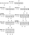
- FIG. 1 is a process cross-sectional view schematically showing an example of a method for producing a low refractive index layer and a method for producing a low refractive index layer-containing adhesive sheet according to the present invention.
- FIG. 2 is a diagram schematically showing a part of the steps of the method for producing a low refractive index layer and the method for producing an adhesive sheet containing a low refractive index layer of the present invention, and an example of an apparatus used therefor.
- FIG. 3 is a diagram schematically showing a part of the steps of the method for producing a low refractive index layer and the method for producing a low refractive index layer-containing adhesive sheet according to the present invention and another example of an apparatus used therefor.
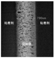
- FIG. 4 is a cross-sectional SEM image of the low refractive index layer-containing adhesive sheet of the example.
- the total thickness of the first adhesive layer and the second adhesive layer is the first adhesive layer, the low adhesive layer.
- the total thickness of the refractive index layer and the second adhesive layer may be 85% or more, 88% or more, 90% or more, or 92% or more, for example, 99.9% Hereinafter, it may be 99.5% or less, 99.3% or less, or 99.2% or less.
- the light transmittance of the laminate of the first adhesive layer, the low refractive index layer, and the second adhesive layer is 80%. It may be the above. Further, for example, the haze of the laminate of the first adhesive layer, the low refractive index layer, and the second adhesive layer may be 3% or less.
- the light transmittance may be, for example, 82% or more, 84% or more, 86% or more, or 88% or more, and the upper limit is not particularly limited, but is ideally 100%, for example, 95 % Or less, 92% or less, 91% or less, or 90% or less.
- the measurement of the haze of the laminate can be performed, for example, by the same method as the measurement of the haze of the low refractive index layer described later.
- the said light transmittance is the transmittance
- the low refractive index layer may be a void layer.
- the low refractive index layer-containing pressure-sensitive adhesive sheet of the present invention includes, for example, a separator on a surface opposite to the low refractive index layer in at least one of the first adhesive layer and the second adhesive layer. May be affixed.
- the method for producing the first low refractive index layer-containing adhesive sheet according to the present invention includes the low refractive index layer forming step of forming the low refractive index layer on the transfer resin film substrate, and the low refractive index layer forming step.
- a relatively small thickness is referred to as a “film” and a relatively large thickness is referred to as a “sheet”.
- film and “sheet” may be distinguished. There is no particular distinction.
- seat in this invention is the separator sticking process which attaches the said separator to the surface on the opposite side to the said low refractive index layer in the said adhesive layer further, for example. You may have.
- the manufacturing method of the 1st low refractive index layer containing adhesive sheet in this invention has the transfer resin film base material peeling process which peels the said transfer resin film base material after the said separator sticking process further, for example. It may be. In this case, it is preferable that the peeling force between the separator and the adhesive layer is greater than the peeling force between the transfer resin film substrate and the low refractive index layer.
- the transfer resin film substrate may be formed of an alicyclic structure-containing resin or an aliphatic structure-containing resin.
- an alicyclic structure-containing resin having excellent heat resistance from the viewpoint of durability against heat drying during formation of the low refractive index layer.
- said aliphatic structure containing resin For example, polyolefin, a polypropylene, polymethylpentene etc. are mentioned.
- the alicyclic structure-containing resin is not particularly limited, and examples thereof include polynorbornene and cyclic olefin copolymer.
- the optical device of the present invention is not particularly limited, and examples thereof include a liquid crystal display, an organic EL (Electro Luminescence) display, a micro LED (Light Emitting Diode) display, and an organic EL illumination.
- a liquid crystal display an organic EL (Electro Luminescence) display, a micro LED (Light Emitting Diode) display, and an organic EL illumination.
- an organic EL Electro Luminescence
- micro LED Light Emitting Diode
- the total thickness including the low refractive index layer greatly increases depending on the thickness of the substrate.
- the thickness of the device itself, in which thinning is important also increases.
- the low refractive index layer-containing pressure-sensitive adhesive sheet of the present invention can be reduced in thickness by not including, for example, a base material. Specifically, for example, by not including a substrate, there is almost no increase in thickness other than the thickness of the adhesive layer itself, and a low refractive index layer function can be introduced into the device. Moreover, since the adhesive layer is directly laminated on one or both sides of the low refractive index layer of the present invention, the adhesive layer containing the low refractive index layer of the present invention, the adhesive layer, The low refractive index layer is protected from physical damage. For this reason, the fragility of the low refractive index layer can be prevented from becoming a fatal problem.
- the adhesive layer can supplement the scratch resistance of the low refractive index layer, and can protect the low refractive index layer from scratches.
- the low refractive index layer containing adhesive sheet of this invention can be stuck to another member by the said adhesive layer, it is easy to introduce
- the manufacturing method of the low refractive index layer containing adhesive sheet of this invention is not specifically limited, For example, in the said manufacturing method of the 1st low refractive index layer containing adhesive sheet in this invention, or in the said this invention It can carry out by the manufacturing method of a 2nd low refractive index layer containing adhesive sheet. Hereinafter, an example will be described. In addition, in the following, the manufacturing method of the 1st low refractive index layer containing adhesive sheet in the said invention and the manufacturing method of the 2nd low refractive index layer containing adhesive sheet in this invention are put together.
- the low refractive index layer that is a component of the low refractive index layer-containing adhesive sheet of the present invention may be referred to as “low refractive index layer of the present invention”.
- the method for producing the low refractive index layer of the present invention may be referred to as “the method for producing the low refractive index layer of the present invention”.
- the low refractive index layer of the present invention may be formed of, for example, a silicon compound. Further, the low refractive index layer of the present invention may be, for example, a low refractive index layer formed by chemical bonding between microporous particles. For example, the fine pore particles may be a crushed gel.
- the gel pulverization step for pulverizing the gel of the porous body may be performed in one step, but is preferably performed in a plurality of pulverization steps.
- the number of pulverization stages is not particularly limited, and may be two stages or three or more stages, for example.
- the plurality of pulverization steps include a first pulverization step and a second pulverization step for pulverizing the gel
- the first pulverization step includes:
- the gel is pulverized into particles having a volume average particle size of 0.5 to 100 ⁇ m
- the second pulverization step further pulverizes the particles after the first pulverization step to obtain a volume average particle size. It may be a step of forming particles of 10 to 1000 nm.
- the plurality of pulverization stages may or may not include a pulverization stage other than the first pulverization stage and the second pulverization stage.
- the shape of the “particles” is not particularly limited, and may be, for example, spherical or non-spherical.
- the particles of the pulverized product may be, for example, sol-gel bead-like particles, nanoparticles (hollow nanosilica / nanoballoon particles), nanofibers, or the like.
- the gel is preferably a porous gel, and the pulverized product of the gel is preferably porous, but is not limited thereto.
- the gel pulverized product may have, for example, a structure having at least one of a particle shape, a fiber shape, and a flat plate shape.
- the particulate and flat structural units may be made of an inorganic substance, for example.
- the constituent element of the particulate structural unit may include at least one element selected from the group consisting of Si, Mg, Al, Ti, Zn, and Zr, for example.
- the structure (structural unit) that forms the particles may be a real particle or a hollow particle, and specifically includes silicone particles, silicone particles having fine pores, silica hollow nanoparticles, silica hollow nanoballoons, and the like.
- the fibrous structural unit is, for example, a nanofiber having a diameter of nanometer, and specifically includes cellulose nanofiber, alumina nanofiber, and the like.
- the plate-like structural unit include nanoclay, specifically, nano-sized bentonite (for example, Kunipia F [trade name]) and the like.
- the fibrous structural unit is not particularly limited, but for example, from the group consisting of carbon nanofiber, cellulose nanofiber, alumina nanofiber, chitin nanofiber, chitosan nanofiber, polymer nanofiber, glass nanofiber, and silica nanofiber. It may be at least one fibrous material selected.
- the gel pulverization step (for example, the plurality of pulverization steps, for example, the first pulverization step and the second pulverization step) may be performed by, for example, “others”. May be carried out in a "solvent”. The details of the “other solvent” will be described later.
- the “solvent” for example, a solvent for producing a gel, a solvent for producing a low refractive index layer, a solvent for substitution, etc.
- the “solvent” may not dissolve the gel or a pulverized product thereof.
- the pulverized product or the like may be dispersed or precipitated in the solvent.
- the volume average particle diameter of the gel after the first pulverization step may be, for example, 0.5 to 100 ⁇ m, 1 to 100 ⁇ m, 1 to 50 ⁇ m, 2 to 20 ⁇ m, or 3 to 10 ⁇ m.
- the volume average particle diameter of the gel after the second pulverization step may be, for example, 10 to 1000 nm, 100 to 500 nm, or 200 to 300 nm.
- the volume average particle diameter indicates the particle size variation of the pulverized product in the liquid containing the gel (gel-containing liquid).
- the volume average particle diameter is measured by, for example, a particle size distribution evaluation apparatus such as a dynamic light scattering method and a laser diffraction method, and an electron microscope such as a scanning electron microscope (SEM) and a transmission electron microscope (TEM). Can do.
- a particle size distribution evaluation apparatus such as a dynamic light scattering method and a laser diffraction method
- an electron microscope such as a scanning electron microscope (SEM) and a transmission electron microscope (TEM).
- the shear viscosity of the liquid immediately after the first pulverization step is, for example, 50 mPa / s or more, 1000 mPa ⁇ s or more, 2000 mPa ⁇ s or more, or 3000 mPa ⁇ s or more at a shear rate of 10001 / s.
- it may be 100 Pa ⁇ s or less, 50 Pa ⁇ s or less, or 10 Pa ⁇ s or less.
- the shear viscosity of the liquid immediately after the second pulverization step may be, for example, 1 mPa ⁇ s or more, 2 mPa ⁇ s or more, or 3 mPa ⁇ s or more, for example, 1000 mPa ⁇ s or less, 100 mPa ⁇ s or less, or It may be 50 mPa ⁇ s or less.
- the method for measuring the shear viscosity is not particularly limited. For example, as described in the examples below, the shear viscosity can be measured using a vibration type viscosity measuring machine (trade name FEM-1000V, manufactured by Seconic).
- the liquid containing the particles may have a shear viscosity of 50 mPa ⁇ s or more, and the particles may have a volume average particle diameter of 0.5 to 50 ⁇ m.
- the method for producing a low refractive index layer of the present invention preferably includes, for example, a concentration adjusting step for adjusting the concentration of the liquid containing the gel after the solvent replacement step and before the start of the first pulverization step. May be. In the case of including the concentration adjusting step, for example, it is preferable not to adjust the concentration of the liquid containing the gel after the start of the first pulverization stage.
- the gel concentration of the liquid containing the porous gel is, for example, 1% by weight or more, 1.5% by weight or more, 1.8% by weight or more, 2.0% by weight or more, or 2.8. It may be adjusted to not less than 5% by weight, for example, not more than 5% by weight, 4.5% by weight or less, 4.0% by weight or less, 3.8% by weight or less, or 3.4% by weight or less. good.
- the gel concentration of the liquid containing the gel is, for example, 1 to 5% by weight, 1.5 to 4.0% by weight, 2.0 to 3.8% by weight, or 2.8 to 3%. It may be adjusted to 4% by weight.
- the gel concentration is not too high so that the viscosity does not become too high. Further, from the viewpoint of use as a coating liquid described later, it is preferable that the gel concentration is not too low so that the viscosity does not become too low.
- the gel concentration of the liquid containing the gel is measured, for example, by measuring the weight of the liquid and the weight of the solid content (gel) after removing the solvent of the liquid, and dividing the measured value of the latter by the former measured value. Can be calculated.
- the concentration adjusting step for example, in order to appropriately adjust the gel concentration of the liquid containing the gel, the concentration may be decreased by adding a solvent, or the concentration may be increased by solvent volatilization.
- the concentration adjustment step for example, if the gel concentration of the liquid containing the gel is measured, if the gel concentration is appropriate, the concentration is not decreased or the concentration is not increased (concentration adjustment). Alternatively, it may be used for the next step as it is.
- the concentration adjusting step for example, if it is clear that the gel concentration of the liquid containing the gel is appropriate without measurement, the liquid containing the gel is not subjected to any measurement and concentration adjustment. You may use for the next process as it is.
- the change in the weight% concentration of the liquid containing the gel from immediately before the start of the first pulverization step to immediately after the end of the final pulverization step is, for example, within ⁇ 3%, within ⁇ 2.8%, ⁇ 2 It may be within 6%, within ⁇ 2.4%, or within ⁇ 2.2%.
- the method for producing a low refractive index layer of the present invention preferably further includes a gel form control step for controlling the shape and size of the gel prior to the solvent replacement step.
- a gel form control step it is preferable to control so that the size of the gel does not become too small. If the size of the gel is not too small, a large amount of solvent will adhere around the finely crushed gel, causing the measured value of the solvent concentration to be lower than the actual concentration or to remain higher than the actual concentration. This is because it is easy to prevent the problem that the measurement variation is large. Further, prior to the solvent replacement step, if the size of the gel is not too large, the solvent replacement efficiency is good. Moreover, it is preferable to control so that the size of each gel may become substantially uniform after the said gel form control process.
- the size of each gel is almost uniform, dispersion of gel pulverized product-containing liquid between each lot of gel pulverized product particle size, gel concentration and other variations can be suppressed, and the gel pulverized product-containing solution has excellent uniformity. It is because it is easy to obtain.
- the minor axis of the gel may be controlled to be, for example, 0.5 cm or more, 0.6 cm or more, 0.7 cm or more, or 0.8 cm or more, for example, 15 cm or less. , 13 cm or less, 10 cm or less, or 8 cm or less.
- the major axis of the gel may be controlled to be, for example, 30 cm or less, less than 30 cm, 28 cm or less, 25 cm or less, or 20 cm or less, for example, 1 cm or more, 2 cm or more, You may control so that it may become 3 cm or more, 4 cm or more, or 5 cm or more.
- the “minor axis” of a solid refers to a length measured at a position where the length is the shortest at a position where the length of the solid can be measured.
- the “major axis” of a solid refers to a length measured at a place where the length is the longest at a place where the length of the solid can be measured.
- the shape of the gel after the gel form control step is not particularly limited, and is, for example, a rectangular parallelepiped (including a cube), a cylindrical shape, a polygonal solid (for example, a polygonal column such as a triangular prism, a hexagonal column), a spherical shape, or What is necessary is just to control so that it may become an elliptical sphere (for example, shape like a rugby ball).
- the shape of the gel is controlled to be a rectangular parallelepiped or a substantially rectangular parallelepiped.
- the short side is controlled to be, for example, 0.5 cm or more, 0.6 cm or more, 0.7 cm or more, or 0.8 cm or more. For example, it may be controlled to be 15 cm or less, 13 cm or less, 10 cm or less, or 8 cm or less.
- the said gel form control process when controlling so that the said gel may become a rectangular parallelepiped, even if it controls so that a long side may be 30 cm or less, less than 30 cm, 28 cm or less, 25 cm or less, or 20 cm or less, for example.
- the “short side” of the rectangular parallelepiped refers to the shortest piece, and the “long side” refers to the longest piece.
- the gel form control step may be performed after the gel manufacturing step for manufacturing the gel, or may be performed during the gel manufacturing step (simultaneously with the gel manufacturing step). More specifically, for example, as follows.
- the gel may be controlled to the solid by cutting the gel in a state where the gel is fixed.
- the gel is extremely brittle, when the gel is cut, the gel may collapse unevenly regardless of the cutting direction. Therefore, by fixing the periphery of the gel, the pressure in the compression direction at the time of cutting is uniformly applied to the gel itself, so that the gel can be cut uniformly in the cutting direction.
- the shape of the gel before the solvent replacement step is substantially a rectangular parallelepiped, and in the gel shape control step, five of the six surfaces of the substantially rectangular parallelepiped gel surface are in contact with other substances.
- the gel may be cut by inserting a cutting jig into the gel from the exposed surface while the gel is fixed and the other surface is exposed.
- the cutting jig is not particularly limited, and examples thereof include a knife, a wire-like thin jig, and a thin and sharp plate-like jig. Moreover, you may perform the cutting
- the gel may be controlled to the solid by solidifying the gel raw material in a form (container) corresponding to the shape and size of the solid.
- a form corresponding to the shape and size of the solid.
- the gel concentration of the liquid containing the gel is measured, Only the liquid having a concentration within a predetermined numerical range may be subjected to the subsequent pulverization step.
- the gel concentration it is necessary to be a uniform liquid.
- the liquid is hard to separate to some extent with high viscosity after the pulverization step.
- the gel concentration is not too high because the viscosity does not become too high, and from the viewpoint of using as a coating liquid, the viscosity is not too low. It is preferred that the gel concentration is not too low. For example, from such a point of view, only the liquid having the gel concentration within a predetermined numerical range may be consistently provided until after the final pulverization stage.
- the predetermined numerical range of the gel concentration is, for example, as described above, and may be, for example, 2.8% by weight or more and 3.4% by weight or less, but is not limited thereto.
- the gel concentration measurement may be performed after the end of the first pulverization stage and before the end of the final pulverization stage, but in addition to or instead of this, the solvent substitution step It may be performed either before or after the gel pulverization step and after the final pulverization step (for example, the second pulverization step).
- concentration measurement for example, only the said liquid whose said gel density
- the concentration control after the solvent replacement step and before the gel grinding step the amount of solvent adhering to the gel is unstable, and thus there may be a large variation in each measurement of the concentration measurement value. Therefore, it is preferable to control the shape and size of the gel to be substantially uniform by the above-described gel form control step prior to the concentration management after the solvent replacement step and before the gel grinding step. Thereby, the concentration can be stably measured. Thereby, for example, it is possible to manage the gel concentration of the gel-containing liquid in a unified and accurate manner.
- the pulverization methods in the plurality of pulverization steps may all be different, but there may be a pulverization step performed by the same pulverization method.
- the plurality of pulverization stages are three stages, all three stages may be performed in different ways (that is, using three pulverization methods), and any two pulverization steps may be performed in the same pulverization method. It is also possible to carry out the other pulverization step in a different pulverization mode.
- the pulverization method is not particularly limited, and examples thereof include a cavitation method and a medialess method described later.
- the gel pulverized product-containing liquid is, for example, a sol liquid containing particles (pulverized product particles) obtained by pulverizing the gel.
- the plurality of pulverization steps include a coarse pulverization step and a main pulverization step, and after obtaining coarse sol particles by the coarse pulverization step, A sol particle maintaining a solid gel network may be obtained.
- the method for producing a low refractive index layer of the present invention for example, after at least one of the plurality of pulverization steps (for example, at least one of the first pulverization step and the second pulverization step), It further includes a classification step of classifying the particles.
- the method for producing a low refractive index layer of the present invention includes, for example, a gelation step in which a massive porous body is gelled in a solvent to form the gel.
- a gelation step in which a massive porous body is gelled in a solvent to form the gel.
- the gel gelled by the gelation process is used in the first pulverization stage (for example, the first pulverization stage) among the plurality of pulverization stages.
- the method for producing a low refractive index layer of the present invention includes, for example, an aging step of aging the gelled gel in a solvent.
- the gel after the aging step is used in the first pulverization step (for example, the first pulverization step) among the plurality of pulverization steps.
- the solvent replacement step of replacing the solvent with another solvent is performed.
- the gel in the other solvent is used in the first pulverization step (for example, the first pulverization step) among the plurality of pulverization steps.
- the shear viscosity of the liquid is controlled while measuring.
- At least one of the plurality of pulverization steps (for example, at least one of the first pulverization step and the second pulverization step) of the method for producing a low refractive index layer of the present invention is performed by, for example, high-pressure medialess pulverization. Do.
- the gel is, for example, a silicon compound gel containing at least a trifunctional or lower saturated bond functional group.
- the gel pulverized product-containing liquid obtained by the step including the gel pulverization step may be referred to as “the gel pulverized product-containing liquid of the present invention”.
- the present invention as a functional porous body is formed by forming the coating film and chemically bonding the pulverized products in the coating film.
- the low refractive index layer can be formed.
- the gel pulverized product-containing liquid of the present invention for example, the low refractive index layer of the present invention can be applied to various objects. Therefore, the gel pulverized product-containing liquid and the production method thereof of the present invention are useful, for example, in the production of the low refractive index layer of the present invention.
- the gel pulverized product-containing liquid of the present invention has, for example, extremely excellent uniformity, for example, when the low refractive index layer of the present invention is applied to uses such as optical members, the appearance is good. Can be.
- the gel pulverized product-containing liquid of the present invention is, for example, coated (coated) on the substrate and further dried. It may be a gel pulverized product-containing liquid. Moreover, the gel pulverized product-containing liquid of the present invention may be, for example, a gel pulverized product-containing liquid for obtaining a high porosity porous material (large thickness or massive bulk material). The bulk body can be obtained, for example, by performing bulk film formation using the gel pulverized product-containing liquid.
- the low refractive index layer of the present invention may be a void layer.
- the low refractive index layer of the present invention which is a void layer may be referred to as “the void layer of the present invention”.
- a step of producing the gel pulverized product-containing liquid of the present invention, a step of coating the gel pulverized product-containing liquid on a substrate to form a coating film, and a step of drying the coating film The void layer of the present invention having a high porosity can be produced by the production method including the above.
- the step of producing the gel crushed product-containing liquid of the present invention, the step of feeding out the roll-shaped resin film, and the coating of the gel crushed product-containing solution on the fed out resin film A process comprising a step of forming a film, a step of drying the coating film, and a step of winding the laminated film in which the low refractive index layer of the present invention is formed on the resin film after the drying step
- a laminated film roll can be produced by the method.
- such a production method may be referred to as a “production method of the laminated film roll of the present invention”.
- the laminated film roll manufactured by the manufacturing method of the laminated film roll of this invention may be called "the laminated film roll of this invention.”
- the gel pulverized product-containing liquid of the present invention includes, for example, a gel pulverized product pulverized by the gel pulverization step (for example, the first pulverization step and the second pulverization step) and the other solvent.
- the method for producing a low refractive index layer of the present invention may include, for example, a plurality of stages of gel crushing steps for crushing the gel (for example, porous gel) as described above. And the second pulverization step.
- the case where the method for producing a gel pulverized product-containing liquid of the present invention includes the first pulverization step and the second pulverization step will be mainly described as an example.
- the case where the said gel is a porous body (porous body gel) is mainly demonstrated.
- the present invention is not limited to this, and the description of the case where the gel is a porous body (porous body gel) can be applied by analogy other than the case where the gel is a porous body.
- the plurality of pulverization steps (for example, the first pulverization step and the second pulverization step) in the method for producing a low refractive index layer of the present invention may be collectively referred to as “gel pulverization step”.
- the gel pulverized product-containing liquid of the present invention can be used for the production of a functional porous body having the same function as the air layer (for example, low refractive index) as described later.
- the functional porous body may be, for example, the low refractive index layer of the present invention.
- the gel pulverized product-containing liquid obtained by the production method of the present invention contains the pulverized product of the porous gel, and the pulverized product has a three-dimensional structure of the unpulverized porous gel destroyed. , A new three-dimensional structure different from the uncrushed porous gel can be formed.
- a coating film (precursor of a functional porous body) formed using the gel pulverized material-containing liquid is not obtained in a layer formed using the unground porous gel. It becomes a layer in which a pore structure (new void structure) is formed. Thereby, the layer can exhibit the same function as the air layer (for example, the same low refractive index).
- the gel pulverized product-containing liquid of the present invention has a new three-dimensional structure formed as the coating film (precursor of a functional porous body), for example, because the pulverized product contains residual silanol groups. The pulverized product can be chemically bonded to each other.
- the formed functional porous body has a structure having voids, sufficient strength and flexibility can be maintained. For this reason, according to this invention, a functional porous body can be provided to various objects easily and simply.
- the gel pulverized product-containing liquid obtained by the production method of the present invention is very useful, for example, in the production of the porous structure that can be used as a substitute for the air layer.
- the air layer for example, it is necessary to form an air layer between the members by stacking the members with a gap provided therebetween via a spacer or the like.
- the functional porous body formed using the gel pulverized product-containing liquid of the present invention can exhibit the same function as the air layer only by placing it at a target site. Therefore, as described above, functions similar to the air layer can be imparted to various objects more easily and simply than forming the air layer.
- the gel pulverized product-containing liquid of the present invention can also be referred to as, for example, the functional porous body forming solution or the low refractive layer forming solution.
- the porous body is a pulverized product thereof.
- the range of the volume average particle diameter of the pulverized product (porous gel particles) is, for example, 10 to 1000 nm, 100 to 500 nm, and 200 to 300 nm.
- the said volume average particle diameter shows the particle size variation of the said ground material in the gel ground material containing liquid of this invention.
- the volume average particle diameter is, for example, a particle size distribution evaluation apparatus such as a dynamic light scattering method or a laser diffraction method, and an electron microscope such as a scanning electron microscope (SEM) or a transmission electron microscope (TEM). Can be measured.
- the gel concentration of the pulverized product is not particularly limited.
- particles having a particle size of 10 to 1000 nm are 2.5 to 4.5% by weight, 2.7 to 2.7%. It is 4.0% by weight and 2.8 to 3.2% by weight.
- the gel for example, porous gel
- examples thereof include a silicon compound.
- the silicon compound is not particularly limited, and examples thereof include a silicon compound containing at least a trifunctional or lower saturated bond functional group.
- the above-mentioned “including a saturated bond functional group having 3 or less functional groups” means that the silicon compound has 3 or less functional groups, and these functional groups are saturatedly bonded to silicon (Si). Means.
- the silicon compound is, for example, a compound represented by the following formula (2).
- R 1 and R 2 are each a linear or branched alkyl group, R 1 and R 2 may be the same or different, R 1 s may be the same as or different from each other when X is 2. R 2 may be the same as or different from each other.
- X and R 1 are, for example, the same as X and R 1 in the formula (1).
- R 2 is, for example, can be exemplified for R 1 is incorporated in the formula (1) described later.
- the silicon compound represented by the formula (2) include a compound represented by the following formula (2 ′) in which X is 3.
- R 1 and R 2 are the same as those in the formula (2), respectively.
- the silicon compound is trimethoxy (methyl) silane (hereinafter also referred to as “MTMS”).
- the concentration of the pulverized product of the porous gel in the solvent is not particularly limited, and is, for example, 0.3 to 50% (v / v), 0.5 to 30% ( v / v), 1.0 to 10% (v / v).
- concentration of the pulverized product is too high, for example, the fluidity of the gel pulverized product-containing liquid is remarkably lowered, and there is a possibility of generating aggregates and coating streaks during coating.
- the concentration of the pulverized product is too low, for example, not only does it take a considerable time to dry the solvent, but also the residual solvent immediately after drying increases, so the porosity may decrease. .
- the physical properties of the gel pulverized product-containing liquid of the present invention are not particularly limited.
- the shear viscosity of the gel pulverized product-containing liquid is, for example, 1 mPa ⁇ s to 1 Pa ⁇ s, 1 mPa ⁇ s to 500 mPa ⁇ s, 1 mPa ⁇ s to 50 mPa ⁇ s, 1 mPa ⁇ s at a shear rate of 10001 / s.
- shear viscosity is too high, for example, coating streaks may occur, and defects such as a decrease in the transfer rate of gravure coating may be observed.
- shear viscosity is too low, for example, the wet coating thickness at the time of coating cannot be increased, and a desired thickness may not be obtained after drying.
- examples of the solvent include a dispersion medium.
- the dispersion medium (hereinafter also referred to as “coating solvent”) is not particularly limited, and examples thereof include a gelling solvent and a grinding solvent described later, and the grinding solvent is preferable.
- the coating solvent includes an organic solvent having a boiling point of 70 ° C. or higher and lower than 180 ° C. and a saturated vapor pressure at 20 ° C. of 15 kPa or lower.
- organic solvent examples include carbon tetrachloride, 1,2-dichloroethane, 1,1,2,2-tetrachloroethane, trichloroethylene, isobutyl alcohol, isopropyl alcohol, isopentyl alcohol, 1-pentyl alcohol (pentanol), Ethyl alcohol (ethanol), ethylene glycol monoethyl ether, ethylene glycol monoethyl ether acetate, ethylene glycol mono-normal-butyl ether, ethylene glycol monomethyl ether, xylene, cresol, chlorobenzene, isobutyl acetate, isopropyl acetate, isopentyl acetate, ethyl acetate, Normal-butyl acetate, normal-propyl acetate, normal-pentyl acetate, cyclohexanol, cyclohexanone, 1,4-dioxa , N, N-dimethylformamide, s
- the gel pulverized material-containing liquid of the present invention includes, for example, a sol particle liquid that is the sol-like pulverized material dispersed in the dispersion medium.
- the gel pulverized product-containing liquid of the present invention for example, continuously forms a void layer having a film strength of a certain level or more by performing chemical crosslinking by a bonding step described later after coating and drying on a substrate.
- “sol” means that a three-dimensional structure of a gel is pulverized so that a pulverized product (that is, a nano-three-dimensional porous sol particle retaining a part of a void structure) is dissolved in a solvent. The state which disperse
- the gel pulverized product-containing liquid of the present invention may contain, for example, a catalyst for chemically bonding the gel pulverized products.
- the content of the catalyst is not particularly limited, and is, for example, 0.01 to 20% by weight, 0.05 to 10% by weight, or 0.1 to 5% by weight with respect to the weight of the pulverized product of the gel. .
- the gel pulverized product-containing liquid of the present invention may further contain, for example, a crosslinking aid for indirectly bonding the gel pulverized products.
- a crosslinking aid for indirectly bonding the gel pulverized products.
- the content of the crosslinking aid is not particularly limited.
- the content is 0.01 to 20% by weight, 0.05 to 15% by weight, or 0.1 to 10% by weight with respect to the weight of the pulverized gel. It is.
- the proportion of functional groups that do not contribute to the intra-gel cross-linking structure among the functional groups of the constituent monomer of the gel is, for example, 30 mol% or less, 25 mol% or less, 20 mol. % Or less, 15 mol% or less, for example, 1 mol% or more, 2 mol% or more, 3 mol% or more, 4 mol% or more may be sufficient.
- the ratio of the functional group that does not contribute to the in-gel crosslinked structure can be measured, for example, as follows.
- the mixing step is a step of mixing the porous gel particles (pulverized product) and the solvent, and may or may not be performed.
- the mixing step for example, there is a step of mixing a pulverized product of a gel-like silicon compound (silicon compound gel) obtained from a silicon compound containing at least a trifunctional or lower saturated bond functional group and a dispersion medium.
- the pulverized product of the porous gel can be obtained from the porous gel by a gel pulverization step described later.
- the pulverized product of the porous gel can be obtained, for example, from the porous gel after the aging treatment in which the aging step described later is performed.
- the gelation step is, for example, a step of gelling a massive porous body in a solvent to form the porous body gel.
- the gelation step is a step of producing a silicon compound gel by gelling a silicon compound containing at least a trifunctional or lower functional saturated bond functional group in a solvent.
- the gelation step will be described by taking the case where the porous body is a silicon compound as an example.
- the gelation step is, for example, a step of gelling the monomer silicon compound by a dehydration condensation reaction in the presence of a dehydration condensation catalyst, whereby a silicon compound gel is obtained.
- the silicon compound gel has, for example, residual silanol groups, and the residual silanol groups are preferably adjusted as appropriate according to chemical bonding between the pulverized products of the silicon compound gel described later.
- the silicon compound is not particularly limited as long as it is gelled by a dehydration condensation reaction.
- the silicon compounds are bonded.
- the bond between the silicon compounds is, for example, a hydrogen bond or an intermolecular force bond.
- Examples of the silicon compound include a silicon compound represented by the following formula (1). Since the silicon compound of the formula (1) has a hydroxyl group, the silicon compound of the formula (1) can be hydrogen bonded or intermolecularly bonded through, for example, each hydroxyl group.
- X is 2, 3 or 4
- R 1 is a linear or branched alkyl group.
- the carbon number of R 1 is, for example, 1-6, 1-4, 1-2.
- Examples of the linear alkyl group include a methyl group, an ethyl group, a propyl group, a butyl group, a pentyl group, and a hexyl group.
- Examples of the branched alkyl group include an isopropyl group and an isobutyl group.
- X is, for example, 3 or 4.
- the silicon compound represented by the formula (1) include a compound represented by the following formula (1 ′) in which X is 3.
- R 1 is the same as in the above formula (1), and is, for example, a methyl group.
- the silicon compound is tris (hydroxy) methylsilane.
- X is 3, the silicon compound is, for example, a trifunctional silane having three functional groups.
- silicon compound represented by the formula (1) examples include a compound in which X is 4.
- the silicon compound is, for example, a tetrafunctional silane having four functional groups.
- the silicon compound may be, for example, a precursor that forms the silicon compound of the formula (1) by hydrolysis.
- the precursor is not particularly limited as long as it can generate the silicon compound by hydrolysis, and specific examples thereof include a compound represented by the formula (2).
- the production method of the present invention may include, for example, a step of hydrolyzing the precursor prior to the gelation step.
- the hydrolysis method is not particularly limited, and can be performed, for example, by a chemical reaction in the presence of a catalyst.
- the catalyst include acids such as oxalic acid and acetic acid.
- the hydrolysis reaction can be performed, for example, by slowly dropping an aqueous solution of oxalic acid into the dimethyl sulfoxide solution of the silicon compound precursor in a room temperature environment and then stirring the mixture for about 30 minutes.
- hydrolyzing the silicon compound precursor for example, by completely hydrolyzing the alkoxy group of the silicon compound precursor, further heating and immobilization after gelation / aging / void structure formation, It can be expressed efficiently.
- examples of the silicon compound include a hydrolyzate of trimethoxy (methyl) silane.
- the silicon compound of the monomer is not particularly limited, and can be appropriately selected according to the use of the functional porous body to be produced, for example.
- the silicon compound is preferably the trifunctional silane from the viewpoint of excellent low refractive index property, and also has strength (for example, scratch resistance).
- the tetrafunctional silane is preferable from the viewpoint of excellent scratch resistance.
- the said silicon compound used as the raw material of the said silicon compound gel may use only 1 type, for example, and may use 2 or more types together.
- the silicon compound may include, for example, only the trifunctional silane, may include only the tetrafunctional silane, may include both the trifunctional silane and the tetrafunctional silane, Furthermore, other silicon compounds may be included.
- the ratio is not particularly limited and can be set as appropriate.
- the gelation of the porous body such as the silicon compound can be performed, for example, by a dehydration condensation reaction between the porous bodies.
- the dehydration condensation reaction is preferably performed, for example, in the presence of a catalyst.
- the catalyst include acid catalysts such as hydrochloric acid, oxalic acid, and sulfuric acid, and ammonia, potassium hydroxide, sodium hydroxide, ammonium hydroxide, and the like.
- a dehydration condensation catalyst such as a base catalyst.
- the dehydration condensation catalyst may be an acid catalyst or a base catalyst, but a base catalyst is preferred.
- the amount of the catalyst added to the porous body is not particularly limited, and for example, 0.01 to 10 mol, 0.05 to 7 mol, 0.1 to 5 moles.
- the gelation of the porous body such as the silicon compound is preferably performed in a solvent, for example.
- the ratio of the porous body in the solvent is not particularly limited.
- the solvent include dimethyl sulfoxide (DMSO), N-methylpyrrolidone (NMP), N, N-dimethylacetamide (DMAc), dimethylformamide (DMF), ⁇ -butyllactone (GBL), acetonitrile (MeCN), ethylene Examples thereof include glycol ethyl ether (EGEE).
- DMSO dimethyl sulfoxide
- NMP N-methylpyrrolidone
- DMAc N, N-dimethylacetamide
- DMF dimethylformamide
- GBL ⁇ -butyllactone
- MeCN acetonitrile
- ethylene examples thereof include glycol ethyl ether (EGEE).
- one type of solvent may be used, or two or more types may be used in combination.
- the solvent used for the gelation is
- the gelation conditions are not particularly limited.
- the treatment temperature for the solvent containing the porous body is, for example, 20 to 30 ° C., 22 to 28 ° C., 24 to 26 ° C., and the treatment time is, for example, 1 to 60 minutes, 5 to 40 minutes, 10 to 30 Minutes.
- the process conditions in particular are not restrict
- the gel form of the porous body obtained in the gelation step is not particularly limited.
- “Gel” generally refers to a solidified state in which a solute has a structure in which it loses independent motility due to interaction and aggregates.
- a wet gel includes a dispersion medium and a solute has a uniform structure in the dispersion medium.
- a xerogel is a network structure in which the solvent is removed and the solute has voids.
- the silicon compound gel is preferably a wet gel, for example.
- the remaining silanol group of the silicon compound gel is not particularly limited, and examples thereof include the ranges described later.
- the porous gel obtained by the gelation may be subjected, for example, to the solvent replacement step and the first pulverization step as it is, but prior to the first pulverization step, an aging treatment is performed in the aging step. You may give it.
- the gelled porous body (porous gel) is aged in a solvent.
- conditions for the aging treatment are not particularly limited, and for example, the porous gel may be incubated in a solvent at a predetermined temperature. According to the aging treatment, for example, the porous particles having a three-dimensional structure obtained by gelation can further grow the primary particles, thereby increasing the size of the particles themselves. is there.
- the contact state of the neck portion where the particles are in contact can be increased from point contact to surface contact, for example.
- the porous gel subjected to the aging treatment as described above, for example, increases the strength of the gel itself, and as a result, the strength of the three-dimensional basic structure of the pulverized product after pulverization can be further improved.
- the pore size of the void structure in which the three-dimensional basic structure is deposited It can suppress shrinking
- the lower limit of the temperature of the aging treatment is, for example, 30 ° C. or more, 35 ° C. or more, 40 ° C. or more, and the upper limit thereof is, for example, 80 ° C. or less, 75 ° C. or less, 70 ° C. or less.
- the predetermined time is not particularly limited, and the lower limit thereof is, for example, 5 hours or more, 10 hours or more, 15 hours or more, and the upper limit thereof is, for example, 50 hours or less, 40 hours or less, 30 hours or less.
- the range is, for example, 5 to 50 hours, 10 to 40 hours, 15 to 30 hours.
- the optimum conditions for aging are preferably set, for example, as described above, so that an increase in the size of the primary particles and an increase in the contact area of the neck portion can be obtained in the porous gel.
- the temperature of the aging treatment preferably takes into account, for example, the boiling point of the solvent used.
- the aging treatment for example, if the aging temperature is too high, the solvent is excessively volatilized, and there is a possibility that problems such as closing of the pores of the three-dimensional void structure occur due to the concentration of the coating solution. is there.
- the aging treatment for example, if the aging temperature is too low, the effect due to the aging is not sufficiently obtained, temperature variation with time of the mass production process increases, and a product with poor quality may be produced. There is.
- the same solvent as in the gelation step can be used, and specifically, the reaction product after the gel treatment (that is, the solvent containing the porous gel) may be applied as it is. preferable.
- the porous gel is the silicon compound gel
- the number of moles of residual silanol groups contained in the silicon compound gel after the aging treatment after gelation is, for example, the raw material used for the gelation (for example, the above-mentioned Silicon compound or precursor thereof) is the ratio of residual silanol groups when the number of moles of alkoxy groups is 100, and the lower limit is, for example, 50% or more, 40% or more, 30% or more, and the upper limit is For example, it is 1% or less, 3% or less, 5% or less, and the range is, for example, 1 to 50%, 3 to 40%, or 5 to 30%.
- the lower the number of moles of residual silanol groups For the purpose of increasing the hardness of the silicon compound gel, for example, the lower the number of moles of residual silanol groups, the better.
- the number of residual silanol groups is too high, for example, in the formation of the functional porous body, there is a possibility that the void structure cannot be maintained before the functional porous body precursor is crosslinked.
- the number of moles of residual silanol groups is too low, for example, in the bonding step, the precursor of the functional porous body cannot be crosslinked, and sufficient film strength may not be imparted.
- the above is an example of residual silanol groups.
- the silicon compound modified with various reactive functional groups as a raw material of the silicon compound gel, The same phenomenon can be applied.
- the porous gel obtained by the gelation is subjected to, for example, a aging treatment in the aging step, a solvent replacement step, and then subjected to the gel pulverization step.
- the solvent replacement step the solvent is replaced with another solvent.
- the gel crushing step is a step of crushing the porous gel as described above.
- the pulverization may be performed, for example, on the porous gel after the gelation step, or may be performed on the post-ripening porous gel that has been subjected to the aging treatment.
- a gel form control step for controlling the shape and size of the gel may be performed prior to the solvent replacement step (for example, after the aging step).
- the shape and size of the gel controlled in the gel form control step are not particularly limited, but are as described above, for example.
- the gel form control step may be performed, for example, by dividing (for example, cutting) the gel into a solid (three-dimensional body) having an appropriate size and shape.
- the gel pulverization step is performed after the solvent substitution step is performed on the gel.
- the solvent replacement step the solvent is replaced with another solvent. If the solvent is not replaced with the other solvent, for example, the catalyst and the solvent used in the gelation step remain after the aging step, and further gelation occurs over time, resulting in gel pulverization finally obtained This is because the pot life of the product-containing liquid may be affected, and the drying efficiency when the coating film formed using the gel pulverized product-containing liquid is dried may be decreased.
- the other solvent in the gel pulverization step is also referred to as a “grinding solvent”.
- the solvent for pulverization is not particularly limited, and for example, an organic solvent can be used.
- the organic solvent include solvents having a boiling point of 140 ° C. or lower, 130 ° C. or lower, a boiling point of 100 ° C. or lower, and a boiling point of 85 ° C. or lower. Specific examples include isopropyl alcohol (IPA), ethanol, methanol, n-butanol, 2-butanol, isobutyl alcohol, pentyl alcohol, propylene glycol monomethyl ether (PGME), methyl cellosolve, acetone and the like.
- the pulverizing solvent may be, for example, one type or a combination of two or more types.
- the solvent replacement step is divided into a plurality of solvent replacement steps.
- the step performed later is more than the step performed earlier.
- the hydrophilicity of the other solvent may be lowered.
- the solvent replacement efficiency can be improved, and the residual amount of the gel production solvent (for example, DMSO) in the gel can be made extremely low.
- the solvent replacement step is divided into three solvent replacement steps. In the first solvent replacement step, DMSO in the gel is first replaced with water, and then the second solvent replacement step. Then, the water in the gel may be replaced with IPA, and the IPA in the gel may be replaced with isobutyl alcohol in the third replacement step.
- the combination of the gelling solvent and the grinding solvent is not particularly limited.
- a more uniform coating film can be formed in the coating film formation described below.
- the solvent replacement step is not particularly limited, but can be performed as follows, for example. That is, first, the gel produced by the gel production process (for example, the gel after the aging treatment) is immersed or brought into contact with the other solvent, the gel production catalyst in the gel, and the alcohol component produced by the condensation reaction. , Water and the like are dissolved in the other solvent. Thereafter, the solvent in which the gel is immersed or contacted is discarded, and the gel is immersed or contacted again in a new solvent. This is repeated until the residual amount of the solvent for gel production in the gel reaches a desired amount.
- the immersion time per time is, for example, 0.5 hours or more, 1 hour or more, or 1.5 hours or more, and the upper limit is not particularly limited, but is, for example, 10 hours or less.
- the immersion of the solvent may be handled by continuous contact of the solvent with the gel.
- the temperature during the immersion is not particularly limited, but may be, for example, 20 to 70 ° C, 25 to 65 ° C, or 30 to 60 ° C.
- the solvent replacement proceeds quickly, and the amount of solvent necessary for the replacement may be small.
- the solvent replacement may be simply performed at room temperature. For example, when the solvent replacement step is performed in a plurality of solvent replacement steps, each of the plurality of solvent replacement steps may be performed as described above.
- the solvent replacement step may be performed by dividing it into a plurality of solvent replacement steps, and the step performed later may have a lower hydrophilicity than the step performed earlier.
- the substitution solvent the other solvent
- the remaining amount of the solvent for gel production in the gel is reduced. It can be very little.
- the residual amount of the solvent for gel production in the gel after the solvent substitution step is preferably 0.005 g / ml or less, more preferably 0.001 g / ml or less, particularly preferably 0.0005 g / ml or less. is there.
- the lower limit value of the residual amount of the solvent for gel production in the gel is not particularly limited, but is, for example, zero or less than or less than the detection limit value.
- the amount of residual solvent for gel production in the gel after the solvent replacement step can be measured, for example, as follows.
- the other solvent is used.
- the other solvent is preferably a void layer production solvent.
- the solvent for producing the void layer include a solvent having a boiling point of 140 ° C. or lower.
- the void layer production solvent include alcohols, ethers, ketones, ester solvents, aliphatic hydrocarbon solvents, aromatic solvents, and the like. Specific examples of the alcohol having a boiling point of 140 ° C.
- IPA isopropyl alcohol
- ether having a boiling point of 140 ° C. or lower
- ether having a boiling point of 140 ° C. or lower
- ether having a boiling point of 140 ° C. or lower
- ether having a boiling point of 140 ° C. or lower
- ketones having a boiling point of 140 ° C. or lower include acetone, methyl ethyl ketone, methyl isobutyl ketone, and cyclopentanone.
- ester solvent having a boiling point of 140 ° C.
- the solvent for producing the void layer is preferably an alcohol, an ether or an aliphatic hydrocarbon solvent.
- pulverization may be one type, for example, and may use two or more types together.
- isopropyl alcohol (IPA), ethanol, n-butanol, 2-butanol, isobutyl alcohol (IBA), pentyl alcohol, propylene glycol monomethyl ether (PGME), methyl cellosolve, heptane, and octane are low volatile at room temperature. From the aspect, it is preferable.
- the saturated vapor pressure of the solvent for producing the void layer is not too high (the volatility is not too high).
- a solvent having an aliphatic group having 3 or 4 carbon atoms is preferable, and a solvent having an aliphatic group having 4 or more carbon atoms is more preferable.
- the solvent having an aliphatic group having 3 or 4 carbon atoms may be, for example, an alcohol.
- Specific examples of such a solvent include isopropyl alcohol (IPA), isobutyl alcohol (IBA), n-butanol, 2-butanol, 1-pentanol, and 2-pentanol.
- IPA isopropyl alcohol
- IBA isobutyl alcohol
- n-butanol 2-butanol
- 2-butanol 1-pentanol
- 2-pentanol 2-pentanol.
- isobutyl alcohol ( IBA) is preferred.
- the other solvent (substitution solvent) other than the solvent substitution step performed at the end is not particularly limited, and examples thereof include alcohol, ether, and ketone.
- the alcohol include isopropyl alcohol (IPA), ethanol, methanol, n-butanol, 2-butanol, isobutyl alcohol (IBA), pentyl alcohol and the like.
- the ether include propylene glycol monomethyl ether (PGME), methyl cellosolve, ethyl cellosolve and the like.
- Specific examples of ketones include, for example, acetone.
- the other solvent (substitution solvent) only needs to be able to replace the gel production solvent or the other solvent (substitution solvent) in the previous stage.
- the other solvent (substitution solvent) other than the solvent substitution step to be performed last does not remain in the gel or the substrate (for example, resin film) at the time of coating even if it remains.
- a solvent that does not easily erode is preferable.
- the other solvent (substitution solvent) other than the last solvent substitution step is preferably alcohol.
- the other solvent is preferably an alcohol.
- the other solvent may be, for example, water or a mixed solvent containing water in an arbitrary ratio. Since water or a mixed solvent containing water is highly compatible with a highly hydrophilic gel production solvent (for example, DMSO), the gel production solvent can be easily replaced, and it is preferable from the viewpoint of cost.
- a highly hydrophilic gel production solvent for example, DMSO
- the plurality of solvent substitution steps are a step in which the other solvent is water, a step performed after that, a step in which the other solvent is a solvent having an aliphatic group having 3 or less carbon atoms, and a step thereafter.
- the other solvent may be a solvent having an aliphatic group having 4 or more carbon atoms.
- at least one of the solvent having an aliphatic group having 3 or less carbon atoms and the solvent having an aliphatic group having 4 or more carbon atoms may be an alcohol.
- the alcohol having an aliphatic group having 3 or less carbon atoms is not particularly limited, and examples thereof include isopropyl alcohol (IPA), ethanol, methanol, and n-propyl alcohol.
- the alcohol having an aliphatic group having 4 or more carbon atoms is not particularly limited, and examples thereof include n-butanol, 2-butanol, isobutyl alcohol (IBA), and pentyl alcohol.
- the solvent having an aliphatic group having 3 or less carbon atoms may be isopropyl alcohol, and the solvent having an aliphatic group having 4 or more carbon atoms may be isobutyl alcohol.
- the present inventors have found that it is very important to pay attention to the remaining amount of the solvent for gel production, for example, in order to form a void layer having a film strength under a relatively mild condition of 200 ° C. or less. It was. This knowledge is not shown in the prior art including the patent document and the non-patent document, and is a knowledge that the present inventors have found uniquely.
- the reason (mechanism) which can manufacture the void layer of a low refractive index by reducing the residual amount of the solvent for gel manufacture in a gel is unknown, it is estimated as follows, for example. That is, as described above, the solvent for producing the gel is preferably a high boiling point solvent (for example, DMSO or the like) for the progress of the gelation reaction. And, when producing a void layer by applying and drying the sol solution produced from the gel, at a normal drying temperature and drying time (not particularly limited, for example, at 100 ° C. for 1 minute, etc.) It is difficult to completely remove the high boiling point solvent. This is because if the drying temperature is too high or the drying time is too long, problems such as deterioration of the substrate may occur.
- a high boiling point solvent for example, DMSO or the like
- the “solvent” for example, the solvent for gel production, the solvent for void layer production, the solvent for substitution, etc.
- the solvent may not dissolve the gel or the pulverized product thereof.
- a pulverized product or the like may be dispersed or precipitated in the solvent.
- the solvent for gel production may have a boiling point of 140 ° C. or higher.
- the gel production solvent is, for example, a water-soluble solvent.
- the “water-soluble solvent” refers to a solvent that can be mixed with water at an arbitrary ratio.
- each solvent replacement step can be performed, for example, as follows. That is, first, the gel is immersed or brought into contact with the other solvent, and the gel production catalyst, the alcohol component produced by the condensation reaction, water, and the like in the gel are dissolved in the other solvent. Thereafter, the solvent in which the gel is immersed or contacted is discarded, and the gel is immersed or contacted again in a new solvent. This is repeated until the residual amount of the solvent for gel production in the gel reaches a desired amount.
- the immersion time per time is, for example, 0.5 hours or more, 1 hour or more, or 1.5 hours or more, and the upper limit is not particularly limited, but is, for example, 10 hours or less.
- the immersion of the solvent may be handled by continuous contact of the solvent with the gel. Further, the temperature during the immersion is not particularly limited, but may be, for example, 20 to 70 ° C, 25 to 65 ° C, or 30 to 60 ° C. When heating is performed, the solvent replacement proceeds quickly, and the amount of solvent necessary for the replacement may be small. However, the solvent replacement may be simply performed at room temperature.
- This solvent substitution step is performed a plurality of times by gradually changing the other solvent (substitution solvent) from a solvent having high hydrophilicity to a solvent having low hydrophilicity (high hydrophobicity).
- a highly hydrophilic gel-producing solvent for example, DMSO
- the other solvent (substitution solvent) is not particularly limited.
- the method for producing a gel includes the step of replacing the solvent, the step of replacing the other solvent (substitution solvent), and gradually decreasing the hydrophilicity from a solvent having higher hydrophilicity (higher hydrophobicity). ) It may be performed multiple times in place of the solvent. According to this, as above-mentioned, the residual amount of the solvent for gel manufacture in the said gel can be made very low. In addition, for example, it is possible to reduce the amount of the solvent used and to reduce the cost as compared with performing solvent replacement in one step using only the coating solvent.
- a gel pulverization step is performed in which the gel is pulverized in the pulverization solvent.
- the gel concentration may be measured as necessary, and then the gel concentration adjustment step may be performed as necessary. good.
- the gel concentration measurement after the solvent replacement step and before the gel pulverization step can be performed, for example, as follows. That is, first, after the solvent replacement step, the gel is taken out from the other solvent (grinding solvent). For example, the gel is controlled to a lump having an appropriate shape and size (for example, a block shape) by the gel form control step.
- the solid content concentration in one lump of gel is measured by a weight drying method.
- the measurement is performed with a plurality of (for example, six) chunks taken at random, and the average value and the variation in value are calculated.
- the gel concentration of the gel-containing liquid may be decreased by further adding the other solvent (grinding solvent).
- concentration adjustment process may raise the gel density
- the gel pulverization step may be performed in one stage, but is preferably performed in a plurality of pulverization stages. Specifically, for example, the first pulverization step and the second pulverization step may be performed. The gel pulverization step may be further performed in addition to the first pulverization step and the second pulverization step. That is, in the production method of the present invention, the gel pulverization step is not limited to two pulverization steps, and may include three or more pulverization steps.
- the first pulverization step is a step of pulverizing the porous gel.
- the second pulverization step is a step of further pulverizing the porous gel particles after the first pulverization step.
- the volume average particle diameter of the porous gel particles obtained by the first pulverization step and the volume average particle diameter of the porous gel particles obtained by the second pulverization step are, for example, as described above. It is.
- the method for measuring the volume average particle diameter is also as described above, for example.
- the shear viscosity of the gel pulverized product-containing liquid immediately after the first pulverization stage and immediately after the second pulverization stage is, for example, as described above.
- the method for measuring the shear viscosity is also as described above, for example.
- the gel concentration of the gel-containing liquid is measured, and only the liquid having the gel concentration within a predetermined numerical range is used for the second pulverization step.
- the concentration of the gel-containing liquid may be managed.
- the method for pulverizing the porous gel is not particularly limited, and may be performed by, for example, a high-pressure medialess pulverizer, an ultrasonic homogenizer, a high-speed rotation homogenizer, a high-pressure extrusion pulverizer, or other wet medialess pulverizer using a cavitation phenomenon. Can do.
- the first pulverization step and the second pulverization step may be performed by the same pulverization method or by different pulverization methods, but it is preferable to perform different pulverization methods.
- the pulverization method it is preferable that at least one of the first pulverization step and the second pulverization step is performed by a method of pulverizing the porous gel by controlling energy.
- the method of pulverizing the porous gel by controlling the energy include a method performed by a high-pressure medialess pulverizer.
- the pulverization strength is strong, but pulverization control (adjustment) is difficult.
- it is the method of grind
- a uniform gel pulverized product-containing liquid can be produced with a limited amount of work. For this reason, the gel pulverized product-containing liquid can be produced, for example, on a mass production basis.
- a device that performs media grinding such as a ball mill physically destroys the void structure of the gel during grinding
- a cavitation type grinding device such as a homogenizer
- the relatively weakly bonded porous particle bonding surface already contained is peeled off with a high-speed shearing force.
- pulverizing the porous gel a new sol three-dimensional structure is obtained, and the three-dimensional structure retains a void structure having a certain range of particle size distribution, for example, in the formation of a coating film.
- the void structure can be re-formed by deposition during coating and drying.
- the conditions for the pulverization are not particularly limited.
- the gel can be pulverized without volatilizing the solvent by instantaneously applying a high-speed flow.
- the work amount is excessive, for example, the sol particles are finer than the desired particle size distribution, and the void size deposited after coating / drying may become fine and may not satisfy the desired porosity. .
- the pulverization of the porous body it is preferable to control the pulverization of the porous body while measuring the shear viscosity of the liquid.
- a specific method for example, in the middle of the pulverization step, a method of adjusting a sol solution that achieves both desired shear viscosity and extremely excellent uniformity, the in-line shear viscosity of the solution is monitored, and the pulverization is performed. There is a method of feeding back to the stage. Thereby, it is possible to produce a gel pulverized product-containing liquid having both desired shear viscosity and extremely excellent uniformity. For this reason, for example, the characteristics of the gel pulverized product-containing liquid can be controlled according to the application.
- the ratio of the residual silanol groups contained in the pulverized product is not particularly limited, for example, the range exemplified for the silicon compound gel after the aging treatment It is the same.
- a classification step may be performed after at least one of the gel pulverization step (the first pulverization step and the second pulverization step).
- the particles of the porous gel are classified.
- the “classification” refers to, for example, sorting the particles of the porous gel according to the particle size.
- the classification method is not particularly limited, but can be performed using a sieve. In this way, by performing the pulverization process in a plurality of stages, the uniformity is extremely excellent as described above, and therefore, when applied to uses such as an optical member, the appearance can be improved. However, the appearance can be further improved by further performing the classification treatment.
- the ratio of the pulverized product in the solvent containing the pulverized product after the gel pulverizing step and the optional classification step is not particularly limited, and examples thereof include the conditions in the gel pulverized product-containing liquid of the present invention described above. .
- the ratio may be, for example, a condition of the solvent itself containing the pulverized product after the gel pulverization step, or a condition adjusted after the gel pulverization step and before using the gel pulverized product-containing liquid. It may be.
- a liquid for example, a suspension
- the fine pore particles crushed product of gel-like compound
- a catalyst that chemically bonds the fine pore particles is added to produce the liquid containing the fine pore particles and the catalyst.
- the amount of the catalyst to be added is not particularly limited, but is, for example, 0.01 to 20% by weight, 0.05 to 10% by weight, or 0.1 to 5% by weight with respect to the weight of the pulverized product of the gel silicon compound. %.
- the catalyst may be, for example, a catalyst that promotes cross-linking between the microporous particles.
- the fine pore particles As a chemical reaction for chemically bonding the fine pore particles, it is preferable to use a dehydration condensation reaction of residual silanol groups contained in silica sol molecules. By promoting the reaction between the hydroxyl groups of the silanol group with the catalyst, it is possible to form a continuous film that cures the void structure in a short time.
- the catalyst include a photoactive catalyst and a thermally active catalyst. According to the photoactive catalyst, for example, in the void layer forming step, the fine pore particles can be chemically bonded (for example, crosslinked) without being heated. According to this, for example, in the gap layer forming step, since the shrinkage of the entire gap layer hardly occurs, a higher porosity can be maintained.
- a substance that generates a catalyst may be used.
- a substance that generates a catalyst by light may be used, or in addition to or instead of the thermally active catalyst
- a substance that generates water may be used.
- the photocatalyst generator is not particularly limited, and examples thereof include a photobase generator (a substance that generates a basic catalyst by light irradiation), a photoacid generator (a substance that generates an acidic catalyst by light irradiation), and the like.
- a photobase generator is preferred.
- Examples of the photobase generator include 9-anthrylmethyl N, N-diethylcarbamate (trade name WPBG-018), (E) -1- [3- (2- Hydroxyphenyl) -2-propenoyl] piperidine ((E) -1- [3- (2-hydroxyphenyl) -2-propenoyl] piperidine, trade name WPBG-027), 1- (anthraquinone-2-yl) ethyl imidazolecarboxy Rate (1- (anthraquinon-2-yl) ethyl imidazolecarboxylate, trade name WPBG-140), 2-nitrophenylmethyl 4-methacryloyloxypiperidine-1-carboxylate (trade name WPBG-165), 1,2-diisopropyl- 3- [bis (dimethylamino) methylene] guanidium 2- (3-benzoylphenyl) propionate (trade name WPBG-266), 1 , 2-dicy
- the trade names including “WPBG” are trade names of Wako Pure Chemical Industries, Ltd.
- the photoacid generator include aromatic sulfonium salts (trade name SP-170: ADEKA), triarylsulfonium salts (trade name CPI101A: San Apro), and aromatic iodonium salts (trade name Irgacure 250: Ciba Japan). Company).
- the catalyst for chemically bonding the fine pore particles is not limited to the photoactive catalyst and the photocatalyst generator, and may be a thermal active catalyst or a thermal catalyst generator, for example.
- the catalyst for chemically bonding the fine pore particles examples include base catalysts such as potassium hydroxide, sodium hydroxide and ammonium hydroxide, and acid catalysts such as hydrochloric acid, acetic acid and oxalic acid. Of these, base catalysts are preferred.
- the catalyst or catalyst generator for chemically bonding the fine pore particles is added to a sol particle liquid (for example, suspension) containing the pulverized material (fine pore particles), for example, immediately before coating. Alternatively, it can be used as a mixed solution in which the catalyst or the catalyst generator is mixed with a solvent.
- the mixed liquid is, for example, a coating liquid dissolved by directly adding to the sol particle liquid, a solution in which the catalyst or catalyst generator is dissolved in a solvent, or a dispersion in which the catalyst or catalyst generator is dispersed in a solvent.
- the solvent is not particularly limited, and examples thereof include water and a buffer solution.
- the amount of the high boiling point solvent is not particularly limited, but is, for example, 0.05 times to 0.8 times, 0.1 to 0.5 times the amount of the solid content of the fine pore particle-containing liquid, In particular, the amount is 0.15 to 0.4 times.
- the high boiling point solvent is not particularly limited.
- DMSO dimethyl sulfoxide
- DMF N, N-dimethylformamide
- DMAc N-dimethylacetamide
- NMP N-methylpyrrolidone
- ⁇ - Examples include butyl lactone (GBL) and ethylene glycol ethyl ether (EGEE).
- a solvent having a boiling point of 110 ° C. or higher is preferable and not limited to the above specific examples.
- the high boiling point solvent is considered to act as a leveling agent in forming a film in which particles are formed side by side. It is preferable to use the high boiling point solvent also during gel synthesis.
- the manufacturing method of the low-refractive-index layer of this invention and the manufacturing method of a low-refractive-index layer containing adhesive sheet are given and an example is demonstrated.
- the low refractive index layer of the present invention is a porous silicone body formed of a silicon compound
- the low refractive index layer of the present invention is not limited to a silicone porous body.
- the low refractive index layer of the present invention is other than the porous silicone material, the following explanation can be applied mutatis mutandis unless otherwise specified.
- the method for producing a low refractive index layer of the present invention includes, for example, a precursor forming step of forming the precursor of the low refractive index layer using the gel pulverized product-containing liquid of the present invention, and the precursor And a bonding step of chemically bonding the pulverized products of the gel pulverized product-containing liquid.
- the precursor can also be referred to as a coating film, for example.
- a porous structure having the same function as an air layer is formed.
- the reason is estimated as follows, for example, but the present invention is not limited to this estimation.
- the case where the low refractive index layer of the present invention is a silicone porous body will be described as an example.
- the gel pulverized product-containing liquid of the present invention used in the method for producing the porous silicon body includes the pulverized product of the silicon compound gel
- the three-dimensional structure of the gel-like silica compound is dispersed in the three-dimensional basic structure. It has become a state. Therefore, in the method for producing a porous silicone body, for example, when the precursor (for example, coating film) is formed using the gel pulverized product-containing liquid, the three-dimensional basic structure is deposited, and the three-dimensional basic structure is deposited. A void structure based on the structure is formed.
- a new three-dimensional structure formed from the pulverized product of the three-dimensional basic structure, which is different from the three-dimensional structure of the silicon compound gel is formed.
- the said new three-dimensional structure is fixed.
- the said silicone porous body obtained by the manufacturing method of the said silicone porous body is a structure which has a space
- the low refractive index layer (for example, silicone porous body) obtained by the present invention can be used for a wide range of products such as a heat insulating material, a sound absorbing material, an optical member, and an ink image receiving layer, for example, as a member using a void.
- a laminated film having various functions can be produced.
- the production method of the low refractive index layer of the present invention can be referred to the explanation of the gel pulverized product-containing liquid of the present invention unless otherwise specified.
- the gel pulverized product-containing liquid of the present invention is applied onto the substrate.
- the gel pulverized product-containing liquid of the present invention is applied, for example, on a base material, and after the coating film is dried, the pulverized product is chemically bonded (for example, crosslinked) by the bonding step. It is possible to continuously form a low refractive index layer having a film strength above a certain level.
- the coating amount of the gel pulverized product-containing liquid on the substrate is not particularly limited, and can be appropriately set according to, for example, the desired thickness of the low refractive index layer of the present invention.
- the amount of the gel pulverized product-containing liquid applied to the substrate is, for example, the pulverized product per 1 m 2 of the substrate. 0.01 to 60000 ⁇ g, 0.1 to 5000 ⁇ g, and 1 to 50 ⁇ g.
- the preferable coating amount of the gel pulverized product-containing liquid is, for example, related to the concentration of the liquid, the coating method, etc., and thus it is difficult to define it uniquely.
- the porous body precursor may be subjected to a drying treatment.
- a drying treatment for example, not only the solvent (the solvent contained in the gel pulverized product-containing liquid) in the precursor of the porous body is removed, but also the sol particles are settled and deposited during the drying treatment.
- the purpose is to form a structure.
- the drying treatment temperature is, for example, 50 to 250 ° C., 60 to 150 ° C., 70 to 130 ° C.
- the drying treatment time is, for example, 0.1 to 30 minutes, 0.2 to 10 minutes, 0 .3-3 minutes.
- the drying process temperature and time are preferably lower and shorter in relation to, for example, continuous productivity and high porosity.
- the substrate is a resin film
- the substrate is extended in a drying furnace by being close to the glass transition temperature of the substrate, and formed immediately after coating. Defects such as cracks may occur in the void structure.
- the conditions are too loose, for example, since the residual solvent is included at the time of leaving the drying furnace, there is a possibility that defects in appearance such as scratches will occur when rubbing with the roll in the next process. is there.
- the drying treatment may be, for example, natural drying, heat drying, or vacuum drying.
- the drying method is not particularly limited, and for example, a general heating means can be used.
- the heating means include a hot air fan, a heating roll, and a far infrared heater.
- heat drying when it is premised on industrial continuous production, it is preferable to use heat drying.
- the solvent used is preferably a solvent having a low surface tension for the purpose of suppressing the generation of shrinkage stress accompanying the solvent volatilization during drying and the resulting cracking phenomenon of the low refractive index layer (the silicone porous body).
- the solvent include, but are not limited to, lower alcohols typified by isopropyl alcohol (IPA), hexane, perfluorohexane, and the like.
- the substrate is not particularly limited, for example, a thermoplastic resin substrate, a glass substrate, an inorganic substrate typified by silicon, a plastic molded with a thermosetting resin, an element such as a semiconductor, A carbon fiber-based material typified by carbon nanotube can be preferably used, but is not limited thereto.
- the form of the substrate include a film and a plate.
- the thermoplastic resin include polyethylene terephthalate (PET), acrylic, cellulose acetate propionate (CAP), cycloolefin polymer (COP), triacetate (TAC), polyethylene naphthalate (PEN), polyethylene (PE), and polypropylene. (PP).
- the bonding step is a step of chemically bonding the pulverized materials contained in the porous body precursor (coating film).
- the bonding step for example, the three-dimensional structure of the pulverized material in the precursor of the porous body is fixed.
- high temperature treatment at 200 ° C. or higher induces dehydration condensation of silanol groups and formation of siloxane bonds.
- the bonding step of the present invention by reacting various additives that catalyze the above dehydration condensation reaction, for example, when the substrate is a resin film, the substrate is not damaged, and the temperature is around 100 ° C.
- the void structure can be continuously formed and fixed at a relatively low drying temperature and a short processing time of less than a few minutes.
- the method of chemically bonding is not particularly limited, and can be appropriately determined according to, for example, the type of the gel (for example, silicon compound gel).
- the chemical bonding can be performed by, for example, chemical cross-linking between the pulverized products, and, for example, inorganic particles such as titanium oxide are added to the pulverized product. In this case, it is conceivable to chemically cross-link the inorganic particles and the pulverized product.
- a biocatalyst such as an enzyme is supported, a site other than the catalytic active site and the pulverized product may be chemically crosslinked.
- the present invention can be applied to, for example, not only the low refractive index layer formed by the sol particles but also an organic / inorganic hybrid low refractive index layer, a host guest low refractive index layer, etc., but is not limited thereto. .
- the bonding step can be performed, for example, by a chemical reaction in the presence of a catalyst according to the type of pulverized product of the gel (for example, silicon compound gel).
- a catalyst according to the type of pulverized product of the gel (for example, silicon compound gel).
- the chemical reaction in the present invention it is preferable to use a dehydration condensation reaction of residual silanol groups contained in the pulverized product of the silicon compound gel.
- the catalyst include base catalysts such as potassium hydroxide, sodium hydroxide and ammonium hydroxide, and acid catalysts such as hydrochloric acid, acetic acid and oxalic acid, but are not limited thereto.
- the catalyst for the dehydration condensation reaction is particularly preferably a base catalyst.
- a photoacid generating catalyst, a photobase generating catalyst, or the like that exhibits catalytic activity when irradiated with light can be preferably used.
- light for example, ultraviolet rays
- the catalyst is preferably added to the sol particle liquid containing the pulverized product immediately before coating, or used as a mixed liquid in which the catalyst is mixed with a solvent.
- the mixed liquid may be, for example, a coating liquid that is directly added and dissolved in the sol particle liquid, a solution in which the catalyst is dissolved in a solvent, or a dispersion liquid in which the catalyst is dispersed in a solvent.
- the solvent is not particularly limited, and examples thereof include water and a buffer solution as described above.
- a crosslinking aid for indirectly bonding the crushed gels may be added to the gel-containing liquid of the present invention.
- This crosslinking aid enters between the particles (the pulverized product), and the particles and the crosslinking aid interact or bond with each other, so that it is possible to bind particles that are slightly apart in distance. The strength can be increased efficiently.
- a polycrosslinked silane monomer is preferable.
- the multi-crosslinked silane monomer has, for example, an alkoxysilyl group having 2 or more and 3 or less, the chain length between alkoxysilyl groups may be 1 to 10 carbon atoms, and an element other than carbon May also be included.
- crosslinking aid examples include bis (trimethoxysilyl) ethane, bis (triethoxysilyl) ethane, bis (trimethoxysilyl) methane, bis (triethoxysilyl) methane, bis (triethoxysilyl) propane, bis (Trimethoxysilyl) propane, bis (triethoxysilyl) butane, bis (trimethoxysilyl) butane, bis (triethoxysilyl) pentane, bis (trimethoxysilyl) pentane, bis (triethoxysilyl) hexane, bis (tri Methoxysilyl) hexane, bis (trimethoxysilyl) hexane, bis (trimethoxysilyl) hexane, bis (trimethoxysilyl) hexane, bis (trimethoxysilyl) -N-butyl-N-propyl-ethane-1
- the chemical reaction in the presence of the catalyst is, for example, light irradiation or heating on the coating film containing the catalyst or the catalyst generator previously added to the gel pulverized product-containing liquid, or on the coating film. It can be carried out by light irradiation or heating after spraying the catalyst, or by light irradiation or heating while spraying the catalyst or catalyst generator.
- the catalyst is a photoactive catalyst
- the porous silicon body can be formed by chemically bonding the fine pore particles by light irradiation.
- the silicone porous body can be formed by chemically bonding the fine pore particles by heating.
- Light irradiation amount in the irradiation (energy) is not particularly limited, @ in 360nm terms, for example, 200 ⁇ 800mJ / cm 2, 250 ⁇ 600mJ / cm 2 or 300 ⁇ 400mJ / cm 2,. From the viewpoint of preventing the irradiation amount from being insufficient and the decomposition due to light absorption of the catalyst generator from proceeding and preventing the effect from becoming insufficient, an integrated light amount of 200 mJ / cm 2 or more is good. Further, from the viewpoint of preventing the base material under the low refractive index layer from being damaged and generating thermal wrinkles, an integrated light amount of 800 mJ / cm 2 or less is good.
- the wavelength of light in the light irradiation is not particularly limited, but is, for example, 200 to 500 nm, 300 to 450 nm.
- the light irradiation time in the light irradiation is not particularly limited, and is, for example, 0.1 to 30 minutes, 0.2 to 10 minutes, or 0.3 to 3 minutes.
- the conditions for the heat treatment are not particularly limited, and the heating temperature is, for example, 50 to 250 ° C., 60 to 150 ° C., 70 to 130 ° C., and the heating time is, for example, 0.1 to 30 minutes, 0.2 to 10 minutes and 0.3 to 3 minutes.
- a solvent having a low surface tension is preferable for the purpose of suppressing the generation of shrinkage stress accompanying the solvent volatilization during drying and the resulting cracking phenomenon of the low refractive index layer.
- examples thereof include, but are not limited to, lower alcohols typified by isopropyl alcohol (IPA), hexane, perfluorohexane, and the like.
- the low refractive index layer (for example, silicone porous body) of the present invention can be produced.
- the manufacturing method of the low refractive index layer of the present invention is not limited to the above.
- the low refractive index layer of the present invention that is a silicone porous body may be hereinafter referred to as “the silicone porous body of the present invention”.
- an adhesive layer is further formed on the low refractive index layer of this invention (adhesive layer formation process).
- the adhesive layer may be formed by applying (coating) a pressure-sensitive adhesive or an adhesive onto the low refractive index layer of the present invention.
- the adhesive layer may be formed.
- the base material such as the adhesive tape may be left as it is or may be peeled off from the adhesive layer.
- adherend and “adhesive layer” refer to, for example, an agent or layer premised on re-peeling of the adherend.
- adherend and “adhesive layer” refer to, for example, an agent or a layer that does not assume re-peeling of the adherend.
- pressure-sensitive adhesive and “adhesive” are not necessarily clearly distinguished, and “pressure-sensitive adhesive layer” and “adhesive layer” are not necessarily clearly distinguished.
- the adhesive or adhesive which forms the said adhesive layer is not specifically limited, For example, a general adhesive or adhesive etc. can be used.
- the pressure-sensitive adhesive or adhesive include acrylic, vinyl alcohol, silicone, polyester, polyurethane, and polyether polymer adhesives, rubber adhesives, and the like.
- an adhesive composed of a water-soluble crosslinking agent of vinyl alcohol polymers such as glutaraldehyde, melamine, and oxalic acid can be used.
- an acrylic pressure-sensitive adhesive is particularly preferable from the viewpoint of transparency and adhesive strength.
- an adhesive with a high storage elastic modulus is preferable from a durable viewpoint.
- the storage elastic modulus (G ′) at 23 ° C. of the pressure-sensitive adhesive (for example, acrylic pressure-sensitive adhesive) is, for example, 1.0 ⁇ 10 5 or more, 1.1 ⁇ 10 5 or more, or 1.2 ⁇ 10 5 or more.
- the upper limit value is not particularly limited, but is, for example, 1.0 ⁇ 10 7 or less.
- the low refractive index layer can be protected from physical damage (particularly, scratch) by the adhesive layer.
- the adhesive layer preferably has excellent pressure resistance so that the low refractive index layer is not crushed even as a low refractive index layer-containing adhesive sheet having no base material (baseless).
- the thickness of the adhesive layer is not particularly limited, and is, for example, 0.1 to 100 ⁇ m, 5 to 50 ⁇ m, 10 to 30 ⁇ m, or 12 to 25 ⁇ m.
- the low refractive index layer of the present invention thus obtained may be laminated with another film (layer) to form a laminated structure including the porous structure.
- each component may be laminated via the adhesive layer (adhesive or adhesive), for example.
- the lamination may be performed by continuous processing using a long film (so-called Roll to Roll, etc.). May be laminated with batch processing.
- base material a transfer resin film base material
- the low refractive index layer is formed by a coating step (1) of applying the gel crushed product-containing liquid 20 ′′ of the present invention onto a substrate 10, and a gel crushed product-containing liquid 20 ′.
- the low refractive index layer 20 can be formed using the base material 10 as illustrated.
- the method for forming the low refractive index layer may or may not include steps other than the steps (1) to (3) as appropriate.
- the adhesive layer coating step (4) for applying the adhesive layer 30 on the surface of the low refractive index layer 20 on the side opposite to the base material 10, and the adhesive layer 30 as a separator may be applied to the base material 10 as illustrated.
- the coating step (5) for covering with 40, the peeling step (6) for peeling off and removing the base material 10 from the low refractive index layer 20 The adhesive layer coating step (7) for coating the other adhesive layer 30 and the coating step (8) for covering the other adhesive layer 30 with the other separator 40 are performed, and the low refractive index layer 20
- surface or both surfaces of this can be manufactured.
- the adhesive layer 30 for example, separator 40
- the adhesive layer coating step (4) and the covering step (5) may be performed at the same time by sticking the adhesive tape in which the adhesive layer 30 is integrated to the low refractive index layer 20.
- the method for forming the low refractive index layer-containing adhesive sheet may or may not include steps other than the steps (1) to (8) as appropriate.
- the separator 40 covering and protecting the adhesive layer 30 is removed, and the adhesive layer 30 is exposed. Can be used.
- the coating method of the gel pulverized product-containing liquid 20 '' is not particularly limited, and a general coating method can be adopted.
- the coating method include a slot die method, a reverse gravure coating method, a micro gravure method (micro gravure coating method), a dip method (dip coating method), a spin coating method, a brush coating method, a roll coating method, and flexographic printing.
- the extrusion coating method, the curtain coating method, the roll coating method, the micro gravure coating method and the like are preferable from the viewpoints of productivity, coating film smoothness, and the like.
- the coating amount of the gel pulverized product-containing liquid 20 ′′ is not particularly limited, and can be appropriately set so that, for example, the thickness of the porous structure (low refractive index layer) 20 is appropriate.
- the thickness of the porous structure (low refractive index layer) 20 is not particularly limited, and is as described above, for example.
- the gel pulverized product-containing liquid 20 ′′ is dried (that is, the dispersion medium contained in the gel pulverized product-containing liquid 20 ′′ is removed) to form a coating film (precursor layer) 20 ′.
- the conditions for the drying treatment are not particularly limited and are as described above.
- the coating film 20 ′ containing the catalyst for example, photoactive catalyst, photocatalyst generator, thermal active catalyst or thermal catalyst generator
- the low refractive index layer 20 is formed by irradiating or heating and chemically bonding (for example, crosslinking) the pulverized materials in the coating film (precursor) 20 ′.
- the light irradiation or heating conditions in the chemical treatment step (3) are not particularly limited and are as described above.
- FIG. 2 schematically shows an example of a slot die coating apparatus and a method for forming the low refractive index layer using the same.
- FIG. 2 is a cross-sectional view, hatching is omitted for easy viewing.
- each step in the method using this apparatus is performed while the substrate 10 is conveyed in one direction by a roller.
- the conveyance speed is not particularly limited, and is, for example, 1 to 100 m / min, 3 to 50 m / min, or 5 to 30 m / min.
- a coating step (1) is performed in which the substrate roll 10 is fed from the feed roller 101 and conveyed, and the coating roll 102 applies the gel pulverized product-containing liquid 20 ′′ of the present invention to the substrate.
- the process proceeds to the drying step (2).
- a preliminary drying process is performed after a coating process (1) and prior to a drying process (2).
- the preliminary drying step can be performed at room temperature without heating.
- the heating means 111 is used.
- the heating means 111 as described above, a hot air fan, a heating roll, a far infrared heater, or the like can be used as appropriate.
- the drying step (2) may be divided into a plurality of steps, and the drying temperature may be increased as the subsequent drying step is performed.
- the chemical treatment step (3) is performed in the chemical treatment zone 120.
- the chemical treatment step (3) for example, when the dried coating film 20 ′ includes a photoactive catalyst, light irradiation is performed by lamps (light irradiation means) 121 disposed above and below the base material 10.
- lamps (light irradiation means) 121 disposed above and below the base material 10.
- a hot air fan 121 disposed above and below the substrate 10 using a hot air fan (heating means) instead of the lamp (light irradiation device) 121.
- This cross-linking treatment causes chemical bonding between the pulverized products in the coating film 20 ′, and the low refractive index layer 20 is cured and strengthened.
- steps (4) to (8) of FIG. 1 can be performed by the Roll to Roll method to produce the low refractive index layer-containing adhesive sheet. Thereafter, the manufactured low-refractive index layer-containing adhesive sheet is wound up by a winding roll 105.
- FIG. 3 schematically shows an example of a micro gravure method (micro gravure coating method) coating apparatus and a method for forming the porous structure using the same.
- the hatch is abbreviate
- each step in the method using this apparatus is performed while the substrate 10 is conveyed in one direction by a roller, as in FIG.
- the conveyance speed is not particularly limited, and is, for example, 1 to 100 m / min, 3 to 50 m / min, or 5 to 30 m / min.
- Application of the gel pulverized product-containing liquid 20 ′′ is performed using a liquid reservoir 202, a doctor (doctor knife) 203, and a micro gravure 204 as shown in the figure.
- the gel pulverized product-containing liquid 20 ′′ stored in the liquid reservoir 202 is attached to the surface of the microgravure 204, and further controlled to a predetermined thickness by the doctor 203, while being controlled by the microgravure 204. Apply to the surface of the material 10.
- the microgravure 204 is merely an example, and the present invention is not limited to this, and any other coating means may be used.
- a drying step (2) is performed. Specifically, as shown in the drawing, the base material 10 coated with the gel pulverized product-containing liquid 20 ′′ is transported into the oven zone 210, heated by the heating means 211 in the oven zone 210 and dried.
- the heating means 211 may be the same as that shown in FIG. Further, for example, by dividing the oven zone 210 into a plurality of sections, the drying step (2) may be divided into a plurality of steps, and the drying temperature may be increased as the subsequent drying step is performed.
- the chemical treatment step (3) is performed in the chemical treatment zone 220.
- the chemical treatment step (3) for example, when the dried coating film 20 ′ includes a photoactive catalyst, light irradiation is performed by lamps (light irradiation means) 221 disposed above and below the substrate 10.
- lamps (light irradiation means) 221 disposed above and below the substrate 10.
- a hot air fan (heating means) is used instead of the lamp (light irradiation device) 221 and is arranged below the base material 10 ( The substrate 10 is heated by the heating means 221.
- the crushed material in the coating film 20 ′ is chemically bonded to each other, and the low refractive index layer 20 is formed.
- steps (4) to (8) of FIG. 1 can be performed by the Roll to Roll method to produce the low refractive index layer-containing adhesive sheet. Thereafter, the produced low-refractive index layer-containing adhesive sheet is wound up by a winding roll 251.
- the low refractive index layer of the present invention is a void layer (the void layer of the present invention)
- the void layer of the present invention will be described with examples. However, these are examples and do not limit the present invention. Further, in the following, description of matters (for example, haze, refractive index, layer thickness, scratch resistance, Rz coefficient, etc.) other than matters relating to the voids themselves (for example, porosity, pore diameter, etc.) is not particularly refused. As long as the low refractive index layer of the present invention is other than the void layer, it can also be used.
- the void layer of the present invention may have a porosity of 35% by volume or more and a peak pore diameter of 50 nm or less.
- this is an exemplification, and the void layer of the present invention is not limited to this.
- the porosity may be, for example, 35% by volume or more, 38% by volume or more, or 40% by volume or more, or 90% by volume or less, 80% by volume or less, or 75% by volume or less.
- the void layer of the present invention may be, for example, a high void layer having a porosity of 60% by volume or more.
- the porosity can be measured, for example, by the following measuring method.
- the ratio (volume ratio) between the constituent material of the layer and air can be calculated by a standard method (for example, measuring the weight and volume to calculate the density). ), The porosity (volume%) can be calculated. Further, since there is a correlation between the refractive index and the porosity, for example, the porosity can be calculated from the value of the refractive index of the layer. Specifically, for example, the porosity is calculated from Lorentz-Lorenz's formula (Lorentz-Lorentz formula) from the refractive index value measured by an ellipsometer.
- the void layer of the present invention can be produced by chemical bonding of a pulverized gel (fine pore particles).
- the voids in the void layer can be divided into the following three types (1) to (3) for convenience.
- the voids in (2) above are obtained when each particle group generated by pulverizing the gel is regarded as one lump (block) regardless of the size, size, etc. of the pulverized gel (microporous particles).
- these are voids formed during pulverization.
- the voids (3) are voids caused by uneven sizes and sizes of gel pulverized products (microporous particles) in pulverization (for example, medialess pulverization).
- the void layer of the present invention has, for example, the voids (1) to (3) described above, thereby having an appropriate void ratio and peak pore diameter.
- the peak pore diameter may be, for example, 5 nm or more, 10 nm or more, or 20 nm or more, and may be 50 nm or less, 40 nm or less, or 30 nm or less.
- the lower limit value of the peak pore diameter of the void layer is not particularly limited, but if the peak pore diameter is too small, it is difficult to increase the porosity, and therefore it is preferable that the peak pore diameter is not too small.
- the peak pore diameter can be measured, for example, by the following method.
- the thickness of the void layer of the present invention is not particularly limited, and may be, for example, 100 nm or more, 200 nm or more, or 300 nm or more, or 10,000 nm or less, 5000 nm or less, or 2000 nm or less.
- the surface roughness Rz coefficient is preferably as small as possible in view of the surface strength and the like.
- the surface roughness Rz coefficient may be, for example, 100 nm or less, 95 nm or less, or 90 nm or less.
- the lower limit value of the surface roughness Rz coefficient is not particularly limited, but is, for example, 50 nm or more.
- the surface roughness Rz coefficient means a ten-point average roughness defined in JIS B 0601: 1970 / JIS B 0601: 1994.
- the surface roughness Rz coefficient (ten-point average roughness) is defined by extracting a reference length from the roughness curve in the direction of the average line, and from the average line of the extracted portion in the direction of the vertical magnification. Calculate the sum of the absolute value of the measured altitude (Yp) from the highest peak to the fifth and the average absolute value of the lowest (Yv) from the lowest valley to the fifth. , Which represents this value.
- the surface roughness Rz coefficient can be measured, for example, by a method using an atomic force microscope (AFM).
- AFM atomic force microscope
- the surface of a certain range is measured with the atomic force microscope, and the ten-point surface roughness (Rz) in that region is calculated.
- Rz ten-point surface roughness
- the void layer of the present invention has, for example, a scratch resistance of 60 to 100% by Bencot (registered trademark) indicating the film strength, and a folding resistance by the MIT test indicating flexibility is 100 times or more. Although there may be, it is not limited to this.
- the void layer of the present invention uses, for example, a pulverized product of the porous gel, the three-dimensional structure of the porous gel is destroyed, and a new three-dimensional structure different from the porous gel is formed.
- the void layer of the present invention is a layer in which a new pore structure (new void structure) that cannot be obtained by the layer formed from the porous gel is formed.
- a void layer of scale can be formed.
- the void layer of the present invention for example, when the void layer is a silicone porous body, chemically bonds the pulverized materials to each other while adjusting the number of siloxane bond functional groups of the silicon compound gel, for example.
- the void layer of the present invention includes, for example, the void layer having a functional porosity.
- the structure has voids, but sufficient strength and flexibility can be maintained. Therefore, according to the present invention, the void layer can be easily and simply applied to various objects.
- the void layer of the present invention includes, for example, a porous gel pulverized product as described above, and the pulverized product is chemically bonded to each other.
- the form of chemical bonding (chemical bonding) between the pulverized products is not particularly limited, and specific examples of the chemical bonding include, for example, cross-linking.
- the method of chemically bonding the pulverized materials is as described in detail in the above-described method for manufacturing the void layer, for example.
- the cross-linking is, for example, a siloxane bond.
- the siloxane bond include T2 bond, T3 bond, and T4 bond shown below.
- T2 bond T2 bond
- T3 bond T4 bond
- the silicone porous body of the present invention may have any one kind of bond, any two kinds of bonds, or all three kinds of bonds. Also good.
- the siloxane bonds the greater the ratio of T2 and T3, the more flexible and the expected properties of the gel can be expected, but the film strength becomes weaker.
- the T4 ratio in the siloxane bond is large, the film strength is easily expressed, but the void size becomes small and the flexibility becomes brittle. For this reason, for example, it is preferable to change the ratio of T2, T3, and T4 according to the application.
- the void layer of the present invention for example, it is preferable that contained silicon atoms have siloxane bonds.
- the proportion of unbonded silicon atoms (that is, residual silanol) in the total silicon atoms contained in the porous silicone material is, for example, less than 50%, 30% or less, or 15% or less.
- the void layer of the present invention has a pore structure, and the pore size refers to the major axis diameter of the major axis and minor axis diameter of the void (hole).
- the pore size is, for example, 5 nm to 50 nm.
- the lower limit of the void size is, for example, 5 nm or more, 10 nm or more, 20 nm or more, and the upper limit thereof is, for example, 50 nm or less, 40 nm or less, 30 nm or less, and the range thereof is, for example, 5 nm to 50 nm, 10 nm. ⁇ 40 nm. Since a preferable void size is determined depending on the use of the void structure, it is necessary to adjust the void size to a desired void size according to the purpose, for example.
- the void size can be evaluated by the following method, for example.
- the form of the void layer can be observed and analyzed using an SEM (scanning electron microscope).
- SEM scanning electron microscope
- the void layer is subjected to FIB processing (acceleration voltage: 30 kV) under cooling, and the obtained cross-sectional sample is subjected to FIB-SEM (manufactured by FEI: trade name Helios NanoLab600, acceleration voltage: 1 kV).
- FIB processing acceleration voltage: 30 kV
- FIB-SEM manufactured by FEI: trade name Helios NanoLab600, acceleration voltage: 1 kV.
- a cross-sectional electron image can be obtained at an observation magnification of 100,000.
- the void size can be quantified by a BET test method. Specifically, 0.1 g of a sample (a void layer of the present invention) was introduced into a capillary of a pore distribution / specific surface area measuring apparatus (BELLSORP MINI / trade name of Microtrack Bell), and then at room temperature for 24 hours. Vacuum drying is performed to degas the gas in the void structure. Then, by adsorbing nitrogen gas to the sample, a BET plot, a BJH plot, and an adsorption isotherm are drawn to obtain a pore distribution. Thereby, the gap size can be evaluated.
- a BET test method Specifically, 0.1 g of a sample (a void layer of the present invention) was introduced into a capillary of a pore distribution / specific surface area measuring apparatus (BELLSORP MINI / trade name of Microtrack Bell), and then at room temperature for 24 hours. Vacuum drying is performed to degas the gas in the void structure. Then, by ad
- the void layer of the present invention has, for example, a scratch resistance of 60 to 100% due to Bencot (registered trademark) indicating film strength. Since the present invention has such a film strength, for example, it is excellent in scratch resistance in various processes. The present invention, for example, has scratch resistance in the production process when winding the product after forming the void layer and handling the product film.
- the void layer of the present invention uses, for example, a catalytic reaction in a heating step described later, instead of reducing the porosity, so that the particle size of the pulverized product of the silicon compound gel and the pulverized product are The coupling force of the coupled neck portions can be increased. Thereby, the void layer of the present invention can give a certain level of strength to, for example, a void structure that is inherently brittle.
- the lower limit of the scratch resistance is, for example, 60% or more, 80% or more, 90% or more, and the upper limit thereof is, for example, 100% or less, 99% or less, 98% or less, and the range is For example, they are 60 to 100%, 80 to 99%, 90 to 98%.
- the scratch resistance can be measured by, for example, the following method.
- the residual amount of Si (Si 1 ) after the scratch test is measured by sampling and fluorescent X measurement in the same manner as in (1) above from the gap layer after sliding.
- the void layer of the present invention has a folding endurance of 100 or more by the MIT test showing flexibility. Since the present invention has such flexibility, for example, it is excellent in handleability during winding or use during production.
- the lower limit of the folding endurance number is, for example, 100 times or more, 500 times or more, 1000 times or more, and the upper limit is not particularly limited, for example, 10,000 times or less, and the range is, for example, 100 10000 times, 500 times to 10000 times, 1000 times to 10000 times.
- the flexibility means, for example, ease of deformation of the substance.
- the folding endurance by the MIT test can be measured by the following method, for example.
- the void layer (the void layer of the present invention) is cut into a 20 mm ⁇ 80 mm strip and then attached to an MIT folding tester (manufactured by Tester Sangyo Co., Ltd .: BE-202), and a load of 1.0 N is applied.
- the chuck part that embeds the gap layer uses R 2.0 mm, performs the folding endurance up to 10,000 times, and sets the number of times when the gap layer is broken as the number of folding endurances.
- the film density showing the porosity is not particularly limited, and the lower limit thereof is, for example, 1 g / cm 3 or more, 5 g / cm 3 or more, 10 g / cm 3 or more, 15 g / cm 3 or more.
- the upper limit is, for example, 50 g / cm 3 or less, 40 g / cm 3 or less, 30 g / cm 3 or less, 2.1 g / cm 3 or less, and the range thereof is, for example, 5 to 50 g / cm 3 , 10 ⁇ 40g / cm 3, 15 ⁇ 30g / cm 3, a 1 ⁇ 2.1g / cm 3.
- the film density can be measured by the following method, for example.
- the void layer of the present invention only needs to have a pore structure (porous structure) as described above, and may be, for example, an open cell structure in which the pore structure is continuous.
- the open cell structure means, for example, that the pore structure is three-dimensionally connected in the void layer, and can be said to be a state in which the internal voids of the pore structure are continuous.
- the porous body has an open cell structure, it is possible to increase the porosity occupied in the bulk.
- closed cells such as hollow silica are used, the open cell structure cannot be formed.
- the void layer of the present invention has a three-dimensional dendritic structure because the sol particles (the pulverized porous gel forming the sol) have a coating film (the porous gel pulverized product). In the sol coating film, the dendritic particles settle and deposit, so that an open cell structure can be easily formed.
- the void layer of the present invention more preferably forms a monolith structure in which the open cell structure has a plurality of pore distributions.
- the monolith structure refers to, for example, a structure in which nano-sized fine voids exist and a hierarchical structure in which the nano-voids are gathered as an open cell structure.
- the monolith structure for example, while providing film strength with fine voids, high porosity can be imparted with coarse open-cell voids, and both film strength and high porosity can be achieved.
- the monolith structure can be formed by controlling the particle size distribution of the pulverized product to a desired size.
- the tear crack generation elongation that shows flexibility is not particularly limited, and the lower limit is, for example, 0.1% or more, 0.5% or more, 1% or more, and the upper limit is For example, it is 3% or less.
- the range of the tear crack occurrence elongation is, for example, 0.1 to 3%, 0.5 to 3%, and 1 to 3%.
- the tear crack elongation rate can be measured, for example, by the following method.
- the haze indicating transparency is not particularly limited, and the lower limit thereof is, for example, 0.1% or more, 0.2% or more, 0.3% or more, and the upper limit thereof is, for example, 10% or less, 5% or less, 3% or less, and the range is, for example, 0.1 to 10%, 0.2 to 5%, or 0.3 to 3%.
- the haze can be measured by, for example, the following method.
- the void layer (the void layer of the present invention) is cut into a size of 50 mm ⁇ 50 mm, and set in a haze meter (manufactured by Murakami Color Research Laboratory Co., Ltd .: HM-150) to measure haze.
- the refractive index is generally the ratio of the transmission speed of the wavefront of light in a vacuum to the propagation speed in the medium is called the refractive index of the medium.
- the refractive index of the void layer (for example, porous silicone) of the present invention is not particularly limited, and the upper limit thereof is, for example, 1.3 or less, less than 1.3, 1.25 or less, 1.2 or less, 1.15.
- the lower limit is, for example, 1.05 or more, 1.06 or more, 1.07 or more, and the range thereof is, for example, 1.05 or more and 1.3 or less, 1.05 or more and less than 1.3. 1.05 to 1.25, 1.06 to less than 1.2, and 1.07 to 1.15.
- the refractive index means a refractive index measured at a wavelength of 550 nm unless otherwise specified.
- the measuring method of a refractive index is not specifically limited, For example, it can measure with the following method.
- a void layer (the void layer of the present invention) on the acrylic film, it is cut into a size of 50 mm x 50 mm, and this is bonded to the surface of a glass plate (thickness: 3 mm) with an adhesive layer.
- the back surface central part (diameter of about 20 mm) of the glass plate is painted with black magic to prepare a sample that does not reflect on the back surface of the glass plate.
- the sample is set in an ellipsometer (manufactured by JA Woollam Japan: VASE), the refractive index is measured under the conditions of a wavelength of 500 nm and an incident angle of 50 to 80 degrees, and the average value is taken as the refractive index.
- the thickness of the void layer of the present invention is not particularly limited, and the lower limit is, for example, 0.05 ⁇ m or more and 0.1 ⁇ m or more, and the upper limit is, for example, 1000 ⁇ m or less, 100 ⁇ m or less, and the range is For example, they are 0.05 to 1000 ⁇ m and 0.1 to 100 ⁇ m.
- the form of the void layer of the present invention is not particularly limited, and may be, for example, a film shape or a block shape.
- the method for producing the void layer of the present invention is not particularly limited, and for example, it can be produced by the aforementioned method for producing the void layer.
- an isobutyl alcohol dispersion (gel pulverized product-containing liquid) in which nanometer-sized particles (the pulverized product of the gel) were dispersed was obtained. Furthermore, 224 g of a methyl isobutyl ketone 1.5 wt% concentration solution of WPBG-266 (trade name, manufactured by Wako) was added to 3 kg of the gel pulverized product-containing solution, and bis (trimethoxylyl) ethane (manufactured by TCI) was further added. After adding 67.2 g of a 5% by weight methyl isobutyl ketone solution, 31.8 g of N, N-dimethylformamide was added and mixed to obtain a coating solution.
- WPBG-266 trade name, manufactured by Wako
- the solid content concentration (gel concentration) of the liquid was measured. 3.01% by weight.
- the volume average particle diameter of the pulverized product of the gel is 3 to 5 ⁇ m, and the shear viscosity of the liquid is It was 4,000 mPa ⁇ s.
- the measurement value after the first pulverization step was adopted as it was.
- the volume average particle diameter of the gel pulverized product was 250 to 350 nm, and the shear viscosity of the liquid was 5 m to 10 mPa ⁇ s.
- the solid content concentration (gel concentration) of the liquid (gel pulverized product-containing liquid) was measured again, and was 3.01% by weight. It was not changed after the 1st grinding stage (coarse grinding process).
- the average particle size of the gel pulverized product (sol particles) after the first pulverization step and the second pulverization step is determined by a dynamic light scattering nanotrack particle size analyzer (Nikkiso). (Product name: UPA-EX150 type). Further, in this example, the shear viscosity of the liquid after the first pulverization step and the second pulverization step was confirmed with a vibration type viscosity measuring machine (trade name FEM-1000V, manufactured by Seconic). . The same applies to the following examples and comparative examples.
- the first pulverization step in the solid content (gel) of the gel pulverized product-containing liquid, among the functional groups (silanol groups) of the constituent unit monomer, it contributes to the intragel crosslinked structure.
- Measurement (calculation) of the ratio of no functional group (residual silanol group) yielded a measurement value of 11 mol%.
- the ratio of the functional groups (residual silanol groups) that do not contribute to the intra-gel crosslinked structure is determined by measuring solid NMR (Si-NMR) after drying the gel and contributing to the crosslinked structure from the NMR peak ratio. It was measured by a method of calculating the ratio of no remaining silanol groups.
- the void layer forming coating solution (gel pulverized product-containing solution) of this reference example (reference example 1) was produced. Moreover, it was 12 nm when the peak pore diameter of the gel ground material (micropore particle
- a polyethylene terephthalate (PET) film (Mitsubishi Chemical Polyester Film Co., Ltd.) subjected to silicone treatment of the acrylic pressure-sensitive adhesive composition (acrylic pressure-sensitive adhesive solution) prepared in (2) above.
- the coated layer was formed on one surface having a thickness of 50 ⁇ m so that the dried adhesive layer (pressure-sensitive adhesive layer) had a thickness of 25 ⁇ m.
- a polyethylene terephthalate (PET) film manufactured by Mitsubishi Chemical Polyester Film Co., Ltd., thickness: 38 ⁇ m) subjected to silicone treatment was provided on the coating layer to cover the coating layer and to block oxygen, thereby forming a laminate.
- ultraviolet rays with an illuminance of 5 mW / cm 2 were irradiated for 300 seconds from the upper surface (MRF38 side) of the laminate with a black light (manufactured by Toshiba). Furthermore, the drying process was performed for 2 minutes with a 90 degreeC dryer, the remaining monomer was volatilized, and the adhesive layer (adhesive layer) was formed.
- the storage elastic modulus G ′ at 23 ° C. of this pressure-sensitive adhesive layer (adhesive layer) was 1.1 ⁇ 10 5 .
- acrylic pressure-sensitive adhesive composition For 100 parts of the solid content of the acrylic polymer solution obtained in (1) above, an isocyanate crosslinking agent (trade name “Coronate L”, Tri 0.2 parts of methylolpropane tolylene diisocyanate adduct), 0.3 parts of benzoyl peroxide (trade name “Nyper BMT” manufactured by NOF Corporation), ⁇ -glycidoxypropylmethoxysilane (manufactured by Shin-Etsu Chemical Co., Ltd.) Acrylic pressure-sensitive adhesive composition (acrylic pressure-sensitive adhesive solution) containing 0.2 part of the product name “KBM-403”) was prepared.
- an isocyanate crosslinking agent trade name “Coronate L”
- Tri 0.2 parts of methylolpropane tolylene diisocyanate adduct Tri 0.2 parts of methylolpropane tolylene diisocyanate adduct
- benzoyl peroxide trade name “Nyper BMT” manufactured by NOF
- the acrylic pressure-sensitive adhesive composition obtained in (2) above is a silicone-treated polyethylene terephthalate (PET) film (Mitsubishi Chemical Polyester Film Co., Ltd., thickness: 38 ⁇ m). It applied so that the thickness of the adhesive layer after drying might be set to 5 micrometers on one side, and it dried for 3 minutes at 150 degreeC, and formed the adhesive layer (adhesion layer).
- the storage elastic modulus G ′ at 23 ° C. of this pressure-sensitive adhesive layer (adhesive layer) was 1.3 ⁇ 10 5 .
- Example 1 A base material (base film) composed of an alicyclic structure-containing resin film having a thickness of 100 ⁇ m (Nippon Zeon Co., Ltd., trade name “Zeonor: ZF14 film”) formed from the coating solution for forming a low refractive index layer prepared in Reference Example 1. Coating and drying were carried out to form a low refractive index layer (refractive index: 1.18) having a film thickness of about 800 nm. Further, the pressure-sensitive adhesive (first adhesive layer) obtained in Reference Example 2 having a thickness of 25 ⁇ m with a separator (75 ⁇ m) was bonded onto the low refractive index layer surface, and then from the alicyclic structure-containing resin film side.
- base film composed of an alicyclic structure-containing resin film having a thickness of 100 ⁇ m (Nippon Zeon Co., Ltd., trade name “Zeonor: ZF14 film”) formed from the coating solution for forming a low refractive index layer prepared in Reference Example 1. Coating and drying
- the said alicyclic structure containing resin film (base film) was peeled from the integrated product of the said adhesive (adhesive bond layer) and a low refractive index layer.
- the pressure-sensitive adhesive (second adhesive layer) obtained in Reference Example 3 having a thickness of 5 ⁇ m with another separator was bonded to the surface from which the base film was peeled off, and the total thickness (total thickness) was about A 31 ⁇ m low refractive index layer-containing adhesive sheet was obtained.
- the total thickness (overall thickness) refers to the total thickness of the laminate [without separator] of the first adhesive layer, the low refractive index layer, and the second adhesive layer.
- This low refractive index layer-containing adhesive sheet has a thickness of the pressure-sensitive adhesive (adhesive layer) relative to the total thickness (total thickness) (of the thickness of the first adhesive layer and the second adhesive layer). The ratio of the total) was about 97%.
- Table 1 shows the optical characteristics of the low refractive index layer-containing adhesive sheet. Further, Table 1 also shows the luminance characteristic results when the light guide plate and the reflector used in the LED edge light type backlight of the liquid crystal TV are integrated using the low refractive index layer-containing adhesive sheet. .
- Example 2 A low refractive index having a total thickness (total thickness) of about 11 ⁇ m is the same as in Example 1 except that both of the pressure-sensitive adhesives described in Example 1 are the pressure-sensitive adhesives obtained in Reference Example 3.
- a layer-containing adhesive sheet was obtained.
- This low refractive index layer-containing adhesive sheet has a thickness of the pressure-sensitive adhesive (adhesive layer) relative to the total thickness (total thickness) (of the thickness of the first adhesive layer and the second adhesive layer). The ratio of the total) was about 91%.
- Table 1 shows the optical characteristics of the low refractive index layer-containing adhesive sheet. Further, Table 1 also shows the luminance characteristic results when the light guide plate and the reflector used in the LED edge light type backlight of the liquid crystal TV are integrated using the low refractive index layer-containing adhesive sheet. .
- Example 3 In the adhesive described in Example 1, the first adhesive layer was used as the adhesive (adhesive layer) obtained in Reference Example 4, and the second adhesive layer was obtained in Reference Example 5. Except for the pressure-sensitive adhesive (adhesive layer), the same operation as in Example 1 was performed to obtain a low refractive index layer-containing adhesive sheet having a total thickness (total thickness) of about 41 ⁇ m.
- This low refractive index layer-containing adhesive sheet has a thickness of the pressure-sensitive adhesive (adhesive layer) relative to the total thickness (total thickness) (of the thickness of the first adhesive layer and the second adhesive layer). The ratio of the total) was about 98%.
- Table 1 shows the optical characteristics of the low refractive index layer-containing adhesive sheet. Further, Table 1 also shows the luminance characteristic results when the light guide plate and the reflector used in the LED edge light type backlight of the liquid crystal TV are integrated using the low refractive index layer-containing adhesive sheet. .
- Example 1 Except having changed the low refractive index layer of Example 1 into the low refractive index layer of refractive index 1.28, operation similar to Example 1 was performed and the low refractive index layer containing adhesive sheet was obtained.
- Table 1 shows the optical characteristics of the low refractive index layer-containing adhesive sheet. Further, Table 1 also shows the luminance characteristic results when the light guide plate and the reflector used in the LED edge light type backlight of the liquid crystal TV are integrated using the low refractive index layer-containing adhesive sheet. .
- luminance characteristics were measured as follows.
- the low refractive index layer-containing pressure-sensitive adhesive sheet described in the examples was introduced between the light guide plate and the reflective plate of the TV having the LED edge light type backlight, and the light guide plate and the reflective plate were integrated.
- the TV was displayed in white, and the luminance at each coordinate was measured from the LED incident side to the terminal side of the light guide plate using a spectroradiometer SR-UL2 (trade name of Topcon Technohouse).
- the surface roughness Rz coefficient (10-point average roughness) of the low refractive index layer (void layer) in the low refractive index layer-containing adhesive sheets of Examples 1 to 3 and Comparative Example 1 was measured using SPI3800 manufactured by Seiko Electronics Co., Ltd. (Product name) was measured by the measurement method described above. The measurement results are also shown in Table 1.
- Comparative Example 1 in which the refractive index of the low refractive index layer exceeds 1.25 and Comparative Example 2 without the low refractive index layer, when the light guide plate and the reflective plate are integrated, the end of the light guide plate Since the light leaked before the light propagated to the side and the light did not reach the terminal side, the luminance was non-uniform.
- Comparative Example 3 using an air layer instead of the low refractive index layer-containing adhesive sheet, the reflector was bent when the light guide plate and the reflector were integrated, and the operation was difficult. Furthermore, luminance unevenness due to the deflection of the reflecting plate also occurred.
- the low refractive index layers used in Examples 1 to 3 had a surface roughness Rz coefficient as small as 87 nm, although the refractive index was extremely low as 1.18 (that is, the porosity was high).
- the numerical value of 87 nm is a numerical value that is almost comparable to the low refractive index layer of Comparative Example 1.
- the low refractive index layer having a small surface roughness Rz coefficient is easy to suppress or prevent problems such as the low strength of the surface of the low refractive index layer that is easily damaged. Therefore, it is easy to suppress or prevent a decrease in optical properties due to scratches on the surface of the low refractive index layer.
- a low refractive index layer-containing adhesive sheet that is thin and has a low refractive index
- a method for producing a low refractive index layer-containing adhesive sheet and an optical device. It can.
- the application of the present invention is not particularly limited, and can be widely used in general optical devices such as a liquid crystal display, an organic EL display, a micro LED display, and an organic EL illumination.
- Substrate 20 Low Refractive Index Layer 20 ′ Coating Film (Precursor Layer) 20 '' gel crushed product-containing liquid 30 Adhesive layer (adhesive) 40 Separator 101 Delivery roller 102 Coating roll 105 Winding roll 106 Roll 110 Oven zone 111 Hot air (heating means) 120 Chemical treatment zone 121 Lamp (light irradiation means) or hot air device (heating means) 201 Feeding roller 202 Liquid reservoir 203 Doctor (doctor knife) 204 Microgravure 210 Oven zone 211 Heating means 220 Chemical treatment zone 221 Lamp (light irradiation means) or hot air blower (heating means) 251 Winding roll
Abstract
The purpose of this invention is to provide a low refractive index layer-containing adhesive sheet, which is thin and which has a low refractive index. In order to achieve this purpose, this low refractive index layer-containing adhesive sheet is characterized by being obtained by laminating, in the following order, a first adhesive layer, a low refractive index layer, and a second adhesive layer, the refractive index of the low refractive index layer not exceeding 1.25.
Description
本発明は、低屈折率層含有粘接着シート、低屈折率層含有粘接着シートの製造方法、および光学デバイスに関する。
The present invention relates to a low refractive index layer-containing adhesive sheet, a method for producing a low refractive index layer-containing adhesive sheet, and an optical device.
光学デバイスにおいては、例えば、全反射層として、低屈折率である空気層が利用されている。具体的には、例えば、液晶デバイスにおける各光学フィルム部材(例えば、導光板と反射板)は、空気層を介して積層される。しかしながら、各部材間が空気層により隔てられていると、特に部材が大型である場合等は、部材のたわみ等の問題が起こるおそれがある。また、デバイスの薄型化のトレンドにより、各部材の一体化が望まれている。このため、各部材を、空気層を介さずに粘接着剤で一体化させることが行われている(例えば特許文献1)。しかし、全反射の役割を果たす空気層が無くなると、光漏れなど光学特性が低下してしまうおそれがある。
In optical devices, for example, an air layer having a low refractive index is used as the total reflection layer. Specifically, for example, each optical film member (for example, a light guide plate and a reflection plate) in the liquid crystal device is laminated via an air layer. However, if the members are separated by an air layer, problems such as deflection of the members may occur, particularly when the members are large. Moreover, integration of each member is desired due to the trend of thinning devices. For this reason, integrating each member with an adhesive without going through an air layer is performed (for example, patent document 1). However, if there is no air layer that plays the role of total reflection, optical characteristics such as light leakage may be deteriorated.
そこで、空気層に代えて低屈折率層を用いることが提案されている。例えば、特許文献2では、導光板と反射板との間に導光板よりも低屈折率である層を挿入した構造が記載されている。
Therefore, it has been proposed to use a low refractive index layer instead of the air layer. For example, Patent Document 2 describes a structure in which a layer having a lower refractive index than the light guide plate is inserted between the light guide plate and the reflection plate.
低屈折率層は、基材上に形成されて用いられる。このため、光学デバイスの各部材間に低屈折率層を配置する場合、同時に前記基材も配置することになるので、光学デバイスの厚みが増加してしまう。しかし、低屈折率層単独では、強度が不足しているため、物理的ダメージを受けやすく、取扱いが困難である。
The low refractive index layer is formed on a substrate and used. For this reason, when arrange | positioning a low refractive index layer between each member of an optical device, since the said base material will also be arrange | positioned simultaneously, the thickness of an optical device will increase. However, the low refractive index layer alone is insufficient in strength, so that it is easily damaged by physical damage.
そこで、本発明は、薄型でかつ低屈折率な低屈折率層含有粘接着シート、低屈折率層含有粘接着シートの製造方法、および光学デバイスを提供することを目的とする。
Accordingly, an object of the present invention is to provide a low-refractive index layer-containing adhesive sheet that is thin and has a low refractive index, a method for producing a low-refractive index layer-containing adhesive sheet, and an optical device.
前記目的を達成するために、本発明の低屈折率層含有粘接着シートは、第1の粘接着層、低屈折率層、および第2の粘接着層が、前記順序で積層され、前記低屈折率層の屈折率が1.25以下であることを特徴とする。
In order to achieve the above object, the low refractive index layer-containing adhesive sheet of the present invention comprises a first adhesive layer, a low refractive index layer, and a second adhesive layer laminated in the order described above. The refractive index of the low refractive index layer is 1.25 or less.
本発明における第1の低屈折率層含有粘接着シートの製造方法は、転写用樹脂フィルム基材上に前記低屈折率層を形成する低屈折率層形成工程と、前記低屈折率層を前記粘接着層上に転写する転写工程と、を含む前記本発明の低屈折率層含有粘接着シートの製造方法である。
The first low refractive index layer-containing adhesive sheet according to the present invention includes a low refractive index layer forming step of forming the low refractive index layer on a transfer resin film substrate, and the low refractive index layer. It is a manufacturing method of the low refractive index layer containing adhesive sheet of the present invention including a transfer process of transferring on the adhesive layer.
本発明における第2の低屈折率層含有粘接着シートの製造方法は、前記粘接着層上に前記低屈折率層の原料である塗工液を直接塗工する塗工工程と、前記塗工液を乾燥する乾燥工程と、を含む、前記本発明の低屈折率層含有粘接着シートの製造方法である。
The manufacturing method of the 2nd low refractive index layer containing adhesive sheet in this invention is a coating process which directly applies the coating liquid which is the raw material of the said low refractive index layer on the said adhesive layer, It is a manufacturing method of the low refractive index layer containing adhesive sheet | seat of the said invention including the drying process which dries a coating liquid.
本発明の光学デバイスは、低屈折率層含有粘接着シートと、第1の光学機能層と、第2の光学機能層と、を含み、前記第1の光学機能層が、前記第1の粘接着層における前記低屈折率層と反対側の面に貼付され、前記第2の光学機能層が、前記第2の粘接着層における前記低屈折率層と反対側の面に貼付されていることを特徴とする。
The optical device of the present invention includes a low refractive index layer-containing adhesive sheet, a first optical functional layer, and a second optical functional layer, wherein the first optical functional layer is the first optical functional layer. Attached to the surface of the adhesive layer opposite to the low refractive index layer, and the second optical functional layer is applied to the surface of the second adhesive layer opposite to the low refractive index layer. It is characterized by.
本発明によれば、薄型でかつ低屈折率な低屈折率層含有粘接着シート、低屈折率層含有粘接着シートの製造方法、および光学デバイスを提供することができる。
According to the present invention, it is possible to provide a low refractive index layer-containing adhesive sheet that is thin and has a low refractive index, a method for producing a low refractive index layer-containing adhesive sheet, and an optical device.
つぎに、本発明について、例を挙げてさらに具体的に説明する。ただし、本発明は、以下の説明により、なんら限定されない。
Next, the present invention will be described more specifically with examples. However, the present invention is not limited at all by the following description.
本発明の低屈折率層含有粘接着シートは、例えば、前記第1の粘接着層および前記第2の粘接着層の厚みの合計が、前記第1の粘接着層、前記低屈折率層、および前記第2の粘接着層の厚みの合計に対し、例えば、85%以上、88%以上、90%以上、または92%以上であってもよく、例えば、99.9%以下、99.5%以下、99.3%以下、または99.2%以下であってもよい。
In the low refractive index layer-containing adhesive sheet of the present invention, for example, the total thickness of the first adhesive layer and the second adhesive layer is the first adhesive layer, the low adhesive layer. For example, the total thickness of the refractive index layer and the second adhesive layer may be 85% or more, 88% or more, 90% or more, or 92% or more, for example, 99.9% Hereinafter, it may be 99.5% or less, 99.3% or less, or 99.2% or less.
本発明の低屈折率層含有粘接着シートは、例えば、前記第1の粘接着層、前記低屈折率層、および前記第2の粘接着層の積層体の光透過率が80%以上であってもよい。また、例えば、前記第1の粘接着層、前記低屈折率層、および前記第2の粘接着層の積層体のヘイズが3%以下であってもよい。前記光透過率は、例えば、82%以上、84%以上、86%以上、または88%以上であってもよく、上限は、特に限定されないが、理想的には100%であり、例えば、95%以下、92%以下、91%以下、または90%以下であってもよい。前記積層体のヘイズの測定は、例えば、後述する低屈折率層のヘイズの測定と同様の方法で行うことができる。また、前記光透過率は、波長550nmの光の透過率であり、例えば、以下の測定方法により測定することができる。
In the low refractive index layer-containing adhesive sheet of the present invention, for example, the light transmittance of the laminate of the first adhesive layer, the low refractive index layer, and the second adhesive layer is 80%. It may be the above. Further, for example, the haze of the laminate of the first adhesive layer, the low refractive index layer, and the second adhesive layer may be 3% or less. The light transmittance may be, for example, 82% or more, 84% or more, 86% or more, or 88% or more, and the upper limit is not particularly limited, but is ideally 100%, for example, 95 % Or less, 92% or less, 91% or less, or 90% or less. The measurement of the haze of the laminate can be performed, for example, by the same method as the measurement of the haze of the low refractive index layer described later. Moreover, the said light transmittance is the transmittance | permeability of the light of wavelength 550nm, for example, can be measured with the following measuring methods.
(光透過率の測定方法)
分光光度計U-4100(株式会社日立製作所の商品名)を用いて、低屈折率層含有粘接着シートのセパレータを貼らない状態(前記第1の粘接着層、前記低屈折率層、および前記第2の粘接着層の積層体)を、測定対象のサンプルとする。そして、空気の全光線透過率を100%とした際の前記サンプルの全光線透過率(光透過率)を測定する。前記全光線透過率(光透過率)の値は、波長550nmでの測定値をその値とする。 (Measurement method of light transmittance)
Using a spectrophotometer U-4100 (trade name of Hitachi, Ltd.), a state where the separator of the low refractive index layer-containing adhesive sheet is not pasted (the first adhesive layer, the low refractive index layer, And the laminate of the second adhesive layer) is a sample to be measured. Then, the total light transmittance (light transmittance) of the sample when the total light transmittance of air is 100% is measured. The value of the total light transmittance (light transmittance) is a value measured at a wavelength of 550 nm.
本発明の低屈折率層含有粘接着シートは、例えば、前記低屈折率層が、空隙層であってもよい。
In the low refractive index layer-containing adhesive sheet of the present invention, for example, the low refractive index layer may be a void layer.
本発明の低屈折率層含有粘接着シートは、例えば、前記第1の粘接着層および前記第2の粘接着層の少なくとも一方において、前記低屈折率層と反対側の面にセパレーターが貼付されていてもよい。
The low refractive index layer-containing pressure-sensitive adhesive sheet of the present invention includes, for example, a separator on a surface opposite to the low refractive index layer in at least one of the first adhesive layer and the second adhesive layer. May be affixed.
本発明における第1の低屈折率層含有粘接着シートの製造方法は、前述のとおり、転写用樹脂フィルム基材上に前記低屈折率層を形成する低屈折率層形成工程と、前記低屈折率層を前記粘接着層上に転写する転写工程と、を含む前記本発明の低屈折率層含有粘接着シートの製造方法である。なお、一般に、比較的厚みが小さいものを「フィルム」と呼び、比較的厚みが大きいものを「シート」と呼んで区別する場合があるが、本発明では、「フィルム」と「シート」とに特に区別はないものとする。
As described above, the method for producing the first low refractive index layer-containing adhesive sheet according to the present invention includes the low refractive index layer forming step of forming the low refractive index layer on the transfer resin film substrate, and the low refractive index layer forming step. A transfer step of transferring a refractive index layer onto the adhesive layer, and a method for producing the low refractive index layer-containing adhesive sheet of the present invention. In general, a relatively small thickness is referred to as a “film” and a relatively large thickness is referred to as a “sheet”. In the present invention, “film” and “sheet” may be distinguished. There is no particular distinction.
本発明における第1の低屈折率層含有粘接着シートの製造方法は、例えば、さらに、前記粘接着層における前記低屈折率層と反対側の面に前記セパレーターを添付するセパレーター貼付工程を有していてもよい。
The manufacturing method of the 1st low refractive index layer containing adhesive sheet | seat in this invention is the separator sticking process which attaches the said separator to the surface on the opposite side to the said low refractive index layer in the said adhesive layer further, for example. You may have.
本発明における第1の低屈折率層含有粘接着シートの製造方法は、例えば、さらに、前記セパレーター貼付工程後に前記転写用樹脂フィルム基材を剥離する転写用樹脂フィルム基材剥離工程を有していてもよい。この場合において、前記転写用樹脂フィルム基材と前記低屈折率層の剥離力よりも前記セパレーターと前記粘接着層の剥離力の方が大きいことが好ましい。
The manufacturing method of the 1st low refractive index layer containing adhesive sheet in this invention has the transfer resin film base material peeling process which peels the said transfer resin film base material after the said separator sticking process further, for example. It may be. In this case, it is preferable that the peeling force between the separator and the adhesive layer is greater than the peeling force between the transfer resin film substrate and the low refractive index layer.
本発明における第1の低屈折率層含有粘接着シートの製造方法は、例えば、前記転写用樹脂フィルム基材が、脂環式構造含有樹脂もしくは脂肪族構造含有樹脂により形成されていてもよい。特に望ましくは、低屈折率層形成時の加熱乾燥等に対する耐久性の観点から、耐熱性に優れる脂環式構造含有樹脂である。前記脂肪族構造含有樹脂としては、特に限定されないが、例えば、ポリオレフィン、ポリプロピレン、ポリメチルペンテン等が挙げられる。前記脂環式構造含有樹脂は、特に限定されないが、例えば、ポリノルボルネン、環状オレフィン・コポリマー等があげられる。
In the first method for producing a low-refractive index layer-containing adhesive sheet in the present invention, for example, the transfer resin film substrate may be formed of an alicyclic structure-containing resin or an aliphatic structure-containing resin. . Particularly desirable is an alicyclic structure-containing resin having excellent heat resistance from the viewpoint of durability against heat drying during formation of the low refractive index layer. Although it does not specifically limit as said aliphatic structure containing resin, For example, polyolefin, a polypropylene, polymethylpentene etc. are mentioned. The alicyclic structure-containing resin is not particularly limited, and examples thereof include polynorbornene and cyclic olefin copolymer.
本発明の光学デバイスは、特に限定されないが、例えば、液晶ディスプレイ、有機EL(Electro Luminescence)ディスプレイ、マイクロLED(Light Emitting Diode)ディスプレイ、有機EL照明等があげられる。
The optical device of the present invention is not particularly limited, and examples thereof include a liquid crystal display, an organic EL (Electro Luminescence) display, a micro LED (Light Emitting Diode) display, and an organic EL illumination.
前述のとおり、低屈折率層を基材上に固定させたまま取扱いしようとすると、基材の厚みによって低屈折率層を含む総厚みが大幅に増加するため、低屈折率層をデバイス中に組み込んで用いる際に、薄型化が重要なデバイス自体の厚みも増加してしまう。
As described above, if the low refractive index layer is fixed on the substrate and handled, the total thickness including the low refractive index layer greatly increases depending on the thickness of the substrate. When incorporated and used, the thickness of the device itself, in which thinning is important, also increases.
これに対し、本発明の低屈折率層含有粘接着シートは、例えば、基材を含まないことで、薄型化が可能である。具体的には、例えば、基材を含まないことにより、前記粘接着層自体の厚み以外の厚み増加がほとんどなく、低屈折率層機能をデバイス中に導入することが可能である。また、本発明の低屈折率層含有粘接着シートは、前記本発明の低屈折率層の片面または両面に前記粘接着層が直接積層されているので、前記粘接着層により、前記低屈折率層が物理的ダメージから保護されている。このため、低屈折率層の脆さが致命的な問題となることを防止できる。特に、前記粘接着層により、前記低屈折率層の耐擦傷性を補うことができ、前記低屈折率層を擦傷から保護することが可能である。そして、本発明の低屈折率層含有粘接着シートは、前記粘接着層によって他の部材に貼付することができるので、前記低屈折率層自体をデバイス中に導入することが容易である。すなわち、本発明の低屈折率層含有粘接着シートによれば、例えば、高空隙率を有する低屈折率層を維持したまま、薄型化と低屈折率層の物理的保護を可能とし、さらに高透明性も維持したままその他のデバイス中に低屈折率層の有する機能を導入することが容易である。
On the other hand, the low refractive index layer-containing pressure-sensitive adhesive sheet of the present invention can be reduced in thickness by not including, for example, a base material. Specifically, for example, by not including a substrate, there is almost no increase in thickness other than the thickness of the adhesive layer itself, and a low refractive index layer function can be introduced into the device. Moreover, since the adhesive layer is directly laminated on one or both sides of the low refractive index layer of the present invention, the adhesive layer containing the low refractive index layer of the present invention, the adhesive layer, The low refractive index layer is protected from physical damage. For this reason, the fragility of the low refractive index layer can be prevented from becoming a fatal problem. In particular, the adhesive layer can supplement the scratch resistance of the low refractive index layer, and can protect the low refractive index layer from scratches. And since the low refractive index layer containing adhesive sheet of this invention can be stuck to another member by the said adhesive layer, it is easy to introduce | transduce the said low refractive index layer itself in a device. . That is, the low refractive index layer-containing adhesive sheet of the present invention enables, for example, thinning and physical protection of the low refractive index layer while maintaining the low refractive index layer having a high porosity. It is easy to introduce the function of the low refractive index layer into other devices while maintaining high transparency.
[低屈折率層含有粘接着シートおよびその製造方法]
本発明の低屈折率層含有粘接着シートの製造方法は、特に限定されないが、例えば、前記本発明における第1の低屈折率層含有粘接着シートの製造方法、または、前記本発明における第2の低屈折率層含有粘接着シートの製造方法により行うことができる。以下、例を挙げて説明する。なお、以下において、前記本発明における第1の低屈折率層含有粘接着シートの製造方法、および、前記本発明における第2の低屈折率層含有粘接着シートの製造方法を、まとめて「本発明の低屈折率層含有粘接着シートの製造方法」ということがある。また、以下において、本発明の低屈折率層含有粘接着シートの構成要素である低屈折率層を、「本発明の低屈折率層」ということがある。さらに、本発明の低屈折率層を製造する方法を、「本発明の低屈折率層の製造方法」ということがある。 [Low refractive index layer-containing adhesive sheet and method for producing the same]
Although the manufacturing method of the low refractive index layer containing adhesive sheet of this invention is not specifically limited, For example, in the said manufacturing method of the 1st low refractive index layer containing adhesive sheet in this invention, or in the said this invention It can carry out by the manufacturing method of a 2nd low refractive index layer containing adhesive sheet. Hereinafter, an example will be described. In addition, in the following, the manufacturing method of the 1st low refractive index layer containing adhesive sheet in the said invention and the manufacturing method of the 2nd low refractive index layer containing adhesive sheet in this invention are put together. It may be referred to as “a method for producing a low refractive index layer-containing adhesive sheet of the present invention”. In the following, the low refractive index layer that is a component of the low refractive index layer-containing adhesive sheet of the present invention may be referred to as “low refractive index layer of the present invention”. Furthermore, the method for producing the low refractive index layer of the present invention may be referred to as “the method for producing the low refractive index layer of the present invention”.
[1.低屈折率層およびその製造方法]
本発明の低屈折率層は、例えば、ケイ素化合物により形成されていてもよい。また、本発明の低屈折率層は、例えば、微細孔粒子同士の化学結合により形成された低屈折率層であってもよい。例えば、前記微細孔粒子が、ゲルの粉砕物であってもよい。 [1. Low refractive index layer and manufacturing method thereof]
The low refractive index layer of the present invention may be formed of, for example, a silicon compound. Further, the low refractive index layer of the present invention may be, for example, a low refractive index layer formed by chemical bonding between microporous particles. For example, the fine pore particles may be a crushed gel.
本発明の低屈折率層の製造方法において、例えば、前記多孔体のゲルを粉砕するためのゲル粉砕工程は、1段階でもよいが、複数の粉砕段階に分けて行うことが好ましい。前記粉砕段階数は、特に限定されず、例えば、2段階でも良いし、3段階以上でも良い。
In the method for producing a low refractive index layer of the present invention, for example, the gel pulverization step for pulverizing the gel of the porous body may be performed in one step, but is preferably performed in a plurality of pulverization steps. The number of pulverization stages is not particularly limited, and may be two stages or three or more stages, for example.
本発明の低屈折率層の製造方法において、例えば、前記複数の粉砕段階が、前記ゲルを粉砕するための第1の粉砕段階および第2の粉砕段階を含み、前記第1の粉砕段階は、前記ゲルを粉砕して体積平均粒子径0.5~100μmの粒子とする段階であり、前記第2の粉砕段階は、前記第1の粉砕段階後に、前記粒子をさらに粉砕して体積平均粒子径10~1000nmの粒子とする段階であっても良い。また、この場合において、前記複数の粉砕段階が、前記第1の粉砕段階および前記第2の粉砕段階以外の粉砕段階を含んでいても良いし、含んでいなくても良い。
In the method for producing a low refractive index layer of the present invention, for example, the plurality of pulverization steps include a first pulverization step and a second pulverization step for pulverizing the gel, and the first pulverization step includes: The gel is pulverized into particles having a volume average particle size of 0.5 to 100 μm, and the second pulverization step further pulverizes the particles after the first pulverization step to obtain a volume average particle size. It may be a step of forming particles of 10 to 1000 nm. In this case, the plurality of pulverization stages may or may not include a pulverization stage other than the first pulverization stage and the second pulverization stage.
なお、本発明において、「粒子」(例えば、前記ゲルの粉砕物の粒子等)の形状は、特に限定されず、例えば、球状でも良いが、非球状系等でも良い。また、本発明において、前記粉砕物の粒子は、例えば、ゾルゲル数珠状粒子、ナノ粒子(中空ナノシリカ・ナノバルーン粒子)、ナノ繊維等であっても良い。
In the present invention, the shape of the “particles” (eg, particles of the gel pulverized product) is not particularly limited, and may be, for example, spherical or non-spherical. In the present invention, the particles of the pulverized product may be, for example, sol-gel bead-like particles, nanoparticles (hollow nanosilica / nanoballoon particles), nanofibers, or the like.
本発明において、例えば、前記ゲルが多孔質ゲルであることが好ましく、前記ゲルの粉砕物が多孔質であることが好ましいが、これには限定されない。
In the present invention, for example, the gel is preferably a porous gel, and the pulverized product of the gel is preferably porous, but is not limited thereto.
本発明において、前記ゲル粉砕物は、例えば、粒子状、繊維状、平板状の少なくとも一つの形状を有する構造からなっていても良い。前記粒子状および平板状の構成単位は、例えば、無機物からなっていても良い。また、前記粒子状構成単位の構成元素は、例えば、Si、Mg、Al、Ti、ZnおよびZrからなる群から選択される少なくとも一つの元素を含んでいても良い。粒子状を形成する構造体(構成単位)は、実粒子でも中空粒子でもよく、具体的にはシリコーン粒子や微細孔を有するシリコーン粒子、シリカ中空ナノ粒子やシリカ中空ナノバルーン等が挙げられる。前記繊維状の構成単位は、例えば、直径がナノサイズのナノファイバーであり、具体的にはセルロースナノファイバーやアルミナナノファイバー等が挙げられる。平板状の構成単位は、例えば、ナノクレイが挙げられ、具体的にはナノサイズのベントナイト(例えばクニピアF[商品名])等が挙げられる。前記繊維状の構成単位は、特に限定されないが、例えば、カーボンナノファイバー、セルロースナノファイバー、アルミナナノファイバー、キチンナノファイバー、キトサンナノファイバー、ポリマーナノファイバー、ガラスナノファイバー、およびシリカナノファイバーからなる群から選択される少なくとも一つの繊維状物質であっても良い。
In the present invention, the gel pulverized product may have, for example, a structure having at least one of a particle shape, a fiber shape, and a flat plate shape. The particulate and flat structural units may be made of an inorganic substance, for example. In addition, the constituent element of the particulate structural unit may include at least one element selected from the group consisting of Si, Mg, Al, Ti, Zn, and Zr, for example. The structure (structural unit) that forms the particles may be a real particle or a hollow particle, and specifically includes silicone particles, silicone particles having fine pores, silica hollow nanoparticles, silica hollow nanoballoons, and the like. The fibrous structural unit is, for example, a nanofiber having a diameter of nanometer, and specifically includes cellulose nanofiber, alumina nanofiber, and the like. Examples of the plate-like structural unit include nanoclay, specifically, nano-sized bentonite (for example, Kunipia F [trade name]) and the like. The fibrous structural unit is not particularly limited, but for example, from the group consisting of carbon nanofiber, cellulose nanofiber, alumina nanofiber, chitin nanofiber, chitosan nanofiber, polymer nanofiber, glass nanofiber, and silica nanofiber. It may be at least one fibrous material selected.
本発明の低屈折率層の製造方法において、前記ゲル粉砕工程(例えば、前記複数の粉砕段階であり、例えば、前記第1の粉砕段階および前記第2の粉砕段階)は、例えば、前記「他の溶媒」中で行ってもよい。なお、前記「他の溶媒」についての詳細は、後述する。
In the method for producing a low refractive index layer of the present invention, the gel pulverization step (for example, the plurality of pulverization steps, for example, the first pulverization step and the second pulverization step) may be performed by, for example, “others”. May be carried out in a "solvent". The details of the “other solvent” will be described later.
なお、本発明において、「溶媒」(例えば、ゲル製造用溶媒、低屈折率層製造用溶媒、置換用溶媒等)は、ゲルまたはその粉砕物等を溶解しなくても良く、例えば、前記ゲルまたはその粉砕物等を、前記溶媒中に分散させたり沈殿させたりしても良い。
In the present invention, the “solvent” (for example, a solvent for producing a gel, a solvent for producing a low refractive index layer, a solvent for substitution, etc.) may not dissolve the gel or a pulverized product thereof. Alternatively, the pulverized product or the like may be dispersed or precipitated in the solvent.
前記第1の粉砕段階後の前記ゲルの体積平均粒子径は、例えば、0.5~100μm、1~100μm、1~50μm、2~20μm、または3~10μmであっても良い。前記第2の粉砕段階後の前記ゲルの体積平均粒子径は、例えば、10~1000nm、100~500nm、または200~300nmであっても良い。前記体積平均粒子径は、前記ゲルを含む液(ゲル含有液)における前記粉砕物の粒度バラツキを示す。前記体積平均粒子径は、例えば、動的光散乱法、レーザー回折法等の粒度分布評価装置、および走査型電子顕微鏡(SEM)、透過型電子顕微鏡(TEM)等の電子顕微鏡等により測定することができる。
The volume average particle diameter of the gel after the first pulverization step may be, for example, 0.5 to 100 μm, 1 to 100 μm, 1 to 50 μm, 2 to 20 μm, or 3 to 10 μm. The volume average particle diameter of the gel after the second pulverization step may be, for example, 10 to 1000 nm, 100 to 500 nm, or 200 to 300 nm. The volume average particle diameter indicates the particle size variation of the pulverized product in the liquid containing the gel (gel-containing liquid). The volume average particle diameter is measured by, for example, a particle size distribution evaluation apparatus such as a dynamic light scattering method and a laser diffraction method, and an electron microscope such as a scanning electron microscope (SEM) and a transmission electron microscope (TEM). Can do.
また、前記第1の粉砕段階直後における前記液のせん断粘度は、10001/sのせん断速度において、例えば、50mPa/s以上、1000mPa・s以上、2000mPa・s以上、または3000mPa・s以上であっても良く、例えば、100Pa・s以下、50Pa・s以下、または10Pa・s以下であっても良い。前記第2粉砕段階直後における前記液のせん断粘度は、例えば、1mPa・s以上、2mPa・s以上、または3mPa・s以上であっても良く、例えば、1000mPa・s以下、100mPa・s以下、または50mPa・s以下であっても良い。なお、せん断粘度の測定方法は、特に限定されないが、例えば、後述の実施例に記載のとおり、振動式粘度測定機(セコニック社製、商品名FEM-1000V)を用いて測定することができる。
The shear viscosity of the liquid immediately after the first pulverization step is, for example, 50 mPa / s or more, 1000 mPa · s or more, 2000 mPa · s or more, or 3000 mPa · s or more at a shear rate of 10001 / s. For example, it may be 100 Pa · s or less, 50 Pa · s or less, or 10 Pa · s or less. The shear viscosity of the liquid immediately after the second pulverization step may be, for example, 1 mPa · s or more, 2 mPa · s or more, or 3 mPa · s or more, for example, 1000 mPa · s or less, 100 mPa · s or less, or It may be 50 mPa · s or less. The method for measuring the shear viscosity is not particularly limited. For example, as described in the examples below, the shear viscosity can be measured using a vibration type viscosity measuring machine (trade name FEM-1000V, manufactured by Seconic).
前記第1の粉砕段階後において、例えば、前記粒子を含む液のせん断粘度が50mPa・s以上であり、前記粒子の体積平均粒子径が0.5~50μmであっても良い。
After the first pulverization step, for example, the liquid containing the particles may have a shear viscosity of 50 mPa · s or more, and the particles may have a volume average particle diameter of 0.5 to 50 μm.
本発明の低屈折率層の製造方法は、例えば、前記溶媒置換工程後、最初の粉砕段階開始前に、前記ゲルを含む液の濃度調整を行なう濃度調整工程を含むことが好ましいが、含まなくてもよい。前記濃度調整工程を含む場合において、例えば、最初の粉砕段階開始時以降において、前記ゲルを含む液の濃度調整を行なわないことが好ましい。
The method for producing a low refractive index layer of the present invention preferably includes, for example, a concentration adjusting step for adjusting the concentration of the liquid containing the gel after the solvent replacement step and before the start of the first pulverization step. May be. In the case of including the concentration adjusting step, for example, it is preferable not to adjust the concentration of the liquid containing the gel after the start of the first pulverization stage.
前記濃度調整工程において、前記多孔体ゲルを含む液のゲル濃度を、例えば、1重量%以上、1.5重量%以上、1.8重量%以上、2.0重量%以上、または2.8重量%以上に調整しても良く、例えば、5重量%以下、4.5重量%以下、4.0重量%以下、3.8重量%以下、または3.4重量%以下に調整しても良い。前記濃度調整工程において、前記ゲルを含む液のゲル濃度を、例えば、1~5重量%、1.5~4.0重量%、2.0~3.8重量%、または2.8~3.4重量%に調整しても良い。ゲル粉砕工程での取り扱いやすさの観点からは、高粘度になり過ぎないために前記ゲル濃度が高すぎないことが好ましい。また、後述する塗工液として用いる観点からは、低粘度になり過ぎないために前記ゲル濃度が低すぎないことが好ましい。前記ゲルを含む液のゲル濃度は、例えば、前記液の重量と、前記液の溶媒を除去した後の固形分(ゲル)の重量とを測定し、後者の測定値を前者の測定値で割って算出することができる。
In the concentration adjusting step, the gel concentration of the liquid containing the porous gel is, for example, 1% by weight or more, 1.5% by weight or more, 1.8% by weight or more, 2.0% by weight or more, or 2.8. It may be adjusted to not less than 5% by weight, for example, not more than 5% by weight, 4.5% by weight or less, 4.0% by weight or less, 3.8% by weight or less, or 3.4% by weight or less. good. In the concentration adjusting step, the gel concentration of the liquid containing the gel is, for example, 1 to 5% by weight, 1.5 to 4.0% by weight, 2.0 to 3.8% by weight, or 2.8 to 3%. It may be adjusted to 4% by weight. From the viewpoint of ease of handling in the gel pulverization step, it is preferable that the gel concentration is not too high so that the viscosity does not become too high. Further, from the viewpoint of use as a coating liquid described later, it is preferable that the gel concentration is not too low so that the viscosity does not become too low. The gel concentration of the liquid containing the gel is measured, for example, by measuring the weight of the liquid and the weight of the solid content (gel) after removing the solvent of the liquid, and dividing the measured value of the latter by the former measured value. Can be calculated.
なお、前記濃度調整工程は、例えば、前記ゲルを含む液のゲル濃度を適切に調整するために、溶媒添加による濃度低下または溶媒揮発による濃度上昇等を行なっても良い。または、前記濃度調整工程は、例えば、前記ゲルを含む液のゲル濃度を測定した結果、ゲル濃度が適切であれば、濃度低下または濃度上昇(濃度調整)を行なわず、前記ゲルを含む液を、そのまま次の工程に供しても良い。または、前記濃度調整工程は、例えば、測定しなくても前記ゲルを含む液のゲル濃度が適切であることが明らかであれば、測定および濃度調整を何ら行なわず、前記ゲルを含む液を、そのまま次の工程に供しても良い。
In the concentration adjusting step, for example, in order to appropriately adjust the gel concentration of the liquid containing the gel, the concentration may be decreased by adding a solvent, or the concentration may be increased by solvent volatilization. Alternatively, in the concentration adjustment step, for example, if the gel concentration of the liquid containing the gel is measured, if the gel concentration is appropriate, the concentration is not decreased or the concentration is not increased (concentration adjustment). Alternatively, it may be used for the next step as it is. Alternatively, in the concentration adjusting step, for example, if it is clear that the gel concentration of the liquid containing the gel is appropriate without measurement, the liquid containing the gel is not subjected to any measurement and concentration adjustment. You may use for the next process as it is.
前記ゲル粉砕工程において、最初の粉砕段階開始直前から最後の粉砕段階終了直後までにおける、前記ゲルを含む液の重量%濃度変化が、例えば、±3%以内、±2.8%以内、±2.6%以内、±2.4%以内、または±2.2%以内であっても良い。
In the gel pulverization step, the change in the weight% concentration of the liquid containing the gel from immediately before the start of the first pulverization step to immediately after the end of the final pulverization step is, for example, within ± 3%, within ± 2.8%, ± 2 It may be within 6%, within ± 2.4%, or within ± 2.2%.
本発明の低屈折率層の製造方法において、さらに、前記溶媒置換工程に先立ち、前記ゲルの形状および大きさを制御するゲル形態制御工程を含むことが好ましい。前記ゲル形態制御工程において、ゲルの大きさが小さくなりすぎないように制御することが好ましい。ゲルの大きさが小さすぎなければ、細かく粉砕されたゲルの周囲に溶媒が多量に付着することにより、溶媒濃度の測定値が実濃度よりも低かったり、溶媒が残存して実濃度より高くなってしまったり、さらに測定バラつきが大きいという問題を防止しやすいためである。また、前記溶媒置換工程に先立ち、ゲルの大きさが大きすぎなければ、溶媒置換効率が良いためである。また、前記ゲル形態制御工程後において、各ゲルの大きさがほぼ均一となるように制御することが好ましい。各ゲルの大きさがほぼ均一であれば、ゲル粉砕物含有液の各ロット間でのゲル粉砕物の粒子径、ゲル濃度等のバラツキが抑制でき、均一性が極めて優れたゲル粉砕物含有液が得やすいためである。
The method for producing a low refractive index layer of the present invention preferably further includes a gel form control step for controlling the shape and size of the gel prior to the solvent replacement step. In the gel form control step, it is preferable to control so that the size of the gel does not become too small. If the size of the gel is not too small, a large amount of solvent will adhere around the finely crushed gel, causing the measured value of the solvent concentration to be lower than the actual concentration or to remain higher than the actual concentration. This is because it is easy to prevent the problem that the measurement variation is large. Further, prior to the solvent replacement step, if the size of the gel is not too large, the solvent replacement efficiency is good. Moreover, it is preferable to control so that the size of each gel may become substantially uniform after the said gel form control process. If the size of each gel is almost uniform, dispersion of gel pulverized product-containing liquid between each lot of gel pulverized product particle size, gel concentration and other variations can be suppressed, and the gel pulverized product-containing solution has excellent uniformity. It is because it is easy to obtain.
前記ゲル形態制御工程において、前記ゲルの短径を、例えば、0.5cm以上、0.6cm以上、0.7cm以上、または0.8cm以上となるように制御してもよく、例えば、15cm以下、13cm以下、10cm以下、または8cm以下となるように制御しても良い。また、前記ゲル形態制御工程において、前記ゲルの長径を、例えば、30cm以下、30cm未満、28cm以下、25cm以下、または20cm以下となるように制御してもよく、例えば、1cm以上、2cm以上、3cm以上、4cm以上、または5cm以上となるように制御しても良い。なお、本発明において、立体(3次元体)の「短径」は、前記立体の長さの測定可能な箇所において、最も長さが短くなる箇所で測定した長さをいう。また、本発明において、立体(3次元体)の「長径」は、前記立体の長さの測定可能な箇所において、最も長さが長くなる箇所で測定した長さをいう。
In the gel form control step, the minor axis of the gel may be controlled to be, for example, 0.5 cm or more, 0.6 cm or more, 0.7 cm or more, or 0.8 cm or more, for example, 15 cm or less. , 13 cm or less, 10 cm or less, or 8 cm or less. In the gel form control step, the major axis of the gel may be controlled to be, for example, 30 cm or less, less than 30 cm, 28 cm or less, 25 cm or less, or 20 cm or less, for example, 1 cm or more, 2 cm or more, You may control so that it may become 3 cm or more, 4 cm or more, or 5 cm or more. In the present invention, the “minor axis” of a solid (three-dimensional body) refers to a length measured at a position where the length is the shortest at a position where the length of the solid can be measured. Further, in the present invention, the “major axis” of a solid (three-dimensional body) refers to a length measured at a place where the length is the longest at a place where the length of the solid can be measured.
前記ゲル形態制御工程後における前記ゲルの形状は、特に限定されず、例えば、直方体(立方体も含む)、円柱形、多角形の立体(例えば三角柱、六角柱等の多角柱)、球型、または楕円球(例えばラグビーボールのような形状)等となるように制御すれば良い。前記ゲル形態制御工程後において、前記ゲルの形状が、直方体またはほぼ直方体となるように制御することが、簡便で好ましい。前記ゲル形態制御工程において、前記ゲルが直方体となるように制御する場合、短辺が、例えば、0.5cm以上、0.6cm以上、0.7cm以上、または0.8cm以上となるように制御してもよく、例えば、15cm以下、13cm以下、10cm以下、または8cm以下となるように制御しても良い。また、前記ゲル形態制御工程において、前記ゲルが直方体となるように制御する場合、長辺が、例えば、30cm以下、30cm未満、28cm以下、25cm以下、または20cm以下となるように制御してもよく、例えば、1cm以上、2cm以上、3cm以上、4cm以上、または5cm以上となるように制御しても良い。なお、本発明において、直方体の「短辺」は、最も短い片をいい、「長辺」は、最も長い片をいう。
The shape of the gel after the gel form control step is not particularly limited, and is, for example, a rectangular parallelepiped (including a cube), a cylindrical shape, a polygonal solid (for example, a polygonal column such as a triangular prism, a hexagonal column), a spherical shape, or What is necessary is just to control so that it may become an elliptical sphere (for example, shape like a rugby ball). After the gel form control step, it is simple and preferable that the shape of the gel is controlled to be a rectangular parallelepiped or a substantially rectangular parallelepiped. In the gel form control step, when the gel is controlled to be a rectangular parallelepiped, the short side is controlled to be, for example, 0.5 cm or more, 0.6 cm or more, 0.7 cm or more, or 0.8 cm or more. For example, it may be controlled to be 15 cm or less, 13 cm or less, 10 cm or less, or 8 cm or less. Moreover, in the said gel form control process, when controlling so that the said gel may become a rectangular parallelepiped, even if it controls so that a long side may be 30 cm or less, less than 30 cm, 28 cm or less, 25 cm or less, or 20 cm or less, for example. For example, you may control so that it may become 1 cm or more, 2 cm or more, 3 cm or more, 4 cm or more, or 5 cm or more. In the present invention, the “short side” of the rectangular parallelepiped refers to the shortest piece, and the “long side” refers to the longest piece.
前記ゲル形態制御工程は、例えば、前記ゲルを製造する前記ゲル製造工程後に行っても良いし、前記ゲル製造工程中に(前記ゲル製造工程と同時に)行っても良い。より具体的には、例えば、以下のとおりである。
The gel form control step may be performed after the gel manufacturing step for manufacturing the gel, or may be performed during the gel manufacturing step (simultaneously with the gel manufacturing step). More specifically, for example, as follows.
前記ゲル形態制御工程においては、例えば、前記ゲルが固定された状態で、前記ゲルを切断することにより、前記ゲルを前記立体に制御しても良い。前記ゲルの脆性が極めて高い場合、ゲルを切断するときに、ゲルが切断方向とは関係なく不均一に崩れてしまうおそれがある。そこで、ゲル周囲を固定することにより、切断時にかかる圧縮方向の圧力がゲル自身に均一にかかるため、ゲルを切断方向に均一に切断することが可能となる。例えば、前記溶媒置換工程前における前記ゲルの形状が、ほぼ直方体であり、前記ゲル形態制御工程において、前記ほぼ直方体のゲル表面の6面のうち5面が他の物質と接触していることにより前記ゲルが固定され、かつ、他の1面が露出した状態で、前記露出面から前記ゲルに対して切断治具を挿入することにより、前記ゲルを切断しても良い。前記切断治具としては、特に限定されないが、例えば、ナイフ、ワイヤー状の細い形状の治具、薄くて鋭利な板状の形状の治具等が挙げられる。また、前記ゲルの切断は、例えば、前記他の溶媒中で行なっても良い。
In the gel form control step, for example, the gel may be controlled to the solid by cutting the gel in a state where the gel is fixed. When the gel is extremely brittle, when the gel is cut, the gel may collapse unevenly regardless of the cutting direction. Therefore, by fixing the periphery of the gel, the pressure in the compression direction at the time of cutting is uniformly applied to the gel itself, so that the gel can be cut uniformly in the cutting direction. For example, the shape of the gel before the solvent replacement step is substantially a rectangular parallelepiped, and in the gel shape control step, five of the six surfaces of the substantially rectangular parallelepiped gel surface are in contact with other substances. The gel may be cut by inserting a cutting jig into the gel from the exposed surface while the gel is fixed and the other surface is exposed. The cutting jig is not particularly limited, and examples thereof include a knife, a wire-like thin jig, and a thin and sharp plate-like jig. Moreover, you may perform the cutting | disconnection of the said gel in said other solvent, for example.
また、例えば、前記ゲル製造工程において、前記ゲルの原料を、前記立体の形状および大きさに対応した型枠(容器)内で固化させることにより、前記ゲルを前記立体に制御しても良い。これにより、ゲルの脆性が極めて高い場合でも、前記ゲルを切断する必要なく、前記ゲルを所定の形状および大きさに制御することができるので、ゲルを切断するときに、ゲルが切断方向とは関係なく不均一に崩れてしまうことを防止できる。
Further, for example, in the gel manufacturing process, the gel may be controlled to the solid by solidifying the gel raw material in a form (container) corresponding to the shape and size of the solid. Thereby, even when the brittleness of the gel is extremely high, the gel can be controlled to have a predetermined shape and size without the need to cut the gel. Irrespective of non-uniform collapse.
また、本発明の低屈折率層の製造方法において、例えば、最初の粉砕段階終了後、最後の粉砕段階終了前に、前記ゲルを含む液(ゲル含有液)のゲル濃度を測定し、前記ゲル濃度が所定の数値範囲内である前記液のみをその後の粉砕段階に供するようにしても良い。なお、ゲル濃度測定する際には、均一液である必要があり、そのためには、前記粉砕段階終了後に、ある程度高粘度の固液分離しづらい液となっていることが好ましい。前述のとおり、ゲル含有液の取扱い易さの観点から、高粘度になり過ぎないためにゲル濃度が高すぎないことが好ましく、塗工液として用いる観点からは、低粘度になり過ぎないためにゲル濃度が低すぎないことが好ましい。例えばそのような観点から、前記ゲル濃度が所定の数値範囲内である液のみを、一貫して最終の粉砕段階終了後まで供するようにしても良い。前記ゲル濃度の所定の数値範囲は、例えば前述のとおりであり、例えば、2.8重量%以上、かつ3.4重量%以下でも良いが、これには限定されない。また、前記ゲル濃度測定(濃度管理)は、前述のとおり、最初の粉砕段階終了後、最後の粉砕段階終了前に行っても良いが、これに加え、またはこれに代えて、前記溶媒置換工程後前記ゲル粉砕工程前と、最終の粉砕段階(例えば、前記第2の粉砕段階)後との一方または両方で行っても良い。そして、前記ゲル濃度測定後、例えば、前記ゲル濃度が所定の数値範囲内である前記液のみを、その後の粉砕段階に供するか、または完成品であるゲル粉砕物含有液として供する。また、前記溶媒置換工程後前記ゲル粉砕工程前に前記ゲル濃度測定を行なった場合、その後、必要に応じ、前記濃度調整工程を行なっても良い。
Further, in the method for producing a low refractive index layer of the present invention, for example, after the completion of the first pulverization step and before the final pulverization step, the gel concentration of the liquid containing the gel (gel-containing liquid) is measured, Only the liquid having a concentration within a predetermined numerical range may be subjected to the subsequent pulverization step. When measuring the gel concentration, it is necessary to be a uniform liquid. For this purpose, it is preferable that the liquid is hard to separate to some extent with high viscosity after the pulverization step. As described above, from the viewpoint of easy handling of the gel-containing liquid, it is preferable that the gel concentration is not too high because the viscosity does not become too high, and from the viewpoint of using as a coating liquid, the viscosity is not too low. It is preferred that the gel concentration is not too low. For example, from such a point of view, only the liquid having the gel concentration within a predetermined numerical range may be consistently provided until after the final pulverization stage. The predetermined numerical range of the gel concentration is, for example, as described above, and may be, for example, 2.8% by weight or more and 3.4% by weight or less, but is not limited thereto. In addition, as described above, the gel concentration measurement (concentration management) may be performed after the end of the first pulverization stage and before the end of the final pulverization stage, but in addition to or instead of this, the solvent substitution step It may be performed either before or after the gel pulverization step and after the final pulverization step (for example, the second pulverization step). And after the said gel density | concentration measurement, for example, only the said liquid whose said gel density | concentration is in a predetermined numerical range is provided to a subsequent grinding | pulverization stage, or is provided as a gel crushed material containing liquid which is a finished product. Moreover, when the said gel concentration measurement is performed after the said solvent substitution process and before the said gel grinding | pulverization process, you may perform the said density | concentration adjustment process after that as needed.
なお、前記溶媒置換工程後前記ゲル粉砕工程前の濃度管理では、ゲルに付着する溶媒量が不安定なため、濃度測定値の測定ごとのバラつきが大きくなる場合がある。そのため、前記溶媒置換工程後前記ゲル粉砕工程前の濃度管理に先立ち、前述のゲル形態制御工程により、前記ゲルの形状および大きさがほぼ均一になるように制御することが好ましい。これにより、安定的に濃度測定できる。また、これにより、例えば、前記ゲル含有液のゲル濃度を一元的に精度よく管理することが可能である。
In addition, in the concentration control after the solvent replacement step and before the gel grinding step, the amount of solvent adhering to the gel is unstable, and thus there may be a large variation in each measurement of the concentration measurement value. Therefore, it is preferable to control the shape and size of the gel to be substantially uniform by the above-described gel form control step prior to the concentration management after the solvent replacement step and before the gel grinding step. Thereby, the concentration can be stably measured. Thereby, for example, it is possible to manage the gel concentration of the gel-containing liquid in a unified and accurate manner.
本発明の低屈折率層の製造方法において、前記複数の粉砕段階の少なくとも一つが、他の少なくとも一つの粉砕段階と粉砕方式が異なることが好ましい。前記複数の粉砕段階における粉砕方式は、全て異なっていても良いが、同じ粉砕方式で行う粉砕段階があっても良い。例えば、前記複数の粉砕段階が3段階である場合、3段階の全てを異なる方式で(すなわち、3つの粉砕方式を用いて)行っても良いし、いずれか2つの粉砕段階を同じ粉砕方式で行い、他の1つの粉砕段階のみを異なる粉砕方式で行っても良い。なお、粉砕方式としては、特に限定されないが、例えば、後述するキャビテーション方式、メディアレス方式等がある。
In the method for producing a low refractive index layer of the present invention, it is preferable that at least one of the plurality of pulverization steps is different from the at least one other pulverization step. The pulverization methods in the plurality of pulverization steps may all be different, but there may be a pulverization step performed by the same pulverization method. For example, when the plurality of pulverization stages are three stages, all three stages may be performed in different ways (that is, using three pulverization methods), and any two pulverization steps may be performed in the same pulverization method. It is also possible to carry out the other pulverization step in a different pulverization mode. The pulverization method is not particularly limited, and examples thereof include a cavitation method and a medialess method described later.
本発明の低屈折率層の製造方法において、前記ゲル粉砕物含有液は、例えば、前記ゲルを粉砕して得られた粒子(粉砕物の粒子)を含有したゾル液である。
In the method for producing a low refractive index layer of the present invention, the gel pulverized product-containing liquid is, for example, a sol liquid containing particles (pulverized product particles) obtained by pulverizing the gel.
本発明の低屈折率層の製造方法において、前記複数の粉砕段階が、粗粉砕段階および本粉砕段階を含み、前記粗粉砕段階により、塊状ゾル粒子を得た後に、前記本粉砕段階により、多孔質ゲルネットワークを維持したゾル粒子を得ても良い。
In the method for producing a low refractive index layer of the present invention, the plurality of pulverization steps include a coarse pulverization step and a main pulverization step, and after obtaining coarse sol particles by the coarse pulverization step, A sol particle maintaining a solid gel network may be obtained.
本発明の低屈折率層の製造方法は、例えば、前記複数段階の粉砕段階の少なくとも一つ(例えば、前記第1の粉砕段階および前記第2の粉砕段階の少なくとも一方)の後に、前記ゲルの粒子を分級する分級工程をさらに含む。
In the method for producing a low refractive index layer of the present invention, for example, after at least one of the plurality of pulverization steps (for example, at least one of the first pulverization step and the second pulverization step), It further includes a classification step of classifying the particles.
本発明の低屈折率層の製造方法は、例えば、塊状の多孔体を溶媒中でゲル化して前記ゲルとするゲル化工程を含む。この場合、例えば、前記複数段階の粉砕段階のうち最初の粉砕段階(例えば、前記第1の粉砕段階)において、前記ゲル化工程によりゲル化した前記ゲルを使用する。
The method for producing a low refractive index layer of the present invention includes, for example, a gelation step in which a massive porous body is gelled in a solvent to form the gel. In this case, for example, in the first pulverization stage (for example, the first pulverization stage) among the plurality of pulverization stages, the gel gelled by the gelation process is used.
本発明の低屈折率層の製造方法は、例えば、ゲル化した前記ゲルを溶媒中で熟成する熟成工程を含む。この場合、例えば、前記複数段階の粉砕段階のうち最初の粉砕段階(例えば、前記第1の粉砕段階)において、前記熟成工程後の前記ゲルを使用する。
The method for producing a low refractive index layer of the present invention includes, for example, an aging step of aging the gelled gel in a solvent. In this case, for example, the gel after the aging step is used in the first pulverization step (for example, the first pulverization step) among the plurality of pulverization steps.
本発明の低屈折率層の製造方法は、例えば、前記ゲル化工程後、前記溶媒を他の溶媒に置換する前記溶媒置換工程を行う。この場合、例えば、前記複数段階の粉砕段階のうち最初の粉砕段階(例えば、前記第1の粉砕段階)において、前記他の溶媒中の前記ゲルを使用する。
In the method for producing a low refractive index layer of the present invention, for example, after the gelation step, the solvent replacement step of replacing the solvent with another solvent is performed. In this case, for example, the gel in the other solvent is used in the first pulverization step (for example, the first pulverization step) among the plurality of pulverization steps.
本発明の低屈折率層の製造方法の前記複数段階の粉砕段階の少なくとも一つ(例えば、前記第1の粉砕段階および前記第2の粉砕段階の少なくとも一方)において、例えば、前記液のせん断粘度を測定しながら前記多孔体の粉砕を制御する。
In at least one of the plural pulverization steps (for example, at least one of the first pulverization step and the second pulverization step) of the method for producing a low refractive index layer of the present invention, for example, the shear viscosity of the liquid The pulverization of the porous body is controlled while measuring.
本発明の低屈折率層の製造方法の前記複数段階の粉砕段階の少なくとも一つ(例えば、前記第1の粉砕段階および前記第2の粉砕段階の少なくとも一方)を、例えば、高圧メディアレス粉砕により行う。
At least one of the plurality of pulverization steps (for example, at least one of the first pulverization step and the second pulverization step) of the method for producing a low refractive index layer of the present invention is performed by, for example, high-pressure medialess pulverization. Do.
本発明の低屈折率層の製造方法において、前記ゲルが、例えば、3官能以下の飽和結合官能基を少なくとも含むケイ素化合物のゲルである。
In the method for producing a low refractive index layer of the present invention, the gel is, for example, a silicon compound gel containing at least a trifunctional or lower saturated bond functional group.
なお、以下、本発明の低屈折率層の製造方法において、前記ゲル粉砕工程を含む工程により得られるゲル粉砕物含有液を「本発明のゲル粉砕物含有液」ということがある。
In the following, in the method for producing a low refractive index layer of the present invention, the gel pulverized product-containing liquid obtained by the step including the gel pulverization step may be referred to as “the gel pulverized product-containing liquid of the present invention”.
本発明のゲル粉砕物含有液によれば、例えば、その塗工膜を形成し、前記塗工膜中の前記粉砕物同士を化学的に結合することで、機能性多孔体としての前記本発明の低屈折率層を形成できる。本発明のゲル粉砕物含有液によれば、例えば、前記本発明の低屈折率層を、様々な対象物に付与することができる。したがって、本発明のゲル粉砕物含有液およびその製造方法は、例えば、前記本発明の低屈折率層の製造において有用である。
According to the gel pulverized product-containing liquid of the present invention, for example, the present invention as a functional porous body is formed by forming the coating film and chemically bonding the pulverized products in the coating film. The low refractive index layer can be formed. According to the gel pulverized product-containing liquid of the present invention, for example, the low refractive index layer of the present invention can be applied to various objects. Therefore, the gel pulverized product-containing liquid and the production method thereof of the present invention are useful, for example, in the production of the low refractive index layer of the present invention.
本発明のゲル粉砕物含有液は、例えば、極めて優れた均一性を有しているため、例えば、前記本発明の低屈折率層を、光学部材等の用途に適用した場合、その外観を良好にすることができる。
Since the gel pulverized product-containing liquid of the present invention has, for example, extremely excellent uniformity, for example, when the low refractive index layer of the present invention is applied to uses such as optical members, the appearance is good. Can be.
本発明のゲル粉砕物含有液は、例えば、前記ゲル粉砕物含有液を基板上に塗工(コーティング)し、さらに乾燥することで、高い空隙率を有する層(低屈折率層)を得るための、ゲル粉砕物含有液であっても良い。また、本発明のゲル粉砕物含有液は、例えば、高空隙率多孔体(厚みが大きい、または塊状のバルク体)を得るためのゲル粉砕物含有液であっても良い。前記バルク体は、例えば、前記ゲル粉砕物含有液を用いてバルク製膜を行うことで得ることができる。
In order to obtain the layer (low refractive index layer) having a high porosity, the gel pulverized product-containing liquid of the present invention is, for example, coated (coated) on the substrate and further dried. It may be a gel pulverized product-containing liquid. Moreover, the gel pulverized product-containing liquid of the present invention may be, for example, a gel pulverized product-containing liquid for obtaining a high porosity porous material (large thickness or massive bulk material). The bulk body can be obtained, for example, by performing bulk film formation using the gel pulverized product-containing liquid.
前述のとおり、本発明の低屈折率層は、空隙層であってもよい。以下において、空隙層である本発明の低屈折率層を「本発明の空隙層」という場合がある。例えば、前記本発明のゲル粉砕物含有液を製造する工程と、前記ゲル粉砕物含有液を基板上に塗工して塗工膜を形成する工程と、前記塗工膜を乾燥させる工程とを含む製造方法により、高い空隙率を有する前記本発明の空隙層を製造することができる。
As described above, the low refractive index layer of the present invention may be a void layer. Hereinafter, the low refractive index layer of the present invention which is a void layer may be referred to as “the void layer of the present invention”. For example, a step of producing the gel pulverized product-containing liquid of the present invention, a step of coating the gel pulverized product-containing liquid on a substrate to form a coating film, and a step of drying the coating film The void layer of the present invention having a high porosity can be produced by the production method including the above.
また、例えば、前記本発明のゲル粉砕物含有液を製造する工程と、ロール状の前記樹脂フィルムを繰り出す工程と、繰り出された前記樹脂フィルムに前記ゲル粉砕物含有液を塗工して塗工膜を形成する工程と、前記塗工膜を乾燥させる工程と、前記乾燥させる工程後に、前記本発明の低屈折率層が前記樹脂フィルム上に形成された積層フィルムを巻き取る工程とを含む製造方法により、積層フィルムロールを製造することができる。このような製造方法を、以下において「本発明の積層フィルムロールの製造方法」ということがある。また、以下において、本発明の積層フィルムロールの製造方法により製造される積層フィルムロールを「本発明の積層フィルムロール」ということがある。
Also, for example, the step of producing the gel crushed product-containing liquid of the present invention, the step of feeding out the roll-shaped resin film, and the coating of the gel crushed product-containing solution on the fed out resin film A process comprising a step of forming a film, a step of drying the coating film, and a step of winding the laminated film in which the low refractive index layer of the present invention is formed on the resin film after the drying step A laminated film roll can be produced by the method. Hereinafter, such a production method may be referred to as a “production method of the laminated film roll of the present invention”. Moreover, below, the laminated film roll manufactured by the manufacturing method of the laminated film roll of this invention may be called "the laminated film roll of this invention."
[2.ゲル粉砕物含有液及びその製造方法]
本発明のゲル粉砕物含有液は、例えば、前記ゲル粉砕工程(例えば、前記第1の粉砕段階及び前記第2の粉砕段階)により粉砕したゲルの粉砕物と、前記他の溶媒とを含む。 [2. Gel pulverized product-containing liquid and method for producing the same]
The gel pulverized product-containing liquid of the present invention includes, for example, a gel pulverized product pulverized by the gel pulverization step (for example, the first pulverization step and the second pulverization step) and the other solvent.
本発明の低屈折率層の製造方法は、例えば、前述のように、前記ゲル(例えば、多孔体ゲル)を粉砕するためのゲル粉砕工程を複数段階含んでいてもよく、例えば、前記第1の粉砕段階及び前記第2の粉砕段階を含んでいてもよい。以下、主に、本発明のゲル粉砕物含有液の製造方法が前記第1の粉砕段階及び前記第2の粉砕段階を含む場合を例に挙げて説明する。以下、主に、前記ゲルが多孔体(多孔体ゲル)である場合について説明する。しかし、本発明はこれに限定されず、前記ゲルが多孔体である場合以外も、前記ゲルが多孔体(多孔体ゲル)である場合の説明を類推適用することができる。また、以下、本発明の低屈折率層の製造方法における前記複数の粉砕段階(例えば、前記第1の粉砕段階及び前記第2の粉砕段階)を合わせて「ゲル粉砕工程」ということがある。
The method for producing a low refractive index layer of the present invention may include, for example, a plurality of stages of gel crushing steps for crushing the gel (for example, porous gel) as described above. And the second pulverization step. Hereinafter, the case where the method for producing a gel pulverized product-containing liquid of the present invention includes the first pulverization step and the second pulverization step will be mainly described as an example. Hereinafter, the case where the said gel is a porous body (porous body gel) is mainly demonstrated. However, the present invention is not limited to this, and the description of the case where the gel is a porous body (porous body gel) can be applied by analogy other than the case where the gel is a porous body. Hereinafter, the plurality of pulverization steps (for example, the first pulverization step and the second pulverization step) in the method for producing a low refractive index layer of the present invention may be collectively referred to as “gel pulverization step”.
本発明のゲル粉砕物含有液は、後述するように、空気層と同様の機能(例えば、低屈折性)を奏する機能性多孔体の製造に使用できる。前記機能性多孔体は、例えば、本発明の低屈折率層であってもよい。具体的に、本発明の製造方法により得られるゲル粉砕物含有液は、前記多孔体ゲルの粉砕物を含んでおり、前記粉砕物は、未粉砕の前記多孔体ゲルの三次元構造が破壊され、前記未粉砕の多孔体ゲルとは異なる新たな三次元構造を形成できる。このため、例えば、前記ゲル粉砕物含有液を用いて形成した塗工膜(機能性多孔体の前駆体)は、前記未粉砕の多孔体ゲルを用いて形成される層では得られない新たな孔構造(新たな空隙構造)が形成された層となる。これによって、前記層は、空気層と同様の機能(例えば、同様の低屈折性)を奏することができる。また、本発明のゲル粉砕物含有液は、例えば、前記粉砕物が残留シラノール基を含むことにより、前記塗工膜(機能性多孔体の前駆体)として新たな三次元構造が形成された後に、前記粉砕物同士を化学的に結合させることができる。これにより、形成された機能性多孔体は、空隙を有する構造であるが、十分な強度と可撓性とを維持できる。このため、本発明によれば、容易且つ簡便に、機能性多孔体を様々な対象物に付与できる。本発明の製造方法により得られるゲル粉砕物含有液は、例えば、空気層の代替品となり得る前記多孔質構造の製造において、非常に有用である。また、前記空気層の場合、例えば、部材と部材とを、両者の間にスペーサー等を介することで間隙を設けて積層することにより、前記部材間に空気層を形成する必要があった。しかし、本発明のゲル粉砕物含有液を用いて形成される前記機能性多孔体は、これを目的の部位に配置するのみで、前記空気層と同様の機能を発揮させることができる。したがって、前述のように、前記空気層を形成するよりも、容易且つ簡便に、前記空気層と同様の機能を、様々な対象物に付与することができる。
The gel pulverized product-containing liquid of the present invention can be used for the production of a functional porous body having the same function as the air layer (for example, low refractive index) as described later. The functional porous body may be, for example, the low refractive index layer of the present invention. Specifically, the gel pulverized product-containing liquid obtained by the production method of the present invention contains the pulverized product of the porous gel, and the pulverized product has a three-dimensional structure of the unpulverized porous gel destroyed. , A new three-dimensional structure different from the uncrushed porous gel can be formed. For this reason, for example, a coating film (precursor of a functional porous body) formed using the gel pulverized material-containing liquid is not obtained in a layer formed using the unground porous gel. It becomes a layer in which a pore structure (new void structure) is formed. Thereby, the layer can exhibit the same function as the air layer (for example, the same low refractive index). In addition, the gel pulverized product-containing liquid of the present invention has a new three-dimensional structure formed as the coating film (precursor of a functional porous body), for example, because the pulverized product contains residual silanol groups. The pulverized product can be chemically bonded to each other. Thereby, although the formed functional porous body has a structure having voids, sufficient strength and flexibility can be maintained. For this reason, according to this invention, a functional porous body can be provided to various objects easily and simply. The gel pulverized product-containing liquid obtained by the production method of the present invention is very useful, for example, in the production of the porous structure that can be used as a substitute for the air layer. Further, in the case of the air layer, for example, it is necessary to form an air layer between the members by stacking the members with a gap provided therebetween via a spacer or the like. However, the functional porous body formed using the gel pulverized product-containing liquid of the present invention can exhibit the same function as the air layer only by placing it at a target site. Therefore, as described above, functions similar to the air layer can be imparted to various objects more easily and simply than forming the air layer.
本発明のゲル粉砕物含有液は、例えば、前記機能性多孔体の形成用溶液、または、低屈折層の形成用溶液ということもできる。本発明のゲル粉砕物含有液において、前記多孔体は、その粉砕物である。
The gel pulverized product-containing liquid of the present invention can also be referred to as, for example, the functional porous body forming solution or the low refractive layer forming solution. In the gel pulverized product-containing liquid of the present invention, the porous body is a pulverized product thereof.
本発明のゲル粉砕物含有液において、粉砕物(多孔体ゲルの粒子)の体積平均粒子径の範囲は、例えば、10~1000nmであり、100~500nmであり、200~300nmである。前記体積平均粒子径は、本発明のゲル粉砕物含有液における前記粉砕物の粒度バラツキを示す。前記体積平均粒子径は、前述のとおり、例えば、動的光散乱法、レーザー回折法等の粒度分布評価装置、および走査型電子顕微鏡(SEM)、透過型電子顕微鏡(TEM)等の電子顕微鏡等により測定することができる。
In the gel pulverized product-containing liquid of the present invention, the range of the volume average particle diameter of the pulverized product (porous gel particles) is, for example, 10 to 1000 nm, 100 to 500 nm, and 200 to 300 nm. The said volume average particle diameter shows the particle size variation of the said ground material in the gel ground material containing liquid of this invention. As described above, the volume average particle diameter is, for example, a particle size distribution evaluation apparatus such as a dynamic light scattering method or a laser diffraction method, and an electron microscope such as a scanning electron microscope (SEM) or a transmission electron microscope (TEM). Can be measured.
また、本発明のゲル粉砕物含有液において、前記粉砕物のゲル濃度は、特に制限されず、例えば、粒径10~1000nmの粒子が、2.5~4.5重量%、2.7~4.0重量%、2.8~3.2重量%である。
In the gel pulverized product-containing liquid of the present invention, the gel concentration of the pulverized product is not particularly limited. For example, particles having a particle size of 10 to 1000 nm are 2.5 to 4.5% by weight, 2.7 to 2.7%. It is 4.0% by weight and 2.8 to 3.2% by weight.
本発明のゲル粉砕物含有液において、前記ゲル(例えば、多孔体ゲル)は、特に制限されず、例えば、ケイ素化合物等が挙げられる。
In the gel pulverized product-containing liquid of the present invention, the gel (for example, porous gel) is not particularly limited, and examples thereof include a silicon compound.
前記ケイ素化合物は、特に制限されないが、例えば、少なくとも3官能以下の飽和結合官能基を含むケイ素化合物が挙げられる。前記「3官能基以下の飽和結合官能基を含む」とは、ケイ素化合物が、3つ以下の官能基を有し、且つ、これらの官能基が、ケイ素(Si)と飽和結合していることを意味する。
The silicon compound is not particularly limited, and examples thereof include a silicon compound containing at least a trifunctional or lower saturated bond functional group. The above-mentioned “including a saturated bond functional group having 3 or less functional groups” means that the silicon compound has 3 or less functional groups, and these functional groups are saturatedly bonded to silicon (Si). Means.
前記ケイ素化合物は、例えば、下記式(2)で表される化合物である。

The silicon compound is, for example, a compound represented by the following formula (2).
前記式(2)中、例えば、Xは、2、3または4であり、
R1およびR2は、それぞれ、直鎖もしくは分枝アルキル基であり、
R1およびR2は、同一でも異なっていても良く、
R1は、Xが2の場合、互いに同一でも異なっていても良く、
R2は、互いに同一でも異なっていても良い。 In the formula (2), for example, X is 2, 3 or 4,
R 1 and R 2 are each a linear or branched alkyl group,
R 1 and R 2 may be the same or different,
R 1 s may be the same as or different from each other when X is 2.
R 2 may be the same as or different from each other.
前記XおよびR1は、例えば、前記式(1)におけるXおよびR1と同じである。また、前記R2は、例えば、後述する式(1)におけるR1の例示が援用できる。
Wherein X and R 1 are, for example, the same as X and R 1 in the formula (1). In addition, the R 2 is, for example, can be exemplified for R 1 is incorporated in the formula (1) described later.
前記式(2)で表されるケイ素化合物の具体例としては、例えば、Xが3である下記式(2’)に示す化合物が挙げられる。下記式(2’)において、R1およびR2は、それぞれ、前記式(2)と同様である。R1およびR2がメチル基の場合、前記ケイ素化合物は、トリメトキシ(メチル)シラン(以下、「MTMS」ともいう)である。
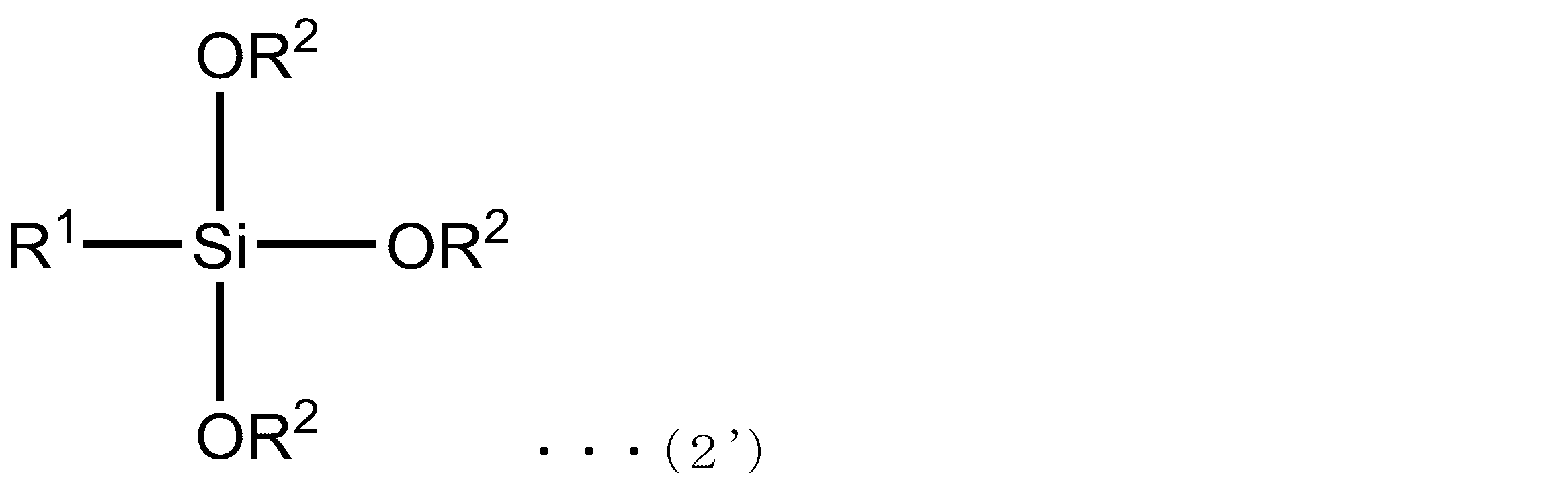
Specific examples of the silicon compound represented by the formula (2) include a compound represented by the following formula (2 ′) in which X is 3. In the following formula (2 ′), R 1 and R 2 are the same as those in the formula (2), respectively. When R 1 and R 2 are methyl groups, the silicon compound is trimethoxy (methyl) silane (hereinafter also referred to as “MTMS”).
本発明のゲル粉砕物含有液において、前記溶媒における前記多孔体ゲルの粉砕物の濃度は、特に制限されず、例えば、0.3~50%(v/v)、0.5~30%(v/v)、1.0~10%(v/v)である。前記粉砕物の濃度が高すぎると、例えば、前記ゲル粉砕物含有液の流動性が著しく低下し、塗工時の凝集物・塗工スジを発生させる可能性がある。一方で、前記粉砕物の濃度が低すぎると、例えば、溶媒の乾燥に相当の時間がかかるだけでなく、乾燥直後の残留溶媒も高くなるために、空隙率が低下してしまう可能性がある。
In the gel pulverized product-containing liquid of the present invention, the concentration of the pulverized product of the porous gel in the solvent is not particularly limited, and is, for example, 0.3 to 50% (v / v), 0.5 to 30% ( v / v), 1.0 to 10% (v / v). When the concentration of the pulverized product is too high, for example, the fluidity of the gel pulverized product-containing liquid is remarkably lowered, and there is a possibility of generating aggregates and coating streaks during coating. On the other hand, if the concentration of the pulverized product is too low, for example, not only does it take a considerable time to dry the solvent, but also the residual solvent immediately after drying increases, so the porosity may decrease. .
本発明のゲル粉砕物含有液の物性は、特に制限されない。前記ゲル粉砕物含有液のせん断粘度は、例えば、10001/sのせん断速度において、例えば、1mPa・s~1Pa・s、1mPa・s~500mPa・s、1mPa・s~50mPa・s、1mPa・s~30mPa・s、1mPa・s~10mPa・s、10mPa・s~1Pa・s、10mPa・s~500mPa・s、10mPa・s~50mPa・s、10mPa・s~30mPa・s、30mPa・s~1Pa・s、30mPa・s~500mPa・s、30mPa・s~50mPa・s、50mPa・s~1Pa・s、50mPa・s~500mPa・s、または500mPa・s~1Pa・sの範囲である。前記せん断粘度が高すぎると、例えば、塗工スジが発生し、グラビア塗工の転写率の低下等の不具合が見られる可能性がある。逆に、せん断粘度が低すぎる場合は、例えば、塗工時のウェット塗布厚みを厚くすることができず、乾燥後に所望の厚みが得られない可能性がある。
The physical properties of the gel pulverized product-containing liquid of the present invention are not particularly limited. The shear viscosity of the gel pulverized product-containing liquid is, for example, 1 mPa · s to 1 Pa · s, 1 mPa · s to 500 mPa · s, 1 mPa · s to 50 mPa · s, 1 mPa · s at a shear rate of 10001 / s. Up to 30 mPa · s, 1 mPa · s to 10 mPa · s, 10 mPa · s to 1 Pa · s, 10 mPa · s to 500 mPa · s, 10 mPa · s to 50 mPa · s, 10 mPa · s to 30 mPa · s, 30 mPa · s to 1 Pa S, 30 mPa · s to 500 mPa · s, 30 mPa · s to 50 mPa · s, 50 mPa · s to 1 Pa · s, 50 mPa · s to 500 mPa · s, or 500 mPa · s to 1 Pa · s. If the shear viscosity is too high, for example, coating streaks may occur, and defects such as a decrease in the transfer rate of gravure coating may be observed. On the other hand, when the shear viscosity is too low, for example, the wet coating thickness at the time of coating cannot be increased, and a desired thickness may not be obtained after drying.
本発明のゲル粉砕物含有液において、前記溶媒としては、例えば、分散媒等が挙げられる。前記分散媒(以下、「塗工用溶媒」ともいう)は、特に制限されず、例えば、後述するゲル化溶媒および粉砕用溶媒があげられ、好ましくは前記粉砕用溶媒である。前記塗工用溶媒としては、沸点が70℃以上180℃未満であり、かつ、20℃での飽和蒸気圧が15kPa以下である有機溶媒を含む。
In the gel pulverized product-containing liquid of the present invention, examples of the solvent include a dispersion medium. The dispersion medium (hereinafter also referred to as “coating solvent”) is not particularly limited, and examples thereof include a gelling solvent and a grinding solvent described later, and the grinding solvent is preferable. The coating solvent includes an organic solvent having a boiling point of 70 ° C. or higher and lower than 180 ° C. and a saturated vapor pressure at 20 ° C. of 15 kPa or lower.
前記有機溶媒としては、例えば、四塩化炭素、1,2-ジクロロエタン、1,1,2,2-テトラクロロエタン、トリクロロエチレン、イソブチルアルコール、イソプロピルアルコール、イソペンチルアルコール、1-ペンチルアルコール(ペンタノール)、エチルアルコール(エタノール)、エチレングリコールモノエチルエーテル、エチレングリコールモノエチルエーテルアセテート、エチレングリコールモノ-ノルマル-ブチルエーテル、エチレングリコールモノメチルエーテル、キシレン、クレゾール、クロロベンゼン、酢酸イソブチル、酢酸イソプロピル、酢酸イソペンチル、酢酸エチル、酢酸ノルマル-ブチル、酢酸ノルマル-プロピル、酢酸ノルマル-ペンチル、シクロヘキサノール、シクロヘキサノン、1,4-ジオキサン、N,N-ジメチルホルムアミド、スチレン、テトラクロロエチレン、1,1,1-トリクロロエタン、トルエン、1-ブタノール、2-ブタノール、メチルイソブチルケトン、メチルエチルケトン、メチルシクロヘキサノール、メチルシクロヘキサノン、メチル-ノルマル-ブチルケトン、イソペンタノール、等が挙げられる。また、前記分散媒中には、表面張力を低下させるペルフルオロ系界面活性剤やシリコン系界面活性剤等を適量含んでもよい。
Examples of the organic solvent include carbon tetrachloride, 1,2-dichloroethane, 1,1,2,2-tetrachloroethane, trichloroethylene, isobutyl alcohol, isopropyl alcohol, isopentyl alcohol, 1-pentyl alcohol (pentanol), Ethyl alcohol (ethanol), ethylene glycol monoethyl ether, ethylene glycol monoethyl ether acetate, ethylene glycol mono-normal-butyl ether, ethylene glycol monomethyl ether, xylene, cresol, chlorobenzene, isobutyl acetate, isopropyl acetate, isopentyl acetate, ethyl acetate, Normal-butyl acetate, normal-propyl acetate, normal-pentyl acetate, cyclohexanol, cyclohexanone, 1,4-dioxa , N, N-dimethylformamide, styrene, tetrachloroethylene, 1,1,1-trichloroethane, toluene, 1-butanol, 2-butanol, methyl isobutyl ketone, methyl ethyl ketone, methyl cyclohexanol, methyl cyclohexanone, methyl normal butyl ketone, iso And pentanol. The dispersion medium may contain an appropriate amount of a perfluoro-based surfactant, a silicon-based surfactant or the like that lowers the surface tension.
本発明のゲル粉砕物含有液は、例えば、前記分散媒に分散させたゾル状の前記粉砕物であるゾル粒子液等が挙げられる。本発明のゲル粉砕物含有液は、例えば、基材上に塗工・乾燥した後に、後述する結合工程により化学架橋を行うことで、一定レベル以上の膜強度を有する空隙層を、連続成膜することが可能である。なお、本発明における「ゾル」とは、ゲルの三次元構造を粉砕することで、粉砕物(つまり、空隙構造の一部を保持したナノ三次元構造の多孔体ゾルの粒子)が、溶媒中に分散して流動性を示す状態をいう。
The gel pulverized material-containing liquid of the present invention includes, for example, a sol particle liquid that is the sol-like pulverized material dispersed in the dispersion medium. The gel pulverized product-containing liquid of the present invention, for example, continuously forms a void layer having a film strength of a certain level or more by performing chemical crosslinking by a bonding step described later after coating and drying on a substrate. Is possible. In the present invention, “sol” means that a three-dimensional structure of a gel is pulverized so that a pulverized product (that is, a nano-three-dimensional porous sol particle retaining a part of a void structure) is dissolved in a solvent. The state which disperse | distributes to and shows fluidity.
本発明のゲル粉砕物含有液は、例えば、前記ゲルの粉砕物同士を化学的に結合させるための触媒を含んでいても良い。前記触媒の含有率は、特に限定されないが、前記ゲルの粉砕物の重量に対し、例えば、0.01~20重量%、0.05~10重量%、または0.1~5重量%である。
The gel pulverized product-containing liquid of the present invention may contain, for example, a catalyst for chemically bonding the gel pulverized products. The content of the catalyst is not particularly limited, and is, for example, 0.01 to 20% by weight, 0.05 to 10% by weight, or 0.1 to 5% by weight with respect to the weight of the pulverized product of the gel. .
また、本発明のゲル粉砕物含有液は、例えば、さらに、前記ゲルの粉砕物同士を間接的に結合させるための架橋補助剤を含んでいても良い。前記架橋補助剤の含有率は、特に限定されないが、例えば、前記ゲルの粉砕物の重量に対して0.01~20重量%、0.05~15重量%、または0.1~10重量%である。
The gel pulverized product-containing liquid of the present invention may further contain, for example, a crosslinking aid for indirectly bonding the gel pulverized products. The content of the crosslinking aid is not particularly limited. For example, the content is 0.01 to 20% by weight, 0.05 to 15% by weight, or 0.1 to 10% by weight with respect to the weight of the pulverized gel. It is.
なお、本発明のゲル粉砕物含有液は、前記ゲルの構成単位モノマーの官能基のうち、ゲル内架橋構造に寄与していない官能基の割合が、例えば、30mol%以下、25mol%以下、20mol%以下、15mol%以下であっても良く、例えば、1mol%以上、2mol%以上、3mol%以上、4mol%以上であっても良い。前記ゲル内架橋構造に寄与していない官能基の割合は、例えば、下記のようにして測定することができる。
In the gel pulverized product-containing liquid of the present invention, the proportion of functional groups that do not contribute to the intra-gel cross-linking structure among the functional groups of the constituent monomer of the gel is, for example, 30 mol% or less, 25 mol% or less, 20 mol. % Or less, 15 mol% or less, for example, 1 mol% or more, 2 mol% or more, 3 mol% or more, 4 mol% or more may be sufficient. The ratio of the functional group that does not contribute to the in-gel crosslinked structure can be measured, for example, as follows.
(ゲル内架橋構造に寄与していない官能基の割合の測定方法)
ゲルを乾燥後、固体NMR(Si-NMR)を測定し、NMRのピーク比から架橋構造に寄与していない残存シラノール基(ゲル内架橋構造に寄与していない官能基)の割合を算出する。また、前記官能基がシラノール基以外の場合でも、これに準じて、NMRのピーク比からゲル内架橋構造に寄与していない官能基の割合を算出することができる。 (Measuring method of the proportion of functional groups that do not contribute to the crosslinked structure in the gel)
After drying the gel, solid-state NMR (Si-NMR) is measured, and the ratio of residual silanol groups that do not contribute to the crosslinked structure (functional groups that do not contribute to the in-gel crosslinked structure) is calculated from the peak ratio of NMR. In addition, even when the functional group is other than a silanol group, the proportion of the functional group that does not contribute to the in-gel crosslinked structure can be calculated from the peak ratio of NMR.
以下に、本発明ゲル粉砕物含有液の製造方法を、例を挙げて説明する。本発明のゲル粉砕物含有液は、特に記載しない限り、以下の説明を援用できる。
Hereinafter, a method for producing the gel pulverized product-containing liquid of the present invention will be described with an example. The following explanation can be used for the gel pulverized product-containing liquid of the present invention unless otherwise specified.
本発明のゲル粉砕物含有液の製造方法において、混合工程は、前記多孔体ゲルの粒子(粉砕物)と前記溶媒とを混合する工程であり、あってもよいし、なくてもよい。前記混合工程の具体例としては、例えば、少なくとも3官能以下の飽和結合官能基を含むケイ素化合物から得られたゲル状のケイ素化合物(ケイ素化合物ゲル)の粉砕物と分散媒とを混合する工程が挙げられる。本発明において、前記多孔体ゲルの粉砕物は、後述するゲル粉砕工程により、前記多孔体ゲルから得ることができる。また、前記多孔体ゲルの粉砕物は、例えば、後述する熟成工程を施した熟成処理後の前記多孔体ゲルから得ることができる。
In the method for producing a gel pulverized product-containing liquid of the present invention, the mixing step is a step of mixing the porous gel particles (pulverized product) and the solvent, and may or may not be performed. As a specific example of the mixing step, for example, there is a step of mixing a pulverized product of a gel-like silicon compound (silicon compound gel) obtained from a silicon compound containing at least a trifunctional or lower saturated bond functional group and a dispersion medium. Can be mentioned. In the present invention, the pulverized product of the porous gel can be obtained from the porous gel by a gel pulverization step described later. Moreover, the pulverized product of the porous gel can be obtained, for example, from the porous gel after the aging treatment in which the aging step described later is performed.
本発明のゲル粉砕物含有液の製造方法において、ゲル化工程は、例えば、塊状の多孔体を溶媒中でゲル化して前記多孔体ゲルとする工程であり、前記ゲル化工程の具体例としては、例えば、前記少なくとも3官能以下の飽和結合官能基を含むケイ素化合物を溶媒中でゲル化して、ケイ素化合物ゲルを生成する工程である。
In the method for producing a gel pulverized product-containing liquid of the present invention, the gelation step is, for example, a step of gelling a massive porous body in a solvent to form the porous body gel. As a specific example of the gelation step, For example, it is a step of producing a silicon compound gel by gelling a silicon compound containing at least a trifunctional or lower functional saturated bond functional group in a solvent.
以下では、前記ゲル化工程を、前記多孔体が、ケイ素化合物である場合を例にとって説明する。
Hereinafter, the gelation step will be described by taking the case where the porous body is a silicon compound as an example.
前記ゲル化工程は、例えば、モノマーの前記ケイ素化合物を、脱水縮合触媒の存在下、脱水縮合反応によりゲル化する工程であり、これによって、ケイ素化合物ゲルが得られる。前記ケイ素化合物ゲルは、例えば、残留シラノール基を有し、前記残留シラノール基は、後述する前記ケイ素化合物ゲルの粉砕物同士の化学的な結合に応じて、適宜、調整することが好ましい。
The gelation step is, for example, a step of gelling the monomer silicon compound by a dehydration condensation reaction in the presence of a dehydration condensation catalyst, whereby a silicon compound gel is obtained. The silicon compound gel has, for example, residual silanol groups, and the residual silanol groups are preferably adjusted as appropriate according to chemical bonding between the pulverized products of the silicon compound gel described later.
前記ゲル化工程において、前記ケイ素化合物は、特に制限されず、脱水縮合反応によりゲル化するものであればよい。前記脱水縮合により、例えば、前記ケイ素化合物間が結合される。前記ケイ素化合物間の結合は、例えば、水素結合または分子間力結合である。
In the gelation step, the silicon compound is not particularly limited as long as it is gelled by a dehydration condensation reaction. By the dehydration condensation, for example, the silicon compounds are bonded. The bond between the silicon compounds is, for example, a hydrogen bond or an intermolecular force bond.
前記ケイ素化合物は、例えば、下記式(1)で表されるケイ素化合物が挙げられる。前記式(1)のケイ素化合物は、水酸基を有するため、前記式(1)のケイ素化合物間は、例えば、それぞれの水酸基を介して、水素結合または分子間力結合が可能である。
Examples of the silicon compound include a silicon compound represented by the following formula (1). Since the silicon compound of the formula (1) has a hydroxyl group, the silicon compound of the formula (1) can be hydrogen bonded or intermolecularly bonded through, for example, each hydroxyl group.

前記式(1)中、例えば、Xは、2、3または4であり、R1は、直鎖もしくは分枝アルキル基、である。前記R1の炭素数は、例えば、1~6、1~4、1~2である。前記直鎖アルキル基は、例えば、メチル基、エチル基、プロピル基、ブチル基、ペンチル基、ヘキシル基等が挙げられ、前記分枝アルキル基は、例えば、イソプロピル基、イソブチル基等が挙げられる。前記Xは、例えば、3または4である。
In the formula (1), for example, X is 2, 3 or 4, and R 1 is a linear or branched alkyl group. The carbon number of R 1 is, for example, 1-6, 1-4, 1-2. Examples of the linear alkyl group include a methyl group, an ethyl group, a propyl group, a butyl group, a pentyl group, and a hexyl group. Examples of the branched alkyl group include an isopropyl group and an isobutyl group. X is, for example, 3 or 4.
前記式(1)で表されるケイ素化合物の具体例としては、例えば、Xが3である下記式(1’)に示す化合物が挙げられる。下記式(1’)において、R1は、前記式(1)と同様であり、例えば、メチル基である。R1がメチル基の場合、前記ケイ素化合物は、トリス(ヒドロキシ)メチルシランである。前記Xが3の場合、前記ケイ素化合物は、例えば、3つの官能基を有する3官能シランである。
Specific examples of the silicon compound represented by the formula (1) include a compound represented by the following formula (1 ′) in which X is 3. In the following formula (1 ′), R 1 is the same as in the above formula (1), and is, for example, a methyl group. When R 1 is a methyl group, the silicon compound is tris (hydroxy) methylsilane. When X is 3, the silicon compound is, for example, a trifunctional silane having three functional groups.

また、前記式(1)で表されるケイ素化合物の具体例としては、例えば、Xが4である化合物が挙げられる。この場合、前記ケイ素化合物は、例えば、4つの官能基を有する4官能シランである。
Further, specific examples of the silicon compound represented by the formula (1) include a compound in which X is 4. In this case, the silicon compound is, for example, a tetrafunctional silane having four functional groups.
前記ケイ素化合物は、例えば、加水分解により前記式(1)のケイ素化合物を形成する前駆体でもよい。前記前駆体としては、例えば、加水分解により前記ケイ素化合物を生成できるものであればよく、具体例として、前記式(2)で表される化合物が挙げられる。
The silicon compound may be, for example, a precursor that forms the silicon compound of the formula (1) by hydrolysis. The precursor is not particularly limited as long as it can generate the silicon compound by hydrolysis, and specific examples thereof include a compound represented by the formula (2).
前記ケイ素化合物が前記式(2)で表される前駆体の場合、本発明の製造方法は、例えば、前記ゲル化工程に先立って、前記前駆体を加水分解する工程を含んでもよい。
When the silicon compound is a precursor represented by the formula (2), the production method of the present invention may include, for example, a step of hydrolyzing the precursor prior to the gelation step.
前記加水分解の方法は、特に制限されず、例えば、触媒存在下での化学反応により行うことができる。前記触媒としては、例えば、シュウ酸、酢酸等の酸等が挙げられる。前記加水分解反応は、例えば、シュウ酸の水溶液を、前記ケイ素化合物前駆体のジメチルスルホキシド溶液に、室温環境下でゆっくり滴下混合させた後に、そのまま30分程度撹拌することで行うことができる。前記ケイ素化合物前駆体を加水分解する際は、例えば、前記ケイ素化合物前駆体のアルコキシ基を完全に加水分解することで、その後のゲル化・熟成・空隙構造形成後の加熱・固定化を、さらに効率良く発現することができる。
The hydrolysis method is not particularly limited, and can be performed, for example, by a chemical reaction in the presence of a catalyst. Examples of the catalyst include acids such as oxalic acid and acetic acid. The hydrolysis reaction can be performed, for example, by slowly dropping an aqueous solution of oxalic acid into the dimethyl sulfoxide solution of the silicon compound precursor in a room temperature environment and then stirring the mixture for about 30 minutes. When hydrolyzing the silicon compound precursor, for example, by completely hydrolyzing the alkoxy group of the silicon compound precursor, further heating and immobilization after gelation / aging / void structure formation, It can be expressed efficiently.
本発明において、前記ケイ素化合物は、例えば、トリメトキシ(メチル)シランの加水分解物が例示できる。
In the present invention, examples of the silicon compound include a hydrolyzate of trimethoxy (methyl) silane.
前記モノマーのケイ素化合物は、特に制限されず、例えば、製造する機能性多孔体の用途に応じて、適宜選択できる。前記機能性多孔体の製造において、前記ケイ素化合物は、例えば、低屈折率性を重視する場合、低屈折率性に優れる点から、前記3官能シランが好ましく、また、強度(例えば、耐擦傷性)を重視する場合は、耐擦傷性に優れる点から、前記4官能シランが好ましい。また、前記ケイ素化合物ゲルの原料となる前記ケイ素化合物は、例えば、一種類のみを使用してもよいし、二種類以上を併用してもよい。具体例として、前記ケイ素化合物として、例えば、前記3官能シランのみを含んでもよいし、前記4官能シランのみを含んでもよいし、前記3官能シランと前記4官能シランの両方を含んでもよいし、さらに、その他のケイ素化合物を含んでもよい。前記ケイ素化合物として、二種類以上のケイ素化合物を使用する場合、その比率は、特に制限されず、適宜設定できる。
The silicon compound of the monomer is not particularly limited, and can be appropriately selected according to the use of the functional porous body to be produced, for example. In the production of the functional porous body, for example, when the low refractive index property is important, the silicon compound is preferably the trifunctional silane from the viewpoint of excellent low refractive index property, and also has strength (for example, scratch resistance). ) Is preferred, the tetrafunctional silane is preferable from the viewpoint of excellent scratch resistance. Moreover, the said silicon compound used as the raw material of the said silicon compound gel may use only 1 type, for example, and may use 2 or more types together. As a specific example, the silicon compound may include, for example, only the trifunctional silane, may include only the tetrafunctional silane, may include both the trifunctional silane and the tetrafunctional silane, Furthermore, other silicon compounds may be included. When two or more types of silicon compounds are used as the silicon compound, the ratio is not particularly limited and can be set as appropriate.
前記ケイ素化合物等の多孔体のゲル化は、例えば、前記多孔体間の脱水縮合反応により行うことができる。前記脱水縮合反応は、例えば、触媒存在下で行うことが好ましく、前記触媒としては、例えば、塩酸、シュウ酸、硫酸等の酸触媒、およびアンモニア、水酸化カリウム、水酸化ナトリウム、水酸化アンモニウム等の塩基触媒等の、脱水縮合触媒が挙げられる。前記脱水縮合触媒は、酸触媒でも塩基触媒でも良いが、塩基触媒が好ましい。前記脱水縮合反応において、前記多孔体に対する前記触媒の添加量は、特に制限されず、前記多孔体1モルに対して、触媒は、例えば、0.01~10モル、0.05~7モル、0.1~5モルである。
The gelation of the porous body such as the silicon compound can be performed, for example, by a dehydration condensation reaction between the porous bodies. The dehydration condensation reaction is preferably performed, for example, in the presence of a catalyst. Examples of the catalyst include acid catalysts such as hydrochloric acid, oxalic acid, and sulfuric acid, and ammonia, potassium hydroxide, sodium hydroxide, ammonium hydroxide, and the like. And a dehydration condensation catalyst such as a base catalyst. The dehydration condensation catalyst may be an acid catalyst or a base catalyst, but a base catalyst is preferred. In the dehydration condensation reaction, the amount of the catalyst added to the porous body is not particularly limited, and for example, 0.01 to 10 mol, 0.05 to 7 mol, 0.1 to 5 moles.
前記ケイ素化合物等の多孔体のゲル化は、例えば、溶媒中で行うことが好ましい。前記溶媒における前記多孔体の割合は、特に制限されない。前記溶媒は、例えば、ジメチルスルホキシド(DMSO)、N-メチルピロリドン(NMP)、N,N-ジメチルアセトアミド(DMAc)、ジメチルホルムアミド(DMF)、γ-ブチルラクトン(GBL)、アセトニトリル(MeCN)、エチレングリコールエチルエーテル(EGEE)等が挙げられる。前記溶媒は、例えば、1種類でもよいし、2種類以上を併用してもよい。前記ゲル化に使用する溶媒を、以下、「ゲル化用溶媒」ともいう。
The gelation of the porous body such as the silicon compound is preferably performed in a solvent, for example. The ratio of the porous body in the solvent is not particularly limited. Examples of the solvent include dimethyl sulfoxide (DMSO), N-methylpyrrolidone (NMP), N, N-dimethylacetamide (DMAc), dimethylformamide (DMF), γ-butyllactone (GBL), acetonitrile (MeCN), ethylene Examples thereof include glycol ethyl ether (EGEE). For example, one type of solvent may be used, or two or more types may be used in combination. Hereinafter, the solvent used for the gelation is also referred to as “gelling solvent”.
前記ゲル化の条件は、特に制限されない。前記多孔体を含む前記溶媒に対する処理温度は、例えば、20~30℃、22~28℃、24~26℃であり、処理時間は、例えば、1~60分、5~40分、10~30分である。前記脱水縮合反応を行う場合、その処理条件は、特に制限されず、これらの例示を援用できる。前記ゲル化を行うことで、前記多孔体がケイ素化合物である場合、例えば、シロキサン結合が成長し、前記ケイ素化合物の一次粒子が形成され、さらに反応が進行することで、前記一次粒子同士が、数珠状に連なり三次元構造のゲルが生成される。
The gelation conditions are not particularly limited. The treatment temperature for the solvent containing the porous body is, for example, 20 to 30 ° C., 22 to 28 ° C., 24 to 26 ° C., and the treatment time is, for example, 1 to 60 minutes, 5 to 40 minutes, 10 to 30 Minutes. When performing the said dehydration condensation reaction, the process conditions in particular are not restrict | limited, These illustrations can be used. By performing the gelation, when the porous body is a silicon compound, for example, a siloxane bond grows, primary particles of the silicon compound are formed, and further the reaction proceeds, so that the primary particles are A gel with a three-dimensional structure is formed in a bead shape.
前記ゲル化工程において得られる前記多孔体のゲル形態は、特に制限されない。「ゲル」とは、一般に、溶質が、相互作用のために独立した運動性を失って集合した構造をもち、固化した状態をいう。また、ゲルの中でも、一般に、ウェットゲルは、分散媒を含み、分散媒中で溶質が一様な構造をとるものをいい、キセロゲルは、溶媒が除去されて、溶質が、空隙を持つ網目構造をとるものをいう。本発明において、前記ケイ素化合物ゲルは、例えば、ウェットゲルを用いることが好ましい。前記多孔体ゲルがケイ素化合物ゲルである場合、前記ケイ素化合物ゲルの残量シラノール基は、特に制限されず、例えば、後述する範囲が同様に例示できる。
The gel form of the porous body obtained in the gelation step is not particularly limited. “Gel” generally refers to a solidified state in which a solute has a structure in which it loses independent motility due to interaction and aggregates. In addition, among gels, generally, a wet gel includes a dispersion medium and a solute has a uniform structure in the dispersion medium. A xerogel is a network structure in which the solvent is removed and the solute has voids. The one that takes In the present invention, the silicon compound gel is preferably a wet gel, for example. When the porous gel is a silicon compound gel, the remaining silanol group of the silicon compound gel is not particularly limited, and examples thereof include the ranges described later.
前記ゲル化により得られた前記多孔体ゲルは、例えば、このまま前記溶媒置換工程および前記第1の粉砕段階に供してもよいが、前記第1の粉砕段階に先立ち、前記熟成工程において熟成処理を施してもよい。前記熟成工程は、ゲル化した前記多孔体(多孔体ゲル)を溶媒中で熟成する。前記熟成工程において、前記熟成処理の条件は、特に制限されず、例えば、前記多孔体ゲルを、溶媒中、所定温度でインキュベートすればよい。前記熟成処理によれば、例えば、ゲル化で得られた三次元構造を有する多孔体ゲルについて、前記一次粒子をさらに成長させることができ、これによって前記粒子自体のサイズを大きくすることが可能である。そして、結果的に、前記粒子同士が接触しているネック部分の接触状態を、例えば、点接触から面接触に増やすことができる。上記のような熟成処理を行った多孔体ゲルは、例えば、ゲル自体の強度が増加し、結果的には、粉砕を行った後の前記粉砕物の三次元基本構造の強度をより向上できる。これにより、前記本発明のゲル粉砕物含有液を用いて塗工膜を形成した場合、例えば、塗工後の乾燥工程においても、前記三次元基本構造が堆積した空隙構造の細孔サイズが、前記乾燥工程において生じる前記塗工膜中の溶媒の揮発に伴って、収縮することを抑制できる。
The porous gel obtained by the gelation may be subjected, for example, to the solvent replacement step and the first pulverization step as it is, but prior to the first pulverization step, an aging treatment is performed in the aging step. You may give it. In the aging step, the gelled porous body (porous gel) is aged in a solvent. In the aging step, conditions for the aging treatment are not particularly limited, and for example, the porous gel may be incubated in a solvent at a predetermined temperature. According to the aging treatment, for example, the porous particles having a three-dimensional structure obtained by gelation can further grow the primary particles, thereby increasing the size of the particles themselves. is there. As a result, the contact state of the neck portion where the particles are in contact can be increased from point contact to surface contact, for example. The porous gel subjected to the aging treatment as described above, for example, increases the strength of the gel itself, and as a result, the strength of the three-dimensional basic structure of the pulverized product after pulverization can be further improved. Thereby, when forming a coating film using the gel pulverized product-containing liquid of the present invention, for example, in the drying step after coating, the pore size of the void structure in which the three-dimensional basic structure is deposited, It can suppress shrinking | contraction with the volatilization of the solvent in the said coating film which arises in the said drying process.
前記熟成処理の温度は、その下限が、例えば、30℃以上、35℃以上、40℃以上であり、その上限が、例えば、80℃以下、75℃以下、70℃以下であり、その範囲が、例えば、30~80℃、35~75℃、40~70℃である。前記所定の時間は、特に制限されず、その下限が、例えば、5時間以上、10時間以上、15時間以上であり、その上限が、例えば、50時間以下、40時間以下、30時間以下であり、その範囲が、例えば、5~50時間、10~40時間、15~30時間である。なお、熟成の最適な条件については、例えば、前述したように、前記多孔体ゲルにおける、前記一次粒子のサイズの増大、および前記ネック部分の接触面積の増大が得られる条件に設定することが好ましい。また、前記熟成工程において、前記熟成処理の温度は、例えば、使用する溶媒の沸点を考慮することが好ましい。前記熟成処理は、例えば、熟成温度が高すぎると、前記溶媒が過剰に揮発してしまい、前記塗工液の濃縮により、三次元空隙構造の細孔が閉口する等の不具合が生じる可能性がある。一方で、前記熟成処理は、例えば、熟成温度が低すぎると、前記熟成による効果が十分に得られず、量産プロセスの経時での温度バラツキが増大することとなり、品質に劣る製品ができる可能性がある。
The lower limit of the temperature of the aging treatment is, for example, 30 ° C. or more, 35 ° C. or more, 40 ° C. or more, and the upper limit thereof is, for example, 80 ° C. or less, 75 ° C. or less, 70 ° C. or less. For example, 30 to 80 ° C, 35 to 75 ° C, 40 to 70 ° C. The predetermined time is not particularly limited, and the lower limit thereof is, for example, 5 hours or more, 10 hours or more, 15 hours or more, and the upper limit thereof is, for example, 50 hours or less, 40 hours or less, 30 hours or less. The range is, for example, 5 to 50 hours, 10 to 40 hours, 15 to 30 hours. The optimum conditions for aging are preferably set, for example, as described above, so that an increase in the size of the primary particles and an increase in the contact area of the neck portion can be obtained in the porous gel. . In the aging step, the temperature of the aging treatment preferably takes into account, for example, the boiling point of the solvent used. In the aging treatment, for example, if the aging temperature is too high, the solvent is excessively volatilized, and there is a possibility that problems such as closing of the pores of the three-dimensional void structure occur due to the concentration of the coating solution. is there. On the other hand, in the aging treatment, for example, if the aging temperature is too low, the effect due to the aging is not sufficiently obtained, temperature variation with time of the mass production process increases, and a product with poor quality may be produced. There is.
前記熟成処理は、例えば、前記ゲル化工程と同じ溶媒を使用でき、具体的には、前記ゲル処理後の反応物(つまり、前記多孔体ゲルを含む前記溶媒)に対して、そのまま施すことが好ましい。前記多孔体ゲルが、前記ケイ素化合物ゲルである場合、ゲル化後の熟成処理を終えた前記ケイ素化合物ゲルに含まれる残留シラノール基のモル数は、例えば、ゲル化に使用した原材料(例えば、前記ケイ素化合物またはその前駆体)のアルコキシ基のモル数を100とした場合の残留シラノール基の割合であり、その下限が、例えば、50%以上、40%以上、30%以上であり、その上限が、例えば、1%以下、3%以下、5%以下であり、その範囲が、例えば、1~50%、3~40%、5~30%である。前記ケイ素化合物ゲルの硬度を上げる目的では、例えば、残留シラノール基のモル数が低いほど好ましい。残留シラノール基のモル数が高すぎると、例えば、前記機能性多孔体の形成において、前記機能性多孔体の前駆体が架橋されるまでに、空隙構造を保持できなくなる可能性がある。一方で、残留シラノール基のモル数が低すぎると、例えば、前記結合工程において、前記機能性多孔体の前駆体を架橋できなくなり、十分な膜強度を付与できなくなる可能性がある。なお、上記は、残留シラノール基の例であるが、例えば、前記ケイ素化合物ゲルの原材料として、前記ケイ素化合物を各種反応性官能基で修飾したものを使用する場合は、各々の官能基に対しても、同様の現象を適用できる。
In the aging treatment, for example, the same solvent as in the gelation step can be used, and specifically, the reaction product after the gel treatment (that is, the solvent containing the porous gel) may be applied as it is. preferable. When the porous gel is the silicon compound gel, the number of moles of residual silanol groups contained in the silicon compound gel after the aging treatment after gelation is, for example, the raw material used for the gelation (for example, the above-mentioned Silicon compound or precursor thereof) is the ratio of residual silanol groups when the number of moles of alkoxy groups is 100, and the lower limit is, for example, 50% or more, 40% or more, 30% or more, and the upper limit is For example, it is 1% or less, 3% or less, 5% or less, and the range is, for example, 1 to 50%, 3 to 40%, or 5 to 30%. For the purpose of increasing the hardness of the silicon compound gel, for example, the lower the number of moles of residual silanol groups, the better. When the number of residual silanol groups is too high, for example, in the formation of the functional porous body, there is a possibility that the void structure cannot be maintained before the functional porous body precursor is crosslinked. On the other hand, if the number of moles of residual silanol groups is too low, for example, in the bonding step, the precursor of the functional porous body cannot be crosslinked, and sufficient film strength may not be imparted. The above is an example of residual silanol groups. For example, when using the silicon compound modified with various reactive functional groups as a raw material of the silicon compound gel, The same phenomenon can be applied.
前記ゲル化により得られた前記多孔体ゲルは、例えば、前記熟成工程において熟成処理を施した後、溶媒置換工程を施し、さらにその後、前記ゲル粉砕工程に供する。前記溶媒置換工程は、前記溶媒を他の溶媒に置換する。
The porous gel obtained by the gelation is subjected to, for example, a aging treatment in the aging step, a solvent replacement step, and then subjected to the gel pulverization step. In the solvent replacement step, the solvent is replaced with another solvent.
本発明において、前記ゲル粉砕工程は、前述のように、前記多孔体ゲルを粉砕する工程である。前記粉砕は、例えば、前記ゲル化工程後の前記多孔体ゲルに施してもよいし、さらに、前記熟成処理を施した前記熟成後の多孔体ゲルに施してもよい。
In the present invention, the gel crushing step is a step of crushing the porous gel as described above. The pulverization may be performed, for example, on the porous gel after the gelation step, or may be performed on the post-ripening porous gel that has been subjected to the aging treatment.
また、前述のとおり、前記溶媒置換工程に先立ち(例えば、前記熟成工程後に)、前記ゲルの形状および大きさを制御するゲル形態制御工程を行っても良い。前記ゲル形態制御工程において制御する前記ゲルの形状および大きさは、特に限定されないが、例えば、前述のとおりである。前記ゲル形態制御工程は、例えば、前記ゲルを、適切な大きさおよび形状の立体(3次元体)に分割する(例えば、切り分ける)ことにより行っても良い。
As described above, a gel form control step for controlling the shape and size of the gel may be performed prior to the solvent replacement step (for example, after the aging step). The shape and size of the gel controlled in the gel form control step are not particularly limited, but are as described above, for example. The gel form control step may be performed, for example, by dividing (for example, cutting) the gel into a solid (three-dimensional body) having an appropriate size and shape.
さらに、前述のとおり、前記ゲルに前記溶媒置換工程を施してから前記ゲル粉砕工程を行なう。前記溶媒置換工程は、前記溶媒を他の溶媒に置換する。前記溶媒を前記他の溶媒に置換しないと、例えば、ゲル化工程で使用した触媒および溶媒が、前記熟成工程後も残存することで、さらに経時にゲル化が生じて最終的に得られるゲル粉砕物含有液のポットライフに影響するおそれ、前記ゲル粉砕物含有液を用いて形成した塗工膜を乾燥した際の乾燥効率が低下するおそれ等があるためである。なお、前記ゲル粉砕工程における前記他の溶媒を、以下、「粉砕用溶媒」ともいう。
Further, as described above, the gel pulverization step is performed after the solvent substitution step is performed on the gel. In the solvent replacement step, the solvent is replaced with another solvent. If the solvent is not replaced with the other solvent, for example, the catalyst and the solvent used in the gelation step remain after the aging step, and further gelation occurs over time, resulting in gel pulverization finally obtained This is because the pot life of the product-containing liquid may be affected, and the drying efficiency when the coating film formed using the gel pulverized product-containing liquid is dried may be decreased. Hereinafter, the other solvent in the gel pulverization step is also referred to as a “grinding solvent”.
前記粉砕用溶媒(他の溶媒)は、特に制限されず、例えば、有機溶媒が使用できる。前記有機溶媒は、例えば、沸点140℃以下、130℃以下、沸点100℃以下、沸点85℃以下の溶媒が挙げられる。具体例としては、例えば、イソプロピルアルコール(IPA)、エタノール、メタノール、n-ブタノール、2-ブタノール、イソブチルアルコール、ペンチルアルコール、プロピレングリコールモノメチルエーテル(PGME)、メチルセロソルブ、アセトン等が挙げられる。前記粉砕用溶媒は、例えば、1種類でもよいし、2種類以上の併用でもよい。
The solvent for pulverization (other solvent) is not particularly limited, and for example, an organic solvent can be used. Examples of the organic solvent include solvents having a boiling point of 140 ° C. or lower, 130 ° C. or lower, a boiling point of 100 ° C. or lower, and a boiling point of 85 ° C. or lower. Specific examples include isopropyl alcohol (IPA), ethanol, methanol, n-butanol, 2-butanol, isobutyl alcohol, pentyl alcohol, propylene glycol monomethyl ether (PGME), methyl cellosolve, acetone and the like. The pulverizing solvent may be, for example, one type or a combination of two or more types.
また、前記粉砕用溶媒の極性が低い場合等は、例えば、前記溶媒置換工程を複数の溶媒置換段階に分けて行ない、前記溶媒置換段階において、後に行う段階の方が、先に行う段階よりも、前記他の溶媒の親水性が低くなるようにしても良い。このようにすることで、例えば、溶媒置換効率を向上させ、前記ゲル中のゲル製造用溶媒(例えばDMSO)の残存量をきわめて低くすることも可能である。具体例として、例えば、前記溶媒置換工程を3段階の溶媒置換段階に分けて行ない、第1の溶媒置換段階で、ゲル中のDMSOをまず水に置換し、つぎに、第2の溶媒置換段階で、ゲル中の前記水をIPAに置換し、さらに、第3の置換段階で、ゲル中の前記IPAをイソブチルアルコールに置換しても良い。
Further, when the polarity of the pulverizing solvent is low, for example, the solvent replacement step is divided into a plurality of solvent replacement steps. In the solvent replacement step, the step performed later is more than the step performed earlier. The hydrophilicity of the other solvent may be lowered. In this way, for example, the solvent replacement efficiency can be improved, and the residual amount of the gel production solvent (for example, DMSO) in the gel can be made extremely low. As a specific example, for example, the solvent replacement step is divided into three solvent replacement steps. In the first solvent replacement step, DMSO in the gel is first replaced with water, and then the second solvent replacement step. Then, the water in the gel may be replaced with IPA, and the IPA in the gel may be replaced with isobutyl alcohol in the third replacement step.
前記ゲル化用溶媒と前記粉砕用溶媒との組合せは、特に制限されず、例えば、DMSOとIPAとの組合せ、DMSOとエタノールとの組合せ、DMSOとイソブチルアルコールとの組合せ、DMSOとn-ブタノールとの組合せ等が挙げられる。このように、前記ゲル化用溶媒を前記破砕用溶媒に置換することで、例えば、後述する塗膜形成において、より均一な塗工膜を形成することができる。
The combination of the gelling solvent and the grinding solvent is not particularly limited. For example, a combination of DMSO and IPA, a combination of DMSO and ethanol, a combination of DMSO and isobutyl alcohol, DMSO and n-butanol and the like. And the like. Thus, by replacing the gelling solvent with the crushing solvent, for example, a more uniform coating film can be formed in the coating film formation described below.
前記溶媒置換工程は、特に限定されないが、例えば、以下のようにして行うことができる。すなわち、まず、前記ゲル製造工程により製造したゲル(例えば、前記熟成処理後のゲル)を、前記他の溶媒に浸漬もしくは接触させ、前記ゲル中のゲル製造用触媒、縮合反応で生成したアルコール成分、水等を、前記他の溶媒中に溶解させる。その後、前記ゲルを浸漬もしくは接触させた溶媒を捨てて、新たな溶媒に再度前記ゲルを浸漬もしくは接触させる。これを、前記ゲル中のゲル製造用溶媒の残存量が、所望の量となるまで繰り返す。1回あたりの浸漬時間は、例えば0.5時間以上、1時間以上、または1.5時間以上であり、上限値は特に限定されないが、例えば10時間以下である。また上記溶媒の浸漬は前記溶媒のゲルへの連続的な接触で対応してもよい。また、前記浸漬中の温度は特に限定されないが、例えば20~70℃、25~65℃、または30~60℃であっても良い。加熱を行なうと溶媒置換が早く進行し、置換させるのに必要な溶媒量が少なくて済むが、室温で簡便に溶媒置換を行なってもよい。また、例えば、前記溶媒置換工程を複数の溶媒置換段階に分けて行なう場合は、前記複数の溶媒置換段階のそれぞれを、前述のようにして行っても良い。
The solvent replacement step is not particularly limited, but can be performed as follows, for example. That is, first, the gel produced by the gel production process (for example, the gel after the aging treatment) is immersed or brought into contact with the other solvent, the gel production catalyst in the gel, and the alcohol component produced by the condensation reaction. , Water and the like are dissolved in the other solvent. Thereafter, the solvent in which the gel is immersed or contacted is discarded, and the gel is immersed or contacted again in a new solvent. This is repeated until the residual amount of the solvent for gel production in the gel reaches a desired amount. The immersion time per time is, for example, 0.5 hours or more, 1 hour or more, or 1.5 hours or more, and the upper limit is not particularly limited, but is, for example, 10 hours or less. The immersion of the solvent may be handled by continuous contact of the solvent with the gel. Further, the temperature during the immersion is not particularly limited, but may be, for example, 20 to 70 ° C, 25 to 65 ° C, or 30 to 60 ° C. When heating is performed, the solvent replacement proceeds quickly, and the amount of solvent necessary for the replacement may be small. However, the solvent replacement may be simply performed at room temperature. For example, when the solvent replacement step is performed in a plurality of solvent replacement steps, each of the plurality of solvent replacement steps may be performed as described above.
また、例えば、前記溶媒置換工程を、複数の溶媒置換段階に分けて行い、後に行う段階の方が、先に行う段階よりも、前記他の溶媒の親水性が低いようにしてもよい。このように、置換用溶媒(前記他の溶媒)を、親水性が高い溶媒から徐々に親水性が低い(疎水性が高い)溶媒に変えることで、ゲル中のゲル製造用溶媒の残存量をきわめて少なくすることができる。このようにすれば、例えば、さらに空隙率が高い(したがって、例えば低屈折率の)空隙層を製造することが可能である。
Also, for example, the solvent replacement step may be performed by dividing it into a plurality of solvent replacement steps, and the step performed later may have a lower hydrophilicity than the step performed earlier. In this way, by changing the substitution solvent (the other solvent) from a solvent having high hydrophilicity to a solvent having gradually low hydrophilicity (high hydrophobicity), the remaining amount of the solvent for gel production in the gel is reduced. It can be very little. In this way, for example, it is possible to produce a void layer having a higher porosity (and thus a low refractive index, for example).
前記溶媒置換工程を行った後における前記ゲル中のゲル製造用溶媒残存量は、好ましくは0.005g/ml以下、さらに好ましくは0.001g/ml以下、特に好ましくは0.0005g/ml以下である。前記ゲル中のゲル製造用溶媒残存量の残存量の下限値は、特に限定されないが、例えば、ゼロまたは検出限界値以下もしくは未満である。
The residual amount of the solvent for gel production in the gel after the solvent substitution step is preferably 0.005 g / ml or less, more preferably 0.001 g / ml or less, particularly preferably 0.0005 g / ml or less. is there. The lower limit value of the residual amount of the solvent for gel production in the gel is not particularly limited, but is, for example, zero or less than or less than the detection limit value.
前記溶媒置換工程を行った後における前記ゲル中のゲル製造用溶媒残存量は、例えば、以下のようにして測定することができる。
The amount of residual solvent for gel production in the gel after the solvent replacement step can be measured, for example, as follows.
(ゲル中のゲル製造用溶媒の残存量測定方法)
ゲル0.2gを採取し、アセトン10mlを添加して、室温下、振とう器を用いて120rpmで3日振とうして抽出を行う。その抽出液を1μlを、ガスクロマトグラフィー分析器(アジレント[Aglent]社製、商品名7890A)に注入し分析する。なお、測定の再現性を確認するため、例えば、n=2(測定回数2回)またはそれ以上の測定回数でサンプリングして測定しても良い。さらに、標品から検量線を作製し、ゲル1gあたりの各成分量を求め、ゲル1gあたりのゲル製造溶媒の残存量を算出する。 (Method for measuring residual amount of solvent for gel production in gel)
0.2 g of the gel is collected, 10 ml of acetone is added, and extraction is performed by shaking at 120 rpm for 3 days at room temperature using a shaker. 1 μl of the extract is injected into a gas chromatography analyzer (trade name 7890A, manufactured by Agilent) and analyzed. In order to confirm the reproducibility of the measurement, for example, the measurement may be performed by sampling at n = 2 (2 times of measurement) or more. Further, a calibration curve is prepared from the standard, the amount of each component per 1 g of gel is obtained, and the remaining amount of the gel production solvent per 1 g of gel is calculated.
前記溶媒置換工程を、複数の溶媒置換段階に分けて行い、後に行う段階の方が、先に行う段階よりも、前記他の溶媒の親水性が低い場合、前記他の溶媒(置換用溶媒)は、特に限定されない。最後に行う前記溶媒置換段階においては、前記他の溶媒(置換用溶媒)が空隙層製造用溶媒であることが好ましい。前記空隙層製造用溶媒としては、例えば、沸点140℃以下の溶媒が挙げられる。また、前記空隙層製造用溶媒としては、例えば、アルコール、エーテル、ケトン、エステル系溶媒、脂肪族炭化水素系溶媒、芳香族系溶媒等が挙げられる。沸点140℃以下のアルコールの具体例としては、例えば、イソプロピルアルコール(IPA)、エタノール、メタノール、n-ブタノール、2-ブタノール、イソブチルアルコール(IBA)、1-ペンタノール、2-ペンタノール等が挙げられる。沸点140℃以下のエーテルの具体例としては、例えば、プロピレングリコールモノメチルエーテル(PGME)、メチルセロソルブ、エチルセロソルブ等が挙げられる。沸点140℃以下のケトンの具体例としては、例えば、アセトン、メチルエチルケトン、メチルイソブチルケトン、シクロペンタノン等が挙げられる。沸点140℃以下のエステル系溶媒の具体例としては、酢酸エチル、酢酸ブチル、酢酸イソプロピル、酢酸ノルマルプロピル等が挙げられる。沸点140℃以下の脂肪族炭化水素系溶媒の具体例としては、例えば、ヘキサン、シクロヘキサン、ヘプタン、オクタン等が挙げられる。沸点140℃以下の芳香族系溶媒の具体例としては、例えば、トルエン、ベンゼン、キシレン、アニソール等が挙げられる。塗工時において、基材(例えば樹脂フィルム)を侵食しにくいという観点からは、前記空隙層製造用溶媒は、アルコール、エーテルまたは脂肪族炭化水素系溶媒が好ましい。また、前記粉砕用溶媒は、例えば、1種類でもよいし、2種類以上の併用でもよい。特には、イソプロピルアルコール(IPA)、エタノール、n-ブタノール、2-ブタノール、イソブチルアルコール(IBA)、ペンチルアルコール、プロピレングリコールモノメチルエーテル(PGME)、メチルセロソルブ、ヘプタン、オクタンが室温での低揮発性の面から好ましい。特に、ゲルの材質である粒子(例えばシリカ化合物)の飛散を抑制するためには、前記空隙層製造用溶媒の飽和蒸気圧が高すぎない(揮発性が高すぎない)ことが好ましい。そのような溶媒としては、例えば、炭素数3または4以上の脂肪族基を有する溶媒が好ましく、炭素数4以上の脂肪族基を有する溶媒がより好ましい。前記炭素数3または4以上の脂肪族基を有する溶媒は、例えば、アルコールであっても良い。そのような溶媒として、具体的には、例えば、イソプロピルアルコール(IPA)、イソブチルアルコール(IBA)、n-ブタノール、2-ブタノール、1-ペンタノール、2-ペンタノールが好ましく、特に、イソブチルアルコール(IBA)が好ましい。
When the solvent substitution step is performed in a plurality of solvent substitution steps and the subsequent step is less hydrophilic than the first step, the other solvent (substitution solvent) is used. Is not particularly limited. In the last solvent replacement step, the other solvent (substitution solvent) is preferably a void layer production solvent. Examples of the solvent for producing the void layer include a solvent having a boiling point of 140 ° C. or lower. Examples of the void layer production solvent include alcohols, ethers, ketones, ester solvents, aliphatic hydrocarbon solvents, aromatic solvents, and the like. Specific examples of the alcohol having a boiling point of 140 ° C. or lower include isopropyl alcohol (IPA), ethanol, methanol, n-butanol, 2-butanol, isobutyl alcohol (IBA), 1-pentanol, 2-pentanol and the like. It is done. Specific examples of the ether having a boiling point of 140 ° C. or lower include propylene glycol monomethyl ether (PGME), methyl cellosolve, ethyl cellosolve and the like. Specific examples of ketones having a boiling point of 140 ° C. or lower include acetone, methyl ethyl ketone, methyl isobutyl ketone, and cyclopentanone. Specific examples of the ester solvent having a boiling point of 140 ° C. or lower include ethyl acetate, butyl acetate, isopropyl acetate, and normal propyl acetate. Specific examples of the aliphatic hydrocarbon solvent having a boiling point of 140 ° C. or lower include hexane, cyclohexane, heptane, octane and the like. Specific examples of the aromatic solvent having a boiling point of 140 ° C. or lower include toluene, benzene, xylene, anisole and the like. From the viewpoint that the base material (for example, resin film) is hardly eroded during coating, the solvent for producing the void layer is preferably an alcohol, an ether or an aliphatic hydrocarbon solvent. Moreover, the said solvent for grinding | pulverization may be one type, for example, and may use two or more types together. In particular, isopropyl alcohol (IPA), ethanol, n-butanol, 2-butanol, isobutyl alcohol (IBA), pentyl alcohol, propylene glycol monomethyl ether (PGME), methyl cellosolve, heptane, and octane are low volatile at room temperature. From the aspect, it is preferable. In particular, in order to suppress scattering of particles (for example, a silica compound) that is a material of the gel, it is preferable that the saturated vapor pressure of the solvent for producing the void layer is not too high (the volatility is not too high). As such a solvent, for example, a solvent having an aliphatic group having 3 or 4 carbon atoms is preferable, and a solvent having an aliphatic group having 4 or more carbon atoms is more preferable. The solvent having an aliphatic group having 3 or 4 carbon atoms may be, for example, an alcohol. Specific examples of such a solvent include isopropyl alcohol (IPA), isobutyl alcohol (IBA), n-butanol, 2-butanol, 1-pentanol, and 2-pentanol. In particular, isobutyl alcohol ( IBA) is preferred.
最後に行う前記溶媒置換段階以外における前記他の溶媒(置換用溶媒)は、特に限定されないが、例えば、アルコール、エーテル、ケトン等が挙げられる。アルコールの具体例としては、例えば、イソプロピルアルコール(IPA)、エタノール、メタノール、n-ブタノール、2-ブタノール、イソブチルアルコール(IBA)、ペンチルアルコール等が挙げられる。エーテルの具体例としては、例えば、プロピレングリコールモノメチルエーテル(PGME)、メチルセロソルブ、エチルセロソルブ等が挙げられる。ケトンの具体例としては、例えば、アセトン等が挙げられる。前記他の溶媒(置換用溶媒)は、前記ゲル製造用溶媒またはその前の段階における前記他の溶媒(置換用溶媒)を置換可能であれば良い。また、最後に行う前記溶媒置換段階以外における前記他の溶媒(置換用溶媒)は、最終的にゲル中に残留しないか、または、残留しても塗工時において、基材(例えば樹脂フィルム)を侵食しにくい溶媒が好ましい。塗工時において、基材(例えば樹脂フィルム)を侵食しにくいという観点からは、最後に行う前記溶媒置換段階以外における前記他の溶媒(置換用溶媒)は、アルコールが好ましい。このように、前記複数の溶媒置換段階の少なくとも一つにおいて、前記他の溶媒がアルコールであることが好ましい。
The other solvent (substitution solvent) other than the solvent substitution step performed at the end is not particularly limited, and examples thereof include alcohol, ether, and ketone. Specific examples of the alcohol include isopropyl alcohol (IPA), ethanol, methanol, n-butanol, 2-butanol, isobutyl alcohol (IBA), pentyl alcohol and the like. Specific examples of the ether include propylene glycol monomethyl ether (PGME), methyl cellosolve, ethyl cellosolve and the like. Specific examples of ketones include, for example, acetone. The other solvent (substitution solvent) only needs to be able to replace the gel production solvent or the other solvent (substitution solvent) in the previous stage. In addition, the other solvent (substitution solvent) other than the solvent substitution step to be performed last does not remain in the gel or the substrate (for example, resin film) at the time of coating even if it remains. A solvent that does not easily erode is preferable. From the viewpoint of hardly eroding the base material (for example, resin film) at the time of coating, the other solvent (substitution solvent) other than the last solvent substitution step is preferably alcohol. Thus, in at least one of the plurality of solvent substitution steps, the other solvent is preferably an alcohol.
最初に行う前記溶媒置換段階において、前記他の溶媒は、例えば、水もしくは水を任意の割合で含んでいる混合溶媒であっても良い。水もしくは水を含む混合溶媒であれば、親水性が高いゲル製造用溶媒(例えばDMSO)との相溶性が高いため、前記ゲル製造用溶媒を置換しやすく、また、コスト面からも好ましい。
In the first solvent replacement step, the other solvent may be, for example, water or a mixed solvent containing water in an arbitrary ratio. Since water or a mixed solvent containing water is highly compatible with a highly hydrophilic gel production solvent (for example, DMSO), the gel production solvent can be easily replaced, and it is preferable from the viewpoint of cost.
前記複数の溶媒置換段階は、前記他の溶媒が水である段階と、その後に行う、前記他の溶媒が炭素数3以下の脂肪族基を有する溶媒である段階と、さらにその後に行う、前記他の溶媒が炭素数4以上の脂肪族基を有する溶媒である段階と、を含んていても良い。また、前記炭素数3以下の脂肪族基を有する溶媒と、前記炭素数4以上の脂肪族基を有する溶媒との少なくとも一つが、アルコールであっても良い。炭素数3以下の脂肪族基を有するアルコールは、特に限定されないが、例えば、イソプロピルアルコール(IPA)、エタノール、メタノール、n-プロピルアルコール等が挙げられる。炭素数4以上の脂肪族基を有するアルコールは、特に限定されないが、例えば、n-ブタノール、2-ブタノール、イソブチルアルコール(IBA)、ペンチルアルコール等が挙げられる。例えば、前記炭素数3以下の脂肪族基を有する溶媒が、イソプロピルアルコールであり、前記炭素数4以上の脂肪族基を有する溶媒が、イソブチルアルコールであっても良い。
The plurality of solvent substitution steps are a step in which the other solvent is water, a step performed after that, a step in which the other solvent is a solvent having an aliphatic group having 3 or less carbon atoms, and a step thereafter. The other solvent may be a solvent having an aliphatic group having 4 or more carbon atoms. Further, at least one of the solvent having an aliphatic group having 3 or less carbon atoms and the solvent having an aliphatic group having 4 or more carbon atoms may be an alcohol. The alcohol having an aliphatic group having 3 or less carbon atoms is not particularly limited, and examples thereof include isopropyl alcohol (IPA), ethanol, methanol, and n-propyl alcohol. The alcohol having an aliphatic group having 4 or more carbon atoms is not particularly limited, and examples thereof include n-butanol, 2-butanol, isobutyl alcohol (IBA), and pentyl alcohol. For example, the solvent having an aliphatic group having 3 or less carbon atoms may be isopropyl alcohol, and the solvent having an aliphatic group having 4 or more carbon atoms may be isobutyl alcohol.
本発明者らは、例えば、200℃以下の比較的マイルドな条件で膜強度のある空隙層を形成させるため、前記ゲル製造用溶媒の残存量に着眼することが非常に重要であることを見出した。この知見は、前記特許文献および非特許文献を含めた先行技術には示されておらず、本発明者らが独自に見出した知見である。
The present inventors have found that it is very important to pay attention to the remaining amount of the solvent for gel production, for example, in order to form a void layer having a film strength under a relatively mild condition of 200 ° C. or less. It was. This knowledge is not shown in the prior art including the patent document and the non-patent document, and is a knowledge that the present inventors have found uniquely.
このように、ゲル中のゲル製造用溶媒の残存量を低減することで低屈折率の空隙層を製造できる理由(メカニズム)は不明であるが、例えば、以下のように推測される。すなわち、前述のとおり、ゲル製造用溶媒は、ゲル化反応進行のため、高沸点溶媒(例えばDMSO等)が好ましい。そして、前記ゲルから製造されたゾル液を塗工乾燥して空隙層を製造する際に、通常の乾燥温度および乾燥時間(特には限定されないが、例えば、100℃で1分等)では、前記高沸点溶媒を完全に除去することは困難である。乾燥温度が高すぎる、または乾燥時間が長すぎると、基材の劣化等の問題が生じる恐れがあるためである。そして、前記塗工乾燥時に残留した前記高沸点溶媒が、前記ゲルの粉砕物同士の間に入り込み、前記粉砕物同士を滑らせ、前記粉砕物同士が密に堆積してしまい空隙率が少なくなるため、低屈折率が発現しにくいと推測される。すなわち、逆に、前記高沸点溶媒の残存量を少なくすれば、そのような現象を抑制でき、低屈折率が発現可能と考えられる。ただし、これらは、推測されるメカニズムの一例であり、本発明をなんら限定しない。
Thus, although the reason (mechanism) which can manufacture the void layer of a low refractive index by reducing the residual amount of the solvent for gel manufacture in a gel is unknown, it is estimated as follows, for example. That is, as described above, the solvent for producing the gel is preferably a high boiling point solvent (for example, DMSO or the like) for the progress of the gelation reaction. And, when producing a void layer by applying and drying the sol solution produced from the gel, at a normal drying temperature and drying time (not particularly limited, for example, at 100 ° C. for 1 minute, etc.) It is difficult to completely remove the high boiling point solvent. This is because if the drying temperature is too high or the drying time is too long, problems such as deterioration of the substrate may occur. And the said high boiling point solvent remaining at the time of the said coating drying enters between the pulverized products of the gel, the crushed products are slid, and the pulverized products are densely deposited to reduce the porosity. For this reason, it is presumed that a low refractive index is hardly expressed. That is, conversely, if the residual amount of the high boiling point solvent is reduced, such a phenomenon can be suppressed and a low refractive index can be expressed. However, these are examples of the mechanism which is estimated and does not limit this invention at all.
なお、本発明において、「溶媒」(例えば、ゲル製造用溶媒、空隙層製造用溶媒、置換用溶媒等)は、ゲルまたはその粉砕物等を溶解しなくても良く、例えば、前記ゲルまたはその粉砕物等を、前記溶媒中に分散させたり沈殿させたりしても良い。
In the present invention, the “solvent” (for example, the solvent for gel production, the solvent for void layer production, the solvent for substitution, etc.) may not dissolve the gel or the pulverized product thereof. A pulverized product or the like may be dispersed or precipitated in the solvent.
前記ゲル製造用溶媒は、前述のとおり、例えば、沸点が140℃以上であっても良い。
As described above, for example, the solvent for gel production may have a boiling point of 140 ° C. or higher.
前記ゲル製造用溶媒は、例えば、水溶性溶媒である。なお、本発明において、「水溶性溶媒」は、水と任意の比率で混合可能な溶媒をいう。
The gel production solvent is, for example, a water-soluble solvent. In the present invention, the “water-soluble solvent” refers to a solvent that can be mixed with water at an arbitrary ratio.
前記溶媒置換工程を、複数の溶媒置換段階に分けて行う場合、その方法は特に限定されないが、それぞれの溶媒置換段階を、例えば、以下のようにして行うことができる。すなわち、まず、前記ゲルを、前記他の溶媒に浸漬もしくは接触させ、前記ゲル中のゲル製造用触媒、縮合反応で生成したアルコール成分、水等を、前記他の溶媒中に溶解させる。その後、前記ゲルを浸漬もしくは接触させた溶媒を捨てて、新たな溶媒に再度前記ゲルを浸漬もしくは接触させる。これを、前記ゲル中のゲル製造用溶媒の残存量が、所望の量となるまで繰り返す。1回あたりの浸漬時間は、例えば0.5時間以上、1時間以上、または1.5時間以上であり、上限値は特に限定されないが、例えば10時間以下である。また上記溶媒の浸漬は前記溶媒のゲルへの連続的な接触で対応してもよい。また、前記浸漬中の温度は特に限定されないが、例えば20~70℃、25~65℃、または30~60℃であっても良い。加熱を行なうと溶媒置換が早く進行し、置換させるのに必要な溶媒量が少なくて済むが、室温で簡便に溶媒置換を行なってもよい。この溶媒置換段階を、前記他の溶媒(置換用溶媒)を、徐々に親水性が高い溶媒から親水性が低い(疎水性が高い)溶媒に変えて、複数回行う。親水性が高いゲル製造用溶媒(例えばDMSO等)を除くためには、例えば、前述のとおり、最初に水を置換用溶媒として用いることが、簡易的かつ効率が良い。そして、水でDMSO等を除いたあと、ゲル中の水を、例えば、イソプロピルアルコール⇒イソブチルアルコール(塗工用溶媒)の順番で置換する。すなわち、水とイソブチルアルコールは相溶性が低いため、イソプロピルアルコールに一度置換後、塗工溶媒であるイソブチルアルコールに置換することで、効率よく溶媒置換を行うことができる。ただし、これは一例であり、前述のとおり、前記他の溶媒(置換用溶媒)は、特に限定されない。
When the solvent replacement step is performed in a plurality of solvent replacement steps, the method is not particularly limited, and each solvent replacement step can be performed, for example, as follows. That is, first, the gel is immersed or brought into contact with the other solvent, and the gel production catalyst, the alcohol component produced by the condensation reaction, water, and the like in the gel are dissolved in the other solvent. Thereafter, the solvent in which the gel is immersed or contacted is discarded, and the gel is immersed or contacted again in a new solvent. This is repeated until the residual amount of the solvent for gel production in the gel reaches a desired amount. The immersion time per time is, for example, 0.5 hours or more, 1 hour or more, or 1.5 hours or more, and the upper limit is not particularly limited, but is, for example, 10 hours or less. The immersion of the solvent may be handled by continuous contact of the solvent with the gel. Further, the temperature during the immersion is not particularly limited, but may be, for example, 20 to 70 ° C, 25 to 65 ° C, or 30 to 60 ° C. When heating is performed, the solvent replacement proceeds quickly, and the amount of solvent necessary for the replacement may be small. However, the solvent replacement may be simply performed at room temperature. This solvent substitution step is performed a plurality of times by gradually changing the other solvent (substitution solvent) from a solvent having high hydrophilicity to a solvent having low hydrophilicity (high hydrophobicity). In order to remove a highly hydrophilic gel-producing solvent (for example, DMSO), for example, as described above, it is simple and efficient to use water as a replacement solvent first. And after removing DMSO etc. with water, the water in a gel is substituted in the order of isopropyl alcohol => isobutyl alcohol (coating solvent), for example. That is, since water and isobutyl alcohol have low compatibility, the solvent can be efficiently replaced by substituting once with isopropyl alcohol and then with isobutyl alcohol as a coating solvent. However, this is an example, and as described above, the other solvent (substitution solvent) is not particularly limited.
本発明において、ゲルの製造方法は、例えば、前述のとおり、前記溶媒置換段階を、前記他の溶媒(置換用溶媒)を、徐々に親水性が高い溶媒から親水性が低い(疎水性が高い)溶媒に変えて、複数回行ってもよい。これによれば、前述のとおり、前記ゲル中のゲル製造用溶媒の残存量を、きわめて低くすることができる。それだけでなく、例えば、塗工用溶媒のみを用いて1段階で溶媒置換を行うよりも、溶媒の使用量をきわめて少なく抑え、低コスト化することも可能である。
In the present invention, for example, as described above, the method for producing a gel includes the step of replacing the solvent, the step of replacing the other solvent (substitution solvent), and gradually decreasing the hydrophilicity from a solvent having higher hydrophilicity (higher hydrophobicity). ) It may be performed multiple times in place of the solvent. According to this, as above-mentioned, the residual amount of the solvent for gel manufacture in the said gel can be made very low. In addition, for example, it is possible to reduce the amount of the solvent used and to reduce the cost as compared with performing solvent replacement in one step using only the coating solvent.
そして、前記溶媒置換工程後に、前記ゲルを前記粉砕用溶媒中で粉砕する、ゲル粉砕工程を行なう。また、例えば、前述のとおり、前記溶媒置換工程後、前記ゲル粉砕工程に先立ち、必要に応じ、ゲル濃度測定を行なっても良く、さらにその後、必要に応じ、前記ゲル濃度調整工程を行なっても良い。前記溶媒置換工程後前記ゲル粉砕工程前のゲル濃度測定は、例えば、以下のようにして行うことができる。すなわち、まず、前記溶媒置換工程後、前記他の溶媒(粉砕用溶媒)中からゲルを取り出す。このゲルは、例えば、前記ゲル形態制御工程により、適切な形状および大きさ(例えば、ブロック状)の塊に制御されている。次に、前記ゲルの塊の周囲に付着する溶媒を除去した後、重量乾燥法にて一つのゲルの塊に占める固形分濃度を測定する。この時、測定値の再現性をとるために、測定を、ランダムに取り出した複数(例えば6つ)の塊で行ない、その平均値と値のバラつきを算出する。前記濃度調整工程は、例えば、さらに前記他の溶媒(粉砕用溶媒)を加えることにより、前記ゲル含有液のゲル濃度を低下させても良い。また、前記濃度調整工程は、逆に、前記他の溶媒(粉砕用溶媒)を蒸発させることにより、前記ゲル含有液のゲル濃度を上昇させても良い。
Then, after the solvent replacement step, a gel pulverization step is performed in which the gel is pulverized in the pulverization solvent. Further, for example, as described above, after the solvent replacement step, prior to the gel pulverization step, the gel concentration may be measured as necessary, and then the gel concentration adjustment step may be performed as necessary. good. The gel concentration measurement after the solvent replacement step and before the gel pulverization step can be performed, for example, as follows. That is, first, after the solvent replacement step, the gel is taken out from the other solvent (grinding solvent). For example, the gel is controlled to a lump having an appropriate shape and size (for example, a block shape) by the gel form control step. Next, after removing the solvent adhering to the periphery of the gel lump, the solid content concentration in one lump of gel is measured by a weight drying method. At this time, in order to obtain the reproducibility of the measurement value, the measurement is performed with a plurality of (for example, six) chunks taken at random, and the average value and the variation in value are calculated. In the concentration adjusting step, for example, the gel concentration of the gel-containing liquid may be decreased by further adding the other solvent (grinding solvent). Moreover, the said density | concentration adjustment process may raise the gel density | concentration of the said gel containing liquid by conversely evaporating the said other solvent (solvent for grinding | pulverization).
本発明のゲル粉砕物含有液の製造方法では、前述の通り、前記ゲル粉砕工程を、1段階で行なってもよいが、複数の粉砕段階に分けて行うことが好ましい。具体的には、例えば、前記第1の粉砕段階及び前記第2の粉砕段階を行なってもよい。また、前記ゲル粉砕工程は、前記第1の粉砕段階及び前記第2の粉砕段階に加えて、さらにゲル粉砕工程を施してもよい。すなわち、本発明の製造方法において、前記ゲル粉砕工程は、2段階の粉砕段階のみに限定されず、3段階以上の粉砕段階を含んでもよい。
In the method for producing a gel pulverized product-containing liquid of the present invention, as described above, the gel pulverization step may be performed in one stage, but is preferably performed in a plurality of pulverization stages. Specifically, for example, the first pulverization step and the second pulverization step may be performed. The gel pulverization step may be further performed in addition to the first pulverization step and the second pulverization step. That is, in the production method of the present invention, the gel pulverization step is not limited to two pulverization steps, and may include three or more pulverization steps.
以下、前記第1の粉砕段階及び前記第2の粉砕段階について説明する。
Hereinafter, the first pulverization stage and the second pulverization stage will be described.
前記第1の粉砕段階は、前記多孔体ゲルを粉砕する工程である。前記第2の粉砕段階は、前記第1の粉砕段階後に、前記多孔体ゲルの粒子をさらに粉砕する工程である。
The first pulverization step is a step of pulverizing the porous gel. The second pulverization step is a step of further pulverizing the porous gel particles after the first pulverization step.
前記第1の粉砕段階により得られる前記多孔体ゲルの粒子の体積平均粒子径、および、前記第2の粉砕段階により得られる前記多孔体ゲルの粒子の体積平均粒子径は、例えば、前述のとおりである。前記体積平均粒子径の測定方法についても、例えば、前述のとおりである。
The volume average particle diameter of the porous gel particles obtained by the first pulverization step and the volume average particle diameter of the porous gel particles obtained by the second pulverization step are, for example, as described above. It is. The method for measuring the volume average particle diameter is also as described above, for example.
前記第1の粉砕段階直後および前記第2の粉砕段階直後における前記ゲル粉砕物含有液のせん断粘度は、例えば、前述のとおりである。前記せん断粘度の測定方法についても、例えば、前述のとおりである。
The shear viscosity of the gel pulverized product-containing liquid immediately after the first pulverization stage and immediately after the second pulverization stage is, for example, as described above. The method for measuring the shear viscosity is also as described above, for example.
なお、例えば、前述のとおり、前記第1の粉砕段階直後に、ゲル含有液のゲル濃度を測定し、前記ゲル濃度が所定の数値範囲内である前記液のみを前記第2の粉砕段階に供することで、前記ゲル含有液の濃度管理を行なっても良い。
For example, as described above, immediately after the first pulverization step, the gel concentration of the gel-containing liquid is measured, and only the liquid having the gel concentration within a predetermined numerical range is used for the second pulverization step. Thus, the concentration of the gel-containing liquid may be managed.
前記多孔体ゲルの粉砕方法は、特に制限されず、例えば、高圧メディアレス粉砕装置、超音波ホモジナイザー、高速回転ホモジナイザー、高圧押し出し粉砕装置、その他のキャビテーション現象を用いる湿式メディアレス粉砕装置等により行うことができる。前記第1の粉砕段階及び前記第2の粉砕段階を同一の粉砕方法を施してもよいし、互いに異なる粉砕方法を施してもよいが、互いに異なる粉砕方法を施すことが好ましい。
The method for pulverizing the porous gel is not particularly limited, and may be performed by, for example, a high-pressure medialess pulverizer, an ultrasonic homogenizer, a high-speed rotation homogenizer, a high-pressure extrusion pulverizer, or other wet medialess pulverizer using a cavitation phenomenon. Can do. The first pulverization step and the second pulverization step may be performed by the same pulverization method or by different pulverization methods, but it is preferable to perform different pulverization methods.
前記粉砕方法として、前記第1の粉砕段階及び前記第2の粉砕段階の少なくとも一方を、エネルギーを制御することにより前記多孔体ゲルを粉砕する方法で施すことが好ましい。前記エネルギーを制御することにより前記多孔体ゲルを粉砕する方法としては、例えば、高圧メディアレス粉砕装置等により行う方法が挙げられる。
As the pulverization method, it is preferable that at least one of the first pulverization step and the second pulverization step is performed by a method of pulverizing the porous gel by controlling energy. Examples of the method of pulverizing the porous gel by controlling the energy include a method performed by a high-pressure medialess pulverizer.
超音波により前記多孔体ゲルを粉砕する方法では、粉砕強度が強いが、粉砕制御(加減)が難しい。これに対し、エネルギーを制御することにより前記多孔体ゲルを粉砕する方法であれば、前記粉砕を制御(加減)しながら粉砕することができる。これにより、限られた仕事量で均一なゲル粉砕物含有液を製造することができる。このため、前記ゲル粉砕物含有液を、例えば、量産ベースで製造可能である。
In the method of pulverizing the porous gel with ultrasonic waves, the pulverization strength is strong, but pulverization control (adjustment) is difficult. On the other hand, if it is the method of grind | pulverizing the said porous body gel by controlling energy, it can grind | pulverize, controlling (adjusting) the said grinding | pulverization. Thereby, a uniform gel pulverized product-containing liquid can be produced with a limited amount of work. For this reason, the gel pulverized product-containing liquid can be produced, for example, on a mass production basis.
ボールミル等のメディア粉砕を行う装置は、例えば、粉砕時にゲルの空隙構造を物理的に破壊するのに対し、ホモジナイザー等のキャビテーション方式粉砕装置は、例えば、メディアレス方式のため、ゲル三次元構造にすでに内包されている比較的弱い結合の多孔質粒子接合面を、高速のせん断力で剥離する。このように、前記多孔体ゲルを粉砕することで、新たなゾル三次元構造が得られ、前記三次元構造は、例えば、塗工膜の形成において、一定範囲の粒度分布をもつ空隙構造を保持することができ、塗工・乾燥時の堆積による空隙構造を再形成できる。前記粉砕の条件は、特に制限されず、例えば、瞬間的に高速の流れを与えることで、溶媒を揮発させることなくゲルを粉砕することができることが好ましい。例えば、前述のような粒度バラツキ(例えば、体積平均粒子径または粒度分布)の粉砕物となるように粉砕することが好ましい。仮に、粉砕時間・強度等の仕事量が不足した場合は、例えば、粗粒が残ることとなり、緻密な細孔を形成できず、外観欠点も増加し、高い品質を得ることができない可能性がある。一方で、前記仕事量が過多な場合は、例えば、所望の粒度分布よりも微細なゾル粒子となり、塗工・乾燥後に堆積した空隙サイズが微細となり、所望の空隙率に満たない可能性がある。
For example, a device that performs media grinding such as a ball mill physically destroys the void structure of the gel during grinding, whereas a cavitation type grinding device such as a homogenizer has a three-dimensional gel structure because it is medialess. The relatively weakly bonded porous particle bonding surface already contained is peeled off with a high-speed shearing force. Thus, by pulverizing the porous gel, a new sol three-dimensional structure is obtained, and the three-dimensional structure retains a void structure having a certain range of particle size distribution, for example, in the formation of a coating film. The void structure can be re-formed by deposition during coating and drying. The conditions for the pulverization are not particularly limited. For example, it is preferable that the gel can be pulverized without volatilizing the solvent by instantaneously applying a high-speed flow. For example, it is preferable to grind so as to obtain a pulverized product having a particle size variation as described above (for example, a volume average particle size or a particle size distribution). If the amount of work such as pulverization time and strength is insufficient, for example, coarse particles remain, and fine pores cannot be formed, appearance defects increase, and high quality may not be obtained. is there. On the other hand, when the work amount is excessive, for example, the sol particles are finer than the desired particle size distribution, and the void size deposited after coating / drying may become fine and may not satisfy the desired porosity. .
前記第1の粉砕段階および前記第2の粉砕段階の少なくとも一方において、前記液のせん断粘度を測定しながら前記多孔体の粉砕を制御することが好ましい。具体的な方法としては、例えば、前記粉砕段階の途中段階で、所望のせん断粘度及び極めて優れた均一性を両立したゾル液を調整する方法、インラインで前記液のせん断粘度をモニターし、前記粉砕段階にフィードバックする方法が挙げられる。これにより、所望のせん断粘度及び極めて優れた均一性を両立したゲル粉砕物含有液を製造可能である。このため、例えば、前記ゲル粉砕物含有液を、その用途に応じて、特性を制御する事ができる。
In at least one of the first pulverization stage and the second pulverization stage, it is preferable to control the pulverization of the porous body while measuring the shear viscosity of the liquid. As a specific method, for example, in the middle of the pulverization step, a method of adjusting a sol solution that achieves both desired shear viscosity and extremely excellent uniformity, the in-line shear viscosity of the solution is monitored, and the pulverization is performed. There is a method of feeding back to the stage. Thereby, it is possible to produce a gel pulverized product-containing liquid having both desired shear viscosity and extremely excellent uniformity. For this reason, for example, the characteristics of the gel pulverized product-containing liquid can be controlled according to the application.
前記粉砕段階後、前記多孔体ゲルが前記ケイ素化合物ゲルである場合、前記粉砕物に含まれる残留シラノール基の割合は、特に制限されず、例えば、前記熟成処理後のケイ素化合物ゲルについて例示した範囲と同様である。
When the porous gel is the silicon compound gel after the pulverization step, the ratio of the residual silanol groups contained in the pulverized product is not particularly limited, for example, the range exemplified for the silicon compound gel after the aging treatment It is the same.
本発明の製造方法において、さらに前記ゲル粉砕工程(前記第1の粉砕段階および前記第2の粉砕段階)の少なくとも一方の後に、分級工程を行ってもよい。前記分級工程は、前記多孔体ゲルの粒子を分級する。前記「分級」とは、例えば、前記多孔体ゲルの粒子を、粒径に応じて分別することをいう。分級の方法は、特に制限されないが、篩を用いて行うことができる。このように、複数段階で粉砕処理を施すことにより、前述のとおり、均一性が極めて優れたものであるため、光学部材等の用途に適用した場合、その外観を良好なものとすることができるが、さらに分級処理を施すことにより、その外観をより良好なものとすることができる。
In the production method of the present invention, a classification step may be performed after at least one of the gel pulverization step (the first pulverization step and the second pulverization step). In the classification step, the particles of the porous gel are classified. The “classification” refers to, for example, sorting the particles of the porous gel according to the particle size. The classification method is not particularly limited, but can be performed using a sieve. In this way, by performing the pulverization process in a plurality of stages, the uniformity is extremely excellent as described above, and therefore, when applied to uses such as an optical member, the appearance can be improved. However, the appearance can be further improved by further performing the classification treatment.
前記ゲル粉砕工程及び任意の前記分級工程後、前記粉砕物を含む前記溶媒における前記粉砕物の割合は、特に制限されず、例えば、前述した前記本発明のゲル粉砕物含有液における条件が例示できる。前記割合は、例えば、前記ゲル粉砕工程後における前記粉砕物を含む溶媒そのものの条件でもよいし、前記ゲル粉砕工程後であって、前記ゲル粉砕物含有液として使用する前に、調整された条件であってもよい。
The ratio of the pulverized product in the solvent containing the pulverized product after the gel pulverizing step and the optional classification step is not particularly limited, and examples thereof include the conditions in the gel pulverized product-containing liquid of the present invention described above. . The ratio may be, for example, a condition of the solvent itself containing the pulverized product after the gel pulverization step, or a condition adjusted after the gel pulverization step and before using the gel pulverized product-containing liquid. It may be.
以上のようにして、前記微細孔粒子(ゲル状化合物の粉砕物)を含む液(例えば懸濁液)を作製することができる。さらに、前記微細孔粒子を含む液を作製した後に、または作製工程中に、前記微細孔粒子どうしを化学的に結合させる触媒を加えることにより、前記微細孔粒子および前記触媒を含む含有液を作製することができる。前記触媒の添加量は、特に限定されないが、前記ゲル状ケイ素化合物の粉砕物の重量に対し、例えば、0.01~20重量%、0.05~10重量%、または0.1~5重量%である。前記触媒は、例えば、前記微細孔粒子同士の架橋結合を促進する触媒であっても良い。前記微細孔粒子どうしを化学的に結合させる化学反応としては、シリカゾル分子に含まれる残留シラノール基の脱水縮合反応を利用することが好ましい。シラノール基の水酸基同士の反応を前記触媒で促進することで、短時間で空隙構造を硬化させる連続成膜が可能である。前記触媒としては、例えば、光活性触媒および熱活性触媒が挙げられる。前記光活性触媒によれば、例えば、前記空隙層形成工程において、加熱によらずに前記微細孔粒子どうしを化学的に結合(例えば架橋結合)させることができる。これによれば、例えば、前記空隙層形成工程において、前記空隙層全体の収縮が起こりにくいため、より高い空隙率を維持できる。また、前記触媒に加え、またはこれに代えて、触媒を発生する物質(触媒発生剤)を用いても良い。例えば、前記光活性触媒に加え、またはこれに代えて、光により触媒を発生する物質(光触媒発生剤)を用いても良いし、前記熱活性触媒に加え、またはこれに代えて、熱により触媒を発生する物質(熱触媒発生剤)を用いても良い。前記光触媒発生剤としては、特に限定されないが、例えば、光塩基発生剤(光照射により塩基性触媒を発生する物質)、光酸発生剤(光照射により酸性触媒を発生する物質)等が挙げられ、光塩基発生剤が好ましい。前記光塩基発生剤としては、例えば、9-アントリルメチル N,N-ジエチルカルバメート(9-anthrylmethyl N,N-diethylcarbamate、商品名WPBG-018)、(E)-1-[3-(2-ヒドロキシフェニル)-2-プロペノイル]ピペリジン((E)-1-[3-(2-hydroxyphenyl)-2-propenoyl]piperidine、商品名WPBG-027)、1-(アントラキノン-2-イル)エチル イミダゾールカルボキシレート(1-(anthraquinon-2-yl)ethyl imidazolecarboxylate、商品名WPBG-140)、2-ニトロフェニルメチル 4-メタクリロイルオキシピペリジン-1-カルボキシラート(商品名WPBG-165)、1,2-ジイソプロピル-3-〔ビス(ジメチルアミノ)メチレン〕グアニジウム 2-(3-ベンゾイルフェニル)プロピオナート(商品名WPBG-266)、1,2-ジシクロヘキシル-4,4,5,5-テトラメチルビグアニジウム n-ブチルトリフェニルボラート(商品名WPBG-300)、および2-(9-オキソキサンテン-2-イル)プロピオン酸1,5,7-トリアザビシクロ[4.4.0]デカ-5-エン(東京化成工業株式会社)、4-ピペリジンメタノールを含む化合物(商品名HDPD-PB100:ヘレウス社製)等が挙げられる。なお、前記「WPBG」を含む商品名は、いずれも和光純薬工業株式会社の商品名である。前記光酸発生剤としては、例えば、芳香族スルホニウム塩(商品名SP-170:ADEKA社)、トリアリールスルホニウム塩(商品名CPI101A:サンアプロ社)、芳香族ヨードニウム塩(商品名Irgacure250:チバ・ジャパン社)等が挙げられる。また、前記微細孔粒子どうしを化学的に結合させる触媒は、前記光活性触媒および前記光触媒発生剤に限定されず、例えば、熱活性触媒または熱触媒発生剤でも良い。前記微細孔粒子どうしを化学的に結合させる触媒は、例えば、水酸化カリウム、水酸化ナトリウム、水酸化アンモニウム等の塩基触媒、塩酸、酢酸、シュウ酸等の酸触媒等が挙げられる。これらの中で、塩基触媒が好ましい。前記微細孔粒子どうしを化学的に結合させる触媒もしくは触媒発生剤は、例えば、前記粉砕物(微細孔粒子)を含むゾル粒子液(例えば懸濁液)に、塗工直前に添加して使用する、または前記触媒もしくは触媒発生剤を溶媒に混合した混合液として使用することができる。前記混合液は、例えば、前記ゾル粒子液に直接添加して溶解した塗工液、前記触媒もしくは触媒発生剤を溶媒に溶解した溶液、または、前記触媒もしくは触媒発生剤を溶媒に分散した分散液でもよい。前記溶媒は、特に制限されず、例えば、水、緩衝液等が挙げられる。
As described above, a liquid (for example, a suspension) containing the fine pore particles (crushed product of gel-like compound) can be produced. Further, after the liquid containing the fine pore particles is produced or during the production process, a catalyst that chemically bonds the fine pore particles is added to produce the liquid containing the fine pore particles and the catalyst. can do. The amount of the catalyst to be added is not particularly limited, but is, for example, 0.01 to 20% by weight, 0.05 to 10% by weight, or 0.1 to 5% by weight with respect to the weight of the pulverized product of the gel silicon compound. %. The catalyst may be, for example, a catalyst that promotes cross-linking between the microporous particles. As a chemical reaction for chemically bonding the fine pore particles, it is preferable to use a dehydration condensation reaction of residual silanol groups contained in silica sol molecules. By promoting the reaction between the hydroxyl groups of the silanol group with the catalyst, it is possible to form a continuous film that cures the void structure in a short time. Examples of the catalyst include a photoactive catalyst and a thermally active catalyst. According to the photoactive catalyst, for example, in the void layer forming step, the fine pore particles can be chemically bonded (for example, crosslinked) without being heated. According to this, for example, in the gap layer forming step, since the shrinkage of the entire gap layer hardly occurs, a higher porosity can be maintained. In addition to or instead of the catalyst, a substance that generates a catalyst (catalyst generator) may be used. For example, in addition to or instead of the photoactive catalyst, a substance that generates a catalyst by light (photocatalyst generator) may be used, or in addition to or instead of the thermally active catalyst A substance that generates water (thermal catalyst generator) may be used. The photocatalyst generator is not particularly limited, and examples thereof include a photobase generator (a substance that generates a basic catalyst by light irradiation), a photoacid generator (a substance that generates an acidic catalyst by light irradiation), and the like. A photobase generator is preferred. Examples of the photobase generator include 9-anthrylmethyl N, N-diethylcarbamate (trade name WPBG-018), (E) -1- [3- (2- Hydroxyphenyl) -2-propenoyl] piperidine ((E) -1- [3- (2-hydroxyphenyl) -2-propenoyl] piperidine, trade name WPBG-027), 1- (anthraquinone-2-yl) ethyl imidazolecarboxy Rate (1- (anthraquinon-2-yl) ethyl imidazolecarboxylate, trade name WPBG-140), 2-nitrophenylmethyl 4-methacryloyloxypiperidine-1-carboxylate (trade name WPBG-165), 1,2-diisopropyl- 3- [bis (dimethylamino) methylene] guanidium 2- (3-benzoylphenyl) propionate (trade name WPBG-266), 1 , 2-dicyclohexyl-4,4,5,5-tetramethylbiguanidinium n-butyltriphenylborate (trade name WPBG-300) and 2- (9-oxoxanthen-2-yl) propionic acid 1, 5,7-triazabicyclo [4.4.0] dec-5-ene (Tokyo Chemical Industry Co., Ltd.), a compound containing 4-piperidinemethanol (trade name HDPD-PB100: manufactured by Heraeus), and the like. The trade names including “WPBG” are trade names of Wako Pure Chemical Industries, Ltd. Examples of the photoacid generator include aromatic sulfonium salts (trade name SP-170: ADEKA), triarylsulfonium salts (trade name CPI101A: San Apro), and aromatic iodonium salts (trade name Irgacure 250: Ciba Japan). Company). Further, the catalyst for chemically bonding the fine pore particles is not limited to the photoactive catalyst and the photocatalyst generator, and may be a thermal active catalyst or a thermal catalyst generator, for example. Examples of the catalyst for chemically bonding the fine pore particles include base catalysts such as potassium hydroxide, sodium hydroxide and ammonium hydroxide, and acid catalysts such as hydrochloric acid, acetic acid and oxalic acid. Of these, base catalysts are preferred. The catalyst or catalyst generator for chemically bonding the fine pore particles is added to a sol particle liquid (for example, suspension) containing the pulverized material (fine pore particles), for example, immediately before coating. Alternatively, it can be used as a mixed solution in which the catalyst or the catalyst generator is mixed with a solvent. The mixed liquid is, for example, a coating liquid dissolved by directly adding to the sol particle liquid, a solution in which the catalyst or catalyst generator is dissolved in a solvent, or a dispersion in which the catalyst or catalyst generator is dispersed in a solvent. But you can. The solvent is not particularly limited, and examples thereof include water and a buffer solution.
また、例えば、さらに、前記微細孔粒子を含む液を作製した後に、前記微細孔粒子含有液中に高沸点溶剤を微量添加することにより塗工による膜形成時の膜外観を向上させることが可能となる。前記高沸点溶剤量は、特に限定されないが、前記微細孔粒子含有液の固形分量に対し、質量比で、例えば0.05倍~0.8倍量、0.1~0.5倍量、特には0.15倍~0.4倍量である。前記高沸点溶剤としては、特に限定されないが、例えば、ジメチルスルホキシド(DMSO)、N,N-ジメチルホルムアミド(DMF)、N,N-ジメチルアセトアミド(DMAc)、N-メチルピロリドン(NMP)、γ-ブチルラクトン(GBL)、エチレングリコールエチルエーテル(EGEE)などが挙げられる。特には沸点110℃以上の溶剤が好ましく前記具体例に限定されない。前記高沸点溶剤は、粒子が並んで形成される膜形成時にレベリング剤代わりに作用していると考えられている。ゲル合成時も前記高沸点溶剤を使用することが好ましい。しかしながら、合成時の使用した溶剤は完全に除去した後に、前記微細孔粒子を含有する液を作製後に改めて前記高沸点溶剤を添加する方が、詳細は不明であるが、効率的に作用しやすい。ただし、これらのメカニズムは例示であり、本発明をなんら限定しない。
In addition, for example, after preparing a liquid containing the fine pore particles, it is possible to improve the film appearance when forming a film by coating by adding a small amount of a high boiling point solvent to the liquid containing the fine pore particles. It becomes. The amount of the high boiling point solvent is not particularly limited, but is, for example, 0.05 times to 0.8 times, 0.1 to 0.5 times the amount of the solid content of the fine pore particle-containing liquid, In particular, the amount is 0.15 to 0.4 times. The high boiling point solvent is not particularly limited. For example, dimethyl sulfoxide (DMSO), N, N-dimethylformamide (DMF), N, N-dimethylacetamide (DMAc), N-methylpyrrolidone (NMP), γ- Examples include butyl lactone (GBL) and ethylene glycol ethyl ether (EGEE). In particular, a solvent having a boiling point of 110 ° C. or higher is preferable and not limited to the above specific examples. The high boiling point solvent is considered to act as a leveling agent in forming a film in which particles are formed side by side. It is preferable to use the high boiling point solvent also during gel synthesis. However, after completely removing the solvent used at the time of synthesis, adding the high-boiling solvent again after preparing the liquid containing the fine pore particles is not clear in detail, but it works more efficiently. . However, these mechanisms are examples and do not limit the present invention.
[3.低屈折率層の製造方法および低屈折率層含有粘接着シートの製造方法]
以下に、本発明の低屈折率層の製造方法および低屈折率層含有粘接着シートの製造方法を、例を挙げて説明する。以下においては、主に、前記本発明の低屈折率層が、ケイ素化合物により形成されたシリコーン多孔体である場合について説明する。しかし、本発明の低屈折率層は、シリコーン多孔体のみに限定されない。本発明の低屈折率層がシリコーン多孔体以外である場合においては、特に断らない限り、以下の説明を準用できる。 [3. Method for producing low refractive index layer and method for producing low refractive index layer-containing adhesive sheet]
Below, the manufacturing method of the low-refractive-index layer of this invention and the manufacturing method of a low-refractive-index layer containing adhesive sheet are given and an example is demonstrated. In the following, the case where the low refractive index layer of the present invention is a porous silicone body formed of a silicon compound will be mainly described. However, the low refractive index layer of the present invention is not limited to a silicone porous body. When the low refractive index layer of the present invention is other than the porous silicone material, the following explanation can be applied mutatis mutandis unless otherwise specified.
本発明の低屈折率層の製造方法は、例えば、前記本発明のゲル粉砕物含有液を用いて、前記低屈折率層の前駆体を形成する前駆体形成工程、および、前記前駆体に含まれる前記ゲル粉砕物含有液の前記粉砕物同士を化学的に結合させる結合工程を含む。前記前駆体は、例えば、塗工膜ということもできる。
The method for producing a low refractive index layer of the present invention includes, for example, a precursor forming step of forming the precursor of the low refractive index layer using the gel pulverized product-containing liquid of the present invention, and the precursor And a bonding step of chemically bonding the pulverized products of the gel pulverized product-containing liquid. The precursor can also be referred to as a coating film, for example.
本発明の低屈折率層の製造方法によれば、例えば、空気層と同様の機能を奏する多孔質構造が形成される。その理由は、例えば、以下のように推測されるが、本発明は、この推測には制限されない。以下、本発明の低屈折率層がシリコーン多孔体である場合を例に挙げて説明する。
According to the method for producing a low refractive index layer of the present invention, for example, a porous structure having the same function as an air layer is formed. The reason is estimated as follows, for example, but the present invention is not limited to this estimation. Hereinafter, the case where the low refractive index layer of the present invention is a silicone porous body will be described as an example.
前記シリコーン多孔体の製造方法で使用する前記本発明のゲル粉砕物含有液は、前記ケイ素化合物ゲルの粉砕物を含むことから、前記ゲル状シリカ化合物の三次元構造が、三次元基本構造に分散された状態となっている。このため、前記シリコーン多孔体の製造方法では、例えば、前記ゲル粉砕物含有液を用いて前記前駆体(例えば、塗工膜)を形成すると、前記三次元基本構造が堆積され、前記三次元基本構造に基づく空隙構造が形成される。つまり、前記シリコーン多孔体の製造方法によれば、前記ケイ素化合物ゲルの三次元構造とは異なる、前記三次元基本構造の前記粉砕物から形成された新たな三次元構造が形成される。また、前記シリコーン多孔体の製造方法においては、さらに、前記粉砕物同士の化学的に結合させるため、前記新たな三次元構造が固定化される。このため、前記シリコーン多孔体の製造方法により得られる前記シリコーン多孔体は、空隙を有する構造であるが、十分な強度と可撓性とを維持できる。本発明により得られる低屈折率層(例えば、シリコーン多孔体)は、例えば、空隙を利用する部材として、断熱材、吸音材、光学部材、インク受像層等の幅広い分野の製品に使うことが可能で、さらに、各種機能を付与した積層フィルムを作製することができる。
Since the gel pulverized product-containing liquid of the present invention used in the method for producing the porous silicon body includes the pulverized product of the silicon compound gel, the three-dimensional structure of the gel-like silica compound is dispersed in the three-dimensional basic structure. It has become a state. Therefore, in the method for producing a porous silicone body, for example, when the precursor (for example, coating film) is formed using the gel pulverized product-containing liquid, the three-dimensional basic structure is deposited, and the three-dimensional basic structure is deposited. A void structure based on the structure is formed. That is, according to the method for producing a porous silicone body, a new three-dimensional structure formed from the pulverized product of the three-dimensional basic structure, which is different from the three-dimensional structure of the silicon compound gel, is formed. Moreover, in the manufacturing method of the said porous silicone body, in order to couple | bond the said pulverized material further chemically, the said new three-dimensional structure is fixed. For this reason, although the said silicone porous body obtained by the manufacturing method of the said silicone porous body is a structure which has a space | gap, it can maintain sufficient intensity | strength and flexibility. The low refractive index layer (for example, silicone porous body) obtained by the present invention can be used for a wide range of products such as a heat insulating material, a sound absorbing material, an optical member, and an ink image receiving layer, for example, as a member using a void. In addition, a laminated film having various functions can be produced.
本発明の低屈折率層の製造方法は、特に記載しない限り、前記本発明のゲル粉砕物含有液の説明を援用できる。
The production method of the low refractive index layer of the present invention can be referred to the explanation of the gel pulverized product-containing liquid of the present invention unless otherwise specified.
前記多孔体の前駆体の形成工程においては、例えば、前記本発明のゲル粉砕物含有液を、前記基材上に塗工する。本発明のゲル粉砕物含有液は、例えば、基材上に塗工し、前記塗工膜を乾燥した後に、前記結合工程により前記粉砕物同士を化学的に結合(例えば、架橋)することで、一定レベル以上の膜強度を有する低屈折率層を、連続成膜することが可能である。
In the step of forming the porous body precursor, for example, the gel pulverized product-containing liquid of the present invention is applied onto the substrate. The gel pulverized product-containing liquid of the present invention is applied, for example, on a base material, and after the coating film is dried, the pulverized product is chemically bonded (for example, crosslinked) by the bonding step. It is possible to continuously form a low refractive index layer having a film strength above a certain level.
前記基材に対する前記ゲル粉砕物含有液の塗工量は、特に制限されず、例えば、所望の前記本発明の低屈折率層の厚み等に応じて、適宜設定できる。具体例として、厚み0.1~1000μmの前記シリコーン多孔体を形成する場合、前記基材に対する前記ゲル粉砕物含有液の塗工量は、前記基材の面積1m2あたり、例えば、前記粉砕物0.01~60000μg、0.1~5000μg、1~50μgである。前記ゲル粉砕物含有液の好ましい塗工量は、例えば、液の濃度や塗工方式等と関係するため、一義的に定義することは難しいが、生産性を考慮すると、できるだけ薄層で塗工することが好ましい。塗布量が多すぎると、例えば、溶媒が揮発する前に乾燥炉で乾燥される可能性が高くなる。これにより、溶媒中でナノ粉砕ゾル粒子が沈降・堆積し、空隙構造を形成する前に、溶媒が乾燥することで、空隙の形成が阻害されて空隙率が大きく低下する可能性がある。一方で、塗布量が薄過ぎると、基材の凹凸・親疎水性のバラツキ等により塗工ハジキが発生するリスクが高くなる可能性がある。
The coating amount of the gel pulverized product-containing liquid on the substrate is not particularly limited, and can be appropriately set according to, for example, the desired thickness of the low refractive index layer of the present invention. As a specific example, in the case of forming the silicone porous body having a thickness of 0.1 to 1000 μm, the amount of the gel pulverized product-containing liquid applied to the substrate is, for example, the pulverized product per 1 m 2 of the substrate. 0.01 to 60000 μg, 0.1 to 5000 μg, and 1 to 50 μg. The preferable coating amount of the gel pulverized product-containing liquid is, for example, related to the concentration of the liquid, the coating method, etc., and thus it is difficult to define it uniquely. It is preferable to do. When there is too much application quantity, possibility that it will be dried with a drying furnace before a solvent volatilizes will become high, for example. As a result, the nano-ground sol particles settle and deposit in the solvent, and the solvent is dried before the void structure is formed, so that void formation may be hindered and the porosity may be greatly reduced. On the other hand, if the coating amount is too thin, there is a possibility that the risk of occurrence of coating repellency may increase due to unevenness of the base material, variation in hydrophilicity / hydrophobicity, or the like.
前記基材に前記ゲル粉砕物含有液を塗工した後、前記多孔体の前駆体(塗工膜)に乾燥処理を施してもよい。前記乾燥処理によって、例えば、前記多孔体の前駆体中の前記溶媒(前記ゲル粉砕物含有液に含まれる溶媒)を除去するだけでなく、乾燥処理中に、ゾル粒子を沈降・堆積させ、空隙構造を形成させることを目的としている。前記乾燥処理の温度は、例えば、50~250℃、60~150℃、70~130℃であり、前記乾燥処理の時間は、例えば、0.1~30分、0.2~10分、0.3~3分である。乾燥処理温度、および時間については、例えば、連続生産性や高い空隙率の発現の関連では、より低く短いほうが好ましい。条件が厳しすぎると、例えば、基材が樹脂フィルムの場合、前記基材のガラス転移温度に近づくことで、前記基材が乾燥炉の中で伸展してしまい、塗工直後に、形成された空隙構造にクラック等の欠点が発生する可能性がある。一方で、条件が緩すぎる場合、例えば、乾燥炉を出たタイミングで残留溶媒を含むため、次工程でロールと擦れた際に、スクラッチ傷が入る等の外観上の不具合が発生する可能性がある。
After the gel pulverized product-containing liquid is applied to the substrate, the porous body precursor (coating film) may be subjected to a drying treatment. By the drying treatment, for example, not only the solvent (the solvent contained in the gel pulverized product-containing liquid) in the precursor of the porous body is removed, but also the sol particles are settled and deposited during the drying treatment. The purpose is to form a structure. The drying treatment temperature is, for example, 50 to 250 ° C., 60 to 150 ° C., 70 to 130 ° C., and the drying treatment time is, for example, 0.1 to 30 minutes, 0.2 to 10 minutes, 0 .3-3 minutes. The drying process temperature and time are preferably lower and shorter in relation to, for example, continuous productivity and high porosity. If the conditions are too strict, for example, when the substrate is a resin film, the substrate is extended in a drying furnace by being close to the glass transition temperature of the substrate, and formed immediately after coating. Defects such as cracks may occur in the void structure. On the other hand, if the conditions are too loose, for example, since the residual solvent is included at the time of leaving the drying furnace, there is a possibility that defects in appearance such as scratches will occur when rubbing with the roll in the next process. is there.
前記乾燥処理は、例えば、自然乾燥でもよいし、加熱乾燥でもよいし、減圧乾燥でもよい。前記乾燥方法は、特に制限されず、例えば、一般的な加熱手段が使用できる。前記加熱手段は例えば、熱風器、加熱ロール、遠赤外線ヒーター等が挙げられる。中でも、工業的に連続生産することを前提とした場合は、加熱乾燥を用いることが好ましい。また、使用される溶媒については、乾燥時の溶媒揮発に伴う収縮応力の発生、それによる低屈折率層(前記シリコーン多孔体)のクラック現象を抑える目的で、表面張力が低い溶媒が好ましい。前記溶媒としては、例えば、イソプロピルアルコール(IPA)に代表される低級アルコール、ヘキサン、ペルフルオロヘキサン等が挙げられるが、これらに限定されない。
The drying treatment may be, for example, natural drying, heat drying, or vacuum drying. The drying method is not particularly limited, and for example, a general heating means can be used. Examples of the heating means include a hot air fan, a heating roll, and a far infrared heater. Above all, when it is premised on industrial continuous production, it is preferable to use heat drying. The solvent used is preferably a solvent having a low surface tension for the purpose of suppressing the generation of shrinkage stress accompanying the solvent volatilization during drying and the resulting cracking phenomenon of the low refractive index layer (the silicone porous body). Examples of the solvent include, but are not limited to, lower alcohols typified by isopropyl alcohol (IPA), hexane, perfluorohexane, and the like.
前記基材は、特に制限されず、例えば、熱可塑性樹脂製の基材、ガラス製の基材、シリコンに代表される無機基板、熱硬化性樹脂等で成形されたプラスチック、半導体等の素子、カーボンナノチュープに代表される炭素繊維系材料等が好ましく使用できるが、これらに限定されない。前記基材の形態は、例えば、フィルム、プレート等があげられる。前記熱可塑性樹脂は、例えば、ポリエチレンテレフタレート(PET)、アクリル、セルロースアセテートプロピオネート(CAP)、シクロオレフィンポリマー(COP)、トリアセテート(TAC)、ポリエチレンナフタレート(PEN)、ポリエチレン(PE)、ポリプロピレン(PP)等があげられる。
The substrate is not particularly limited, for example, a thermoplastic resin substrate, a glass substrate, an inorganic substrate typified by silicon, a plastic molded with a thermosetting resin, an element such as a semiconductor, A carbon fiber-based material typified by carbon nanotube can be preferably used, but is not limited thereto. Examples of the form of the substrate include a film and a plate. Examples of the thermoplastic resin include polyethylene terephthalate (PET), acrylic, cellulose acetate propionate (CAP), cycloolefin polymer (COP), triacetate (TAC), polyethylene naphthalate (PEN), polyethylene (PE), and polypropylene. (PP).
本発明の低屈折率層の製造方法において、前記結合工程は、前記多孔体の前駆体(塗工膜)に含まれる前記粉砕物同士を化学的に結合させる工程である。前記結合工程によって、例えば、前記多孔体の前駆体における前記粉砕物の三次元構造が、固定化される。従来の焼結による固定化を行う場合は、例えば、200℃以上の高温処理を行うことで、シラノール基の脱水縮合、シロキサン結合の形成を誘発する。本発明における前記結合工程においては、上記の脱水縮合反応を触媒する各種添加剤を反応させることで、例えば、基材が樹脂フィルムの場合に、前記基材にダメージを起こすことなく、100℃前後の比較的低い乾燥温度、および数分未満の短い処理時間で、連続的に空隙構造を形成、固定化することができる。
In the method for producing a low refractive index layer of the present invention, the bonding step is a step of chemically bonding the pulverized materials contained in the porous body precursor (coating film). By the bonding step, for example, the three-dimensional structure of the pulverized material in the precursor of the porous body is fixed. When fixing by conventional sintering, for example, high temperature treatment at 200 ° C. or higher induces dehydration condensation of silanol groups and formation of siloxane bonds. In the bonding step of the present invention, by reacting various additives that catalyze the above dehydration condensation reaction, for example, when the substrate is a resin film, the substrate is not damaged, and the temperature is around 100 ° C. The void structure can be continuously formed and fixed at a relatively low drying temperature and a short processing time of less than a few minutes.
前記化学的に結合させる方法は、特に制限されず、例えば、前記ゲル(例えば、ケイ素化合物ゲル)の種類に応じて、適宜決定できる。具体例として、前記化学的な結合は、例えば、前記粉砕物同士の化学的な架橋結合により行うことができ、その他にも、例えば、酸化チタン等の無機粒子等を、前記粉砕物に添加した場合、前記無機粒子と前記粉砕物とを化学的に架橋結合させることも考えられる。また、酵素等の生体触媒を担持させる場合も、触媒活性点とは別の部位と前記粉砕物とを化学架橋結合させる場合もある。したがって、本発明は、例えば、前記ゾル粒子同士で形成する低屈折率層だけでなく、有機無機ハイブリッド低屈折率層、ホストゲスト低屈折率層等の応用展開が考えられるが、これらに限定されない。
The method of chemically bonding is not particularly limited, and can be appropriately determined according to, for example, the type of the gel (for example, silicon compound gel). As a specific example, the chemical bonding can be performed by, for example, chemical cross-linking between the pulverized products, and, for example, inorganic particles such as titanium oxide are added to the pulverized product. In this case, it is conceivable to chemically cross-link the inorganic particles and the pulverized product. In addition, when a biocatalyst such as an enzyme is supported, a site other than the catalytic active site and the pulverized product may be chemically crosslinked. Therefore, the present invention can be applied to, for example, not only the low refractive index layer formed by the sol particles but also an organic / inorganic hybrid low refractive index layer, a host guest low refractive index layer, etc., but is not limited thereto. .
前記結合工程は、例えば、前記ゲル(例えば、ケイ素化合物ゲル)の粉砕物の種類に応じて、触媒存在下での化学反応により行うことができる。本発明における化学反応としては、前記ケイ素化合物ゲルの粉砕物に含まれる残留シラノール基の脱水縮合反応を利用することが好ましい。シラノール基の水酸基同士の反応を前記触媒で促進することで、短時間で空隙構造を硬化させる連続成膜が可能である。前記触媒としては、例えば、水酸化カリウム、水酸化ナトリウム、水酸化アンモニウム等の塩基触媒、塩酸、酢酸、シュウ酸等の酸触媒等が挙げられるが、これらに限定されない。前記脱水縮合反応の触媒は、塩基触媒が特に好ましい。また、光(例えば紫外線)を照射することで触媒活性が発現する、光酸発生触媒や光塩基発生触媒等も好ましく用いることができる。光酸発生触媒および光塩基発生触媒としては、特に限定されないが、例えば、前述のとおりである。前記触媒は、例えば、前述のとおり、前記粉砕物を含むゾル粒子液に、塗工直前に添加して使用する、または、前記触媒を溶媒に混合した混合液として使用することが好ましい。前記混合液は、例えば、前記ゾル粒子液に直接添加して溶解した塗工液、前記触媒を溶媒に溶解した溶液、前記触媒を溶媒に分散した分散液でもよい。前記溶媒は、特に制限されず、前述のとおり、例えば、水、緩衝液等が挙げられる。
The bonding step can be performed, for example, by a chemical reaction in the presence of a catalyst according to the type of pulverized product of the gel (for example, silicon compound gel). As the chemical reaction in the present invention, it is preferable to use a dehydration condensation reaction of residual silanol groups contained in the pulverized product of the silicon compound gel. By promoting the reaction between the hydroxyl groups of the silanol group with the catalyst, it is possible to form a continuous film that cures the void structure in a short time. Examples of the catalyst include base catalysts such as potassium hydroxide, sodium hydroxide and ammonium hydroxide, and acid catalysts such as hydrochloric acid, acetic acid and oxalic acid, but are not limited thereto. The catalyst for the dehydration condensation reaction is particularly preferably a base catalyst. In addition, a photoacid generating catalyst, a photobase generating catalyst, or the like that exhibits catalytic activity when irradiated with light (for example, ultraviolet rays) can be preferably used. Although it does not specifically limit as a photo-acid generation catalyst and a photobase generation catalyst, For example, it is as above-mentioned. For example, as described above, the catalyst is preferably added to the sol particle liquid containing the pulverized product immediately before coating, or used as a mixed liquid in which the catalyst is mixed with a solvent. The mixed liquid may be, for example, a coating liquid that is directly added and dissolved in the sol particle liquid, a solution in which the catalyst is dissolved in a solvent, or a dispersion liquid in which the catalyst is dispersed in a solvent. The solvent is not particularly limited, and examples thereof include water and a buffer solution as described above.
また、例えば、本発明のゲル含有液には、さらに、前記ゲルの粉砕物同士を間接的に結合させるための架橋補助剤を添加してもよい。この架橋補助剤が、粒子(前記粉砕物)同士の間に入り込み、粒子と架橋補助剤が各々相互作用もしくは結合することで、距離的に多少離れた粒子同士も結合させることが可能であり、効率よく強度を上げることが可能となる。前記架橋補助剤としては、多架橋シランモノマーが好ましい。前記多架橋シランモノマーは、具体的には、例えば、2以上3以下のアルコキシシリル基を有し、アルコキシシリル基間の鎖長が炭素数1以上10以下であっても良く、炭素以外の元素も含んでもよい。前記架橋補助剤としては、例えば、ビス(トリメトキシシリル)エタン、ビス(トリエトキシシリル)エタン、ビス(トリメトキシシリル)メタン、ビス(トリエトキシシリル)メタン、ビス(トリエトキシシリル)プロパン、ビス(トリメトキシシリル)プロパン、ビス(トリエトキシシリル)ブタン、ビス(トリメトキシシリル)ブタン、ビス(トリエトキシシリル)ペンタン、ビス(トリメトキシシリル)ペンタン、ビス(トリエトキシシリル)ヘキサン、ビス(トリメトキシシリル)ヘキサン、ビス(トリメトキシシリル)-N-ブチル-N-プロピル-エタン-1,2-ジアミン、トリス-(3-トリメトキシシリルプロピル)イソシアヌレート、トリス-(3-トリエトキシシリルプロピル)イソシアヌレート等が挙げられる。この架橋補助剤の添加量としては、特に限定されないが、例えば、前記ケイ素化合物の粉砕物の重量に対して0.01~20重量%、0.05~15重量%、または0.1~10重量%である。
Further, for example, a crosslinking aid for indirectly bonding the crushed gels may be added to the gel-containing liquid of the present invention. This crosslinking aid enters between the particles (the pulverized product), and the particles and the crosslinking aid interact or bond with each other, so that it is possible to bind particles that are slightly apart in distance. The strength can be increased efficiently. As the crosslinking aid, a polycrosslinked silane monomer is preferable. Specifically, the multi-crosslinked silane monomer has, for example, an alkoxysilyl group having 2 or more and 3 or less, the chain length between alkoxysilyl groups may be 1 to 10 carbon atoms, and an element other than carbon May also be included. Examples of the crosslinking aid include bis (trimethoxysilyl) ethane, bis (triethoxysilyl) ethane, bis (trimethoxysilyl) methane, bis (triethoxysilyl) methane, bis (triethoxysilyl) propane, bis (Trimethoxysilyl) propane, bis (triethoxysilyl) butane, bis (trimethoxysilyl) butane, bis (triethoxysilyl) pentane, bis (trimethoxysilyl) pentane, bis (triethoxysilyl) hexane, bis (tri Methoxysilyl) hexane, bis (trimethoxysilyl) -N-butyl-N-propyl-ethane-1,2-diamine, tris- (3-trimethoxysilylpropyl) isocyanurate, tris- (3-triethoxysilylpropyl) ) Isocyanurate and the like. The addition amount of the crosslinking aid is not particularly limited, but for example, 0.01 to 20% by weight, 0.05 to 15% by weight, or 0.1 to 10% by weight with respect to the weight of the pulverized product of the silicon compound. % By weight.
前記触媒存在下での化学反応は、例えば、事前に前記ゲル粉砕物含有液に添加された前記触媒もしくは触媒発生剤を含む前記塗工膜に対し光照射もしくは加熱、または、前記塗工膜に、前記触媒を吹き付けてから光照射もしくは加熱、または、前記触媒もしくは触媒発生剤を吹き付けながら光照射もしくは加熱することによって、行うことができる。例えば、前記触媒が光活性触媒である場合は、光照射により、前記微細孔粒子どうしを化学的に結合させて前記シリコーン多孔体を形成することができる。また、前記触媒が、熱活性触媒である場合は、加熱により、前記微細孔粒子どうしを化学的に結合させて前記シリコーン多孔体を形成することができる。前記光照射における光照射量(エネルギー)は、特に限定されないが、@360nm換算で、例えば、200~800mJ/cm2、250~600mJ/cm2、または300~400mJ/cm2である。照射量が十分でなく触媒発生剤の光吸収による分解が進まず効果が不十分となることを防止する観点からは、200mJ/cm2以上の積算光量が良い。また、低屈折率層下の基材にダメージがかかり熱ジワが発生することを防止する観点からは、800mJ/cm2以下の積算光量が良い。前記光照射における光の波長は、特に限定されないが、例えば、200~500nm、300~450nmである。前記光照射における光の照射時間は、特に限定されないが、例えば、0.1~30分、0.2~10分、0.3~3分である。前記加熱処理の条件は、特に制限されず、前記加熱温度は、例えば、50~250℃、60~150℃、70~130℃であり、前記加熱時間は、例えば、0.1~30分、0.2~10分、0.3~3分である。また、使用される溶媒については、例えば、乾燥時の溶媒揮発に伴う収縮応力の発生、それによる低屈折率層のクラック現象を抑える目的で、表面張力が低い溶媒が好ましい。例えば、イソプロピルアルコール(IPA)に代表される低級アルコール、ヘキサン、ペルフルオロヘキサン等が挙げられるが、これらに限定されない。
The chemical reaction in the presence of the catalyst is, for example, light irradiation or heating on the coating film containing the catalyst or the catalyst generator previously added to the gel pulverized product-containing liquid, or on the coating film. It can be carried out by light irradiation or heating after spraying the catalyst, or by light irradiation or heating while spraying the catalyst or catalyst generator. For example, when the catalyst is a photoactive catalyst, the porous silicon body can be formed by chemically bonding the fine pore particles by light irradiation. Further, when the catalyst is a thermally active catalyst, the silicone porous body can be formed by chemically bonding the fine pore particles by heating. Light irradiation amount in the irradiation (energy) is not particularly limited, @ in 360nm terms, for example, 200 ~ 800mJ / cm 2, 250 ~ 600mJ / cm 2 or 300 ~ 400mJ / cm 2,. From the viewpoint of preventing the irradiation amount from being insufficient and the decomposition due to light absorption of the catalyst generator from proceeding and preventing the effect from becoming insufficient, an integrated light amount of 200 mJ / cm 2 or more is good. Further, from the viewpoint of preventing the base material under the low refractive index layer from being damaged and generating thermal wrinkles, an integrated light amount of 800 mJ / cm 2 or less is good. The wavelength of light in the light irradiation is not particularly limited, but is, for example, 200 to 500 nm, 300 to 450 nm. The light irradiation time in the light irradiation is not particularly limited, and is, for example, 0.1 to 30 minutes, 0.2 to 10 minutes, or 0.3 to 3 minutes. The conditions for the heat treatment are not particularly limited, and the heating temperature is, for example, 50 to 250 ° C., 60 to 150 ° C., 70 to 130 ° C., and the heating time is, for example, 0.1 to 30 minutes, 0.2 to 10 minutes and 0.3 to 3 minutes. As the solvent used, for example, a solvent having a low surface tension is preferable for the purpose of suppressing the generation of shrinkage stress accompanying the solvent volatilization during drying and the resulting cracking phenomenon of the low refractive index layer. Examples thereof include, but are not limited to, lower alcohols typified by isopropyl alcohol (IPA), hexane, perfluorohexane, and the like.
以上のようにして、本発明の低屈折率層(例えば、シリコーン多孔体)を製造することができる。ただし、本発明の低屈折率層の製造方法は、上記に限定されない。なお、シリコーン多孔体である本発明の低屈折率層を、以下において「本発明のシリコーン多孔体」ということがある。
As described above, the low refractive index layer (for example, silicone porous body) of the present invention can be produced. However, the manufacturing method of the low refractive index layer of the present invention is not limited to the above. In addition, the low refractive index layer of the present invention that is a silicone porous body may be hereinafter referred to as “the silicone porous body of the present invention”.
また、本発明の低屈折率層含有粘接着シートの製造においては、本発明の低屈折率層上に、さらに粘接着層を形成する(粘接着層形成工程)。具体的には、例えば、本発明の低屈折率層上に、粘着剤または接着剤を塗布(塗工)することにより、前記粘接着層を形成しても良い。また、基材上に前記粘接着層が積層された粘着テープ等の、前記粘接着層側を、本発明の低屈折率層上に貼り合せることにより、本発明の低屈折率層上に前記粘接着層を形成しても良い。この場合、前記粘着テープ等の基材は、そのまま貼り合せたままにしても良いし、前記粘接着層から剥離しても良い。特に、前述のとおり、基材を剥離して、基材を有しない(基材レスの)低屈折率層含有粘接着シートとすることで、厚みを大幅に低減することができ、デバイス等の厚み増加を抑制できる。本発明において、「粘着剤」および「粘着層」は、例えば、被着体の再剥離を前提とした剤または層をいう。本発明において、「接着剤」および「接着層」は、例えば、被着体の再剥離を前提としない剤または層をいう。ただし、本発明において、「粘着剤」と「接着剤」は、必ずしも明確に区別できるものではなく、「粘着層」と「接着層」は、必ずしも明確に区別できるものではない。本発明において、前記粘接着層を形成する粘着剤または接着剤は特に限定されず、例えば、一般的な粘着剤または接着剤等が使用できる。前記粘着剤または接着剤としては、例えば、アクリル系、ビニルアルコール系、シリコーン系、ポリエステル系、ポリウレタン系、ポリエーテル系等のポリマー製接着剤、ゴム系接着剤等があげられる。また、グルタルアルデヒド、メラミン、シュウ酸等のビニルアルコール系ポリマーの水溶性架橋剤等から構成される接着剤等もあげられる。前記粘着剤としては、アクリル系粘着剤が、透明性および粘着力の観点から特に好ましい。また、前記粘着剤としては、耐久性の観点から、貯蔵弾性率の高い粘着剤が好ましい。前記粘着剤(例えばアクリル系粘着剤)の23℃時の貯蔵弾性率(G’)は、例えば、1.0×105以上、1.1×105以上、または1.2×105以上、であってもよく、上限値は特に限定されないが、例えば、1.0×107以下である。これら粘着剤および接着剤は、1種類のみ用いても、複数種類を併用(例えば、混合、積層等)しても良い。前述のとおり、前記粘接着層により、前記低屈折率層を、物理的ダメージ(特に擦傷)から保護することが可能である。また、前記粘接着層は、基材を有しない(基材レスの)低屈折率層含有粘接着シートとしても前記低屈折率層が潰れないように、耐圧性に優れたものが好ましいが、特には限定されない。また、前記粘接着層の厚みは、特に制限されないが、例えば、0.1~100μm、5~50μm、10~30μm、または12~25μmである。
Moreover, in manufacture of the low refractive index layer containing adhesive sheet of this invention, an adhesive layer is further formed on the low refractive index layer of this invention (adhesive layer formation process). Specifically, for example, the adhesive layer may be formed by applying (coating) a pressure-sensitive adhesive or an adhesive onto the low refractive index layer of the present invention. In addition, by sticking the adhesive layer side of the adhesive tape or the like on which the adhesive layer is laminated on the substrate onto the low refractive index layer of the invention, Alternatively, the adhesive layer may be formed. In this case, the base material such as the adhesive tape may be left as it is or may be peeled off from the adhesive layer. In particular, as described above, it is possible to greatly reduce the thickness by peeling off the base material and forming a low refractive index layer-containing adhesive sheet having no base material (baseless), such as a device The increase in thickness can be suppressed. In the present invention, “adhesive” and “adhesive layer” refer to, for example, an agent or layer premised on re-peeling of the adherend. In the present invention, “adhesive” and “adhesive layer” refer to, for example, an agent or a layer that does not assume re-peeling of the adherend. However, in the present invention, “pressure-sensitive adhesive” and “adhesive” are not necessarily clearly distinguished, and “pressure-sensitive adhesive layer” and “adhesive layer” are not necessarily clearly distinguished. In this invention, the adhesive or adhesive which forms the said adhesive layer is not specifically limited, For example, a general adhesive or adhesive etc. can be used. Examples of the pressure-sensitive adhesive or adhesive include acrylic, vinyl alcohol, silicone, polyester, polyurethane, and polyether polymer adhesives, rubber adhesives, and the like. In addition, an adhesive composed of a water-soluble crosslinking agent of vinyl alcohol polymers such as glutaraldehyde, melamine, and oxalic acid can be used. As the pressure-sensitive adhesive, an acrylic pressure-sensitive adhesive is particularly preferable from the viewpoint of transparency and adhesive strength. Moreover, as said adhesive, an adhesive with a high storage elastic modulus is preferable from a durable viewpoint. The storage elastic modulus (G ′) at 23 ° C. of the pressure-sensitive adhesive (for example, acrylic pressure-sensitive adhesive) is, for example, 1.0 × 10 5 or more, 1.1 × 10 5 or more, or 1.2 × 10 5 or more. The upper limit value is not particularly limited, but is, for example, 1.0 × 10 7 or less. These pressure-sensitive adhesives and adhesives may be used alone or in combination (for example, mixing, lamination, etc.). As described above, the low refractive index layer can be protected from physical damage (particularly, scratch) by the adhesive layer. In addition, the adhesive layer preferably has excellent pressure resistance so that the low refractive index layer is not crushed even as a low refractive index layer-containing adhesive sheet having no base material (baseless). However, it is not particularly limited. The thickness of the adhesive layer is not particularly limited, and is, for example, 0.1 to 100 μm, 5 to 50 μm, 10 to 30 μm, or 12 to 25 μm.
このようにして得られる本発明の低屈折率層は、例えば、さらに、他のフィルム(層)と積層して、前記多孔質構造を含む積層構造体としてもよい。この場合、前記積層構造体において、各構成要素は、例えば、前記粘接着層(粘着剤または接着剤)を介して積層させてもよい。
The low refractive index layer of the present invention thus obtained may be laminated with another film (layer) to form a laminated structure including the porous structure. In this case, in the laminated structure, each component may be laminated via the adhesive layer (adhesive or adhesive), for example.
前記各構成要素の積層は、例えば、効率的であることから、長尺フィルムを用いた連続処理(いわゆるRoll to Roll等)により積層を行ってもよく、基材が成形物・素子等の場合はバッチ処理を行ったものを積層してもよい。
For example, since the lamination of each component is efficient, the lamination may be performed by continuous processing using a long film (so-called Roll to Roll, etc.). May be laminated with batch processing.
以下に、転写用樹脂フィルム基材(以下、単に「基材」という場合がある。)を用いて本発明の低屈折率層および低屈折率層含有粘接着シートを製造する方法について、図1~3を用いて例をあげて説明する。なお、図示した製造方法は、あくまで一例であり、これらに限定されない。
Hereinafter, a method for producing a low refractive index layer and a low refractive index layer-containing adhesive sheet of the present invention using a transfer resin film base material (hereinafter sometimes simply referred to as “base material”) will be described. An example will be described with reference to 1-3. Note that the illustrated manufacturing method is merely an example, and the present invention is not limited thereto.
図1の断面図に、前記基材を用いて本発明の低屈折率層および低屈折率層含有粘接着シートを製造する工程の一例を、模式的に示す。図1において、前記低屈折率層の形成方法は、基材10上に、前記本発明のゲル粉砕物含有液20’’を塗工する塗工工程(1)、ゲル粉砕物含有液20’’を乾燥させて、前記低屈折率層の前駆層である塗工膜20’を形成する塗工膜形成工程(乾燥工程)(2)、および、塗工膜20’に化学処理(例えば、架橋処理)をして、低屈折率層20を形成する化学処理工程(例えば、架橋処理工程)(3)を含む。このようにして、図示のとおり、基材10を用いて低屈折率層20を形成することができる。なお、前記低屈折率層の形成方法は、前記工程(1)~(3)以外の工程を、適宜含んでいても良いし、含んでいなくても良い。さらに、図示のとおり、低屈折率層20の、基材10と反対側の面上に粘接着層30を塗工する粘接着層塗工工程(4)、粘接着層30をセパレーター40で被覆する被覆工程(5)、低屈折率層20から基材10を剥離して除去する剥離工程(6)、低屈折率層20の、基材10を剥離した側の面上に他の粘接着層30を塗工する粘接着層塗工工程(7)、前記他の粘接着層30を他のセパレーター40で被覆する被覆工程(8)を行い、低屈折率層20の片面または両面に粘接着層30が直接積層された積層体を含む、低屈折率層含有粘接着シートを製造することができる。なお、図1では、粘接着層塗工工程(4)および被覆工程(5)を個別に行う方法を示しているが、あらかじめセパレーター40が付与された粘接着層30(例えば、セパレーター40および粘接着層30が一体となった粘着テープ)を低屈折率層20に貼付することで、粘接着層塗工工程(4)および被覆工程(5)を同時に行なってもよい。粘接着層塗工工程(7)および被覆工程(8)についても同様である。また、前記低屈折率層含有粘接着シートの形成方法は、前記工程(1)~(8)以外の工程を、適宜含んでいても良いし、含んでいなくても良い。また、図1で製造した低屈折率層含有粘接着シートの使用時には、例えば、粘接着層30を被覆して保護しているセパレーター40を除去し、粘接着層30を露出させて使用することができる。
1 schematically shows an example of a process for producing the low refractive index layer and the low refractive index layer-containing adhesive sheet of the present invention using the substrate. In FIG. 1, the low refractive index layer is formed by a coating step (1) of applying the gel crushed product-containing liquid 20 ″ of the present invention onto a substrate 10, and a gel crushed product-containing liquid 20 ′. 'Is dried to form a coating film 20' that is a precursor layer of the low refractive index layer (2), and the coating film 20 'is chemically treated (for example, A chemical treatment step (for example, a cross-linking treatment step) (3) for forming a low refractive index layer 20 by performing a cross-linking treatment). Thus, the low refractive index layer 20 can be formed using the base material 10 as illustrated. The method for forming the low refractive index layer may or may not include steps other than the steps (1) to (3) as appropriate. Furthermore, as shown in the drawing, the adhesive layer coating step (4) for applying the adhesive layer 30 on the surface of the low refractive index layer 20 on the side opposite to the base material 10, and the adhesive layer 30 as a separator. On the surface of the low refractive index layer 20 on the side where the base material 10 is peeled, the coating step (5) for covering with 40, the peeling step (6) for peeling off and removing the base material 10 from the low refractive index layer 20 The adhesive layer coating step (7) for coating the other adhesive layer 30 and the coating step (8) for covering the other adhesive layer 30 with the other separator 40 are performed, and the low refractive index layer 20 The low refractive index layer containing adhesive sheet containing the laminated body by which the adhesive layer 30 was directly laminated | stacked on the single side | surface or both surfaces of this can be manufactured. In addition, in FIG. 1, although the method of performing an adhesive layer coating process (4) and a coating | coated process (5) separately is shown, the adhesive layer 30 (for example, separator 40) to which the separator 40 was provided previously is shown. In addition, the adhesive layer coating step (4) and the covering step (5) may be performed at the same time by sticking the adhesive tape in which the adhesive layer 30 is integrated to the low refractive index layer 20. The same applies to the adhesive layer coating step (7) and the covering step (8). Further, the method for forming the low refractive index layer-containing adhesive sheet may or may not include steps other than the steps (1) to (8) as appropriate. Moreover, when using the low refractive index layer containing adhesive sheet manufactured in FIG. 1, for example, the separator 40 covering and protecting the adhesive layer 30 is removed, and the adhesive layer 30 is exposed. Can be used.
前記塗工工程(1)において、ゲル粉砕物含有液20’’の塗工方法は特に限定されず、一般的な塗工方法を採用できる。前記塗工方法としては、例えば、スロットダイ法、リバースグラビアコート法、マイクログラビア法(マイクログラビアコート法)、ディップ法(ディップコート法)、スピンコート法、刷毛塗り法、ロールコート法、フレキソ印刷法、ワイヤーバーコート法、スプレーコート法、エクストルージョンコート法、カーテンコート法、リバースコート法等が挙げられる。これらの中で、生産性、塗膜の平滑性等の観点から、エクストルージョンコート法、カーテンコート法、ロールコート法、マイクログラビアコート法等が好ましい。ゲル粉砕物含有液20’’の塗工量は、特に限定されず、例えば、多孔質構造(低屈折率層)20の厚みが適切になるように、適宜設定可能である。多孔質構造(低屈折率層)20の厚みは、特に限定されず、例えば、前述の通りである。
In the coating step (1), the coating method of the gel pulverized product-containing liquid 20 '' is not particularly limited, and a general coating method can be adopted. Examples of the coating method include a slot die method, a reverse gravure coating method, a micro gravure method (micro gravure coating method), a dip method (dip coating method), a spin coating method, a brush coating method, a roll coating method, and flexographic printing. Method, wire bar coating method, spray coating method, extrusion coating method, curtain coating method, reverse coating method and the like. Among these, the extrusion coating method, the curtain coating method, the roll coating method, the micro gravure coating method and the like are preferable from the viewpoints of productivity, coating film smoothness, and the like. The coating amount of the gel pulverized product-containing liquid 20 ″ is not particularly limited, and can be appropriately set so that, for example, the thickness of the porous structure (low refractive index layer) 20 is appropriate. The thickness of the porous structure (low refractive index layer) 20 is not particularly limited, and is as described above, for example.
前記乾燥工程(2)において、ゲル粉砕物含有液20’’を乾燥し(すなわち、ゲル粉砕物含有液20’’に含まれる分散媒を除去し)、塗工膜(前駆層)20’を形成する。乾燥処理の条件は、特に限定されず、前述の通りである。
In the drying step (2), the gel pulverized product-containing liquid 20 ″ is dried (that is, the dispersion medium contained in the gel pulverized product-containing liquid 20 ″ is removed) to form a coating film (precursor layer) 20 ′. Form. The conditions for the drying treatment are not particularly limited and are as described above.
さらに、前記化学処理工程(3)において、塗工前に添加した前記触媒(例えば、光活性触媒、光触媒発生剤、熱活性触媒または熱触媒発生剤)を含む塗工膜20’に対し、光照射または加熱し、塗工膜(前駆体)20’中の前記粉砕物同士を化学的に結合させて(例えば、架橋させて)、低屈折率層20を形成する。前記化学処理工程(3)における光照射または加熱条件は、特に限定されず、前述の通りである。
Further, in the chemical treatment step (3), the coating film 20 ′ containing the catalyst (for example, photoactive catalyst, photocatalyst generator, thermal active catalyst or thermal catalyst generator) added before coating is subjected to light. The low refractive index layer 20 is formed by irradiating or heating and chemically bonding (for example, crosslinking) the pulverized materials in the coating film (precursor) 20 ′. The light irradiation or heating conditions in the chemical treatment step (3) are not particularly limited and are as described above.
つぎに、図2に、スロットダイ法の塗工装置およびそれを用いた前記低屈折率層の形成方法の一例を模式的に示す。なお、図2は、断面図であるが、見易さのため、ハッチを省略している。
Next, FIG. 2 schematically shows an example of a slot die coating apparatus and a method for forming the low refractive index layer using the same. Although FIG. 2 is a cross-sectional view, hatching is omitted for easy viewing.
図示のとおり、この装置を用いた方法における各工程は、基材10を、ローラによって一方向に搬送しながら行う。搬送速度は、特に限定されず、例えば、1~100m/分、3~50m/分、5~30m/分である。
As shown in the figure, each step in the method using this apparatus is performed while the substrate 10 is conveyed in one direction by a roller. The conveyance speed is not particularly limited, and is, for example, 1 to 100 m / min, 3 to 50 m / min, or 5 to 30 m / min.
まず、送り出しローラ101から基材10を繰り出して搬送しながら、塗工ロール102において、基材に本発明のゲル粉砕物含有液20’’を塗工する塗工工程(1)を行い、続いて、オーブンゾーン110内で乾燥工程(2)に移行する。図2の塗工装置では、塗工工程(1)の後、乾燥工程(2)に先立ち、予備乾燥工程を行う。予備乾燥工程は、加熱をせずに、室温で行うことができる。乾燥工程(2)においては、加熱手段111を用いる。加熱手段111としては、前述のとおり、熱風器、加熱ロール、遠赤外線ヒーター等を適宜用いることができる。また、例えば、乾燥工程(2)を複数の工程に分け、後の乾燥工程になるほど乾燥温度を高くしても良い。
First, a coating step (1) is performed in which the substrate roll 10 is fed from the feed roller 101 and conveyed, and the coating roll 102 applies the gel pulverized product-containing liquid 20 ″ of the present invention to the substrate. In the oven zone 110, the process proceeds to the drying step (2). In the coating apparatus of FIG. 2, a preliminary drying process is performed after a coating process (1) and prior to a drying process (2). The preliminary drying step can be performed at room temperature without heating. In the drying step (2), the heating means 111 is used. As the heating means 111, as described above, a hot air fan, a heating roll, a far infrared heater, or the like can be used as appropriate. Further, for example, the drying step (2) may be divided into a plurality of steps, and the drying temperature may be increased as the subsequent drying step is performed.
乾燥工程(2)の後に、化学処理ゾーン120内で化学処理工程(3)を行う。化学処理工程(3)においては、例えば、乾燥後の塗工膜20’が光活性触媒を含む場合、基材10の上下に配置したランプ(光照射手段)121で光照射する。または、例えば、乾燥後の塗工膜20’が熱活性触媒を含む場合、ランプ(光照射装置)121に代えて熱風器(加熱手段)を用い、基材10の上下に配置した熱風器121で基材10を加熱する。この架橋処理により、塗工膜20’中の前記粉砕物同士の化学的結合が起こり、低屈折率層20が硬化・強化される。さらに、図示を省略しているが、図1の前記工程(4)~(8)をRoll to Roll法により行い、前記低屈折率層含有粘接着シートを製造することができる。その後、製造した前記低屈折率層含有粘接着シートを、巻き取りロール105により巻き取る。
After the drying step (2), the chemical treatment step (3) is performed in the chemical treatment zone 120. In the chemical treatment step (3), for example, when the dried coating film 20 ′ includes a photoactive catalyst, light irradiation is performed by lamps (light irradiation means) 121 disposed above and below the base material 10. Alternatively, for example, when the coating film 20 ′ after drying contains a thermally active catalyst, a hot air fan 121 disposed above and below the substrate 10 using a hot air fan (heating means) instead of the lamp (light irradiation device) 121. To heat the substrate 10. This cross-linking treatment causes chemical bonding between the pulverized products in the coating film 20 ′, and the low refractive index layer 20 is cured and strengthened. Further, although not shown, the steps (4) to (8) of FIG. 1 can be performed by the Roll to Roll method to produce the low refractive index layer-containing adhesive sheet. Thereafter, the manufactured low-refractive index layer-containing adhesive sheet is wound up by a winding roll 105.
図3に、マイクログラビア法(マイクログラビアコート法)の塗工装置およびそれを用いた前記多孔質構造の形成方法の一例を模式的に示す。なお、同図は、断面図であるが、見易さのため、ハッチを省略している。
FIG. 3 schematically shows an example of a micro gravure method (micro gravure coating method) coating apparatus and a method for forming the porous structure using the same. In addition, although the figure is sectional drawing, the hatch is abbreviate | omitted for legibility.
図示のとおり、この装置を用いた方法における各工程は、図2と同様、基材10を、ローラによって一方向に搬送しながら行う。搬送速度は、特に限定されず、例えば、1~100m/分、3~50m/分、5~30m/分である。
As shown in the figure, each step in the method using this apparatus is performed while the substrate 10 is conveyed in one direction by a roller, as in FIG. The conveyance speed is not particularly limited, and is, for example, 1 to 100 m / min, 3 to 50 m / min, or 5 to 30 m / min.
まず、送り出しローラ201から基材10を繰り出して搬送しながら、基材10に本発明のゲル粉砕物含有液20’’を塗工する塗工工程(1)を行う。ゲル粉砕物含有液20’’の塗工は、図示のとおり、液溜め202、ドクター(ドクターナイフ)203およびマイクログラビア204を用いて行う。具体的には、液溜め202に貯留されているゲル粉砕物含有液20’’を、マイクログラビア204表面に付着させ、さらに、ドクター203で所定の厚さに制御しながら、マイクログラビア204で基材10表面に塗工する。なお、マイクログラビア204は、例示であり、これに限定されるものではなく、他の任意の塗工手段を用いても良い。
First, a coating step (1) for coating the base material 10 with the gel pulverized product-containing liquid 20 ″ of the present invention while feeding the base material 10 from the feed roller 201 and carrying it. Application of the gel pulverized product-containing liquid 20 ″ is performed using a liquid reservoir 202, a doctor (doctor knife) 203, and a micro gravure 204 as shown in the figure. Specifically, the gel pulverized product-containing liquid 20 ″ stored in the liquid reservoir 202 is attached to the surface of the microgravure 204, and further controlled to a predetermined thickness by the doctor 203, while being controlled by the microgravure 204. Apply to the surface of the material 10. The microgravure 204 is merely an example, and the present invention is not limited to this, and any other coating means may be used.
つぎに、乾燥工程(2)を行う。具体的には、図示のとおり、オーブンゾーン210中に、ゲル粉砕物含有液20’’が塗工された基材10を搬送し、オーブンゾーン210内の加熱手段211により加熱して乾燥する。加熱手段211は、例えば、図2と同様でも良い。また、例えば、オーブンゾーン210を複数の区分に分けることにより、乾燥工程(2)を複数の工程に分け、後の乾燥工程になるほど乾燥温度を高くしても良い。乾燥工程(2)の後に、化学処理ゾーン220内で、化学処理工程(3)を行う。化学処理工程(3)においては、例えば、乾燥後の塗工膜20’が光活性触媒を含む場合、基材10の上下に配置したランプ(光照射手段)221で光照射する。または、例えば、乾燥後の塗工膜20’が熱活性触媒を含む場合、ランプ(光照射装置)221に代えて熱風器(加熱手段)を用い、基材10の下方に配置した熱風器(加熱手段)221で、基材10を加熱する。この架橋処理により、塗工膜20’中の前記粉砕物同士の化学的結合が起こり、低屈折率層20が形成される。
Next, a drying step (2) is performed. Specifically, as shown in the drawing, the base material 10 coated with the gel pulverized product-containing liquid 20 ″ is transported into the oven zone 210, heated by the heating means 211 in the oven zone 210 and dried. The heating means 211 may be the same as that shown in FIG. Further, for example, by dividing the oven zone 210 into a plurality of sections, the drying step (2) may be divided into a plurality of steps, and the drying temperature may be increased as the subsequent drying step is performed. After the drying step (2), the chemical treatment step (3) is performed in the chemical treatment zone 220. In the chemical treatment step (3), for example, when the dried coating film 20 ′ includes a photoactive catalyst, light irradiation is performed by lamps (light irradiation means) 221 disposed above and below the substrate 10. Alternatively, for example, when the coating film 20 ′ after drying contains a thermally active catalyst, a hot air fan (heating means) is used instead of the lamp (light irradiation device) 221 and is arranged below the base material 10 ( The substrate 10 is heated by the heating means 221. By this crosslinking treatment, the crushed material in the coating film 20 ′ is chemically bonded to each other, and the low refractive index layer 20 is formed.
さらに、図示を省略しているが、図1の前記工程(4)~(8)をRoll to Roll法により行い、前記低屈折率層含有粘接着シートを製造することができる。その後、製造した前記低屈折率層含有粘接着シートを、巻き取りロール251により巻き取る。
Further, although not shown, the steps (4) to (8) of FIG. 1 can be performed by the Roll to Roll method to produce the low refractive index layer-containing adhesive sheet. Thereafter, the produced low-refractive index layer-containing adhesive sheet is wound up by a winding roll 251.
[4.空隙層]
以下、本発明の低屈折率層が空隙層である場合(本発明の空隙層)について、例を挙げて説明する。ただし、これらは例示であり、本発明を限定しない。また、以下において、空隙自体に関する事項(例えば、空隙率、細孔径等)以外の事項(例えば、ヘイズ、屈折率、層の厚み、耐擦傷性、Rz係数等)についての記載は、特に断らない限り、本発明の低屈折率層が空隙層以外である場合にも援用できる。 [4. Void layer]
Hereinafter, the case where the low refractive index layer of the present invention is a void layer (the void layer of the present invention) will be described with examples. However, these are examples and do not limit the present invention. Further, in the following, description of matters (for example, haze, refractive index, layer thickness, scratch resistance, Rz coefficient, etc.) other than matters relating to the voids themselves (for example, porosity, pore diameter, etc.) is not particularly refused. As long as the low refractive index layer of the present invention is other than the void layer, it can also be used.
本発明の空隙層は、例えば、空隙率が35体積%以上であり、かつ、ピーク細孔径が50nm以下であってもよい。ただし、これは例示であって、本発明の空隙層は、これに限定されない。
For example, the void layer of the present invention may have a porosity of 35% by volume or more and a peak pore diameter of 50 nm or less. However, this is an exemplification, and the void layer of the present invention is not limited to this.
前記空隙率は、例えば、35体積%以上、38体積%以上、または40体積%以上であってもよく、90体積%以下、80体積%以下、または75体積%以下であってもよい。前記本発明の空隙層は、例えば、空隙率が60体積%以上の高空隙層であっても良い。
The porosity may be, for example, 35% by volume or more, 38% by volume or more, or 40% by volume or more, or 90% by volume or less, 80% by volume or less, or 75% by volume or less. The void layer of the present invention may be, for example, a high void layer having a porosity of 60% by volume or more.
前記空隙率は、例えば、下記の測定方法により測定することができる。
The porosity can be measured, for example, by the following measuring method.
(空隙率の測定方法)
空隙率の測定対象となる層が単一層で空隙を含んでいるだけならば、層の構成物質と空気との割合(体積比)は、定法(例えば重量および体積を測定して密度を算出する)により算出することが可能であるため、これにより、空隙率(体積%)を算出できる。また、屈折率と空隙率は相関関係があるため、例えば、層としての屈折率の値から空隙率を算出することもできる。具体的には、例えば、エリプソメーターで測定した屈折率の値から、Lorentz‐Lorenz’s formula(ローレンツ-ローレンツの式)より空隙率を算出する。 (Measurement method of porosity)
If the layer whose porosity is to be measured is only a single layer and contains voids, the ratio (volume ratio) between the constituent material of the layer and air can be calculated by a standard method (for example, measuring the weight and volume to calculate the density). ), The porosity (volume%) can be calculated. Further, since there is a correlation between the refractive index and the porosity, for example, the porosity can be calculated from the value of the refractive index of the layer. Specifically, for example, the porosity is calculated from Lorentz-Lorenz's formula (Lorentz-Lorentz formula) from the refractive index value measured by an ellipsometer.
本発明の空隙層は、例えば、前述のとおり、ゲル粉砕物(微細孔粒子)の化学結合により製造することができる。この場合、空隙層の空隙は、便宜上、下記(1)~(3)の3種類に分けることができる。
(1)原料ゲル自体(粒子内)が有する空隙
(2)ゲル粉砕物単位が有する空隙
(3)ゲル粉砕物の堆積により生じる粉砕物間の空隙 For example, as described above, the void layer of the present invention can be produced by chemical bonding of a pulverized gel (fine pore particles). In this case, the voids in the void layer can be divided into the following three types (1) to (3) for convenience.
(1) Gaps of the raw material gel itself (inside the particles) (2) Gaps of the gel crushed material unit (3) Gaps between the crushed materials generated by the accumulation of the gel crushed material
前記(2)の空隙は、ゲル粉砕物(微細孔粒子)のサイズ、大きさ等にかかわらず、前記ゲルを粉砕することにより生成された各粒子群を一つの塊(ブロック)とみなした際に、各ブロック内に形成されうる前記(1)とは別に粉砕時に形成される空隙である。また、前記(3)の空隙は、粉砕(例えば、メディアレス粉砕等)において、ゲル粉砕物(微細孔粒子)のサイズ、大きさ等が不ぞろいとなるために生じる空隙である。本発明の空隙層は、例えば、前記(1)~(3)の空隙を有することで、適切な空隙率およびピーク細孔径を有する。
The voids in (2) above are obtained when each particle group generated by pulverizing the gel is regarded as one lump (block) regardless of the size, size, etc. of the pulverized gel (microporous particles). In addition to the (1) that can be formed in each block, these are voids formed during pulverization. In addition, the voids (3) are voids caused by uneven sizes and sizes of gel pulverized products (microporous particles) in pulverization (for example, medialess pulverization). The void layer of the present invention has, for example, the voids (1) to (3) described above, thereby having an appropriate void ratio and peak pore diameter.
また、前記ピーク細孔径は、例えば、5nm以上、10nm以上、または20nm以上であってもよく、50nm以下、40nm以下、または30nm以下であってもよい。空隙層において、空隙率が高い状態でピーク細孔径が大きすぎると、光が散乱して不透明になる。また、本発明において、空隙層のピーク細孔径の下限値は特に限定されないが、ピーク細孔径が小さすぎると、空隙率を高くしにくくなるため、ピーク細孔径が小さすぎないことが好ましい。本発明において、ピーク細孔径は、例えば、下記の方法により測定することができる。
The peak pore diameter may be, for example, 5 nm or more, 10 nm or more, or 20 nm or more, and may be 50 nm or less, 40 nm or less, or 30 nm or less. In the void layer, if the peak pore diameter is too large with a high porosity, light is scattered and becomes opaque. In the present invention, the lower limit value of the peak pore diameter of the void layer is not particularly limited, but if the peak pore diameter is too small, it is difficult to increase the porosity, and therefore it is preferable that the peak pore diameter is not too small. In the present invention, the peak pore diameter can be measured, for example, by the following method.
(ピーク細孔径の測定方法)
細孔分布/比表面積測定装置(BELLSORP MINI/マイクロトラックベル社の商品名)を用いて、窒素吸着によるBJHプロットおよびBETプロット、等温吸着線を算出した結果から、ピーク細孔径を算出する。 (Measurement method of peak pore diameter)
Using a pore distribution / specific surface area measuring device (BELLSORP MINI / trade name of Microtrac Bell), the peak pore diameter is calculated from the results of calculating the BJH plot and BET plot by nitrogen adsorption and the isothermal adsorption line.
また、本発明の空隙層の厚みは、特に限定されないが、例えば、100nm以上、200nm以上、または300nm以上であってもよく、10000nm以下、5000nm以下、または2000nm以下であってもよい。
The thickness of the void layer of the present invention is not particularly limited, and may be, for example, 100 nm or more, 200 nm or more, or 300 nm or more, or 10,000 nm or less, 5000 nm or less, or 2000 nm or less.
本発明の空隙層または低屈折率層は、表面の強度等の関係から、表面粗さRz係数が、なるべく小さいことが好ましい。前記表面粗さRz係数は、例えば、100nm以下、95nm以下、または90nm以下であってもよい。前記表面粗さRz係数が100nm以上であると、本発明の空隙層または低屈折率層の表面の強度が落ちて傷つきやすくなる等の問題を抑制または防止しやすい。前記表面粗さRz係数の下限値は、特に限定されないが、例えば、50nm以上である。
In the void layer or low refractive index layer of the present invention, the surface roughness Rz coefficient is preferably as small as possible in view of the surface strength and the like. The surface roughness Rz coefficient may be, for example, 100 nm or less, 95 nm or less, or 90 nm or less. When the surface roughness Rz coefficient is 100 nm or more, it is easy to suppress or prevent problems such as the surface strength of the void layer or the low refractive index layer of the present invention falling and being easily damaged. The lower limit value of the surface roughness Rz coefficient is not particularly limited, but is, for example, 50 nm or more.
なお、本発明において、前記表面粗さRz係数は、JIS B 0601:1970/JIS B 0601:1994で定義されている十点平均粗さのことをいう。前記表面粗さRz係数(十点平均粗さ)の定義は、具体的には、粗さ曲線からその平均線の方向に基準長さだけ抜き取り、この抜取り部分の平均線から縦倍率の方向に測定した、最も高い山頂から5番目までの山頂の標高(Yp)の絶対値の平均値と、最も低い谷底から5番目までの谷底の標高(Yv)の絶対値の平均値との和を求め、この値を表したものをいう。前記表面粗さRz係数は、例えば、原子間力顕微鏡(AFM)を用いる方法により測定できる。具体的には、前記原子間力顕微鏡により一定範囲の表面を測定し、その領域での十点表面粗さ(Rz)を算出する。例えば、前記原子間力顕微鏡としてセイコー電子社製SPI3800(商品名)を用い、DFMモードによって5μm×5μm範囲の表面像を測定し、装置搭載のソフトにより十点表面粗さ(Rz)を算出することができる。
In the present invention, the surface roughness Rz coefficient means a ten-point average roughness defined in JIS B 0601: 1970 / JIS B 0601: 1994. Specifically, the surface roughness Rz coefficient (ten-point average roughness) is defined by extracting a reference length from the roughness curve in the direction of the average line, and from the average line of the extracted portion in the direction of the vertical magnification. Calculate the sum of the absolute value of the measured altitude (Yp) from the highest peak to the fifth and the average absolute value of the lowest (Yv) from the lowest valley to the fifth. , Which represents this value. The surface roughness Rz coefficient can be measured, for example, by a method using an atomic force microscope (AFM). Specifically, the surface of a certain range is measured with the atomic force microscope, and the ten-point surface roughness (Rz) in that region is calculated. For example, using an SPI 3800 (trade name) manufactured by Seiko Electronics Co., Ltd. as the atomic force microscope, a surface image in the range of 5 μm × 5 μm is measured by the DFM mode, and the ten-point surface roughness (Rz) is calculated by the software installed in the apparatus. be able to.
また、本発明の空隙層は、例えば、膜強度を示すベンコット(登録商標)による耐擦傷性が、60~100%であり、可撓性を示すMIT試験による耐折回数が、100回以上であっても良いが、これには限定されない。
The void layer of the present invention has, for example, a scratch resistance of 60 to 100% by Bencot (registered trademark) indicating the film strength, and a folding resistance by the MIT test indicating flexibility is 100 times or more. Although there may be, it is not limited to this.
本発明の空隙層は、例えば、前記多孔体ゲルの粉砕物を使用していることから、前記多孔体ゲルの三次元構造が破壊され、前記多孔体ゲルとは異なる新たな三次元構造が形成されている。このように、本発明の空隙層は、前記多孔体ゲルから形成される層では得られない新たな孔構造(新たな空隙構造)が形成された層となったことで、空隙率が高いナノスケールの空隙層を形成することができる。また、本発明の空隙層は、例えば、前記空隙層がシリコーン多孔体である場合、例えば、ケイ素化合物ゲルのシロキサン結合官能基数を調整しつつ、前記粉砕物同士を化学的に結合する。また、前記空隙層の前駆体として新たな三次元構造が形成された後に、結合工程で化学結合(例えば、架橋)されるため、本発明の空隙層は、例えば、前記空隙層が機能性多孔体である場合、空隙を有する構造であるが、十分な強度と可撓性とを維持できる。したがって、本発明によれば、容易且つ簡便に、空隙層を、様々な対象物に付与することができる。
Since the void layer of the present invention uses, for example, a pulverized product of the porous gel, the three-dimensional structure of the porous gel is destroyed, and a new three-dimensional structure different from the porous gel is formed. Has been. As described above, the void layer of the present invention is a layer in which a new pore structure (new void structure) that cannot be obtained by the layer formed from the porous gel is formed. A void layer of scale can be formed. The void layer of the present invention, for example, when the void layer is a silicone porous body, chemically bonds the pulverized materials to each other while adjusting the number of siloxane bond functional groups of the silicon compound gel, for example. In addition, since a new three-dimensional structure is formed as a precursor of the void layer and then chemically bonded (for example, cross-linked) in the bonding step, the void layer of the present invention includes, for example, the void layer having a functional porosity. In the case of a body, the structure has voids, but sufficient strength and flexibility can be maintained. Therefore, according to the present invention, the void layer can be easily and simply applied to various objects.
本発明の空隙層は、例えば、前述のように多孔体ゲルの粉砕物を含み、前記粉砕物同士が化学的に結合している。本発明の空隙層において、前記粉砕物同士の化学的な結合(化学結合)の形態は、特に制限されず、前記化学結合の具体例は、例えば、架橋結合等が挙げられる。なお、前記粉砕物同士を化学的に結合させる方法は、例えば、前述した空隙層の製造方法において、詳細に説明したとおりである。
The void layer of the present invention includes, for example, a porous gel pulverized product as described above, and the pulverized product is chemically bonded to each other. In the void layer of the present invention, the form of chemical bonding (chemical bonding) between the pulverized products is not particularly limited, and specific examples of the chemical bonding include, for example, cross-linking. In addition, the method of chemically bonding the pulverized materials is as described in detail in the above-described method for manufacturing the void layer, for example.
前記架橋結合は、例えば、シロキサン結合である。シロキサン結合は、例えば、以下に示す、T2の結合、T3の結合、T4の結合が例示できる。本発明のシリコーン多孔体がシロキサン結合を有する場合、例えば、いずれか一種の結合を有してもよいし、いずれか二種の結合を有してもよいし、三種全ての結合を有してもよい。前記シロキサン結合のうち、T2およびT3の比率が多いほど、可撓性に富み、ゲル本来の特性を期待できるが、膜強度が脆弱になる。一方で、前記シロキサン結合のうちT4比率が多いと、膜強度と発現しやすいが、空隙サイズが小さくなり、可撓性が脆くなる。このため、例えば、用途に応じて、T2、T3、T4比率を変えることが好ましい。
The cross-linking is, for example, a siloxane bond. Examples of the siloxane bond include T2 bond, T3 bond, and T4 bond shown below. When the silicone porous body of the present invention has a siloxane bond, for example, it may have any one kind of bond, any two kinds of bonds, or all three kinds of bonds. Also good. Among the siloxane bonds, the greater the ratio of T2 and T3, the more flexible and the expected properties of the gel can be expected, but the film strength becomes weaker. On the other hand, if the T4 ratio in the siloxane bond is large, the film strength is easily expressed, but the void size becomes small and the flexibility becomes brittle. For this reason, for example, it is preferable to change the ratio of T2, T3, and T4 according to the application.

本発明の空隙層が前記シロキサン結合を有する場合、T2、T3およびT4の割合は、例えば、T2を「1」として相対的に表した場合、T2:T3:T4=1:[1~100]:[0~50]、1:[1~80]:[1~40]、1:[5~60]:[1~30]である。
When the void layer of the present invention has the siloxane bond, the ratio of T2, T3, and T4 is, for example, when T2 is relatively expressed as “1”, T2: T3: T4 = 1: [1 to 100] : [0-50], 1: [1-80]: [1-40], 1: [5-60]: [1-30].
また、本発明の空隙層は、例えば、含まれるケイ素原子がシロキサン結合していることが好ましい。具体例として、前記シリコーン多孔体に含まれる全ケイ素原子のうち、未結合のケイ素原子(つまり、残留シラノール)の割合は、例えば、50%未満、30%以下、15%以下、である。
Further, in the void layer of the present invention, for example, it is preferable that contained silicon atoms have siloxane bonds. As a specific example, the proportion of unbonded silicon atoms (that is, residual silanol) in the total silicon atoms contained in the porous silicone material is, for example, less than 50%, 30% or less, or 15% or less.
本発明の空隙層は、孔構造を有しており、孔の空隙サイズは、空隙(孔)の長軸の直径および短軸の直径のうち、前記長軸の直径を指すものとする。空孔サイズは、例えば、5nm~50nmである。前記空隙サイズは、その下限が、例えば、5nm以上、10nm以上、20nm以上であり、その上限が、例えば、50nm以下、40nm以下、30nm以下であり、その範囲が、例えば、5nm~50nm、10nm~40nmである。空隙サイズは、空隙構造を用いる用途に応じて好ましい空隙サイズが決まるため、例えば、目的に応じて、所望の空隙サイズに調整する必要がある。空隙サイズは、例えば、以下の方法により評価できる。
The void layer of the present invention has a pore structure, and the pore size refers to the major axis diameter of the major axis and minor axis diameter of the void (hole). The pore size is, for example, 5 nm to 50 nm. The lower limit of the void size is, for example, 5 nm or more, 10 nm or more, 20 nm or more, and the upper limit thereof is, for example, 50 nm or less, 40 nm or less, 30 nm or less, and the range thereof is, for example, 5 nm to 50 nm, 10 nm. ~ 40 nm. Since a preferable void size is determined depending on the use of the void structure, it is necessary to adjust the void size to a desired void size according to the purpose, for example. The void size can be evaluated by the following method, for example.
(空隙層の断面SEM観察)
本発明において、空隙層の形態は、SEM(走査型電子顕微鏡)を用いて観察および解析できる。具体的には、例えば、前記空隙層を、冷却下でFIB加工(加速電圧:30kV)し、得られた断面サンプルについてFIB-SEM(FEI社製:商品名Helios NanoLab600、加速電圧:1kV)により、観察倍率100,000倍にて断面電子像を得ることができる。 (Cross-sectional SEM observation of void layer)
In the present invention, the form of the void layer can be observed and analyzed using an SEM (scanning electron microscope). Specifically, for example, the void layer is subjected to FIB processing (acceleration voltage: 30 kV) under cooling, and the obtained cross-sectional sample is subjected to FIB-SEM (manufactured by FEI: trade name Helios NanoLab600, acceleration voltage: 1 kV). A cross-sectional electron image can be obtained at an observation magnification of 100,000.
(空隙サイズの評価)
本発明において、前記空隙サイズは、BET試験法により定量化できる。具体的には、細孔分布/比表面積測定装置(BELLSORP MINI/マイクロトラックベル社の商品名)のキャピラリに、サンプル(本発明の空隙層)を0.1g投入した後、室温で24時間、減圧乾燥を行って、空隙構造内の気体を脱気する。そして、前記サンプルに窒素ガスを吸着させることで、BETプロットおよびBJHプロット、吸着等温線を描き、細孔分布を求める。これによって、空隙サイズが評価できる。 (Evaluation of gap size)
In the present invention, the void size can be quantified by a BET test method. Specifically, 0.1 g of a sample (a void layer of the present invention) was introduced into a capillary of a pore distribution / specific surface area measuring apparatus (BELLSORP MINI / trade name of Microtrack Bell), and then at room temperature for 24 hours. Vacuum drying is performed to degas the gas in the void structure. Then, by adsorbing nitrogen gas to the sample, a BET plot, a BJH plot, and an adsorption isotherm are drawn to obtain a pore distribution. Thereby, the gap size can be evaluated.
本発明の空隙層は、例えば、膜強度を示すベンコット(登録商標)による耐擦傷性が、60~100%である。本発明は、例えば、このような膜強度を有することから、各種プロセスでの耐擦傷性に優れる。本発明は、例えば、前記空隙層を製膜した後の巻き取りおよび製品フィルムを取り扱う際の生産プロセス内での、耐キズ付き性を有する。また一方で、本発明の空隙層は、例えば、空隙率を減らす代わりに、後述する加熱工程での触媒反応を利用して、前記ケイ素化合物ゲルの粉砕物の粒子サイズ、および前記粉砕物同士が結合したネック部の結合力を上げることができる。これにより、本発明の空隙層は、例えば、本来脆弱である空隙構造に、一定レベルの強度を付与することができる。
The void layer of the present invention has, for example, a scratch resistance of 60 to 100% due to Bencot (registered trademark) indicating film strength. Since the present invention has such a film strength, for example, it is excellent in scratch resistance in various processes. The present invention, for example, has scratch resistance in the production process when winding the product after forming the void layer and handling the product film. On the other hand, the void layer of the present invention uses, for example, a catalytic reaction in a heating step described later, instead of reducing the porosity, so that the particle size of the pulverized product of the silicon compound gel and the pulverized product are The coupling force of the coupled neck portions can be increased. Thereby, the void layer of the present invention can give a certain level of strength to, for example, a void structure that is inherently brittle.
前記耐擦傷性は、その下限が、例えば、60%以上、80%以上、90%以上であり、その上限が、例えば、100%以下、99%以下、98%以下であり、その範囲が、例えば、60~100%、80~99%、90~98%である。
The lower limit of the scratch resistance is, for example, 60% or more, 80% or more, 90% or more, and the upper limit thereof is, for example, 100% or less, 99% or less, 98% or less, and the range is For example, they are 60 to 100%, 80 to 99%, 90 to 98%.
前記耐擦傷性は、例えば、以下のような方法により測定できる。
The scratch resistance can be measured by, for example, the following method.
(耐擦傷性の評価)
(1) アクリルフィルムに塗工・成膜をした空隙層(本発明の空隙層)を、直径15mm程度の円状にサンプリングする。
(2) 次に、前記サンプルについて、蛍光X線(島津製作所社製:ZSX PrimusII)でケイ素を同定して、Si塗布量(Si0)を測定する。つぎに、前記アクリルフィルム上の前記空隙層について、前述のサンプリングした近傍から、50mm×100mmに前記空隙層をカットし、これをガラス板(厚み3mm)に固定した後、ベンコット(登録商標)摺動試験を行う。摺動条件は、重り100g、10往復とする。
(3) 摺動を終えた前記空隙層から、前記(1)と同様にサンプリングおよび蛍光X測定を行うことで、擦傷試験後のSi残存量(Si1)を測定する。耐擦傷性は、ベンコット(登録商標)試験前後のSi残存率(%)で定義し、以下の式で表される。
耐擦傷性(%)=[残存したSi量(Si1)/Si塗布量(Si0)]×100(%) (Evaluation of scratch resistance)
(1) Sampling a void layer (a void layer of the present invention) applied and formed on an acrylic film in a circular shape having a diameter of about 15 mm.
(2) Next, with respect to the sample, silicon is identified with fluorescent X-rays (manufactured by Shimadzu Corporation: ZSX Primus II), and the Si coating amount (Si 0 ) is measured. Next, with respect to the gap layer on the acrylic film, the gap layer is cut to 50 mm × 100 mm from the vicinity sampled, and fixed to a glass plate (thickness 3 mm). Perform dynamic tests. The sliding condition is a weight of 100 g and 10 reciprocations.
(3) The residual amount of Si (Si 1 ) after the scratch test is measured by sampling and fluorescent X measurement in the same manner as in (1) above from the gap layer after sliding. The scratch resistance is defined by the Si residual ratio (%) before and after the Bencot (registered trademark) test, and is represented by the following formula.
Scratch resistance (%) = [remaining Si amount (Si 1 ) / Si coating amount (Si 0 )] × 100 (%)
本発明の空隙層は、例えば、可撓性を示すMIT試験による耐折回数が、100回以上である。本発明は、例えば、このような可撓性を有することから、例えば、製造時における巻き取りや使用時等における取扱い性に優れる。
For example, the void layer of the present invention has a folding endurance of 100 or more by the MIT test showing flexibility. Since the present invention has such flexibility, for example, it is excellent in handleability during winding or use during production.
前記耐折回数は、その下限が、例えば、100回以上、500回以上、1000回以上であり、その上限が、特に制限されず、例えば、10000回以下であり、その範囲が、例えば、100~10000回、500~10000回、1000~10000回である。
The lower limit of the folding endurance number is, for example, 100 times or more, 500 times or more, 1000 times or more, and the upper limit is not particularly limited, for example, 10,000 times or less, and the range is, for example, 100 10000 times, 500 times to 10000 times, 1000 times to 10000 times.
前記可撓性は、例えば、物質の変形のし易さを意味する。前記MIT試験による耐折回数は、例えば、以下のような方法により測定できる。
The flexibility means, for example, ease of deformation of the substance. The folding endurance by the MIT test can be measured by the following method, for example.
(耐折試験の評価)
前記空隙層(本発明の空隙層)を、20mm×80mmの短冊状にカットした後、MIT耐折試験機(テスター産業社製:BE-202)に取り付け、1.0Nの荷重をかける。前記空隙層を抱き込むチャック部は、R2.0mmを使用し、耐折回数を最大10000回行い、前記空隙層が破断した時点の回数を耐折回数とする。 (Evaluation of folding test)
The void layer (the void layer of the present invention) is cut into a 20 mm × 80 mm strip and then attached to an MIT folding tester (manufactured by Tester Sangyo Co., Ltd .: BE-202), and a load of 1.0 N is applied. The chuck part that embeds the gap layer uses R 2.0 mm, performs the folding endurance up to 10,000 times, and sets the number of times when the gap layer is broken as the number of folding endurances.
本発明の空隙層において、空隙率を示す膜密度は、特に制限されず、その下限が、例えば、1g/cm3以上、5g/cm3以上、10g/cm3以上、15g/cm3以上であり、その上限が、例えば、50g/cm3以下、40g/cm3以下、30g/cm3以下、2.1g/cm3以下であり、その範囲が、例えば、5~50g/cm3、10~40g/cm3、15~30g/cm3、1~2.1g/cm3である。
In the void layer of the present invention, the film density showing the porosity is not particularly limited, and the lower limit thereof is, for example, 1 g / cm 3 or more, 5 g / cm 3 or more, 10 g / cm 3 or more, 15 g / cm 3 or more. The upper limit is, for example, 50 g / cm 3 or less, 40 g / cm 3 or less, 30 g / cm 3 or less, 2.1 g / cm 3 or less, and the range thereof is, for example, 5 to 50 g / cm 3 , 10 ~ 40g / cm 3, 15 ~ 30g / cm 3, a 1 ~ 2.1g / cm 3.
前記膜密度は、例えば、以下のような方法により測定できる。
The film density can be measured by the following method, for example.
(膜密度の評価)
アクリルフィルムに空隙層(本発明の空隙層)を形成した後、X線回折装置(RIGAKU社製:RINT-2000)を用いて全反射領域のX線反射率を測定した。Intensityと2θのフィッティグを行った後に、空隙層・基材の全反射臨界角から空孔率(P%)を算出した。膜密度は以下の式で表すことができる。
膜密度(%)=100(%)-空孔率(P%) (Evaluation of film density)
After forming a void layer (the void layer of the present invention) on the acrylic film, the X-ray reflectivity of the total reflection region was measured using an X-ray diffractometer (manufactured by RIGAKU: RINT-2000). After performing Intensity and 2θ fitting, the porosity (P%) was calculated from the total reflection critical angle of the void layer / base material. The film density can be expressed by the following formula.
Film density (%) = 100 (%)-Porosity (P%)
本発明の空隙層は、前述のように孔構造(多孔質構造)を有していればよく、例えば、前記孔構造が連続した連泡構造体であってもよい。前記連泡構造体とは、例えば、前記空隙層において、三次元的に、孔構造が連なっていることを意味し、前記孔構造の内部空隙が連続している状態ともいえる。多孔質体が連泡構造を有する場合、これにより、バルク中に占める空隙率を高めることが可能であるが、中空シリカのような独泡粒子を使用する場合は、連泡構造を形成できない。これに対して、本発明の空隙層は、ゾル粒子(ゾルを形成する多孔体ゲルの粉砕物)が三次元の樹状構造を有するために、塗工膜(前記多孔体ゲルの粉砕物を含むゾルの塗工膜)中で、前記樹状粒子が沈降・堆積することで、容易に連泡構造を形成することが可能である。また、本発明の空隙層は、より好ましくは、連泡構造が複数の細孔分布を有するモノリス構造を形成することが好ましい。前記モノリス構造は、例えば、ナノサイズの微細な空隙が存在する構造と、同ナノ空隙が集合した連泡構造として存在する階層構造を指すものとする。前記モノリス構造を形成する場合、例えば、微細な空隙で膜強度を付与しつつ、粗大な連泡空隙で高空隙率を付与し、膜強度と高空隙率とを両立することができる。それらのモノリス構造を形成するには、例えば、まず、前記粉砕物に粉砕する前段階の前記多孔体ゲルにおいて、生成する空隙構造の細孔分布を制御することが重要である。また、例えば、前記多孔体ゲルを粉砕する際、前記粉砕物の粒度分布を、所望のサイズに制御することで、前記モノリス構造を形成させることができる。
The void layer of the present invention only needs to have a pore structure (porous structure) as described above, and may be, for example, an open cell structure in which the pore structure is continuous. The open cell structure means, for example, that the pore structure is three-dimensionally connected in the void layer, and can be said to be a state in which the internal voids of the pore structure are continuous. When the porous body has an open cell structure, it is possible to increase the porosity occupied in the bulk. However, when closed cells such as hollow silica are used, the open cell structure cannot be formed. In contrast, the void layer of the present invention has a three-dimensional dendritic structure because the sol particles (the pulverized porous gel forming the sol) have a coating film (the porous gel pulverized product). In the sol coating film, the dendritic particles settle and deposit, so that an open cell structure can be easily formed. The void layer of the present invention more preferably forms a monolith structure in which the open cell structure has a plurality of pore distributions. The monolith structure refers to, for example, a structure in which nano-sized fine voids exist and a hierarchical structure in which the nano-voids are gathered as an open cell structure. In the case of forming the monolith structure, for example, while providing film strength with fine voids, high porosity can be imparted with coarse open-cell voids, and both film strength and high porosity can be achieved. In order to form those monolithic structures, for example, it is important to first control the pore distribution of the generated void structure in the porous gel before the pulverized product is pulverized. For example, when the porous gel is pulverized, the monolith structure can be formed by controlling the particle size distribution of the pulverized product to a desired size.
本発明の空隙層において、柔軟性を示す引き裂きクラック発生伸び率は、特に制限されず、その下限が、例えば、0.1%以上、0.5%以上、1%以上であり、その上限が、例えば、3%以下である。前記引き裂きクラック発生伸び率の範囲は、例えば、0.1~3%、0.5~3%、1~3%である。
In the void layer of the present invention, the tear crack generation elongation that shows flexibility is not particularly limited, and the lower limit is, for example, 0.1% or more, 0.5% or more, 1% or more, and the upper limit is For example, it is 3% or less. The range of the tear crack occurrence elongation is, for example, 0.1 to 3%, 0.5 to 3%, and 1 to 3%.
前記引き裂きクラック発生伸び率は、例えば、以下のような方法により測定できる。
The tear crack elongation rate can be measured, for example, by the following method.
(引き裂きクラック発生伸び率の評価)
アクリルフィルムに空隙層(本発明の空隙層)を形成した後に、5mm×140mmの短冊状にサンプリングを行う。次に、前記サンプルを引っ張り試験機(島津製作所社製:AG-Xplus)に、チャック間距離が100mmになるようにチャッキングした後に、0.1mm/sの引張速度で引っ張り試験を行う。試験中の前記サンプルを、注意深く観察し、前記サンプルの一部にクラックが入った時点で試験を終了し、クラックが入った時点の伸び率(%)を、引き裂きクラック発生伸び率とする。 (Evaluation of tear crack growth rate)
After forming a void layer (the void layer of the present invention) on the acrylic film, sampling is performed in a strip shape of 5 mm × 140 mm. Next, the sample is chucked on a tensile tester (manufactured by Shimadzu Corporation: AG-Xplus) so that the distance between chucks is 100 mm, and then a tensile test is performed at a tensile speed of 0.1 mm / s. The sample under test is carefully observed, the test is terminated when a part of the sample has cracks, and the elongation (%) at the point of time when the cracks are taken is the tear crack generation elongation.
本発明の空隙層において、透明性を示すヘイズは、特に制限されず、その下限が、例えば、0.1%以上、0.2%以上、0.3%以上であり、その上限が、例えば、10%以下、5%以下、3%以下であり、その範囲が、例えば、0.1~10%、0.2~5%、0.3~3%である。
In the void layer of the present invention, the haze indicating transparency is not particularly limited, and the lower limit thereof is, for example, 0.1% or more, 0.2% or more, 0.3% or more, and the upper limit thereof is, for example, 10% or less, 5% or less, 3% or less, and the range is, for example, 0.1 to 10%, 0.2 to 5%, or 0.3 to 3%.
前記ヘイズは、例えば、以下のような方法により測定できる。
The haze can be measured by, for example, the following method.
(ヘイズの評価)
空隙層(本発明の空隙層)を50mm×50mmのサイズにカットし、ヘイズメーター(村上色彩技術研究所社製:HM-150)にセットしてヘイズを測定する。ヘイズ値については、以下の式より算出を行う。
ヘイズ(%)=[拡散透過率(%)/全光線透過率(%)]×100(%) (Evaluation of haze)
The void layer (the void layer of the present invention) is cut into a size of 50 mm × 50 mm, and set in a haze meter (manufactured by Murakami Color Research Laboratory Co., Ltd .: HM-150) to measure haze. The haze value is calculated from the following formula.
Haze (%) = [diffuse transmittance (%) / total light transmittance (%)] × 100 (%)
前記屈折率は、一般に、真空中の光の波面の伝達速度と、媒質内の伝播速度との比を、その媒質の屈折率という。本発明の空隙層(例えばシリコーン多孔体)の屈折率は、特に制限されず、その上限が、例えば、1.3以下、1.3未満、1.25以下、1.2以下、1.15以下であり、その下限が、例えば、1.05以上、1.06以上、1.07以上であり、その範囲が、例えば、1.05以上1.3以下、1.05以上1.3未満、1.05以上1.25以下、1.06以上~1.2未満、1.07以上~1.15以下である。
The refractive index is generally the ratio of the transmission speed of the wavefront of light in a vacuum to the propagation speed in the medium is called the refractive index of the medium. The refractive index of the void layer (for example, porous silicone) of the present invention is not particularly limited, and the upper limit thereof is, for example, 1.3 or less, less than 1.3, 1.25 or less, 1.2 or less, 1.15. The lower limit is, for example, 1.05 or more, 1.06 or more, 1.07 or more, and the range thereof is, for example, 1.05 or more and 1.3 or less, 1.05 or more and less than 1.3. 1.05 to 1.25, 1.06 to less than 1.2, and 1.07 to 1.15.
本発明において、前記屈折率は、特に断らない限り、波長550nmにおいて測定した屈折率をいう。また、屈折率の測定方法は、特に限定されず、例えば、下記の方法により測定できる。
In the present invention, the refractive index means a refractive index measured at a wavelength of 550 nm unless otherwise specified. Moreover, the measuring method of a refractive index is not specifically limited, For example, it can measure with the following method.
(屈折率の評価)
アクリルフィルムに空隙層(本発明の空隙層)を形成した後に、50mm×50mmのサイズにカットし、これを粘着層でガラス板(厚み:3mm)の表面に貼合する。前記ガラス板の裏面中央部(直径20mm程度)を黒マジックで塗りつぶして、前記ガラス板の裏面で反射しないサンプルを調製する。エリプソメーター(J.A.Woollam Japan社製:VASE)に前記サンプルをセットし、500nmの波長、入射角50~80度の条件で、屈折率を測定し、その平均値を屈折率とする。 (Evaluation of refractive index)
After forming a void layer (the void layer of the present invention) on the acrylic film, it is cut into a size of 50 mm x 50 mm, and this is bonded to the surface of a glass plate (thickness: 3 mm) with an adhesive layer. The back surface central part (diameter of about 20 mm) of the glass plate is painted with black magic to prepare a sample that does not reflect on the back surface of the glass plate. The sample is set in an ellipsometer (manufactured by JA Woollam Japan: VASE), the refractive index is measured under the conditions of a wavelength of 500 nm and an incident angle of 50 to 80 degrees, and the average value is taken as the refractive index.
本発明の空隙層の厚みは、特に制限されず、その下限が、例えば、0.05μm以上、0.1μm以上であり、その上限が、例えば、1000μm以下、100μm以下であり、その範囲が、例えば、0.05~1000μm、0.1~100μmである。
The thickness of the void layer of the present invention is not particularly limited, and the lower limit is, for example, 0.05 μm or more and 0.1 μm or more, and the upper limit is, for example, 1000 μm or less, 100 μm or less, and the range is For example, they are 0.05 to 1000 μm and 0.1 to 100 μm.
本発明の空隙層の形態は、特に制限されず、例えば、フィルム形状でもよいし、ブロック形状等でもよい。
The form of the void layer of the present invention is not particularly limited, and may be, for example, a film shape or a block shape.
本発明の空隙層の製造方法は、特に制限されないが、例えば、前述した前記空隙層の製造方法により製造することができる。
The method for producing the void layer of the present invention is not particularly limited, and for example, it can be produced by the aforementioned method for producing the void layer.
つぎに、本発明の実施例について説明する。ただし、本発明は、以下の実施例に限定されない。
Next, examples of the present invention will be described. However, the present invention is not limited to the following examples.
なお、以下の参考例、実施例および比較例において、各物質の部数(相対的な使用量)は、特に断らない限り、質量部(重量部)である。
In the following Reference Examples, Examples and Comparative Examples, the number of parts (relative amount used) of each substance is part by weight (parts by weight) unless otherwise specified.
[参考例1]
まず、ケイ素化合物のゲル化(下記工程(1))および熟成工程(下記工程(2))を行ない、多孔質構造を有するゲル(シリコーン多孔体)を製造した。さらにその後、下記(3)形態制御工程、(4)溶媒置換工程、(5)濃度測定(濃度管理)および濃度調整工程、(6)ゲル粉砕工程を行ない、低屈折率層形成用塗工液(ゲル粉砕物含有液)を得た。なお、本参考例では、下記のとおり、下記(3)形態制御工程を、下記工程(1)とは別の工程として行なった。しかし、本発明は、これに限定されず、例えば、下記(3)形態制御工程を、下記工程(1)中に行なっても良い。 [Reference Example 1]
First, gelation of the silicon compound (the following step (1)) and aging step (the following step (2)) were performed to produce a gel (silicone porous body) having a porous structure. Thereafter, the following (3) form control step, (4) solvent replacement step, (5) concentration measurement (concentration control) and concentration adjustment step, and (6) gel pulverization step are carried out to form a coating solution for forming a low refractive index layer. (Gel ground material containing liquid) was obtained. In this reference example, as described below, the following (3) form control step was performed as a step different from the following step (1). However, this invention is not limited to this, For example, you may perform the following (3) form control process in the following process (1).
(1)ケイ素化合物のゲル化
DMSO 22kgに、ケイ素化合物の前駆体であるMTMSを9.5kg溶解させた。前記混合液に、0.01mol/Lのシュウ酸水溶液を5kg添加し、室温で120分、撹拌を行うことでMTMSを加水分解して、トリス(ヒドロキシ)メチルシランを生成した。 (1) Gelation of silicon compound 9.5 kg of MTMS, which is a precursor of silicon compound, was dissolved in 22 kg of DMSO. 5 kg of 0.01 mol / L oxalic acid aqueous solution was added to the mixed solution, and MTMS was hydrolyzed by stirring at room temperature for 120 minutes to produce tris (hydroxy) methylsilane.
DMSO 22kgに、ケイ素化合物の前駆体であるMTMSを9.5kg溶解させた。前記混合液に、0.01mol/Lのシュウ酸水溶液を5kg添加し、室温で120分、撹拌を行うことでMTMSを加水分解して、トリス(ヒドロキシ)メチルシランを生成した。 (1) Gelation of silicon compound 9.5 kg of MTMS, which is a precursor of silicon compound, was dissolved in 22 kg of DMSO. 5 kg of 0.01 mol / L oxalic acid aqueous solution was added to the mixed solution, and MTMS was hydrolyzed by stirring at room temperature for 120 minutes to produce tris (hydroxy) methylsilane.
DMSO 55kgに、28%濃度のアンモニア水3.8kg、および純水2kgを添加した後、さらに、前記加水分解処理した前記混合液を追添し、室温で60分撹拌した。60分撹拌後の液を、長さ30cm×幅30cm×高さ5cmのステンレス容器中に流し込んで室温で静置することにより、トリス(ヒドロキシ)メチルシランのゲル化を行い、ゲル状ケイ素化合物を得た。
After adding 3.8 kg of 28% strength aqueous ammonia and 2 kg of pure water to 55 kg of DMSO, the hydrolyzed mixture was further added and stirred at room temperature for 60 minutes. The liquid after stirring for 60 minutes was poured into a stainless steel container 30 cm long x 30 cm wide x 5 cm high and allowed to stand at room temperature to gel tris (hydroxy) methylsilane to obtain a gel silicon compound. It was.
(2)熟成工程
前記ゲル化処理を行なって得られた、ゲル状ケイ素化合物を40℃で20時間インキュベートして、熟成処理を行ない、前記直方体形状の塊のゲルを得た。このゲルは、原料中におけるDMSO(沸点130℃以上の高沸点溶媒)の使用量が、原料全体の約83重量%であったことから、沸点130℃以上の高沸点溶媒を50重量%以上含んでいることが明らかであった。また、このゲルは、原料中におけるMTMS(ゲルの構成単位であるモノマー)の使用量が、原料全体の約8重量%であったことから、ゲルの構成単位であるモノマー(MTMS)の加水分解により発生する沸点130℃未満の溶媒(この場合はメタノール)の含有量は、20重量%以下であることが明らかであった。 (2) Aging process The gel-like silicon compound obtained by carrying out the gelation treatment was incubated at 40 ° C. for 20 hours, followed by aging treatment to obtain the cuboid-shaped lump gel. This gel contains DMSO (high boiling point solvent having a boiling point of 130 ° C. or higher) in the raw material of about 83% by weight of the whole raw material, and therefore contains 50% by weight or more of the high boiling point solvent having a boiling point of 130 ° C. or higher. It was clear that Further, in this gel, the amount of MTMS (monomer that is a constituent unit of the gel) used in the raw material was about 8% by weight of the whole raw material, so that the monomer (MTMS) that is the constituent unit of the gel was hydrolyzed. It was clear that the content of the solvent (methanol in this case) having a boiling point of less than 130 ° C. generated by is not more than 20% by weight.
前記ゲル化処理を行なって得られた、ゲル状ケイ素化合物を40℃で20時間インキュベートして、熟成処理を行ない、前記直方体形状の塊のゲルを得た。このゲルは、原料中におけるDMSO(沸点130℃以上の高沸点溶媒)の使用量が、原料全体の約83重量%であったことから、沸点130℃以上の高沸点溶媒を50重量%以上含んでいることが明らかであった。また、このゲルは、原料中におけるMTMS(ゲルの構成単位であるモノマー)の使用量が、原料全体の約8重量%であったことから、ゲルの構成単位であるモノマー(MTMS)の加水分解により発生する沸点130℃未満の溶媒(この場合はメタノール)の含有量は、20重量%以下であることが明らかであった。 (2) Aging process The gel-like silicon compound obtained by carrying out the gelation treatment was incubated at 40 ° C. for 20 hours, followed by aging treatment to obtain the cuboid-shaped lump gel. This gel contains DMSO (high boiling point solvent having a boiling point of 130 ° C. or higher) in the raw material of about 83% by weight of the whole raw material, and therefore contains 50% by weight or more of the high boiling point solvent having a boiling point of 130 ° C. or higher. It was clear that Further, in this gel, the amount of MTMS (monomer that is a constituent unit of the gel) used in the raw material was about 8% by weight of the whole raw material, so that the monomer (MTMS) that is the constituent unit of the gel was hydrolyzed. It was clear that the content of the solvent (methanol in this case) having a boiling point of less than 130 ° C. generated by is not more than 20% by weight.
(3)形態制御工程
前記工程(1)(2)によって前記30cm×30cm×5cmのステンレス容器中で合成されたゲル上に、置換溶媒である水を流し込んだ。つぎに、前記ステンレス容器中でゲルに対して上部から切断用治具の切断刃をゆっくり挿入し、ゲルを1.5cm×2cm×5cmのサイズの直方体に切断した。 (3) Form control process Water which is a substitution solvent was poured on the gel synthesize | combined in the said stainless steel container of 30 cm x 30 cm x 5 cm by the said process (1) (2). Next, a cutting blade of a cutting jig was slowly inserted from above into the gel in the stainless steel container, and the gel was cut into a rectangular parallelepiped having a size of 1.5 cm × 2 cm × 5 cm.
前記工程(1)(2)によって前記30cm×30cm×5cmのステンレス容器中で合成されたゲル上に、置換溶媒である水を流し込んだ。つぎに、前記ステンレス容器中でゲルに対して上部から切断用治具の切断刃をゆっくり挿入し、ゲルを1.5cm×2cm×5cmのサイズの直方体に切断した。 (3) Form control process Water which is a substitution solvent was poured on the gel synthesize | combined in the said stainless steel container of 30 cm x 30 cm x 5 cm by the said process (1) (2). Next, a cutting blade of a cutting jig was slowly inserted from above into the gel in the stainless steel container, and the gel was cut into a rectangular parallelepiped having a size of 1.5 cm × 2 cm × 5 cm.
(4)溶媒置換工程
つぎに、下記(4-1)~(4-3)のようにして溶媒置換工程を行った。 (4) Solvent Replacement Step Next, the solvent replacement step was performed as described in (4-1) to (4-3) below.
つぎに、下記(4-1)~(4-3)のようにして溶媒置換工程を行った。 (4) Solvent Replacement Step Next, the solvent replacement step was performed as described in (4-1) to (4-3) below.
(4-1) 前記「(3)形態制御工程」の後、前記ゲル状ケイ素化合物の8倍の重量の水中に前記ゲル状ケイ素化合物を浸漬させ、水のみ対流するようにゆっくり1h撹拌した。1h後に水を同量の水に交換し、さらに3h撹拌した。さらにその後、再度水を交換し、その後、60℃でゆっくり撹拌しながら3h加熱した。
(4-1) After the “(3) Form control step”, the gel silicon compound was immersed in water having a weight 8 times that of the gel silicon compound, and slowly stirred for 1 h so that only water convected. After 1 h, the water was replaced with the same amount of water, and the mixture was further stirred for 3 h. After that, the water was changed again, and then heated at 60 ° C. with slow stirring for 3 hours.
(4-2) (4-1)の後、水を、前記ゲル状ケイ素化合物の4倍の重量のイソプロピルアルコールに交換し、同じく60℃で6h撹拌下加熱した。
(4-2) After (4-1), water was replaced with isopropyl alcohol having a weight four times that of the gel silicon compound, and the mixture was heated at 60 ° C. with stirring for 6 hours.
(4-3) (4-2)の後、イソプロピルアルコールを同じ重量のイソブチルアルコールに交換し、同じく60℃で6h加熱し、前記ゲル状ケイ素化合物中に含まれる溶媒をイソブチルアルコールに置換した。以上のようにして、本発明の空隙層製造用ゲルを製造した。
(4-3) After (4-2), isopropyl alcohol was replaced with isobutyl alcohol having the same weight and heated at 60 ° C. for 6 hours, and the solvent contained in the gel-like silicon compound was replaced with isobutyl alcohol. As described above, the gel for producing a void layer of the present invention was produced.
(5)濃度測定(濃度管理)および濃度調整工程
前記(4)の溶媒置換工程後、前記ブロック状のゲルを取出し、ゲルの周囲に付着する溶媒を除去した。その後、重量乾燥法にて一つのゲルブロックに占める固形分濃度を測定した。この時、測定値の再現性をとるために、ランダムに取り出した6つのブロックで測定を行ない、その平均値と値のバラつきを算出した。この時のゲル中固形分の濃度(ゲル濃度)の平均値は5.20重量%であり、6つのゲルにおける前記ゲル濃度の値のバラつきは±0.1%以内であった。この測定値を元にゲル固形分の濃度(ゲル濃度)が約3.0重量%になるようにイソブチルアルコール溶媒を添加して調整した。 (5) Concentration measurement (concentration management) and concentration adjustment step After the solvent replacement step (4), the block-shaped gel was taken out, and the solvent adhering to the periphery of the gel was removed. Thereafter, the solid content concentration in one gel block was measured by a weight drying method. At this time, in order to obtain the reproducibility of the measured value, the measurement was performed with six blocks taken at random, and the average value and the variation of the value were calculated. The average value of the solid content in the gel (gel concentration) at this time was 5.20% by weight, and the variation of the gel concentration value in the six gels was within ± 0.1%. Based on this measurement value, an isobutyl alcohol solvent was added and adjusted so that the gel solid concentration (gel concentration) was about 3.0% by weight.
前記(4)の溶媒置換工程後、前記ブロック状のゲルを取出し、ゲルの周囲に付着する溶媒を除去した。その後、重量乾燥法にて一つのゲルブロックに占める固形分濃度を測定した。この時、測定値の再現性をとるために、ランダムに取り出した6つのブロックで測定を行ない、その平均値と値のバラつきを算出した。この時のゲル中固形分の濃度(ゲル濃度)の平均値は5.20重量%であり、6つのゲルにおける前記ゲル濃度の値のバラつきは±0.1%以内であった。この測定値を元にゲル固形分の濃度(ゲル濃度)が約3.0重量%になるようにイソブチルアルコール溶媒を添加して調整した。 (5) Concentration measurement (concentration management) and concentration adjustment step After the solvent replacement step (4), the block-shaped gel was taken out, and the solvent adhering to the periphery of the gel was removed. Thereafter, the solid content concentration in one gel block was measured by a weight drying method. At this time, in order to obtain the reproducibility of the measured value, the measurement was performed with six blocks taken at random, and the average value and the variation of the value were calculated. The average value of the solid content in the gel (gel concentration) at this time was 5.20% by weight, and the variation of the gel concentration value in the six gels was within ± 0.1%. Based on this measurement value, an isobutyl alcohol solvent was added and adjusted so that the gel solid concentration (gel concentration) was about 3.0% by weight.
(6)ゲル粉砕工程
前記(5)濃度測定(濃度管理)および濃度調整工程後の前記ゲル(ゲル状ケイ素化合物)に対して、第1の粉砕段階で連続式乳化分散(太平洋機工社製、マイルダーMDN304型)、第2の粉砕段階で高圧メディアレス粉砕(スギノマシン社製、スターバーストHJP-25005型)の2段階で粉砕を行なった。この粉砕処理は、前記溶媒置換されたゲル状ケイ素化合物を溶媒含有したゲル43.4kgに対しイソブチルアルコール26.6kgを追加、秤量した後、第1の粉砕段階は循環粉砕にて20分間、第2の粉砕段階は粉砕圧力100MPaの粉砕を行なった。このようにして、ナノメートルサイズの粒子(前記ゲルの粉砕物)が分散したイソブチルアルコール分散液(ゲル粉砕物含有液)を得た。さらに、該ゲル粉砕物含有液3kg中にWPBG-266(商品名、Wako製)のメチルイソブチルケトン1.5重量%濃度溶液を224g添加し、さらにビス(トリメトキシリル)エタン(TCI製)のメチルイソブチルケトン5重量%濃度溶液を67.2g添加したあと、N,N-ジメチルホルムアミドを31.8g添加・混合し塗工液を得た。 (6) Gel pulverization step For the gel (gel silicon compound) after the concentration measurement (concentration control) and concentration adjustment step, continuous emulsion dispersion (manufactured by Taiheiyo Kiko Co., Ltd., Milder MDN304 type) and high-pressure medialess grinding (Sugino Machine, Starburst HJP-25005 type) in the second grinding stage. In this pulverization treatment, 26.6 kg of isobutyl alcohol was added to 43.4 kg of the gel containing the solvent-substituted gel-like silicon compound and weighed. In the pulverization step 2, pulverization was performed at a pulverization pressure of 100 MPa. Thus, an isobutyl alcohol dispersion (gel pulverized product-containing liquid) in which nanometer-sized particles (the pulverized product of the gel) were dispersed was obtained. Furthermore, 224 g of a methyl isobutyl ketone 1.5 wt% concentration solution of WPBG-266 (trade name, manufactured by Wako) was added to 3 kg of the gel pulverized product-containing solution, and bis (trimethoxylyl) ethane (manufactured by TCI) was further added. After adding 67.2 g of a 5% by weight methyl isobutyl ketone solution, 31.8 g of N, N-dimethylformamide was added and mixed to obtain a coating solution.
前記(5)濃度測定(濃度管理)および濃度調整工程後の前記ゲル(ゲル状ケイ素化合物)に対して、第1の粉砕段階で連続式乳化分散(太平洋機工社製、マイルダーMDN304型)、第2の粉砕段階で高圧メディアレス粉砕(スギノマシン社製、スターバーストHJP-25005型)の2段階で粉砕を行なった。この粉砕処理は、前記溶媒置換されたゲル状ケイ素化合物を溶媒含有したゲル43.4kgに対しイソブチルアルコール26.6kgを追加、秤量した後、第1の粉砕段階は循環粉砕にて20分間、第2の粉砕段階は粉砕圧力100MPaの粉砕を行なった。このようにして、ナノメートルサイズの粒子(前記ゲルの粉砕物)が分散したイソブチルアルコール分散液(ゲル粉砕物含有液)を得た。さらに、該ゲル粉砕物含有液3kg中にWPBG-266(商品名、Wako製)のメチルイソブチルケトン1.5重量%濃度溶液を224g添加し、さらにビス(トリメトキシリル)エタン(TCI製)のメチルイソブチルケトン5重量%濃度溶液を67.2g添加したあと、N,N-ジメチルホルムアミドを31.8g添加・混合し塗工液を得た。 (6) Gel pulverization step For the gel (gel silicon compound) after the concentration measurement (concentration control) and concentration adjustment step, continuous emulsion dispersion (manufactured by Taiheiyo Kiko Co., Ltd., Milder MDN304 type) and high-pressure medialess grinding (Sugino Machine, Starburst HJP-25005 type) in the second grinding stage. In this pulverization treatment, 26.6 kg of isobutyl alcohol was added to 43.4 kg of the gel containing the solvent-substituted gel-like silicon compound and weighed. In the pulverization step 2, pulverization was performed at a pulverization pressure of 100 MPa. Thus, an isobutyl alcohol dispersion (gel pulverized product-containing liquid) in which nanometer-sized particles (the pulverized product of the gel) were dispersed was obtained. Furthermore, 224 g of a methyl isobutyl ketone 1.5 wt% concentration solution of WPBG-266 (trade name, manufactured by Wako) was added to 3 kg of the gel pulverized product-containing solution, and bis (trimethoxylyl) ethane (manufactured by TCI) was further added. After adding 67.2 g of a 5% by weight methyl isobutyl ketone solution, 31.8 g of N, N-dimethylformamide was added and mixed to obtain a coating solution.
また、前記第1の粉砕段階(粗粉砕工程)後、前記第2の粉砕段階(ナノ粉砕工程)前に、前記液(高粘度ゲル粉砕液)の固形分濃度(ゲル濃度)を測定したところ、3.01重量%であった。前記第1の粉砕段階(粗粉砕工程)後、前記第2の粉砕段階(ナノ粉砕工程)前において、前記ゲルの粉砕物の体積平均粒子径は3~5μmであり、前記液のせん断粘度は4,000mPa・sであった。このときの高粘度ゲル粉砕液は高粘度のため固液分離せず、均一液としての取り扱いが可能であったため、前記第1の粉砕段階(粗粉砕工程)後の測定値をそのまま採用した。さらに、前記第2の粉砕段階(ナノ粉砕工程)後において、前記ゲルの粉砕物の体積平均粒子径は250~350nmであり、前記液のせん断粘度は5m~10mPa・sであった。さらに、前記第2の粉砕段階(ナノ粉砕工程)後において、再度、前記液(ゲル粉砕物含有液)の固形分濃度(ゲル濃度)を測定したところ、3.01重量%であり、前記第1の粉砕段階(粗粉砕工程)後と変化していなかった。
Further, after the first pulverization step (coarse pulverization step) and before the second pulverization step (nano-pulverization step), the solid content concentration (gel concentration) of the liquid (high viscosity gel pulverization solution) was measured. 3.01% by weight. After the first pulverization step (coarse pulverization step) and before the second pulverization step (nano-pulverization step), the volume average particle diameter of the pulverized product of the gel is 3 to 5 μm, and the shear viscosity of the liquid is It was 4,000 mPa · s. Since the high-viscosity gel pulverized liquid at this time was not highly solid-liquid separated and could be handled as a uniform liquid, the measurement value after the first pulverization step (coarse pulverization step) was adopted as it was. Further, after the second pulverization step (nano pulverization step), the volume average particle diameter of the gel pulverized product was 250 to 350 nm, and the shear viscosity of the liquid was 5 m to 10 mPa · s. Furthermore, after the second pulverization step (nano pulverization step), the solid content concentration (gel concentration) of the liquid (gel pulverized product-containing liquid) was measured again, and was 3.01% by weight. It was not changed after the 1st grinding stage (coarse grinding process).
なお、本参考例において、前記第1の粉砕段階後および前記第2の粉砕段階後における前記ゲルの粉砕物(ゾル粒子)の平均粒子径は、動的光散乱式ナノトラック粒度分析計(日機装社製、商品名UPA-EX150型)にて確認した。また、本実施例において、前記第1の粉砕段階後および前記第2の粉砕段階後における前記液のせん断粘度は、振動式粘度測定機(セコニック社製、商品名FEM-1000V)にて確認した。以下の各実施例および比較例においても同様である。
In this reference example, the average particle size of the gel pulverized product (sol particles) after the first pulverization step and the second pulverization step is determined by a dynamic light scattering nanotrack particle size analyzer (Nikkiso). (Product name: UPA-EX150 type). Further, in this example, the shear viscosity of the liquid after the first pulverization step and the second pulverization step was confirmed with a vibration type viscosity measuring machine (trade name FEM-1000V, manufactured by Seconic). . The same applies to the following examples and comparative examples.
また、前記第1の粉砕工程(粗粉砕工程)後に、前記ゲル粉砕物含有液の固形分(ゲル)において、構成単位モノマーの官能基(シラノール基)のうち、ゲル内架橋構造に寄与していない官能基(残存シラノール基)の割合を測定(算出)したところ、11mol%という測定値が得られた。なお、前記ゲル内架橋構造に寄与していない官能基(残存シラノール基)の割合は、ゲルを乾燥後、固体NMR(Si-NMR)を測定し、NMRのピーク比から架橋構造に寄与していない残存シラノール基の割合を算出する方法により測定した。
In addition, after the first pulverization step (coarse pulverization step), in the solid content (gel) of the gel pulverized product-containing liquid, among the functional groups (silanol groups) of the constituent unit monomer, it contributes to the intragel crosslinked structure. Measurement (calculation) of the ratio of no functional group (residual silanol group) yielded a measurement value of 11 mol%. The ratio of the functional groups (residual silanol groups) that do not contribute to the intra-gel crosslinked structure is determined by measuring solid NMR (Si-NMR) after drying the gel and contributing to the crosslinked structure from the NMR peak ratio. It was measured by a method of calculating the ratio of no remaining silanol groups.
以上のようにして、本参考例(参考例1)の空隙層形成用塗工液(ゲル粉砕物含有液)を製造した。また、空隙層形成用塗工液(ゲル粉砕物含有液)中におけるゲル粉砕物(微細孔粒子)のピーク細孔径を、前述の方法で測定したところ、12nmであった。
As described above, the void layer forming coating solution (gel pulverized product-containing solution) of this reference example (reference example 1) was produced. Moreover, it was 12 nm when the peak pore diameter of the gel ground material (micropore particle | grains) in the coating liquid (gel ground material containing liquid) for void layer formation was measured by the above-mentioned method.
[参考例2:粘接着層の形成]
下記(1)~(3)の手順により、本参考例(参考例2)の粘接着層を形成した。 [Reference Example 2: Formation of adhesive layer]
The adhesive layer of this reference example (reference example 2) was formed by the following procedures (1) to (3).
下記(1)~(3)の手順により、本参考例(参考例2)の粘接着層を形成した。 [Reference Example 2: Formation of adhesive layer]
The adhesive layer of this reference example (reference example 2) was formed by the following procedures (1) to (3).
(1)プレポリマー組成物の調製
アクリル酸2-エチルヘキシル68部、N-ビニル-2-ピロリドン14.5部、およびアクリル酸2-ヒドロキシエチル17.5部から構成されるモノマー混合物に、光重合開始剤(商品名「イルガキュア184」、BASF社)0.035部および光重合開始剤(商品名「イルガキュア651」、BASF社)0.035部を配合した後、粘度(BH粘度計No.5ローター、10rpm、測定温度30℃)が約20Pa・sになるまで紫外線を照射して、上記モノマー成分の一部が重合したプレポリマー組成物を得た。 (1) Preparation of prepolymer composition Photopolymerization was performed on a monomer mixture composed of 68 parts of 2-ethylhexyl acrylate, 14.5 parts of N-vinyl-2-pyrrolidone, and 17.5 parts of 2-hydroxyethyl acrylate. After blending 0.035 parts of initiator (trade name “Irgacure 184”, BASF) and 0.035 parts photopolymerization initiator (trade name “Irgacure 651”, BASF), viscosity (BH viscometer No. 5) Ultraviolet rays were irradiated until the rotor (10 rpm,measurement temperature 30 ° C.) reached about 20 Pa · s to obtain a prepolymer composition in which a part of the monomer component was polymerized.
アクリル酸2-エチルヘキシル68部、N-ビニル-2-ピロリドン14.5部、およびアクリル酸2-ヒドロキシエチル17.5部から構成されるモノマー混合物に、光重合開始剤(商品名「イルガキュア184」、BASF社)0.035部および光重合開始剤(商品名「イルガキュア651」、BASF社)0.035部を配合した後、粘度(BH粘度計No.5ローター、10rpm、測定温度30℃)が約20Pa・sになるまで紫外線を照射して、上記モノマー成分の一部が重合したプレポリマー組成物を得た。 (1) Preparation of prepolymer composition Photopolymerization was performed on a monomer mixture composed of 68 parts of 2-ethylhexyl acrylate, 14.5 parts of N-vinyl-2-pyrrolidone, and 17.5 parts of 2-hydroxyethyl acrylate. After blending 0.035 parts of initiator (trade name “Irgacure 184”, BASF) and 0.035 parts photopolymerization initiator (trade name “Irgacure 651”, BASF), viscosity (BH viscometer No. 5) Ultraviolet rays were irradiated until the rotor (10 rpm,
(2)アクリル系粘着剤組成物の調製
前記(1)で調製したプレポリマー組成物に、ヘキサンジオールジアクリレート(HDDA)0.150部、シランカップリング剤(「KBM-403」信越化学工業社)0.3部を添加して混合し、アクリル系粘着剤組成物を得た。 (2) Preparation of acrylic pressure-sensitive adhesive composition To the prepolymer composition prepared in (1) above, 0.150 parts of hexanediol diacrylate (HDDA) and a silane coupling agent ("KBM-403" Shin-Etsu Chemical Co., Ltd.) ) 0.3 part was added and mixed to obtain an acrylic pressure-sensitive adhesive composition.
前記(1)で調製したプレポリマー組成物に、ヘキサンジオールジアクリレート(HDDA)0.150部、シランカップリング剤(「KBM-403」信越化学工業社)0.3部を添加して混合し、アクリル系粘着剤組成物を得た。 (2) Preparation of acrylic pressure-sensitive adhesive composition To the prepolymer composition prepared in (1) above, 0.150 parts of hexanediol diacrylate (HDDA) and a silane coupling agent ("KBM-403" Shin-Etsu Chemical Co., Ltd.) ) 0.3 part was added and mixed to obtain an acrylic pressure-sensitive adhesive composition.
(3)粘接着層の形成
前記(2)で調製したアクリル系粘着剤組成物(アクリル系粘着剤溶液)を、シリコーン処理を施したポリエチレンテレフタレート(PET)フィルム(三菱化学ポリエステルフィルム社製、厚さ:50μm)の片面に、乾燥後の粘接着層(粘着剤層)の厚さが25μmになるように塗布し、塗布層を形成した。その塗布層上に、シリコーン処理を施したポリエチレンテレフタレート(PET)フィルム(三菱化学ポリエステルフィルム社製、厚さ:38μm)を設けて前記塗布層を被覆し酸素を遮断し、積層体を形成した。つぎに、前記積層体の上面(MRF38側)から、ブラックライト(東芝製)にて、照度5mW/cm2の紫外線を300秒間照射した。さらに90℃の乾燥機で2分間乾燥処理を行い、残存モノマーを揮発させ、粘接着層(粘着剤層)を形成した。この粘着剤層(粘接着層)の23℃時の貯蔵弾性率G’は、1.1×105であった。 (3) Formation of an adhesive layer A polyethylene terephthalate (PET) film (Mitsubishi Chemical Polyester Film Co., Ltd.) subjected to silicone treatment of the acrylic pressure-sensitive adhesive composition (acrylic pressure-sensitive adhesive solution) prepared in (2) above. The coated layer was formed on one surface having a thickness of 50 μm so that the dried adhesive layer (pressure-sensitive adhesive layer) had a thickness of 25 μm. A polyethylene terephthalate (PET) film (manufactured by Mitsubishi Chemical Polyester Film Co., Ltd., thickness: 38 μm) subjected to silicone treatment was provided on the coating layer to cover the coating layer and to block oxygen, thereby forming a laminate. Next, ultraviolet rays with an illuminance of 5 mW / cm 2 were irradiated for 300 seconds from the upper surface (MRF38 side) of the laminate with a black light (manufactured by Toshiba). Furthermore, the drying process was performed for 2 minutes with a 90 degreeC dryer, the remaining monomer was volatilized, and the adhesive layer (adhesive layer) was formed. The storage elastic modulus G ′ at 23 ° C. of this pressure-sensitive adhesive layer (adhesive layer) was 1.1 × 10 5 .
前記(2)で調製したアクリル系粘着剤組成物(アクリル系粘着剤溶液)を、シリコーン処理を施したポリエチレンテレフタレート(PET)フィルム(三菱化学ポリエステルフィルム社製、厚さ:50μm)の片面に、乾燥後の粘接着層(粘着剤層)の厚さが25μmになるように塗布し、塗布層を形成した。その塗布層上に、シリコーン処理を施したポリエチレンテレフタレート(PET)フィルム(三菱化学ポリエステルフィルム社製、厚さ:38μm)を設けて前記塗布層を被覆し酸素を遮断し、積層体を形成した。つぎに、前記積層体の上面(MRF38側)から、ブラックライト(東芝製)にて、照度5mW/cm2の紫外線を300秒間照射した。さらに90℃の乾燥機で2分間乾燥処理を行い、残存モノマーを揮発させ、粘接着層(粘着剤層)を形成した。この粘着剤層(粘接着層)の23℃時の貯蔵弾性率G’は、1.1×105であった。 (3) Formation of an adhesive layer A polyethylene terephthalate (PET) film (Mitsubishi Chemical Polyester Film Co., Ltd.) subjected to silicone treatment of the acrylic pressure-sensitive adhesive composition (acrylic pressure-sensitive adhesive solution) prepared in (2) above. The coated layer was formed on one surface having a thickness of 50 μm so that the dried adhesive layer (pressure-sensitive adhesive layer) had a thickness of 25 μm. A polyethylene terephthalate (PET) film (manufactured by Mitsubishi Chemical Polyester Film Co., Ltd., thickness: 38 μm) subjected to silicone treatment was provided on the coating layer to cover the coating layer and to block oxygen, thereby forming a laminate. Next, ultraviolet rays with an illuminance of 5 mW / cm 2 were irradiated for 300 seconds from the upper surface (MRF38 side) of the laminate with a black light (manufactured by Toshiba). Furthermore, the drying process was performed for 2 minutes with a 90 degreeC dryer, the remaining monomer was volatilized, and the adhesive layer (adhesive layer) was formed. The storage elastic modulus G ′ at 23 ° C. of this pressure-sensitive adhesive layer (adhesive layer) was 1.1 × 10 5 .
[参考例3:粘接着層の形成]
下記(1)~(3)の手順により、本参考例(参考例3)の粘接着層を形成した。 [Reference Example 3: Formation of adhesive layer]
The adhesive layer of this reference example (reference example 3) was formed by the following procedures (1) to (3).
下記(1)~(3)の手順により、本参考例(参考例3)の粘接着層を形成した。 [Reference Example 3: Formation of adhesive layer]
The adhesive layer of this reference example (reference example 3) was formed by the following procedures (1) to (3).
(1)アクリル系ポリマー溶液の調製
攪拌羽根、温度計、窒素ガス導入管、冷却器を備えた4つ口フラスコ内に、ブチルアクリレート90.7部、N-アクリロイルモルホリン6部、アクリル酸3部、2-ヒドロキシブチルアクリレート0.3部、および、重合開始剤として2,2’-アゾビスイソブチロニトリル0.1重量部を、酢酸エチル100gと共に入れた。つぎに、前記4つ口フラスコ内の内容物を緩やかに攪拌しながら窒素ガスを導入して窒素置換した。その後、前記4つ口フラスコ内の液温を55℃付近に保って8時間重合反応を行い、アクリル系ポリマー溶液を調製した。 (1) Preparation of acrylic polymer solution 90.7 parts of butyl acrylate, 6 parts of N-acryloylmorpholine, 3 parts of acrylic acid in a four-necked flask equipped with a stirring blade, thermometer, nitrogen gas inlet tube and condenser 2-hydroxybutyl acrylate (0.3 parts) and 2,2′-azobisisobutyronitrile (0.1 part by weight) as a polymerization initiator were added together with 100 g of ethyl acetate. Next, while the contents in the four-necked flask were gently stirred, nitrogen gas was introduced and replaced with nitrogen. Thereafter, the temperature of the liquid in the four-necked flask was kept at around 55 ° C., and a polymerization reaction was carried out for 8 hours to prepare an acrylic polymer solution.
攪拌羽根、温度計、窒素ガス導入管、冷却器を備えた4つ口フラスコ内に、ブチルアクリレート90.7部、N-アクリロイルモルホリン6部、アクリル酸3部、2-ヒドロキシブチルアクリレート0.3部、および、重合開始剤として2,2’-アゾビスイソブチロニトリル0.1重量部を、酢酸エチル100gと共に入れた。つぎに、前記4つ口フラスコ内の内容物を緩やかに攪拌しながら窒素ガスを導入して窒素置換した。その後、前記4つ口フラスコ内の液温を55℃付近に保って8時間重合反応を行い、アクリル系ポリマー溶液を調製した。 (1) Preparation of acrylic polymer solution 90.7 parts of butyl acrylate, 6 parts of N-acryloylmorpholine, 3 parts of acrylic acid in a four-necked flask equipped with a stirring blade, thermometer, nitrogen gas inlet tube and condenser 2-hydroxybutyl acrylate (0.3 parts) and 2,2′-azobisisobutyronitrile (0.1 part by weight) as a polymerization initiator were added together with 100 g of ethyl acetate. Next, while the contents in the four-necked flask were gently stirred, nitrogen gas was introduced and replaced with nitrogen. Thereafter, the temperature of the liquid in the four-necked flask was kept at around 55 ° C., and a polymerization reaction was carried out for 8 hours to prepare an acrylic polymer solution.
(2)アクリル系粘着剤組成物の調製
前記(1)で得られたアクリル系ポリマー溶液の固形分100部に対して、イソシアネート架橋剤(日本ポリウレタン工業社製の商品名「コロネートL」、トリメチロールプロパンのトリレンジイソシアネートのアダクト体)0.2部、ベンゾイルパーオキサイド(日本油脂社製の商品名「ナイパーBMT」)0.3部、γ-グリシドキシプロピルメトキシシラン(信越化学工業社製の商品名「KBM-403」)0.2部を配合したアクリル系粘着剤組成物(アクリル系粘着剤溶液)を調製した。 (2) Preparation of acrylic pressure-sensitive adhesive composition For 100 parts of the solid content of the acrylic polymer solution obtained in (1) above, an isocyanate crosslinking agent (trade name “Coronate L”, Tri 0.2 parts of methylolpropane tolylene diisocyanate adduct), 0.3 parts of benzoyl peroxide (trade name “Nyper BMT” manufactured by NOF Corporation), γ-glycidoxypropylmethoxysilane (manufactured by Shin-Etsu Chemical Co., Ltd.) Acrylic pressure-sensitive adhesive composition (acrylic pressure-sensitive adhesive solution) containing 0.2 part of the product name “KBM-403”) was prepared.
前記(1)で得られたアクリル系ポリマー溶液の固形分100部に対して、イソシアネート架橋剤(日本ポリウレタン工業社製の商品名「コロネートL」、トリメチロールプロパンのトリレンジイソシアネートのアダクト体)0.2部、ベンゾイルパーオキサイド(日本油脂社製の商品名「ナイパーBMT」)0.3部、γ-グリシドキシプロピルメトキシシラン(信越化学工業社製の商品名「KBM-403」)0.2部を配合したアクリル系粘着剤組成物(アクリル系粘着剤溶液)を調製した。 (2) Preparation of acrylic pressure-sensitive adhesive composition For 100 parts of the solid content of the acrylic polymer solution obtained in (1) above, an isocyanate crosslinking agent (trade name “Coronate L”, Tri 0.2 parts of methylolpropane tolylene diisocyanate adduct), 0.3 parts of benzoyl peroxide (trade name “Nyper BMT” manufactured by NOF Corporation), γ-glycidoxypropylmethoxysilane (manufactured by Shin-Etsu Chemical Co., Ltd.) Acrylic pressure-sensitive adhesive composition (acrylic pressure-sensitive adhesive solution) containing 0.2 part of the product name “KBM-403”) was prepared.
(3)粘接着層の形成
前記(2)で得られたアクリル系粘着剤組成物を、シリコーン処理を施したポリエチレンテレフタレート(PET)フィルム(三菱化学ポリエステルフィルム社製、厚さ:38μm)の片面に、乾燥後の粘着剤層の厚さが5μmになるように塗布し、150℃で3分間乾燥を行い、粘着剤層(粘接着層)を形成した。この粘着剤層(粘接着層)の23℃時の貯蔵弾性率G’は、1.3×10⁵であった。 (3) Formation of an adhesive layer The acrylic pressure-sensitive adhesive composition obtained in (2) above is a silicone-treated polyethylene terephthalate (PET) film (Mitsubishi Chemical Polyester Film Co., Ltd., thickness: 38 μm). It applied so that the thickness of the adhesive layer after drying might be set to 5 micrometers on one side, and it dried for 3 minutes at 150 degreeC, and formed the adhesive layer (adhesion layer). The storage elastic modulus G ′ at 23 ° C. of this pressure-sensitive adhesive layer (adhesive layer) was 1.3 × 10 5 .
前記(2)で得られたアクリル系粘着剤組成物を、シリコーン処理を施したポリエチレンテレフタレート(PET)フィルム(三菱化学ポリエステルフィルム社製、厚さ:38μm)の片面に、乾燥後の粘着剤層の厚さが5μmになるように塗布し、150℃で3分間乾燥を行い、粘着剤層(粘接着層)を形成した。この粘着剤層(粘接着層)の23℃時の貯蔵弾性率G’は、1.3×10⁵であった。 (3) Formation of an adhesive layer The acrylic pressure-sensitive adhesive composition obtained in (2) above is a silicone-treated polyethylene terephthalate (PET) film (Mitsubishi Chemical Polyester Film Co., Ltd., thickness: 38 μm). It applied so that the thickness of the adhesive layer after drying might be set to 5 micrometers on one side, and it dried for 3 minutes at 150 degreeC, and formed the adhesive layer (adhesion layer). The storage elastic modulus G ′ at 23 ° C. of this pressure-sensitive adhesive layer (adhesive layer) was 1.3 × 10 5 .
[参考例4:粘接着層の形成]
下記(1)~(3)の手順により、本参考例(参考例4)の粘接着層を形成した。 [Reference Example 4: Formation of adhesive layer]
The adhesive layer of this reference example (reference example 4) was formed by the following procedures (1) to (3).
下記(1)~(3)の手順により、本参考例(参考例4)の粘接着層を形成した。 [Reference Example 4: Formation of adhesive layer]
The adhesive layer of this reference example (reference example 4) was formed by the following procedures (1) to (3).
(1)アクリル系ポリマー溶液の調製
攪拌羽根、温度計、窒素ガス導入管、冷却器を備えた4つ口フラスコ内に、ブチルアクリレート97部、アクリル酸3部、2-ヒドロキシエチルアクリレート1部、および、重合開始剤として2,2’-アゾビスイソブチロニトリル0.1部を、酢酸エチル100gと共に入れた。つぎに、前記4つ口フラスコ内の内容物を緩やかに攪拌しながら窒素ガスを導入して窒素置換した。その後、前記4つ口フラスコ内の液温を55℃付近に保って8時間重合反応を行い、アクリル系ポリマーの溶液を調製した。 (1) Preparation of acrylic polymer solution In a four-necked flask equipped with a stirring blade, thermometer, nitrogen gas inlet tube, and condenser, 97 parts of butyl acrylate, 3 parts of acrylic acid, 1 part of 2-hydroxyethyl acrylate, Then, 0.1 part of 2,2′-azobisisobutyronitrile as a polymerization initiator was added together with 100 g of ethyl acetate. Next, while the contents in the four-necked flask were gently stirred, nitrogen gas was introduced and replaced with nitrogen. Thereafter, a polymerization reaction was carried out for 8 hours while maintaining the liquid temperature in the four-necked flask at around 55 ° C. to prepare an acrylic polymer solution.
攪拌羽根、温度計、窒素ガス導入管、冷却器を備えた4つ口フラスコ内に、ブチルアクリレート97部、アクリル酸3部、2-ヒドロキシエチルアクリレート1部、および、重合開始剤として2,2’-アゾビスイソブチロニトリル0.1部を、酢酸エチル100gと共に入れた。つぎに、前記4つ口フラスコ内の内容物を緩やかに攪拌しながら窒素ガスを導入して窒素置換した。その後、前記4つ口フラスコ内の液温を55℃付近に保って8時間重合反応を行い、アクリル系ポリマーの溶液を調製した。 (1) Preparation of acrylic polymer solution In a four-necked flask equipped with a stirring blade, thermometer, nitrogen gas inlet tube, and condenser, 97 parts of butyl acrylate, 3 parts of acrylic acid, 1 part of 2-hydroxyethyl acrylate, Then, 0.1 part of 2,2′-azobisisobutyronitrile as a polymerization initiator was added together with 100 g of ethyl acetate. Next, while the contents in the four-necked flask were gently stirred, nitrogen gas was introduced and replaced with nitrogen. Thereafter, a polymerization reaction was carried out for 8 hours while maintaining the liquid temperature in the four-necked flask at around 55 ° C. to prepare an acrylic polymer solution.
(2)アクリル系粘着剤組成物の調製
前記(1)で得られたアクリル系ポリマー溶液の固形分100部に対して、イソシアネート架橋剤(日本ポリウレタン工業社製の商品名「コロネートL」、トリメチロールプロパンのトリレンジイソシアネートのアダクト体)0.5部、ベンゾイルパーオキサイド(日本油脂社製の商品名「ナイパーBMT」)0.2部、および、γ-グリシドキシプロピルメトキシシラン(信越化学工業社製の商品名「KBM-403」)0.2部を配合して、アクリル系粘着剤組成物の溶液を調製した。 (2) Preparation of acrylic pressure-sensitive adhesive composition For 100 parts of the solid content of the acrylic polymer solution obtained in (1) above, an isocyanate crosslinking agent (trade name “Coronate L”, Tri 0.5 parts of methylolpropane tolylene diisocyanate adduct), 0.2 parts of benzoyl peroxide (trade name “Nyper BMT” manufactured by NOF Corporation), and γ-glycidoxypropylmethoxysilane (Shin-Etsu Chemical Co., Ltd.) A solution of an acrylic pressure-sensitive adhesive composition was prepared by blending 0.2 part of a trade name “KBM-403” manufactured by the company.
前記(1)で得られたアクリル系ポリマー溶液の固形分100部に対して、イソシアネート架橋剤(日本ポリウレタン工業社製の商品名「コロネートL」、トリメチロールプロパンのトリレンジイソシアネートのアダクト体)0.5部、ベンゾイルパーオキサイド(日本油脂社製の商品名「ナイパーBMT」)0.2部、および、γ-グリシドキシプロピルメトキシシラン(信越化学工業社製の商品名「KBM-403」)0.2部を配合して、アクリル系粘着剤組成物の溶液を調製した。 (2) Preparation of acrylic pressure-sensitive adhesive composition For 100 parts of the solid content of the acrylic polymer solution obtained in (1) above, an isocyanate crosslinking agent (trade name “Coronate L”, Tri 0.5 parts of methylolpropane tolylene diisocyanate adduct), 0.2 parts of benzoyl peroxide (trade name “Nyper BMT” manufactured by NOF Corporation), and γ-glycidoxypropylmethoxysilane (Shin-Etsu Chemical Co., Ltd.) A solution of an acrylic pressure-sensitive adhesive composition was prepared by blending 0.2 part of a trade name “KBM-403” manufactured by the company.
(3)粘接着層の形成
前記(2)で得られたアクリル系粘着剤組成物の溶液を、シリコーン処理を施したポリエチレンテレフタレート(PET)フィルム(三菱化学ポリエステルフィルム社製、厚さ:38μm)の片面に、乾燥後の粘着剤層の厚さが20μmになるように塗布し、150℃で3分間乾燥を行い、粘着剤層(粘接着層)を形成した。この粘着剤層(粘接着層)の23℃時の貯蔵弾性率G’は、1.1×10⁵であった。 (3) Formation of adhesive layer A solution of the acrylic pressure-sensitive adhesive composition obtained in the above (2) was subjected to silicone-treated polyethylene terephthalate (PET) film (Mitsubishi Chemical Polyester Film Co., Ltd., thickness: 38 μm). ) Was applied so that the thickness of the pressure-sensitive adhesive layer after drying was 20 μm, and dried at 150 ° C. for 3 minutes to form a pressure-sensitive adhesive layer (adhesive layer). The storage elastic modulus G ′ at 23 ° C. of this pressure-sensitive adhesive layer (adhesive layer) was 1.1 × 10 5 .
前記(2)で得られたアクリル系粘着剤組成物の溶液を、シリコーン処理を施したポリエチレンテレフタレート(PET)フィルム(三菱化学ポリエステルフィルム社製、厚さ:38μm)の片面に、乾燥後の粘着剤層の厚さが20μmになるように塗布し、150℃で3分間乾燥を行い、粘着剤層(粘接着層)を形成した。この粘着剤層(粘接着層)の23℃時の貯蔵弾性率G’は、1.1×10⁵であった。 (3) Formation of adhesive layer A solution of the acrylic pressure-sensitive adhesive composition obtained in the above (2) was subjected to silicone-treated polyethylene terephthalate (PET) film (Mitsubishi Chemical Polyester Film Co., Ltd., thickness: 38 μm). ) Was applied so that the thickness of the pressure-sensitive adhesive layer after drying was 20 μm, and dried at 150 ° C. for 3 minutes to form a pressure-sensitive adhesive layer (adhesive layer). The storage elastic modulus G ′ at 23 ° C. of this pressure-sensitive adhesive layer (adhesive layer) was 1.1 × 10 5 .
[参考例5:粘接着層の形成]
下記(1)~(3)の手順により、本参考例(参考例5)の粘接着層を形成した。 [Reference Example 5: Formation of adhesive layer]
The adhesive layer of this reference example (reference example 5) was formed by the following procedures (1) to (3).
下記(1)~(3)の手順により、本参考例(参考例5)の粘接着層を形成した。 [Reference Example 5: Formation of adhesive layer]
The adhesive layer of this reference example (reference example 5) was formed by the following procedures (1) to (3).
(1)アクリル系ポリマー溶液の調製
攪拌羽根、温度計、窒素ガス導入管、冷却器を備えた4つ口フラスコ内に、ブチルアクリレート77部、フェノキシエチルアクリレート20部、N-ビニル-2-ピロリドン2部、アクリル酸0.5部、4-ヒドロキシブチルアクリレート0.5部、および、重合開始剤として2,2’-アゾビスイソブチロニトリル0.1部を酢酸エチル100部と共に入れた。つぎに、前記4つ口フラスコ内の内容物を緩やかに攪拌しながら窒素ガスを導入して窒素置換した。その後、前記4つ口フラスコ内の液温を55℃付近に保って8時間重合反応を行い、アクリル系ポリマーの溶液を調製した。 (1) Preparation of acrylic polymer solution In a four-necked flask equipped with a stirring blade, thermometer, nitrogen gas inlet tube, and condenser, 77 parts of butyl acrylate, 20 parts of phenoxyethyl acrylate, N-vinyl-2-pyrrolidone 2 parts, 0.5 part of acrylic acid, 0.5 part of 4-hydroxybutyl acrylate, and 0.1 part of 2,2′-azobisisobutyronitrile as a polymerization initiator were added together with 100 parts of ethyl acetate. Next, while the contents in the four-necked flask were gently stirred, nitrogen gas was introduced and replaced with nitrogen. Thereafter, a polymerization reaction was carried out for 8 hours while maintaining the liquid temperature in the four-necked flask at around 55 ° C. to prepare an acrylic polymer solution.
攪拌羽根、温度計、窒素ガス導入管、冷却器を備えた4つ口フラスコ内に、ブチルアクリレート77部、フェノキシエチルアクリレート20部、N-ビニル-2-ピロリドン2部、アクリル酸0.5部、4-ヒドロキシブチルアクリレート0.5部、および、重合開始剤として2,2’-アゾビスイソブチロニトリル0.1部を酢酸エチル100部と共に入れた。つぎに、前記4つ口フラスコ内の内容物を緩やかに攪拌しながら窒素ガスを導入して窒素置換した。その後、前記4つ口フラスコ内の液温を55℃付近に保って8時間重合反応を行い、アクリル系ポリマーの溶液を調製した。 (1) Preparation of acrylic polymer solution In a four-necked flask equipped with a stirring blade, thermometer, nitrogen gas inlet tube, and condenser, 77 parts of butyl acrylate, 20 parts of phenoxyethyl acrylate, N-vinyl-2-pyrrolidone 2 parts, 0.5 part of acrylic acid, 0.5 part of 4-hydroxybutyl acrylate, and 0.1 part of 2,2′-azobisisobutyronitrile as a polymerization initiator were added together with 100 parts of ethyl acetate. Next, while the contents in the four-necked flask were gently stirred, nitrogen gas was introduced and replaced with nitrogen. Thereafter, a polymerization reaction was carried out for 8 hours while maintaining the liquid temperature in the four-necked flask at around 55 ° C. to prepare an acrylic polymer solution.
(2)アクリル系粘着剤組成物の調製
前記(1)で得られたアクリル系ポリマーの溶液の固形分100部に対して、イソシアネート架橋剤(三井化学社製の商品名「タケネートD160N」、トリメチロールプロパンヘキサメチレンジイソシアネート)0.1部、ベンゾイルパーオキサイド(日本油脂社製の商品名「ナイパーBMT」)0.3部、γ-グリシドキシプロピルメトキシシラン(信越化学工業社製の商品名「KBM-403」)0.2部を配合して、アクリル系粘着剤組成物の溶液を調製した。 (2) Preparation of acrylic pressure-sensitive adhesive composition For 100 parts of the solid content of the acrylic polymer solution obtained in (1) above, an isocyanate crosslinking agent (trade name “Takenate D160N” manufactured by Mitsui Chemicals, Tri 0.1 parts of methylolpropane hexamethylene diisocyanate, 0.3 parts of benzoyl peroxide (trade name “Nyper BMT” manufactured by NOF Corporation), γ-glycidoxypropylmethoxysilane (trade name “manufactured by Shin-Etsu Chemical Co., Ltd.” KBM-403 ") 0.2 parts was blended to prepare an acrylic pressure-sensitive adhesive composition solution.
前記(1)で得られたアクリル系ポリマーの溶液の固形分100部に対して、イソシアネート架橋剤(三井化学社製の商品名「タケネートD160N」、トリメチロールプロパンヘキサメチレンジイソシアネート)0.1部、ベンゾイルパーオキサイド(日本油脂社製の商品名「ナイパーBMT」)0.3部、γ-グリシドキシプロピルメトキシシラン(信越化学工業社製の商品名「KBM-403」)0.2部を配合して、アクリル系粘着剤組成物の溶液を調製した。 (2) Preparation of acrylic pressure-sensitive adhesive composition For 100 parts of the solid content of the acrylic polymer solution obtained in (1) above, an isocyanate crosslinking agent (trade name “Takenate D160N” manufactured by Mitsui Chemicals, Tri 0.1 parts of methylolpropane hexamethylene diisocyanate, 0.3 parts of benzoyl peroxide (trade name “Nyper BMT” manufactured by NOF Corporation), γ-glycidoxypropylmethoxysilane (trade name “manufactured by Shin-Etsu Chemical Co., Ltd.” KBM-403 ") 0.2 parts was blended to prepare an acrylic pressure-sensitive adhesive composition solution.
(3)粘接着層の形成
前記(2)で得られたアクリル系粘着剤組成物の溶液を、シリコーン系剥離剤で処理されたポリエチレンテレフタレートフィルム(セパレータフィルム:三菱化学ポリエステルフィルム株式会社製、商品名「MRF38」)の片面に塗布し、150℃で3分間乾燥を行い、セパレータフィルムの表面に厚さが20μmの粘着剤層(粘接着層)を形成した。この粘着剤層(粘接着層)の23℃時の貯蔵弾性率G’は、1.1×10⁵であった。 (3) Formation of an adhesive layer A polyethylene terephthalate film (separator film: manufactured by Mitsubishi Chemical Polyester Film Co., Ltd.) treated with a silicone-based release agent was used for the solution of the acrylic pressure-sensitive adhesive composition obtained in (2) above. The product was applied to one side of a product name “MRF38” and dried at 150 ° C. for 3 minutes to form a pressure-sensitive adhesive layer (adhesive layer) having a thickness of 20 μm on the surface of the separator film. The storage elastic modulus G ′ at 23 ° C. of this pressure-sensitive adhesive layer (adhesive layer) was 1.1 × 10 5 .
前記(2)で得られたアクリル系粘着剤組成物の溶液を、シリコーン系剥離剤で処理されたポリエチレンテレフタレートフィルム(セパレータフィルム:三菱化学ポリエステルフィルム株式会社製、商品名「MRF38」)の片面に塗布し、150℃で3分間乾燥を行い、セパレータフィルムの表面に厚さが20μmの粘着剤層(粘接着層)を形成した。この粘着剤層(粘接着層)の23℃時の貯蔵弾性率G’は、1.1×10⁵であった。 (3) Formation of an adhesive layer A polyethylene terephthalate film (separator film: manufactured by Mitsubishi Chemical Polyester Film Co., Ltd.) treated with a silicone-based release agent was used for the solution of the acrylic pressure-sensitive adhesive composition obtained in (2) above. The product was applied to one side of a product name “MRF38” and dried at 150 ° C. for 3 minutes to form a pressure-sensitive adhesive layer (adhesive layer) having a thickness of 20 μm on the surface of the separator film. The storage elastic modulus G ′ at 23 ° C. of this pressure-sensitive adhesive layer (adhesive layer) was 1.1 × 10 5 .
[実施例1]
参考例1で作製した低屈折率層形成用塗工液を厚み100μmの脂環式構造含有樹脂フィルム(日本ゼオン株式会社、商品名「ゼオノア:ZF14フィルム」)からなる基材(基材フィルム)上に塗工・乾燥し、膜厚約800nmの低屈折率層(屈折率:1.18)を形成した。さらにセパレーター(75μm)付き厚み25μmの、参考例2で得られた粘着剤(第1の粘接着層)を低屈折率層面上に貼り合わせした後、前記脂環式構造含有樹脂フィルム側から積算光量300mJ/cm2のUV照射を行なった。その後、前記脂環式構造含有樹脂フィルム(基材フィルム)を前記粘着剤(粘接着層)と低屈折率層の一体品から剥離した。その後、前記基材フィルムを剥離した面にさらに別のセパレーター付き厚み5μmの、参考例3で得られた粘着剤(第2の粘接着層)を貼り合わせてTotal厚(全体厚み)が約31μmの低屈折率層含有粘接着シートを得た。なお、Total厚(全体厚み)は、前記第1の粘接着層、前記低屈折率層、および前記第2の粘接着層の積層体[セパレーター抜き]の厚みの合計をいい、以下の各実施例および比較例においても同様である。この低屈折率層含有粘接着シートは、Total厚(全体厚み)に対する粘着剤(粘接着層)の厚み(前記第1の粘接着層および前記第2の粘接着層の厚みの合計)の占める割合が、約97%であった。この低屈折率層含有粘接着シートの光学特性を表1に示す。さらに、前記低屈折率層含有粘接着シートを用いて、液晶TVのLEDエッジライト型バックライトに用いられている導光板と反射板を一体化させた場合の輝度特性結果も表1に示す。 [Example 1]
A base material (base film) composed of an alicyclic structure-containing resin film having a thickness of 100 μm (Nippon Zeon Co., Ltd., trade name “Zeonor: ZF14 film”) formed from the coating solution for forming a low refractive index layer prepared in Reference Example 1. Coating and drying were carried out to form a low refractive index layer (refractive index: 1.18) having a film thickness of about 800 nm. Further, the pressure-sensitive adhesive (first adhesive layer) obtained in Reference Example 2 having a thickness of 25 μm with a separator (75 μm) was bonded onto the low refractive index layer surface, and then from the alicyclic structure-containing resin film side. UV irradiation with an integrated light quantity of 300 mJ / cm 2 was performed. Then, the said alicyclic structure containing resin film (base film) was peeled from the integrated product of the said adhesive (adhesive bond layer) and a low refractive index layer. Thereafter, the pressure-sensitive adhesive (second adhesive layer) obtained in Reference Example 3 having a thickness of 5 μm with another separator was bonded to the surface from which the base film was peeled off, and the total thickness (total thickness) was about A 31 μm low refractive index layer-containing adhesive sheet was obtained. The total thickness (overall thickness) refers to the total thickness of the laminate [without separator] of the first adhesive layer, the low refractive index layer, and the second adhesive layer. The same applies to each example and comparative example. This low refractive index layer-containing adhesive sheet has a thickness of the pressure-sensitive adhesive (adhesive layer) relative to the total thickness (total thickness) (of the thickness of the first adhesive layer and the second adhesive layer). The ratio of the total) was about 97%. Table 1 shows the optical characteristics of the low refractive index layer-containing adhesive sheet. Further, Table 1 also shows the luminance characteristic results when the light guide plate and the reflector used in the LED edge light type backlight of the liquid crystal TV are integrated using the low refractive index layer-containing adhesive sheet. .
[実施例2]
実施例1に記載の粘着剤を、両方とも、参考例3で得られた粘着剤にした以外は、実施例1と同様の操作を行ない、Total厚(全体厚み)が約11μmの低屈折率層含有粘接着シートを得た。この低屈折率層含有粘接着シートは、Total厚(全体厚み)に対する粘着剤(粘接着層)の厚み(前記第1の粘接着層および前記第2の粘接着層の厚みの合計)の占める割合が、約91%であった。この低屈折率層含有粘接着シートの光学特性を表1に示す。さらに、前記低屈折率層含有粘接着シートを用いて、液晶TVのLEDエッジライト型バックライトに用いられている導光板と反射板を一体化させた場合の輝度特性結果も表1に示す。 [Example 2]
A low refractive index having a total thickness (total thickness) of about 11 μm is the same as in Example 1 except that both of the pressure-sensitive adhesives described in Example 1 are the pressure-sensitive adhesives obtained in Reference Example 3. A layer-containing adhesive sheet was obtained. This low refractive index layer-containing adhesive sheet has a thickness of the pressure-sensitive adhesive (adhesive layer) relative to the total thickness (total thickness) (of the thickness of the first adhesive layer and the second adhesive layer). The ratio of the total) was about 91%. Table 1 shows the optical characteristics of the low refractive index layer-containing adhesive sheet. Further, Table 1 also shows the luminance characteristic results when the light guide plate and the reflector used in the LED edge light type backlight of the liquid crystal TV are integrated using the low refractive index layer-containing adhesive sheet. .
[実施例3]
実施例1に記載の粘着剤において、第1の粘接着層を参考例4で得られた粘着剤(粘接着層)とし、第2の粘接着層を参考例5で得られた粘着剤(粘接着層)にした以外は、実施例1と同様の操作を行ない、Total厚(全体厚み)が約41μmの低屈折率層含有粘接着シートを得た。この低屈折率層含有粘接着シートは、Total厚(全体厚み)に対する粘着剤(粘接着層)の厚み(前記第1の粘接着層および前記第2の粘接着層の厚みの合計)の占める割合が、約98%であった。この低屈折率層含有粘接着シートの光学特性を表1に示す。さらに、前記低屈折率層含有粘接着シートを用いて、液晶TVのLEDエッジライト型バックライトに用いられている導光板と反射板を一体化させた場合の輝度特性結果も表1に示す。 [Example 3]
In the adhesive described in Example 1, the first adhesive layer was used as the adhesive (adhesive layer) obtained in Reference Example 4, and the second adhesive layer was obtained in Reference Example 5. Except for the pressure-sensitive adhesive (adhesive layer), the same operation as in Example 1 was performed to obtain a low refractive index layer-containing adhesive sheet having a total thickness (total thickness) of about 41 μm. This low refractive index layer-containing adhesive sheet has a thickness of the pressure-sensitive adhesive (adhesive layer) relative to the total thickness (total thickness) (of the thickness of the first adhesive layer and the second adhesive layer). The ratio of the total) was about 98%. Table 1 shows the optical characteristics of the low refractive index layer-containing adhesive sheet. Further, Table 1 also shows the luminance characteristic results when the light guide plate and the reflector used in the LED edge light type backlight of the liquid crystal TV are integrated using the low refractive index layer-containing adhesive sheet. .
[比較例1]
実施例1に記載の低屈折率層を屈折率1.28の低屈折率層に変更した以外は、実施例1と同様の操作を行い、低屈折率層含有粘接着シートを得た。この低屈折率層含有粘接着シートの光学特性を表1に示す。さらに、前記低屈折率層含有粘接着シートを用いて、液晶TVのLEDエッジライト型バックライトに用いられている導光板と反射板を一体化させた場合の輝度特性結果も表1に示す。 [Comparative Example 1]
Except having changed the low refractive index layer of Example 1 into the low refractive index layer of refractive index 1.28, operation similar to Example 1 was performed and the low refractive index layer containing adhesive sheet was obtained. Table 1 shows the optical characteristics of the low refractive index layer-containing adhesive sheet. Further, Table 1 also shows the luminance characteristic results when the light guide plate and the reflector used in the LED edge light type backlight of the liquid crystal TV are integrated using the low refractive index layer-containing adhesive sheet. .
[比較例2]
導光板と反射板の一体化を、低屈折率層を含まない厚み25μmの粘着剤のみで行なった。光学特性の測定結果を表1に示す。 [Comparative Example 2]
The light guide plate and the reflection plate were integrated with only a 25 μm thick adhesive not including the low refractive index layer. Table 1 shows the measurement results of the optical characteristics.
導光板と反射板の一体化を、低屈折率層を含まない厚み25μmの粘着剤のみで行なった。光学特性の測定結果を表1に示す。 [Comparative Example 2]
The light guide plate and the reflection plate were integrated with only a 25 μm thick adhesive not including the low refractive index layer. Table 1 shows the measurement results of the optical characteristics.
[比較例3]
導光板と反射板を一体化させず、空気層のみを介して(低屈折率層および粘接着層を用いず)積層させ、光学特性を測定した。結果を表1に示す。 [Comparative Example 3]
The light guide plate and the reflection plate were not integrated, but were laminated only through the air layer (without using the low refractive index layer and the adhesive layer), and the optical characteristics were measured. The results are shown in Table 1.
なお、表1において、輝度特性(輝度均一性)は、以下のようにして測定した。
In Table 1, the luminance characteristics (luminance uniformity) were measured as follows.
(輝度特性の測定方法)
LEDエッジライト型バックライトを有するTVの導光板と反射板の間に、実施例に記載の低屈折率層含有粘着シートを導入し、導光板と反射板を一体化させた。TVを白表示させ、分光放射計SR-UL2(トプコンテクノハウス社の商品名)により導光板のLED入射側から終端側に向かって各座標ごとの輝度を測定した。 (Measurement method of luminance characteristics)
The low refractive index layer-containing pressure-sensitive adhesive sheet described in the examples was introduced between the light guide plate and the reflective plate of the TV having the LED edge light type backlight, and the light guide plate and the reflective plate were integrated. The TV was displayed in white, and the luminance at each coordinate was measured from the LED incident side to the terminal side of the light guide plate using a spectroradiometer SR-UL2 (trade name of Topcon Technohouse).
さらに、実施例1~3および比較例1の低屈折率層含有粘接着シートにおける低屈折率層(空隙層)の表面粗さRz係数(十点平均粗さ)を、セイコー電子社製SPI3800(商品名)を用いて前述の測定方法により測定した。その測定結果を、併せて表1に示す。
Furthermore, the surface roughness Rz coefficient (10-point average roughness) of the low refractive index layer (void layer) in the low refractive index layer-containing adhesive sheets of Examples 1 to 3 and Comparative Example 1 was measured using SPI3800 manufactured by Seiko Electronics Co., Ltd. (Product name) was measured by the measurement method described above. The measurement results are also shown in Table 1.
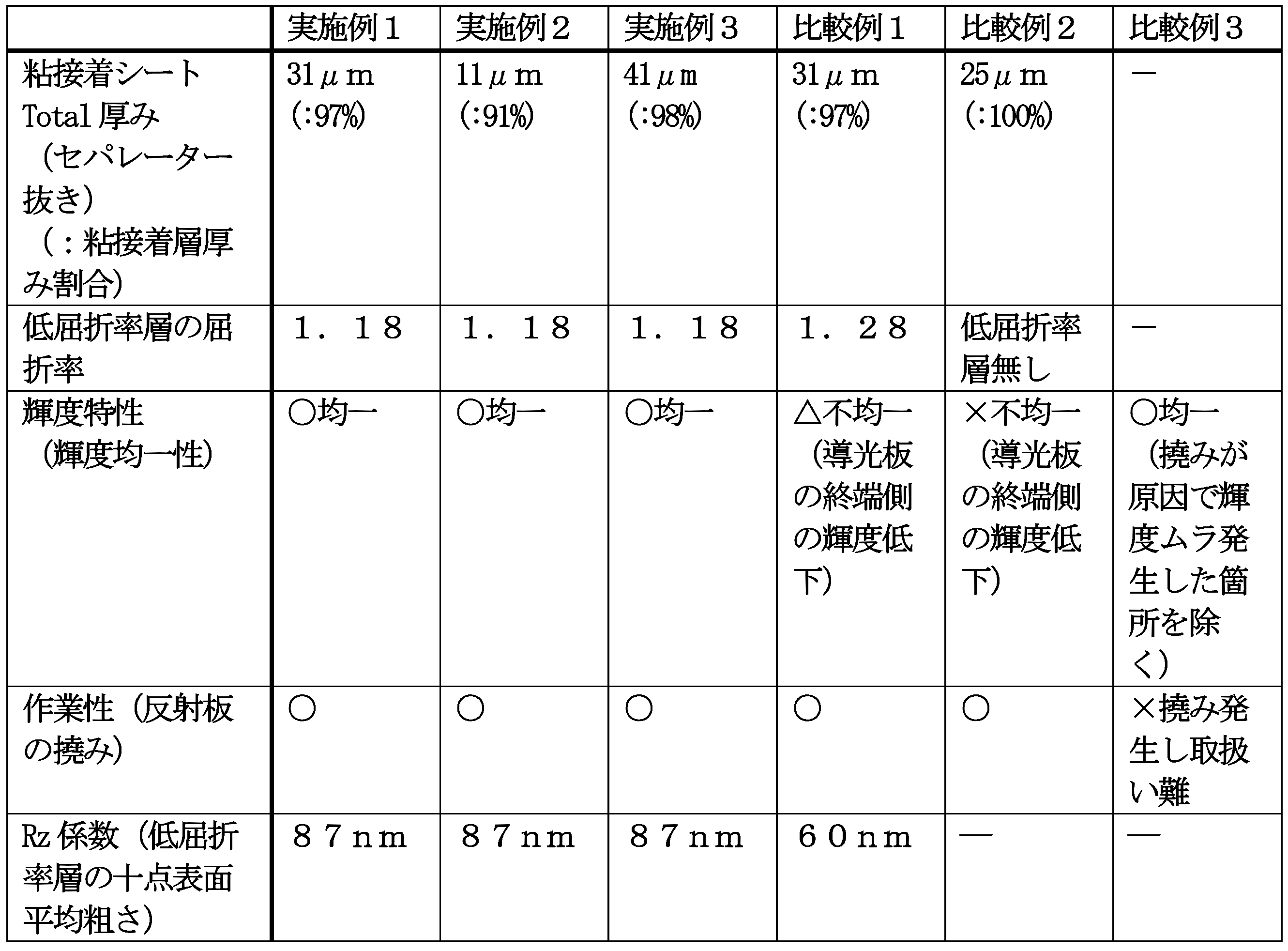
表1に示したとおり、実施例1および2の低屈折率層含有粘接着シートを用いて導光板と反射板を一体化させた場合、導光板の入射側から終端側までLEDからの光が伝播し、輝度特性が良好(輝度が均一)であった。また、導光板と反射板を一体化させた際における反射板の撓みもなく、作業性が良好であった。これに対し、低屈折率層の屈折率が1.25を超える比較例1、および低屈折率層が無い比較例2では、導光板と反射板を一体化させた場合に、導光板の終端側に光が伝播する前に光漏れが起きてしまい終端側にまで光が行き渡らなかったため、輝度が不均一であった。また、低屈折率層含有粘接着シートに代えて空気層を用いた比較例3では、導光板と反射板を一体化させた際における反射板の撓みが生じ、作業が困難であった。さらに、反射板の撓みに起因する輝度ムラも発生した。
As shown in Table 1, when the light guide plate and the reflector are integrated using the low refractive index layer-containing adhesive sheets of Examples 1 and 2, light from the LED from the incident side to the terminal side of the light guide plate Propagated and the luminance characteristics were good (brightness was uniform). Moreover, there was no bending of the reflecting plate when the light guide plate and the reflecting plate were integrated, and the workability was good. On the other hand, in Comparative Example 1 in which the refractive index of the low refractive index layer exceeds 1.25 and Comparative Example 2 without the low refractive index layer, when the light guide plate and the reflective plate are integrated, the end of the light guide plate Since the light leaked before the light propagated to the side and the light did not reach the terminal side, the luminance was non-uniform. In Comparative Example 3 using an air layer instead of the low refractive index layer-containing adhesive sheet, the reflector was bent when the light guide plate and the reflector were integrated, and the operation was difficult. Furthermore, luminance unevenness due to the deflection of the reflecting plate also occurred.
また、実施例1~3で用いた低屈折率層は、屈折率が1.18と極めて低い(すなわち空隙率が高い)にもかかわらず、表面粗さRz係数が87nmと小さかった。この87nmという数値は、比較例1の低屈折率層と比較しても、ほぼ遜色ない数値であった。このように表面粗さRz係数が小さい低屈折率層であると、前述のとおり、低屈折率層の表面の強度が落ちて傷つきやすくなる等の問題を抑制または防止しやすい。したがって、低屈折率層の表面の傷による光学特性の低下も抑制または防止しやすい。
In addition, the low refractive index layers used in Examples 1 to 3 had a surface roughness Rz coefficient as small as 87 nm, although the refractive index was extremely low as 1.18 (that is, the porosity was high). The numerical value of 87 nm is a numerical value that is almost comparable to the low refractive index layer of Comparative Example 1. As described above, the low refractive index layer having a small surface roughness Rz coefficient is easy to suppress or prevent problems such as the low strength of the surface of the low refractive index layer that is easily damaged. Therefore, it is easy to suppress or prevent a decrease in optical properties due to scratches on the surface of the low refractive index layer.
以上、説明したとおり、本発明によれば、薄型でかつ低屈折率な低屈折率層含有粘接着シート、低屈折率層含有粘接着シートの製造方法、および光学デバイスを提供することができる。本発明の用途は特に限定されず、例えば、液晶ディスプレイ、有機ELディスプレイ、マイクロLEDディスプレイ、有機EL照明等の光学デバイス全般に広く利用可能である。
As described above, according to the present invention, it is possible to provide a low refractive index layer-containing adhesive sheet that is thin and has a low refractive index, a method for producing a low refractive index layer-containing adhesive sheet, and an optical device. it can. The application of the present invention is not particularly limited, and can be widely used in general optical devices such as a liquid crystal display, an organic EL display, a micro LED display, and an organic EL illumination.
この出願は、2017年1月31日に出願された日本出願特願2017-016188、および、2017年10月4日に出願された日本出願特願2017-194713を基礎とする優先権を主張し、その開示の全てをここに取り込む。
This application claims priority based on Japanese Patent Application No. 2017-016188 filed on January 31, 2017 and Japanese Patent Application No. 2017-194713 filed on October 4, 2017. , The entire disclosure of which is incorporated herein.
10 基材
20 低屈折率層
20’ 塗工膜(前駆層)
20’’ ゲル粉砕物含有液
30 粘接着層(粘着剤)
40 セパレーター
101 送り出しローラ
102 塗工ロール
105 巻き取りロール
106 ロール
110 オーブンゾーン
111 熱風器(加熱手段)
120 化学処理ゾーン
121 ランプ(光照射手段)または熱風器(加熱手段)
201 送り出しローラ
202 液溜め
203 ドクター(ドクターナイフ)
204 マイクログラビア
210 オーブンゾーン
211 加熱手段
220 化学処理ゾーン
221 ランプ(光照射手段)または熱風器(加熱手段)
251 巻き取りロール 10Substrate 20 Low Refractive Index Layer 20 ′ Coating Film (Precursor Layer)
20 '' gel crushed product-containingliquid 30 Adhesive layer (adhesive)
40Separator 101 Delivery roller 102 Coating roll 105 Winding roll 106 Roll 110 Oven zone 111 Hot air (heating means)
120Chemical treatment zone 121 Lamp (light irradiation means) or hot air device (heating means)
201Feeding roller 202 Liquid reservoir 203 Doctor (doctor knife)
204Microgravure 210 Oven zone 211 Heating means 220 Chemical treatment zone 221 Lamp (light irradiation means) or hot air blower (heating means)
251 Winding roll
20 低屈折率層
20’ 塗工膜(前駆層)
20’’ ゲル粉砕物含有液
30 粘接着層(粘着剤)
40 セパレーター
101 送り出しローラ
102 塗工ロール
105 巻き取りロール
106 ロール
110 オーブンゾーン
111 熱風器(加熱手段)
120 化学処理ゾーン
121 ランプ(光照射手段)または熱風器(加熱手段)
201 送り出しローラ
202 液溜め
203 ドクター(ドクターナイフ)
204 マイクログラビア
210 オーブンゾーン
211 加熱手段
220 化学処理ゾーン
221 ランプ(光照射手段)または熱風器(加熱手段)
251 巻き取りロール 10
20 '' gel crushed product-containing
40
120
201
204
251 Winding roll
Claims (11)
- 第1の粘接着層、低屈折率層、および第2の粘接着層が、前記順序で積層され、
前記低屈折率層の屈折率が1.25以下であることを特徴とする低屈折率層含有粘接着シート。 The first adhesive layer, the low refractive index layer, and the second adhesive layer are laminated in the order,
The low refractive index layer-containing adhesive sheet, wherein the low refractive index layer has a refractive index of 1.25 or less. - 前記第1の粘接着層および前記第2の粘接着層の厚みの合計が、前記第1の粘接着層、前記低屈折率層、および前記第2の粘接着層の厚みの合計に対し85%以上である請求項1記載の低屈折率層含有粘接着シート。 The total thickness of the first adhesive layer and the second adhesive layer is equal to the thickness of the first adhesive layer, the low refractive index layer, and the second adhesive layer. The adhesive sheet containing a low refractive index layer according to claim 1, which is 85% or more based on the total.
- 前記低屈折率層が、空隙層である請求項1または2記載の低屈折率層含有粘接着シート。 The low refractive index layer-containing adhesive sheet according to claim 1 or 2, wherein the low refractive index layer is a void layer.
- 前記第1の粘接着層および前記第2の粘接着層の少なくとも一方において、前記低屈折率層と反対側の面にセパレーターが貼付されている請求項1から3のいずれか一項に記載の低屈折率層含有粘接着シート。 4. The separator according to claim 1, wherein a separator is attached to a surface opposite to the low refractive index layer in at least one of the first adhesive layer and the second adhesive layer. 5. The low refractive index layer containing adhesive sheet of description.
- 転写用樹脂フィルム基材上に前記低屈折率層を形成する低屈折率層形成工程と、
前記低屈折率層を前記粘接着層上に転写する転写工程と、
を含む、請求項1から4のいずれか一項に記載の低屈折率層含有粘接着シートの製造方法。 A low refractive index layer forming step of forming the low refractive index layer on the transfer resin film substrate;
A transfer step of transferring the low refractive index layer onto the adhesive layer;
The manufacturing method of the low-refractive-index layer containing adhesive sheet as described in any one of Claim 1 to 4 containing this. - 前記低屈折率層含有粘接着シートが、請求項4記載の低屈折率層含有粘接着シートであり、
さらに、前記粘接着層における前記低屈折率層と反対側の面に前記セパレーターを添付するセパレーター貼付工程を有する請求項5記載の製造方法。 The low refractive index layer-containing adhesive sheet is the low refractive index layer-containing adhesive sheet according to claim 4,
Furthermore, the manufacturing method of Claim 5 which has a separator sticking process which attaches the said separator to the surface on the opposite side to the said low-refractive-index layer in the said adhesive layer. - さらに、前記セパレーター貼付工程後に前記転写用樹脂フィルム基材を剥離する転写用樹脂フィルム基材剥離工程を有する請求項6記載の製造方法。 Furthermore, the manufacturing method of Claim 6 which has the transfer resin film base material peeling process which peels off the said transfer resin film base material after the said separator sticking process.
- 前記転写用樹脂フィルム基材と前記低屈折率層の剥離力よりも前記セパレーターと前記粘接着層の剥離力の方が大きい請求項7記載の製造方法。 The manufacturing method according to claim 7, wherein the peeling force between the separator and the adhesive layer is greater than the peeling force between the transfer resin film substrate and the low refractive index layer.
- 前記転写用樹脂フィルム基材が、脂環式構造含有樹脂により形成されている請求項5から8のいずれか一項に記載の製造方法。 The manufacturing method according to any one of claims 5 to 8, wherein the transfer resin film substrate is formed of an alicyclic structure-containing resin.
- 前記粘接着層上に前記低屈折率層の原料である塗工液を直接塗工する塗工工程と、
前記塗工液を乾燥する乾燥工程と、
を含む、請求項1から4のいずれか一項に記載の低屈折率層含有粘接着シートの製造方法。 A coating step of directly coating a coating liquid that is a raw material of the low refractive index layer on the adhesive layer;
A drying step of drying the coating solution;
The manufacturing method of the low-refractive-index layer containing adhesive sheet as described in any one of Claim 1 to 4 containing this. - 請求項1から4のいずれか一項に記載の低屈折率層含有粘接着シートと、第1の光学機能層と、第2の光学機能層と、を含み、
前記第1の光学機能層が、前記第1の粘接着層における前記低屈折率層と反対側の面に貼付され、
前記第2の光学機能層が、前記第2の粘接着層における前記低屈折率層と反対側の面に貼付されていることを特徴とする光学デバイス。 The low refractive index layer-containing adhesive sheet according to any one of claims 1 to 4, a first optical functional layer, and a second optical functional layer,
The first optical functional layer is affixed to the surface opposite to the low refractive index layer in the first adhesive layer,
The optical device, wherein the second optical functional layer is attached to a surface of the second adhesive layer opposite to the low refractive index layer.
Priority Applications (3)
| Application Number | Priority Date | Filing Date | Title |
|---|---|---|---|
| EP17895496.2A EP3575374A4 (en) | 2017-01-31 | 2017-12-25 | Low refractive index layer-containing adhesive sheet, method for producing low refractive index layer-containing adhesive sheet, and optical device |
| CN201780085241.2A CN110234720A (en) | 2017-01-31 | 2017-12-25 | The manufacturing method and optical device of adhesive/bonding sheet containing low-index layer, the adhesive/bonding sheet containing low-index layer |
| US16/482,105 US20200247089A1 (en) | 2017-01-31 | 2017-12-25 | Low refractive index layer-containing pressure-sensitive adhesive/adhesive sheet, method for producing the same, and optical device |
Applications Claiming Priority (4)
| Application Number | Priority Date | Filing Date | Title |
|---|---|---|---|
| JP2017-016188 | 2017-01-31 | ||
| JP2017016188 | 2017-01-31 | ||
| JP2017-194713 | 2017-10-04 | ||
| JP2017194713A JP7182358B2 (en) | 2017-01-31 | 2017-10-04 | Adhesive sheet containing low refractive index layer, method for producing adhesive sheet containing low refractive index layer, and optical device |
Publications (1)
| Publication Number | Publication Date |
|---|---|
| WO2018142813A1 true WO2018142813A1 (en) | 2018-08-09 |
Family
ID=63039492
Family Applications (1)
| Application Number | Title | Priority Date | Filing Date |
|---|---|---|---|
| PCT/JP2017/046457 WO2018142813A1 (en) | 2017-01-31 | 2017-12-25 | Low refractive index layer-containing adhesive sheet, method for producing low refractive index layer-containing adhesive sheet, and optical device |
Country Status (2)
| Country | Link |
|---|---|
| TW (1) | TWI756341B (en) |
| WO (1) | WO2018142813A1 (en) |
Cited By (7)
| Publication number | Priority date | Publication date | Assignee | Title |
|---|---|---|---|---|
| WO2019065999A1 (en) * | 2017-09-29 | 2019-04-04 | 日東電工株式会社 | Laminate, optical member and optical device |
| WO2020067345A1 (en) * | 2018-09-28 | 2020-04-02 | 日東電工株式会社 | Double-sided adhesive layer-equipped optical laminate |
| WO2020067344A1 (en) * | 2018-09-28 | 2020-04-02 | 日東電工株式会社 | Double-sided adhesive layer-equipped optical laminate |
| CN113168050A (en) * | 2018-12-06 | 2021-07-23 | 日东电工株式会社 | Optical laminate |
| EP3686006A4 (en) * | 2017-09-29 | 2021-08-25 | Nitto Denko Corporation | Laminate, optical member and optical device |
| WO2021193591A1 (en) | 2020-03-24 | 2021-09-30 | 日東電工株式会社 | Optical laminate with double-sided adhesive layer, and optical device |
| WO2024058165A1 (en) * | 2022-09-12 | 2024-03-21 | 株式会社日本触媒 | Silicon oxide gel dispersion, transparent low-refractive-index film, and method for manufacturing silicon oxide gel dispersion |
Citations (11)
| Publication number | Priority date | Publication date | Assignee | Title |
|---|---|---|---|---|
| JPH1062626A (en) | 1996-06-12 | 1998-03-06 | Nissha Printing Co Ltd | Surface light-emitting device and manufacture thereof |
| WO2004113966A1 (en) * | 2003-06-18 | 2004-12-29 | Asahi Kasei Kabushiki Kaisha | Antireflective film |
| JP2009063898A (en) * | 2007-09-07 | 2009-03-26 | Sumitomo Chemical Co Ltd | Light diffusing plate, surface light source device, and liquid crystal display unit |
| JP2012156082A (en) | 2011-01-28 | 2012-08-16 | Furukawa Electric Co Ltd:The | Backlight panel, light guide plate, reflection plate, and adhesive sheet |
| JP2014500519A (en) * | 2010-10-20 | 2014-01-09 | スリーエム イノベイティブ プロパティズ カンパニー | Low refractive index diffuser element with interconnected voids |
| WO2014024873A1 (en) * | 2012-08-06 | 2014-02-13 | コニカミノルタ株式会社 | Light-reflective film, and light reflector produced using same |
| JP2015200865A (en) * | 2014-03-31 | 2015-11-12 | 日東電工株式会社 | Optical member, polarizing plate set and liquid crystal display apparatus |
| JP2015200866A (en) * | 2014-03-31 | 2015-11-12 | 日東電工株式会社 | Optical member, polarizing plate set and liquid crystal display apparatus |
| JP2016104551A (en) * | 2014-11-21 | 2016-06-09 | 三菱化学株式会社 | Porous laminate |
| JP2017016188A (en) | 2015-06-26 | 2017-01-19 | 東芝メディカルシステムズ株式会社 | Medical document creation system and medical document creation program |
| JP2017194713A (en) | 2012-06-14 | 2017-10-26 | 三井化学株式会社 | Electronic lens and electronic eye wear |
-
2017
- 2017-12-25 WO PCT/JP2017/046457 patent/WO2018142813A1/en unknown
-
2018
- 2018-01-19 TW TW107102019A patent/TWI756341B/en active
Patent Citations (11)
| Publication number | Priority date | Publication date | Assignee | Title |
|---|---|---|---|---|
| JPH1062626A (en) | 1996-06-12 | 1998-03-06 | Nissha Printing Co Ltd | Surface light-emitting device and manufacture thereof |
| WO2004113966A1 (en) * | 2003-06-18 | 2004-12-29 | Asahi Kasei Kabushiki Kaisha | Antireflective film |
| JP2009063898A (en) * | 2007-09-07 | 2009-03-26 | Sumitomo Chemical Co Ltd | Light diffusing plate, surface light source device, and liquid crystal display unit |
| JP2014500519A (en) * | 2010-10-20 | 2014-01-09 | スリーエム イノベイティブ プロパティズ カンパニー | Low refractive index diffuser element with interconnected voids |
| JP2012156082A (en) | 2011-01-28 | 2012-08-16 | Furukawa Electric Co Ltd:The | Backlight panel, light guide plate, reflection plate, and adhesive sheet |
| JP2017194713A (en) | 2012-06-14 | 2017-10-26 | 三井化学株式会社 | Electronic lens and electronic eye wear |
| WO2014024873A1 (en) * | 2012-08-06 | 2014-02-13 | コニカミノルタ株式会社 | Light-reflective film, and light reflector produced using same |
| JP2015200865A (en) * | 2014-03-31 | 2015-11-12 | 日東電工株式会社 | Optical member, polarizing plate set and liquid crystal display apparatus |
| JP2015200866A (en) * | 2014-03-31 | 2015-11-12 | 日東電工株式会社 | Optical member, polarizing plate set and liquid crystal display apparatus |
| JP2016104551A (en) * | 2014-11-21 | 2016-06-09 | 三菱化学株式会社 | Porous laminate |
| JP2017016188A (en) | 2015-06-26 | 2017-01-19 | 東芝メディカルシステムズ株式会社 | Medical document creation system and medical document creation program |
Cited By (20)
| Publication number | Priority date | Publication date | Assignee | Title |
|---|---|---|---|---|
| EP3686006A4 (en) * | 2017-09-29 | 2021-08-25 | Nitto Denko Corporation | Laminate, optical member and optical device |
| WO2019065999A1 (en) * | 2017-09-29 | 2019-04-04 | 日東電工株式会社 | Laminate, optical member and optical device |
| US11420413B2 (en) | 2017-09-29 | 2022-08-23 | Nitto Denko Corporation | Laminate, optical member, and optical apparatus |
| CN112771414B (en) * | 2018-09-28 | 2023-04-28 | 日东电工株式会社 | Optical laminate with adhesive layer on both sides |
| EP3859408A4 (en) * | 2018-09-28 | 2022-07-13 | Nitto Denko Corporation | Double-sided adhesive layer-equipped optical laminate |
| US11891549B2 (en) | 2018-09-28 | 2024-02-06 | Nitto Denko Corporation | Double-sided adhesive layer-equipped optical laminate |
| CN112771413A (en) * | 2018-09-28 | 2021-05-07 | 日东电工株式会社 | Optical laminate with adhesive layers on both sides |
| JPWO2020067345A1 (en) * | 2018-09-28 | 2021-09-16 | 日東電工株式会社 | Optical laminate with double-sided adhesive layer |
| JPWO2020067344A1 (en) * | 2018-09-28 | 2021-09-24 | 日東電工株式会社 | Optical laminate with double-sided adhesive layer |
| WO2020067345A1 (en) * | 2018-09-28 | 2020-04-02 | 日東電工株式会社 | Double-sided adhesive layer-equipped optical laminate |
| JP7054740B2 (en) | 2018-09-28 | 2022-04-14 | 日東電工株式会社 | Optical laminate with double-sided adhesive layer |
| EP3859407A4 (en) * | 2018-09-28 | 2022-07-13 | Nitto Denko Corporation | Double-sided adhesive layer-equipped optical laminate |
| CN112771414A (en) * | 2018-09-28 | 2021-05-07 | 日东电工株式会社 | Optical laminate with adhesive layers on both sides |
| WO2020067344A1 (en) * | 2018-09-28 | 2020-04-02 | 日東電工株式会社 | Double-sided adhesive layer-equipped optical laminate |
| JP7249356B2 (en) | 2018-09-28 | 2023-03-30 | 日東電工株式会社 | Optical laminate with double-sided adhesive layer |
| CN113168050A (en) * | 2018-12-06 | 2021-07-23 | 日东电工株式会社 | Optical laminate |
| WO2021193591A1 (en) | 2020-03-24 | 2021-09-30 | 日東電工株式会社 | Optical laminate with double-sided adhesive layer, and optical device |
| JP7345634B2 (en) | 2020-03-24 | 2023-09-15 | 日東電工株式会社 | Optical laminate with double-sided adhesive layer and optical device |
| EP4130809A4 (en) * | 2020-03-24 | 2024-04-17 | Nitto Denko Corp | Optical laminate with double-sided adhesive layer, and optical device |
| WO2024058165A1 (en) * | 2022-09-12 | 2024-03-21 | 株式会社日本触媒 | Silicon oxide gel dispersion, transparent low-refractive-index film, and method for manufacturing silicon oxide gel dispersion |
Also Published As
| Publication number | Publication date |
|---|---|
| TWI756341B (en) | 2022-03-01 |
| TW201832919A (en) | 2018-09-16 |
Similar Documents
| Publication | Publication Date | Title |
|---|---|---|
| JP7182358B2 (en) | Adhesive sheet containing low refractive index layer, method for producing adhesive sheet containing low refractive index layer, and optical device | |
| WO2018142813A1 (en) | Low refractive index layer-containing adhesive sheet, method for producing low refractive index layer-containing adhesive sheet, and optical device | |
| JP6606518B2 (en) | Optical sheet for light guide plate type liquid crystal display, backlight unit for light guide plate type liquid crystal display, and light guide plate type liquid crystal display | |
| JP6580101B2 (en) | Void layer, laminate, method for producing gap layer, optical member and optical device | |
| JP6604781B2 (en) | Laminated film roll and method for producing the same | |
| JP2018123233A (en) | Void layer, void layer-containing adhesive sheet, method for producing void layer, method for producing void layer-containing adhesive sheet, and optical device | |
| JP6563750B2 (en) | Paint and production method thereof | |
| WO2018008534A1 (en) | Optical laminate manufacturing method and optical laminate intermediate body | |
| WO2017022690A1 (en) | Optical laminate, optical laminate manufacturing method, optical member, and image display device | |
| WO2016104764A1 (en) | Laminated film roll and method for producing same | |
| WO2017043496A1 (en) | Low-refractive-index layer, laminated film, method for producing low-refractive-index layer, method for producing laminated film, optical member, and image display device | |
| TW202200726A (en) | Optical laminate with double-sided adhesive layer, and optical device | |
| CN112771413B (en) | Optical laminate with adhesive layer on both sides | |
| JP2017064954A (en) | Method for producing laminated film and method for producing image display device | |
| CN112771414B (en) | Optical laminate with adhesive layer on both sides | |
| WO2016104765A1 (en) | Coating material and method for manufacturing same | |
| JP6609721B1 (en) | Void layer, laminate, method for producing gap layer, optical member and optical device | |
| JP2018125153A (en) | Optical sheet for direct-type liquid crystal display, backlight unit for direct-type liquid crystal display, and direct-type liquid crystal display | |
| TWI783986B (en) | Optical sheet for light guide plate type liquid crystal display, backlight unit for light guide plate type liquid crystal display, and light guide plate type liquid crystal display | |
| WO2017131220A1 (en) | Method for producing liquid that contains pulverized gel | |
| JP2017066209A (en) | Coating liquid, method for producing coating liquid, method for producing laminated film and method for producing image display device | |
| WO2017131219A1 (en) | Pulverized-gel-containing liquid, and method for producing pulverized-gel-containing liquid | |
| TW202023806A (en) | Optical laminate | |
| WO2016104763A1 (en) | Void structured film bonded through catalytic action and method for manufacturing same | |
| JP2017132675A (en) | Gel, production method of gel, and production method of pulverized gel product-containing liquid |
Legal Events
| Date | Code | Title | Description |
|---|---|---|---|
| 121 | Ep: the epo has been informed by wipo that ep was designated in this application |
Ref document number: 17895496 Country of ref document: EP Kind code of ref document: A1 |
|
| NENP | Non-entry into the national phase |
Ref country code: DE |
|
| ENP | Entry into the national phase |
Ref document number: 2017895496 Country of ref document: EP Effective date: 20190828 |