WO2018139500A1 - スクロール型圧縮機 - Google Patents
スクロール型圧縮機 Download PDFInfo
- Publication number
- WO2018139500A1 WO2018139500A1 PCT/JP2018/002175 JP2018002175W WO2018139500A1 WO 2018139500 A1 WO2018139500 A1 WO 2018139500A1 JP 2018002175 W JP2018002175 W JP 2018002175W WO 2018139500 A1 WO2018139500 A1 WO 2018139500A1
- Authority
- WO
- WIPO (PCT)
- Prior art keywords
- scroll
- bearing
- drive
- seal
- housing
- Prior art date
Links
Images

Classifications
-
- F—MECHANICAL ENGINEERING; LIGHTING; HEATING; WEAPONS; BLASTING
- F04—POSITIVE - DISPLACEMENT MACHINES FOR LIQUIDS; PUMPS FOR LIQUIDS OR ELASTIC FLUIDS
- F04C—ROTARY-PISTON, OR OSCILLATING-PISTON, POSITIVE-DISPLACEMENT MACHINES FOR LIQUIDS; ROTARY-PISTON, OR OSCILLATING-PISTON, POSITIVE-DISPLACEMENT PUMPS
- F04C27/00—Sealing arrangements in rotary-piston pumps specially adapted for elastic fluids
- F04C27/008—Sealing arrangements in rotary-piston pumps specially adapted for elastic fluids for other than working fluid, i.e. the sealing arrangements are not between working chambers of the machine
-
- F—MECHANICAL ENGINEERING; LIGHTING; HEATING; WEAPONS; BLASTING
- F04—POSITIVE - DISPLACEMENT MACHINES FOR LIQUIDS; PUMPS FOR LIQUIDS OR ELASTIC FLUIDS
- F04C—ROTARY-PISTON, OR OSCILLATING-PISTON, POSITIVE-DISPLACEMENT MACHINES FOR LIQUIDS; ROTARY-PISTON, OR OSCILLATING-PISTON, POSITIVE-DISPLACEMENT PUMPS
- F04C18/00—Rotary-piston pumps specially adapted for elastic fluids
- F04C18/02—Rotary-piston pumps specially adapted for elastic fluids of arcuate-engagement type, i.e. with circular translatory movement of co-operating members, each member having the same number of teeth or tooth-equivalents
- F04C18/0207—Rotary-piston pumps specially adapted for elastic fluids of arcuate-engagement type, i.e. with circular translatory movement of co-operating members, each member having the same number of teeth or tooth-equivalents both members having co-operating elements in spiral form
- F04C18/023—Rotary-piston pumps specially adapted for elastic fluids of arcuate-engagement type, i.e. with circular translatory movement of co-operating members, each member having the same number of teeth or tooth-equivalents both members having co-operating elements in spiral form where both members are moving
- F04C18/0238—Rotary-piston pumps specially adapted for elastic fluids of arcuate-engagement type, i.e. with circular translatory movement of co-operating members, each member having the same number of teeth or tooth-equivalents both members having co-operating elements in spiral form where both members are moving with symmetrical double wraps
-
- F—MECHANICAL ENGINEERING; LIGHTING; HEATING; WEAPONS; BLASTING
- F04—POSITIVE - DISPLACEMENT MACHINES FOR LIQUIDS; PUMPS FOR LIQUIDS OR ELASTIC FLUIDS
- F04C—ROTARY-PISTON, OR OSCILLATING-PISTON, POSITIVE-DISPLACEMENT MACHINES FOR LIQUIDS; ROTARY-PISTON, OR OSCILLATING-PISTON, POSITIVE-DISPLACEMENT PUMPS
- F04C18/00—Rotary-piston pumps specially adapted for elastic fluids
- F04C18/02—Rotary-piston pumps specially adapted for elastic fluids of arcuate-engagement type, i.e. with circular translatory movement of co-operating members, each member having the same number of teeth or tooth-equivalents
- F04C18/0207—Rotary-piston pumps specially adapted for elastic fluids of arcuate-engagement type, i.e. with circular translatory movement of co-operating members, each member having the same number of teeth or tooth-equivalents both members having co-operating elements in spiral form
- F04C18/023—Rotary-piston pumps specially adapted for elastic fluids of arcuate-engagement type, i.e. with circular translatory movement of co-operating members, each member having the same number of teeth or tooth-equivalents both members having co-operating elements in spiral form where both members are moving
-
- F—MECHANICAL ENGINEERING; LIGHTING; HEATING; WEAPONS; BLASTING
- F04—POSITIVE - DISPLACEMENT MACHINES FOR LIQUIDS; PUMPS FOR LIQUIDS OR ELASTIC FLUIDS
- F04C—ROTARY-PISTON, OR OSCILLATING-PISTON, POSITIVE-DISPLACEMENT MACHINES FOR LIQUIDS; ROTARY-PISTON, OR OSCILLATING-PISTON, POSITIVE-DISPLACEMENT PUMPS
- F04C2/00—Rotary-piston machines or pumps
- F04C2/02—Rotary-piston machines or pumps of arcuate-engagement type, i.e. with circular translatory movement of co-operating members, each member having the same number of teeth or tooth-equivalents
- F04C2/04—Rotary-piston machines or pumps of arcuate-engagement type, i.e. with circular translatory movement of co-operating members, each member having the same number of teeth or tooth-equivalents of internal axis type
- F04C2/045—Rotary-piston machines or pumps of arcuate-engagement type, i.e. with circular translatory movement of co-operating members, each member having the same number of teeth or tooth-equivalents of internal axis type having a C-shaped piston
-
- F—MECHANICAL ENGINEERING; LIGHTING; HEATING; WEAPONS; BLASTING
- F04—POSITIVE - DISPLACEMENT MACHINES FOR LIQUIDS; PUMPS FOR LIQUIDS OR ELASTIC FLUIDS
- F04C—ROTARY-PISTON, OR OSCILLATING-PISTON, POSITIVE-DISPLACEMENT MACHINES FOR LIQUIDS; ROTARY-PISTON, OR OSCILLATING-PISTON, POSITIVE-DISPLACEMENT PUMPS
- F04C27/00—Sealing arrangements in rotary-piston pumps specially adapted for elastic fluids
- F04C27/008—Sealing arrangements in rotary-piston pumps specially adapted for elastic fluids for other than working fluid, i.e. the sealing arrangements are not between working chambers of the machine
- F04C27/009—Shaft sealings specially adapted for pumps
-
- F—MECHANICAL ENGINEERING; LIGHTING; HEATING; WEAPONS; BLASTING
- F04—POSITIVE - DISPLACEMENT MACHINES FOR LIQUIDS; PUMPS FOR LIQUIDS OR ELASTIC FLUIDS
- F04C—ROTARY-PISTON, OR OSCILLATING-PISTON, POSITIVE-DISPLACEMENT MACHINES FOR LIQUIDS; ROTARY-PISTON, OR OSCILLATING-PISTON, POSITIVE-DISPLACEMENT PUMPS
- F04C29/00—Component parts, details or accessories of pumps or pumping installations, not provided for in groups F04C18/00 - F04C28/00
- F04C29/02—Lubrication; Lubricant separation
-
- F—MECHANICAL ENGINEERING; LIGHTING; HEATING; WEAPONS; BLASTING
- F04—POSITIVE - DISPLACEMENT MACHINES FOR LIQUIDS; PUMPS FOR LIQUIDS OR ELASTIC FLUIDS
- F04C—ROTARY-PISTON, OR OSCILLATING-PISTON, POSITIVE-DISPLACEMENT MACHINES FOR LIQUIDS; ROTARY-PISTON, OR OSCILLATING-PISTON, POSITIVE-DISPLACEMENT PUMPS
- F04C29/00—Component parts, details or accessories of pumps or pumping installations, not provided for in groups F04C18/00 - F04C28/00
- F04C29/04—Heating; Cooling; Heat insulation
- F04C29/042—Heating; Cooling; Heat insulation by injecting a fluid
-
- F—MECHANICAL ENGINEERING; LIGHTING; HEATING; WEAPONS; BLASTING
- F04—POSITIVE - DISPLACEMENT MACHINES FOR LIQUIDS; PUMPS FOR LIQUIDS OR ELASTIC FLUIDS
- F04C—ROTARY-PISTON, OR OSCILLATING-PISTON, POSITIVE-DISPLACEMENT MACHINES FOR LIQUIDS; ROTARY-PISTON, OR OSCILLATING-PISTON, POSITIVE-DISPLACEMENT PUMPS
- F04C29/00—Component parts, details or accessories of pumps or pumping installations, not provided for in groups F04C18/00 - F04C28/00
- F04C29/12—Arrangements for admission or discharge of the working fluid, e.g. constructional features of the inlet or outlet
-
- F—MECHANICAL ENGINEERING; LIGHTING; HEATING; WEAPONS; BLASTING
- F16—ENGINEERING ELEMENTS AND UNITS; GENERAL MEASURES FOR PRODUCING AND MAINTAINING EFFECTIVE FUNCTIONING OF MACHINES OR INSTALLATIONS; THERMAL INSULATION IN GENERAL
- F16J—PISTONS; CYLINDERS; SEALINGS
- F16J15/00—Sealings
- F16J15/16—Sealings between relatively-moving surfaces
- F16J15/32—Sealings between relatively-moving surfaces with elastic sealings, e.g. O-rings
- F16J15/3204—Sealings between relatively-moving surfaces with elastic sealings, e.g. O-rings with at least one lip
-
- F—MECHANICAL ENGINEERING; LIGHTING; HEATING; WEAPONS; BLASTING
- F04—POSITIVE - DISPLACEMENT MACHINES FOR LIQUIDS; PUMPS FOR LIQUIDS OR ELASTIC FLUIDS
- F04C—ROTARY-PISTON, OR OSCILLATING-PISTON, POSITIVE-DISPLACEMENT MACHINES FOR LIQUIDS; ROTARY-PISTON, OR OSCILLATING-PISTON, POSITIVE-DISPLACEMENT PUMPS
- F04C15/00—Component parts, details or accessories of machines, pumps or pumping installations, not provided for in groups F04C2/00 - F04C14/00
- F04C15/0088—Lubrication
-
- F—MECHANICAL ENGINEERING; LIGHTING; HEATING; WEAPONS; BLASTING
- F04—POSITIVE - DISPLACEMENT MACHINES FOR LIQUIDS; PUMPS FOR LIQUIDS OR ELASTIC FLUIDS
- F04C—ROTARY-PISTON, OR OSCILLATING-PISTON, POSITIVE-DISPLACEMENT MACHINES FOR LIQUIDS; ROTARY-PISTON, OR OSCILLATING-PISTON, POSITIVE-DISPLACEMENT PUMPS
- F04C2240/00—Components
- F04C2240/50—Bearings
- F04C2240/56—Bearing bushings or details thereof
Definitions
- the present invention relates to a scroll compressor suitable for use in, for example, a double-rotation scroll compressor.
- a double-rotating scroll compressor is known (see Patent Document 1).
- a seal plate that seals the high-pressure side occupied by the compressed working fluid and the low-pressure side, which is the internal space of the housing, is provided on the front end surface of the discharge cylinder.
- Patent Document 1 sealing is performed in a state where a seal plate 48 sandwiched between the distal end surface of the discharge cylinder 46 and the boss portion 50 is pressed in the axial direction (the reference is described in Patent Document 1). Sign). However, when the force for pressing the seal plate in the axial direction is not sufficient, the sealing performance may be deteriorated.
- the present invention has been made in view of such circumstances, and is a scroll capable of reducing the axial dimension of the discharge cylinder while enabling the supply of lubricant when sealing the outer peripheral surface of the discharge cylinder rotating around the axis.
- An object is to provide a mold compressor.
- a scroll compressor includes a pair of scroll members having a compression chamber that compresses the working fluid, a housing that houses the pair of scroll members, and the compressed working fluid.
- a discharge cylinder that discharges from the compression chamber and rotates about the axis with respect to the housing; a bearing that rotatably supports the discharge cylinder with respect to the housing; and an outlet side of the discharge cylinder from the bearing.
- a seal member that seals the outer peripheral surface of the discharge cylinder, and a lubricant is sealed in a space formed between the bearing and the seal member.
- the space for sealing the lubricant can be configured without waste.
- two seal members are arranged side by side in the axial direction, and only one seal member is required as compared with a configuration in which a lubricant is sealed between them, the number of parts can be reduced, and the axial dimension of the discharge cylinder can be reduced. it can. Therefore, the outer peripheral surface of the discharge cylinder can be compactly sealed, and the pressure loss of the working fluid can be reduced.
- the seal member is lubricated by the lubricant enclosed between the seal member and the bearing, and wear can be reduced. Even if an oil-less compressor is used when a clean working fluid that does not contain oil is desired at the place where the compressed working fluid is demanded, the scroll type compressor of the present invention can reduce wear of the seal member. Can do.
- the bearing is a rolling bearing having seal plates on both side surfaces, and the seal plate is fixed to an outer ring of the bearing, and the bearing The inner ring may be non-contact.
- a rolling bearing with a seal plate on the end face side When a rolling bearing with a seal plate on the end face side is used as a bearing, it is a non-contact type in which the seal plate and the inner ring do not contact each other, preventing energy loss due to heat generation due to contact, and scroll type. A decrease in the system efficiency of the compressor can be prevented.
- the bearing is a rolling bearing provided with a seal plate on a side surface opposite to the seal member side, and a seal plate is provided on the side surface on the seal member side. It is good also as a structure which is not provided.
- the seal plate on the seal member side can be omitted.
- a seal plate is installed to prevent leakage of the lubricant.
- the seal member may be an oil seal.
- the scroll compressor includes a drive shaft that is rotationally driven by a drive unit, and the pair of scroll members are coupled to the drive shaft and perform a rotational motion; Further, it may be a double-rotating scroll type compressor having a driven-side scroll member that performs a rotational motion when power is transmitted from the driving-side scroll member.
- a double-rotating scroll compressor without a stationary scroll member has a significant risk of wear of the seal member, and wear can be reduced by arranging a lubricant between the seal member and the bearing.
- the axial dimension of the discharge cylinder can be reduced while allowing the lubricant to be supplied when sealing the outer peripheral surface of the discharge cylinder rotating around the axis.
- FIG. 1 shows a double-rotating scroll compressor (scroll compressor) 1.
- the double-rotating scroll compressor 1 can be used as a supercharger that compresses combustion air (fluid) supplied to an internal combustion engine such as a vehicle engine.
- the double-rotating scroll compressor 1 includes a housing 3, a motor (drive unit) 5 housed on one end side of the housing 3, a drive-side scroll member 70 and a driven-side scroll member housed on the other end side of the housing 3. 90.
- the housing 3 has a substantially cylindrical shape, and includes a motor accommodating portion (first housing) 3 a that accommodates the motor 5, and a scroll accommodating portion (second housing) 3 b that accommodates the scroll members 70 and 90. .
- Cooling fins 3c for cooling the motor 5 are provided on the outer periphery of the motor housing 3a.
- a discharge port 3d for discharging compressed air (working fluid) is formed at the end of the scroll accommodating portion 3b.
- the housing 3 is provided with an air suction port for sucking air (working fluid).
- the scroll accommodating portion 3 b of the housing 3 is divided by a dividing surface P located at a substantially central portion in the axial direction of the scroll members 70 and 90.
- the housing 3 is provided with a flange portion (not shown) protruding outward at a predetermined position in the circumferential direction.
- the split surface P is fastened by fixing to the flange portion through a bolt or the like as a fastening means.
- the motor 5 is driven by power supplied from a power supply source (not shown).
- the rotation control of the motor 5 is performed by a command from a control unit (not shown).
- the stator 5 a of the motor 5 is fixed to the inner peripheral side of the housing 3.
- the rotor 5b of the motor 5 rotates around the drive side rotation axis CL1.
- a drive shaft 6 extending on the drive side rotation axis CL1 is connected to the rotor 5b.
- the drive shaft 6 is connected to the first drive side shaft portion 7 c of the drive side scroll member 70.
- the drive-side scroll member 70 includes a first drive-side scroll portion 71 on the motor 5 side and a second drive-side scroll portion 72 on the discharge port 3d side.
- the first drive side scroll portion 71 includes a first drive side end plate 71a and a first drive side wall 71b.
- the first drive side end plate 71a is connected to a first drive side shaft portion 7c connected to the drive shaft 6, and extends in a direction orthogonal to the drive side rotation axis CL1.
- the first drive side shaft portion 7c is provided to be rotatable with respect to the housing 3 via a first drive side bearing 11 which is a ball bearing.
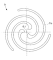
- the first drive side end plate 71a has a substantially disc shape when viewed in plan. On the first drive side end plate 71a, a spiral first drive side wall 71b is provided. Three first drive side walls 71b are arranged at equal intervals around the drive side rotation axis CL1 (see FIG. 5).
- the second drive side scroll part 72 includes a second drive side end plate 72a and a second drive side wall 72b.
- the second drive side wall 72b has a spiral shape, similar to the first drive side wall 71b described above.
- a cylindrical second drive side shaft portion (discharge cylinder) 72c extending in the direction of the drive side rotation axis CL1 is connected to the second drive side end plate 72a.
- the second drive side shaft portion 72c is rotatably provided with respect to the housing 3 via the second drive side bearing 14 which is a ball bearing.
- a discharge port 72d is formed in the second drive side end plate 72a along the drive side rotation axis CL1.
- a seal member 16 is provided between the second drive side shaft portion 72c and the housing 3, on the downstream side in the discharge direction of the compressed air from the second drive side bearing 14, that is, on the distal end side serving as the free end of the second drive side shaft portion 72c.
- the seal member 16 and the second drive side bearing 14 are arranged with a predetermined interval in the direction of the drive side rotation axis CL1, and a space R is formed between them.
- the first drive side scroll part 71 and the second drive side scroll part 72 are fixed in a state where the tips (free ends) of the wall bodies 71b and 72b face each other.
- the first drive-side scroll portion 71 and the second drive-side scroll portion 72 are fixed by bolts (wall body fixing) fastened to flange portions 73 provided at a plurality of locations in the circumferential direction so as to protrude outward in the radial direction. Part) 31.
- the driven scroll member 90 includes a first driven scroll part 91 and a second driven scroll part 92.
- the driven side end plates 91a and 92a are located at substantially the center in the axial direction (horizontal direction in the drawing) of the driven side scroll member 90.
- Both driven side end plates 91a and 92a are fixed in a state in which the respective back surfaces (other side surfaces) are overlapped and in contact with each other.
- this fixing is performed by a bolt, a pin, or the like.
- a through hole 90h is formed in the center of each driven side end plate 91a, 92a so that the compressed air flows to the discharge port 72d.
- a first driven side wall body 91b is provided on one side surface of the first driven side end plate 91a, and a second driven side wall body 92b is provided on one side surface of the second driven side end plate 92a.
- the first driven side wall body 91b installed on the motor 5 side from the first driven side end plate 91a is meshed with the first driving side wall body 71b of the first driving side scroll portion 71 and discharged from the second driven side end plate 92a.
- the second driven side wall 92b installed on the outlet 3d side is engaged with the second driving side wall 72b of the second driving side scroll portion 72.
- Support members 33 and 35 which will be described later, are fixed on the outer periphery of the first driven side wall 91b.
- the second driven side wall 92b has the same configuration.
- a first support member 33 and a second support member 35 are provided at both ends in the axial direction (horizontal direction in the drawing) of the driven scroll member 90.
- the first support member 33 is disposed on the motor 5 side, and the second support member 35 is disposed on the discharge port 3d side.
- the first support member 33 is fixed to the tip (free end) of the first driven side wall 91b, and the second support member 35 is fixed to the tip (free end) of the second driven side wall 92b.
- a shaft portion 33 a is provided on the center shaft side of the first support member 33, and the shaft portion 33 a is fixed to the housing 3 via a first support member bearing 37.
- a shaft portion 35 a is provided on the center shaft side of the second support member 35, and the shaft portion 35 a is fixed to the housing 3 via a second support member bearing 38.
- the driven scroll member 90 rotates around the driven rotation axis CL2 via the support members 33 and 35.
- a pin ring mechanism (synchronous drive mechanism) 15 is provided between the first support member 33 and the first drive side end plate 71a. That is, the first drive side end plate 71 a is provided with a circular hole, and the first support member 33 is provided with the pin member 15 b. A driving force is transmitted from the driving side scroll member 70 to the driven side scroll member 90 by the pin ring mechanism 15, and both scroll members 70, 90 are rotated in the same direction at the same angular velocity.
- the scroll accommodating portion 3b includes a second drive side shaft portion accommodating portion 3b1 that accommodates the second drive side shaft portion 72c, and the outer peripheral surface X of the second drive side shaft portion 72c. And a second drive-side bearing 14 is provided between the second drive-side shaft portion accommodating portion 3b1 and the inner peripheral surface Y.
- the seal member 16 is an oil seal, and as shown in FIG. 2, the position in the axial direction is regulated by a stopper ring 19 fitted into the inner peripheral surface Y of the second drive side shaft accommodating portion 3b1. Yes.
- the seal member 16 includes a resin seal lip portion 16a.
- the seal lip portion 16a includes a lip tip portion 16a1 that protrudes toward the inner peripheral side and contacts the outer peripheral surface X of the second drive side shaft portion 72c.
- An annular spring 16a2 is provided on the back side (outer peripheral side) of the seal lip portion 16a. The lip tip portion 16a1 is pressed over the entire circumference of the outer peripheral surface X of the second drive side shaft portion 72c by the elastic force of the spring 16a2.
- the double-rotating scroll compressor 1 having the above-described configuration operates as follows.
- the drive shaft 6 is rotated around the drive-side rotation axis CL1 by the motor 5
- the first drive-side shaft portion 7c connected to the drive shaft 6 also rotates, thereby causing the drive-side scroll member 70 to move to the drive-side rotation axis CL1.
- the driving scroll member 70 rotates, the driving force is transmitted from the support members 33 and 35 to the driven scroll member 90 via the pin ring mechanism 15, and the driven scroll member 90 rotates about the driven rotation axis CL2. To do.
- both scroll members 70 and 90 rotate in the same direction at the same angular velocity.
- the air sucked from the suction port of the housing 3 is sucked from the outer peripheral sides of the scroll members 70 and 90 and is formed by the scroll members 70 and 90.
- the compression chamber formed by the first drive side wall 71b and the first driven side wall 91b and the compression chamber formed by the second drive side wall 72b and the second driven side wall 92b are separately compressed. The Each compression chamber decreases in volume as it moves toward the center, and air is compressed accordingly.
- the air compressed by the first drive side wall 71b and the first driven side wall 91b passes through the through holes 90h formed in the driven side end plates 91a and 92a, and the second drive side wall 72b and the second driven side wall.
- the air compressed by 92b merges, and the merged air passes through the discharge port 72d and is discharged from the discharge port 3d of the housing 3 to the outside.
- the discharged compressed air is guided to an internal combustion engine (not shown) and used as combustion air.
- the compressed air before being discharged from the discharge port 3d to the outside is occupied by the high-pressure space HP and the suction port of the housing 3, and is sucked from the outer peripheral sides of the scroll members 70 and 90.
- the low pressure space LP occupied by the intake air is partitioned by the seal member 16, the lubricant 17, and the second drive side bearing 14.
- the lip tip portion 16a1 which is the tip of the seal lip portion 16a of the seal member 16, is pressed against the outer peripheral surface X of the second drive side shaft portion 72c by the spring 16a2 provided on the seal lip portion 16a, and the lip tip portion 16a1 and the first lip tip portion 16a1.
- An oil film is formed by the lubricant 17 between the outer peripheral surface X of the two drive side shaft portion 72c.
- the space R is formed between the seal member 16 and the second drive side bearing 14 that rotatably supports the second drive side shaft portion 72c, and the lubricant 17 is enclosed in the space R, the lubricant
- the space for enclosing 17 can be configured without waste.
- the number of parts can be reduced and the axial dimension of the second drive side shaft portion 72c can be reduced as compared with the configuration in which two seal members are arranged side by side in the axial direction and the lubricant is sealed therebetween. Therefore, the outer peripheral surface X of the second drive side shaft portion 72c can be compactly sealed, and the pressure loss of the compressed air can be reduced.
- the sealing member 16 is lubricated by the lubricant 17 enclosed between the sealing member 16 and the second drive side bearing 14, and thus wear. Can be reduced. Even if an oil-less compressor is used when clean compressed air that does not contain oil is desired at a demand destination of compressed air, the scroll compressor 1 of the present embodiment can reduce wear of the seal member. it can.
- the second drive side bearing 14 may be a seal-type ball bearing.
- the second drive side bearing 14 ' includes seal plates 14d and 14e on both side surfaces, respectively.
- the seal plates 14d and 14e prevent leakage of the lubricating oil in the second drive side bearing 14 ′.
- the seal plates 14d and 14e are formed in an annular plate shape, and a steel plate coated with rubber is preferably used.
- the outer peripheral sides of the seal plates 14d and 14e are fixed to the outer ring 14b of the second drive side bearing 14 ', and the inner peripheral sides of the seal plates 14d and 14e are separated from the inner ring 14a and are not in contact with each other.
- the second drive-side bearing 14 ′′ may omit only the seal plate 14e on the seal member side W1 shown in FIG. 3 and include only the seal plate 14d on the opposite side W2 from the seal member 16.
- the side surface of the bearing 14 ′′ on the seal member side W 1 faces the space R in which the high pressure space HP is sufficiently sealed by the seal member 16 and is filled with the lubricant 17.
- the seal plate W1 can be omitted.
- the side surface of the bearing 14 ′′ on the opposite side W2 to the seal member 16 faces the inside of the housing 3, so that the seal plate 14d is installed to prevent the lubricant from leaking out. It has become.
- an oil seal is used as the seal member 16, but it may be replaced with a self-sealing packing such as a gasket, a mechanical seal, a piston ring, or an O-ring. Wear is reduced by the lubricant 17 at the contact portion between the seal member 16 that is a self-sealing gasket such as a gasket, mechanical seal, piston ring, or O-ring and the outer peripheral surface X of the second drive side shaft portion 72c. Can do.
- the lubricant 17 is a grease which is a semi-solid lubricant, it may be a fluid lubricant and a lubricant represented by mineral oil or the like instead.
- the compressed air compressed in the compression chamber formed by the scroll members 7 and 9 does not contain lubricating oil, and the compressed air is discharged from the discharge port 3d to the outside through the discharge port 72d.
- the compressor may be called “oilless” or “oil-free”.
- oilless since the lubricating oil is not contained in the housing 3 including the high pressure space HP and the low pressure space LP, the seal member 16 may be worn. However, the seal member 16 and the second drive side bearing 14 may be worn. By having the lubricant 17 on the surface, the seal member 16 can be lubricated and wear can be reduced.
- the double-rotating scroll type compressor is used as the supercharger.
- the present invention is not limited to this, and can be widely used as long as it compresses fluid.
- it can also be used as a refrigerant compressor used in an air conditioning machine.
- the scroll compressor 1 of the present invention can be applied to an air control device that uses the force of air as a brake system for a railway vehicle.
- Double-rotation scroll compressor (scroll compressor) 3 Housing 3a Motor housing portion 3b Scroll housing portion 3b1 Second drive side shaft portion housing portion 3c Cooling fin 3d Discharge port 5 Motor (drive portion) 5a Stator 5b Rotor 6 Drive shaft 7c First drive side shaft portion 11 First drive side bearings 14, 14 ', 14 "Second drive side bearing 14a Inner ring 14b Outer ring 14d Seal plate 14e Seal plate 15 Pinning mechanism (synchronous drive mechanism) ) 15b Pin member 16 Seal member (oil seal) 16a Seal lip 16a1 Lip tip 16a2 Spring 17 Lubricant (grease) 31 bolts (wall fixing part) 33 first support member 33a shaft portion 35 second support member 35a shaft portion 37 first support member bearing 38 second support member bearing 70 driving side scroll member 71 first driving side scroll portion 71a first driving side end plate 71b First driving side wall 72 Second driving side scroll portion 72a Second driving side end plate 72b Second driving side wall 72c Second driving side shaft (discharge cylinder) 72d discharge port 73 f
Abstract
作動流体を圧縮する圧縮室を有するスクロール部材と、スクロール部材を収容するハウジングと、圧縮された作動流体を前記圧縮室から吐き出すとともに前記ハウジングに対して軸線回りに回転する第2駆動側軸部(72c)と、第2駆動側軸部(72c)に対してハウジングを回転可能に支持する軸受け(14)と、第2駆動側軸部(72c)とハウジング(3)との間にシール部材(16)とを備え、軸受け(14)とシール部材(16)との間に潤滑剤(17)を有する。
Description
本発明は、例えば両回転スクロール型圧縮機に用いられて好適なスクロール型圧縮機に関するものである。
従来から、両回転スクロール型圧縮機が知られている(特許文献1参照)。このような両回転スクロール圧縮機には、吐出筒の先端面に、圧縮された作動流体が占有する高圧側とハウジングの内部空間である低圧側とをシールするシールプレートが設けられている。
特許文献1においては、吐出筒46の先端面とボス部50との間で挟まれたシールプレート48が軸線方向に押圧された状態でシールを行っている(符号は特許文献1に記載された符号である)。しかし、シールプレートを軸線方向に押圧する力が十分でない場合には、シール性が低下するおそれがある。
これに対して、軸線回りに回転する吐出筒の外周面をシールする構造が考えられる。ところが、吐出筒の外周にシール部材を配置すると、吐出筒の軸線方向の寸法が大きくなり、圧力損失が大きくなるという問題が発生する。
また、圧縮する流体中にミスト状のオイルが含まれていないオイルレスの場合には、シール部材を潤滑する潤滑剤を供給する必要が生じる。
また、圧縮する流体中にミスト状のオイルが含まれていないオイルレスの場合には、シール部材を潤滑する潤滑剤を供給する必要が生じる。
本発明は、このような事情に鑑みてなされたものであって、軸線回りに回転する吐出筒の外周面をシールする際に潤滑剤を供給可能としながら吐出筒の軸線方向寸法を小さくできるスクロール型圧縮機を提供することを目的とする。
上記課題を解決するために、本発明のスクロール型圧縮機は以下の手段を採用する。すなわち、本発明の一態様に係るにかかるスクロール型圧縮機は、作動流体を圧縮する圧縮室を有する一対のスクロール部材と、前記一対のスクロール部材を収容するハウジングと、圧縮された前記作動流体を前記圧縮室から吐き出すとともに前記ハウジングに対して軸線回りに回転する吐出筒と、前記ハウジングに対して前記吐出筒を回転可能に支持する軸受けと、該軸受けよりも前記吐出筒の出口側に設けられ、前記吐出筒の外周面をシールするシール部材とを備え、前記軸受けと前記シール部材との間に形成される空間には、潤滑剤が封入されている。
吐出筒を回転可能に支持する軸受けを用いてシール部材との間に空間を形成し、この空間に潤滑剤を封入することとしたので、潤滑剤を封入する空間を無駄なく構成することができる。例えば、シール部材を軸線方向に2つ並べて設置し、その間に潤滑剤を封入する構成に比べてシール部材が1つで済み、部品点数を減らすことができ、かつ吐出筒の軸線方向寸法を小さくできる。したがって、吐出筒の外周面をコンパクトにシールすることができ、作動流体の圧力損失を低減することができる。
特に、作動流体に潤滑油を含まないようにしたオイルレス圧縮機においても、シール部材と軸受けとの間に封入された潤滑剤によってシール部材の潤滑が図られ、摩耗を低減することができる。
圧縮された作動流体の需要先において、油分を含まないクリーンな作動流体が望まれる場合にオイルレス圧縮機が用いられても本発明のスクロール型圧縮機であればシール部材の摩耗を低減することができる。
特に、作動流体に潤滑油を含まないようにしたオイルレス圧縮機においても、シール部材と軸受けとの間に封入された潤滑剤によってシール部材の潤滑が図られ、摩耗を低減することができる。
圧縮された作動流体の需要先において、油分を含まないクリーンな作動流体が望まれる場合にオイルレス圧縮機が用いられても本発明のスクロール型圧縮機であればシール部材の摩耗を低減することができる。
さらに、本発明の一態様に係るスクロール型圧縮機では、前記軸受けは、両側面にシール板を備えた転がり軸受けとされ、前記シール板は、前記軸受けの外輪に固定されているとともに、前記軸受けの内輪に対して非接触とされていても良い。
軸受けとして、端面側にシール板を備えた転がり軸受けを採用する場合には、シール板と内輪とが接触しない非接触式とすることで、接触による熱の発生等によるエネルギー損失を防ぎ、スクロール型圧縮機のシステム効率の低下を防ぐことができる。
さらに、本発明の一態様に係るスクロール型圧縮機では、前記軸受けは、前記シール部材側と反対側の側面にシール板を備えた転がり軸受けとされ、前記シール部材側の側面にはシール板を備えていない構成としても良い。
シール部材側の軸受けの側面は、シール部材によって高圧が十分にシールされており、また潤滑剤が充填されている空間に面しているので、シール部材側のシール板を省略することができる。一方、シール部材と反対側の軸受けの側面は、ハウジング内部に面するので、シール板を設置して潤滑剤の漏出を防ぐこととする。
さらに、本発明の一態様に係るスクロール型圧縮機では、前記シール部材は、オイルシールであっても良い。
オイルシールと軸受けとの間に潤滑剤を配することで、オイルシールの摩耗を低減することができる。
さらに、本発明の一態様に係るスクロール型圧縮機では、駆動部によって回転駆動される駆動軸を備え、前記一対のスクロール部材が、前記駆動軸に連結されて回転運動を行う駆動側スクロール部材と、前記駆動側スクロール部材から動力が伝達されて回転運動を行う従動側スクロール部材とを有する両回転スクロール型圧縮機であっても良い。
静止スクロール部材のない両回転スクロール型圧縮機はシール部材の摩耗のおそれが顕著であり、シール部材と軸受けとの間に潤滑剤を配することで、摩耗を低減することができる。
軸線回りに回転する吐出筒の外周面をシールする際に潤滑剤を供給可能としながら吐出筒の軸線方向寸法を小さくできる。
以下、本発明の一実施形態について、図1及び図2を用いて説明する。
図1には、両回転スクロール型圧縮機(スクロール型圧縮機)1が示されている。両回転スクロール型圧縮機1は、例えば車両用エンジン等の内燃機関に供給する燃焼用空気(流体)を圧縮する過給機として用いることができる。
図1には、両回転スクロール型圧縮機(スクロール型圧縮機)1が示されている。両回転スクロール型圧縮機1は、例えば車両用エンジン等の内燃機関に供給する燃焼用空気(流体)を圧縮する過給機として用いることができる。
両回転スクロール型圧縮機1は、ハウジング3と、ハウジング3の一端側に収容されたモータ(駆動部)5と、ハウジング3の他端側に収容された駆動側スクロール部材70及び従動側スクロール部材90とを備えている。
ハウジング3は、略円筒形状とされており、モータ5を収容するモータ収容部(第1ハウジング)3aと、スクロール部材70,90を収容するスクロール収容部(第2ハウジング)3bとを備えている。
モータ収容部3aの外周には、モータ5を冷却するための冷却フィン3cが設けられている。スクロール収容部3bの端部には、圧縮後の空気(作動流体)を吐出するための吐出口3dが形成されている。なお、図1では示さされていないが、ハウジング3には空気(作動流体)を吸入する空気吸入口が設けられている。
ハウジング3のスクロール収容部3bは、スクロール部材70,90の軸線方向における略中央部に位置する分割面Pにて分割されている。ハウジング3には、円周方向の所定位置にて外方に突出するフランジ部(図示せず)が設けられている。このフランジ部に締結手段としてのボルト等を通して固定することによって、分割面Pが締結される。
モータ5は、図示しない電力供給源から電力が供給されることによって駆動される。モータ5の回転制御は、図示しない制御部からの指令によって行われる。モータ5のステータ5aはハウジング3の内周側に固定されている。モータ5のロータ5bは、駆動側回転軸線CL1回りに回転する。ロータ5bには、駆動側回転軸線CL1上に延在する駆動軸6が接続されている。駆動軸6は、駆動側スクロール部材70の第1駆動側軸部7cと接続されている。
駆動側スクロール部材70は、モータ5側の第1駆動側スクロール部71と、吐出口3d側の第2駆動側スクロール部72とを備えている。
第1駆動側スクロール部71は、第1駆動側端板71aと第1駆動側壁体71bを備えている。
第1駆動側端板71aは、駆動軸6に接続された第1駆動側軸部7cに接続されており、駆動側回転軸線CL1に対して直交する方向に延在している。第1駆動側軸部7cは、玉軸受とされた第1駆動側軸受11を介してハウジング3に対して回動自在に設けられている。
第1駆動側スクロール部71は、第1駆動側端板71aと第1駆動側壁体71bを備えている。
第1駆動側端板71aは、駆動軸6に接続された第1駆動側軸部7cに接続されており、駆動側回転軸線CL1に対して直交する方向に延在している。第1駆動側軸部7cは、玉軸受とされた第1駆動側軸受11を介してハウジング3に対して回動自在に設けられている。
第1駆動側端板71aは、平面視した場合に略円板形状とされている。第1駆動側端板71a上に、渦巻状とされた第1駆動側壁体71bが設けられている。第1駆動側壁体71bは、駆動側回転軸線CL1回りに等間隔にて3条配置されている(図5参照)。
図1に示したように、第2駆動側スクロール部72は、第2駆動側端板72aと第2駆動側壁体72bを備えている。第2駆動側壁体72bは、上述した第1駆動側壁体71bと同様に、渦巻状とされている。
第2駆動側端板72aには、駆動側回転軸線CL1方向に延在する円筒形の第2駆動側軸部(吐出筒)72cが接続されている。第2駆動側軸部72cは、玉軸受けとされた第2駆動側軸受け14を介して、ハウジング3に対して回転自在に設けられている。第2駆動側端板72aには、駆動側回転軸線CL1に沿って吐出ポート72dが形成されている。
第2駆動側端板72aには、駆動側回転軸線CL1方向に延在する円筒形の第2駆動側軸部(吐出筒)72cが接続されている。第2駆動側軸部72cは、玉軸受けとされた第2駆動側軸受け14を介して、ハウジング3に対して回転自在に設けられている。第2駆動側端板72aには、駆動側回転軸線CL1に沿って吐出ポート72dが形成されている。
第2駆動側軸部72cとハウジング3との間で、第2駆動側軸受け14よりも圧縮後の空気の吐出し方向下流側すなわち第2駆動側軸部72cの自由端となる先端側に、シール部材16が設けられている。シール部材16と第2駆動側軸受け14とは駆動側回転軸線CL1方向に所定間隔を有して配置されており、これらの間には、空間Rが形成されている。空間Rには、例えば半固体潤滑剤であるグリースとされた潤滑剤17が封入されている。
第1駆動側スクロール部71と第2駆動側スクロール部72とは、壁体71b、72bの先端(自由端)同士が向かい合った状態で固定されている。第1駆動側スクロール部71と第2駆動側スクロール部72との固定は、半径方向外側に突出するように円周方向において複数箇所設けたフランジ部73に対して締結されたボルト(壁体固定部)31によって行われる。
従動側スクロール部材90は、第1従動側スクロール部91と第2従動側スクロール部92とを備えている。従動側スクロール部材90の軸方向(図において水平方向)における略中央に、従動側端板91a,92aが位置している。両従動側端板91a,92aは、それぞれの背面(他側面)が重ね合わされて接触した状態で固定されている。この固定は、図示しないが、ボルトやピン等によって行われる。各従動側端板91a,92aの中央には貫通孔90hが形成されており、圧縮後の空気が吐出ポート72dへ流れるようになっている。
第1従動側端板91aの一側面には、それぞれ、第1従動側壁体91bが設けられており、第2従動側端板92aの一側面には、第2従動側壁体92bが設けられている。第1従動側端板91aからモータ5側に設置された第1従動側壁体91bは、第1駆動側スクロール部71の第1駆動側壁体71bと噛み合わされ、第2従動側端板92aから吐出口3d側に設置された第2従動側壁体92bは、第2駆動側スクロール部72の第2駆動側壁体72bと噛み合わされる。
第1従動側端板91aの一側面には、それぞれ、第1従動側壁体91bが設けられており、第2従動側端板92aの一側面には、第2従動側壁体92bが設けられている。第1従動側端板91aからモータ5側に設置された第1従動側壁体91bは、第1駆動側スクロール部71の第1駆動側壁体71bと噛み合わされ、第2従動側端板92aから吐出口3d側に設置された第2従動側壁体92bは、第2駆動側スクロール部72の第2駆動側壁体72bと噛み合わされる。
第1従動側壁体91bの外周にて、後述するサポート部材33、35が固定されるようになっている。第2従動側壁体92bについても、同様の構成となっている。
従動側スクロール部材90の軸方向(図において水平方向)における両端には、第1サポート部材33と第2サポート部材35とが設けられている。第1サポート部材33は、モータ5側に配置され、第2サポート部材35は吐出口3d側に配置されている。第1サポート部材33は、第1従動側壁体91bの先端(自由端)に対して固定されており、第2サポート部材35は、第2従動側壁体92bの先端(自由端)に対して固定されている。第1サポート部材33の中心軸側には、軸部33aが設けられており、この軸部33aが第1サポート部材用軸受37を介してハウジング3に対して固定されている。第2サポート部材35の中心軸側には、軸部35aが設けられており、この軸部35aが第2サポート部材用軸受38を介してハウジング3に対して固定されている。これにより、各サポート部材33、35を介して、従動側スクロール部材90は、従動側回転軸線CL2回りに回転するようになっている。
第1サポート部材33と第1駆動側端板71aとの間には、ピンリング機構(同期駆動機構)15が設けられている。すなわち、第1駆動側端板71aに円形穴が設けられ、第1サポート部材33にピン部材15bが設けられている。ピンリング機構15によって、駆動側スクロール部材70から従動側スクロール部材90へと駆動力が伝達されるとともに、両スクロール部材70、90が同じ方向に同一角速度で自転運動される。
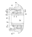
図2に示されているように、スクロール収容部3bは、第2駆動側軸部72cを収容する第2駆動側軸部収容部3b1を有し、第2駆動側軸部72cの外周面Xと、第2駆動側軸部収容部3b1の内周面Yとの間に第2駆動側軸受け14が設けられている。
シール部材16は、オイルシールであり、図2に示されているように、第2駆動側軸部収容部3b1の内周面Yに嵌入されたストッパリング19によって軸線方向の位置が規制されている。シール部材16は、樹脂製のシールリップ部16aを備えている。シールリップ部16aは、内周側に突出して第2駆動側軸部72cの外周面Xに当接するリップ先端部16a1を備えている。シールリップ部16aの背面側(外周側)には、円環状のばね16a2が設けられている。ばね16a2の弾性力によって、リップ先端部16a1が第2駆動側軸部72cの外周面Xの全周にわたって押し付けられるようになっている。
シール部材16と第2駆動側軸受け14とが対向するそれぞれの面すなわちシール部材16の側面Z及び第2駆動側軸受け14のW1面と、第2駆動側軸部72cの外周面Xと、第2駆動側軸部収容部3b1の内周面Yとで囲まれた空間Rに、潤滑剤17が封入されている。
シール部材16と第2駆動側軸受け14とが対向するそれぞれの面すなわちシール部材16の側面Z及び第2駆動側軸受け14のW1面と、第2駆動側軸部72cの外周面Xと、第2駆動側軸部収容部3b1の内周面Yとで囲まれた空間Rに、潤滑剤17が封入されている。
上記構成の両回転スクロール型圧縮機1は、以下のように動作する。
モータ5によって駆動軸6が駆動側回転軸線CL1回りに回転させられると、駆動軸6に接続された第1駆動側軸部7cも回転し、これにより駆動側スクロール部材70が駆動側回転軸線CL1回りに回転する。駆動側スクロール部材70が回転すると、駆動力がピンリング機構15を介して各サポート部材33,35から従動側スクロール部材90へと伝達され、従動側スクロール部材90が従動側回転軸線CL2回りに回転する。このとき、ピンリング機構15のピン部材15bが円形穴の内周面に対して接触しつつ移動することによって、両スクロール部材70,90が同じ方向に同一角速度で自転運動を行う。
両スクロール部材70,90が自転旋回運動を行うと、ハウジング3の吸入口から吸い込まれた空気が両スクロール部材70,90の外周側から吸入され、両スクロール部材70,90によって形成された圧縮室に取り込まれる。そして、第1駆動側壁体71bと第1従動側壁体91bとによって形成された圧縮室と、第2駆動側壁体72bと第2従動側壁体92bとによって形成された圧縮室とが別々に圧縮される。それぞれの圧縮室は中心側に移動するにしたがって容積が減少し、これに伴い空気が圧縮される。第1駆動側壁体71bと第1従動側壁体91bとによって圧縮された空気は、従動側端板91a,92aに形成された貫通孔90hを通り、第2駆動側壁体72bと第2従動側壁体92bとによって圧縮された空気と合流し、合流後の空気が吐出ポート72dを通り、ハウジング3の吐出口3dから外部へと吐出される。吐出された圧縮空気は、図示しない内燃機関へと導かれ、燃焼用空気として用いられる。
吐出ポート72dを出た後、吐出口3dから外部へ吐出される前の圧縮空気が占有する高圧空間HPと、ハウジング3の吸い込み口から吸い込まれ両スクロール部材70,90の外周側から吸入される吸入空気が占有する低圧空間LPとは、シール部材16及び潤滑剤17、第2駆動側軸受け14によって仕切られる。
シール部材16のシールリップ部16aの先端であるリップ先端部16a1は、シールリップ部16aに設けられたばね16a2によって、第2駆動側軸部72cの外周面Xに押し付けられ、リップ先端部16a1と第2駆動側軸部72cの外周面Xとの間の潤滑剤17により油膜が形成される。
シール部材16のシールリップ部16aの先端であるリップ先端部16a1は、シールリップ部16aに設けられたばね16a2によって、第2駆動側軸部72cの外周面Xに押し付けられ、リップ先端部16a1と第2駆動側軸部72cの外周面Xとの間の潤滑剤17により油膜が形成される。
本実施形態によれば、以下の作用効果を奏する。
第2駆動側軸部72cを回転支持する第2駆動側軸受け14を用いてシール部材16との間に空間Rを形成し、この空間Rに潤滑剤17を封入することとしたので、潤滑剤17を封入する空間を無駄なく構成することができる。例えば、シール部材を軸線方向に2つ並べて設置し、その間に潤滑剤を封入する構成に比べて、部品点数を減らすことができ、かつ第2駆動側軸部72cの軸線方向寸法を小さくできる。したがって、第2駆動側軸部72cの外周面Xをコンパクトにシールすることができ、圧縮空気の圧力損失を低減することができる。
特に、空気に潤滑油を含まないようにしたオイルレス圧縮機においても、シール部材16と第2駆動側軸受け14との間に封入された潤滑剤17によってシール部材16の潤滑が図られ、摩耗を低減することができる。
圧縮空気の需要先において、油分を含まないクリーンな圧縮空気が望まれる場合にオイルレス圧縮機が用いられても本実施形態のスクロール型圧縮機1であればシール部材の摩耗を低減することができる。
本実施形態は、以下のように変形してもよい。
[変形例1]
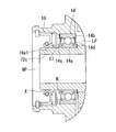
図3に示すように、第2駆動側軸受け14をシール形の玉軸受けとしても良い。第2駆動側軸受け14’は、両側面にそれぞれシール板14d,14eを備えている。これらシール板14d,14eによって、第2駆動側軸受け14’内の潤滑油の漏出が防止されている。シール板14d,14eは、円環状の板状とされており、鋼板にゴムを被覆したものが好適に用いられる。シール板14d,14eの外周側は、第2駆動側軸受け14’の外輪14bに固定されており、シール板14d,14eの内周側は内輪14aから離間しており非接触とされている。
このように、シール板14d,14eと内輪14aとが接触しない非接触式とすることで、接触による熱の発生等によるエネルギー損失を防ぎ、スクロール型圧縮機1のシステム効率の低下を防ぐことができる。
[変形例1]
図3に示すように、第2駆動側軸受け14をシール形の玉軸受けとしても良い。第2駆動側軸受け14’は、両側面にそれぞれシール板14d,14eを備えている。これらシール板14d,14eによって、第2駆動側軸受け14’内の潤滑油の漏出が防止されている。シール板14d,14eは、円環状の板状とされており、鋼板にゴムを被覆したものが好適に用いられる。シール板14d,14eの外周側は、第2駆動側軸受け14’の外輪14bに固定されており、シール板14d,14eの内周側は内輪14aから離間しており非接触とされている。
このように、シール板14d,14eと内輪14aとが接触しない非接触式とすることで、接触による熱の発生等によるエネルギー損失を防ぎ、スクロール型圧縮機1のシステム効率の低下を防ぐことができる。
[変形例2]
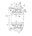
図4のように、第2駆動側軸受け14”は、図3に示したシール部材側W1のシール板14eを省略して、シール部材16と反対側W2のシール板14dのみとしても良い。
シール部材側W1の軸受け14”の側面は、シール部材16によって高圧空間HPの高圧が十分にシールされており、また潤滑剤17が充填されている空間Rに面しているので、シール部材側W1のシール板を省略することができる。一方、シール部材16と反対側W2の軸受け14”の側面は、ハウジング3内部に面するので、シール板14dを設置して潤滑剤の漏出を防ぐようになっている。
図4のように、第2駆動側軸受け14”は、図3に示したシール部材側W1のシール板14eを省略して、シール部材16と反対側W2のシール板14dのみとしても良い。
シール部材側W1の軸受け14”の側面は、シール部材16によって高圧空間HPの高圧が十分にシールされており、また潤滑剤17が充填されている空間Rに面しているので、シール部材側W1のシール板を省略することができる。一方、シール部材16と反対側W2の軸受け14”の側面は、ハウジング3内部に面するので、シール板14dを設置して潤滑剤の漏出を防ぐようになっている。
また、本実施形態では、シール部材16としてオイルシールを用いることとしたが、これに代えて、ガスケットや、メカニカルシール、ピストンリング、Oリング等のセルフシールパッキンと置き換えてもよい。ガスケットや、メカニカルシール、ピストンリング、Oリング等のセルフシールパッキンであるシール部材16と、第2駆動側軸部72cの外周面Xとの接触部において、潤滑剤17により、摩耗を低減することができる。
また、潤滑剤17は、半固体潤滑剤であるグリースを用いることとしたが、これに代えて、流体潤滑剤であり鉱油等で代表される潤滑油であってもよい。
上述したスクロール型圧縮機1は、スクロール部材7,9によって形成された圧縮室にて圧縮された圧縮空気に潤滑油を含まず、吐出ポート72dを経て吐出口3dから圧縮空気が外部へと吐出される、「オイルレス」、「オイルフリー」と称される圧縮機であってもよい。オイルレスの場合、高圧空間HP及び低圧空間LPを含むハウジング3内に潤滑油が含まれないため、シール部材16が摩耗するおそれがあるが、シール部材16と第2駆動側軸受け14との間に潤滑剤17を有することで、シール部材16の潤滑が図られ摩耗を低減することができる。
なお、上述した実施形態および各変形例では、過給機として両回転スクロール型圧縮機を用いることとしたが、本発明はこれに限定されるものではなく、流体を圧縮するものであれば広く利用することができ、例えば空調機械において使用される冷媒圧縮機として用いることもできる。また、本発明のスクロール型圧縮機1を鉄道車両用のブレーキシステムとして空気の力を利用した空制装置に適用することも可能である。
1 両回転スクロール型圧縮機(スクロール型圧縮機)
3 ハウジング
3a モータ収容部
3b スクロール収容部
3b1 第2駆動側軸部収容部
3c 冷却フィン
3d 吐出口
5 モータ(駆動部)
5a ステータ
5b ロータ
6 駆動軸
7c 第1駆動側軸部
11 第1駆動側軸受
14,14’,14” 第2駆動側軸受
14a 内輪
14b 外輪
14d シール板
14e シール板
15 ピンリング機構(同期駆動機構)
15b ピン部材
16 シール部材(オイルシール)
16a シールリップ部
16a1 リップ先端部
16a2 ばね
17 潤滑剤(グリース)
31 ボルト(壁体固定部)
33 第1サポート部材
33a 軸部
35 第2サポート部材
35a 軸部
37 第1サポート部材用軸受
38 第2サポート部材用軸受
70 駆動側スクロール部材
71 第1駆動側スクロール部
71a 第1駆動側端板
71b 第1駆動側壁体
72 第2駆動側スクロール部
72a 第2駆動側端板
72b 第2駆動側壁体
72c 第2駆動側軸部(吐出筒)
72d 吐出ポート
73 フランジ部
90 従動側スクロール部材
90h 貫通孔
91 第1従動側スクロール部
91a 第1従動側端板
91b 第1従動側壁体
92 第2従動側スクロール部
92a 第2従動側端板
92b 第2従動側壁体
CL1 駆動側回転軸線
CL2 従動側回転軸線
P 分割面
X 第2駆動側軸部の外周面
Y 第2駆動側軸部収容部の内周面
Z シール部材の側面
W1 第2駆動側軸受けのシール部材側
W2 第2駆動側軸受けのシール部材と反対側
HP 高圧空間
LP 低圧空間
R 空間
Claims (5)
- 作動流体を圧縮する圧縮室を有する一対のスクロール部材と、
前記一対のスクロール部材を収容するハウジングと、
圧縮された前記作動流体を前記圧縮室から吐き出すとともに前記ハウジングに対して軸線回りに回転する吐出筒と、
前記吐出筒を前記ハウジングに対して回転可能に支持する軸受けと、
前記吐出筒と前記ハウジングとの間に位置するシール部材とを備え、
前記軸受けと前記シール部材との間に形成される空間には、潤滑剤が封入されているスクロール型圧縮機。 - 前記軸受けは、両側面にシール板を備えた転がり軸受けとされ、前記シール板は、前記軸受けの外輪に固定されているとともに、前記軸受けの内輪に対して非接触とされている請求項1に記載のスクロール型圧縮機。
- 前記軸受けは、前記シール部材側と反対側の側面にシール板を備えた転がり軸受けとされ、前記シール部材側の側面にはシール板を備えていない請求項1に記載のスクロール型圧縮機。
- 前記シール部材は、オイルシールである請求項1から3のいずれかに記載のスクロール型圧縮機。
- 駆動部によって回転駆動される駆動軸を備え、
前記一対のスクロール部材として、前記駆動軸に連結されて回転運動を行う駆動側スクロール部材と、前記駆動側スクロール部材から動力が伝達されて回転運動を行う従動側スクロール部材と、を備えた両回転スクロール型圧縮機とされている請求項1から4のいずれかに記載のスクロール型圧縮機。
Priority Applications (3)
| Application Number | Priority Date | Filing Date | Title |
|---|---|---|---|
| EP18744177.9A EP3561303B1 (en) | 2017-01-27 | 2018-01-25 | Scroll compressor |
| US16/477,009 US20190353160A1 (en) | 2017-01-27 | 2018-01-25 | Scroll compressor |
| CN201880008098.1A CN110226040A (zh) | 2017-01-27 | 2018-01-25 | 涡旋型压缩机 |
Applications Claiming Priority (2)
| Application Number | Priority Date | Filing Date | Title |
|---|---|---|---|
| JP2017013326A JP2018119522A (ja) | 2017-01-27 | 2017-01-27 | スクロール型圧縮機 |
| JP2017-013326 | 2017-06-21 |
Publications (1)
| Publication Number | Publication Date |
|---|---|
| WO2018139500A1 true WO2018139500A1 (ja) | 2018-08-02 |
Family
ID=62979053
Family Applications (1)
| Application Number | Title | Priority Date | Filing Date |
|---|---|---|---|
| PCT/JP2018/002175 WO2018139500A1 (ja) | 2017-01-27 | 2018-01-25 | スクロール型圧縮機 |
Country Status (5)
| Country | Link |
|---|---|
| US (1) | US20190353160A1 (ja) |
| EP (1) | EP3561303B1 (ja) |
| JP (1) | JP2018119522A (ja) |
| CN (1) | CN110226040A (ja) |
| WO (1) | WO2018139500A1 (ja) |
Families Citing this family (1)
| Publication number | Priority date | Publication date | Assignee | Title |
|---|---|---|---|---|
| DE102020117373A1 (de) | 2020-07-01 | 2022-01-05 | Hanon Systems | Spiralverdichter zur Verdichtung eines Kältemittels und Verfahren zur Ölanreicherung und -verteilung |
Citations (5)
| Publication number | Priority date | Publication date | Assignee | Title |
|---|---|---|---|---|
| JPS62206282A (ja) * | 1986-03-07 | 1987-09-10 | Mitsubishi Electric Corp | スクロ−ル圧縮機 |
| JP2003202018A (ja) * | 2001-10-22 | 2003-07-18 | Nsk Ltd | 転がり軸受装置 |
| JP2005147356A (ja) * | 2003-11-19 | 2005-06-09 | Nok Corp | 密封装置 |
| JP2007023776A (ja) * | 2005-07-12 | 2007-02-01 | Shinji Kawazoe | スクロール流体機械 |
| JP2015001175A (ja) | 2013-06-14 | 2015-01-05 | アネスト岩田株式会社 | スクロール式流体機械 |
Family Cites Families (6)
| Publication number | Priority date | Publication date | Assignee | Title |
|---|---|---|---|---|
| CH675896A5 (ja) * | 1988-07-20 | 1990-11-15 | Aginfor Ag | |
| JPH08254213A (ja) * | 1995-03-17 | 1996-10-01 | Koyo Seiko Co Ltd | ウォ−タポンプ用軸受の密封装置 |
| JP5197157B2 (ja) * | 2008-05-27 | 2013-05-15 | 株式会社神戸製鋼所 | スクリュ流体機械 |
| JP2012207757A (ja) * | 2011-03-30 | 2012-10-25 | Keihin Corp | 圧縮機 |
| JP5925578B2 (ja) * | 2012-04-25 | 2016-05-25 | アネスト岩田株式会社 | スクロール膨張機 |
| JP5931563B2 (ja) * | 2012-04-25 | 2016-06-08 | アネスト岩田株式会社 | スクロール膨張機 |
-
2017
- 2017-01-27 JP JP2017013326A patent/JP2018119522A/ja active Pending
-
2018
- 2018-01-25 US US16/477,009 patent/US20190353160A1/en not_active Abandoned
- 2018-01-25 CN CN201880008098.1A patent/CN110226040A/zh active Pending
- 2018-01-25 WO PCT/JP2018/002175 patent/WO2018139500A1/ja unknown
- 2018-01-25 EP EP18744177.9A patent/EP3561303B1/en active Active
Patent Citations (5)
| Publication number | Priority date | Publication date | Assignee | Title |
|---|---|---|---|---|
| JPS62206282A (ja) * | 1986-03-07 | 1987-09-10 | Mitsubishi Electric Corp | スクロ−ル圧縮機 |
| JP2003202018A (ja) * | 2001-10-22 | 2003-07-18 | Nsk Ltd | 転がり軸受装置 |
| JP2005147356A (ja) * | 2003-11-19 | 2005-06-09 | Nok Corp | 密封装置 |
| JP2007023776A (ja) * | 2005-07-12 | 2007-02-01 | Shinji Kawazoe | スクロール流体機械 |
| JP2015001175A (ja) | 2013-06-14 | 2015-01-05 | アネスト岩田株式会社 | スクロール式流体機械 |
Also Published As
| Publication number | Publication date |
|---|---|
| EP3561303B1 (en) | 2020-12-30 |
| JP2018119522A (ja) | 2018-08-02 |
| EP3561303A4 (en) | 2019-12-18 |
| CN110226040A (zh) | 2019-09-10 |
| US20190353160A1 (en) | 2019-11-21 |
| EP3561303A1 (en) | 2019-10-30 |
Similar Documents
| Publication | Publication Date | Title |
|---|---|---|
| JP5017052B2 (ja) | スクリュ流体機械 | |
| JP2006009792A (ja) | 回転式圧縮機 | |
| US20130177465A1 (en) | Compressor with compliant thrust bearing | |
| WO2018139543A1 (ja) | スクロール型圧縮機およびその組立方法 | |
| WO2012096056A1 (ja) | スクロール流体機械 | |
| CN111684159B (zh) | 双旋转涡旋型压缩机及其组装方法 | |
| CN110337543B (zh) | 双旋转涡旋型压缩机 | |
| WO2018139500A1 (ja) | スクロール型圧縮機 | |
| JP4889469B2 (ja) | 流体機械 | |
| JP4684832B2 (ja) | 気体圧縮機 | |
| WO2009090888A1 (ja) | 回転式流体機械 | |
| WO2018139538A1 (ja) | 両回転スクロール型圧縮機及びその組立方法 | |
| JP7325975B2 (ja) | 開放型圧縮機 | |
| JP6167319B2 (ja) | 回転ポンプの軸シール構造 | |
| CN110300853B (zh) | 双旋转涡旋型压缩机 | |
| JP2010112174A (ja) | ロータリ圧縮機 | |
| WO2018139501A1 (ja) | スクロール型圧縮機 | |
| KR101292410B1 (ko) | 공기 압축/팽창기 | |
| JP6963452B2 (ja) | 開放型圧縮機 | |
| JP2016205212A (ja) | 気体圧縮機 | |
| US1349199A (en) | Compressor | |
| JP2020193567A (ja) | ロータリ圧縮機 | |
| JP2009108810A (ja) | ロータリ圧縮機 | |
| JP2006046267A (ja) | 圧縮機 | |
| JP2006046268A (ja) | 圧縮機 |
Legal Events
| Date | Code | Title | Description |
|---|---|---|---|
| 121 | Ep: the epo has been informed by wipo that ep was designated in this application |
Ref document number: 18744177 Country of ref document: EP Kind code of ref document: A1 |
|
| ENP | Entry into the national phase |
Ref document number: 2018744177 Country of ref document: EP Effective date: 20190723 |
|
| NENP | Non-entry into the national phase |
Ref country code: DE |