EP3561303B1 - Scroll compressor - Google Patents
Scroll compressor Download PDFInfo
- Publication number
- EP3561303B1 EP3561303B1 EP18744177.9A EP18744177A EP3561303B1 EP 3561303 B1 EP3561303 B1 EP 3561303B1 EP 18744177 A EP18744177 A EP 18744177A EP 3561303 B1 EP3561303 B1 EP 3561303B1
- Authority
- EP
- European Patent Office
- Prior art keywords
- driving
- seal
- scroll
- bearing
- scroll compressor
- Prior art date
- Legal status (The legal status is an assumption and is not a legal conclusion. Google has not performed a legal analysis and makes no representation as to the accuracy of the status listed.)
- Active
Links
- 239000000314 lubricant Substances 0.000 claims description 36
- 230000002093 peripheral effect Effects 0.000 claims description 25
- 239000012530 fluid Substances 0.000 claims description 16
- 230000006835 compression Effects 0.000 claims description 11
- 238000007906 compression Methods 0.000 claims description 11
- 238000005096 rolling process Methods 0.000 claims description 5
- 239000003921 oil Substances 0.000 description 17
- 230000004308 accommodation Effects 0.000 description 14
- 230000007246 mechanism Effects 0.000 description 7
- 230000004048 modification Effects 0.000 description 5
- 238000012986 modification Methods 0.000 description 5
- 238000002485 combustion reaction Methods 0.000 description 4
- 239000004519 grease Substances 0.000 description 3
- 238000005461 lubrication Methods 0.000 description 3
- 238000001816 cooling Methods 0.000 description 2
- 230000006866 deterioration Effects 0.000 description 2
- 230000000694 effects Effects 0.000 description 2
- 238000012856 packing Methods 0.000 description 2
- 238000007789 sealing Methods 0.000 description 2
- 239000007787 solid Substances 0.000 description 2
- 230000001360 synchronised effect Effects 0.000 description 2
- 239000002699 waste material Substances 0.000 description 2
- 229910000831 Steel Inorganic materials 0.000 description 1
- 230000001419 dependent effect Effects 0.000 description 1
- 239000002480 mineral oil Substances 0.000 description 1
- 235000010446 mineral oil Nutrition 0.000 description 1
- 239000003507 refrigerant Substances 0.000 description 1
- 230000001105 regulatory effect Effects 0.000 description 1
- 239000011347 resin Substances 0.000 description 1
- 229920005989 resin Polymers 0.000 description 1
- 230000003068 static effect Effects 0.000 description 1
- 239000010959 steel Substances 0.000 description 1
Images


Classifications
-
- F—MECHANICAL ENGINEERING; LIGHTING; HEATING; WEAPONS; BLASTING
- F04—POSITIVE - DISPLACEMENT MACHINES FOR LIQUIDS; PUMPS FOR LIQUIDS OR ELASTIC FLUIDS
- F04C—ROTARY-PISTON, OR OSCILLATING-PISTON, POSITIVE-DISPLACEMENT MACHINES FOR LIQUIDS; ROTARY-PISTON, OR OSCILLATING-PISTON, POSITIVE-DISPLACEMENT PUMPS
- F04C27/00—Sealing arrangements in rotary-piston pumps specially adapted for elastic fluids
- F04C27/008—Sealing arrangements in rotary-piston pumps specially adapted for elastic fluids for other than working fluid, i.e. the sealing arrangements are not between working chambers of the machine
-
- F—MECHANICAL ENGINEERING; LIGHTING; HEATING; WEAPONS; BLASTING
- F04—POSITIVE - DISPLACEMENT MACHINES FOR LIQUIDS; PUMPS FOR LIQUIDS OR ELASTIC FLUIDS
- F04C—ROTARY-PISTON, OR OSCILLATING-PISTON, POSITIVE-DISPLACEMENT MACHINES FOR LIQUIDS; ROTARY-PISTON, OR OSCILLATING-PISTON, POSITIVE-DISPLACEMENT PUMPS
- F04C18/00—Rotary-piston pumps specially adapted for elastic fluids
- F04C18/02—Rotary-piston pumps specially adapted for elastic fluids of arcuate-engagement type, i.e. with circular translatory movement of co-operating members, each member having the same number of teeth or tooth-equivalents
- F04C18/0207—Rotary-piston pumps specially adapted for elastic fluids of arcuate-engagement type, i.e. with circular translatory movement of co-operating members, each member having the same number of teeth or tooth-equivalents both members having co-operating elements in spiral form
- F04C18/023—Rotary-piston pumps specially adapted for elastic fluids of arcuate-engagement type, i.e. with circular translatory movement of co-operating members, each member having the same number of teeth or tooth-equivalents both members having co-operating elements in spiral form where both members are moving
- F04C18/0238—Rotary-piston pumps specially adapted for elastic fluids of arcuate-engagement type, i.e. with circular translatory movement of co-operating members, each member having the same number of teeth or tooth-equivalents both members having co-operating elements in spiral form where both members are moving with symmetrical double wraps
-
- F—MECHANICAL ENGINEERING; LIGHTING; HEATING; WEAPONS; BLASTING
- F04—POSITIVE - DISPLACEMENT MACHINES FOR LIQUIDS; PUMPS FOR LIQUIDS OR ELASTIC FLUIDS
- F04C—ROTARY-PISTON, OR OSCILLATING-PISTON, POSITIVE-DISPLACEMENT MACHINES FOR LIQUIDS; ROTARY-PISTON, OR OSCILLATING-PISTON, POSITIVE-DISPLACEMENT PUMPS
- F04C18/00—Rotary-piston pumps specially adapted for elastic fluids
- F04C18/02—Rotary-piston pumps specially adapted for elastic fluids of arcuate-engagement type, i.e. with circular translatory movement of co-operating members, each member having the same number of teeth or tooth-equivalents
- F04C18/0207—Rotary-piston pumps specially adapted for elastic fluids of arcuate-engagement type, i.e. with circular translatory movement of co-operating members, each member having the same number of teeth or tooth-equivalents both members having co-operating elements in spiral form
- F04C18/023—Rotary-piston pumps specially adapted for elastic fluids of arcuate-engagement type, i.e. with circular translatory movement of co-operating members, each member having the same number of teeth or tooth-equivalents both members having co-operating elements in spiral form where both members are moving
-
- F—MECHANICAL ENGINEERING; LIGHTING; HEATING; WEAPONS; BLASTING
- F04—POSITIVE - DISPLACEMENT MACHINES FOR LIQUIDS; PUMPS FOR LIQUIDS OR ELASTIC FLUIDS
- F04C—ROTARY-PISTON, OR OSCILLATING-PISTON, POSITIVE-DISPLACEMENT MACHINES FOR LIQUIDS; ROTARY-PISTON, OR OSCILLATING-PISTON, POSITIVE-DISPLACEMENT PUMPS
- F04C2/00—Rotary-piston machines or pumps
- F04C2/02—Rotary-piston machines or pumps of arcuate-engagement type, i.e. with circular translatory movement of co-operating members, each member having the same number of teeth or tooth-equivalents
- F04C2/04—Rotary-piston machines or pumps of arcuate-engagement type, i.e. with circular translatory movement of co-operating members, each member having the same number of teeth or tooth-equivalents of internal axis type
- F04C2/045—Rotary-piston machines or pumps of arcuate-engagement type, i.e. with circular translatory movement of co-operating members, each member having the same number of teeth or tooth-equivalents of internal axis type having a C-shaped piston
-
- F—MECHANICAL ENGINEERING; LIGHTING; HEATING; WEAPONS; BLASTING
- F04—POSITIVE - DISPLACEMENT MACHINES FOR LIQUIDS; PUMPS FOR LIQUIDS OR ELASTIC FLUIDS
- F04C—ROTARY-PISTON, OR OSCILLATING-PISTON, POSITIVE-DISPLACEMENT MACHINES FOR LIQUIDS; ROTARY-PISTON, OR OSCILLATING-PISTON, POSITIVE-DISPLACEMENT PUMPS
- F04C27/00—Sealing arrangements in rotary-piston pumps specially adapted for elastic fluids
- F04C27/008—Sealing arrangements in rotary-piston pumps specially adapted for elastic fluids for other than working fluid, i.e. the sealing arrangements are not between working chambers of the machine
- F04C27/009—Shaft sealings specially adapted for pumps
-
- F—MECHANICAL ENGINEERING; LIGHTING; HEATING; WEAPONS; BLASTING
- F04—POSITIVE - DISPLACEMENT MACHINES FOR LIQUIDS; PUMPS FOR LIQUIDS OR ELASTIC FLUIDS
- F04C—ROTARY-PISTON, OR OSCILLATING-PISTON, POSITIVE-DISPLACEMENT MACHINES FOR LIQUIDS; ROTARY-PISTON, OR OSCILLATING-PISTON, POSITIVE-DISPLACEMENT PUMPS
- F04C29/00—Component parts, details or accessories of pumps or pumping installations, not provided for in groups F04C18/00 - F04C28/00
- F04C29/02—Lubrication; Lubricant separation
-
- F—MECHANICAL ENGINEERING; LIGHTING; HEATING; WEAPONS; BLASTING
- F04—POSITIVE - DISPLACEMENT MACHINES FOR LIQUIDS; PUMPS FOR LIQUIDS OR ELASTIC FLUIDS
- F04C—ROTARY-PISTON, OR OSCILLATING-PISTON, POSITIVE-DISPLACEMENT MACHINES FOR LIQUIDS; ROTARY-PISTON, OR OSCILLATING-PISTON, POSITIVE-DISPLACEMENT PUMPS
- F04C29/00—Component parts, details or accessories of pumps or pumping installations, not provided for in groups F04C18/00 - F04C28/00
- F04C29/04—Heating; Cooling; Heat insulation
- F04C29/042—Heating; Cooling; Heat insulation by injecting a fluid
-
- F—MECHANICAL ENGINEERING; LIGHTING; HEATING; WEAPONS; BLASTING
- F04—POSITIVE - DISPLACEMENT MACHINES FOR LIQUIDS; PUMPS FOR LIQUIDS OR ELASTIC FLUIDS
- F04C—ROTARY-PISTON, OR OSCILLATING-PISTON, POSITIVE-DISPLACEMENT MACHINES FOR LIQUIDS; ROTARY-PISTON, OR OSCILLATING-PISTON, POSITIVE-DISPLACEMENT PUMPS
- F04C29/00—Component parts, details or accessories of pumps or pumping installations, not provided for in groups F04C18/00 - F04C28/00
- F04C29/12—Arrangements for admission or discharge of the working fluid, e.g. constructional features of the inlet or outlet
-
- F—MECHANICAL ENGINEERING; LIGHTING; HEATING; WEAPONS; BLASTING
- F16—ENGINEERING ELEMENTS AND UNITS; GENERAL MEASURES FOR PRODUCING AND MAINTAINING EFFECTIVE FUNCTIONING OF MACHINES OR INSTALLATIONS; THERMAL INSULATION IN GENERAL
- F16J—PISTONS; CYLINDERS; SEALINGS
- F16J15/00—Sealings
- F16J15/16—Sealings between relatively-moving surfaces
- F16J15/32—Sealings between relatively-moving surfaces with elastic sealings, e.g. O-rings
- F16J15/3204—Sealings between relatively-moving surfaces with elastic sealings, e.g. O-rings with at least one lip
-
- F—MECHANICAL ENGINEERING; LIGHTING; HEATING; WEAPONS; BLASTING
- F04—POSITIVE - DISPLACEMENT MACHINES FOR LIQUIDS; PUMPS FOR LIQUIDS OR ELASTIC FLUIDS
- F04C—ROTARY-PISTON, OR OSCILLATING-PISTON, POSITIVE-DISPLACEMENT MACHINES FOR LIQUIDS; ROTARY-PISTON, OR OSCILLATING-PISTON, POSITIVE-DISPLACEMENT PUMPS
- F04C15/00—Component parts, details or accessories of machines, pumps or pumping installations, not provided for in groups F04C2/00 - F04C14/00
- F04C15/0088—Lubrication
-
- F—MECHANICAL ENGINEERING; LIGHTING; HEATING; WEAPONS; BLASTING
- F04—POSITIVE - DISPLACEMENT MACHINES FOR LIQUIDS; PUMPS FOR LIQUIDS OR ELASTIC FLUIDS
- F04C—ROTARY-PISTON, OR OSCILLATING-PISTON, POSITIVE-DISPLACEMENT MACHINES FOR LIQUIDS; ROTARY-PISTON, OR OSCILLATING-PISTON, POSITIVE-DISPLACEMENT PUMPS
- F04C2240/00—Components
- F04C2240/50—Bearings
- F04C2240/56—Bearing bushings or details thereof
Definitions
- the present disclosure relates to a scroll compressor suitably used for, for example, a double rotating scroll compressor.
- a double rotating scroll compressor has been well-known (refer to PTL 1).
- Such a double rotating scroll compressor includes a seal plate on a front end surface of a discharge cylinder.
- the seal plate seals high-pressure side occupied by compressed working fluid and low-pressure side that is an internal space of a housing.
- a seal plate 48 sandwiched between a front end surface of a discharge cylinder 46 and a boss portion 50 is compressed in an axis direction to achieve sealing (reference numerals are those described in PTL 1).
- sealability may be deteriorated.
- the present disclosure is made in consideration of such circumstances, and an object of the present disclosure is to provide a scroll compressor that makes it possible to reduce the axial dimension of the discharge cylinder rotated around the axis while supplying a lubricant when the outer peripheral surface of the discharge cylinder is sealed.
- the compressor includes paired scroll members that include a compression chamber to compress working fluid, a housing that houses the paired scroll members, a discharge cylinder that discharges the compressed working fluid from the compression chamber and is rotated around an axis with respect to the housing, a bearing that rotatably supports the discharge cylinder with respect to the housing, and a seal member that is located between the discharge cylinder and the housing.
- a lubricant is enclosed in a space formed between the bearing and the seal member.
- the space is formed between the seal member and the bearing that rotatably supports the discharge cylinder, and the lubricant is enclosed in the space.
- the scroll compressor according to the present disclosure can reduce wear of the seal member.
- the bearing may be a rolling bearing including seal plates on respective side surfaces, and the seal plates may be fixed to an outer ring of the bearing and may be not in contact with an inner ring of the bearing.
- the bearing may be a rolling bearing including a seal plate on a side surface on side opposite to the seal member side, and may not include a seal plate on a side surface on the seal member side.
- the side surface of the bearing on the seal member side faces the space in which high-pressure working fluid is sufficiently sealed by the seal member and in which the lubricant is enclosed. This allows for omission of the seal plate on the seal member side.
- a side surface of the bearing on the side opposite to the seal member faces an inside of the housing. Therefore, the seal plate is disposed to prevent leakage of the lubricant.
- the seal member may be an oil seal.
- the lubricant is provided between the oil seal and the bearing, which makes it possible to reduce wear of the oil seal.
- the scroll compressor according to the present disclosure may further include a driving shaft that is rotationally driven by a driving unit, and the scroll compressor may be configured as a double rotating scroll compressor that includes a driving-side scroll member and a driven-side scroll member as the paired scroll members.
- the driving-side scroll member is coupled to the driving shaft and performs rotational movement, and the driven-side scroll member receives power transmitted from the driving-side scroll member to perform rotational movement.
- Fig. 1 illustrates a double rotating scroll compressor (scroll compressor) 1.
- the double rotating scroll compressor 1 can be used as, for example, a supercharger that compresses combustion air (fluid) to be supplied to an internal combustion engine such as a vehicle engine.
- the double rotating scroll compressor 1 includes a housing 3, a motor (driving unit) 5 accommodated on one end side in the housing 3, and a driving-side scroll member 70 and a driven-side scroll member 90 that are accommodated on the other end side in the housing 3.
- the housing 3 has a substantially cylindrical shape, and includes a motor accommodation portion (first housing) 3a that accommodates the motor 5, and a scroll accommodation portion (second housing) 3b that accommodates the scroll members 70 and 90.
- a cooling fin 3c to cool the motor 5 is provided on an outer periphery of the motor accommodation portion 3a.
- a discharge opening 3d from which compressed air (working fluid) is discharged is provided at an end part of the scroll accommodation portion 3b. Note that, although not illustrated in Fig. 1 , the housing 3 includes an air suction opening from which air (working fluid) is sucked in.
- the scroll accommodation portion 3b of the housing 3 is divided at a division surface P that is located at a substantially center in an axis direction of the scroll members 70 and 90.
- the housing 3 includes a flange portion (not illustrated) that protrudes outward at a predetermined position in a circumferential direction. A bolt or the like as a fastening means is inserted into and fixed to the flange portion, which results in fastening at the division surface P.
- the motor 5 is driven by being supplied with power from an unillustrated power supply source. Rotation of the motor 5 is controlled by an instruction from an unillustrated control unit.
- a stator 5a of the motor 5 is fixed to an inner periphery of the housing 3.
- a rotor 5b of the motor 5 rotates around a driving-side rotation axis CL1.
- a driving shaft 6 that extends on the driving-side rotation axis CL1 is connected to the rotor 5b.
- the driving shaft 6 is connected to a first driving-side shaft portion 7c of the driving-side scroll member 70.
- the driving-side scroll member 70 includes a first driving-side scroll portion 71 on the motor 5 side, and a second driving-side scroll portion 72 on the discharge opening 3d side.
- the first driving-side scroll portion 71 includes a first driving-side end plate 71a and first driving-side walls 71b.
- the first driving-side end plate 71a is connected to the first driving-side shaft portion 7c connected to the driving shaft 6, and extends in a direction orthogonal to the driving-side rotation axis CL1.
- the first driving-side shaft portion 7c is provided so as to be rotatable with respect to the housing 3 through a first driving-side bearing 11 that is a ball bearing.
- the first driving-side end plate 71a has a substantially disc shape in a planar view.
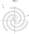
- the first driving-side wall 71b formed in a spiral shape is provided on the first driving-side end plate 71a.
- the three lines of first driving-side walls 71b are disposed at an equal interval around the driving-side rotation axis CL1 (see Fig. 5 ).
- the second driving-side scroll portion 72 includes a second driving-side end plate 72a and second driving-side walls 72b.
- the second driving-side walls 72b are each formed in a spiral shape as with the above-described first driving-side walls 71b.
- a second driving-side shaft portion (discharge cylinder) 72c that extends in the driving-side rotation axis CL1 and has a cylindrical shape is connected to the second driving-side end plate 72a.
- the second driving-side shaft portion 72c is provided so as to be rotatable with respect to the housing 3 through a second driving-side bearing 14 that is a ball bearing.
- the second driving-side end plate 72a includes a discharge port 72d extending along the driving-side rotation axis CL1.
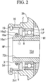
- a seal member 16 is provided on downstream side of the second driving-side bearing 14 in a discharge direction of the compressed air, namely, on front end side that is a free end of the second driving-side shaft portion 72c, between the second driving-side shaft portion 72c and the housing 3.
- the seal member 16 and the second driving-side bearing 14 are disposed at a predetermined interval in the driving-side rotation axis CL1 direction, and a space R is provided therebetween.
- a lubricant 17 that is grease as, for example, semi-solid lubricant is enclosed in the space R.
- the first driving-side scroll portion 71 and the second driving-side scroll portion 72 are fixed while front ends (free ends) of the walls 71b and 72b corresponding to each other face each other.
- the first driving-side scroll portion 71 and the second driving-side scroll portion 72 are fixed by bolts (wall fixing parts) 31 that are fastened to respective flange portions 73 provided at a plurality of positions in the circumferential direction.
- the flange portions 73 are provided so as to protrude outward in a radial direction.
- the driven-side scroll member 90 includes a first driven-side scroll portion 91 and a second driven-side scroll portion 92.
- Driven-side end plates 91a and 92a are located at a substantially center of the driven-side scroll member 90 in the axis direction (horizontal direction in figure).
- the driven-side end plates 91a and 92a are fixed while rear surfaces (other side surfaces) of the respective driven-side end plates 91a and 92a are superimposed and in contact with each other.
- the fixing is performed by a bolt, a pin, etc.
- the through hole 90h is provided at a center of each of the driven-side end plates 91a and 92a, and causes the compressed air to flow toward the discharge port 72d.
- the first driven-side walls 91b are provided on one side surface of the first driven-side end plate 91a, and the second driven-side walls 92b are provided on one side surface of the second driven-side end plate 92a.
- the first driven-side walls 91b provided on the motor 5 side from the first driven-side end plate 91a engage with the first driving-side walls 71b of the first driving-side scroll portion 71.
- the second driven-side walls 92b provided on the discharge opening 3d side from the second driven-side end plate 92a engage with the second driving-side walls 72b of the second driving-side scroll portion 72.
- the support members 33 and 35 described later are fixed to the outer peripheries of the first driven-side walls 91b.
- the second driven-side walls 92b also have the similar configuration.
- the first support member 33 and the second support member 35 are provided at the respective ends of the driven-side scroll member 90 in the axis direction (horizontal direction in figure).
- the first support member 33 is disposed on the motor 5 side, and the second support member 35 is disposed on the discharge opening 3d side.
- the first support member 33 is fixed to the front ends (free ends) of the first driven-side walls 91b, and the second support member 35 is fixed to the front ends (free ends) of the second driven-side walls 92b.
- the shaft portion 33a is provided on the center axis side of the first support member 33, and the shaft portion 33a is fixed to the housing 3 through the first support member bearing 37.
- the shaft portion 35a is provided on the center axis side of the second support member 35, and the shaft portion 35a is fixed to the housing 3 through the second support member bearing 38.
- the driven-side scroll member 90 rotates around the driven-side rotation axis CL2 through the support members 33 and 35.
- the pin-ring mechanism (synchronous driving mechanism) 15 is provided between the first support member 33 and the first driving-side end plate 71a. More specifically, a circular hole is provided in the first driving-side end plate 71a, and the pin member 15b is provided on the first support member 33.
- the pin-ring mechanism 15 transmits the driving force from the driving-side scroll member 70 to the driven-side scroll member 90, and causes the scroll members 70 and 90 to perform rotational movement in the same direction at the same angular velocity.
- the scroll accommodation portion 3b includes a second driving-side shaft portion accommodation portion 3b1 that accommodates the second driving-side shaft portion 72c, and the second driving-side bearing 14 is provided between an outer peripheral surface X of the second driving-side shaft portion 72c and an inner peripheral surface Y of the second driving-side shaft portion accommodation portion 3b1.
- the seal member 16 is an oil seal, and a position of the seal member 16 in the axis direction is regulated by a stopper ring 19 that is fitted in the inner peripheral surface Y of the second driving-side shaft portion accommodation portion 3b1 as illustrated in Fig. 2 .
- the seal member 16 includes a seal lip portion 16a made of a resin.
- the seal lip portion 16a includes a lip front end part 16a1 that protrudes to the inner peripheral side and comes into contact with the outer peripheral surface X of the second driving-side shaft portion 72c.
- An annular spring 16a2 is provided on rear-surface side (outer peripheral side) of the seal lip portion 16a. The lip front end part 16a1 is pressed against the entire circumference of the outer peripheral surface X of the second driving-side shaft portion 72c by elastic force of the spring 16a2.
- the lubricant 17 is enclosed in the space R surrounded by a surface of the seal member 16 and a surface of the second driving-side bearing 14 facing each other, namely, a side surface Z of the seal member 16 and a surface W1 of the second driving-side bearing 14, the outer peripheral surface X of the second driving-side shaft portion 72c, and the inner peripheral surface Y of the second driving-side shaft portion accommodation portion 3b1.
- the double rotating scroll compressor 1 including the above-described configuration operates in the following manner.
- the driving shaft 6 rotates around the driving-side rotation axis CL1 by the motor 5
- the first driving-side shaft portion 7c connected to the driving shaft 6 also rotates, and the driving-side scroll member 70 accordingly rotates around the driving-side rotation axis CL1.
- the driving-side scroll member 70 rotates, the driving force is transmitted from the support members 33 and 35 to the driven-side scroll member 90 through the pin-ring mechanisms 15, and the driven-side scroll member 90 rotates around the driven-side rotation axis CL2.
- the pin member 15b of the pin-ring mechanism 15 moves while being in contact with the inner peripheral surface of the circular hole, the both scroll members 70 and 90 perform rotational movement in the same direction at the same angular velocity.
- the air sucked through the air suction opening of the housing 3 is sucked in from outer peripheral side of each of the scroll members 70 and 90, and is taken into the compression chambers formed by the scroll members 70 and 90. Further, compression is separately performed in the compression chambers formed by the first driving-side walls 71b and the first driven-side walls 91b and in the compression chambers formed by the second driving-side walls 72b and the second driven-side walls 92b. A volume of each of the compression chambers is reduced as each of the compression chambers moves toward the center, which compresses the air.
- the air compressed by the first driving-side walls 71b and the first driven-side walls 91b passes through the through holes 90h provided in the driven-side end plates 91a and 92a, and is joined with the air compressed by the second driving-side walls 72b and the second driven-side walls 92b.
- the resultant air passes through the discharge port 72d and is discharged to outside from the discharge opening 3d of the housing 3.
- the discharged compressed air is guided to an unillustrated internal combustion engine, and is used as combustion air.
- a high-pressure space HP occupied by the compressed air that has been discharged from the discharge port 72d but before being discharged to the outside from the discharge opening 3d and a low-pressure space LP occupied by sucked air that is sucked from the suction opening of the housing 3 and is taken in from the outer peripheral side of the both scroll members 70 and 90 are partitioned by the seal member 16, the lubricant 17, and the second driving-side bearing 14.
- the lip front end part 16a1 that is a front end of the seal lip portion 16a of the seal member 16 is pressed against the outer peripheral surface X of the second driving-side shaft portion 72c by the spring 16a2 provided on the seal lip portion 16a, and an oil film is formed by the lubricant 17 between the lip front end part 16a1 and the outer peripheral surface X of the second driving-side shaft portion 72c.
- the present embodiment achieves the following action effects.
- the space R is formed between the seal member 16 and the second driving-side bearing 14 that rotatably supports the second driving-side shaft portion 72c, and the lubricant 17 is enclosed in the space R. Therefore, it is possible to configure the space in which the lubricant 17 is enclosed, without waste. For example, as compared with a configuration in which two seal members are disposed side by side in the axis direction and the lubricant is enclosed in a space between the seal members, it is possible to reduce the number of components and to reduce an axial dimension of the second driving-side shaft portion 72c. Accordingly, the outer peripheral surface X of the second driving-side shaft portion 72c can be sealed in compact, which makes it possible to reduce pressure loss of the compressed air.
- lubrication of the seal member 16 is achieved by the lubricant 17 enclosed between the seal member 16 and the second driving-side bearing 14, which allows for reduction of wear.
- the scroll compressor 1 can reduce wear of the seal member.
- the present embodiment may be modified in the following manner.
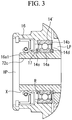
- a sealed ball bearing may be used as the second driving-side bearing 14.
- a second driving-side bearing 14' includes seal plates 14d and 14e on respective side surfaces. The seal plates 14d and 14e prevent leakage of the lubricant oil inside the second driving-side bearing 14'.
- Each of the seal plates 14d and 14e is formed in an annular plate shape, and a seal plate in which a steel plate is coated with rubber is suitably used for each of the seal plates 14d and 14e.
- each of the seal plates 14d and 14e is fixed to an outer ring 14b of the second driving-side bearing 14', and an inner periphery of each of the seal plates 14d and 14e is separated from an inner ring 14a so as not to come into contact with the inner ring 14a.
- a non-contact configuration in which the seal plates 14d and 14e do not come into contact with the inner ring 14a makes it possible to prevent energy loss due to generation of heat and the like due to the contact, thereby preventing deterioration of system efficiency of the scroll compressor 1.
- a second driving-side bearing 14" may include only the seal plate 14d on side W2 opposite to the seal member 16 without the seal plate 14e on the seal member side W1 illustrated in Fig. 3 .
- a side surface of the bearing 14" on the seal member side W1 faces the space R in which the high-pressure air of the high-pressure space HP is sufficiently sealed by the seal member 16 and in which the lubricant 17 is enclosed. This allows for omission of the seal plate on the seal member side W1.
- a side surface of the bearing 14" on the side W2 opposite to the seal member 16 faces the inside of the housing 3. Therefore, the seal plate 14d is disposed to prevent leakage of the lubricant.
- the oil seal is used as the seal member 16; however, the oil seal may be replaced with a self-seal packing such as a gasket, a mechanical seal, a piston ring, and an O-ring.
- the lubricant 17 can reduce wear at a contact portion between the seal member 16 that is a self-seal packing such as a gasket, a mechanical seal, a piston ring, and an O-ring and the outer peripheral surface X of the second driving-side shaft portion 72c.
- lubricant oil that is fluid lubricant and is represented by mineral oil may be used.
- the above-described scroll compressor 1 may be an "oilless" or “oil-free” compressor in which the compressed air that has been compressed in the compression chamber formed by the scroll members 7 and 9 contains no lubricant oil, and the compressed air is discharged to the outside from the discharge opening 3d through the discharge port 72d.
- the seal member 16 may be worn down because no lubricant oil is contained in the housing 3 including the high-pressure space HP and the low-pressure space LP; however, providing the lubricant 17 to the space between the seal member 16 and the second driving-side bearing 14 makes it possible to achieve lubrication of the seal member 16 and to reduce wear of the seal member 16.
- the double rotating scroll compressor is used as the supercharger; however, the present disclosure is not limited thereto.
- the double rotating scroll compressor is widely used to compress fluid, and for example, can be used as a refrigerant compressor used in air conditioner.
- the scroll compressor 1 according to the present disclosure is applicable to an air brake device using air force, as a brake system for a railway vehicle.
Landscapes
- Engineering & Computer Science (AREA)
- General Engineering & Computer Science (AREA)
- Mechanical Engineering (AREA)
- Rotary Pumps (AREA)
- Applications Or Details Of Rotary Compressors (AREA)
- Sealing With Elastic Sealing Lips (AREA)
Applications Claiming Priority (2)
| Application Number | Priority Date | Filing Date | Title |
|---|---|---|---|
| JP2017013326A JP2018119522A (ja) | 2017-01-27 | 2017-01-27 | スクロール型圧縮機 |
| PCT/JP2018/002175 WO2018139500A1 (ja) | 2017-01-27 | 2018-01-25 | スクロール型圧縮機 |
Publications (3)
| Publication Number | Publication Date |
|---|---|
| EP3561303A1 EP3561303A1 (en) | 2019-10-30 |
| EP3561303A4 EP3561303A4 (en) | 2019-12-18 |
| EP3561303B1 true EP3561303B1 (en) | 2020-12-30 |
Family
ID=62979053
Family Applications (1)
| Application Number | Title | Priority Date | Filing Date |
|---|---|---|---|
| EP18744177.9A Active EP3561303B1 (en) | 2017-01-27 | 2018-01-25 | Scroll compressor |
Country Status (5)
| Country | Link |
|---|---|
| US (1) | US20190353160A1 (ja) |
| EP (1) | EP3561303B1 (ja) |
| JP (1) | JP2018119522A (ja) |
| CN (1) | CN110226040A (ja) |
| WO (1) | WO2018139500A1 (ja) |
Families Citing this family (1)
| Publication number | Priority date | Publication date | Assignee | Title |
|---|---|---|---|---|
| DE102020117373A1 (de) | 2020-07-01 | 2022-01-05 | Hanon Systems | Spiralverdichter zur Verdichtung eines Kältemittels und Verfahren zur Ölanreicherung und -verteilung |
Family Cites Families (11)
| Publication number | Priority date | Publication date | Assignee | Title |
|---|---|---|---|---|
| JPS62206282A (ja) * | 1986-03-07 | 1987-09-10 | Mitsubishi Electric Corp | スクロ−ル圧縮機 |
| CH675896A5 (ja) * | 1988-07-20 | 1990-11-15 | Aginfor Ag | |
| JPH08254213A (ja) * | 1995-03-17 | 1996-10-01 | Koyo Seiko Co Ltd | ウォ−タポンプ用軸受の密封装置 |
| JP2003202018A (ja) * | 2001-10-22 | 2003-07-18 | Nsk Ltd | 転がり軸受装置 |
| JP4471079B2 (ja) * | 2003-11-19 | 2010-06-02 | Nok株式会社 | 密封装置 |
| JP4556183B2 (ja) * | 2005-07-12 | 2010-10-06 | 有限会社スクロール技研 | スクロール流体機械 |
| JP5197157B2 (ja) * | 2008-05-27 | 2013-05-15 | 株式会社神戸製鋼所 | スクリュ流体機械 |
| JP2012207757A (ja) * | 2011-03-30 | 2012-10-25 | Keihin Corp | 圧縮機 |
| JP5925578B2 (ja) * | 2012-04-25 | 2016-05-25 | アネスト岩田株式会社 | スクロール膨張機 |
| JP5931563B2 (ja) * | 2012-04-25 | 2016-06-08 | アネスト岩田株式会社 | スクロール膨張機 |
| JP2015001175A (ja) | 2013-06-14 | 2015-01-05 | アネスト岩田株式会社 | スクロール式流体機械 |
-
2017
- 2017-01-27 JP JP2017013326A patent/JP2018119522A/ja active Pending
-
2018
- 2018-01-25 CN CN201880008098.1A patent/CN110226040A/zh active Pending
- 2018-01-25 US US16/477,009 patent/US20190353160A1/en not_active Abandoned
- 2018-01-25 EP EP18744177.9A patent/EP3561303B1/en active Active
- 2018-01-25 WO PCT/JP2018/002175 patent/WO2018139500A1/ja unknown
Non-Patent Citations (1)
| Title |
|---|
| None * |
Also Published As
| Publication number | Publication date |
|---|---|
| WO2018139500A1 (ja) | 2018-08-02 |
| JP2018119522A (ja) | 2018-08-02 |
| EP3561303A1 (en) | 2019-10-30 |
| EP3561303A4 (en) | 2019-12-18 |
| US20190353160A1 (en) | 2019-11-21 |
| CN110226040A (zh) | 2019-09-10 |
Similar Documents
| Publication | Publication Date | Title |
|---|---|---|
| CN106523358B (zh) | 涡旋流体机械 | |
| US7967584B2 (en) | Scroll machine using floating seal with backer | |
| JP5017052B2 (ja) | スクリュ流体機械 | |
| US20130177465A1 (en) | Compressor with compliant thrust bearing | |
| CN111684159B (zh) | 双旋转涡旋型压缩机及其组装方法 | |
| EP3561304A1 (en) | Scroll compressor and assembly method thereof | |
| JP2008514865A (ja) | スクリュー圧縮機シール | |
| EP3561303B1 (en) | Scroll compressor | |
| WO2012153644A1 (ja) | スクロール型流体機械 | |
| JP6906887B2 (ja) | スクロール流体機械 | |
| JP7325975B2 (ja) | 開放型圧縮機 | |
| EP3567252B1 (en) | Two-way-rotating scroll compressor | |
| CN105339665A (zh) | 涡旋式流体设备及其垫圈 | |
| WO2017169523A1 (ja) | 筐体のシール構造及びそれを備えた圧縮機 | |
| CN113286946B (zh) | 涡旋式压缩机 | |
| US20190360486A1 (en) | Scroll compressor | |
| JP6004667B2 (ja) | 圧縮機 | |
| JP2020193567A (ja) | ロータリ圧縮機 | |
| KR20210004459A (ko) | 스크롤 압축기 | |
| JP2016205212A (ja) | 気体圧縮機 | |
| JP2012036841A (ja) | 圧縮機 | |
| KR20080105681A (ko) | 공기 압축/팽창기 | |
| JP2003314474A (ja) | スクロール式流体機械 | |
| JP2017031895A (ja) | スクロール圧縮機 | |
| JP2017031886A (ja) | スクロール圧縮機 |
Legal Events
| Date | Code | Title | Description |
|---|---|---|---|
| STAA | Information on the status of an ep patent application or granted ep patent |
Free format text: STATUS: THE INTERNATIONAL PUBLICATION HAS BEEN MADE |
|
| PUAI | Public reference made under article 153(3) epc to a published international application that has entered the european phase |
Free format text: ORIGINAL CODE: 0009012 |
|
| STAA | Information on the status of an ep patent application or granted ep patent |
Free format text: STATUS: REQUEST FOR EXAMINATION WAS MADE |
|
| 17P | Request for examination filed |
Effective date: 20190723 |
|
| AK | Designated contracting states |
Kind code of ref document: A1 Designated state(s): AL AT BE BG CH CY CZ DE DK EE ES FI FR GB GR HR HU IE IS IT LI LT LU LV MC MK MT NL NO PL PT RO RS SE SI SK SM TR |
|
| AX | Request for extension of the european patent |
Extension state: BA ME |
|
| A4 | Supplementary search report drawn up and despatched |
Effective date: 20191114 |
|
| RIC1 | Information provided on ipc code assigned before grant |
Ipc: F04C 29/00 20060101ALI20191108BHEP Ipc: F04C 18/02 20060101AFI20191108BHEP Ipc: F04C 29/12 20060101ALI20191108BHEP Ipc: F04C 29/02 20060101ALI20191108BHEP Ipc: F16J 15/3204 20160101ALI20191108BHEP Ipc: F04C 27/00 20060101ALI20191108BHEP |
|
| DAV | Request for validation of the european patent (deleted) | ||
| DAX | Request for extension of the european patent (deleted) | ||
| STAA | Information on the status of an ep patent application or granted ep patent |
Free format text: STATUS: EXAMINATION IS IN PROGRESS |
|
| 17Q | First examination report despatched |
Effective date: 20200612 |
|
| GRAP | Despatch of communication of intention to grant a patent |
Free format text: ORIGINAL CODE: EPIDOSNIGR1 |
|
| STAA | Information on the status of an ep patent application or granted ep patent |
Free format text: STATUS: GRANT OF PATENT IS INTENDED |
|
| INTG | Intention to grant announced |
Effective date: 20201012 |
|
| GRAS | Grant fee paid |
Free format text: ORIGINAL CODE: EPIDOSNIGR3 |
|
| GRAA | (expected) grant |
Free format text: ORIGINAL CODE: 0009210 |
|
| STAA | Information on the status of an ep patent application or granted ep patent |
Free format text: STATUS: THE PATENT HAS BEEN GRANTED |
|
| AK | Designated contracting states |
Kind code of ref document: B1 Designated state(s): AL AT BE BG CH CY CZ DE DK EE ES FI FR GB GR HR HU IE IS IT LI LT LU LV MC MK MT NL NO PL PT RO RS SE SI SK SM TR |
|
| REG | Reference to a national code |
Ref country code: GB Ref legal event code: FG4D |
|
| REG | Reference to a national code |
Ref country code: AT Ref legal event code: REF Ref document number: 1350198 Country of ref document: AT Kind code of ref document: T Effective date: 20210115 |
|
| REG | Reference to a national code |
Ref country code: DE Ref legal event code: R096 Ref document number: 602018011392 Country of ref document: DE |
|
| REG | Reference to a national code |
Ref country code: IE Ref legal event code: FG4D |
|
| PG25 | Lapsed in a contracting state [announced via postgrant information from national office to epo] |
Ref country code: GR Free format text: LAPSE BECAUSE OF FAILURE TO SUBMIT A TRANSLATION OF THE DESCRIPTION OR TO PAY THE FEE WITHIN THE PRESCRIBED TIME-LIMIT Effective date: 20210331 Ref country code: NO Free format text: LAPSE BECAUSE OF FAILURE TO SUBMIT A TRANSLATION OF THE DESCRIPTION OR TO PAY THE FEE WITHIN THE PRESCRIBED TIME-LIMIT Effective date: 20210330 Ref country code: RS Free format text: LAPSE BECAUSE OF FAILURE TO SUBMIT A TRANSLATION OF THE DESCRIPTION OR TO PAY THE FEE WITHIN THE PRESCRIBED TIME-LIMIT Effective date: 20201230 Ref country code: FI Free format text: LAPSE BECAUSE OF FAILURE TO SUBMIT A TRANSLATION OF THE DESCRIPTION OR TO PAY THE FEE WITHIN THE PRESCRIBED TIME-LIMIT Effective date: 20201230 |
|
| PGFP | Annual fee paid to national office [announced via postgrant information from national office to epo] |
Ref country code: FR Payment date: 20210128 Year of fee payment: 4 |
|
| REG | Reference to a national code |
Ref country code: AT Ref legal event code: MK05 Ref document number: 1350198 Country of ref document: AT Kind code of ref document: T Effective date: 20201230 |
|
| PG25 | Lapsed in a contracting state [announced via postgrant information from national office to epo] |
Ref country code: BG Free format text: LAPSE BECAUSE OF FAILURE TO SUBMIT A TRANSLATION OF THE DESCRIPTION OR TO PAY THE FEE WITHIN THE PRESCRIBED TIME-LIMIT Effective date: 20210330 Ref country code: SE Free format text: LAPSE BECAUSE OF FAILURE TO SUBMIT A TRANSLATION OF THE DESCRIPTION OR TO PAY THE FEE WITHIN THE PRESCRIBED TIME-LIMIT Effective date: 20201230 Ref country code: LV Free format text: LAPSE BECAUSE OF FAILURE TO SUBMIT A TRANSLATION OF THE DESCRIPTION OR TO PAY THE FEE WITHIN THE PRESCRIBED TIME-LIMIT Effective date: 20201230 |
|
| PGFP | Annual fee paid to national office [announced via postgrant information from national office to epo] |
Ref country code: DE Payment date: 20210209 Year of fee payment: 4 |
|
| REG | Reference to a national code |
Ref country code: NL Ref legal event code: MP Effective date: 20201230 |
|
| PG25 | Lapsed in a contracting state [announced via postgrant information from national office to epo] |
Ref country code: HR Free format text: LAPSE BECAUSE OF FAILURE TO SUBMIT A TRANSLATION OF THE DESCRIPTION OR TO PAY THE FEE WITHIN THE PRESCRIBED TIME-LIMIT Effective date: 20201230 |
|
| REG | Reference to a national code |
Ref country code: LT Ref legal event code: MG9D |
|
| PG25 | Lapsed in a contracting state [announced via postgrant information from national office to epo] |
Ref country code: SK Free format text: LAPSE BECAUSE OF FAILURE TO SUBMIT A TRANSLATION OF THE DESCRIPTION OR TO PAY THE FEE WITHIN THE PRESCRIBED TIME-LIMIT Effective date: 20201230 Ref country code: EE Free format text: LAPSE BECAUSE OF FAILURE TO SUBMIT A TRANSLATION OF THE DESCRIPTION OR TO PAY THE FEE WITHIN THE PRESCRIBED TIME-LIMIT Effective date: 20201230 Ref country code: CZ Free format text: LAPSE BECAUSE OF FAILURE TO SUBMIT A TRANSLATION OF THE DESCRIPTION OR TO PAY THE FEE WITHIN THE PRESCRIBED TIME-LIMIT Effective date: 20201230 Ref country code: LT Free format text: LAPSE BECAUSE OF FAILURE TO SUBMIT A TRANSLATION OF THE DESCRIPTION OR TO PAY THE FEE WITHIN THE PRESCRIBED TIME-LIMIT Effective date: 20201230 Ref country code: PT Free format text: LAPSE BECAUSE OF FAILURE TO SUBMIT A TRANSLATION OF THE DESCRIPTION OR TO PAY THE FEE WITHIN THE PRESCRIBED TIME-LIMIT Effective date: 20210430 Ref country code: RO Free format text: LAPSE BECAUSE OF FAILURE TO SUBMIT A TRANSLATION OF THE DESCRIPTION OR TO PAY THE FEE WITHIN THE PRESCRIBED TIME-LIMIT Effective date: 20201230 |
|
| PG25 | Lapsed in a contracting state [announced via postgrant information from national office to epo] |
Ref country code: AT Free format text: LAPSE BECAUSE OF FAILURE TO SUBMIT A TRANSLATION OF THE DESCRIPTION OR TO PAY THE FEE WITHIN THE PRESCRIBED TIME-LIMIT Effective date: 20201230 Ref country code: PL Free format text: LAPSE BECAUSE OF FAILURE TO SUBMIT A TRANSLATION OF THE DESCRIPTION OR TO PAY THE FEE WITHIN THE PRESCRIBED TIME-LIMIT Effective date: 20201230 |
|
| REG | Reference to a national code |
Ref country code: CH Ref legal event code: PL |
|
| PG25 | Lapsed in a contracting state [announced via postgrant information from national office to epo] |
Ref country code: LU Free format text: LAPSE BECAUSE OF NON-PAYMENT OF DUE FEES Effective date: 20210125 Ref country code: IS Free format text: LAPSE BECAUSE OF FAILURE TO SUBMIT A TRANSLATION OF THE DESCRIPTION OR TO PAY THE FEE WITHIN THE PRESCRIBED TIME-LIMIT Effective date: 20210430 |
|
| REG | Reference to a national code |
Ref country code: DE Ref legal event code: R097 Ref document number: 602018011392 Country of ref document: DE |
|
| REG | Reference to a national code |
Ref country code: BE Ref legal event code: MM Effective date: 20210131 |
|
| PG25 | Lapsed in a contracting state [announced via postgrant information from national office to epo] |
Ref country code: AL Free format text: LAPSE BECAUSE OF FAILURE TO SUBMIT A TRANSLATION OF THE DESCRIPTION OR TO PAY THE FEE WITHIN THE PRESCRIBED TIME-LIMIT Effective date: 20201230 Ref country code: IT Free format text: LAPSE BECAUSE OF FAILURE TO SUBMIT A TRANSLATION OF THE DESCRIPTION OR TO PAY THE FEE WITHIN THE PRESCRIBED TIME-LIMIT Effective date: 20201230 Ref country code: MC Free format text: LAPSE BECAUSE OF FAILURE TO SUBMIT A TRANSLATION OF THE DESCRIPTION OR TO PAY THE FEE WITHIN THE PRESCRIBED TIME-LIMIT Effective date: 20201230 |
|
| PLBE | No opposition filed within time limit |
Free format text: ORIGINAL CODE: 0009261 |
|
| STAA | Information on the status of an ep patent application or granted ep patent |
Free format text: STATUS: NO OPPOSITION FILED WITHIN TIME LIMIT |
|
| PG25 | Lapsed in a contracting state [announced via postgrant information from national office to epo] |
Ref country code: DK Free format text: LAPSE BECAUSE OF FAILURE TO SUBMIT A TRANSLATION OF THE DESCRIPTION OR TO PAY THE FEE WITHIN THE PRESCRIBED TIME-LIMIT Effective date: 20201230 Ref country code: CH Free format text: LAPSE BECAUSE OF NON-PAYMENT OF DUE FEES Effective date: 20210131 Ref country code: LI Free format text: LAPSE BECAUSE OF NON-PAYMENT OF DUE FEES Effective date: 20210131 |
|
| 26N | No opposition filed |
Effective date: 20211001 |
|
| PG25 | Lapsed in a contracting state [announced via postgrant information from national office to epo] |
Ref country code: ES Free format text: LAPSE BECAUSE OF FAILURE TO SUBMIT A TRANSLATION OF THE DESCRIPTION OR TO PAY THE FEE WITHIN THE PRESCRIBED TIME-LIMIT Effective date: 20201230 Ref country code: IE Free format text: LAPSE BECAUSE OF NON-PAYMENT OF DUE FEES Effective date: 20210125 |
|
| PG25 | Lapsed in a contracting state [announced via postgrant information from national office to epo] |
Ref country code: SI Free format text: LAPSE BECAUSE OF FAILURE TO SUBMIT A TRANSLATION OF THE DESCRIPTION OR TO PAY THE FEE WITHIN THE PRESCRIBED TIME-LIMIT Effective date: 20201230 |
|
| PG25 | Lapsed in a contracting state [announced via postgrant information from national office to epo] |
Ref country code: IS Free format text: LAPSE BECAUSE OF FAILURE TO SUBMIT A TRANSLATION OF THE DESCRIPTION OR TO PAY THE FEE WITHIN THE PRESCRIBED TIME-LIMIT Effective date: 20210430 |
|
| PG25 | Lapsed in a contracting state [announced via postgrant information from national office to epo] |
Ref country code: BE Free format text: LAPSE BECAUSE OF NON-PAYMENT OF DUE FEES Effective date: 20210131 |
|
| REG | Reference to a national code |
Ref country code: DE Ref legal event code: R119 Ref document number: 602018011392 Country of ref document: DE |
|
| GBPC | Gb: european patent ceased through non-payment of renewal fee |
Effective date: 20220125 |
|
| PG25 | Lapsed in a contracting state [announced via postgrant information from national office to epo] |
Ref country code: GB Free format text: LAPSE BECAUSE OF NON-PAYMENT OF DUE FEES Effective date: 20220125 Ref country code: DE Free format text: LAPSE BECAUSE OF NON-PAYMENT OF DUE FEES Effective date: 20220802 |
|
| PG25 | Lapsed in a contracting state [announced via postgrant information from national office to epo] |
Ref country code: FR Free format text: LAPSE BECAUSE OF NON-PAYMENT OF DUE FEES Effective date: 20220131 |
|
| PG25 | Lapsed in a contracting state [announced via postgrant information from national office to epo] |
Ref country code: NL Free format text: LAPSE BECAUSE OF NON-PAYMENT OF DUE FEES Effective date: 20201230 Ref country code: CY Free format text: LAPSE BECAUSE OF FAILURE TO SUBMIT A TRANSLATION OF THE DESCRIPTION OR TO PAY THE FEE WITHIN THE PRESCRIBED TIME-LIMIT Effective date: 20201230 |
|
| PG25 | Lapsed in a contracting state [announced via postgrant information from national office to epo] |
Ref country code: SM Free format text: LAPSE BECAUSE OF FAILURE TO SUBMIT A TRANSLATION OF THE DESCRIPTION OR TO PAY THE FEE WITHIN THE PRESCRIBED TIME-LIMIT Effective date: 20201230 Ref country code: HU Free format text: LAPSE BECAUSE OF FAILURE TO SUBMIT A TRANSLATION OF THE DESCRIPTION OR TO PAY THE FEE WITHIN THE PRESCRIBED TIME-LIMIT; INVALID AB INITIO Effective date: 20180125 |
|
| PG25 | Lapsed in a contracting state [announced via postgrant information from national office to epo] |
Ref country code: MK Free format text: LAPSE BECAUSE OF FAILURE TO SUBMIT A TRANSLATION OF THE DESCRIPTION OR TO PAY THE FEE WITHIN THE PRESCRIBED TIME-LIMIT Effective date: 20201230 |