WO2018135341A1 - ガスケット - Google Patents
ガスケット Download PDFInfo
- Publication number
- WO2018135341A1 WO2018135341A1 PCT/JP2018/000238 JP2018000238W WO2018135341A1 WO 2018135341 A1 WO2018135341 A1 WO 2018135341A1 JP 2018000238 W JP2018000238 W JP 2018000238W WO 2018135341 A1 WO2018135341 A1 WO 2018135341A1
- Authority
- WO
- WIPO (PCT)
- Prior art keywords
- gasket
- attached
- fixed member
- fixed
- main body
- Prior art date
- Legal status (The legal status is an assumption and is not a legal conclusion. Google has not performed a legal analysis and makes no representation as to the accuracy of the status listed.)
- Ceased
Links
Images





Classifications
-
- F—MECHANICAL ENGINEERING; LIGHTING; HEATING; WEAPONS; BLASTING
- F16—ENGINEERING ELEMENTS AND UNITS; GENERAL MEASURES FOR PRODUCING AND MAINTAINING EFFECTIVE FUNCTIONING OF MACHINES OR INSTALLATIONS; THERMAL INSULATION IN GENERAL
- F16J—PISTONS; CYLINDERS; SEALINGS
- F16J15/00—Sealings
- F16J15/02—Sealings between relatively-stationary surfaces
- F16J15/06—Sealings between relatively-stationary surfaces with solid packing compressed between sealing surfaces
- F16J15/061—Sealings between relatively-stationary surfaces with solid packing compressed between sealing surfaces with positioning means
-
- F—MECHANICAL ENGINEERING; LIGHTING; HEATING; WEAPONS; BLASTING
- F16—ENGINEERING ELEMENTS AND UNITS; GENERAL MEASURES FOR PRODUCING AND MAINTAINING EFFECTIVE FUNCTIONING OF MACHINES OR INSTALLATIONS; THERMAL INSULATION IN GENERAL
- F16J—PISTONS; CYLINDERS; SEALINGS
- F16J15/00—Sealings
- F16J15/02—Sealings between relatively-stationary surfaces
- F16J15/06—Sealings between relatively-stationary surfaces with solid packing compressed between sealing surfaces
- F16J15/10—Sealings between relatively-stationary surfaces with solid packing compressed between sealing surfaces with non-metallic packing
-
- F—MECHANICAL ENGINEERING; LIGHTING; HEATING; WEAPONS; BLASTING
- F16—ENGINEERING ELEMENTS AND UNITS; GENERAL MEASURES FOR PRODUCING AND MAINTAINING EFFECTIVE FUNCTIONING OF MACHINES OR INSTALLATIONS; THERMAL INSULATION IN GENERAL
- F16J—PISTONS; CYLINDERS; SEALINGS
- F16J15/00—Sealings
- F16J15/02—Sealings between relatively-stationary surfaces
- F16J15/06—Sealings between relatively-stationary surfaces with solid packing compressed between sealing surfaces
- F16J15/10—Sealings between relatively-stationary surfaces with solid packing compressed between sealing surfaces with non-metallic packing
- F16J15/104—Sealings between relatively-stationary surfaces with solid packing compressed between sealing surfaces with non-metallic packing characterised by structure
- F16J15/106—Sealings between relatively-stationary surfaces with solid packing compressed between sealing surfaces with non-metallic packing characterised by structure homogeneous
-
- B—PERFORMING OPERATIONS; TRANSPORTING
- B29—WORKING OF PLASTICS; WORKING OF SUBSTANCES IN A PLASTIC STATE IN GENERAL
- B29L—INDEXING SCHEME ASSOCIATED WITH SUBCLASS B29C, RELATING TO PARTICULAR ARTICLES
- B29L2031/00—Other particular articles
- B29L2031/26—Sealing devices, e.g. packaging for pistons or pipe joints
- B29L2031/265—Packings, Gaskets
Definitions
- the present invention relates to a gasket for sealing a gap between two members fixed to each other.
- FIG. 8 is a schematic cross-sectional view of a conventional gasket.
- FIG. 9 is a schematic cross-sectional view of a sealing structure provided with a gasket according to a conventional example.
- the gasket 500 is used for sealing a gap between two members fixed to each other.
- the two members are referred to as a mounted member 200 and a fixed member 300, respectively.
- the gasket 500 includes an annular gasket main body 510. Annular seal projections 511 and 512 are provided on one end side and the other end side of the gasket main body 510, respectively.
- the gasket main body 510 is attached to the annular groove 210 provided in the attached member 200.
- the seal protrusion 511 is in close contact with the groove bottom surface of the annular groove portion 210
- the seal protrusion 512 is in close contact with the end surface 310 of the fixed member 300.
- the clearance gap between the to-be-attached member 200 and the to-be-fixed member 300 is sealed. That is, the inside (I) of the apparatus is separated from the outside (O) of the apparatus.
- An object of the present invention is to provide a gasket that can extend the durable life of sealing.
- the present invention employs the following means in order to solve the above problems.
- the gasket of the present invention is A gasket for sealing a gap between two members fixed to each other; Attached to an annular groove provided on an attached member to which a gasket is attached among the two members, and a groove bottom surface of the annular groove and an end face of the fixed member fixed to the attached member of the two members, respectively.
- a ring-shaped gasket main body that is closely attached; Extending from the gasket body portion toward the anti-sealing region side opposite to the sealing region side, the end surface on the anti-sealing region side of the annular groove portion in the attached member, and the end surface of the fixed member Auxiliary seals that are in close contact with each other, It is characterized by providing.
- the sealing performance by the auxiliary seal portion is first impaired even in an environment where corrosion by the corrosive liquid may occur. And since the sealing performance by a gasket main-body part is impaired after that, it becomes possible to extend the lifetime of the sealing performance of the whole gasket.
- the auxiliary seal part is A to-be-attached member-side annular convex portion that is in close contact with the end face of the attached member; A fixed member-side annular convex portion that is in close contact with the end face of the fixed member; It is good to have.
- a plurality of protrusions on the attached member side are provided. It is also preferable that a plurality of fixed member-side convex portions are provided.
- an inner peripheral annular convex portion protruding toward the sealing region side is provided at a position directly behind the auxiliary seal portion in the gasket main body portion.
- annular seal protrusion having a flat surface whose tip is in close contact with the end surface is provided on the end surface side of the fixed member in the gasket main body.
- the durable life of the sealing property can be extended.
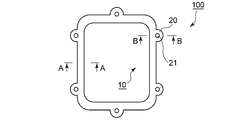
- FIG. 1 is a plan view of a gasket according to an embodiment of the present invention.
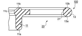
- FIG. 2 is a schematic cross-sectional view of a gasket according to Embodiment 1 of the present invention.
- FIG. 3 is a schematic cross-sectional view of the gasket according to the first embodiment of the present invention.
- FIG. 4 is a schematic cross-sectional view of a sealing structure provided with a gasket according to Embodiment 1 of the present invention.
- FIG. 5 is a schematic cross-sectional view of a gasket according to Embodiment 2 of the present invention.
- FIG. 6 is a schematic cross-sectional view of a gasket according to Embodiment 2 of the present invention.
- FIG. 1 is a plan view of a gasket according to an embodiment of the present invention.
- FIG. 2 is a schematic cross-sectional view of a gasket according to Embodiment 1 of the present invention.
- FIG. 3 is a schematic cross-sectional view of the gasket according
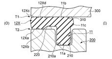
- FIG. 7 is a schematic cross-sectional view of a sealing structure provided with a gasket according to Embodiment 2 of the present invention.
- FIG. 8 is a schematic cross-sectional view of a conventional gasket.
- FIG. 9 is a schematic cross-sectional view of a sealing structure provided with a gasket according to a conventional example.
- FIG. 1 is a plan view of a gasket according to an embodiment of the present invention.
- FIG. 2 is a schematic cross-sectional view of the gasket according to the first embodiment of the present invention, and is a cross-sectional view taken along AA in FIG.
- FIG. 3 is a schematic cross-sectional view of the gasket according to the first embodiment of the present invention, and is a BB cross-sectional view in FIG.
- FIG. 4 is a schematic cross-sectional view of a sealing structure provided with a gasket according to Embodiment 1 of the present invention.
- the gasket in FIG. 4 is equivalent to the AA cross section in FIG.
- the gasket 100 is used for sealing a gap between two members fixed to each other.
- the two members are referred to as a mounted member 200 and a fixed member 300, respectively. That is, of the two members, a member to which the gasket 100 is attached is referred to as a member to be attached 200, and a member fixed to the member to be attached 200 is referred to as a member to be fixed 300.
- the attached member 200 is provided with an annular groove 210.
- the gasket 100 is in close contact with the groove bottom surface 210 a of the annular groove portion 210 and the end surface 310 of the fixed member 300.
- the clearance gap between the to-be-attached member 200 and the to-be-fixed member 300 is sealed. That is, the inside (I) of the apparatus is separated from the outside (O) of the apparatus.
- the fixed member 300 is a housing and the mounted member 200 is a cover that closes the opening of the housing
- an aluminum alloy and a magnesium alloy can be employ
- any one can also be comprised with a resin material.
- the configuration of the gasket 100 according to the present embodiment will be described in more detail.
- the gasket 100 according to the present embodiment is made of a rubber-like elastic body.
- Specific examples of the material of the gasket 100 include synthetic rubber containing at least one of nitrile rubber, styrene butadiene rubber, fluorine rubber, acrylic rubber, and silicon rubber.
- the gasket 100 includes an annular portion 10 and a plurality of attachment portions 20 provided integrally with the annular portion 10.
- the attachment portion 20 is provided so that the gasket 100 is fixed to the attached member 200 and the fixed member 300.
- the attachment portion 20 is provided with an insertion hole 21 through which a shaft portion of a bolt (not shown) for fixing the attachment member 200 and the fixation member 300 is inserted.
- the gasket 100 includes an annular gasket main body portion 11 attached to an annular groove portion 210 provided in the attached member 200 and auxiliary seal portions 12 and 13.
- the gasket body 11 is configured to be in close contact with the groove bottom surface 210 a of the annular groove 210 and the end surface 310 of the fixed member 300.
- the gasket main body 11 is provided with an attached member-side annular seal protrusion 11 a that is in close contact with the groove bottom surface 210 a of the annular groove 210, and a fixed member-side annular seal protrusion 11 b that is in close contact with the end face 310 of the fixed member 300.
- the distal end of the fixed member-side annular seal protrusion 11b is a flat surface.
- the auxiliary seal portion 12 is provided in a region excluding the region where the attachment portion 20 is provided in the gasket main body portion 11, and the auxiliary seal portion 13 is provided in the region where the attachment portion 20 is provided in the gasket main body portion 11. Is provided.
- the auxiliary seal portion 12 is configured to extend from the gasket main body portion 11 toward the anti-sealing region side (device outer side (O)) opposite to the sealing region side (device inner side (I)). And this auxiliary seal part 12 is comprised so that it may closely_contact
- the auxiliary seal portion 13 has the same configuration.
- the auxiliary seal portions 12 and 13 according to the present embodiment are configured so that the cross section has an arc shape.
- the auxiliary seal portion 12 according to the present embodiment includes the attached member-side annular convex portion 12a that is in close contact with the end surface 220 of the attached member 200 and the fixed member-side annular protrusion that is in close contact with the end surface 310 of the fixed member 300. Part 12b.
- the auxiliary seal portion 13 includes an attached member-side annular convex portion 13a that is in close contact with the end surface 220 of the attached member 200, and a fixed member-side annular convex portion 13b that is in close contact with the end surface 310 of the fixed member 300. ing.
- the inner peripheral annular convex portion that protrudes toward the sealing region side (device inner side (I)) at a position directly behind the auxiliary seal portion 12 in the gasket main body portion 11. 11c is provided.
- the auxiliary seal portions 12 and 13 extending from the gasket main body portion 11 to the anti-sealing region side (device outer side (O)) are provided. Therefore, even in an environment where corrosion by a corrosive liquid (such as a liquid containing H 2 O, NaCl, or CaCl 2 ) may occur, the sealing performance by the auxiliary seal portions 12 and 13 is impaired first.
- a corrosive liquid such as a liquid containing H 2 O, NaCl, or CaCl 2
- the corrosive liquid may adhere and stay in the vicinity shown by arrows T1 and T2.
- the to-be-attached member 200 and the to-be-fixed member 300 may corrode.
- the member to be fixed 300 is made of an aluminum alloy as in the above example, the portion of the member 300 to which the corrosive liquid is attached corrodes.
- the state in which the corrosive liquid is attached to the portion where the auxiliary seal portions 12 and 13 are in close contact with each other in the attached member 200 and the fixed member 300 is deteriorated, so that the sealing performance by the auxiliary seal portions 12 and 13 is impaired. It is. That is, when the corrosion progresses due to the corrosive liquid adhering to the portion where the auxiliary seal portions 12 and 13 are in close contact with each other, and the corroded area communicates from the apparatus external side (O) to the apparatus internal side (I), the sealing performance is impaired.
- a relatively wide space K exists between the gasket 500, the end face of the attached member 200, and the end face of the fixed member 300 (see FIG. 9). For this reason, the corrosive liquid tends to accumulate in the space K.
- the gasket 100 according to the present embodiment by providing the auxiliary seal portions 12 and 13, the space in which the corrosive liquid is accumulated can be reduced.
- the outer peripheral surfaces of the auxiliary seal portions 12 and 13 are configured to be substantially flush with the side surfaces of the attached member 200 and the fixed member 300. Thereby, there is almost no space where the corrosive liquid is accumulated (see FIG. 4).
- the corrosion progressing speed by the corrosive liquid can be suppressed even when the space in which the corrosive liquid is accumulated is small. Thereby, it is possible to delay the time required for the corrosion area on the seal surface to communicate from the outside (O) of the apparatus to the inside (I) of the apparatus. Therefore, it is possible to extend the durable life of the sealing performance of the entire gasket 100.
- an inner peripheral side annular convex portion 11 c that protrudes toward the inside (I) of the apparatus is provided at a position directly behind the auxiliary seal portion 12 in the gasket main body portion 11. Yes.
- reduction of the reaction force of the gasket main-body part 11 especially to-be-fixed member side annular seal protrusion 11b
- the fixed member 300 is made of a resin material
- the fixed member-side annular seal protrusion 11b is prevented from being deformed by the pressing force of the fixed-member-side annular seal protrusion 11b. The power cannot be so high.
- the reaction force of the fixed member side annular seal protrusion 11b is too low, the sealing performance by the fixed member side annular seal protrusion 11b becomes insufficient. Therefore, by providing the inner peripheral side annular convex portion 11c, the reaction force by the fixed member side annular seal protrusion 11b can be maintained at a force necessary for sealing performance while preventing the fixed member 300 from being deformed. .
- the fixed member-side annular seal protrusion formed on the end surface 310 side of the fixed member 300 of the gasket main body portion 11 is a flat surface whose tip is in close contact with the end surface 310. 11b is provided.
- the contact area of the fixed member-side annular seal protrusion 11b with respect to the end surface 310 of the fixed member 300 can be widened. Therefore, even if corrosion progresses in the seal portion formed by the fixed member-side annular seal protrusion 11b, it is possible to lengthen the period until the sealing performance is impaired.
- Example 2 shows a second embodiment of the present invention.
- the attached-member-side annular convex portion and the fixed-member-side annular convex portion provided in the auxiliary seal portion are one by one, whereas in the present embodiment, these are two.
- the structure provided one by one is shown. Since other configurations and operations are the same as those in the first embodiment, the same components are denoted by the same reference numerals and description thereof is omitted.
- FIG. 5 is a schematic cross-sectional view of a gasket according to Example 2 of the present invention, and corresponds to the AA cross-sectional view in FIG.
- FIG. 6 is a schematic cross-sectional view of a gasket according to Embodiment 2 of the present invention, and corresponds to the BB cross-sectional view in FIG.
- FIG. 7 is a schematic cross-sectional view of a sealing structure provided with a gasket according to Embodiment 2 of the present invention.
- the gasket in FIG. 7 is equivalent to the AA cross section in FIG.
- the sealing structure according to the present embodiment is the same as that of the first embodiment, the description thereof is omitted. Also in the gasket 100X according to the present embodiment, as in the case of the first embodiment, the annular gasket main body portion 11 attached to the annular groove portion 210 provided in the attached member 200, the auxiliary seal portions 12X and 13X, It has. Since the configuration of the gasket main body 11 is the same as that in the first embodiment, the description thereof is omitted.
- the auxiliary seal portion 12X is provided in a region excluding the region where the attachment portion 20 is provided in the gasket main body portion 11, and the auxiliary seal portion 13X is provided in the region where the attachment portion 20 is provided in the gasket main body portion 11. Is provided.
- the auxiliary seal portion 12X is configured to extend from the gasket body portion 11 toward the anti-sealing region side (device outer side (O)) opposite to the sealing region side (device inner side (I)). And this auxiliary seal part 12X is comprised so that it may respectively closely_contact
- the auxiliary seal portion 13X has the same configuration.
- auxiliary seal part 12 which concerns on a present Example is the to-be-attached member side cyclic
- a configuration is adopted in which each of the attached member-side annular convex portions and the fixed member-side annular convex portions is provided in two.
- the auxiliary seal portions 12 and 13 are each provided with two attached member side annular convex portions and two fixed member side annular convex portions. Therefore, even after the sealing performance by the attached member-side annular convex portion or the fixed member-side annular convex portion on the outside (O) side of the device is impaired, the attached member-side annular convex portion or the covered portion on the inside (I) side of the device. The sealing performance is maintained by the fixing member side annular convex portion.
- the numbers of the attached member-side annular convex portions and the fixed member-side annular convex portions are not particularly limited, and three or more can be provided. Further, it is not necessary to make the number of attached member side annular convex portions equal to the number of fixed member side annular convex portions.
- the gaskets 100 and 100X are configured to include only one annular gasket main body 11.
- the present invention is also applicable to a gasket that includes a plurality of annular gasket main body portions and that connects the gasket main body portions.
Landscapes
- Engineering & Computer Science (AREA)
- General Engineering & Computer Science (AREA)
- Mechanical Engineering (AREA)
- Gasket Seals (AREA)
Abstract
密封性の耐久寿命を延ばすことを可能とするガスケットを提供する。 互いに固定される被取付部材200と被固定部材300との間の隙間を封止するガスケット100であって、被取付部材200に設けられた環状溝部210に装着され、環状溝部210の溝底面210aと被固定部材300の端面310とにそれぞれ密着する環状のガスケット本体部11と、ガスケット本体部11から密封領域側とは反対側の反密封領域側に向かって伸びて、被取付部材200における環状溝部210よりも反密封領域側の端面220と、被固定部材300における端面310とにそれぞれ密着する補助シール部12と、を備えることを特徴とする。
Description
本発明は、互いに固定される2部材間の隙間を封止するガスケットに関する。
各種装置においては、外部から装置内部への異物や流体の侵入を防止するために、互いに固定される2部材間の隙間を封止するガスケットが広く用いられている。図8及び図9を参照して、従来例に係るガスケットについて説明する。図8は従来例に係るガスケットの模式的断面図である。図9は従来例に係るガスケットが備えられた密封構造の模式的断面図である。
ガスケット500は、互いに固定される2部材間の隙間を封止するために用いられる。説明の便宜上、2部材について、それぞれ被取付部材200,被固定部材300と称する。ガスケット500は、環状のガスケット本体部510を備えている。このガスケット本体部510の一端側と他端側にそれぞれ環状のシール突起511,512が設けられている。以上のように構成されるガスケット500においては、ガスケット本体部510が被取付部材200に設けられた環状溝部210に装着される。そして、被取付部材200と被固定部材300が固定されると、シール突起511が環状溝部210の溝底面に密着し、シール突起512が被固定部材300の端面310に密着する。これにより、被取付部材200と被固定部材300との間の隙間が封止される。つまり、装置内部側(I)と装置外部側(O)とが隔てられる。
ここで、例えば、自動車向けのガスケットにおいては、腐食液(融雪剤や海水(塩水)など)に対する密封性の耐久寿命を延ばすように求められることがある。特に、装置内部に電子部品が備えられている場合に、腐食液の浸入によるショートなどの車両の動作不具合を防ぐため、腐食液に対する密封性の耐久寿命を延ばすように求められる。例えば、上記の密封構造において、被取付部材200及び被固定部材300がアルミニウム合金やマグネシウム合金により構成されている場合に、腐食の問題が生じ得る。例えば前者の場合、図9中の矢印S1,S2の辺りに腐食液が付着して滞留し、乾燥と湿潤が繰り返されると、アルミニウムが腐食する。これは腐食液のイオン濃度差(Al3++3H2O→AL(OH)3+3H+)によるものである。このような腐食が進行し、シール面の腐食領域が装置外部側(O)から装置内部側(I)に連通してしまうことで、密封性が損なわれてしまう。
本発明の目的は、密封性の耐久寿命を延ばすことを可能とするガスケットを提供することにある。
本発明は、上記課題を解決するために以下の手段を採用した。
すなわち、本発明のガスケットは、
互いに固定される2部材間の隙間を封止するガスケットであって、
前記2部材のうちガスケットが取り付けられる被取付部材に設けられた環状溝部に装着され、該環状溝部の溝底面と前記2部材のうち前記被取付部材に固定される被固定部材の端面とにそれぞれ密着する環状のガスケット本体部と、
前記ガスケット本体部から密封領域側とは反対側の反密封領域側に向かって伸びて、前記被取付部材における前記環状溝部よりも前記反密封領域側の端面と、前記被固定部材における前記端面とにそれぞれ密着する補助シール部と、
を備えることを特徴とする。
互いに固定される2部材間の隙間を封止するガスケットであって、
前記2部材のうちガスケットが取り付けられる被取付部材に設けられた環状溝部に装着され、該環状溝部の溝底面と前記2部材のうち前記被取付部材に固定される被固定部材の端面とにそれぞれ密着する環状のガスケット本体部と、
前記ガスケット本体部から密封領域側とは反対側の反密封領域側に向かって伸びて、前記被取付部材における前記環状溝部よりも前記反密封領域側の端面と、前記被固定部材における前記端面とにそれぞれ密着する補助シール部と、
を備えることを特徴とする。
本発明によれば、ガスケット本体部から反密封領域側に伸びる補助シール部が備えられているので、腐食液による腐食が生じ得る環境下においても、最初に補助シール部による密封性が損なわれる。そして、その後に、ガスケット本体部による密封性が損なわれていくため、ガスケット全体の密封性の寿命を延ばすことが可能となる。
前記補助シール部は、
前記被取付部材における前記端面に密着する被取付部材側環状凸部と、
前記被固定部材における前記端面に密着する被固定部材側環状凸部と、
を備えるとよい。
前記被取付部材における前記端面に密着する被取付部材側環状凸部と、
前記被固定部材における前記端面に密着する被固定部材側環状凸部と、
を備えるとよい。
ここで、前記被取付部材側凸部が複数設けられていることも好適である。また、被固定部材側凸部が複数設けられていることも好適である。
前記ガスケット本体部のうち前記補助シール部の真裏の位置に、前記密封領域側に向かって突出する内周側環状凸部が設けられているとよい。
これにより、ガスケット本体部の反力の低減を抑制させることができる。
前記ガスケット本体部のうち、前記被固定部材における前記端面側には、先端が該端面に密着する平面で構成された環状シール突起が設けられていることも好適である。
これにより、前記被固定部材における前記端面に対する環状シール突起の接触領域を広くすることができる。従って、環状シール突起による密封性の寿命を延ばすことができる。
なお、上記各構成は、可能な限り組み合わせて採用し得る。
以上説明したように、本発明によれば、密封性の耐久寿命を延ばすことができる。
以下に図面を参照して、この発明を実施するための形態を、実施例に基づいて例示的に詳しく説明する。ただし、この実施例に記載されている構成部品の寸法、材質、形状、その相対配置などは、特に特定的な記載がない限りは、この発明の範囲をそれらのみに限定する趣旨のものではない。
(実施例1)
図1~図4を参照して、本発明の実施例1に係るガスケットについて説明する。図1は本発明の実施例に係るガスケットの平面図である。図2は本発明の実施例1に係るガスケットの模式的断面図であり、図1中のAA断面図である。図3は本発明の実施例1に係るガスケットの模式的断面図であり、図1中のBB断面図である。図4は本発明の実施例1に係るガスケットが備えられた密封構造の模式的断面図である。なお、図4中のガスケットは、図1中のAA断面に相当する。
図1~図4を参照して、本発明の実施例1に係るガスケットについて説明する。図1は本発明の実施例に係るガスケットの平面図である。図2は本発明の実施例1に係るガスケットの模式的断面図であり、図1中のAA断面図である。図3は本発明の実施例1に係るガスケットの模式的断面図であり、図1中のBB断面図である。図4は本発明の実施例1に係るガスケットが備えられた密封構造の模式的断面図である。なお、図4中のガスケットは、図1中のAA断面に相当する。
<密封構造>
特に、図4を参照して、本実施例に係るガスケット100が備えられた密封構造について説明する。ガスケット100は、互いに固定される2部材間の隙間を封止するために用いられる。説明の便宜上、2部材について、それぞれ被取付部材200,被固定部材300と称する。つまり、2部材のうちガスケット100が取り付けられる部材を被取付部材200と称し、この被取付部材200に固定される部材を被固定部材300と称する。被取付部材200には、環状溝部210が設けられている。ガスケット100は、この環状溝部210の溝底面210aと、被固定部材300の端面310にそれぞれ密着する。これにより、被取付部材200と被固定部材300との間の隙間が封止される。つまり、装置内部側(I)と装置外部側(O)とが隔てられる。なお、2部材の具体例として、被固定部材300がハウジングで、被取付部材200がハウジングの開口部を塞ぐカバーの場合を例に挙げることができる。なお、これら被取付部材200及び被固定部材300の材料としては、アルミニウム合金やマグネシウム合金を採用し得る。また、いずれか一方を樹脂材料で構成することもできる。
特に、図4を参照して、本実施例に係るガスケット100が備えられた密封構造について説明する。ガスケット100は、互いに固定される2部材間の隙間を封止するために用いられる。説明の便宜上、2部材について、それぞれ被取付部材200,被固定部材300と称する。つまり、2部材のうちガスケット100が取り付けられる部材を被取付部材200と称し、この被取付部材200に固定される部材を被固定部材300と称する。被取付部材200には、環状溝部210が設けられている。ガスケット100は、この環状溝部210の溝底面210aと、被固定部材300の端面310にそれぞれ密着する。これにより、被取付部材200と被固定部材300との間の隙間が封止される。つまり、装置内部側(I)と装置外部側(O)とが隔てられる。なお、2部材の具体例として、被固定部材300がハウジングで、被取付部材200がハウジングの開口部を塞ぐカバーの場合を例に挙げることができる。なお、これら被取付部材200及び被固定部材300の材料としては、アルミニウム合金やマグネシウム合金を採用し得る。また、いずれか一方を樹脂材料で構成することもできる。
<ガスケット>
本実施例に係るガスケット100の構成について、より詳細に説明する。本実施例に係るガスケット100は、ゴム状弾性体により構成される。ガスケット100の具体的な材料としては、ニトリルゴム、スチレンブタジエンゴム、フッ素ゴム、アクリルゴム、シリコンゴムのうち少なくとも1種類を含む合成ゴムを例に挙げることができる。そして、ガスケット100は、環状部10と、環状部10に対して一体的に設けられる複数の取付部20とから構成される。取付部20は、ガスケット100が被取付部材200及び被固定部材300に固定されるために設けられている。この取付部20には、被取付部材200と被固定部材300とを固定するボルト(不図示)の軸部が挿通される挿通孔21が設けられている。
本実施例に係るガスケット100の構成について、より詳細に説明する。本実施例に係るガスケット100は、ゴム状弾性体により構成される。ガスケット100の具体的な材料としては、ニトリルゴム、スチレンブタジエンゴム、フッ素ゴム、アクリルゴム、シリコンゴムのうち少なくとも1種類を含む合成ゴムを例に挙げることができる。そして、ガスケット100は、環状部10と、環状部10に対して一体的に設けられる複数の取付部20とから構成される。取付部20は、ガスケット100が被取付部材200及び被固定部材300に固定されるために設けられている。この取付部20には、被取付部材200と被固定部材300とを固定するボルト(不図示)の軸部が挿通される挿通孔21が設けられている。
そして、ガスケット100は、被取付部材200に設けられた環状溝部210に装着される環状のガスケット本体部11と、補助シール部12,13とを備えている。ガスケット本体部11は、環状溝部210の溝底面210aと被固定部材300の端面310とにそれぞれ密着するように構成されている。このガスケット本体部11には、環状溝部210の溝底面210aに密着する被取付部材側環状シール突起11aと、被固定部材300の端面310に密着する被固定部材側環状シール突起11bとが備えられている。ここで、被固定部材側環状シール突起11bの先端は平面で構成されている。
補助シール部12は、ガスケット本体部11のうち取付部20が設けられている領域を除く領域に備えられ、補助シール部13は、ガスケット本体部11のうち取付部20が設けられている領域に備えられている。補助シール部12は、ガスケット本体部11から密封領域側(装置内部側(I))とは反対側の反密封領域側(装置外部側(O))に向かって伸びるように構成されている。そして、この補助シール部12は、被取付部材200における環状溝部210よりも装置外部側(O)の端面220と、被固定部材300における端面310とにそれぞれ密着するように構成されている。補助シール部13についても、同様の構成である。
また、本実施例に係る補助シール部12,13は、断面が円弧状となるように構成されている。これにより、本実施例に係る補助シール部12は、被取付部材200における端面220に密着する被取付部材側環状凸部12aと、被固定部材300における端面310に密着する被固定部材側環状凸部12bとを備えている。補助シール部13についても同様に、被取付部材200における端面220に密着する被取付部材側環状凸部13aと、被固定部材300における端面310に密着する被固定部材側環状凸部13bとを備えている。
更に、本実施例に係るガスケット100においては、ガスケット本体部11のうち補助シール部12の真裏の位置に、密封領域側(装置内部側(I))に向かって突出する内周側環状凸部11cが設けられている。
<本実施例に係るガスケットの優れた点>
本実施例に係るガスケット100によれば、ガスケット本体部11から反密封領域側(装置外部側(O))に伸びる補助シール部12,13が備えられている。従って、腐食液(H2O、NaCl、CaCl2を含む液体など)による腐食が生じ得る環境下においても、最初に補助シール部12,13による密封性が損なわれる。例えば、図4に示すように、矢印T1,T2に示す付近に腐食液が付着して滞留し得る。これにより、被取付部材200や被固定部材300が腐食してしまうおそれがある。例えば、上記の一例のように、被固定部材300をアルミニウム合金で構成した場合には、被固定部材300において、腐食液が付着した部位が腐食してしまう。
本実施例に係るガスケット100によれば、ガスケット本体部11から反密封領域側(装置外部側(O))に伸びる補助シール部12,13が備えられている。従って、腐食液(H2O、NaCl、CaCl2を含む液体など)による腐食が生じ得る環境下においても、最初に補助シール部12,13による密封性が損なわれる。例えば、図4に示すように、矢印T1,T2に示す付近に腐食液が付着して滞留し得る。これにより、被取付部材200や被固定部材300が腐食してしまうおそれがある。例えば、上記の一例のように、被固定部材300をアルミニウム合金で構成した場合には、被固定部材300において、腐食液が付着した部位が腐食してしまう。
しかしながら、まずは、被取付部材200及び被固定部材300のうち、補助シール部12,13が密着する部位に、腐食液が付着した状態が続くことにより、補助シール部12,13による密封性が損なわれる。つまり、補助シール部12,13が密着する部位に付着した腐食液によって腐食が進行し、腐食領域が装置外部側(O)から装置内部側(I)に連通すると密封性が損なわれる。そして、これら補助シール部12,13による密封性が損なわれて、腐食液が装置内部側(I)に浸入してしまった場合に、被取付部材200及び被固定部材300のうち、ガスケット本体部11が密着する部位に腐食液が付着する。これにより、ガスケット本体部11においても、同様に、腐食液が付着した状態が続くことにより、密封性が損なわれる。このように、補助シール部12,13による密封性が損なわれた後に、ガスケット本体部11による密封性が損なわれるため、ガスケット100全体の密封性の耐久寿命を延ばすことが可能となる。なお、従来例の場合には、ガスケット500と被取付部材200の端面と被固定部材300の端面との間に、比較的広い空間Kが存在する(図9参照)。そのため、この空間Kに腐食液が溜まり易い。これに対して、本実施例に係るガスケット100においては、補助シール部12,13を設けたことにより、腐食液が溜まる空間を減らすことができる。本実施例では、補助シール部12,13の外周面が被取付部材200及び被固定部材300の側面と略同一面となるように構成されている。これにより、腐食液が溜まる空間は殆どなくなっている(図4参照)。このように、腐食液が溜まる空間が少ないことによっても、腐食液による腐食進行速度を抑制することができる。これにより、シール面における腐食領域が装置外部側(O)から装置内部側(I)に連通してしまうまでにかかる時間を遅らせることができる。従って、ガスケット100全体の密封性の耐久寿命を延ばすことを可能としている。
また、本実施例に係るガスケット100においては、ガスケット本体部11のうち補助シール部12の真裏の位置に、装置内部側(I)に向かって突出する内周側環状凸部11cが設けられている。これにより、ガスケット本体部11(特に、被固定部材側環状シール突起11b)の反力の低減を抑制させることができる。例えば、被固定部材300が樹脂材料で構成される場合には、被固定部材側環状シール突起11bの押圧力によって、被固定部材300が変形しないように、被固定部材側環状シール突起11bによる反力はあまり高くすることができない。一方で、被固定部材側環状シール突起11bの反力が低すぎると、被固定部材側環状シール突起11bによる密封性が不十分になってしまう。そこで、内周側環状凸部11cを設けることによって、被固定部材側環状シール突起11bによる反力を、被固定部材300を変形させないようにしつつ、密封性に必要な力に維持させることができる。
更に、本実施例に係るガスケット100においては、ガスケット本体部11のうち、被固定部材300における端面310側には、先端がこの端面310に密着する平面で構成された被固定部材側環状シール突起11bが設けられている。これにより、被固定部材300における端面310に対する被固定部材側環状シール突起11bの接触領域を広くすることができる。従って、被固定部材側環状シール突起11bによるシール部において、腐食が進行しても、密封性が損なわれるまでの期間を長くすることができる。
(実施例2)
図5~図7には、本発明の実施例2が示されている。上記実施例1では、補助シール部に備えられる被取付部材側環状凸部及び被固定部材側環状凸部が一つずつである構成であるのに対して、本実施例においては、これらが二つずつ備えられる構成について示す。その他の構成および作用については実施例1と同一なので、同一の構成部分については同一の符号を付して、その説明は省略する。
図5~図7には、本発明の実施例2が示されている。上記実施例1では、補助シール部に備えられる被取付部材側環状凸部及び被固定部材側環状凸部が一つずつである構成であるのに対して、本実施例においては、これらが二つずつ備えられる構成について示す。その他の構成および作用については実施例1と同一なので、同一の構成部分については同一の符号を付して、その説明は省略する。
図5は本発明の実施例2に係るガスケットの模式的断面図であり、図1中のAA断面図に相当する。図6は本発明の実施例2に係るガスケットの模式的断面図であり、図1中のBB断面図に相当する。図7は本発明の実施例2に係るガスケットが備えられた密封構造の模式的断面図である。なお、図7中のガスケットは、図1中のAA断面に相当する。
本実施例に係る密封構造については、上記実施例1の場合と同様であるので、その説明は省略する。本実施例に係るガスケット100Xにおいても、上記実施例1の場合と同様に、被取付部材200に設けられた環状溝部210に装着される環状のガスケット本体部11と、補助シール部12X,13Xとを備えている。ガスケット本体部11の構成については、上記実施例1の場合と同一であるので、その説明は省略する。
補助シール部12Xは、ガスケット本体部11のうち取付部20が設けられている領域を除く領域に備えられ、補助シール部13Xは、ガスケット本体部11のうち取付部20が設けられている領域に備えられている。補助シール部12Xは、ガスケット本体部11から密封領域側(装置内部側(I))とは反対側の反密封領域側(装置外部側(O))に向かって伸びるように構成されている。そして、この補助シール部12Xは、被取付部材200における環状溝部210よりも装置外部側(O)の端面220と、被固定部材300における端面310とにそれぞれ密着するように構成されている。補助シール部13Xについても、同様の構成である。
そして、本実施例に係る補助シール部12は、被取付部材200における端面220に密着する被取付部材側環状凸部12Xa,12Xbと、被固定部材300における端面310に密着する被固定部材側環状凸部12Xc,12Xdとを備えている。補助シール部13Xについても同様に、被取付部材200における端面220に密着する被取付部材側環状凸部13Xa,13Xbと、被固定部材300における端面310に密着する被固定部材側環状凸部13Xc,13Xdとを備えている。このように、本実施例においては、被取付部材側環状凸部及び被固定部材側環状凸部をそれぞれ二つずつ設ける構成を採用している。
以上のように構成される本実施例に係るガスケット100Xにおいても、上記実施例1の場合と同様の効果を得ることができる。また、本実施例においては、補助シール部12,13において、被取付部材側環状凸部及び被固定部材側環状凸部がそれぞれ二つずつ設けられている。従って、装置外部側(O)の被取付部材側環状凸部または被固定部材側環状凸部による密封性が損なわれた後も、装置内部側(I)の被取付部材側環状凸部または被固定部材側環状凸部によって密封性が保たれる。そして、装置内部側(I)の被取付部材側環状凸部または被固定部材側環状凸部による密封性も損なわれると、ガスケット100X全体の密封性が損なわれる。このように、密封性が損なわれるまでの期間を、より一層、延ばすことができる。
(その他)
被取付部材側環状凸部及び被固定部材側環状凸部の個数については、特に限定されるものではなく、3つ以上設けることもできる。また、被取付部材側環状凸部の個数と被固定部材側環状凸部の個数を同数にする必要もない。
被取付部材側環状凸部及び被固定部材側環状凸部の個数については、特に限定されるものではなく、3つ以上設けることもできる。また、被取付部材側環状凸部の個数と被固定部材側環状凸部の個数を同数にする必要もない。
また、上記各実施例においては、ガスケット100,100Xは、環状のガスケット本体部11を一つのみ備える構成を示した。しかしながら、本発明は、環状のガスケット本体部を複数備え、ガスケット本体部同士が連結されるガスケットにも適用可能である。
100,100X ガスケット
10 環状部
11 ガスケット本体部
11a 被取付部材側環状シール突起
11b 被固定部材側環状シール突起
11c 内周側環状凸部
12,13,12X,13X 補助シール部
12a,13a,12Xa,12Xb,13Xa,13Xb 被取付部材側環状凸部
12b,13b,12Xc,12Xd,13Xc,13Xd 被固定部材側環状凸部
20 取付部
21 挿通孔
200 被取付部材
210 環状溝部
210a 溝底面
220 端面
300 被固定部材
310 端面
10 環状部
11 ガスケット本体部
11a 被取付部材側環状シール突起
11b 被固定部材側環状シール突起
11c 内周側環状凸部
12,13,12X,13X 補助シール部
12a,13a,12Xa,12Xb,13Xa,13Xb 被取付部材側環状凸部
12b,13b,12Xc,12Xd,13Xc,13Xd 被固定部材側環状凸部
20 取付部
21 挿通孔
200 被取付部材
210 環状溝部
210a 溝底面
220 端面
300 被固定部材
310 端面
Claims (6)
- 互いに固定される2部材間の隙間を封止するガスケットであって、
前記2部材のうちガスケットが取り付けられる被取付部材に設けられた環状溝部に装着され、該環状溝部の溝底面と前記2部材のうち前記被取付部材に固定される被固定部材の端面とにそれぞれ密着する環状のガスケット本体部と、
前記ガスケット本体部から密封領域側とは反対側の反密封領域側に向かって伸びて、前記被取付部材における前記環状溝部よりも前記反密封領域側の端面と、前記被固定部材における前記端面とにそれぞれ密着する補助シール部と、
を備えることを特徴とするガスケット。 - 前記補助シール部は、
前記被取付部材における前記端面に密着する被取付部材側環状凸部と、
前記被固定部材における前記端面に密着する被固定部材側環状凸部と、
を備えることを特徴とする請求項1に記載のガスケット。 - 前記被取付部材側凸部が複数設けられていることを特徴とする請求項2に記載のガスケット。
- 前記被固定部材側凸部が複数設けられていることを特徴とする請求項2または3に記載のガスケット。
- 前記ガスケット本体部のうち前記補助シール部の真裏の位置に、前記密封領域側に向かって突出する内周側環状凸部が設けられていることを特徴とする請求項1~4のいずれか一つに記載のガスケット。
- 前記ガスケット本体部のうち、前記被固定部材における前記端面側には、先端が該端面に密着する平面で構成された環状シール突起が設けられていることを特徴とする請求項1~5のいずれか一つに記載のガスケット。
Priority Applications (4)
| Application Number | Priority Date | Filing Date | Title |
|---|---|---|---|
| US16/477,115 US11015709B2 (en) | 2017-01-18 | 2018-01-10 | Gasket and sealing structure |
| JP2018518665A JP6470473B2 (ja) | 2017-01-18 | 2018-01-10 | ガスケット及び密封構造 |
| CN201880006149.7A CN110168262B (zh) | 2017-01-18 | 2018-01-10 | 垫圈和密封构造 |
| DE112018000415.5T DE112018000415T5 (de) | 2017-01-18 | 2018-01-10 | Dichtung und Abdichtungsstruktur |
Applications Claiming Priority (2)
| Application Number | Priority Date | Filing Date | Title |
|---|---|---|---|
| JP2017006486 | 2017-01-18 | ||
| JP2017-006486 | 2017-01-18 |
Publications (1)
| Publication Number | Publication Date |
|---|---|
| WO2018135341A1 true WO2018135341A1 (ja) | 2018-07-26 |
Family
ID=62909010
Family Applications (1)
| Application Number | Title | Priority Date | Filing Date |
|---|---|---|---|
| PCT/JP2018/000238 Ceased WO2018135341A1 (ja) | 2017-01-18 | 2018-01-10 | ガスケット |
Country Status (5)
| Country | Link |
|---|---|
| US (1) | US11015709B2 (ja) |
| JP (1) | JP6470473B2 (ja) |
| CN (1) | CN110168262B (ja) |
| DE (1) | DE112018000415T5 (ja) |
| WO (1) | WO2018135341A1 (ja) |
Families Citing this family (3)
| Publication number | Priority date | Publication date | Assignee | Title |
|---|---|---|---|---|
| US20240167568A1 (en) * | 2022-11-22 | 2024-05-23 | Parker-Hannifin Corporation | Friction fit seal with flange and flange sealing bead |
| DE102023100616A1 (de) * | 2023-01-12 | 2024-07-18 | Elringklinger Ag | Baugruppe mit Dichtelement und Verwendung eines Dichtelements für eine Baugruppe und Fahrzeugkomponente und Fahrzeug |
| US12259042B2 (en) * | 2023-03-01 | 2025-03-25 | Centex Industrial Gaskey, LLC | Elastomeric sealing device |
Citations (3)
| Publication number | Priority date | Publication date | Assignee | Title |
|---|---|---|---|---|
| JPS60162245U (ja) * | 1984-04-05 | 1985-10-28 | アイシン精機株式会社 | シリンダヘツドカバ−のガスケツト |
| JPH0464661U (ja) * | 1990-10-16 | 1992-06-03 | ||
| JP2014109284A (ja) * | 2012-11-30 | 2014-06-12 | Nok Corp | ガスケット |
Family Cites Families (15)
| Publication number | Priority date | Publication date | Assignee | Title |
|---|---|---|---|---|
| US3334774A (en) * | 1964-11-27 | 1967-08-08 | Johns Manville | Fluid seal |
| JP2542038Y2 (ja) * | 1991-06-26 | 1997-07-23 | 富士重工業株式会社 | 吸気ダクト接続装置 |
| JPH06281013A (ja) * | 1993-03-25 | 1994-10-07 | Kinugawa Rubber Ind Co Ltd | シリンダヘッドカバー用ガスケット |
| EP0860602B1 (de) * | 1997-02-21 | 2001-11-21 | Dichtungstechnik G. Bruss GmbH & Co. KG | Verfahren zum Herstellen einer Zylinderkopfhaube für eine Brennkraftmaschine und Zylinderkopfhaube |
| JP4010137B2 (ja) | 2001-11-19 | 2007-11-21 | Nok株式会社 | ガスケット |
| JP4482655B2 (ja) * | 2005-04-22 | 2010-06-16 | ゴールド工業株式会社 | 精密基板収納容器のガスケット |
| JP2007239958A (ja) * | 2006-03-10 | 2007-09-20 | Nok Corp | ガスケット |
| JP4875912B2 (ja) * | 2006-03-24 | 2012-02-15 | Nok株式会社 | ガスケット |
| DE102008024265A1 (de) | 2008-05-20 | 2009-11-26 | Ibs Filtran Kunststoff-/ Metallerzeugnisse Gmbh | Dichtung für Fluid gefüllte Behälter |
| JP2012107667A (ja) * | 2010-11-16 | 2012-06-07 | Nok Corp | ガスケット |
| DE102011081973A1 (de) | 2011-09-01 | 2013-03-07 | Federal-Mogul Sealing Systems Gmbh | Profildichtung mit Randabdichtung |
| CN204592640U (zh) * | 2015-02-15 | 2015-08-26 | 岱山县奥赛密封件厂 | 排气管接口垫片 |
| CN205155139U (zh) * | 2015-11-24 | 2016-04-13 | 安徽欧耐橡塑工业有限公司 | 一种用于杯盖上的橡胶垫 |
| DE102016105047A1 (de) | 2016-03-18 | 2017-09-21 | Gea Mechanical Equipment Gmbh | Dichtungsanordnung zur Abdichtung eines Spaltes |
| US10473218B2 (en) * | 2017-10-09 | 2019-11-12 | Aptiv Technologies Limited | Perimeter seal |
-
2018
- 2018-01-10 JP JP2018518665A patent/JP6470473B2/ja active Active
- 2018-01-10 WO PCT/JP2018/000238 patent/WO2018135341A1/ja not_active Ceased
- 2018-01-10 DE DE112018000415.5T patent/DE112018000415T5/de active Pending
- 2018-01-10 CN CN201880006149.7A patent/CN110168262B/zh active Active
- 2018-01-10 US US16/477,115 patent/US11015709B2/en active Active
Patent Citations (3)
| Publication number | Priority date | Publication date | Assignee | Title |
|---|---|---|---|---|
| JPS60162245U (ja) * | 1984-04-05 | 1985-10-28 | アイシン精機株式会社 | シリンダヘツドカバ−のガスケツト |
| JPH0464661U (ja) * | 1990-10-16 | 1992-06-03 | ||
| JP2014109284A (ja) * | 2012-11-30 | 2014-06-12 | Nok Corp | ガスケット |
Also Published As
| Publication number | Publication date |
|---|---|
| JPWO2018135341A1 (ja) | 2019-01-24 |
| US20190360589A1 (en) | 2019-11-28 |
| CN110168262B (zh) | 2021-06-29 |
| DE112018000415T5 (de) | 2019-10-02 |
| JP6470473B2 (ja) | 2019-02-13 |
| US11015709B2 (en) | 2021-05-25 |
| CN110168262A (zh) | 2019-08-23 |
Similar Documents
| Publication | Publication Date | Title |
|---|---|---|
| JP6470473B2 (ja) | ガスケット及び密封構造 | |
| JP5971617B2 (ja) | ボールジョイント用ダストカバー | |
| JP5446662B2 (ja) | 密封構造 | |
| JPWO2017154615A1 (ja) | ガスケット及び密封装置 | |
| JP2011085257A (ja) | ボールジョイント用ダストカバー | |
| JP2009024834A (ja) | ボールジョイント用ダストカバー | |
| JP6167256B1 (ja) | ボールジョイント用ダストカバー及びボールジョイント用ダストカバーの取付け方法 | |
| CN108966679A (zh) | 电力转换装置 | |
| TWI793205B (zh) | 具有密封機構的裝置 | |
| JP7170938B2 (ja) | ガスケットの装着構造 | |
| CN112984110B (zh) | 用于对密封区进行密封的装置 | |
| JP5250469B2 (ja) | 密封構造及びガスケット | |
| WO2016143397A1 (ja) | 密封装置 | |
| JPH1194092A (ja) | シリンダ用シール材 | |
| JP2005322818A (ja) | 電磁波シールドケース | |
| WO2014097767A1 (ja) | ボールジョイント用ダストカバー | |
| WO2015060025A1 (ja) | ガスケット | |
| JP2020016298A (ja) | ガスケット | |
| JP2014202288A (ja) | ボールジョイント用ダストカバー | |
| JP2010139043A (ja) | オイルシール | |
| JP2007224948A (ja) | 軸付きシール | |
| JP2006038063A (ja) | シールリング | |
| WO2017149972A1 (ja) | 電力変換装置 | |
| JP2018204761A (ja) | ダストシール | |
| JPH08291868A (ja) | オイルシール |
Legal Events
| Date | Code | Title | Description |
|---|---|---|---|
| ENP | Entry into the national phase |
Ref document number: 2018518665 Country of ref document: JP Kind code of ref document: A |
|
| 121 | Ep: the epo has been informed by wipo that ep was designated in this application |
Ref document number: 18742311 Country of ref document: EP Kind code of ref document: A1 |
|
| 122 | Ep: pct application non-entry in european phase |
Ref document number: 18742311 Country of ref document: EP Kind code of ref document: A1 |