WO2018128179A1 - Matériau d'électrode négative pour batterie secondaire au lithium-ion, électrode négative pour batterie secondaire au lithium-ion et batterie secondaire au lithium-ion - Google Patents
Matériau d'électrode négative pour batterie secondaire au lithium-ion, électrode négative pour batterie secondaire au lithium-ion et batterie secondaire au lithium-ion Download PDFInfo
- Publication number
- WO2018128179A1 WO2018128179A1 PCT/JP2018/000040 JP2018000040W WO2018128179A1 WO 2018128179 A1 WO2018128179 A1 WO 2018128179A1 JP 2018000040 W JP2018000040 W JP 2018000040W WO 2018128179 A1 WO2018128179 A1 WO 2018128179A1
- Authority
- WO
- WIPO (PCT)
- Prior art keywords
- negative electrode
- lithium ion
- ion secondary
- secondary battery
- mass
- Prior art date
Links
Images
Classifications
-
- H—ELECTRICITY
- H01—ELECTRIC ELEMENTS
- H01M—PROCESSES OR MEANS, e.g. BATTERIES, FOR THE DIRECT CONVERSION OF CHEMICAL ENERGY INTO ELECTRICAL ENERGY
- H01M4/00—Electrodes
- H01M4/02—Electrodes composed of, or comprising, active material
- H01M4/36—Selection of substances as active materials, active masses, active liquids
- H01M4/58—Selection of substances as active materials, active masses, active liquids of inorganic compounds other than oxides or hydroxides, e.g. sulfides, selenides, tellurides, halogenides or LiCoFy; of polyanionic structures, e.g. phosphates, silicates or borates
- H01M4/583—Carbonaceous material, e.g. graphite-intercalation compounds or CFx
- H01M4/587—Carbonaceous material, e.g. graphite-intercalation compounds or CFx for inserting or intercalating light metals
-
- C—CHEMISTRY; METALLURGY
- C01—INORGANIC CHEMISTRY
- C01B—NON-METALLIC ELEMENTS; COMPOUNDS THEREOF; METALLOIDS OR COMPOUNDS THEREOF NOT COVERED BY SUBCLASS C01C
- C01B32/00—Carbon; Compounds thereof
- C01B32/20—Graphite
- C01B32/21—After-treatment
-
- C—CHEMISTRY; METALLURGY
- C01—INORGANIC CHEMISTRY
- C01B—NON-METALLIC ELEMENTS; COMPOUNDS THEREOF; METALLOIDS OR COMPOUNDS THEREOF NOT COVERED BY SUBCLASS C01C
- C01B32/00—Carbon; Compounds thereof
- C01B32/20—Graphite
-
- H—ELECTRICITY
- H01—ELECTRIC ELEMENTS
- H01M—PROCESSES OR MEANS, e.g. BATTERIES, FOR THE DIRECT CONVERSION OF CHEMICAL ENERGY INTO ELECTRICAL ENERGY
- H01M10/00—Secondary cells; Manufacture thereof
- H01M10/05—Accumulators with non-aqueous electrolyte
- H01M10/052—Li-accumulators
- H01M10/0525—Rocking-chair batteries, i.e. batteries with lithium insertion or intercalation in both electrodes; Lithium-ion batteries
-
- C—CHEMISTRY; METALLURGY
- C01—INORGANIC CHEMISTRY
- C01P—INDEXING SCHEME RELATING TO STRUCTURAL AND PHYSICAL ASPECTS OF SOLID INORGANIC COMPOUNDS
- C01P2002/00—Crystal-structural characteristics
- C01P2002/80—Crystal-structural characteristics defined by measured data other than those specified in group C01P2002/70
- C01P2002/82—Crystal-structural characteristics defined by measured data other than those specified in group C01P2002/70 by IR- or Raman-data
-
- C—CHEMISTRY; METALLURGY
- C01—INORGANIC CHEMISTRY
- C01P—INDEXING SCHEME RELATING TO STRUCTURAL AND PHYSICAL ASPECTS OF SOLID INORGANIC COMPOUNDS
- C01P2004/00—Particle morphology
- C01P2004/60—Particles characterised by their size
- C01P2004/61—Micrometer sized, i.e. from 1-100 micrometer
-
- C—CHEMISTRY; METALLURGY
- C01—INORGANIC CHEMISTRY
- C01P—INDEXING SCHEME RELATING TO STRUCTURAL AND PHYSICAL ASPECTS OF SOLID INORGANIC COMPOUNDS
- C01P2006/00—Physical properties of inorganic compounds
- C01P2006/40—Electric properties
-
- H—ELECTRICITY
- H01—ELECTRIC ELEMENTS
- H01M—PROCESSES OR MEANS, e.g. BATTERIES, FOR THE DIRECT CONVERSION OF CHEMICAL ENERGY INTO ELECTRICAL ENERGY
- H01M4/00—Electrodes
- H01M4/02—Electrodes composed of, or comprising, active material
- H01M2004/021—Physical characteristics, e.g. porosity, surface area
-
- H—ELECTRICITY
- H01—ELECTRIC ELEMENTS
- H01M—PROCESSES OR MEANS, e.g. BATTERIES, FOR THE DIRECT CONVERSION OF CHEMICAL ENERGY INTO ELECTRICAL ENERGY
- H01M4/00—Electrodes
- H01M4/02—Electrodes composed of, or comprising, active material
- H01M2004/026—Electrodes composed of, or comprising, active material characterised by the polarity
- H01M2004/027—Negative electrodes
-
- H—ELECTRICITY
- H01—ELECTRIC ELEMENTS
- H01M—PROCESSES OR MEANS, e.g. BATTERIES, FOR THE DIRECT CONVERSION OF CHEMICAL ENERGY INTO ELECTRICAL ENERGY
- H01M4/00—Electrodes
- H01M4/02—Electrodes composed of, or comprising, active material
- H01M4/13—Electrodes for accumulators with non-aqueous electrolyte, e.g. for lithium-accumulators; Processes of manufacture thereof
- H01M4/133—Electrodes based on carbonaceous material, e.g. graphite-intercalation compounds or CFx
-
- H—ELECTRICITY
- H01—ELECTRIC ELEMENTS
- H01M—PROCESSES OR MEANS, e.g. BATTERIES, FOR THE DIRECT CONVERSION OF CHEMICAL ENERGY INTO ELECTRICAL ENERGY
- H01M4/00—Electrodes
- H01M4/02—Electrodes composed of, or comprising, active material
- H01M4/13—Electrodes for accumulators with non-aqueous electrolyte, e.g. for lithium-accumulators; Processes of manufacture thereof
- H01M4/139—Processes of manufacture
- H01M4/1393—Processes of manufacture of electrodes based on carbonaceous material, e.g. graphite-intercalation compounds or CFx
-
- H—ELECTRICITY
- H01—ELECTRIC ELEMENTS
- H01M—PROCESSES OR MEANS, e.g. BATTERIES, FOR THE DIRECT CONVERSION OF CHEMICAL ENERGY INTO ELECTRICAL ENERGY
- H01M4/00—Electrodes
- H01M4/02—Electrodes composed of, or comprising, active material
- H01M4/62—Selection of inactive substances as ingredients for active masses, e.g. binders, fillers
- H01M4/624—Electric conductive fillers
- H01M4/625—Carbon or graphite
-
- Y—GENERAL TAGGING OF NEW TECHNOLOGICAL DEVELOPMENTS; GENERAL TAGGING OF CROSS-SECTIONAL TECHNOLOGIES SPANNING OVER SEVERAL SECTIONS OF THE IPC; TECHNICAL SUBJECTS COVERED BY FORMER USPC CROSS-REFERENCE ART COLLECTIONS [XRACs] AND DIGESTS
- Y02—TECHNOLOGIES OR APPLICATIONS FOR MITIGATION OR ADAPTATION AGAINST CLIMATE CHANGE
- Y02E—REDUCTION OF GREENHOUSE GAS [GHG] EMISSIONS, RELATED TO ENERGY GENERATION, TRANSMISSION OR DISTRIBUTION
- Y02E60/00—Enabling technologies; Technologies with a potential or indirect contribution to GHG emissions mitigation
- Y02E60/10—Energy storage using batteries
-
- Y—GENERAL TAGGING OF NEW TECHNOLOGICAL DEVELOPMENTS; GENERAL TAGGING OF CROSS-SECTIONAL TECHNOLOGIES SPANNING OVER SEVERAL SECTIONS OF THE IPC; TECHNICAL SUBJECTS COVERED BY FORMER USPC CROSS-REFERENCE ART COLLECTIONS [XRACs] AND DIGESTS
- Y02—TECHNOLOGIES OR APPLICATIONS FOR MITIGATION OR ADAPTATION AGAINST CLIMATE CHANGE
- Y02P—CLIMATE CHANGE MITIGATION TECHNOLOGIES IN THE PRODUCTION OR PROCESSING OF GOODS
- Y02P20/00—Technologies relating to chemical industry
- Y02P20/10—Process efficiency
- Y02P20/133—Renewable energy sources, e.g. sunlight
Definitions
- the present invention relates to a negative electrode material for a lithium ion secondary battery, a negative electrode for a lithium ion secondary battery, and a lithium ion secondary battery.
- a lithium ion battery (lithium ion secondary battery) is a lightweight, high energy density secondary battery, and is used as a power source for portable devices such as notebook computers and mobile phones by taking advantage of its characteristics.
- lithium ion secondary batteries are not limited to consumer applications such as portable devices, but are also being developed for use in vehicles, large-scale power storage systems for natural energy such as solar power generation and wind power generation.
- excellent input characteristics are required for lithium ion secondary batteries in order to improve the efficiency of energy use by regeneration.
- excellent long-life characteristics are also required for lithium ion secondary batteries.
- Patent Document 1 it is composed of two types of graphite particles having different optimum Raman R values (crystallinity), and one type has an average circularity obtained by a flow particle analyzer of 0.9 or more.
- a negative electrode material for a non-aqueous secondary battery that exhibits high capacity, rapid charge / discharge characteristics, and high cycle characteristics has been proposed.
- the non-aqueous secondary which shows the characteristic which was excellent in charging / discharging efficiency with low irreversible capacity
- JP 2010-251315 A Japanese Patent Laying-Open No. 2015-164143
- Patent Document 1 two types of graphite are simply mixed, and although the continuous rapid input characteristic is superior to the conventional technique, the effect on the charging characteristic with a pulse is diminished. It became clear by the examination of the person.
- Patent Document 2 two types of graphite with different particle diameters are mixed, and one type of graphite has a high aspect ratio to suppress irreversible capacity, but there is no description about charging with a pulse. It has not been done. Furthermore, it has been clarified by the present inventors that high aspect ratio graphite particles have a poor effect on charging characteristics in a pulse.
- One embodiment of the present invention has been made in view of the above-described conventional circumstances, and has a small irreversible capacity and excellent pulse charge characteristics, and a negative electrode material for a lithium ion secondary battery using the same. And it aims at providing a lithium ion secondary battery.
- ⁇ 3> The negative electrode material for lithium ion secondary batteries according to ⁇ 1> or ⁇ 2>, wherein the graphite particles have an average particle diameter of 2 ⁇ m to 30 ⁇ m.
- ⁇ 5> An amorphous carbon particle is further included, and the cumulative frequency from the low degree of circularity obtained by a flow type particle analyzer for the mixed particle of the graphite particle and the amorphous carbon particle is from 10% by number to
- ⁇ 6> The negative electrode material for a lithium ion secondary battery according to ⁇ 5>, wherein the content of the amorphous carbon particles is 1% by mass to 30% by mass.
- a current collector A negative electrode mixture layer that is disposed on the surface of the current collector and includes the negative electrode material for a lithium ion secondary battery according to any one of ⁇ 1> to ⁇ 6>; A negative electrode for a lithium ion secondary battery.
- a lithium ion secondary battery comprising the negative electrode for a lithium ion secondary battery according to ⁇ 7>.
- a negative electrode material for a lithium ion secondary battery having a small irreversible capacity and excellent pulse charge characteristics and a negative electrode for a lithium ion secondary battery and a lithium ion secondary battery using the same are provided. it can.
- the upper limit value or the lower limit value of the numerical range may be replaced with the values shown in the examples.
- the content rate and ratio of each component means the total content rate and ratio of the plurality of types of substances when there are a plurality of types of substances corresponding to each component, unless otherwise specified.
- the particle diameter of each component means a value for a mixture of the plurality of types of particles when there are a plurality of types of particles corresponding to each component, unless otherwise specified.
- the term “layer” or “film” refers to a part of the region in addition to the case where the layer or the film is formed when the region where the layer or film exists is observed. It is also included when it is formed only.
- the “solid content” of the positive electrode mixture or the negative electrode mixture means the remaining components obtained by removing volatile components such as an organic solvent from the positive electrode mixture slurry or the negative electrode mixture slurry.
- the negative electrode material for a lithium ion secondary battery according to the present disclosure has a standard deviation of the circularity (hereinafter referred to as “the circularity standard deviation”) in a range where the cumulative frequency from the low degree of circularity obtained by a flow particle analyzer ranges from 10% to 90%.
- the circularity standard deviation includes graphite particles of 0.05 to 0.1.
- the graphite particles can function as a negative electrode active material.
- the disclosed negative electrode for lithium ion secondary battery and lithium ion secondary battery can be produced.
- the standard deviation of the circularity in a specific range of the graphite particles is preferably 0.06 to 0.1, more preferably 0.06 to 0.09, and 0.06 to 0.08. Is more preferable.
- the circularity of the graphite particles can be measured using a wet flow type particle size / shape analyzer (FPIA-3000 manufactured by Malvern).
- FPIA-3000 manufactured by Malvern
- the analysis of the standard deviation of the circularity in a specific range based on the measurement result of the circularity can be performed based on the FPIA-3000 academic material (published on August 31, 2006, second edition).
- the measurement temperature is 25 ° C.
- the concentration of the measurement sample is 10% by mass
- the number of particles to be counted is 10,000.
- water is used as a solvent for dispersion.
- the graphite particles When measuring the circularity of the graphite particles, it is preferable to disperse the graphite particles in advance. For example, it is possible to disperse the graphite particles using ultrasonic dispersion, a vortex mixer or the like. In order to suppress the influence of particle collapse or particle breakage of the graphite particles, the strength and time may be appropriately adjusted in view of the strength of the graphite particles to be measured.
- ultrasonic treatment for example, an arbitrary amount of water is stored in a tank of an ultrasonic cleaner (ASU-10D, manufactured by ASONE Co., Ltd.), and then a test tube containing a dispersion liquid of graphite particles is put together with a holder. Sonication is preferably performed for 1 to 10 minutes.
- the standard deviation of the circularity in a specific range with respect to the graphite particles and the mixed particles of the graphite particles and the amorphous carbon particles is 90% by number of cumulative frequencies from the low circularity side obtained by a flow particle analyzer.
- the cumulative frequency from the low circularity side (Upper value) and the circularity (Lower value) at 10% by number can be obtained as a difference (Upper value ⁇ Lower value).
- the average circularity of the graphite particles is not particularly limited as long as the standard deviation of the circularity in a specific range is in the range of 0.05 to 0.1.
- the average circularity is 0.70 or more. It is preferable that it is 0.85 or more.
- continuous charge acceptance tends to be improved.
- the circularity when the cumulative frequency of graphite particles (the cumulative frequency from the low circularity obtained by a flow particle analyzer) is 10% by number is preferably 0.7 to 0.9.
- the graphite particles in the present disclosure are those containing graphite as a component and having a carbon network surface interlayer (d002) of less than 0.34 nm in an X-ray wide angle diffraction method.
- the carbon network surface layer (d002) has a diffraction angle 2 ⁇ of around 24 ° to 27 ° based on a diffraction profile obtained by irradiating a sample with X-rays (CuK ⁇ rays) and measuring diffraction lines with a goniometer. It can be calculated from the diffraction peak corresponding to the appearing carbon 002 plane using the Bragg equation.
- d is the length of one period
- ⁇ is the diffraction angle
- n is the reflection order
- ⁇ is the X-ray wavelength
- the graphite particles those obtained by pulverizing massive natural graphite may be used.
- the graphite particles obtained by pulverizing massive natural graphite may contain impurities, it is preferable to refine natural graphite by a purification treatment.
- the method for the purification treatment of natural graphite is not particularly limited, and can be appropriately selected from commonly used purification treatment methods. Examples thereof include flotation, electrochemical treatment, chemical treatment, and the like.
- the purity of natural graphite is preferably 99.8% or more (ash content 0.2% or less), more preferably 99.9% or more (ash content 0.1% or less) on a mass basis. When the purity is 99.8% or more, the safety of the battery is further improved, and the battery performance tends to be further improved.
- the purity of natural graphite can be calculated, for example, by measuring 100 g of graphite in an air atmosphere in an oven at 800 ° C. for 48 hours or more and then measuring the residual amount derived from ash.
- graphite particles artificial graphite obtained by firing a resin material such as an epoxy resin or a phenol resin, a pitch material obtained from petroleum, coal, or the like may be used.
- the method for obtaining artificial graphite is not particularly limited.
- raw materials such as thermoplastic resin, naphthalene, anthracene, phenanthroline, coal tar, and tar pitch are calcined in an inert atmosphere at 800 ° C. or higher.
- the method of obtaining the artificial graphite which is a baked material is mentioned.
- the obtained fired product is pulverized by a known method such as a jet mill, a vibration mill, a pin mill, a hammer mill, etc., and the average particle diameter is adjusted to about 2 ⁇ m to 40 ⁇ m to produce artificial graphite-derived graphitic particles. be able to.
- the graphite particles may be modified by a material other than graphite.
- the graphite particles may have, for example, a low crystalline carbon layer on the surface of graphite particles serving as a nucleus.
- the ratio (mass ratio) of the low crystalline carbon layer to 1 part by mass of graphite is preferably 0.005 to 10, and preferably 0.005 to 5. More preferably, it is more preferably 0.005 to 0.08. If the ratio (mass ratio) of the low crystalline carbon layer to graphite is 0.005 or more, the initial charge / discharge efficiency and the life characteristics tend to be excellent. If it is 10 or less, the output characteristics tend to be excellent.
- the content of graphite and other materials other than graphite contained in the graphite particles is, for example, TG-DTA (Thermogravimetry-Differential Thermal Analysis, It is possible to calculate the weight change ratio from 500 ° C. to 600 ° C. by measuring the weight change in the air stream by the differential heat-thermogravimetric simultaneous measurement).
- the weight change in the temperature range from 500 degreeC to 600 degreeC can be attributed to the weight change derived from materials other than graphite.
- the remainder after completion of the heat treatment can be attributed to the amount of graphite.
- the method for producing graphite particles having a low crystalline carbon layer on the surface of graphite particles serving as nuclei is not particularly limited.
- the above-described graphite particles can be efficiently produced.
- the precursor of the carbon material having lower crystallinity than the graphite particles is not particularly limited, and examples thereof include pitch and organic polymer compounds.
- pitch for example, ethylene heavy end pitch, crude oil pitch, coal tar pitch, asphalt cracking pitch, pitch produced by pyrolyzing polyvinyl chloride, etc., and naphthalene are polymerized in the presence of a super strong acid. Pitch.
- the organic polymer compound include thermoplastic resins such as polyvinyl chloride, polyvinyl alcohol, polyvinyl acetate, and polyvinyl butyral, and natural substances such as starch and cellulose.
- the temperature at which the mixture is heat-treated is not particularly limited, but is preferably 950 ° C. to 1500 ° C. from the viewpoint of improving input / output characteristics in the lithium ion secondary battery.
- the content of graphite particles serving as nuclei in the mixture before heat treatment and the precursor of the carbon material having lower crystallinity than the graphite particles are not particularly limited.
- the content of graphite particles serving as a nucleus is preferably 85% by mass to 99.9% by mass with respect to the total mass of the mixture.
- a certain Raman R value (ID / IG) is preferably 0.10 to 0.60, more preferably 0.15 to 0.55, and further preferably 0.20 to 0.50. preferable.
- the Raman spectrum can be measured using a Raman spectrometer (for example, DXR manufactured by Thermo Fisher Scientific).
- the average particle diameter of the graphite particles is preferably 2 ⁇ m to 30 ⁇ m, more preferably 2.5 ⁇ m to 25 ⁇ m, further preferably 3 ⁇ m to 20 ⁇ m, and particularly preferably 5 ⁇ m to 20 ⁇ m.
- the average particle size (d50) is determined by measuring the volume-based particle size distribution using, for example, a particle size distribution measuring apparatus using a laser light scattering method (SALD-3000, manufactured by Shimadzu Corporation), and d50 (median). It is a volume average particle diameter obtained as (diameter).
- the range of the BET specific surface area of the graphite particles is preferably 0.8 m 2 / g to 8 m 2 / g, more preferably 1 m 2 / g to 7 m 2 / g, and 1.5 m 2 / g. More preferably, it is ⁇ 6 m 2 / g. If the BET specific surface area of the graphite particles is 0.8 m 2 / g or more, excellent battery performance tends to be obtained. Further, if the BET specific surface area of the graphite particles is 8 m 2 / g or less, the tap density tends to increase, and the miscibility with other materials such as a binder and a conductive agent tends to be improved.
- the BET specific surface area can be measured from the nitrogen adsorption capacity according to JIS Z 8830: 2013.
- As the evaluation device AUTASORB-1 (trade name) manufactured by QUANTACHROME can be used.
- pretreatment a measurement cell charged with 0.05 g of a measurement sample is depressurized to 10 Pa or less with a vacuum pump, heated at 110 ° C. and held for 3 hours or more, and then kept at a normal temperature ( Cool to 25 ° C). After performing this pretreatment, the evaluation temperature is 77K, and the evaluation pressure range is measured as a relative pressure (equilibrium pressure with respect to saturated vapor pressure) of less than 1.
- the negative electrode material for a lithium ion secondary battery of the present disclosure may contain amorphous carbon particles together with the graphite particles.
- the output characteristics and energy density can be further improved while maintaining the input characteristics.
- the amorphous carbon particles are contained, the standard deviation of the circularity in a specific range obtained by the flow type particle analyzer for the mixed particles of the graphite particles and the amorphous carbon particles is 0.05 to 0.1. Preferably, it is 0.06 to 0.1, more preferably 0.07 to 0.1.
- the amorphous material occupies the negative electrode material for the lithium ion secondary battery of the present disclosure from the viewpoint of improving pulse charge characteristics and energy density.
- the proportion of carbon particles is preferably 1% by mass to 30% by mass, more preferably 2% by mass to 25% by mass, further preferably 3% by mass to 20% by mass, and more preferably 5% by mass.
- a content of ⁇ 20% by weight is particularly preferred. If the ratio of the amorphous carbon particles is 1% by mass or more, the pulse charge characteristics tend to be improved. If the ratio of the amorphous carbon particles is 30% by mass or less, it tends to be compatible with maintaining the input characteristics and overcharge resistance.
- the amorphous carbon particles in the present disclosure contain amorphous carbon as a component.
- the carbon network interlayer (d002) in the X-ray wide angle diffraction method of the amorphous carbon particles is preferably 0.340 nm to 0.390 nm, more preferably 0.341 nm to 0.385 nm, and More preferably, it is 342 nm to 0.370 nm.
- the carbon network surface layer (d002) in the X-ray wide angle diffraction method is preferably 0.340 nm to 0.360 nm, preferably 0.341 nm. More preferably, it is ⁇ 0.355 nm, and further preferably 0.342 nm to 0.350 nm.
- the amorphous carbon particles have a mass at 550 ° C. in the air stream of 70 mass% or more with respect to the mass at 25 ° C., and the mass at 650 ° C. is the mass at 25 ° C. It is preferable that it is 20 mass% or less with respect to it.
- the thermogravimetry can be measured by, for example, a TG analysis (Thermo Gravimetry Analysis) apparatus (manufactured by SII Nanotechnology Inc., TG / DTA6200). A sample of 10 mg can be collected, and measurement can be performed under a measurement condition with a temperature rising rate of 1 ° C./min using alumina as a reference under a flow of dry air of 300 mL / min.
- the amorphous carbon particles have a mass at 550 ° C. in the air stream of 90% by mass or more of the mass at 25 ° C., and the mass at 650 ° C. is 25 ° C. It is more preferable that it is 10 mass% or less of the mass in this.
- the average particle diameter (d50) of the amorphous carbon particles is preferably 1 ⁇ m to 30 ⁇ m, more preferably 2 ⁇ m to 25 ⁇ m, and even more preferably 2 ⁇ m to 23 ⁇ m. If the average particle diameter is 1 ⁇ m or more, the specific surface area can be in an appropriate range, the initial charge / discharge efficiency of the lithium ion secondary battery is excellent, the particles are in good contact with each other, and the input / output characteristics tend to be excellent. On the other hand, if the average particle diameter is 30 ⁇ m or less, unevenness on the electrode surface is unlikely to occur and the short circuit of the battery can be suppressed, and the diffusion distance of Li from the particle surface to the inside becomes relatively short, so The output characteristics tend to improve.
- the average particle diameter of the amorphous carbon particles can be measured in the same manner as in the case of the graphite particles.
- the negative electrode material for a lithium ion secondary battery of the present disclosure includes, as a negative electrode active material, a carbonaceous material other than graphite particles and amorphous carbon particles used as necessary, a metal oxide such as tin oxide and silicon oxide, Particles such as a metal composite oxide, a lithium simple substance, a lithium alloy such as a lithium aluminum alloy, or a material capable of forming an alloy with lithium such as Sn or Si may be used in combination as other particles. Other particles may be used alone or in combination of two or more.
- the metal composite oxide is not particularly limited as long as it can occlude and release lithium, and Ti (titanium), Li (lithium), or one containing both Ti and Li is preferable from the viewpoint of discharge characteristics. .
- the proportion of the other particles in the negative electrode material for the lithium ion secondary battery of the present disclosure is 0.5 mass% to It is preferably 20% by mass, more preferably 1% by mass to 15% by mass.
- a negative electrode (negative electrode) for a lithium ion secondary battery according to the present disclosure includes a current collector and a negative electrode mixture layer that is disposed on a surface of the current collector and includes the negative electrode material for a lithium ion secondary battery according to the present disclosure. Have. Details of the current collector and the negative electrode mixture layer will be described later.
- Lithium ion secondary battery If the lithium ion secondary battery of this indication is equipped with the negative electrode containing the negative electrode material for lithium ion secondary batteries of this indication, there will be no limitation in particular about the composition.
- the negative electrode material for a lithium ion secondary battery of the present disclosure may be included in the negative electrode mixture layer.
- the lithium ion secondary battery has a positive electrode, a negative electrode, a separator, and a non-aqueous electrolyte in a battery container.
- a separator is disposed between the positive electrode and the negative electrode.
- a charger is connected between the positive electrode and the negative electrode.
- lithium ions inserted in the positive electrode active material are desorbed and released into the non-aqueous electrolyte.
- the lithium ions released into the non-aqueous electrolyte move through the non-aqueous electrolyte, pass through the separator, and reach the negative electrode.
- the lithium ions that have reached the negative electrode are inserted into the negative electrode active material constituting the negative electrode.
- the lithium ion secondary battery can be charged and discharged by inserting and desorbing lithium ions between the positive electrode active material and the negative electrode active material.
- a configuration example of an actual lithium ion secondary battery will be described later (see, for example, FIG. 1).
- a positive electrode, a negative electrode, a non-aqueous electrolyte, a separator, and other components that are provided as necessary, which are components of the lithium ion secondary battery of the present disclosure, will be sequentially described.
- the lithium ion secondary battery of the present disclosure has the following positive electrode applicable to a high capacity and high input / output lithium ion secondary battery.
- the positive electrode (positive electrode plate) of the present disclosure has a current collector (positive electrode current collector) and a positive electrode mixture layer disposed on the surface thereof.
- the positive electrode mixture layer is a layer containing at least a positive electrode active material disposed on the surface of the current collector.
- the positive electrode active material preferably contains a layered lithium / nickel / manganese / cobalt composite oxide (hereinafter sometimes referred to as NMC).
- NMC has a high capacity and tends to be excellent in safety. From the viewpoint of further improving safety, it is preferable to use a mixture of NMC and spinel type lithium manganese oxide (hereinafter sometimes referred to as sp-Mn) as the positive electrode active material.
- the content of NMC is preferably 65% by mass or more, more preferably 70% by mass or more, and more preferably 80% by mass or more based on the total amount of the positive electrode mixture layer from the viewpoint of increasing the capacity of the battery. More preferably.
- composition formula (Formula 1) Li (1 + ⁇ ) Mn x Ni y Co (1-xyz) M z O 2 (Formula 1)
- (1 + ⁇ ) is the composition ratio of Li (lithium)
- x is the composition ratio of Mn (manganese)
- y is the composition ratio of Ni (nickel)
- (1-xy) z) represents the composition ratio of Co (cobalt).
- z represents the composition ratio of the element M.
- the composition ratio of O (oxygen) is 2.
- the elements M are Ti (titanium), Zr (zirconium), Nb (niobium), Mo (molybdenum), W (tungsten), Al (aluminum), Si (silicon), Ga (gallium), Ge (germanium), and Sn. It is at least one element selected from the group consisting of (tin). Further, ⁇ 0.15 ⁇ ⁇ 0.15, 0.1 ⁇ x ⁇ 0.5, 0.6 ⁇ x + y + z ⁇ 1.0, and 0 ⁇ z ⁇ 0.1.
- composition formula (Formula 2) Li (1 + ⁇ ) Mn (2- ⁇ ) M ′ ⁇ O 4 (Chemical formula 2)
- (1 + ⁇ ) represents the composition ratio of Li
- (2- ⁇ ) represents the composition ratio of Mn
- ⁇ represents the composition ratio of the element M ′.
- the composition ratio of O (oxygen) is 4.
- the element M ′ is preferably at least one element selected from the group consisting of Mg (magnesium), Ca (calcium), Sr (strontium), Al, Ga, Zn (zinc), and Cu (copper). . 0 ⁇ ⁇ ⁇ 0.2 and 0 ⁇ ⁇ ⁇ 0.1.
- Mg or Al is preferably used as the element M ′ in the composition formula (Chemical Formula 2).
- the battery life tends to be extended.
- battery safety tends to be improved.
- the elution of Mn can be reduced by adding the element M ′, the storage characteristics and the charge / discharge cycle characteristics tend to be improved.
- the positive electrode active material materials other than NMC and sp-Mn may be used.
- positive electrode active materials other than NMC and sp-Mn those commonly used in this field can be used, and lithium-containing composite metal oxides other than NMC and sp-Mn, olivine type lithium salts, chalcogen compounds, manganese dioxide, etc.
- the lithium-containing composite metal oxide is a metal oxide containing lithium and a transition metal or a metal oxide in which a part of the transition metal in the metal oxide is substituted with a different element.
- the different elements include Na, Mg, Sc, Y, Mn, Fe, Co, Ni, Cu, Zn, Al, Cr, Pb, Sb, V, and B.
- lithium-containing composite metal oxides other than NMC and sp-Mn include Li x CoO 2 , Li x NiO 2 , Li x MnO 2 , Li x Co y Ni 1-y O 2 , and Li x Co y M 1 1-.
- y O z (in Li x Co y M 1 1-y O z , M 1 is Na, Mg, Sc, Y, Mn, Fe, Ni, Cu, Zn, Al, Cr, Pb, Sb, V, and B) Represents at least one element selected from the group consisting of: Li x Ni 1-y M 2 y O z (wherein M 2 is Na, Mg, Sc, Y in Li x Ni 1-y M 2 y O z). Mn, Fe, Co, Cu, Zn, Al, Cr, Pb, Sb, at least one element selected from the group consisting of V and B.) and the like.
- x is in the range of 0 ⁇ x ⁇ 1.2
- y is in the range of 0 to 0.9
- z is in the range of 2.0 to 2.3.
- the x value indicating the molar ratio of lithium increases or decreases due to charge / discharge.
- the olivine type lithium salt include LiFePO 4 .
- the chalcogen compound include titanium disulfide and molybdenum disulfide.
- a positive electrode active material may be used individually by 1 type, and may be used in combination of 2 or more type.
- the positive electrode mixture layer contains a positive electrode active material, a binder, and the like, and is disposed on the current collector.
- a positive electrode active material a binder, and the like
- a positive electrode active material, a binder, and other materials such as a conductive agent and a thickener that are used as needed are mixed in a dry form to form a sheet, which is then pressure-bonded to a current collector (dry method).
- a mixture layer can be formed.
- a positive electrode active material, a binder, and other materials such as a conductive agent and a thickener used as necessary are dissolved or dispersed in a dispersion solvent to form a positive electrode mixture slurry, which is applied to a current collector. Then, the positive electrode mixture layer can be formed by drying (wet method). As described above, it is preferable to use a layered lithium / nickel / manganese / cobalt composite oxide (NMC) as the positive electrode active material.
- NMC layered lithium / nickel / manganese / cobalt composite oxide
- the positive electrode active material is used in powder form (granular form) and mixed.
- particles of the positive electrode active material such as NMC and sp-Mn
- particles having a shape such as a lump shape, a polyhedron shape, a spherical shape, an elliptical spherical shape, a plate shape, a needle shape, and a column shape can be used.
- the average particle size (d50) of the positive electrode active material particles such as NMC and sp-Mn (when the primary particles are aggregated to form secondary particles, the average particle size (d50) of the secondary particles) is: From the viewpoint of tap density (fillability) and miscibility with other materials during electrode formation, it is preferably 1 ⁇ m to 30 ⁇ m, more preferably 3 ⁇ m to 25 ⁇ m, and preferably 5 ⁇ m to 15 ⁇ m. Further preferred.
- the average particle diameter (d50) of the positive electrode active material particles can be measured in the same manner as in the case of the graphite particles.
- positive electrode active range of BET specific surface area of the particles of a substance such as sp-Mn is preferably 0.2m 2 /g ⁇ 4.0m 2 / g, 0.3m 2 /g ⁇ 2.5m 2 more preferably / a g, more preferably from 0.4m 2 /g ⁇ 1.5m 2 / g. If the BET specific surface area of the positive electrode active material particles is 0.2 m 2 / g or more, excellent battery performance tends to be obtained. Further, when the BET specific surface area of the positive electrode active material particles is 4.0 m 2 / g or less, the tap density tends to increase, and the miscibility with other materials such as a binder and a conductive agent tends to improve. is there.
- the BET specific surface area can be measured in the same manner as in the case of graphite particles.
- the conductive agent for the positive electrode examples include metal materials such as copper and nickel; graphite such as natural graphite and artificial graphite (graphite); carbon black such as acetylene black; and carbonaceous materials such as amorphous carbon such as needle coke. It is done.
- the electrically conductive agent for positive electrodes may be used individually by 1 type, and may be used in combination of 2 or more type.
- the content of the conductive agent with respect to the mass of the positive electrode mixture layer is preferably 0.01% by mass to 50% by mass, more preferably 0.1% by mass to 30% by mass, and 1% by mass to 15%. More preferably, it is mass%. When the content of the conductive agent is 0.01% by mass or more, sufficient conductivity tends to be easily obtained. If the content rate of a electrically conductive agent is 50 mass% or less, it exists in the tendency which can suppress the fall of battery capacity.
- the binder for the positive electrode is not particularly limited, and when the positive electrode mixture layer is formed by a wet method, a material having good solubility or dispersibility in the dispersion solvent is selected.
- resin-based polymers such as polyethylene, polypropylene, polyethylene terephthalate, polyimide, and cellulose
- rubbery polymers such as SBR (styrene-butadiene rubber) and NBR (acrylonitrile-butadiene rubber)
- PVdF polyvinylidene fluoride Fluorine-based polymers such as polytetrafluoroethylene, polytetrafluoroethylene-vinylidene fluoride copolymer, and fluorinated polyvinylidene fluoride
- the binder for positive electrodes may be used individually by 1 type, and may be used in combination of 2 or more type. From the viewpoint of the stability of the positive electrode, it is preferable to use a fluorine-based polymer such as polyvinylidene fluoride (PVdF) or polytetrafluoroethylene-vinylidene fluoride copolymer as the binder.
- PVdF polyvinylidene fluoride
- the content of the binder with respect to the mass of the positive electrode mixture layer is preferably 0.1% by mass to 60% by mass, more preferably 1% by mass to 40% by mass, and 3% by mass to 10% by mass. % Is more preferable.
- the binder content is 0.1% by mass or more, the positive electrode active material can be sufficiently bound, sufficient mechanical strength of the positive electrode mixture layer is obtained, and battery performance such as cycle characteristics is improved. There is a tendency.
- the content of the binder is 60% by mass or less, sufficient battery capacity and conductivity tend to be obtained.
- the thickener is effective for adjusting the viscosity of the slurry.
- the thickener is not particularly limited, and specific examples include carboxymethyl cellulose, methyl cellulose, hydroxymethyl cellulose, ethyl cellulose, polyvinyl alcohol, oxidized starch, phosphorylated starch, casein, and salts thereof.
- a thickener may be used individually by 1 type, and may be used in combination of 2 or more type.
- the content of the thickener with respect to the mass of the positive electrode mixture layer is preferably 0.1% by mass to 20% by mass from the viewpoint of input / output characteristics and battery capacity. More preferably, the content is from 15% by mass to 15% by mass, and further preferably from 1% by mass to 10% by mass.
- any type of solvent can be used as long as it can dissolve or disperse the positive electrode active material, the binder, and the conductive agent or thickener used as necessary.
- an aqueous solvent or an organic solvent may be used.
- aqueous solvent examples include water, alcohol and a mixed solvent of water and alcohol
- examples of the organic solvent include N-methyl-2-pyrrolidone (NMP), dimethylformamide, dimethylacetamide, methyl ethyl ketone
- examples include cyclohexanone, methyl acetate, methyl acrylate, tetrahydrofuran (THF), toluene, acetone, diethyl ether, dimethyl sulfoxide, benzene, xylene, hexane, and the like.
- NMP N-methyl-2-pyrrolidone
- dimethylformamide dimethylacetamide
- methyl ethyl ketone examples include cyclohexanone, methyl acetate, methyl acrylate, tetrahydrofuran (THF), toluene, acetone, diethyl ether, dimethyl sulfoxide, benzene, xylene, hexane
- the positive electrode mixture layer formed on the current collector using a wet method or a dry method is preferably consolidated by a hand press or a roller press.
- the density of the consolidated positive electrode mixture layer is preferably in the range of 2.5 g / cm 3 to 3.5 g / cm 3 from the viewpoint of further improving input / output characteristics and safety, and is preferably 2.55 g / cm 3 . more preferably 3 to a range of 3.15 g / cm 3, more preferably in the range of 2.6g / cm 3 ⁇ 3.0g / cm 3.
- the amount of the cathode mixture slurry applied to the current collector when forming the cathode mixture layer is 30 g / m 2 to 30 g / m 2 as the solid content of the cathode mixture from the viewpoint of energy density and input / output characteristics. It is preferably 170 g / m 2 , more preferably 40 g / m 2 to 160 g / m 2 , and still more preferably 40 g / m 2 to 150 g / m 2 .
- the average thickness of the positive electrode mixture layer is preferably 19 ⁇ m to 68 ⁇ m, and more preferably 23 ⁇ m to 64 ⁇ m. More preferably, it is 36 ⁇ m to 60 ⁇ m. In the present disclosure, the average thickness of the mixture layer is the average value of the thicknesses at any 10 locations.
- the material processed into various shapes can be used.
- the metal material include a metal foil, a metal plate, a metal thin film, and an expanded metal. Among these, it is preferable to use a metal thin film. In addition, you may form a thin film suitably in mesh shape.
- the average thickness of the current collector is not particularly limited, and is preferably 1 ⁇ m to 1 mm, and preferably 3 ⁇ m to 100 ⁇ m, from the viewpoint of obtaining strength required for the current collector and good flexibility. More preferably, it is 5 ⁇ m to 100 ⁇ m.
- the lithium ion secondary battery of the present disclosure has the following negative electrode applicable to a high capacity and high input / output lithium ion secondary battery.
- the negative electrode (negative electrode plate) of the present disclosure has a current collector (negative electrode current collector) and a negative electrode mixture layer disposed on the surface thereof.
- the negative electrode mixture layer is a layer containing at least a negative electrode active material disposed on the surface of the current collector.
- the negative electrode for a lithium ion secondary battery of the present disclosure can be used.
- the negative electrode active material included in the negative electrode mixture layer according to the lithium ion secondary battery of the present disclosure the negative electrode material for a lithium ion secondary battery of the present disclosure is used.
- the content of the negative electrode material for a lithium ion secondary battery of the present disclosure is preferably 80% by mass or more, and 85% by mass or more with respect to the total amount of the negative electrode mixture layer, from the viewpoint of increasing the capacity of the battery. Is more preferable, and it is still more preferable that it is 90 mass% or more.
- the negative electrode mixture layer contains a negative electrode active material, a binder, and the like, and is disposed on the current collector.
- a negative electrode active material a binder, and the like
- a negative electrode active material, a binder, and other materials such as a conductive agent and a thickener used as required are dissolved or dispersed in a dispersion solvent to form a slurry of a negative electrode mixture, which is applied to a current collector,
- a negative electrode mixture layer can be formed by drying (wet method).
- Examples of the conductive agent for the negative electrode include natural graphite other than the graphite particles according to the negative electrode material for lithium ion secondary batteries of the present disclosure, graphite such as artificial graphite, carbon black such as acetylene black, needle coke, and the like. Regular carbon or the like can be used.
- As the conductive agent for the negative electrode one kind may be used alone, or two or more kinds may be used in combination. Thus, there exists a tendency which produces effects, such as reducing the resistance of an electrode, by adding a electrically conductive agent.
- the content of the conductive agent relative to the mass of the negative electrode mixture layer is preferably 1% by mass to 45% by mass from the viewpoint of improving conductivity and reducing the initial irreversible capacity, and is 2% by mass to 42% by mass. More preferably, the content is 3% by mass to 40% by mass.
- the content of the conductive agent is 1% by mass or more, sufficient conductivity tends to be easily obtained. If the content rate of a electrically conductive agent is 45 mass% or less, it exists in the tendency which can suppress the fall of battery capacity.
- the binder for the negative electrode is not particularly limited as long as it is a material that is stable with respect to the non-aqueous electrolyte or the dispersion solvent used in forming the electrode.
- resin-based polymers such as polyethylene, polypropylene, polyethylene terephthalate, cellulose, and nitrocellulose; rubbery polymers such as SBR (styrene-butadiene rubber) and NBR (acrylonitrile-butadiene rubber); polyvinylidene fluoride (PVdF) ), Fluorine-based polymers such as polytetrafluoroethylene and fluorinated polyvinylidene fluoride; polymer compositions having ion conductivity of alkali metal ions (particularly lithium ions), and the like.
- the binder for negative electrodes may be used individually by 1 type, and may be used in combination of 2 or more type.
- a fluorine-based polymer typified by SBR or polyvinylidene fluoride.
- the content of the binder with respect to the mass of the negative electrode mixture layer is preferably 0.1% by mass to 20% by mass, more preferably 0.5% by mass to 15% by mass, and 0.6% by mass. More preferably, the content is from 10% to 10% by mass.
- the content of the binder is 0.1% by mass or more, the negative electrode active material can be sufficiently bound, and sufficient mechanical strength of the negative electrode mixture layer tends to be obtained.
- the content of the binder is 20% by mass or less, sufficient battery capacity and conductivity tend to be obtained.
- the content of the binder with respect to the mass of the negative electrode mixture layer when a fluorine-based polymer typified by polyvinylidene fluoride is used as the main component as the binder is 1% by mass to 15% by mass. It is preferably 2% by mass to 10% by mass, more preferably 3% by mass to 8% by mass.
- Thickener is used to adjust the viscosity of the slurry.
- the thickener is not particularly limited, and specific examples include carboxymethyl cellulose, methyl cellulose, hydroxymethyl cellulose, ethyl cellulose, polyvinyl alcohol, oxidized starch, phosphorylated starch, casein, and salts thereof.
- a thickener may be used individually by 1 type, and may be used in combination of 2 or more type.
- the content of the thickener with respect to the mass of the negative electrode mixture layer is preferably 0.1% by mass to 5% by mass from the viewpoint of input / output characteristics and battery capacity. It is more preferably from 3% by mass to 3% by mass, and further preferably from 0.6% by mass to 2% by mass.
- any kind of solvent can be used as long as it can dissolve or disperse the negative electrode active material, the binder, and the conductive agent or thickener used as necessary.
- an aqueous solvent or an organic solvent may be used.
- the aqueous solvent include water, alcohol, and a mixed solvent of water and alcohol.
- organic solvents examples include N-methyl-2-pyrrolidone (NMP), dimethylformamide, dimethylacetamide, methyl ethyl ketone, cyclohexanone, methyl acetate, methyl acrylate, tetrahydrofuran (THF), toluene, acetone, diethyl ether, dimethyl sulfoxide , Benzene, xylene, hexane and the like.
- NMP N-methyl-2-pyrrolidone
- dimethylformamide dimethylacetamide
- methyl ethyl ketone cyclohexanone
- methyl acetate methyl acrylate
- THF tetrahydrofuran
- toluene acetone
- diethyl ether dimethyl sulfoxide
- Benzene xylene, hexane and the like.
- a thickener it is preferable to use a thickener.
- the density of the negative electrode mixture layer is preferably 0.7 g / cm 3 to 2 g / cm 3 , more preferably 0.8 g / cm 3 to 1.9 g / cm 3 , and 0.9 g / cm 3. More preferably, it is 3 to 1.8 g / cm 3 .
- the density of the negative electrode mixture layer is 0.7 g / cm 3 or more, the conductivity between the negative electrode active materials is improved, an increase in battery resistance can be suppressed, and the capacity per unit volume tends to be improved. .
- the density of the negative electrode mixture layer is 2 g / cm 3 or less, the discharge characteristics are deteriorated due to an increase in the initial irreversible capacity and a decrease in the permeability of the non-aqueous electrolyte near the interface between the current collector and the negative electrode active material. There is a tendency to be less likely to invite.
- the amount of the negative electrode mixture slurry applied to the current collector when forming the negative electrode mixture layer is 30 g / m 2 to 30 g / m 2 as the solid content of the negative electrode mixture from the viewpoint of energy density and input / output characteristics.
- the average thickness of the negative electrode mixture layer is preferably 10 ⁇ m to 150 ⁇ m, and more preferably 15 ⁇ m to 140 ⁇ m. More preferably, it is 15 ⁇ m to 120 ⁇ m.
- the material of the current collector for the negative electrode is not particularly limited, and specific examples include metal materials such as copper, nickel, stainless steel, and nickel-plated steel. Among these, copper is preferable from the viewpoint of ease of processing and cost.
- the material processed into various shapes can be used. Specific examples include metal foil, metal plate, metal thin film, expanded metal, and the like. Among these, a metal thin film is preferable, and a copper foil is more preferable. Copper foil includes a rolled copper foil formed by a rolling method and an electrolytic copper foil formed by an electrolytic method, both of which are suitable as a current collector.
- the average thickness of the current collector is not particularly limited. For example, it is preferably 5 ⁇ m to 50 ⁇ m, more preferably 8 ⁇ m to 40 ⁇ m, and even more preferably 9 ⁇ m to 30 ⁇ m. When the average thickness of the current collector is less than 25 ⁇ m, the strength can be improved by using a stronger copper alloy (phosphor bronze, titanium copper, Corson alloy, Cu—Cr—Zr alloy, etc.) than pure copper. .
- the nonaqueous electrolytic solution generally contains a nonaqueous solvent and a lithium salt (electrolyte).
- the nonaqueous solvent include cyclic carbonates, chain carbonates, and cyclic sulfonate esters.
- the cyclic carbonate an alkylene group constituting the cyclic carbonate preferably has 2 to 6 carbon atoms, and more preferably 2 to 4 carbon atoms. Examples include ethylene carbonate, propylene carbonate, butylene carbonate. Of these, ethylene carbonate and propylene carbonate are preferable.
- the chain carbonate is preferably a dialkyl carbonate, and the two alkyl groups each preferably have 1 to 5 carbon atoms, more preferably 1 to 4 carbon atoms.
- Examples include symmetric chain carbonates such as dimethyl carbonate, diethyl carbonate, and di-n-propyl carbonate; and asymmetric chain carbonates such as ethyl methyl carbonate, methyl-n-propyl carbonate, and ethyl-n-propyl carbonate. Of these, dimethyl carbonate and ethyl methyl carbonate are preferred. Since dimethyl carbonate has better oxidation resistance and reduction resistance than diethyl carbonate, it tends to improve cycle characteristics.
- ethyl methyl carbonate Since ethyl methyl carbonate has an asymmetric molecular structure and a low melting point, it tends to improve low-temperature characteristics.
- a mixed solvent in which ethylene carbonate, dimethyl carbonate and ethyl methyl carbonate are combined is particularly preferable because battery characteristics can be secured in a wide temperature range.
- the content of the cyclic carbonate and the chain carbonate is preferably 85% by mass or more, more preferably 90% by mass or more, and 95% by mass or more based on the total amount of the nonaqueous solvent. More preferably.
- the mixing ratio of the cyclic carbonate and the chain carbonate is such that the cyclic carbonate / chain carbonate (volume ratio) is 1/9 to 6/4 from the viewpoint of battery characteristics. It is preferably 2/8 to 5/5.
- cyclic sulfonate esters include 1,3-propane sultone, 1-methyl-1,3-propane sultone, 3-methyl-1,3-propane sultone, 1,4-butane sultone, 1,3-propene sultone, 1 , 4-butene sultone and the like.
- the non-aqueous electrolyte may further contain a chain ester, a cyclic ether, a chain ether, a cyclic sulfone and the like.
- chain esters include methyl acetate, ethyl acetate, propyl acetate, and methyl propionate.
- the cyclic ether include tetrahydrofuran, 2-methyltetrahydrofuran, tetrahydropyran and the like.
- chain ethers include dimethoxyethane and dimethoxymethane.
- the cyclic sulfone include sulfolane and 3-methylsulfolane.
- the nonaqueous electrolytic solution may contain a phosphoric acid silyl ester compound.
- phosphoric acid silyl ester compounds include tris (trimethylsilyl) phosphate, dimethyltrimethylsilyl phosphate, methylbis (trimethylsilyl) phosphate, diethyltrimethylsilyl phosphate, ethylbis (trimethylsilyl) phosphate, dipropyltrimethylsilyl phosphate, phosphoric acid Propylbis (trimethylsilyl), dibutyltrimethylsilyl phosphate, butylbis (trimethylsilyl) phosphate, dioctyltrimethylsilyl phosphate, octylbis (trimethylsilyl) phosphate, diphenyltrimethylsilyl phosphate, phenylbis (trimethylsilyl) phosphate, di (trifluoroethyl phosphate) ) (Trimethylsilyl), trifluoroethylbis
- Tris (trimethylsilyl) phosphate can suppress an increase in resistance with a smaller addition amount than other silyl phosphate compounds.
- These silyl phosphate esters may be used alone or in combination of two or more.
- the content of the silyl phosphate compound is preferably 0.1% by mass to 5% by mass with respect to the total amount of the non-aqueous electrolyte. It is more preferably 3% by mass to 3% by mass, and further preferably 0.4% by mass to 2% by mass.
- the content of tris (trimethylsilyl) phosphate (TMSP) is 0.1% by mass to the total amount of the nonaqueous electrolytic solution. It is preferably 0.5% by mass, more preferably 0.1% by mass to 0.4% by mass, and still more preferably 0.2% by mass to 0.4% by mass.
- the content rate of TMSP is in the above range, the life characteristics tend to be improved by the action of thin SEI (Solid Electrolyte Interface).
- the nonaqueous electrolytic solution may contain vinylene carbonate (VC).
- VC vinylene carbonate
- the content of vinylene carbonate is preferably 0.3% by mass to 1.6% by mass, more preferably 0.3% by mass to 1.5% by mass with respect to the total amount of the non-aqueous electrolyte. More preferably, the content is 0.3% by mass to 1.3% by mass.
- the life characteristics can be improved, and the effect of reducing the charge / discharge efficiency due to excessive VC being decomposed during charge / discharge of the lithium ion secondary battery can be prevented. It tends to be possible.
- the lithium salt is not particularly limited as long as it is a lithium salt that can be used as an electrolyte of a non-aqueous electrolyte for a lithium ion secondary battery, and includes the following inorganic lithium salts, fluorine-containing organic lithium salts, oxalate borate salts, etc. Is mentioned.
- inorganic lithium salt LiPF 6, LiBF 4, LiAsF 6, LiSbF 6 inorganic fluoride salts, such as, LiClO 4, Libro 4, perhalogenate of LiIO 4, etc., and the like inorganic chloride salts such as LiAlCl 4 It is done.
- fluorine-containing organic lithium salt examples include perfluoroalkane sulfonates such as LiCF 3 SO 3 ; LiN (CF 3 SO 2 ) 2 , LiN (CF 3 CF 2 SO 2 ) 2 , LiN (CF 3 SO 2 ) (C Perfluoroalkanesulfonylimide salts such as 4 F 9 SO 2 ); perfluoroalkanesulfonylmethide salts such as LiC (CF 3 SO 2 ) 3 ; Li [PF 5 (CF 2 CF 2 CF 3 )], Li [PF 4 (CF 2 CF 2 CF 3 ) 2 ], Li [PF 3 (CF 2 CF 2 CF 3 ) 3 ], Li [PF 5 (CF 2 CF 2 CF 2 CF 3 )], Li [PF 4 (CF 2 CF 2 CF 3 ) 2 ], Li [PF 3 (CF 2 CF 2 CF 3 ) 2 ], Li [PF 3 (CF 2 CF 2 CF 3 ) 2 ], Li [
- oxalatoborate salt examples include lithium bis (oxalato) borate and lithium difluorooxalatoborate. These lithium salts may be used individually by 1 type, and may be used in combination of 2 or more type. Among these, lithium hexafluorophosphate (LiPF 6 ) is preferable in terms of solubility in a solvent, charge / discharge characteristics, output characteristics, cycle characteristics, and the like when a lithium ion secondary battery is used.
- LiPF 6 lithium hexafluorophosphate
- concentration of the electrolyte in the non-aqueous electrolyte there is no particular restriction on the concentration of the electrolyte in the non-aqueous electrolyte.
- concentration range of the electrolyte is as follows.
- the lower limit of the concentration is 0.5 mol / L or more, preferably 0.6 mol / L or more, more preferably 0.7 mol / L or more.
- the upper limit of the concentration is 2 mol / L or less, preferably 1.8 mol / L or less, more preferably 1.7 mol / L or less. If the concentration of the electrolyte is 0.5 mol / L or more, the electric conductivity of the nonaqueous electrolytic solution tends to be sufficient.
- the concentration of the electrolyte is 2 mol / L or less, an increase in the viscosity of the nonaqueous electrolytic solution is suppressed, so that the electrical conductivity tends to increase.
- the electrical conductivity of the non-aqueous electrolyte increases, the performance of the lithium ion secondary battery tends to be improved.
- the separator is not particularly limited as long as it has ion permeability while electronically insulating between the positive electrode and the negative electrode, and has resistance to oxidation on the positive electrode side and reducibility on the negative electrode side.
- a material (material) of the separator that satisfies such characteristics, a resin, an inorganic substance, or the like is used.
- the resin an olefin polymer, a fluorine polymer, a cellulose polymer, polyimide, nylon, or the like is used.
- a porous sheet or a nonwoven fabric made of a polyolefin such as polyethylene or polypropylene.
- oxides such as alumina and silicon dioxide, nitrides such as aluminum nitride and silicon nitride, glass, and the like are used.
- the said inorganic substance of fiber shape or particle shape made into the nonwoven fabric, the thing made into the woven fabric, or the thin film-shaped base materials, such as a microporous film can be used as a separator.
- a substrate having a pore diameter of 0.01 ⁇ m to 1 ⁇ m and an average thickness of 5 ⁇ m to 50 ⁇ m is preferably used.
- the composite porous layer using binders, such as resin can also be used as a separator.
- this composite porous layer may be formed on the surface of another separator to form a multilayer separator.
- this composite porous layer may be formed on the surface of the positive electrode or the negative electrode to form a separator.
- a cleavage valve may be provided as another component of the lithium ion secondary battery. By opening the cleavage valve, it is possible to suppress an increase in pressure inside the battery and to improve safety. Moreover, you may provide the structural member which discharge
- an inert gas for example, carbon dioxide
- As a material used for the said structural member lithium carbonate, polyethylene carbonate, polypropylene carbonate, etc. are preferable.
- the negative electrode capacity of the lithium ion secondary battery refers to [negative electrode discharge capacity].
- the positive electrode capacity of the lithium ion secondary battery indicates [initial charge capacity of the positive electrode ⁇ irreversible capacity of the negative electrode or the positive electrode, whichever is greater].
- the “negative electrode discharge capacity” is defined to be calculated by the charge / discharge device when the lithium ions inserted into the negative electrode active material are desorbed.
- the “initial charge capacity of the positive electrode” is defined as that calculated by the charge / discharge device when lithium ions are desorbed from the positive electrode active material.
- the capacity ratio between the negative electrode and the positive electrode can be calculated from, for example, “negative electrode discharge capacity / lithium ion secondary battery discharge capacity”.
- the discharge capacity of the lithium ion secondary battery is, for example, 4.2 V, 0.1 C to 0.5 C, 0.1 C after performing constant current constant voltage (CCCV) charging with an end time of 2 hours to 5 hours. It can be measured under conditions when a constant current (CC) discharge is performed up to 2.7 V at ⁇ 0.5 C.
- CCCV constant current constant voltage
- For the discharge capacity of the negative electrode a negative electrode whose discharge capacity was measured for a lithium ion secondary battery was cut into a predetermined area, lithium metal was used as a counter electrode, and a single electrode cell was produced via a separator impregnated with a non-aqueous electrolyte.
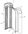
- FIG. 1 is a cross-sectional view of a lithium ion secondary battery to which the present disclosure is applied.
- a lithium ion secondary battery 1 of the present disclosure has a bottomed cylindrical battery container 6 made of nickel-plated steel.
- the battery container 6 accommodates an electrode winding group 5 in which a strip-like positive electrode plate 2 and a negative electrode plate 3 are wound in a spiral shape through a separator 4 made of a polyethylene porous sheet.
- the separator 4 has a width of 58 mm and an average thickness of 30 ⁇ m.
- a ribbon-like positive electrode tab terminal made of aluminum and having one end fixed to the positive electrode plate 2 is led out.
- the other end of the positive electrode tab terminal is joined by ultrasonic welding to the lower surface of a disk-shaped battery lid that is disposed on the upper side of the electrode winding group 5 and serves as a positive electrode external terminal.
- a negative electrode tab terminal made of copper and having one end fixed to the negative electrode plate 3 is led to the lower end surface of the electrode winding group 5.
- the other end of the negative electrode tab terminal is joined to the inner bottom of the battery container 6 by resistance welding. Therefore, the positive electrode tab terminal and the negative electrode tab terminal are led out to the opposite sides of the both end surfaces of the electrode winding group 5, respectively.
- FIG. 1 The battery lid is caulked and fixed to the upper part of the battery container 6 via an insulating resin gasket. For this reason, the inside of the lithium ion secondary battery 1 is sealed. In addition, a non-aqueous electrolyte (not shown) is injected into the battery container 6.
- Example 1 [Production of positive electrode plate]
- NMP N-methyl-2-pyrrolidone
- This slurry was applied substantially uniformly and uniformly on both surfaces of an aluminum foil having an average thickness of 20 ⁇ m, which is a positive electrode current collector. Then, the drying process was performed and it consolidated by the press to the density of 2.7 g / cm ⁇ 3 >.
- the single-sided coating amount of the positive electrode mixture slurry was 40 g / m 2 as the solid content of the positive electrode mixture.
- a mixture was obtained by mixing 100 parts by mass of spherical natural graphite subjected to classification treatment and 10 parts by mass of coal tar pitch (softening point 90 ° C., residual carbon ratio (carbonization rate) 50%). Next, the mixture was heat-treated to produce graphite particles having a low crystalline carbon layer on the surface. The heat treatment was performed by increasing the temperature from 25 ° C. to 1000 ° C. at a temperature increase rate of 200 ° C./hour under a nitrogen flow and holding at 1000 ° C. for 1 hour.
- the obtained graphite particles were pulverized with a cutter mill and sieved with a 300 mesh sieve, and the portion under the sieve was used as a negative electrode material (negative electrode active material).
- the obtained negative electrode active material has a standard deviation (standard deviation) in circularity within a specific range shown in Table 1, a circularity when the cumulative frequency is 10% by number (10% circularity), an average particle diameter, and a Raman R value. (R value) and BET specific surface area (BET).
- the negative electrode plate was produced as follows.
- the slurry of each Example and the comparative example was formed by adding the refined water which is a dispersion solvent to this, and kneading. A predetermined amount of this slurry was applied to both surfaces of a rolled copper foil having an average thickness of 10 ⁇ m, which is a negative electrode current collector, substantially uniformly and uniformly.
- the density of the negative electrode mixture layer was 1.3 g / cm 3 .
- the positive electrode plate and the negative electrode plate are each cut into a predetermined size, and the cut positive electrode and negative electrode are separated into polyethylene single-layer separators having an average thickness of 30 ⁇ m (trade name: Hypore, manufactured by Asahi Kasei Corporation, “Hypore” Was registered and wound to form a roll-shaped electrode body.
- the lengths of the positive electrode, the negative electrode, and the separator were adjusted so that the diameter of the electrode body was 17.15 mm.
- a current collecting lead was attached to this electrode body, inserted into a 18650 type battery case, and then a non-aqueous electrolyte was injected into the battery case.
- ethylene carbonate (EC), which is a cyclic carbonate, and dimethyl carbonate (DMC), which is a chain carbonate, and ethyl methyl carbonate (EMC) were mixed at a volume ratio of 2: 3: 2.
- a lithium salt (electrolyte) obtained by dissolving lithium hexafluorophosphate (LiPF 6 ) at a concentration of 1.2 mol / L was added, and 1.0% by mass of vinylene carbonate (VC) was added.
- the battery case was sealed to complete a lithium ion secondary battery.
- the manufactured lithium ion secondary battery was charged at a constant current of 0.5 C to 4.2 V in an environment of 25 ° C., and when the voltage reached 4.2 V, the voltage was constant until the current value reached 0.01 C. Voltage charged. Then, it discharged to 2.7V by 0.5C constant current discharge. This was carried out for 3 cycles. A 30-minute pause was inserted between each charge and discharge.
- the lithium ion secondary battery after three cycles is referred to as an initial state.
- the lithium ion secondary battery in the initial state is charged at a constant current of up to 4.2 V at a charging current value of 0.5 C in an environment of 25 ° C.
- the pulse charge characteristic was judged from the precipitation state of Li. After leaving the battery in the initial state in a thermostatic chamber at ⁇ 30 ° C. for 5 hours so that the inside of the battery is close to the ambient temperature, charging the battery for 20 seconds with a current value equivalent to 20 C for 5 seconds, and then disassembling the battery And the precipitation state of Li was confirmed in SEM (the Keyence Corporation make, SU3500). The obtained results are shown in Table 1. When there was no precipitation of Li, it was judged that the pulse charge characteristics were excellent.
- Example 2 to 7 and Comparative Examples 1 and 2 A negative electrode active material was produced in the same manner as in Example 1 except that the classification conditions were changed. Standard deviation (standard deviation) of circularity in a specific range of the obtained negative electrode active material, circularity when the cumulative frequency is 10% by number (10% circularity), average particle diameter, Raman R value (R value) and BET Table 1 shows the specific surface area (BET). Moreover, about the obtained negative electrode active material, the battery characteristic (initial charge / discharge efficiency) and the pulse charge characteristic were evaluated similarly to Example 1. The results are shown in Table 1.
- the lithium ion secondary battery using the negative electrode material for a lithium ion secondary battery of the present disclosure is excellent in the initial charge / discharge efficiency and the pulse charge characteristics.
Landscapes
- Chemical & Material Sciences (AREA)
- Chemical Kinetics & Catalysis (AREA)
- Electrochemistry (AREA)
- General Chemical & Material Sciences (AREA)
- Engineering & Computer Science (AREA)
- Materials Engineering (AREA)
- Inorganic Chemistry (AREA)
- Organic Chemistry (AREA)
- Manufacturing & Machinery (AREA)
- General Life Sciences & Earth Sciences (AREA)
- Geology (AREA)
- Life Sciences & Earth Sciences (AREA)
- Battery Electrode And Active Subsutance (AREA)
- Carbon And Carbon Compounds (AREA)
Abstract
L'invention concerne un matériau d'électrode négative pour une batterie secondaire au lithium-ion comprenant des particules de graphite dans lesquelles l'écart-type de la circularité est de 0,05 à 0,1 dans une plage dans laquelle la fréquence cumulative commençant à partir d'un côté ayant une faible circularité telle qu'obtenue par un analyseur de particules de type écoulement est de 10 à 90 % en nombre.
Priority Applications (4)
| Application Number | Priority Date | Filing Date | Title |
|---|---|---|---|
| CN201880006122.8A CN110168787B (zh) | 2017-01-06 | 2018-01-04 | 锂离子二次电池用负极材、锂离子二次电池用负极和锂离子二次电池 |
| US16/475,857 US11031597B2 (en) | 2017-01-06 | 2018-01-04 | Negative electrode material for lithium ion secondary battery, negative electrode for lithium ion secondary battery, and lithium ion secondary battery |
| CN202210389603.XA CN114725315A (zh) | 2017-01-06 | 2018-01-04 | 锂离子二次电池用负极材、锂离子二次电池用负极和锂离子二次电池 |
| JP2018531269A JP6591073B2 (ja) | 2017-01-06 | 2018-01-04 | リチウムイオン二次電池用負極材、リチウムイオン二次電池用負極及びリチウムイオン二次電池 |
Applications Claiming Priority (2)
| Application Number | Priority Date | Filing Date | Title |
|---|---|---|---|
| JP2017-001162 | 2017-01-06 | ||
| JP2017001162 | 2017-01-06 |
Publications (1)
| Publication Number | Publication Date |
|---|---|
| WO2018128179A1 true WO2018128179A1 (fr) | 2018-07-12 |
Family
ID=62790954
Family Applications (1)
| Application Number | Title | Priority Date | Filing Date |
|---|---|---|---|
| PCT/JP2018/000040 WO2018128179A1 (fr) | 2017-01-06 | 2018-01-04 | Matériau d'électrode négative pour batterie secondaire au lithium-ion, électrode négative pour batterie secondaire au lithium-ion et batterie secondaire au lithium-ion |
Country Status (5)
| Country | Link |
|---|---|
| US (1) | US11031597B2 (fr) |
| JP (2) | JP6591073B2 (fr) |
| CN (2) | CN114725315A (fr) |
| TW (1) | TWI751260B (fr) |
| WO (1) | WO2018128179A1 (fr) |
Cited By (2)
| Publication number | Priority date | Publication date | Assignee | Title |
|---|---|---|---|---|
| WO2020012587A1 (fr) * | 2018-07-11 | 2020-01-16 | 日立化成株式会社 | Matériau d'électrode négative d'accumulateur lithium-ion, électrode négative d'accumulateur lithium-ion, accumulateur lithium-ion, et procédé destiné à produire une électrode négative d'accumulateur lithium-ion |
| WO2020012586A1 (fr) * | 2018-07-11 | 2020-01-16 | 日立化成株式会社 | Batterie secondaire au lithium-ion et procédé de fabrication de batterie secondaire au lithium-ion |
Families Citing this family (2)
| Publication number | Priority date | Publication date | Assignee | Title |
|---|---|---|---|---|
| JP6591073B2 (ja) * | 2017-01-06 | 2019-10-16 | 日立化成株式会社 | リチウムイオン二次電池用負極材、リチウムイオン二次電池用負極及びリチウムイオン二次電池 |
| US20220107324A1 (en) | 2019-02-20 | 2022-04-07 | Saitama Medical University | Peripheral blood biomarker for evaluating anti-tumor immune effect of radiation therapy |
Citations (3)
| Publication number | Priority date | Publication date | Assignee | Title |
|---|---|---|---|---|
| JPH10312790A (ja) * | 1997-05-14 | 1998-11-24 | Toyota Motor Corp | リチウムイオン2次電池 |
| JP2011175842A (ja) * | 2010-02-24 | 2011-09-08 | Hitachi Chem Co Ltd | リチウム電池用負極材、リチウム二次電池用負極及びリチウム電池 |
| JP2014146607A (ja) * | 2009-09-15 | 2014-08-14 | Mitsubishi Chemicals Corp | リチウムイオン二次電池用炭素材料 |
Family Cites Families (18)
| Publication number | Priority date | Publication date | Assignee | Title |
|---|---|---|---|---|
| JP4765253B2 (ja) * | 2003-02-20 | 2011-09-07 | 三菱化学株式会社 | リチウム二次電池用負極活物質、リチウム二次電池負極及びリチウム二次電池 |
| WO2006025377A1 (fr) * | 2004-08-30 | 2006-03-09 | Mitsubishi Chemical Corporation | Matériau d’électrode négative pour cellules secondaires non aqueuses, électrode négative pour cellules secondaires non aqueuses, et cellule secondaire non aqueuse |
| JP4707570B2 (ja) * | 2006-01-20 | 2011-06-22 | Jfeケミカル株式会社 | 微小黒鉛質粒子の製造方法 |
| JP2007242282A (ja) * | 2006-03-06 | 2007-09-20 | Sony Corp | 電池 |
| KR101641750B1 (ko) * | 2009-03-27 | 2016-07-21 | 미쓰비시 가가꾸 가부시키가이샤 | 비수 전해액 2 차 전지용 부극 재료 및 이것을 사용한 비수 전해액 2 차 전지 |
| JP6121645B2 (ja) * | 2010-09-16 | 2017-04-26 | 三菱化学株式会社 | 非水電解液二次電池用負極材及びこれを用いた負極並びに非水電解液二次電池 |
| CN103140969B (zh) * | 2010-09-29 | 2016-03-23 | 三菱化学株式会社 | 非水电解液二次电池负极用炭材及其制造方法、使用该炭材的非水系二次电池用负极以及非水电解液二次电池 |
| JP5987431B2 (ja) * | 2011-04-13 | 2016-09-07 | 三菱化学株式会社 | フルオロスルホン酸リチウム、非水系電解液、及び非水系電解液二次電池 |
| JP5725351B2 (ja) * | 2011-07-29 | 2015-05-27 | トヨタ自動車株式会社 | リチウムイオン二次電池 |
| US20140227522A1 (en) * | 2011-09-09 | 2014-08-14 | Sumitomo Bakelite Company Limited | Carbon material for lithium ion secondary battery, negative electrode material for lithium ion secondary battery and lithium ion secondary battery |
| JP2014032923A (ja) * | 2012-08-06 | 2014-02-20 | Toyota Motor Corp | 非水電解質二次電池の負極および非水電解質二次電池、ならびにこれらの製造方法 |
| JP2014165156A (ja) * | 2013-02-28 | 2014-09-08 | Panasonic Corp | 非水電解液二次電池、および非水電解液二次電池の負極板の製造方法 |
| JP2014194852A (ja) * | 2013-03-28 | 2014-10-09 | Mt Carbon Co Ltd | リチウムイオン二次電池負極用の非晶質炭素材料及び黒鉛質炭素材料、それらを用いたリチウムイオン二次電池並びにリチウムイオン二次電池負極用の炭素材料の製造方法 |
| JP5817872B2 (ja) * | 2014-03-14 | 2015-11-18 | 日立化成株式会社 | リチウムイオン二次電池負極用炭素粒子、リチウムイオン二次電池用負極及びリチウムイオン二次電池 |
| KR20160138087A (ko) * | 2014-03-31 | 2016-12-02 | 미쓰비시 가가꾸 가부시키가이샤 | 비수계 전해액 및 그것을 사용한 비수계 전해액 이차 전지 |
| JP6759586B2 (ja) * | 2015-03-27 | 2020-09-23 | 三菱ケミカル株式会社 | 炭素材、及び、非水系二次電池 |
| JP6475064B2 (ja) * | 2015-04-08 | 2019-02-27 | 帝人株式会社 | 正極活物質、その製造方法、正極活物質を用いた正極合材、非水電解質二次電池用正極及び非水電解質二次電池 |
| JP6591073B2 (ja) * | 2017-01-06 | 2019-10-16 | 日立化成株式会社 | リチウムイオン二次電池用負極材、リチウムイオン二次電池用負極及びリチウムイオン二次電池 |
-
2018
- 2018-01-04 JP JP2018531269A patent/JP6591073B2/ja active Active
- 2018-01-04 CN CN202210389603.XA patent/CN114725315A/zh active Pending
- 2018-01-04 WO PCT/JP2018/000040 patent/WO2018128179A1/fr active Application Filing
- 2018-01-04 CN CN201880006122.8A patent/CN110168787B/zh active Active
- 2018-01-04 US US16/475,857 patent/US11031597B2/en active Active
- 2018-01-05 TW TW107100504A patent/TWI751260B/zh active
-
2019
- 2019-04-22 JP JP2019081128A patent/JP6897707B2/ja active Active
Patent Citations (3)
| Publication number | Priority date | Publication date | Assignee | Title |
|---|---|---|---|---|
| JPH10312790A (ja) * | 1997-05-14 | 1998-11-24 | Toyota Motor Corp | リチウムイオン2次電池 |
| JP2014146607A (ja) * | 2009-09-15 | 2014-08-14 | Mitsubishi Chemicals Corp | リチウムイオン二次電池用炭素材料 |
| JP2011175842A (ja) * | 2010-02-24 | 2011-09-08 | Hitachi Chem Co Ltd | リチウム電池用負極材、リチウム二次電池用負極及びリチウム電池 |
Cited By (2)
| Publication number | Priority date | Publication date | Assignee | Title |
|---|---|---|---|---|
| WO2020012587A1 (fr) * | 2018-07-11 | 2020-01-16 | 日立化成株式会社 | Matériau d'électrode négative d'accumulateur lithium-ion, électrode négative d'accumulateur lithium-ion, accumulateur lithium-ion, et procédé destiné à produire une électrode négative d'accumulateur lithium-ion |
| WO2020012586A1 (fr) * | 2018-07-11 | 2020-01-16 | 日立化成株式会社 | Batterie secondaire au lithium-ion et procédé de fabrication de batterie secondaire au lithium-ion |
Also Published As
| Publication number | Publication date |
|---|---|
| JP6897707B2 (ja) | 2021-07-07 |
| US11031597B2 (en) | 2021-06-08 |
| CN114725315A (zh) | 2022-07-08 |
| TWI751260B (zh) | 2022-01-01 |
| TW201832401A (zh) | 2018-09-01 |
| JPWO2018128179A1 (ja) | 2019-01-10 |
| CN110168787B (zh) | 2022-05-03 |
| JP2019175852A (ja) | 2019-10-10 |
| CN110168787A (zh) | 2019-08-23 |
| JP6591073B2 (ja) | 2019-10-16 |
| US20190348679A1 (en) | 2019-11-14 |
Similar Documents
| Publication | Publication Date | Title |
|---|---|---|
| JP6897707B2 (ja) | リチウムイオン二次電池用負極材、リチウムイオン二次電池用負極及びリチウムイオン二次電池 | |
| JP2017199548A (ja) | リチウムイオン二次電池 | |
| JP2018092778A (ja) | リチウムイオン二次電池 | |
| JP7147844B2 (ja) | リチウムイオン二次電池及びリチウムイオン二次電池の製造方法 | |
| KR101983924B1 (ko) | 리튬 이온 이차 전지 | |
| JP2016115598A (ja) | リチウムイオン二次電池 | |
| JP2018045815A (ja) | 非水電解液二次電池の製造方法、および非水電解液二次電池 | |
| KR20170095942A (ko) | 리튬 이온 이차 전지 | |
| JP7147845B2 (ja) | リチウムイオン二次電池用負極材、リチウムイオン二次電池用負極、リチウムイオン二次電池、及びリチウムイオン二次電池用負極の製造方法 | |
| JP2017228434A (ja) | リチウムイオン二次電池 | |
| KR102439849B1 (ko) | 리튬 이차 전지용 음극 활물질, 및 이를 포함하는 리튬 이차 전지 | |
| WO2017068985A1 (fr) | Pile lithium-ion | |
| JP2017199547A (ja) | リチウムイオン二次電池 | |
| JP2017228435A (ja) | リチウムイオン二次電池 | |
| JP6895988B2 (ja) | リチウムイオン二次電池用材料、正極合材、リチウムイオン二次電池用正極及びリチウムイオン二次電池 | |
| WO2022264384A1 (fr) | Matériau d'électrode négative pour batteries secondaires au lithium-ion, électrode négative pour batteries secondaires au lithium-ion et batterie secondaire au lithium-ion | |
| JP2019067590A (ja) | リチウムイオン二次電池用負極材、リチウムイオン二次電池用負極及びリチウムイオン二次電池 | |
| JP2016004683A (ja) | リチウムイオン電池 | |
| WO2022123701A1 (fr) | Matériau d'électrode négative emballé, procédé de transport de matériau d'électrode négative, récipient de stockage de matériau d'électrode négative et procédé de stockage de matériau d'électrode négative | |
| US20160087261A1 (en) | Positive electrode for rechargeable lithium battery and rechargeable lithium battery including the same | |
| JP2017188404A (ja) | リチウムイオン二次電池 | |
| JP6883230B2 (ja) | リチウムイオン二次電池用材料、正極合材、リチウムイオン二次電池用正極及びリチウムイオン二次電池 | |
| JP2017134914A (ja) | リチウムイオン二次電池用正極材、リチウムイオン二次電池用正極合材、リチウムイオン二次電池用正極、及びリチウムイオン二次電池 | |
| JP2016115611A (ja) | リチウムイオン電池 | |
| JP2016115610A (ja) | リチウムイオン電池 |
Legal Events
| Date | Code | Title | Description |
|---|---|---|---|
| ENP | Entry into the national phase |
Ref document number: 2018531269 Country of ref document: JP Kind code of ref document: A |
|
| 121 | Ep: the epo has been informed by wipo that ep was designated in this application |
Ref document number: 18735880 Country of ref document: EP Kind code of ref document: A1 |
|
| NENP | Non-entry into the national phase |
Ref country code: DE |
|
| 122 | Ep: pct application non-entry in european phase |
Ref document number: 18735880 Country of ref document: EP Kind code of ref document: A1 |