WO2018128176A1 - 測定装置 - Google Patents
測定装置 Download PDFInfo
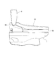
- Publication number
- WO2018128176A1 WO2018128176A1 PCT/JP2018/000009 JP2018000009W WO2018128176A1 WO 2018128176 A1 WO2018128176 A1 WO 2018128176A1 JP 2018000009 W JP2018000009 W JP 2018000009W WO 2018128176 A1 WO2018128176 A1 WO 2018128176A1
- Authority
- WO
- WIPO (PCT)
- Prior art keywords
- toilet seat
- urine
- measuring device
- toilet
- load
- Prior art date
- Legal status (The legal status is an assumption and is not a legal conclusion. Google has not performed a legal analysis and makes no representation as to the accuracy of the status listed.)
- Ceased
Links
Images





Classifications
-
- G—PHYSICS
- G01—MEASURING; TESTING
- G01G—WEIGHING
- G01G19/00—Weighing apparatus or methods adapted for special purposes not provided for in the preceding groups
- G01G19/52—Weighing apparatus combined with other objects, e.g. furniture
-
- A—HUMAN NECESSITIES
- A47—FURNITURE; DOMESTIC ARTICLES OR APPLIANCES; COFFEE MILLS; SPICE MILLS; SUCTION CLEANERS IN GENERAL
- A47K—SANITARY EQUIPMENT; ACCESSORIES THEREFOR, e.g. TOILET ACCESSORIES
- A47K13/00—Seats or covers for all kinds of closets
- A47K13/24—Parts or details not covered in, or of interest apart from, groups A47K13/02 - A47K13/22
-
- A—HUMAN NECESSITIES
- A61—MEDICAL OR VETERINARY SCIENCE; HYGIENE
- A61B—DIAGNOSIS; SURGERY; IDENTIFICATION
- A61B5/00—Measuring for diagnostic purposes; Identification of persons
-
- A—HUMAN NECESSITIES
- A61—MEDICAL OR VETERINARY SCIENCE; HYGIENE
- A61B—DIAGNOSIS; SURGERY; IDENTIFICATION
- A61B5/00—Measuring for diagnostic purposes; Identification of persons
- A61B5/05—Detecting, measuring or recording for diagnosis by means of electric currents or magnetic fields; Measuring using microwaves or radio waves
-
- E—FIXED CONSTRUCTIONS
- E03—WATER SUPPLY; SEWERAGE
- E03D—WATER-CLOSETS OR URINALS WITH FLUSHING DEVICES; FLUSHING VALVES THEREFOR
- E03D9/00—Sanitary or other accessories for lavatories ; Devices for cleaning or disinfecting the toilet room or the toilet bowl; Devices for eliminating smells
-
- G—PHYSICS
- G01—MEASURING; TESTING
- G01G—WEIGHING
- G01G19/00—Weighing apparatus or methods adapted for special purposes not provided for in the preceding groups
- G01G19/44—Weighing apparatus or methods adapted for special purposes not provided for in the preceding groups for weighing persons
-
- G—PHYSICS
- G01—MEASURING; TESTING
- G01G—WEIGHING
- G01G19/00—Weighing apparatus or methods adapted for special purposes not provided for in the preceding groups
- G01G19/44—Weighing apparatus or methods adapted for special purposes not provided for in the preceding groups for weighing persons
- G01G19/50—Weighing apparatus or methods adapted for special purposes not provided for in the preceding groups for weighing persons having additional measuring devices, e.g. for height
-
- G—PHYSICS
- G01—MEASURING; TESTING
- G01N—INVESTIGATING OR ANALYSING MATERIALS BY DETERMINING THEIR CHEMICAL OR PHYSICAL PROPERTIES
- G01N33/00—Investigating or analysing materials by specific methods not covered by groups G01N1/00 - G01N31/00
- G01N33/48—Biological material, e.g. blood, urine; Haemocytometers
- G01N33/483—Physical analysis of biological material
- G01N33/487—Physical analysis of biological material of liquid biological material
- G01N33/48707—Physical analysis of biological material of liquid biological material by electrical means
-
- G—PHYSICS
- G01—MEASURING; TESTING
- G01N—INVESTIGATING OR ANALYSING MATERIALS BY DETERMINING THEIR CHEMICAL OR PHYSICAL PROPERTIES
- G01N33/00—Investigating or analysing materials by specific methods not covered by groups G01N1/00 - G01N31/00
- G01N33/48—Biological material, e.g. blood, urine; Haemocytometers
- G01N33/483—Physical analysis of biological material
- G01N33/487—Physical analysis of biological material of liquid biological material
- G01N33/493—Physical analysis of biological material of liquid biological material urine
Definitions
- the present invention relates to a measuring apparatus.
- This application claims priority on Jan. 06, 2017 based on Japanese Patent Application No. 2017-001098 filed in Japan, the contents of which are incorporated herein by reference.
- a toilet device has been proposed that has a weight measurement function that can measure the weight of a user according to the pressure value detected by the pressure sensor when a pressure sensor is installed on the lower surface of the toilet seat and the user sits on the toilet seat. (See Patent Document 1 below).
- the present invention has been made in view of the above circumstances, and provides a measuring device that can be installed without interfering with the leg portion of a toilet seat installed in a conventional toilet device and that can measure weight. To do.
- the present invention employs the following means. That is, the measuring device according to the first aspect of the present invention is a measuring device that can measure the weight of a user seated on a toilet seat and is installed on a toilet and the toilet seat is installed on the upper side. The load of the user acting on the toilet seat is detected, and a plurality of load detection units are provided so as to protrude upward from the upper surface, and the toilet seat is disposed to protrude downward from the lower surface. A plurality of legs are provided, and the height from the upper surface to the upper end of the load detection unit is higher than the height from the lower surface of the toilet seat to the lower end of the leg unit. The legs are arranged at different positions.
- the measuring apparatus configured as described above has a load detection unit that detects a user's load acting on the toilet seat, and is installed on the toilet.
- a toilet seat is installed on the measuring device. Therefore, the measuring device can be installed on the toilet seat by using the toilet seat installed in the conventional toilet device without changing it.
- the position of the plurality of load detectors provided so as to protrude upward from the upper surface of the measuring device and the plurality of legs provided so as to protrude downward from the lower surface of the toilet seat are different in plan view. Therefore, the load detector and the leg do not interfere with each other in plan view.
- the load detection unit can support the lower surface of the toilet seat, The lower end of the part is not supported on the upper surface of the measuring device. Therefore, the user's load acting on the toilet seat can be accurately measured.
- the plurality of load detection units are arranged apart from each other in the front-rear direction, and the leg portions are disposed between the front and rear load detection units, and You may arrange
- the legs are disposed between the front and rear load detection units and behind the rear load detection unit. Therefore, since the front and rear load detection units are dispersed to support the toilet seat, the toilet seat does not bend downward, and the user's load can be measured more accurately.
- the urine sensor having an electrode capable of electrolyzing urine
- the urine sensor is operated, and the electrode is electrolyzed.
- a control unit that calculates the amount of the component contained in the urine based on the result.
- a urine sensor having an electrode capable of electrolyzing urine, and a control for operating the urine sensor and calculating the amount of components contained in the urine based on the result of electrolysis of the electrode A section. Therefore, not only the weight of the user but also the amount of desired components in urine can be measured.
- a body fat percentage can be measured and a handle that can be gripped may be provided.
- the measuring apparatus configured as described above can measure the body fat percentage and has a handle that can be gripped, and thus can measure not only the weight of the user but also the body fat percentage.
- a first connection port that can be electrically connected to a toilet seat box that supports the toilet seat in an openable and closable manner;
- a second connection port that can be electrically connected to an external power supply may be provided.
- the measuring apparatus configured as described above is provided with a first connection port that can be electrically connected to the toilet seat box and a second connection port that can be electrically connected to an external power source. Therefore, the connection port provided in the existing toilet seat box and the first connection port are electrically connected, and the second connection port and the external power source are electrically connected to supply power to the measuring device and the toilet seat box. can do.
- the cable connected to the connection port provided in the existing toilet seat box is connected to an external power source. When installing the measurement device, remove the cable from the external power supply, connect the cable to the first connection port of the measurement device, and connect the cable connected to the second connection port to the external power supply to measure. Power can be supplied to the device and toilet seat box.
- the measuring apparatus according to the present invention can be installed without interfering with the legs of the toilet seat installed in the conventional toilet apparatus, and can measure the body weight.
- FIG. 1 is a perspective view of a flush toilet equipped with a measuring apparatus according to an embodiment of the present invention.
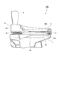
- FIG. 2 is a side view of the measuring apparatus according to the embodiment of the present invention as viewed from the right side.
- FIG. 3 is a vertical sectional view of the measuring apparatus according to the embodiment of the present invention cut along the front-rear direction.
- the flush toilet 100 includes a toilet 1, a toilet seat device 3, and a water purification tank 7.
- the toilet seat device 3 is installed on the toilet 1.
- the toilet seat device 3 includes a measuring device 2, a toilet seat box 6, a toilet seat 8, and a toilet lid 9.
- the direction in which the face of the user sitting on the toilet seat 8 faces is defined as the front
- the direction in which the user sitting on the toilet seat 8 faces is defined as the rear.
- it is the horizontal direction orthogonal to the front-back direction, Comprising:
- the width direction of the flush toilet 100 be a left-right direction. Further, the left side and the right side may be referred to as the side.
- the measuring device 2 is interposed between the toilet 1 and the toilet seat 8. In other words, the measuring device 2 is fixed to the upper surface of the toilet 1, and the toilet seat 8 is disposed on the measuring device 2.
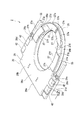
- FIG. 4 is a perspective view of the measuring apparatus 2 as viewed from above.
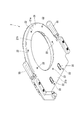
- FIG. 5 is a perspective view of the measuring device 2 as viewed from below.
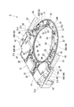
- FIG. 6 is a perspective view of the state in which the upper cover 26 is removed from the measuring device 2 and the urine sensor 30 is disposed at the accommodation position as viewed from above.
- FIG. 7 is a perspective view of the state in which the upper cover 26 is removed from the measurement apparatus 2 and the urine sensor 30 is disposed at the measurement position, as viewed from above.
- the measuring device 2 includes a housing 20 having a substantially O shape in plan view, a urine sensor 30 disposed inside the housing 20, a storage liquid tank 41, and a calibration liquid tank. 46, a urine measurement control unit (control unit) 51, a load cell (load detection unit) 53, and a body fat measurement body (handle) 55.
- the housing 20 has a lower cover 21 that is fixed to the toilet 1 and an upper cover 26 that is provided above the lower cover 21.
- the lower cover 21 and the upper cover 26 are each provided with an opening 20h that is substantially elliptical in plan view.
- the lower cover 21 has an annular portion 21a formed in an annular shape in plan view, and an extending portion 21b extending in the left and right sides and rearward at the rear portion of the annular portion 21a. ing.
- the annular portion 21 a has substantially the same shape as the toilet seat 8 in plan view, and is formed according to the shape of the toilet seat 8.
- the extension part 21b is formed in a shape extending to the left and right outside of the toilet seat 8 in plan view.
- the outer edge of the extending portion 21b includes a front wall portion 21c extending from the rear portion of the annular portion 21a to the left and right sides, a side wall portion 21d extending rearward from the end portion of each front wall portion 21c, and a pair of side wall portions 21d. It is formed of a rear wall portion 21e that connects the end portions and extends in the left-right direction.
- the front wall portion 21c, the side wall portion 21d, and the rear wall portion 21e rise upward from the lower surface of the extending portion 21b.
- An opening 21h having a substantially elliptical shape in plan view is provided inside the annular portion 21a.
- the lower cover 21 has a plurality of mounting holes 22 penetrating in the vertical direction. A screw or a fixture (not shown) is inserted into the attachment hole 22 and screwed into the toilet 1.
- the upper cover 26 is formed in substantially the same shape as the lower cover 21 in plan view.
- the upper cover 26 includes an annular portion 26a formed in an annular shape in plan view, and an extending portion 26b extending in the left and right sides and rearward at the rear portion of the annular portion 26a.
- the outer edges of the extending portions 26b are a front wall portion 26c extending from the rear portion of the annular portion 26a to the left and right sides, a side wall portion 26d extending rearward from the end portion of each front wall portion 26c, and the rear of the pair of side wall portions 26d. It is formed with a rear wall portion 26e that connects the end portions and extends in the left-right direction.
- the front wall part 26c, the side wall part 26d, and the rear wall part 26e are bent downward from the upper surface 26u of the extension part 26b.
- An opening 26h having a substantially elliptical shape in plan view is provided inside the annular portion 26a.
- the opening 26 h of the upper cover 26 communicates with the opening 26 h of the lower cover 21.
- the lower end of the front wall portion 21c of the lower cover 21 is in contact with the upper end of the front wall portion 26c of the upper cover 26, and the lower end of the side wall portion 21d of the lower cover 21 is in contact with the upper end of the side wall portion 26d of the upper cover 26.
- the lower end of the rear wall portion 21e of 21 is in contact with the upper end of the rear wall portion 26e of the upper cover 26.
- a urine sensor 30, a storage liquid tank 41, a calibration liquid tank 46, a urine measurement control unit 51, and a load cell 53 are provided on the upper surface of the lower cover 21.
- the upper cover 26 is provided so as to cover the urine sensor 30, the storage liquid tank 41, the calibration liquid tank 46, the urine measurement control unit 51, and the load cell 53.
- the urine sensor 30, the storage liquid tank 41, the calibration liquid tank 46, the urine measurement control unit 51, and the load cell 53 are accommodated between the lower cover 21 and the upper cover 26.
- the upper surface 26u of the upper cover 26 is formed as a smooth surface.
- each urine sensor 30 includes a base 31 that is pivotably fixed to the lower cover 21, an arm 32 that extends forward from the base 31 and is formed in a hollow shape, and a urine measurement unit that is disposed inside the arm 32. 33.
- the tip of the urine measurement part 33 protrudes from the tip of the arm part 32.
- the urine measurement unit 33 is provided with an electrode (not shown) capable of electrolyzing urine.
- a urine sensor cover 23 is provided at the edge of the opening 21h of the lower cover 21 corresponding to the position where the urine sensor 30 is disposed.
- the urine sensor 30 and the urine sensor cover 23 are connected to a drive motor (not shown).
- the drive motor is driven based on the signal from the urine measurement control unit 51, the urine sensor 30 and the urine sensor cover 23 are moved from a position (accommodation position) arranged on the upper surface of the lower cover 21 as shown in FIG.
- the base 31 is rotated around the base 31 to a position (measurement position) where the tip side protrudes into the opening 21 h of the lower cover 21.
- the urine sensor 30 (see FIG. 6) disposed at the accommodation position is disposed so as to overlap the toilet seat 8 in a plan view (viewed from the arrangement direction of the measuring device 2 and the toilet seat 8).
- the right urine sensor (urine sugar measurement sensor) 30A of the pair of urine sensors 30 can measure urine sugar
- Sensor 30B can measure urinary salt.
- the storage liquid tank 41 is provided on the right side of the lower cover 21.
- the storage liquid tank 41 stores a storage liquid (liquid) for stabilizing the current and voltage of the urine sugar measurement sensor 30A.
- the storage liquid tank 41 is connected to the pump 43 by a tube (not shown).
- the pump 43 is connected to the urine sugar measurement sensor 30A by a tube (not shown). Based on the signal from the urine measurement control unit 51, the pump 43 is driven, and the storage liquid in the storage liquid tank 41 flows through the tube and is supplied to the urine sugar measurement sensor 30A. Thereby, the front-end
- the calibration liquid tank 46 is provided on both the left and right sides of the lower cover 21.
- Calibration fluid for calibrating the urine sugar measurement sensor 30A is stored in the calibration fluid tank 46A on the right side.
- Calibration fluid for calibrating the urinary salt content measuring sensor 30B is stored in the calibration fluid tank 46B on the left side.
- the calibration liquid tank 46A is connected to the pump 48 by a tube (not shown).
- the pump 48 is connected to the urine sugar measurement sensor 30A by a tube (not shown). Based on the signal from the urine measurement control unit 51, the pump 48 is driven, and the calibration liquid in the calibration liquid tank 46A flows through the tube and is supplied to the urine sugar measurement sensor 30A at a predetermined frequency.
- the calibration liquid is dropped into the urine sugar measurement sensor 30A in a container (not shown).
- the calibration liquid tank 46B is connected to the pump 49 by a tube (not shown).
- the pump 49 is connected to the urinary salt measurement sensor 30B by a tube (not shown). Based on the signal from the urine measurement control unit 51, the pump 49 is driven, and the calibration liquid in the calibration liquid tank 46B flows through the tube and is supplied to the urinary salt measurement sensor 30B at a predetermined frequency. As a result, the calibration liquid is dropped into the urinary salt measurement sensor 30B in a container (not shown).
- the storage liquid tank 41 and the calibration liquid tank 46 are each provided with a lid 42 that can be opened and closed.
- each lid 42 is disposed at a position protruding laterally (outside of the left and right sides) of the toilet seat 8 in a plan view.
- each lid 42 is disposed behind the front wall portion 21 c of the lower cover 21.
- each lid 42 is disposed along the upper surface of the extending portion 26 b of the upper cover 26 in the housing 20 installed below the toilet seat 8. Therefore, the user can replenish the storage solution, the calibration solution, and the like by opening and closing the lid 42 without removing the toilet seat 8 (with the toilet seat 8 installed).
- the urine measurement control unit 51 is provided at the rear part of the lower cover 21. Specifically, the urine measurement control unit 51 is disposed along the rear wall portion 21e in front of the rear wall portion 21e in the extending portion 21b of the lower cover 21 in plan view. As shown in FIGS. 1 and 3, the urine measurement control unit 51 is disposed so as to overlap the toilet seat 8 in a plan view (viewed from the arrangement direction of the measuring device 2 and the toilet seat 8). The urine measurement control unit 51 may measure the body weight based on the detection result in the load cell 53 or may measure the body fat percentage based on the detection result in the body fat measurement body 55.
- the urine measurement control unit 51 outputs a signal for driving the pumps 43, 48, and 49, and sends a signal to a drive motor that rotates the urine sensor 30 between the accommodation position and the measurement position.
- the amount of component is calculated based on the result of electrolysis by the urine sensor 30.
- the urine measurement control unit 51 may have a function of transmitting a signal for outputting a measurement value measured by the urine sensor 30 to a display unit (not shown).
- the load cell 53 detects the load of the user acting on the toilet seat 8.
- a plurality of load cells 53 are provided on the lower cover 21 and are electrically connected to the toilet seat box 6.
- the load cells 53 are arranged symmetrically, and are provided at four locations apart from each other in the front-rear direction. In plan view, the load cell 53 is disposed so as to overlap the toilet seat 8.
- the two load cells 53 on the front side are disposed in the vicinity of the front end side (front end side) of the openings 21h and 26h of the toilet seat 8 and are separated in the left-right direction. A front portion of the user's thigh is placed on the load cell 53.
- the two load cells 53 on the rear side are arranged on the left and right sides in the vicinity of the center in the front-rear direction of the openings 21h and 26h of the toilet seat 8, respectively. On the load cell 53, the rear part of the user's thigh is placed.
- the upper cover 26 is provided with a load cell cover (load detection unit) 27 at a position corresponding to the load cell 53. That is, the two load cell covers 27 on the front side are disposed in the vicinity of the front end side (front end side) of the openings 21h and 26h of the toilet seat 8 and are separated in the left-right direction. A front part of the user's thigh is placed on the load cell cover 27.
- the two load cell covers 27 on the rear side are arranged on the left and right sides in the vicinity of the center in the front-rear direction of the openings 21h and 26h of the toilet seat 8, respectively.
- the rear part of the user's thigh is placed on the load cell cover 27.
- the load cell cover 27 is disposed so as to cover the load cell 53 and protrudes upward from the upper surface 26 u of the upper cover 26.
- Each front load cell cover 27 includes an outer curved portion 27a that is curved along the outer edge of the toilet seat 8, an inner curved portion 27b that is curved along the openings 21h and 26h of the toilet seat 8, and an outer side.
- An inner side wall portion 27c that connects the curved portion 27a and the inner curved portion 27b and extends substantially in the front-rear direction; and an outer side wall portion 27d that connects the outer curved portion 27a and the inner curved portion 27b and extends substantially in the left-right direction.
- each load cell cover 27 on the front side is formed in a long shape extending in the left-right direction.
- Each of the rear load cell covers 27 includes an outer curved portion 27e that is curved along the outer edge of the toilet seat 8, an inner curved portion 27f that is curved along the openings 21h and 26h of the toilet seat 8, An inner side wall portion 27g that connects the front end portion of the outer curved portion 27e and the front end portion of the inner curved portion 27f and extends substantially in the left-right direction, and a rear end portion of the outer curved portion 27e and a rear end portion of the inner curved portion 27f are connected. And an outer side wall portion 27h extending substantially in the left-right direction. In plan view, each load cell cover 27 on the rear side is formed in a long shape extending in the front-rear direction.
- the load cell 53 outputs the detected load to the toilet seat box 6 as a load signal. That is, the load applied to the load cell 53 by the user sitting on the toilet seat 8 is converted into an electrical signal by the load cell 53 and transmitted to the toilet seat box 6 as a load signal.
- the body fat measuring body 55 is provided on both the left and right sides of the housing 20. Specifically, the annular portion 21a of the lower cover 21 is provided with a mounting portion 24 in front of the front wall portion 21c and on the inner side in the left-right direction.
- the body fat measurement body 55 includes a base portion 56 that is rotatably fixed to an attachment portion 24 provided on the lower cover 21, and a grip portion 57 that extends from the base portion 56 and can be gripped.
- the body fat measurement body 55 measures the body fat percentage and the like by measuring a resistance by passing a small amount of current through the body by an impedance method or the like by the user gripping the grip portion 57.
- the gripping part 57 can be rotated 90 ° on the plane from the position where the tip shown in FIG. 6 faces forward (accommodating position) to the position where the tip faces sideward (measurement position).
- connection ports 58a and 58b are provided with connection ports 58a and 58b.
- the cable H ⁇ b> 1 connected to the connection port (first connection port) 58 a is connected to the connection port of the toilet seat box 6.
- the cable H2 connected to the connection port (second connection port) 58b is connected to an external power source (not shown).
- the connection ports 58a and 58b are preferably provided at the rear or side of the measuring device.
- the measuring device 2 is provided with water supply ports 59a and 59b.
- the pipe L1 connected to the water supply port 59a is connected to the water supply port 6a of the toilet seat box 6.
- the pipe L2 connected to the water supply port 59b is connected to an external water supply pipe (not shown). It is preferable that the water supply ports 59a and 59b are provided in the rear part or the side of the measuring device.
- the water introduced into the measuring device 2 from the water supply port 59b via the pipe L2 from the external water supply pipe is used for washing the urine sensor 30 and the like.
- the water introduced into the toilet seat box 6 from the water supply port 6a via the pipe L1 from the water supply port 59a of the measuring device 2 is used for local cleaning or the like.
- the toilet seat box 6 is installed on the measuring device 2 in the rear part of the measuring device 2.
- the toilet seat box 6 includes a housing 61, a toilet seat opening / closing mechanism that opens and closes the toilet seat 8 disposed inside the housing 61, a toilet lid opening / closing mechanism that opens and closes the toilet lid 9, and a local cleaning device that cleans a local part of the human body (cleaning Various functional parts (not shown) such as a functional part) and a main body control part (not shown) for controlling these various functional parts.
- the water purification tank 7 As shown in FIG. 1, the water purification tank 7 is fixed behind the toilet seat box 6 on the toilet 1. The water purification tank 7 stores cleaning water for cleaning the toilet bowl 1.
- the toilet seat 8 is formed in a substantially O shape in plan view. The rear part is pivotally supported by the toilet seat box 6 and is rotatable with respect to the toilet 1 between a standing state and a lying state. The toilet seat 8 is installed on the measuring device 2 in a lying state (see FIG. 1).
- FIG. 8 is a perspective view of the toilet seat 8 as viewed from below.
- FIG. 9 is a plan view for illustrating an arrangement relationship between the load cell cover 27 of the measuring device 2 and the leg portion 8e of the toilet seat 8 in the flush toilet 100.
- the lower surface 8d of the toilet seat 8 is provided with a plurality of legs 8e.
- the leg portions 8e are arranged symmetrically, and are provided at four locations apart from each other in the front-rear direction.
- the load cell cover 27 and the leg portion 8e are arranged at different positions in plan view.
- the front leg 8 e is disposed between the front load cell cover 27 and the rear load cell cover 27.
- a rear leg 8e is disposed behind the rear load cell cover 27.
- the height from the upper surface 26u of the upper cover 26 of the measuring device 2 to the upper end of the load cell cover 27 is higher than the height from the lower surface 8d of the toilet seat 8 to the lower end of the leg portion 8e.
- the height in the arrangement direction of the measuring device 2 and the toilet seat 8 from the upper surface 26u of the upper cover 26 of the measuring device 2 to the upper end of the load cell cover 27 is from the lower surface 8d of the toilet seat 8 to the lower end of the leg portion 8e.
- the height in the arrangement direction of the measuring device 2 and the toilet seat 8 is higher.
- the load cell cover 27 can support the lower surface 8d of the toilet seat 8, and the lower end of the leg portion 8e of the toilet seat 8 is not supported by the upper surface 26u of the upper cover 26 of the measuring device 2.
- the toilet lid 9 is pivotally supported by the toilet seat box 6 and is rotatable with respect to the toilet 1 between a standing state and a lying state.
- a seating sensor (not shown) senses it.
- the urine measurement control unit 51 transmits a measurement position movement signal to the drive motor. Accordingly, the drive motor moves the urine sugar measurement sensor 30A, the urinary salt measurement sensor 30B, and the urine sensor cover 23 from the accommodation position to the measurement position. At this time, based on the signal from the urine measurement control unit 51, the gripping portion 57 of the body fat measurement body 55 may be moved from the accommodation position to the measurement position.
- the urine measurement control unit 51 calculates urine sugar and urine salt based on the result of electrolysis.
- a load acts on the load cell 53.
- These loads are converted into electric signals by the load cell 53 and transmitted to the urine measurement control unit 51.
- the urine measurement control unit 51 calculates the weight of the user by summing up the loads represented by these electric signals.
- the urine measurement control unit 51 measures the resistance by flowing a small amount of current through the body by the impedance method or the like, so that the body fat percentage or the like Measure.
- the urine measurement control unit 51 may display these measurement results on a display unit (not shown).
- the measuring device 2 having the load cell 53 for detecting the load of the user acting on the toilet seat 8 is installed on the toilet 1.
- a toilet seat 8 is installed on the measuring device 2. Therefore, the measuring device 2 can be installed on the toilet seat 8 by using the toilet seat 8 installed in the conventional flush toilet 1 as it is without replacing it.
- the plurality of load cells 53 provided so as to protrude upward from the upper surface 26 u of the upper cover 26 of the measuring apparatus 2 and the plurality of legs 8 e provided so as to protrude downward from the lower surface 8 d of the toilet seat 8 are as follows. In plan view (as viewed from the arrangement direction of the measuring device 2 and the toilet seat 8), the load cell 53 and the leg portion 8e do not interfere with each other in plan view because they are arranged at different positions.
- the load cell 53 has the lower surface 8 d of the toilet seat 8. And the lower end of the leg 8e is not supported by the upper surface 26u of the upper cover 26 of the measuring device 2. Therefore, the user's load acting on the toilet seat 8 can be accurately measured.
- leg portion 8e is disposed between the front and rear load cells 53 and behind the rear load cell 53. Therefore, since the front and rear load cells 53 are dispersed to support the toilet seat 8, the toilet seat 8 does not bend downward and the load on the user can be measured more accurately.
- the measuring device 2 operates the urine sensor 30 having an electrode capable of electrolyzing urine, and the urine measurement for calculating the amount of components contained in the urine based on the result of electrolysis of the electrode. And a control unit 51. Therefore, not only the weight of the user but also the amount of desired components in urine can be measured.
- the measuring apparatus 2 since the measuring apparatus 2 includes the body fat measuring body 55 that can measure the body fat percentage and can be gripped, it can measure not only the weight of the user but also the body fat percentage.
- the measuring device 2 is provided with a connection port 58a to which the cable H1 connected to the connection port of the toilet seat box 6 is connected and a connection port 58b to which the cable H2 connected to the external power source is connected. Therefore, the connection port provided in the existing toilet seat box and the connection port 58a are electrically connected, and the connection port 58b and the external power source are electrically connected to supply power to the measuring device 2 and the toilet seat box 6. can do.
- the cable H1 connected to the connection port provided in the existing toilet seat box 6 is connected to an external power source.
- the cable H1 When installing the measuring device 2, the cable H1 is removed from the external power source, the cable H1 is connected to the connection port 58a of the measuring device 2, and the cable H2 connected to the connection port 58b is connected to the external power source. Electric power can be supplied to the measuring device 2 and the toilet seat box 6.
- the load cell 53 is covered with the load cell cover 27, the load cell 53 is not easily soiled.
- the measuring device according to the present invention is not limited to the measuring device 2 according to the above-described embodiment, and appropriate changes and substitutions can be made without departing from the gist of the present invention.
- modifications of the embodiment of the present invention will be described, but the same or similar components and members described in the above-described embodiment will be described using the same reference numerals.
- FIG. 10 is a side view of the measuring apparatus according to the first modification of the embodiment of the present invention as viewed from the right side.
- the toilet seat box 6 is installed on the measurement device 2 at the rear part of the measurement device 2, but as shown in FIG. 10, in the present modification, the toilet seat box 6A is the measurement device 2A. Is located on the toilet 1.
- FIG. 11 is the side view which looked at the measuring apparatus which concerns on the modification 2 of one Embodiment of this invention from the right side.
- the measurement unit 2B has a toilet seat box configuration and a measurement device configuration.
- the toilet seat box and the measuring device are integrally formed.
- the measurement unit 2B includes an annular portion 25a formed in an annular shape in plan view, and a rear body 25b that is provided continuously to the rear portion of the annular portion 25a and is higher than the height of the annular portion 25a in a side view. Yes.
- a tank, a urine measurement control unit, various functional components, a main body control unit, and the like are arranged in the rear body 25b.
- the measuring device concerning the present invention, it can install without interfering with the leg of the toilet seat installed in the conventional toilet device, and the weight can be measured.
Landscapes
- Health & Medical Sciences (AREA)
- Life Sciences & Earth Sciences (AREA)
- Engineering & Computer Science (AREA)
- Biomedical Technology (AREA)
- Physics & Mathematics (AREA)
- Chemical & Material Sciences (AREA)
- General Physics & Mathematics (AREA)
- Urology & Nephrology (AREA)
- Biophysics (AREA)
- Molecular Biology (AREA)
- General Health & Medical Sciences (AREA)
- Pathology (AREA)
- Public Health (AREA)
- Immunology (AREA)
- Analytical Chemistry (AREA)
- Medicinal Chemistry (AREA)
- Food Science & Technology (AREA)
- Hematology (AREA)
- Biochemistry (AREA)
- Animal Behavior & Ethology (AREA)
- Veterinary Medicine (AREA)
- Heart & Thoracic Surgery (AREA)
- Medical Informatics (AREA)
- Surgery (AREA)
- Nuclear Medicine, Radiotherapy & Molecular Imaging (AREA)
- Radiology & Medical Imaging (AREA)
- Epidemiology (AREA)
- Hydrology & Water Resources (AREA)
- Water Supply & Treatment (AREA)
- Toilet Supplies (AREA)
- Bidet-Like Cleaning Device And Other Flush Toilet Accessories (AREA)
- Investigating Or Analysing Biological Materials (AREA)
- Measuring And Recording Apparatus For Diagnosis (AREA)
- Sanitary Device For Flush Toilet (AREA)
Abstract
測定装置は、便座に着座している利用者の体重を測定可能であり、便器上に設置されるとともに、上側に便座が設置される測定装置であって、便座に作用する利用者の荷重を検出するとともに、上面から上方に突出するように配置された複数の荷重検出部を備え、便座には、下面から下方に突出するように配置された複数の脚部が設けられ、上面から荷重検出部の上端までの高さは、便座の下面から脚部の下端までの高さよりも高く、平面視において、荷重検出部は、脚部と位置を異ならせて配置されている。
Description
本発明は、測定装置に関する。
本願は、2017年01月06日に、日本に出願された特願2017-001098号に基づき優先権を主張し、その内容をここに援用する。
本願は、2017年01月06日に、日本に出願された特願2017-001098号に基づき優先権を主張し、その内容をここに援用する。
便座の下面に圧力センサーを設置し、利用者が便座に着座したときに圧力センサーが検出した圧力値に応じて、利用者の体重を測定可能な体重測定機能を備えたトイレ装置が提案されている(下記特許文献1参照)。
しかしながら、従来のトイレ装置に体重測定機能を付加したい場合には、上記の特許文献1に記載のような圧力センサーが設置された便座(専用便座)に交換しないといけないという問題点がある。
また、陶器からなる便器の上面には凹凸等の高低差が生じやすいため、従来の便座の下面には弾性変形可能な脚部が設けられ、この脚部を便器の上面に設置することで便器の上面の高低差を吸収している。よって、便器や便座等に圧力センサーを設置する際には、圧力センサーと便座の脚部との干渉を避けることが望まれている。
また、陶器からなる便器の上面には凹凸等の高低差が生じやすいため、従来の便座の下面には弾性変形可能な脚部が設けられ、この脚部を便器の上面に設置することで便器の上面の高低差を吸収している。よって、便器や便座等に圧力センサーを設置する際には、圧力センサーと便座の脚部との干渉を避けることが望まれている。
そこで、本発明は、上記事情に鑑みてなされたものであり、従来のトイレ装置に設置されている便座の脚部と干渉せずに設置可能であるとともに、体重を測定可能な測定装置を提供する。
上記目的を達成するために、本発明は以下の手段を採用している。
すなわち、本発明の第1態様に係る測定装置は、便座に着座している利用者の体重を測定可能であり、便器上に設置されるとともに、上側に便座が設置される測定装置であって、前記便座に作用する利用者の荷重を検出するとともに、上面から上方に突出するように配置された複数の荷重検出部を備え、前記便座には、下面から下方に突出するように配置された複数の脚部が設けられ、前記上面から前記荷重検出部の上端までの高さは、前記便座の下面から前記脚部の下端までの高さよりも高く、平面視において、前記荷重検出部は、前記脚部と位置を異ならせて配置されている。
すなわち、本発明の第1態様に係る測定装置は、便座に着座している利用者の体重を測定可能であり、便器上に設置されるとともに、上側に便座が設置される測定装置であって、前記便座に作用する利用者の荷重を検出するとともに、上面から上方に突出するように配置された複数の荷重検出部を備え、前記便座には、下面から下方に突出するように配置された複数の脚部が設けられ、前記上面から前記荷重検出部の上端までの高さは、前記便座の下面から前記脚部の下端までの高さよりも高く、平面視において、前記荷重検出部は、前記脚部と位置を異ならせて配置されている。
このように構成された測定装置では、便座に作用する利用者の荷重を検出する荷重検出部を有し、便器上に設置されている。また、便座が、測定装置上に設置されている。よって、従来のトイレ装置に設置されている便座を交換せずにそのまま利用して、便座の上に測定装置を設置することができる。
また、測定装置の上面から上方に突出するように設けられた複数の荷重検出部と、便座の下面から下方に突出するように設けられた複数の脚部とは、平面視において、位置を異ならせて配置されているため、荷重検出部と脚部とは平面視において干渉することがない。
さらに、測定装置の上面から荷重検出部の上端までの高さは、便座の下面から脚部の下端までの高さよりも高いため、荷重検出部は便座の下面を支持することができるとともに、脚部の下端が測定装置の上面に支持されることはない。よって、便座に作用する利用者の荷重を正確に測定することができる。
また、測定装置の上面から上方に突出するように設けられた複数の荷重検出部と、便座の下面から下方に突出するように設けられた複数の脚部とは、平面視において、位置を異ならせて配置されているため、荷重検出部と脚部とは平面視において干渉することがない。
さらに、測定装置の上面から荷重検出部の上端までの高さは、便座の下面から脚部の下端までの高さよりも高いため、荷重検出部は便座の下面を支持することができるとともに、脚部の下端が測定装置の上面に支持されることはない。よって、便座に作用する利用者の荷重を正確に測定することができる。
本発明の第2態様に係る測定装置では、上記第1態様において、複数の前記荷重検出部は、前後方向に離間して配置され、前記脚部は、前後の前記荷重検出部の間、及び後側の前記荷重検出部の後方に配置されていてもよい。
このように構成された測定装置では、脚部は、前後の荷重検出部の間、及び後側の荷重検出部の後方に配置されている。よって、前後の荷重検出部が分散して便座を支持するため、便座が下方に撓んだりすることないとともに、利用者の荷重をより正確に測定することができる。
本発明の第3態様に係る測定装置では、上記第1態様または上記第2態様において、尿を電気分解可能な電極を有する尿センサーと、該尿センサーを作動させるとともに、前記電極が電気分解した結果に基づいて前記尿に含まれる成分の量を演算する制御部と、を備えてもよい。
このように構成された測定装置では、尿を電気分解可能な電極を有する尿センサーと、尿センサーを作動させるとともに、電極が電気分解した結果に基づいて尿に含まれる成分の量を演算する制御部と、を備える。よって、利用者の体重のみならず、尿中の所望の成分の量を測定することができる。
本発明の第4態様に係る測定装置では、上記第1態様から上記第3態様のいずれか一態様において、体脂肪率の測定が可能であるとともに把持可能なハンドルを備えていてもよい。
このように構成された測定装置では、体脂肪率の測定が可能であるとともに把持可能なハンドルを有するため、利用者の体重のみならず、体脂肪率を測定することができる。
本発明の第5態様に係る測定装置では、上記第1態様から上記第4態様のいずれか一態様において、前記便座を開閉自在に支持する便座ボックスと電気的に接続可能な第一接続口及び外部電源と電気的に接続可能な第二接続口が設けられていてもよい。
このように構成された測定装置では、便座ボックスと電気的に接続可能な第一接続口及び外部電源と電気的に接続可能な第二接続口が設けられている。よって、既存の便座ボックスに設けられた接続口と第一接続口とを電気的に接続し、第二接続口と外部電源とを電気的に接続して、測定装置及び便座ボックスに電力を供給することができる。測定装置が設置されていない態様では、既存の便座ボックスに設けられている接続口に接続されたケーブルは、外部電源に接続されている。測定装置を設置する際には、外部電源からケーブルを取り外して、測定装置の第一接続口に当該ケーブルを接続するとともに、第二接続口に接続されたケーブルを外部電源に接続して、測定装置及び便座ボックスに電力を供給することができる。
本発明に係る測定装置によれば、従来のトイレ装置に設置されている便座の脚部と干渉せずに設置可能であるとともに、体重を測定することができる。
本発明の一実施形態である測定装置について説明する。
図1は、本発明の一実施形態に係る測定装置を備えた水洗式便器の斜視図である。図2は、本発明の一実施形態に係る測定装置を右方から見た側面図である。図3は、本発明の一実施形態に係る測定装置を前後方向に沿って切断した鉛直断面図である。
図1から図3に示すように、水洗式便器100は、便器1と、便座装置3と、浄水タンク7と、を備えている。
図1は、本発明の一実施形態に係る測定装置を備えた水洗式便器の斜視図である。図2は、本発明の一実施形態に係る測定装置を右方から見た側面図である。図3は、本発明の一実施形態に係る測定装置を前後方向に沿って切断した鉛直断面図である。
図1から図3に示すように、水洗式便器100は、便器1と、便座装置3と、浄水タンク7と、を備えている。
便座装置3は、便器1の上に設置されている。便座装置3は、測定装置2と、便座ボックス6と、便座8と、便蓋9と、を備えている。
ここで、便座8に着座する利用者の顔が向く方向を前方とし、便座8に着座する利用者の背中が向く方向を後方とする。また、前後方向と直交する水平方向であって水洗式便器100の幅方向を左右方向とする。また、左方及び右方を側方と称する場合がある。
ここで、便座8に着座する利用者の顔が向く方向を前方とし、便座8に着座する利用者の背中が向く方向を後方とする。また、前後方向と直交する水平方向であって水洗式便器100の幅方向を左右方向とする。また、左方及び右方を側方と称する場合がある。
(測定装置)
測定装置2は、便器1と便座8との間に介装されている。換言すると、測定装置2は便器1の上面に固定され、測定装置2の上に便座8が配置されている。
測定装置2は、便器1と便座8との間に介装されている。換言すると、測定装置2は便器1の上面に固定され、測定装置2の上に便座8が配置されている。
図4は、測定装置2を上方から見た斜視図である。図5は、測定装置2を下方から見た斜視図である。図6は、測定装置2から上カバー26が取り外され、尿センサー30が収容位置に配置されている状態を上方から見た斜視図である。図7は、測定装置2から上カバー26が取り外され、尿センサー30が測定位置に配置されている状態を上方から見た斜視図である。
図4から図7に示すように、測定装置2は、平面視略O字状をなす筐体20と、筐体20内部に配置された尿センサー30と、保存液タンク41と、校正液タンク46と、尿測定制御部(制御部)51と、ロードセル(荷重検出部)53と、体脂肪測定体(ハンドル)55と、を備えている。
図4から図7に示すように、測定装置2は、平面視略O字状をなす筐体20と、筐体20内部に配置された尿センサー30と、保存液タンク41と、校正液タンク46と、尿測定制御部(制御部)51と、ロードセル(荷重検出部)53と、体脂肪測定体(ハンドル)55と、を備えている。
筐体20は、便器1に固定される下カバー21と、下カバー21の上方に設けられる上カバー26と、を有している。下カバー21及び上カバー26には、それぞれ平面視略楕円形の開口20hが設けられている。
図5及び図6に示すように、下カバー21は、平面視環状に形成された環状部21aと、環状部21aの後部において、左右両側方及び後方に延びる延出部21bと、を有している。
環状部21aは、平面視において、便座8と略同一形状であり、便座8の形状に応じて形成されている。延出部21bは、平面視において、便座8よりも左右外側に延びた形状に形成されている。
延出部21bの外縁は、環状部21aの後部から左右両側方に延びる前壁部21cと、各前壁部21cの端部から後方に延びる側壁部21dと、及び一対の側壁部21dの後端部どうしを接続し左右方向に延びる後壁部21eとで形成されている。前壁部21c、側壁部21d及び後壁部21eは、延出部21bの下面から上方に立ち上がっている。環状部21aの内側には、平面視略楕円形状の開口21hが設けられている。
下カバー21には、上下方向に貫通する複数の取付孔22が形成されている。取付孔22には、不図示の螺子や取付具が挿通され、便器1に螺合されている。
図4に示すように、平面視において、上カバー26は、下カバー21と略同一の形状に形成されている。上カバー26は、平面視環状に形成された環状部26aと、環状部26aの後部において、左右両側方及び後方に延びる延出部26bと、を有している。
延出部26bの外縁は、環状部26aの後部から左右両側方に延びる前壁部26cと、各前壁部26cの端部から後方に延びる側壁部26dと、及び一対の側壁部26dの後端部どうしを接続し左右方向に延びる後壁部26eとで形成されている。前壁部26c、側壁部26d及び後壁部26eは、延出部26bの上面26uから下方に折曲されている。環状部26aの内側には、平面視略楕円形状の開口26hが設けられている。上カバー26の開口26hは、下カバー21の開口26hと連通している。
下カバー21の前壁部21cの下端は上カバー26の前壁部26cの上端に当接し、下カバー21の側壁部21dの下端は上カバー26の側壁部26dの上端に当接し、下カバー21の後壁部21eの下端は上カバー26の後壁部26eの上端に当接している。
図6に示すように、下カバー21の上面には、尿センサー30、保存液タンク41、校正液タンク46、尿測定制御部51及びロードセル53が設けられている。上カバー26は、尿センサー30、保存液タンク41、校正液タンク46、尿測定制御部51及びロードセル53を覆うように設けられている。換言すると、尿センサー30、保存液タンク41、校正液タンク46、尿測定制御部51及びロードセル53は、下カバー21と上カバー26との間に収容されている。図4に示すように上カバー26の上面26uは、平滑面で形成されている。
図6に示すように、尿センサー30は、下カバー21の環状部21aの左右両側にそれぞれ設けられている。各尿センサー30は、下カバー21に回動可能に固定された基部31と、基部31から前方に延び中空状に形成されたアーム部32と、アーム部32の内部に配置された尿測定部33と、を有している。
尿測定部33の先端は、アーム部32の先端よりも突出している。尿測定部33には、尿を電気分解可能な電極(不図示)が設けられている。
下カバー21の開口21hの縁には、尿センサー30が配置される位置に対応して、尿センサーカバー23が設けられている。
尿センサー30及び尿センサーカバー23は、不図示の駆動モータに接続されている。
尿測定制御部51からの信号に基づいて駆動モータが駆動することにより、尿センサー30及び尿センサーカバー23は、図6に示すように下カバー21の上面に配置される位置(収容位置)から、図7に示すように先端側が下カバー21の開口21hに突出した位置(測定位置)まで、基部31を中心に回動する。平面視において(測定装置2と便座8との配列方向から見て)、収容位置に配置された尿センサー30(図6参照)は、便座8と重なって配置されている。
図6に示すように、本実施形態では、一対の尿センサー30のうち右側の尿センサー(尿糖測定用センサー)30Aは尿糖の測定が可能であり、左側の尿センサー(尿塩分測定用センサー)30Bは尿塩分の測定が可能である。
尿測定制御部51からの信号に基づいて駆動モータが駆動することにより、尿センサー30及び尿センサーカバー23は、図6に示すように下カバー21の上面に配置される位置(収容位置)から、図7に示すように先端側が下カバー21の開口21hに突出した位置(測定位置)まで、基部31を中心に回動する。平面視において(測定装置2と便座8との配列方向から見て)、収容位置に配置された尿センサー30(図6参照)は、便座8と重なって配置されている。
図6に示すように、本実施形態では、一対の尿センサー30のうち右側の尿センサー(尿糖測定用センサー)30Aは尿糖の測定が可能であり、左側の尿センサー(尿塩分測定用センサー)30Bは尿塩分の測定が可能である。
保存液タンク41は、下カバー21の右側に設けられている。保存液タンク41には、尿糖測定用センサー30Aの電流や電圧を安定させるための保存液(液体)が貯留されている。保存液タンク41は、ポンプ43とチューブ(不図示)によって接続されている。ポンプ43は、チューブ(不図示)によって尿糖測定用センサー30Aと接続されている。尿測定制御部51からの信号に基づいて、ポンプ43が駆動し、保存液タンク41内の保存液がチューブを流通して、尿糖測定用センサー30Aに供給される。これにより、尿糖測定用センサー30Aの先端部は、不図示の容器内で保存液に浸されている。
校正液タンク46は、下カバー21の左右両側に設けられている。右側の校正液タンク46Aには、尿糖測定用センサー30Aの校正を行う校正液が貯留されている。左側の校正液タンク46Bには、尿塩分測定用センサー30Bの校正を行う校正液が貯留されている。校正液タンク46Aは、チューブ(不図示)によってポンプ48と接続されている。ポンプ48は、チューブ(不図示)によって尿糖測定用センサー30Aと接続されている。尿測定制御部51からの信号に基づいて、ポンプ48が駆動し、校正液タンク46A内の校正液がチューブを流通して、所定頻度で尿糖測定用センサー30Aに供給される。これにより、尿糖測定用センサー30Aには、不図示の容器内で校正液が滴下される。また、校正液タンク46Bは、チューブ(不図示)によってポンプ49と接続されている。ポンプ49は、チューブ(不図示)によって尿塩分測定用センサー30Bと接続されている。尿測定制御部51からの信号に基づいて、ポンプ49が駆動し、校正液タンク46B内の校正液がチューブを流通して、所定頻度で尿塩分測定用センサー30Bに供給される。これにより、尿塩分測定用センサー30Bには、不図示の容器内で校正液が滴下される。
保存液タンク41及び校正液タンク46には、それぞれ開閉可能な蓋42が設けられている。具体的には、図1に示すように、平面視において、各蓋42は、便座8の側方(左右外側)に突出した位置に配置されている。換言すると、図6に示すように、各蓋42は、下カバー21の前壁部21cの後方に配置されている。図4に示すように、各蓋42は、便座8の下方に設置される筐体20において、上カバー26の延出部26bの上面に沿って配置されている。このため、利用者は、便座8を取り外すことなく(便座8を設置したまま)、蓋42を開閉して、保存液や校正液等を補充することができる。
尿測定制御部51は、下カバー21の後部に設けられている。具体的には、尿測定制御部51は、平面視において、下カバー21の延出部21bにおいて後壁部21eの前方に後壁部21eに沿って配置されている。図1及び図3に示すように、平面視において(測定装置2と便座8との配列方向から見て)、尿測定制御部51は、便座8と重なって配置されている。また、尿測定制御部51は、ロードセル53での検出結果に基づいて体重を測定してもよいし、体脂肪測定体55での検出結果に基づいて体脂肪率を測定してもよい。
図6に示すように、尿測定制御部51は、ポンプ43,48,49を駆動させる信号を出力したり、尿センサー30を収容位置と測定位置との間で回動させる駆動モータへ信号を出力したり、尿センサー30で電気分解した結果に基づいて成分の量を演算したりする。また、尿測定制御部51は、不図示の表示部に、尿センサー30で測定した測定値を出力する信号を送信する機能を有していてもよい。
ロードセル53は、便座8に作用する利用者の荷重を検出する。ロードセル53は、下カバー21に複数設けられ、便座ボックス6に電気的に接続されている。
本実施形態では、ロードセル53は、左右対称に配置されるとともに、前後方向に互いに離間して、4箇所に設けられている。平面視において、ロードセル53は、便座8と重なって配置されている。
前側の2箇所のロードセル53は、便座8の開口21h、26hの先端側(前端側)近傍に、左右方向に離間して配置されている。ロードセル53には、利用者の太腿の前部が載置される。後側の2箇所のロードセル53は、便座8の開口21h、26hの前後方向の中央近傍に、左右それぞれに配置されている。ロードセル53には、利用者の太腿の後部が載置される。
図4に示すように、上カバー26には、ロードセル53と対応する位置にロードセルカバー(荷重検出部)27が設けられている。つまり、前側の2箇所のロードセルカバー27は、便座8の開口21h、26hの先端側(前端側)近傍に、左右方向に離間して配置されている。ロードセルカバー27には、利用者の太腿の前部が載置される。後側の2箇所のロードセルカバー27は、便座8の開口21h、26hの前後方向の中央近傍に、左右それぞれに配置されている。ロードセルカバー27には、利用者の太腿の後部が載置される。
ロードセルカバー27は、ロードセル53を覆うように配置され、上カバー26の上面26uから上方に突出している。
前側の各ロードセルカバー27は、便座8の外縁に沿って湾曲して形成された外側湾曲部27aと、便座8の開口21h,26hに沿って湾曲して形成された内側湾曲部27bと、外側湾曲部27aと内側湾曲部27bとを接続し略前後方向に延びる内側側壁部27cと、外側湾曲部27aと内側湾曲部27bとを接続し略左右方向に延びる外側側壁部27dと、を有している。平面視において、前側の各ロードセルカバー27は、左右方向に延びる長い形状に形成されている。
後側の各ロードセルカバー27は、便座8の外縁に沿って湾曲して形成された外側湾曲部27eと、便座8の開口21h,26hに沿って湾曲して形成された内側湾曲部27fと、外側湾曲部27eの前端部と内側湾曲部27fの前端部とを接続し略左右方向に延びる内側側壁部27gと、外側湾曲部27eの後端部と内側湾曲部27fの後端部とを接続し略左右方向に延びる外側側壁部27hと、を有している。平面視において、後側の各ロードセルカバー27は、前後方向に延びる長い形状に形成されている。
ロードセル53は、検出した荷重を荷重信号として便座ボックス6に出力する。すなわち、利用者が便座8に着座することでロードセル53に作用した荷重は、それぞれロードセル53で電気信号に変換されて荷重信号として便座ボックス6に送信される。
体脂肪測定体55は、筐体20の左右両側に設けられている。具体的には、下カバー21の環状部21aには、前壁部21cよりも前方且つ左右方向の内側に取付部24が設けられている。体脂肪測定体55は、下カバー21に設けられた取付部24に回動自在に固定される基部56と、基部56から延び把持可能な把持部57と、を有している。体脂肪測定体55は、利用者が把持部57を把持することで、インピーダンス法等により、身体に微量の電流を流して抵抗を測定することにより、体脂肪率等を測定する。把持部57は、図6に示す先端が前方を向いた位置(収容位置)から平面上を90°回動して、先端が側方を向けた位置(測定位置)まで回動可能である。
図2に示すように、測定装置2には接続口58a,58bが設けられている。接続口(第一接続口)58aに接続されたケーブルH1は、便座ボックス6の接続口に接続されている。接続口(第二接続口)58bに接続されたケーブルH2は、外部電源(不図示)に接続されている。接続口58a,58bは、測定装置の後部や側方に設けられていることが好ましい。
測定装置2には給水口59a,59bが設けられている。給水口59aに接続された配管L1は、便座ボックス6の給水口6aに接続されている。給水口59bに接続された配管L2は、外部給水管(不図示)に接続されている。給水口59a,59bは、測定装置の後部や側方に設けられていることが好ましい。外部給水管から配管L2を経由して給水口59bから測定装置2内に導入された水は、尿センサー30の洗浄等に使用される。また、測定装置2の給水口59aから配管L1を経由して給水口6aから便座ボックス6に導入された水は、局部洗浄等に使用される。
(便座ボックス)
図3に示すように、便座ボックス6は、測定装置2の後部において、測定装置2上に設置されている。便座ボックス6は、筐体61と、筐体61の内部に配置され便座8を開閉する便座開閉機構、便蓋9を開閉する便蓋開閉機構、及び人体の局部を洗浄する局部洗浄装置(洗浄機能部)等の各種機能部品(不図示)と、これら各種機能部品を制御する本体制御部(不図示)と、を備えている。
図3に示すように、便座ボックス6は、測定装置2の後部において、測定装置2上に設置されている。便座ボックス6は、筐体61と、筐体61の内部に配置され便座8を開閉する便座開閉機構、便蓋9を開閉する便蓋開閉機構、及び人体の局部を洗浄する局部洗浄装置(洗浄機能部)等の各種機能部品(不図示)と、これら各種機能部品を制御する本体制御部(不図示)と、を備えている。
(浄水タンク)
図1に示すように、浄水タンク7は、便器1上において便座ボックス6よりも後方に固定されている。浄水タンク7は、便器1洗浄用の洗浄水を貯留している。
図1に示すように、浄水タンク7は、便器1上において便座ボックス6よりも後方に固定されている。浄水タンク7は、便器1洗浄用の洗浄水を貯留している。
(便座)
便座8は、平面視略O字状に形成されている。後部が便座ボックス6に軸支されており、便器1に対して起立状態と倒伏状態との間で回動自在である。便座8は、倒伏状態(図1参照)で、測定装置2上に設置されている。
便座8は、平面視略O字状に形成されている。後部が便座ボックス6に軸支されており、便器1に対して起立状態と倒伏状態との間で回動自在である。便座8は、倒伏状態(図1参照)で、測定装置2上に設置されている。
図8は、便座8を下方から見た斜視図である。図9は、水洗式便器100において、測定装置2のロードセルカバー27と便座8の脚部8eとの配置関係を示すための平面図である。
図8に示すように、便座8の下面8dには、複数の脚部8eが設けられている。本実施形態では、脚部8eは、左右対称に配置されるとともに、前後方向に互いに離間して、4箇所に設けられている。
図8に示すように、便座8の下面8dには、複数の脚部8eが設けられている。本実施形態では、脚部8eは、左右対称に配置されるとともに、前後方向に互いに離間して、4箇所に設けられている。
図9に示すように、ロードセルカバー27と脚部8eとは、平面視において、位置を異ならせて配置されている。換言すると、前側のロードセルカバー27と後側のロードセルカバー27との間に、前側の脚部8eが配置されている。後側のロードセルカバー27の後方に、後側の脚部8eが配置されている。
また、図2に示す側面視において、測定装置2の上カバー26の上面26uからロードセルカバー27の上端までの高さは、便座8の下面8dから脚部8eの下端までの高さよりも高い。言い換えると、測定装置2の上カバー26の上面26uからロードセルカバー27の上端までの、測定装置2と便座8との配列方向の高さは、便座8の下面8dから脚部8eの下端までの、測定装置2と便座8との配列方向の高さよりも高い。これにより、ロードセルカバー27は便座8の下面8dを支持することができるとともに、便座8の脚部8eの下端が測定装置2の上カバー26の上面26uに支持されることはない。
(便蓋)
便蓋9は、便座ボックス6に軸支されており、便器1に対して起立状態と倒伏状態との間で回動自在である。
便蓋9は、便座ボックス6に軸支されており、便器1に対して起立状態と倒伏状態との間で回動自在である。
次に、上記のように構成された水洗式便器100における測定装置2の動作について説明する。
利用者が便座8に着座すると、不図示の着座センサーが感知する。尿測定制御部51は駆動モータに測定位置移動信号を送信する。これにより、駆動モータは尿糖測定用センサー30A、尿塩分測定用センサー30B及び尿センサーカバー23を収容位置から測定位置まで移動させる。この際に、尿測定制御部51の信号に基づいて、体脂肪測定体55の把持部57が、収容位置から測定位置まで移動する構成であってもよい。
利用者が便座8に着座すると、不図示の着座センサーが感知する。尿測定制御部51は駆動モータに測定位置移動信号を送信する。これにより、駆動モータは尿糖測定用センサー30A、尿塩分測定用センサー30B及び尿センサーカバー23を収容位置から測定位置まで移動させる。この際に、尿測定制御部51の信号に基づいて、体脂肪測定体55の把持部57が、収容位置から測定位置まで移動する構成であってもよい。
利用者は排尿すると、尿糖測定用センサー30A及び尿塩分測定用センサー30Bの電極がそれぞれ電気分解する。尿測定制御部51は、電気分解の結果に基づいて、尿糖及び尿塩分を演算する。
一方、利用者が便座8に座ると、ロードセル53に荷重が作用する。これらの荷重は、それぞれロードセル53で電気信号に変換されて、尿測定制御部51に送信される。尿測定制御部51は、これらの電気信号が表す荷重を合計して、利用者の体重を演算する。
また、利用者が、体脂肪測定体55の把持部57を把持すると、尿測定制御部51は、インピーダンス法等により、身体に微量の電流を流して抵抗を測定することにより、体脂肪率等を測定する。
尿測定制御部51は、これらの測定結果を不図示の表示部に表示してもよい。
尿測定制御部51は、これらの測定結果を不図示の表示部に表示してもよい。
このように構成された水洗式便器100では、便座8に作用する利用者の荷重を検出するロードセル53を有する測定装置2が、便器1上に設置されている。また、便座8が、測定装置2上に設置されている。よって、従来の水洗式便器1に設置されている便座8を交換せずにそのまま利用して、便座8の上に測定装置2を設置することができる。
また、測定装置2の上カバー26の上面26uから上方に突出するように設けられた複数のロードセル53と、便座8の下面8dから下方に突出するように設けられた複数の脚部8eとは、平面視において(測定装置2と便座8との配列方向から見て)、位置を異ならせて配置されているため、ロードセル53と脚部8eとは平面視において干渉することがない。
さらに、測定装置2の上カバー26の上面26uからロードセル53の上端までの高さは、便座8の下面8dから脚部8eの下端までの高さよりも高いため、ロードセル53は便座8の下面8dを支持することができるとともに、脚部8eの下端が測定装置2の上カバー26の上面26uに支持されることはない。よって、便座8に作用する利用者の荷重を正確に測定することができる。
また、脚部8eは、前後のロードセル53の間、及び後側のロードセル53の後方に配置されている。よって、前後のロードセル53が分散して便座8を支持するため、便座8が下方に撓んだりすることないとともに、利用者の荷重をより正確に測定することができる。
また、測定装置2は、尿を電気分解可能な電極を有する尿センサー30と、尿センサー30を作動させるとともに、電極が電気分解した結果に基づいて尿に含まれる成分の量を演算する尿測定制御部51と、を備える。よって、利用者の体重のみならず、尿中の所望の成分の量を測定することができる。
また、測定装置2は、体脂肪率の測定が可能であるとともに把持可能な体脂肪測定体55を有するため、利用者の体重のみならず、体脂肪率を測定することができる。
また、測定装置2には、便座ボックス6の接続口に接続されたケーブルH1が接続される接続口58a、及び外部電源に接続されたケーブルH2が接続される接続口58bが設けられている。よって、既存の便座ボックスに設けられた接続口と接続口58aとを電気的に接続し、接続口58bと外部電源とを電気的に接続して、測定装置2及び便座ボックス6に電力を供給することができる。測定装置2が設置されていない態様では、既存の便座ボックス6に設けられている接続口に接続されたケーブルH1は、外部電源に接続されている。測定装置2を設置する際には、外部電源からケーブルH1を取り外して、測定装置2の接続口58aにケーブルH1を接続するとともに、接続口58bに接続されたケーブルH2を外部電源に接続して、測定装置2及び便座ボックス6に電力を供給することができる。
また、ロードセル53はロードセルカバー27で覆われているため、ロードセル53が汚れにくい。
なお、本発明に係る測定装置、上述した実施形態に係る測定装置2に限定されるものではなく、本発明の要旨を逸脱しない範囲で適宜の変更や置換等が可能である。
以下に、本発明の実施形態の変形例について説明するが、上述した実施形態で説明した部品や部材等と同一または同様なものについては、同一の符号を用いて説明する。
以下に、本発明の実施形態の変形例について説明するが、上述した実施形態で説明した部品や部材等と同一または同様なものについては、同一の符号を用いて説明する。
(変形例1)
次に、本発明の一実施形態の変形例1に係る測定装置について、主に図10に基づいて説明する。
図10は、本発明の一実施形態の変形例1に係る測定装置を右方から見た側面図である。
上記に示す実施形態では、便座ボックス6は、測定装置2の後部において、測定装置2上に設置されているが、図10に示すように、本変形例では、便座ボックス6Aは、測定装置2Aの後方に位置し、便器1上に設置されている。
次に、本発明の一実施形態の変形例1に係る測定装置について、主に図10に基づいて説明する。
図10は、本発明の一実施形態の変形例1に係る測定装置を右方から見た側面図である。
上記に示す実施形態では、便座ボックス6は、測定装置2の後部において、測定装置2上に設置されているが、図10に示すように、本変形例では、便座ボックス6Aは、測定装置2Aの後方に位置し、便器1上に設置されている。
(変形例2)
次に、本発明の一実施形態の変形例2に係る測定装置について、主に図11に基づいて説明する。
図11は、本発明の一実施形態の変形例2に係る測定装置を右方から見た側面図である。
図11に示すように、本変形例では、測定ユニット2Bは、便座ボックスの構成と測定装置の構成とを有している。換言すると、便座ボックスと測定装置とは一体として形成されている。測定ユニット2Bは、平面視環状に形成された環状部25aと、環状部25aの後部に連続して設けられ、側面視において、環状部25aの高さよりも高い後部体25bと、を有している。後部体25bには、タンク、尿測定制御部、各種機能部品及び本体制御部等が配置されている。
次に、本発明の一実施形態の変形例2に係る測定装置について、主に図11に基づいて説明する。
図11は、本発明の一実施形態の変形例2に係る測定装置を右方から見た側面図である。
図11に示すように、本変形例では、測定ユニット2Bは、便座ボックスの構成と測定装置の構成とを有している。換言すると、便座ボックスと測定装置とは一体として形成されている。測定ユニット2Bは、平面視環状に形成された環状部25aと、環状部25aの後部に連続して設けられ、側面視において、環状部25aの高さよりも高い後部体25bと、を有している。後部体25bには、タンク、尿測定制御部、各種機能部品及び本体制御部等が配置されている。
なお、上述した実施の形態において示した組立手順、あるいは各構成部材の諸形状や組み合わせ等は一例であって、本発明の主旨から逸脱しない範囲において設計要求等に基づき種々変更可能である。
その他、本発明の趣旨を逸脱しない範囲で、上記した実施形態における構成要素を周知の構成要素に置き換えることは適宜可能である。
また、本発明は前述した説明によって限定されることはなく、添付の請求の範囲によってのみ限定される。
その他、本発明の趣旨を逸脱しない範囲で、上記した実施形態における構成要素を周知の構成要素に置き換えることは適宜可能である。
また、本発明は前述した説明によって限定されることはなく、添付の請求の範囲によってのみ限定される。
本発明に係る測定装置によれば、従来のトイレ装置に設置されている便座の脚部と干渉せずに設置可能であるとともに、体重を測定することができる。
1…便器
2…測定装置
6…便座ボックス
7…浄水タンク
8…便座
9…便蓋
20…筐体
21…下カバー
22…取付孔
23…尿センサーカバー
26…上カバー
27…ロードセルカバー(荷重検出部)
21h,26h…開口
30…尿センサー
31…基部
32…アーム部
33…尿測定部
41…保存液タンク
42…蓋
43…ポンプ
46…校正液タンク
51…尿測定制御部(制御部)
53…ロードセル(荷重検出部)
55…体脂肪測定体(ハンドル)
56…基部
57…把持部
100…水洗式便器
2…測定装置
6…便座ボックス
7…浄水タンク
8…便座
9…便蓋
20…筐体
21…下カバー
22…取付孔
23…尿センサーカバー
26…上カバー
27…ロードセルカバー(荷重検出部)
21h,26h…開口
30…尿センサー
31…基部
32…アーム部
33…尿測定部
41…保存液タンク
42…蓋
43…ポンプ
46…校正液タンク
51…尿測定制御部(制御部)
53…ロードセル(荷重検出部)
55…体脂肪測定体(ハンドル)
56…基部
57…把持部
100…水洗式便器
Claims (5)
- 便座に着座している利用者の体重を測定可能であり、便器上に設置されるとともに、上側に便座が設置される測定装置であって、
前記便座に作用する利用者の荷重を検出するとともに、上面から上方に突出するように配置された複数の荷重検出部を備え、
前記便座には、下面から下方に突出するように配置された複数の脚部が設けられ、
前記上面から前記荷重検出部の上端までの高さは、前記便座の下面から前記脚部の下端までの高さよりも高く、
平面視において、前記荷重検出部は、前記脚部と位置を異ならせて配置されている測定装置。 - 複数の前記荷重検出部は、前後方向に離間して配置され、
前記脚部は、前後の前記荷重検出部の間、及び後側の前記荷重検出部の後方に配置されている請求項1に記載の測定装置。 - 尿を電気分解可能な電極を有する尿センサーと、
前記尿センサーを作動させるとともに、前記電極が電気分解した結果に基づいて前記尿に含まれる成分の量を演算する制御部と、を備える請求項1または2に記載の測定装置。 - 体脂肪率の測定が可能であるとともに把持可能なハンドルを備える請求項1から3のいずれか一項に記載の測定装置。
- 前記便座を開閉自在に支持する便座ボックスと電気的に接続可能な第一接続口及び外部電源と電気的に接続可能な第二接続口が設けられている請求項1から4のいずれか一項に記載の測定装置。
Priority Applications (3)
| Application Number | Priority Date | Filing Date | Title |
|---|---|---|---|
| US16/475,977 US20190323880A1 (en) | 2017-01-06 | 2018-01-04 | Measuring device |
| DE112018000322.1T DE112018000322T5 (de) | 2017-01-06 | 2018-01-04 | Messvorrichtung |
| CN201880005750.4A CN110139590A (zh) | 2017-01-06 | 2018-01-04 | 测定装置 |
Applications Claiming Priority (2)
| Application Number | Priority Date | Filing Date | Title |
|---|---|---|---|
| JP2017001098A JP2018110607A (ja) | 2017-01-06 | 2017-01-06 | 測定装置 |
| JP2017-001098 | 2017-01-06 |
Publications (1)
| Publication Number | Publication Date |
|---|---|
| WO2018128176A1 true WO2018128176A1 (ja) | 2018-07-12 |
Family
ID=62789492
Family Applications (1)
| Application Number | Title | Priority Date | Filing Date |
|---|---|---|---|
| PCT/JP2018/000009 Ceased WO2018128176A1 (ja) | 2017-01-06 | 2018-01-04 | 測定装置 |
Country Status (5)
| Country | Link |
|---|---|
| US (1) | US20190323880A1 (ja) |
| JP (1) | JP2018110607A (ja) |
| CN (1) | CN110139590A (ja) |
| DE (1) | DE112018000322T5 (ja) |
| WO (1) | WO2018128176A1 (ja) |
Cited By (1)
| Publication number | Priority date | Publication date | Assignee | Title |
|---|---|---|---|---|
| EP4400012A3 (de) * | 2023-01-10 | 2024-09-18 | Oceanwell (Xiamen) Industrial Co., Ltd. | Kabelführungsanordnung zur stromversorgung einer toilettenabdeckung |
Families Citing this family (2)
| Publication number | Priority date | Publication date | Assignee | Title |
|---|---|---|---|---|
| KR102031019B1 (ko) * | 2018-03-23 | 2019-10-11 | 토토 가부시키가이샤 | 변좌 장치 |
| JP2024095358A (ja) * | 2022-12-28 | 2024-07-10 | 株式会社Lixil | 体重測定装置 |
Citations (4)
| Publication number | Priority date | Publication date | Assignee | Title |
|---|---|---|---|---|
| JPH08304159A (ja) * | 1995-05-11 | 1996-11-22 | Katsuji Ichii | 便座体重測定装置 |
| JPH09119859A (ja) * | 1995-10-26 | 1997-05-06 | Matsushita Electric Ind Co Ltd | 体重計 |
| JP2000254040A (ja) * | 1999-03-11 | 2000-09-19 | Matsushita Electric Ind Co Ltd | 便 座 |
| JP2014206002A (ja) * | 2013-04-12 | 2014-10-30 | 株式会社Lixil | 便器用体重計及びそれを取り付けた便器 |
Family Cites Families (4)
| Publication number | Priority date | Publication date | Assignee | Title |
|---|---|---|---|---|
| JPS601397U (ja) * | 1983-06-17 | 1985-01-08 | 東陶機器株式会社 | 便所装置 |
| JP3063245B2 (ja) | 1991-06-14 | 2000-07-12 | 東陶機器株式会社 | 体重測定機能を備えた便器 |
| JP3304587B2 (ja) * | 1993-12-30 | 2002-07-22 | 東陶機器株式会社 | トイレット設置型尿分析ユニット |
| JP6198162B2 (ja) | 2016-08-05 | 2017-09-20 | 住友電気工業株式会社 | マグネシウム合金コイル材の製造方法 |
-
2017
- 2017-01-06 JP JP2017001098A patent/JP2018110607A/ja active Pending
-
2018
- 2018-01-04 CN CN201880005750.4A patent/CN110139590A/zh active Pending
- 2018-01-04 US US16/475,977 patent/US20190323880A1/en not_active Abandoned
- 2018-01-04 WO PCT/JP2018/000009 patent/WO2018128176A1/ja not_active Ceased
- 2018-01-04 DE DE112018000322.1T patent/DE112018000322T5/de not_active Withdrawn
Patent Citations (4)
| Publication number | Priority date | Publication date | Assignee | Title |
|---|---|---|---|---|
| JPH08304159A (ja) * | 1995-05-11 | 1996-11-22 | Katsuji Ichii | 便座体重測定装置 |
| JPH09119859A (ja) * | 1995-10-26 | 1997-05-06 | Matsushita Electric Ind Co Ltd | 体重計 |
| JP2000254040A (ja) * | 1999-03-11 | 2000-09-19 | Matsushita Electric Ind Co Ltd | 便 座 |
| JP2014206002A (ja) * | 2013-04-12 | 2014-10-30 | 株式会社Lixil | 便器用体重計及びそれを取り付けた便器 |
Cited By (1)
| Publication number | Priority date | Publication date | Assignee | Title |
|---|---|---|---|---|
| EP4400012A3 (de) * | 2023-01-10 | 2024-09-18 | Oceanwell (Xiamen) Industrial Co., Ltd. | Kabelführungsanordnung zur stromversorgung einer toilettenabdeckung |
Also Published As
| Publication number | Publication date |
|---|---|
| CN110139590A (zh) | 2019-08-16 |
| JP2018110607A (ja) | 2018-07-19 |
| DE112018000322T5 (de) | 2019-09-19 |
| US20190323880A1 (en) | 2019-10-24 |
Similar Documents
| Publication | Publication Date | Title |
|---|---|---|
| WO2018128176A1 (ja) | 測定装置 | |
| KR101906904B1 (ko) | 적응형 자동식 변기 | |
| WO1995018374A1 (fr) | Procede et dispositif de prelevement d'echantillons d'urine | |
| KR102145998B1 (ko) | 양변기용 살균장치 | |
| US20150040303A1 (en) | Toilet provided with urine splash prevention apparatus | |
| CN101095633A (zh) | 自动收尿装置 | |
| JP5966095B1 (ja) | 内視鏡リプロセッサ | |
| JP5229699B1 (ja) | トイレ装置 | |
| JP6214078B2 (ja) | 便器用体重計及びそれを取り付けた便器 | |
| JP6831077B2 (ja) | 測定装置 | |
| RU2009102862A (ru) | Устройство, облегчающее ходьбу | |
| PT1870011E (pt) | Balde para esfregona | |
| JP2012152256A (ja) | 可搬便器 | |
| JPH07198660A (ja) | トイレット設置型尿分析ユニット | |
| JP2018111918A (ja) | トイレ装置 | |
| KR20130092024A (ko) | 멜로디 유아용 소변기 | |
| JP2021141961A (ja) | 便器装置 | |
| JP3422125B2 (ja) | 感温素子付き採尿容器を備えた尿分析装置 | |
| JP6753668B2 (ja) | 便器洗浄タンク | |
| JP6509068B2 (ja) | 便座 | |
| JP2021141962A (ja) | 便器装置 | |
| JP2000126088A (ja) | 体脂肪測定便座 | |
| KR20150022496A (ko) | 변기의 자동배수장치 | |
| JP3618607B2 (ja) | 温水洗浄便座 | |
| CN217471873U (zh) | 洗地机基站及手持式洗地设备 |
Legal Events
| Date | Code | Title | Description |
|---|---|---|---|
| 121 | Ep: the epo has been informed by wipo that ep was designated in this application |
Ref document number: 18736587 Country of ref document: EP Kind code of ref document: A1 |
|
| 122 | Ep: pct application non-entry in european phase |
Ref document number: 18736587 Country of ref document: EP Kind code of ref document: A1 |