WO2018128162A1 - Dispositif d'éclairage - Google Patents
Dispositif d'éclairage Download PDFInfo
- Publication number
- WO2018128162A1 WO2018128162A1 PCT/JP2017/047233 JP2017047233W WO2018128162A1 WO 2018128162 A1 WO2018128162 A1 WO 2018128162A1 JP 2017047233 W JP2017047233 W JP 2017047233W WO 2018128162 A1 WO2018128162 A1 WO 2018128162A1
- Authority
- WO
- WIPO (PCT)
- Prior art keywords
- laser light
- optical element
- diffractive optical
- light source
- area
- Prior art date
Links
- 230000003287 optical effect Effects 0.000 claims abstract description 190
- 230000004907 flux Effects 0.000 claims abstract description 80
- 238000005286 illumination Methods 0.000 claims description 53
- 238000007493 shaping process Methods 0.000 claims description 29
- 230000007423 decrease Effects 0.000 description 4
- 230000005855 radiation Effects 0.000 description 4
- XLYOFNOQVPJJNP-UHFFFAOYSA-N water Substances O XLYOFNOQVPJJNP-UHFFFAOYSA-N 0.000 description 4
- 239000000654 additive Substances 0.000 description 3
- 230000000996 additive effect Effects 0.000 description 3
- 238000009792 diffusion process Methods 0.000 description 3
- 239000000463 material Substances 0.000 description 3
- 230000008901 benefit Effects 0.000 description 2
- 230000001427 coherent effect Effects 0.000 description 2
- 239000003086 colorant Substances 0.000 description 2
- 238000004519 manufacturing process Methods 0.000 description 2
- 230000004048 modification Effects 0.000 description 2
- 238000012986 modification Methods 0.000 description 2
- 230000009467 reduction Effects 0.000 description 2
- 230000009471 action Effects 0.000 description 1
- 230000002411 adverse Effects 0.000 description 1
- 230000015572 biosynthetic process Effects 0.000 description 1
- 230000000694 effects Effects 0.000 description 1
- 230000001678 irradiating effect Effects 0.000 description 1
- GGCZERPQGJTIQP-UHFFFAOYSA-N sodium;9,10-dioxoanthracene-2-sulfonic acid Chemical compound [Na+].C1=CC=C2C(=O)C3=CC(S(=O)(=O)O)=CC=C3C(=O)C2=C1 GGCZERPQGJTIQP-UHFFFAOYSA-N 0.000 description 1
- 239000000758 substrate Substances 0.000 description 1
- 238000003786 synthesis reaction Methods 0.000 description 1
Images


Classifications
-
- F—MECHANICAL ENGINEERING; LIGHTING; HEATING; WEAPONS; BLASTING
- F21—LIGHTING
- F21S—NON-PORTABLE LIGHTING DEVICES; SYSTEMS THEREOF; VEHICLE LIGHTING DEVICES SPECIALLY ADAPTED FOR VEHICLE EXTERIORS
- F21S41/00—Illuminating devices specially adapted for vehicle exteriors, e.g. headlamps
- F21S41/10—Illuminating devices specially adapted for vehicle exteriors, e.g. headlamps characterised by the light source
- F21S41/14—Illuminating devices specially adapted for vehicle exteriors, e.g. headlamps characterised by the light source characterised by the type of light source
- F21S41/16—Laser light sources
-
- F—MECHANICAL ENGINEERING; LIGHTING; HEATING; WEAPONS; BLASTING
- F21—LIGHTING
- F21S—NON-PORTABLE LIGHTING DEVICES; SYSTEMS THEREOF; VEHICLE LIGHTING DEVICES SPECIALLY ADAPTED FOR VEHICLE EXTERIORS
- F21S2/00—Systems of lighting devices, not provided for in main groups F21S4/00 - F21S10/00 or F21S19/00, e.g. of modular construction
-
- F—MECHANICAL ENGINEERING; LIGHTING; HEATING; WEAPONS; BLASTING
- F21—LIGHTING
- F21S—NON-PORTABLE LIGHTING DEVICES; SYSTEMS THEREOF; VEHICLE LIGHTING DEVICES SPECIALLY ADAPTED FOR VEHICLE EXTERIORS
- F21S41/00—Illuminating devices specially adapted for vehicle exteriors, e.g. headlamps
-
- F—MECHANICAL ENGINEERING; LIGHTING; HEATING; WEAPONS; BLASTING
- F21—LIGHTING
- F21S—NON-PORTABLE LIGHTING DEVICES; SYSTEMS THEREOF; VEHICLE LIGHTING DEVICES SPECIALLY ADAPTED FOR VEHICLE EXTERIORS
- F21S41/00—Illuminating devices specially adapted for vehicle exteriors, e.g. headlamps
- F21S41/20—Illuminating devices specially adapted for vehicle exteriors, e.g. headlamps characterised by refractors, transparent cover plates, light guides or filters
- F21S41/285—Refractors, transparent cover plates, light guides or filters not provided in groups F21S41/24 - F21S41/2805
-
- F—MECHANICAL ENGINEERING; LIGHTING; HEATING; WEAPONS; BLASTING
- F21—LIGHTING
- F21S—NON-PORTABLE LIGHTING DEVICES; SYSTEMS THEREOF; VEHICLE LIGHTING DEVICES SPECIALLY ADAPTED FOR VEHICLE EXTERIORS
- F21S43/00—Signalling devices specially adapted for vehicle exteriors, e.g. brake lamps, direction indicator lights or reversing lights
-
- F—MECHANICAL ENGINEERING; LIGHTING; HEATING; WEAPONS; BLASTING
- F21—LIGHTING
- F21S—NON-PORTABLE LIGHTING DEVICES; SYSTEMS THEREOF; VEHICLE LIGHTING DEVICES SPECIALLY ADAPTED FOR VEHICLE EXTERIORS
- F21S45/00—Arrangements within vehicle lighting devices specially adapted for vehicle exteriors, for purposes other than emission or distribution of light
-
- G—PHYSICS
- G02—OPTICS
- G02B—OPTICAL ELEMENTS, SYSTEMS OR APPARATUS
- G02B27/00—Optical systems or apparatus not provided for by any of the groups G02B1/00 - G02B26/00, G02B30/00
- G02B27/10—Beam splitting or combining systems
- G02B27/108—Beam splitting or combining systems for sampling a portion of a beam or combining a small beam in a larger one, e.g. wherein the area ratio or power ratio of the divided beams significantly differs from unity, without spectral selectivity
-
- G—PHYSICS
- G02—OPTICS
- G02B—OPTICAL ELEMENTS, SYSTEMS OR APPARATUS
- G02B27/00—Optical systems or apparatus not provided for by any of the groups G02B1/00 - G02B26/00, G02B30/00
- G02B27/10—Beam splitting or combining systems
- G02B27/1086—Beam splitting or combining systems operating by diffraction only
-
- G—PHYSICS
- G02—OPTICS
- G02B—OPTICAL ELEMENTS, SYSTEMS OR APPARATUS
- G02B5/00—Optical elements other than lenses
- G02B5/18—Diffraction gratings
-
- G—PHYSICS
- G02—OPTICS
- G02B—OPTICAL ELEMENTS, SYSTEMS OR APPARATUS
- G02B5/00—Optical elements other than lenses
- G02B5/32—Holograms used as optical elements
-
- G—PHYSICS
- G03—PHOTOGRAPHY; CINEMATOGRAPHY; ANALOGOUS TECHNIQUES USING WAVES OTHER THAN OPTICAL WAVES; ELECTROGRAPHY; HOLOGRAPHY
- G03H—HOLOGRAPHIC PROCESSES OR APPARATUS
- G03H1/00—Holographic processes or apparatus using light, infrared or ultraviolet waves for obtaining holograms or for obtaining an image from them; Details peculiar thereto
- G03H1/0005—Adaptation of holography to specific applications
-
- G—PHYSICS
- G02—OPTICS
- G02B—OPTICAL ELEMENTS, SYSTEMS OR APPARATUS
- G02B5/00—Optical elements other than lenses
- G02B5/18—Diffraction gratings
- G02B5/1814—Diffraction gratings structurally combined with one or more further optical elements, e.g. lenses, mirrors, prisms or other diffraction gratings
- G02B5/1819—Plural gratings positioned on the same surface, e.g. array of gratings
-
- G—PHYSICS
- G03—PHOTOGRAPHY; CINEMATOGRAPHY; ANALOGOUS TECHNIQUES USING WAVES OTHER THAN OPTICAL WAVES; ELECTROGRAPHY; HOLOGRAPHY
- G03H—HOLOGRAPHIC PROCESSES OR APPARATUS
- G03H1/00—Holographic processes or apparatus using light, infrared or ultraviolet waves for obtaining holograms or for obtaining an image from them; Details peculiar thereto
- G03H1/04—Processes or apparatus for producing holograms
- G03H1/16—Processes or apparatus for producing holograms using Fourier transform
-
- G—PHYSICS
- G03—PHOTOGRAPHY; CINEMATOGRAPHY; ANALOGOUS TECHNIQUES USING WAVES OTHER THAN OPTICAL WAVES; ELECTROGRAPHY; HOLOGRAPHY
- G03H—HOLOGRAPHIC PROCESSES OR APPARATUS
- G03H2226/00—Electro-optic or electronic components relating to digital holography
- G03H2226/02—Computing or processing means, e.g. digital signal processor [DSP]
-
- G—PHYSICS
- G03—PHOTOGRAPHY; CINEMATOGRAPHY; ANALOGOUS TECHNIQUES USING WAVES OTHER THAN OPTICAL WAVES; ELECTROGRAPHY; HOLOGRAPHY
- G03H—HOLOGRAPHIC PROCESSES OR APPARATUS
- G03H2260/00—Recording materials or recording processes
- G03H2260/12—Photopolymer
Definitions
- Embodiment of this indication is related with lighting equipment.
- Patent Document 1 JP2015-132707A
- an illumination device including a light source and a hologram element is known.
- the hologram element can illuminate the road surface with a desired pattern by diffracting light from the light source.
- laser light generated by a single light source is diffracted by a single hologram element.
- the illuminated area can be illuminated brightly.
- the illumination light from the illuminating device is viewed directly, there is a risk of adverse effects on human eyes.
- the area of the hologram element is increased, there is a problem in that the illumination device is increased in size as a whole. The problem of increasing the size of the illuminating device becomes more serious in an illuminating device that performs illumination with a specific color by additive color mixing using light in a plurality of wavelength ranges.
- the embodiment of the present disclosure has been made in consideration of the above points, and aims to reduce the size of the lighting device while considering safety.
- An illumination device includes: A plurality of laser light sources that emit laser beams of different radiant flux, A diffractive optical element provided corresponding to each of the plurality of laser light sources, The area of the diffractive optical element corresponding to the laser light source that emits the laser beam with the minimum radiant flux is smaller than the area of the diffractive optical element corresponding to the laser light source that emits the laser beam with the maximum radiant flux. Yes.
- each of the plurality of laser light sources is diffracted by a diffractive optical element corresponding to each laser light source, and then illuminates at least a partially overlapping region. It may be.
- light emitted from each of the plurality of laser light sources is diffracted by a diffractive optical element corresponding to each laser light source, and then illuminates the same illuminated area. May be.
- the light emitted from each of the plurality of laser light sources is diffracted by a diffractive optical element corresponding to each laser light source, and then illuminates only the entire illuminated area. You may make it do.
- the minimum radiant flux is W min [W] and the maximum radiant flux is W max [W]
- laser light that emits the minimum radiant flux is emitted.
- the area A min [mm 2 ] of the diffractive optical element corresponding to the laser light source and the area A max [mm 2 ] of the diffractive optical element corresponding to the laser light source that emits the laser light serving as the maximum radiation flux are The following relationship may be satisfied.
- the area of the diffractive optical element corresponding to one arbitrarily selected laser light source has a laser beam having a larger radiation flux than the laser light emitted by the one laser light source
- the area may be equal to or smaller than the area of the diffractive optical element corresponding to another laser light source that emits light.
- the illumination device may further include a shaping optical system that magnifies and guides the laser light emitted from the plurality of laser light sources to the diffractive optical element.
- the plurality of laser light sources may emit laser beams having different wavelength ranges.
- the laser light source that emits laser light that is the minimum radiant flux emits laser light in the red emission wavelength range
- the laser light source that emits the laser beam having the maximum radiant flux may emit laser light in a blue emission wavelength region.
- the illumination device illuminates an illuminated area;
- the distance from the illuminated area to the diffractive optical element corresponding to the laser light source that emits the laser beam that has the minimum radiant flux is the distance from the illuminated area to the laser light source that emits the laser light that has the maximum radiant flux.
- the distance may be larger than the distance to the corresponding diffractive optical element.
- FIG. 1 is a perspective view showing a lighting device for explaining an embodiment according to the present disclosure.
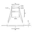
- FIG. 2 is a front view showing the illumination device of FIG.
- FIG. 3 is a side view showing the illumination device of FIG.
- FIG. 1 is a perspective view schematically showing the overall configuration of the lighting device 10.
- the illumination device 10 is a device that illuminates the illuminated area Z.
- the illuminated area Z is an elongated area having a longitudinal direction dl.
- the illuminated area Z has, for example, a ratio of the length in the longitudinal direction dl to the length in the short direction dw of 10 or more, and further, the illuminated area Z in which the ratio is 100 or more, typically a line shape It can be set as the to-be-illuminated area Z.
- Such a lighting device can be applied to vehicles such as automobiles and ships. In a vehicle, it is necessary to illuminate an area that extends forward in the direction of travel. In particular, it is preferable that a headlight of an automatic person traveling at a high speed, a so-called headlamp, brightly illuminates the road surface from the vicinity of the front of the automobile to the distance of the front.
- the illumination device 10 includes a light source device 15 that projects light and a diffractive optical element 40 that diffracts the light from the light source device 15 and directs the light toward the illuminated region Z.
- the light source device 15 includes a laser light source 20 and a shaping optical system 30 that shapes light emitted from the laser light source 20.
- the light source device 15 has a plurality of laser light sources 20.
- Laser light projected from the laser light source has excellent straightness and is suitable as light for illuminating the illuminated area Z with high accuracy.
- the plurality of laser light sources 20 may be provided independently, or may be a light source module in which a plurality of laser light sources 20 are arranged side by side on a common substrate.
- the plurality of laser light sources 20 include a first laser light source 20a that oscillates light in a red light emission wavelength region, a second laser light source 20b that oscillates light in a green light emission wavelength region, and a blue light emission wavelength region. And a third laser light source 20c that oscillates light.
- the illuminated area Z with illumination light of a desired color by superimposing the three laser lights emitted from the plurality of laser light sources 20.
- the radiant flux [unit: W] of the laser light emitted from the plurality of laser light sources 20 the color of the illumination light can be adjusted.
- the present invention is not limited to the above example, and the light source device 15 may include two laser light sources 20 or four or more laser light sources 20 having different emission wavelength ranges. In order to increase the emission intensity, a plurality of laser light sources 20 may be provided for each emission wavelength region.
- the shaping optical system 30 shapes the laser light emitted from the laser light source 20.
- the shaping optical system 30 shapes the shape of the cross section perpendicular to the optical axis of the laser light and the three-dimensional shape of the laser light beam.
- the shaping optical system 30 shapes the laser light emitted from the laser light source 20 into a broadened parallel light beam.
- the shaping optical system 30 includes a lens 31 and a collimating lens 32 in the order along the optical path of the laser light.
- the lens 31 shapes the laser light emitted from the laser light source 20 into a divergent light beam.
- the collimating lens 32 reshapes the divergent light beam generated by the lens 31 into a parallel light beam.
- the light source device 15 includes a first shaping optical system 30a, a second shaping optical system 30b, and a third shaping optical system 30c corresponding to the first to third laser light sources 20a to 20c, respectively.
- the first shaping optical system 30a includes a first lens 31a and a first collimating lens 32a
- the second shaping optical system 30b includes a second lens 31b and a second collimating lens 32b, and a third shaping optical system 30c.
- the diffractive optical element 40 is an element that exerts a diffractive action on the light emitted from the light source device 15.
- the illustrated diffractive optical element 40 diffracts the light from the light source device 15 and directs it toward the illuminated region Z. Therefore, the illuminated area Z is illuminated by the diffracted light from the diffractive optical element 40.
- the illumination device 10 has a plurality of diffractive optical elements 40. More specifically, the illumination device 10 includes a first diffractive optical element 40a, a second diffractive optical element 40b, and a third diffractive optical element 40c. Each diffractive optical element 40a, 40b, 40c is provided corresponding to each of the laser light sources 20a, 20b, 20c that oscillate laser light. According to this example, even when the laser light sources 20a, 20b, and 20c oscillate laser beams having different wavelength ranges, the diffractive optical elements 40a, 40b, and 40c have different wavelength ranges generated by the corresponding laser beams. It becomes possible to diffract laser light with high efficiency.
- the light emitted from each of the plurality of laser light sources 20a, 20b, and 20c is diffracted by the diffractive optical elements 40a, 40b, and 40c corresponding to the laser light sources, and then illuminates at least a partially overlapping region.
- light emitted from each of the plurality of laser light sources 20a, 20b, and 20c is diffracted by the diffractive optical elements 40a, 40b, and 40c corresponding to the laser light sources, and then the same illuminated region Z Illuminate. More precisely, the diffracted light diffracted by each diffractive optical element 40a, 40b, 40c illuminates only the entire illuminated area Z. Diffracted light from each of the diffractive optical elements 40a, 40b, and 40c illuminates only the entire illuminated area Z over the entire area, thereby effecting uneven brightness and uneven colors within the illuminated area Z. Can be inconspicuous.
- the plurality of diffractive optical elements 40 are arranged in a first direction da that is perpendicular to the longitudinal direction dl of the illuminated region Z.
- the first direction da in which the plurality of diffractive optical elements 40 are arranged is parallel to the normal direction nd to the surface pl as a flat surface on which the illuminated region Z is located.
- the first direction da in which the plurality of diffractive optical elements 40 are arranged is a vertical direction perpendicular to the horizontal direction. That is, in the illustrated example, the diffracted light from the plurality of diffractive optical elements 40 arranged vertically above the ground and the water surface illuminates the horizontal plane pl such as the ground and the water surface, and the horizontal plane pl An illuminated area Z is formed.
- the plurality of diffractive optical elements 40 are shifted in the vertical direction.
- the illuminated area Z can be considered as the illuminated area of the near field illuminated by the diffractive optical element 40.
- This illuminated area Z can be expressed not only by the actual illuminated area (illumination range) but also by a diffusion angle range in an angular space after setting a certain coordinate axis, as will be described later.
- each diffractive optical element 40 is configured as a hologram recording medium on which an interference fringe pattern is recorded.
- the traveling direction of the light diffracted by each diffractive optical element 40 in other words, the traveling direction of the light diffused by each diffractive optical element 40 can be controlled.
- Each diffractive optical element 40 can be produced using, for example, scattered light from a real scattering plate as object light. More specifically, when the hologram photosensitive material that is the base of the diffractive optical element 40 is irradiated with reference light and object light made of coherent light having coherence with each other, interference fringes due to interference of these lights are generated in the hologram photosensitive material. Thus, the diffractive optical element 40 is manufactured.
- reference light laser light which is coherent light is used, and as object light, for example, scattered light from an isotropic scattering plate available at low cost is used.
- the object light used in manufacturing the diffractive optical element 40 A reproduced image of the scattering plate is generated at the position of the original scattering plate. If the scattering plate that is the source of the object light used when producing the diffractive optical element 40 has a uniform surface scattering, the reproduced image of the scattering plate obtained by the diffractive optical element 40 will also be a uniform surface illumination.
- the region where the reproduced image of the scattering plate is generated can be the illuminated region Z.
- each diffractive optical element 40 is reproduced by the planned wavelength and incident direction of the reproduction illumination light, instead of using the actual object light and reference light. It is possible to design using a computer based on the shape and position of the power image.
- the diffractive optical element 40 thus obtained is also called a computer-generated hologram (CGH).
- CGH computer-generated hologram
- the illumination device 10 is used to illuminate an illuminated area Z having a certain size on the ground or the water surface, it is difficult to generate object light, and a computer-generated hologram is used as a diffractive optical element. It is preferable to use 40.
- a Fourier transform hologram having the same diffusion angle characteristic at each point on each diffractive optical element 40 may be formed by computer synthesis. Furthermore, an optical member such as a lens may be provided on the downstream side of the diffractive optical element 40 so that the diffracted light is adjusted to enter the entire illuminated area Z.
- a volume hologram recording medium using a photopolymer may be used, or a volume hologram recording medium of a type for recording using a photosensitive medium containing a silver salt material may be used.
- a relief type (emboss type) hologram recording medium may be used.
- the diffractive optical element 40 may be a transmissive type or a reflective type.
- the laser light emitted from each laser light source 20 first enters the corresponding shaping optical system 30.
- the shaping optical system 30 expands the laser light emitted from the laser light source 20.
- the shaping optical system 30 shapes the laser light so that the area occupied by the light spreads in the cross section orthogonal to the optical axis.
- the shaping optical system 30 includes a first shaping optical system 30a, a second shaping optical system 30b, and a third shaping optical system 30c that are separately provided corresponding to the laser light sources 20a, 20b, and 20c. Contains.
- Each shaping optical system 30 includes a lens 31 and a collimating lens 32. As shown in FIG. 1, the lens 31 of the shaping optical system 30 diverges the laser light emitted from the laser light source 20 and converts it into a divergent light beam. The collimating lens 32 of the shaping optical system 30 collimates the divergent light beam into a parallel light beam.
- the laser light shaped by the shaping optical system 30 is then directed to the diffractive optical element 40.
- the diffractive optical element 40 includes a first diffractive optical element 40a, a second diffractive optical element 40b, and a third diffractive optical element 40c that are separately provided corresponding to the laser light sources 20a, 20b, and 20c.
- Each diffractive optical element 40 records interference fringes corresponding to the center wavelength of laser light emitted from the corresponding laser light source 20, and diffracts laser light incident from a certain direction in a desired direction with high efficiency. Can do.
- each diffractive optical element 40 is diffused over the entire illuminated area Z located on a horizontal plane pl such as the ground or water surface.
- the illuminated area Z is formed by superimposing the laser light emitted from the first laser light source 20a, the laser light emitted from the second laser light source 20b, and the laser light emitted from the third laser light source 20c.
- the illuminated area Z can be illuminated with a color that cannot be reproduced only with the laser light emitted from the laser light source.
- the illumination colors are the radiant flux of laser light emitted from the first laser light source 20a, the radiant flux of laser light emitted from the second laser light source 20b, and the radiant flux of laser light emitted from the third laser light source 20c.
- the desired color can be obtained by adjusting the radiant flux of the emitted laser light by adjusting the output of each laser light source.
- the illuminating device 10 described here illuminates the illuminated area Z by adjusting the optical path of the laser light emitted from the laser light source 20 with the diffractive optical element 40.
- One advantage of using the diffractive optical element 40 is that the light energy density of light from the light source device 15, for example, laser light, can be reduced by diffusion.
- Another advantage is that the diffractive optical element 40 can be used as a directional surface light source. That is, when the laser light is directly viewed from the illuminated area Z with the human eye, it becomes a surface light source having the size of the diffractive optical element 40 instead of a point light source.
- the diffractive optical element 40 the laser beam having the same radiant flux is converted into illumination by a light source that emits from a wider light emitting surface, and the same illuminance distribution as compared with illumination by a point light source (lamp light source)
- the luminance at each position on the light source surface for achieving the above, that is, the power density can be reduced.
- the diffractive optical element 40 it is possible to contribute to improving the safety of laser light when the laser light source 20 is used as the light source.
- the area of the diffractive optical element 40 When the area of the diffractive optical element 40 is increased, a laser light incident area from the light source device 15, that is, a spot area can be widened.
- the laser light incident on the diffractive optical element 40 is diffracted by the diffractive optical element 40 and is emitted from the entire incident area on the diffractive optical element 40 toward the illuminated area Z. Therefore, the power density at each position on the diffractive optical element 40 can be reduced by increasing the areas of the incident surface and the exit surface of the diffractive optical element 40.
- the illumination device 10 when the area of the diffractive optical element 40 is increased, the illumination device 10 is increased in size.
- the problem of increasing the size of the illumination device becomes more serious in the above-described illumination device 10 that performs illumination with a specific color by additive color mixing using light in a plurality of wavelength ranges.
- a contrivance is made to achieve both a reduction in power density, which can be said to be in a trade-off relationship, and a reduction in size of the lighting device 10. That is, in the present embodiment, the area of the diffractive optical element 40 corresponding to the laser light source 20 is changed in accordance with the size of the radiant flux of the laser light emitted from the laser light source 20, thereby reducing the power density and the illumination device. It is aiming for compatibility with 10 miniaturization. A specific configuration will be described below.
- laser beam radiant flux here does not mean the maximum radiant flux that can be emitted by the laser light source.
- the “radiant flux of laser light” here does not mean the ability of the laser light source.
- the “radiant flux of laser light” means the radiant flux of laser light actually emitted from a laser light source whose output is adjusted according to the illumination application.
- the area of the diffractive optical element corresponding to the laser light source that emits the laser beam that has the minimum radiant flux among the laser beams emitted from the plurality of laser light sources 20 included in the illumination device 10 is the largest radiant flux.
- the area of the diffractive optical element corresponding to the laser light source that emits the laser light becomes smaller.
- the radiant flux of the laser light in the red wavelength range emitted from the first laser light source 20a is the largest, and the radiant flux of the laser light in the blue wavelength range emitted from the third laser light source 20c. Is the smallest.
- the first and second laser light sources oscillate with the maximum radiant flux in the areas of the entrance and exit surfaces of the third diffractive optical element 40c corresponding to the third laser light source 20c that oscillates the laser beam with the minimum radiant flux.
- the area is smaller than the area of the incident surface and the exit surface of the first diffractive optical element 40a corresponding to the laser light source 20a.
- the power density can be reduced accordingly. Accordingly, in consideration of the size of the radiant flux of the laser light source 20, the size of the exit surface of the diffractive optical element 40 and the size of the entrance surface that is usually the same region as the exit surface are determined. Safety can be imparted. On the other hand, when the radiant flux of the laser light emitted from the third laser light source 20c is smaller than the radiant flux of the laser light emitted from the first laser light source 20a, the power density at the position on the diffractive optical element is reduced.
- the apparatus 10 can be reduced in size.
- the minimum radiant flux of the laser light emitted from the third laser light source 20c is W min [W]
- the maximum radiant flux of the laser light emitted from the first laser light source 20a is W max [W].
- the area A min [mm 2 ] of the third diffractive optical element 40c corresponding to the third laser light source 20c for emitting laser light having the minimum radiant flux and the laser light having the maximum radiant flux are emitted.
- the area A max [mm 2 ] of the first diffractive optical element 40a corresponding to the first laser light source 20a satisfies the following relationship.
- the entire area of the first diffractive optical element 40a is effectively utilized, that is, the laser light is spread over the entire incident surface of the first diffractive optical element 40a and is incident with a uniform intensity.
- the magnitude of the power density at each position on the first diffractive optical element 40a is expressed using (W max / A max ) as an index. Therefore, the area A max of the first diffractive optical element 40a should be determined so that the value of the index (W max / A max ) is sufficient.
- the third diffractive optical element 40c has a smaller area than the first diffractive optical element 40a, but the power density at each position on the third diffractive optical element 40c is the same as that on the first diffractive optical element 40a. It is preferable to set it below the power density at each position.
- the magnitude of the power density at each position on the third diffractive optical element 40c on which the laser beam having the minimum radiant flux is incident is represented by (W min / A min ) as an index.
- the power density can be less than or equal to the power density at each position on the first diffractive optical element 40a. That is, when the above-described conditions are satisfied, the area of the first diffractive optical element 40a corresponding to the first laser light source 20a having the largest radiant flux with a relatively large area is set to the minimum necessary size, At the same time, it is possible to sufficiently reduce the power density in the third diffractive optical element 40c corresponding to the third laser light source 20c having the smallest radiant flux that is relatively miniaturized.
- the area of the diffractive optical element 40 corresponding to one arbitrarily selected laser light source 20 is another laser light source 20 having a larger radiant flux than the one laser light source 20. Or less than the area of the diffractive optical element 40 corresponding to. That is, as the radiant flux of the laser light source 20 decreases, the area of the corresponding diffractive optical element 40 decreases. In other words, as the radiant flux of the laser light source 20 increases, the area of the corresponding diffractive optical element 40 increases.
- the radiant flux of the laser light emitted from the second laser light source 20b is smaller than the radiant flux of the laser light emitted from the first laser light source 20a, and the radiation of the laser light emitted from the third laser light source 20c. It is larger than the bundle. That is, the radiant flux of the laser light decreases in the order of the first laser light source 20a, the second laser light source 20b, and the third laser light source 20c. As shown in FIGS. 2 and 3, in the illustrated example, the area decreases in the order of the first diffractive optical element 40 a, the second diffractive optical element 40 b, and the third diffractive optical element 40 c. According to such an illuminating device 10, the area of the diffractive optical element 40 can be effectively reduced at the same time while sufficiently reducing the power density at each position on each diffractive optical element 40.
- the radiant flux W a of the laser light emitted from the first laser light source 20a, the radiant flux W b of the laser light emitted from the second laser light source 20b, and the laser light emitted from the third laser light source 20c it is preferable that the radiant flux W c , the area A a of the first diffractive optical element 40 a, the area A b of the second diffractive optical element 40 b, and the area Ac of the third diffractive optical element 40 c satisfy the following relationship.
- radiant flux W c of the exit laser beam is 7: 4: has a two relationships.
- the area ratio of the first diffractive optical element 40a, the second diffractive optical element 40b, and the third diffractive optical element 40c is 7: 4: 2. As shown in FIG.
- the first diffractive optical element 40a, the second diffractive optical element 40b, and the third diffractive optical element 40c have the same length in the second direction db parallel to the width direction dw of the illuminated area Z.
- the first diffractive optical element 40a, the second diffractive optical element 40b, and the third diffractive optical element 40c have a length along the first direction da of 7: 4: 2. Oil. According to such an illuminating device 10, the power density can be made uniform among the diffractive optical elements 40. Therefore, by setting the power density to a sufficient value, the area of the plurality of diffractive optical elements 40 included in the illumination device 10 can be reduced.
- the illumination device 10 includes a plurality of laser light sources 20 that emit laser beams having different radiant fluxes, and a diffractive optical element provided corresponding to each of the plurality of laser light sources. 40.
- the area of the diffractive optical element 40 corresponding to the laser light source 20 that emits the laser beam having the minimum radiant flux is the area of the diffractive optical element 40 corresponding to the laser light source 20 that emits the laser beam having the maximum radiant flux. Is smaller than. That is, in the illumination device 10, the area of the corresponding diffractive optical element 40 is changed according to the size of the radiant flux of the laser light emitted from the laser light source 20.
- the power density at each position of each diffractive optical element 40 can be effectively reduced, and the area of the diffractive optical element 40 corresponding to the laser light source 20 that emits laser light having a low radiant flux is unnecessary. It is possible to effectively avoid the increase. As a result, it is possible to effectively downsize the lighting device 10 while ensuring safety.
- the illumination device 10 according to the present embodiment is particularly useful when the laser light source 20 in a plurality of wavelength ranges is included in this way.
- the laser light source 20 that emits the laser beam having the minimum radiant flux is supported.
- the area A min [mm 2 ] of the diffractive optical element 40 and the area A max [mm 2 ] of the diffractive optical element 40 corresponding to the laser light source 20 that emits the laser beam having the maximum radiant flux are as follows: It comes to satisfy.
- the power density at each position of the diffractive optical element 40 with a reduced area corresponding to the laser light source 20 that emits the laser beam with the minimum radiant flux is set to the laser beam with the maximum radiant flux.
- the power density at each position of the diffractive optical element 40 having a large area corresponding to the laser light source 20 that emits the light can be reduced to a level below.
- the power density at each position of the diffractive optical element 40 with a reduced area can be sufficiently reduced, which makes it possible to more effectively downsize the illumination device 10 while ensuring safety.
- the area of the diffractive optical element 40 corresponding to one arbitrarily selected laser light source 20 is a laser beam that has a larger radiant flux than the laser light emitted by the one laser light source 20.
- the area is equal to or smaller than the area of the diffractive optical element 40 corresponding to another laser light source 20 that emits light.
- the size of the diffractive optical element 40 corresponding to each laser light source 20 changes sequentially according to the size of the radiant flux of the laser light emitted from the laser light source 20. Therefore, the power density can be made uniform to some extent between the diffractive optical elements 40. As a result, the area of the diffractive optical element 40 can be minimized.
- the illumination device 10 further includes a shaping optical system 30 that magnifies and guides the laser light emitted from the plurality of laser light sources 20 to the diffractive optical element 40.
- the illumination device 10 the light emitted from the laser light source 20 is incident on the diffractive optical element 40 after being enlarged. Therefore, the power density at each position of the diffractive optical element 40 can be effectively reduced, and safety can be improved.
- any one or more elements of the shaping optical system 30 or the lens 31 and the collimating lens 32 included in the shaping optical system 30 may be shared among the plurality of laser light sources 20.
- the illuminating device 10 may illuminate a region having a predetermined contour, and thus function as a device that displays the predetermined contour.
- An example of the predetermined contour is an arrow.
Landscapes
- Physics & Mathematics (AREA)
- Engineering & Computer Science (AREA)
- General Engineering & Computer Science (AREA)
- General Physics & Mathematics (AREA)
- Optics & Photonics (AREA)
- Spectroscopy & Molecular Physics (AREA)
- Non-Portable Lighting Devices Or Systems Thereof (AREA)
- Lighting Device Outwards From Vehicle And Optical Signal (AREA)
Abstract
Un dispositif d'éclairage (10) comprend : de multiples sources de lumière laser (20) ayant différents flux de rayonnement; et des éléments optiques de diffraction (40) disposés de façon à correspondre respectivement aux multiples sources de lumière laser. La surface de l'élément optique de diffraction correspondant à la source de lumière laser ayant le plus petit flux de rayonnement est plus petite que la surface de l'élément optique de diffraction correspondant à la source de lumière laser ayant le plus grand flux de rayonnement.
Priority Applications (5)
| Application Number | Priority Date | Filing Date | Title |
|---|---|---|---|
| US16/472,963 US11193640B2 (en) | 2017-01-05 | 2017-12-28 | Illumination device |
| CN202111080724.8A CN113719802B (zh) | 2017-01-05 | 2017-12-28 | 照明装置 |
| EP17890379.5A EP3567304A4 (fr) | 2017-01-05 | 2017-12-28 | Dispositif d'éclairage |
| CN201780079510.4A CN110114612B (zh) | 2017-01-05 | 2017-12-28 | 照明装置 |
| US17/448,359 US11359785B2 (en) | 2017-01-05 | 2021-09-22 | Illumination device |
Applications Claiming Priority (2)
| Application Number | Priority Date | Filing Date | Title |
|---|---|---|---|
| JP2017000671A JP6761600B2 (ja) | 2017-01-05 | 2017-01-05 | 照明装置 |
| JP2017-000671 | 2017-01-05 |
Related Child Applications (2)
| Application Number | Title | Priority Date | Filing Date |
|---|---|---|---|
| US16/472,963 A-371-Of-International US11193640B2 (en) | 2017-01-05 | 2017-12-28 | Illumination device |
| US17/448,359 Continuation US11359785B2 (en) | 2017-01-05 | 2021-09-22 | Illumination device |
Publications (1)
| Publication Number | Publication Date |
|---|---|
| WO2018128162A1 true WO2018128162A1 (fr) | 2018-07-12 |
Family
ID=62791047
Family Applications (1)
| Application Number | Title | Priority Date | Filing Date |
|---|---|---|---|
| PCT/JP2017/047233 WO2018128162A1 (fr) | 2017-01-05 | 2017-12-28 | Dispositif d'éclairage |
Country Status (5)
| Country | Link |
|---|---|
| US (2) | US11193640B2 (fr) |
| EP (1) | EP3567304A4 (fr) |
| JP (1) | JP6761600B2 (fr) |
| CN (2) | CN113719802B (fr) |
| WO (1) | WO2018128162A1 (fr) |
Families Citing this family (3)
| Publication number | Priority date | Publication date | Assignee | Title |
|---|---|---|---|---|
| JP7131153B2 (ja) * | 2018-07-13 | 2022-09-06 | 大日本印刷株式会社 | 照明装置および照明装置ユニット |
| CN113606550A (zh) * | 2018-09-26 | 2021-11-05 | 株式会社小糸制作所 | 车辆用灯具 |
| DE102021116099A1 (de) * | 2020-11-02 | 2022-05-05 | Olsa S.P.A. | Optische vorrichtung für kraftfahrzeuge, lampe für kraftfahrzeuge und umgebungslicht |
Citations (5)
| Publication number | Priority date | Publication date | Assignee | Title |
|---|---|---|---|---|
| JP2008268878A (ja) * | 2007-03-27 | 2008-11-06 | Seiko Epson Corp | ホログラム素子、照明装置、プロジェクタ、及びホログラム素子の製造方法 |
| JP2015132707A (ja) | 2014-01-14 | 2015-07-23 | 大日本印刷株式会社 | 表示装置及び表示装置が搭載された車両 |
| JP2016024929A (ja) * | 2014-07-18 | 2016-02-08 | スタンレー電気株式会社 | 車両用灯具 |
| WO2016072503A1 (fr) * | 2014-11-07 | 2016-05-12 | 大日本印刷株式会社 | Dispositif d'éclairage |
| WO2016208594A1 (fr) * | 2015-06-22 | 2016-12-29 | 大日本印刷株式会社 | Dispositif d'éclairage |
Family Cites Families (22)
| Publication number | Priority date | Publication date | Assignee | Title |
|---|---|---|---|---|
| JP3987350B2 (ja) * | 2001-11-16 | 2007-10-10 | 株式会社リコー | レーザ照明光学系及びそれを用いた露光装置、レーザ加工装置、投射装置 |
| US6993059B2 (en) * | 2003-06-11 | 2006-01-31 | Coherent, Inc. | Apparatus for reducing spacing of beams delivered by stacked diode-laser bars |
| KR20090035514A (ko) * | 2006-07-14 | 2009-04-09 | 코니카 미놀타 옵토 인코포레이티드 | 광 픽업 장치, 대물 광학 소자 및 광 정보 기록 재생 장치 |
| CN101123100B (zh) * | 2006-07-14 | 2011-05-11 | 柯尼卡美能达精密光学株式会社 | 光拾取装置、对物光学元件和光信息记录重放装置 |
| US7950809B2 (en) | 2007-03-27 | 2011-05-31 | Seiko Epson Corporation | Hologram element, illumination device, projector, and method of manufacturing hologram element |
| JP5168526B2 (ja) * | 2011-05-10 | 2013-03-21 | 大日本印刷株式会社 | 投射型映像表示装置 |
| JP2013219560A (ja) * | 2012-04-09 | 2013-10-24 | Sony Corp | 撮像装置、撮像方法及びカメラシステム |
| JP6285650B2 (ja) * | 2013-07-03 | 2018-02-28 | 浜松ホトニクス株式会社 | レーザ装置 |
| AT514967B1 (de) * | 2013-10-25 | 2015-08-15 | Zizala Lichtsysteme Gmbh | Mikroprojektions-Lichtmodul für einen Kraftfahrzeugscheinwerfer |
| JP6411771B2 (ja) * | 2014-04-16 | 2018-10-24 | 株式会社小糸製作所 | 車両用灯具 |
| WO2016072484A1 (fr) * | 2014-11-07 | 2016-05-12 | 大日本印刷株式会社 | Dispositif optique, véhicule sur lequel le dispositif optique est monté, et éclairage dispositif |
| JP6579302B2 (ja) * | 2014-11-07 | 2019-09-25 | 大日本印刷株式会社 | 光学装置及び光学装置が搭載された車両 |
| WO2016072505A1 (fr) * | 2014-11-07 | 2016-05-12 | 大日本印刷株式会社 | Dispositif d'éclairage |
| JP6555462B2 (ja) * | 2014-12-05 | 2019-08-07 | 大日本印刷株式会社 | 光学装置 |
| DE102015001693A1 (de) * | 2015-02-10 | 2016-08-11 | Audi Ag | Beleuchtungseinrichtung für ein Kraftfahrzeug |
| JP6504886B2 (ja) * | 2015-04-03 | 2019-04-24 | 株式会社小糸製作所 | 車両用灯具 |
| AT516743B1 (de) * | 2015-04-16 | 2016-08-15 | Zizala Lichtsysteme Gmbh | Beleuchtungsvorrichtung für ein Kraftfahrzeug |
| DE102015106312A1 (de) * | 2015-04-24 | 2016-10-27 | Osram Gmbh | Beleuchtungsvorrichtung mit Halbleiter-Primärlichtquellen und mindestens einem Leuchtstoffkörper |
| EP3312499B1 (fr) * | 2015-06-22 | 2023-11-29 | Dai Nippon Printing Co., Ltd. | Dispositif d'éclairage |
| WO2017005604A1 (fr) * | 2015-07-07 | 2017-01-12 | Koninklijke Philips N.V. | Appareil électroluminescent |
| CN108367389B (zh) * | 2015-11-23 | 2020-07-28 | 恩耐公司 | 激光加工方法和装置 |
| CN108255004B (zh) * | 2016-12-28 | 2021-03-30 | 佳能株式会社 | 光源装置和图像投影装置 |
-
2017
- 2017-01-05 JP JP2017000671A patent/JP6761600B2/ja active Active
- 2017-12-28 CN CN202111080724.8A patent/CN113719802B/zh active Active
- 2017-12-28 WO PCT/JP2017/047233 patent/WO2018128162A1/fr unknown
- 2017-12-28 CN CN201780079510.4A patent/CN110114612B/zh active Active
- 2017-12-28 US US16/472,963 patent/US11193640B2/en active Active
- 2017-12-28 EP EP17890379.5A patent/EP3567304A4/fr active Pending
-
2021
- 2021-09-22 US US17/448,359 patent/US11359785B2/en active Active
Patent Citations (5)
| Publication number | Priority date | Publication date | Assignee | Title |
|---|---|---|---|---|
| JP2008268878A (ja) * | 2007-03-27 | 2008-11-06 | Seiko Epson Corp | ホログラム素子、照明装置、プロジェクタ、及びホログラム素子の製造方法 |
| JP2015132707A (ja) | 2014-01-14 | 2015-07-23 | 大日本印刷株式会社 | 表示装置及び表示装置が搭載された車両 |
| JP2016024929A (ja) * | 2014-07-18 | 2016-02-08 | スタンレー電気株式会社 | 車両用灯具 |
| WO2016072503A1 (fr) * | 2014-11-07 | 2016-05-12 | 大日本印刷株式会社 | Dispositif d'éclairage |
| WO2016208594A1 (fr) * | 2015-06-22 | 2016-12-29 | 大日本印刷株式会社 | Dispositif d'éclairage |
Non-Patent Citations (1)
| Title |
|---|
| See also references of EP3567304A4 |
Also Published As
| Publication number | Publication date |
|---|---|
| CN113719802A (zh) | 2021-11-30 |
| CN113719802B (zh) | 2024-03-12 |
| CN110114612B (zh) | 2021-10-12 |
| EP3567304A1 (fr) | 2019-11-13 |
| US20220003373A1 (en) | 2022-01-06 |
| US20190360654A1 (en) | 2019-11-28 |
| EP3567304A4 (fr) | 2020-08-26 |
| JP2018110081A (ja) | 2018-07-12 |
| US11359785B2 (en) | 2022-06-14 |
| US11193640B2 (en) | 2021-12-07 |
| CN110114612A (zh) | 2019-08-09 |
| JP6761600B2 (ja) | 2020-09-30 |
Similar Documents
| Publication | Publication Date | Title |
|---|---|---|
| US11359785B2 (en) | Illumination device | |
| CN110177711B (zh) | 照明装置 | |
| JP6803009B2 (ja) | 照明装置 | |
| JP7022394B2 (ja) | 照明装置 | |
| WO2018216609A1 (fr) | Dispositif d'éclairage | |
| WO2017145972A1 (fr) | Dispositif d'éclairage | |
| JP6569958B2 (ja) | 照明装置 | |
| JP6936978B2 (ja) | 照明装置、照明装置の製造方法、照明方法 | |
| JP6850424B2 (ja) | 光源装置及び照明装置 | |
| JP7131153B2 (ja) | 照明装置および照明装置ユニット | |
| JP6909429B2 (ja) | 照明装置 | |
| JP7249510B2 (ja) | 照明装置 | |
| JP7011787B2 (ja) | 照明装置 | |
| JP6146680B2 (ja) | 照明装置 | |
| JP2019053887A (ja) | 照明装置 | |
| JP6722411B2 (ja) | 照明装置 | |
| JP2019148711A (ja) | 回折光学素子の回折特性の設計方法および照明装置 | |
| JP2017084624A (ja) | 照明装置 |
Legal Events
| Date | Code | Title | Description |
|---|---|---|---|
| 121 | Ep: the epo has been informed by wipo that ep was designated in this application |
Ref document number: 17890379 Country of ref document: EP Kind code of ref document: A1 |
|
| NENP | Non-entry into the national phase |
Ref country code: DE |
|
| ENP | Entry into the national phase |
Ref document number: 2017890379 Country of ref document: EP Effective date: 20190805 |