WO2018216609A1 - Dispositif d'éclairage - Google Patents
Dispositif d'éclairage Download PDFInfo
- Publication number
- WO2018216609A1 WO2018216609A1 PCT/JP2018/019262 JP2018019262W WO2018216609A1 WO 2018216609 A1 WO2018216609 A1 WO 2018216609A1 JP 2018019262 W JP2018019262 W JP 2018019262W WO 2018216609 A1 WO2018216609 A1 WO 2018216609A1
- Authority
- WO
- WIPO (PCT)
- Prior art keywords
- light
- axis
- illumination
- scanning
- diffusing element
- Prior art date
Links
Images


Classifications
-
- F—MECHANICAL ENGINEERING; LIGHTING; HEATING; WEAPONS; BLASTING
- F21—LIGHTING
- F21S—NON-PORTABLE LIGHTING DEVICES; SYSTEMS THEREOF; VEHICLE LIGHTING DEVICES SPECIALLY ADAPTED FOR VEHICLE EXTERIORS
- F21S41/00—Illuminating devices specially adapted for vehicle exteriors, e.g. headlamps
- F21S41/10—Illuminating devices specially adapted for vehicle exteriors, e.g. headlamps characterised by the light source
- F21S41/14—Illuminating devices specially adapted for vehicle exteriors, e.g. headlamps characterised by the light source characterised by the type of light source
- F21S41/16—Laser light sources
-
- F—MECHANICAL ENGINEERING; LIGHTING; HEATING; WEAPONS; BLASTING
- F21—LIGHTING
- F21S—NON-PORTABLE LIGHTING DEVICES; SYSTEMS THEREOF; VEHICLE LIGHTING DEVICES SPECIALLY ADAPTED FOR VEHICLE EXTERIORS
- F21S41/00—Illuminating devices specially adapted for vehicle exteriors, e.g. headlamps
- F21S41/10—Illuminating devices specially adapted for vehicle exteriors, e.g. headlamps characterised by the light source
- F21S41/12—Illuminating devices specially adapted for vehicle exteriors, e.g. headlamps characterised by the light source characterised by the type of emitted light
- F21S41/125—Coloured light
-
- F—MECHANICAL ENGINEERING; LIGHTING; HEATING; WEAPONS; BLASTING
- F21—LIGHTING
- F21S—NON-PORTABLE LIGHTING DEVICES; SYSTEMS THEREOF; VEHICLE LIGHTING DEVICES SPECIALLY ADAPTED FOR VEHICLE EXTERIORS
- F21S41/00—Illuminating devices specially adapted for vehicle exteriors, e.g. headlamps
- F21S41/20—Illuminating devices specially adapted for vehicle exteriors, e.g. headlamps characterised by refractors, transparent cover plates, light guides or filters
- F21S41/285—Refractors, transparent cover plates, light guides or filters not provided in groups F21S41/24-F21S41/28
-
- F—MECHANICAL ENGINEERING; LIGHTING; HEATING; WEAPONS; BLASTING
- F21—LIGHTING
- F21S—NON-PORTABLE LIGHTING DEVICES; SYSTEMS THEREOF; VEHICLE LIGHTING DEVICES SPECIALLY ADAPTED FOR VEHICLE EXTERIORS
- F21S41/00—Illuminating devices specially adapted for vehicle exteriors, e.g. headlamps
- F21S41/40—Illuminating devices specially adapted for vehicle exteriors, e.g. headlamps characterised by screens, non-reflecting members, light-shielding members or fixed shades
-
- F—MECHANICAL ENGINEERING; LIGHTING; HEATING; WEAPONS; BLASTING
- F21—LIGHTING
- F21S—NON-PORTABLE LIGHTING DEVICES; SYSTEMS THEREOF; VEHICLE LIGHTING DEVICES SPECIALLY ADAPTED FOR VEHICLE EXTERIORS
- F21S41/00—Illuminating devices specially adapted for vehicle exteriors, e.g. headlamps
- F21S41/60—Illuminating devices specially adapted for vehicle exteriors, e.g. headlamps characterised by a variable light distribution
- F21S41/67—Illuminating devices specially adapted for vehicle exteriors, e.g. headlamps characterised by a variable light distribution by acting on reflectors
- F21S41/675—Illuminating devices specially adapted for vehicle exteriors, e.g. headlamps characterised by a variable light distribution by acting on reflectors by moving reflectors
-
- F—MECHANICAL ENGINEERING; LIGHTING; HEATING; WEAPONS; BLASTING
- F21—LIGHTING
- F21S—NON-PORTABLE LIGHTING DEVICES; SYSTEMS THEREOF; VEHICLE LIGHTING DEVICES SPECIALLY ADAPTED FOR VEHICLE EXTERIORS
- F21S45/00—Arrangements within vehicle lighting devices specially adapted for vehicle exteriors, for purposes other than emission or distribution of light
- F21S45/70—Prevention of harmful light leakage
-
- G—PHYSICS
- G02—OPTICS
- G02B—OPTICAL ELEMENTS, SYSTEMS OR APPARATUS
- G02B5/00—Optical elements other than lenses
- G02B5/18—Diffraction gratings
- G02B5/1861—Reflection gratings characterised by their structure, e.g. step profile, contours of substrate or grooves, pitch variations, materials
-
- G—PHYSICS
- G02—OPTICS
- G02B—OPTICAL ELEMENTS, SYSTEMS OR APPARATUS
- G02B5/00—Optical elements other than lenses
- G02B5/32—Holograms used as optical elements
-
- F—MECHANICAL ENGINEERING; LIGHTING; HEATING; WEAPONS; BLASTING
- F21—LIGHTING
- F21W—INDEXING SCHEME ASSOCIATED WITH SUBCLASSES F21K, F21L, F21S and F21V, RELATING TO USES OR APPLICATIONS OF LIGHTING DEVICES OR SYSTEMS
- F21W2102/00—Exterior vehicle lighting devices for illuminating purposes
- F21W2102/10—Arrangement or contour of the emitted light
- F21W2102/13—Arrangement or contour of the emitted light for high-beam region or low-beam region
- F21W2102/135—Arrangement or contour of the emitted light for high-beam region or low-beam region the light having cut-off lines, i.e. clear borderlines between emitted regions and dark regions
-
- G—PHYSICS
- G02—OPTICS
- G02B—OPTICAL ELEMENTS, SYSTEMS OR APPARATUS
- G02B5/00—Optical elements other than lenses
- G02B5/02—Diffusing elements; Afocal elements
Definitions
- an illumination pattern having a desired shape can be formed on the road surface. That is, when light is incident on the holographic optical element from a predetermined direction, the diffracted light is emitted in a direction corresponding to the recorded diffraction pattern, and the predetermined position of the illumination target surface is determined by the emitted diffracted light.
- the illumination pattern can be illuminated.
- JP 2012-146621 A Japanese Patent Laying-Open No. 2015-132707
- an object of the present invention is to provide an illumination device capable of forming a clear illumination area in which blur is suppressed on a surface to be illuminated while ensuring safety against coherent light.
- the illumination target surface is set on the XY plane
- the light emission surface of the light diffusing element is positioned on a plane parallel to the XZ plane
- the first diffusion axis is the X axis.
- the second diffusion axis is parallel to the Z axis
- the diffused light emitted from the light emitting surface of the light diffusing element is directed to the surface to be illuminated, and the cross section when the diffused light is cut along a plane perpendicular to the central axis is two parallel to the X axis.
- the light diffusing element performs anisotropic diffusion so that the rectangle has a long side and a short side of the other two sides.
- the light diffusing element is constituted by a diffractive optical element or a holographic optical element, Diffraction that causes diffracted light having an angular space distribution of a predetermined first-order diffracted light intensity to be emitted as diffused light to each part of the light diffusing element when incident light having a predetermined incident angle is given. Lattices or interference fringes are recorded, The displacement angle of the diffracted light with respect to the incident light at the predetermined incident point is expressed by a first direction displacement angle indicating displacement in the first diffusion axis direction and a second direction displacement angle indicating displacement in the second diffusion axis direction.
- the illumination target surface is set on the XY plane
- the light emission surface of the light diffusing element is positioned on a plane parallel to the XZ plane
- the first diffusion axis is the X axis.
- the second diffusion axis is parallel to the Z axis
- the angular space distribution of the first-order diffracted light intensity for each part of the light diffusing element is arranged on the distribution graph at a position having a predetermined ordinate value around the ordinate axis so that the diffused light is directed toward the illumination target surface. It is expressed by a diffracted light distribution region composed of a horizontally elongated rectangle.
- a seventh aspect of the present invention is the lighting device according to the fifth aspect described above,
- the illumination target surface is set on the XY plane.
- the light emitting surface of the light diffusing element is located on a plane parallel to the XZ ′ plane, the first diffusion axis is parallel to the X axis, and the second diffusion axis is parallel to the Z ′ axis,
- the angular space distribution of the first-order diffracted light intensity for each part of the light diffusing element is represented on the distribution graph by a diffracted light distribution area composed of a horizontally long rectangle arranged with the origin as the center.
- the light diffusing element is constituted by a diffractive optical element in which a diffraction grating in which a large number of grating lines parallel to the Z ′ axis are arranged at a plurality of pitches is recorded in a physical structure.
- a ninth aspect of the present invention is the lighting device according to the fifth to seventh aspects described above,
- the light diffusing element is constituted by a holographic optical element in which each part generates a reproduction image of a rectangular surface at a predetermined position.
- a tenth aspect of the present invention is the illumination device according to the fifth to seventh aspects described above,
- the light diffusing element is a holographic optical element having a plurality of element diffractive optical regions, and independent individual holograms are recorded in each of the plurality of element diffractive optical regions.
- the scanning beam When the scanning beam is received, it has a function of emitting diffused light that forms separate drawing spots at individual positions on the illumination target surface through the illumination optical system.
- An eleventh aspect of the present invention is the illumination device according to the ninth or tenth aspect described above,
- the light diffusing element is a holographic optical element in which CGH having interference fringes obtained by calculation by a computer is recorded in a physical structure.
- the illumination target surface is set on the XY plane
- the light emission surface of the light diffusing element is positioned on a plane parallel to the XZ plane
- the optical axis of the illumination optical system is It becomes parallel to the central axis of the diffused light emitted from a predetermined point on the light emission surface of the light diffusing element
- the first diffusion axis is parallel to the X axis
- the second diffusion axis is parallel to the Z axis.
- the illumination target surface is set on the XY plane.
- the light emitting surface of the light diffusing element is located on a plane parallel to the XZ ′ plane, the optical axis of the illumination optical system is orthogonal to the XZ ′ plane, the first diffusion axis is parallel to the X axis, and the second The diffusion axis is parallel to the Z 'axis,
- a virtual projection plane parallel to the XZ ′ plane is defined at the front position of the illumination optical system, a pair of diffused light from the light diffusing element is parallel to the X axis on the virtual projection plane at each scanning time point.
- a rectangular diffused light spot having a long side and a pair of short sides parallel to the Z ′ axis is formed.
- the illumination optical system is constituted by a collimating lens, and the light emitting surface of the light diffusing element is arranged at the front focal position of the collimating lens.
- a scanning member having a transmissive scanning body that emits light incident on the first surface from the second surface, and a scanning mechanism that rotates and scans the transmissive scanning body about two axes;
- a light beam from a light source is transmitted through the transmissive scanning body, and the transmitted light beam is directed to the light diffusing element as a scanning beam;
- the scanning control unit performs scanning control to change the incident point of the scanning beam to the light diffusing element in a two-dimensional manner.
- a mounting portion for mounting on the vehicle is further provided, the illumination target surface is set on the road surface, and the road surface can be illuminated from the vehicle.
- a coherent light beam is irradiated onto the light diffusing element, and a drawing spot is formed on the surface to be illuminated by the diffused light therefrom.
- a drawing spot is formed on the surface to be illuminated by the diffused light therefrom.
- the light beam is scanned, an illumination area having a desired shape is drawn by the moving drawing spot.
- the light diffusing element performs anisotropic diffusion, the spread of the diffused light is biased in one direction. For this reason, it is possible to form a clear illumination area in which blur is suppressed on the illumination target surface while ensuring safety against coherent light.
- FIG. 5 is a plan view showing a moving state of a diffused light spot G formed by diffused light L130 incident on the illumination optical system 140 when the scan shown in FIG. 4 is performed.
- FIG. 4 is a side view showing an example of an optical path through which diffused light L130 emitted from the light diffusing element 130 in the illumination device 100 shown in FIG. 3 reaches the illumination target surface S via the illumination optical system 140.
- FIG. 12 is a non-orthographic projection view showing a state in which each component shown in FIG. 11 is observed from a line-of-sight direction V. It is a top view which shows scanning area
- FIG. 6 is a diagram for explaining a reason why a blur is generated in a contour portion of a pattern when a pattern is formed by a drawing spot K.
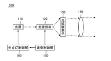
- It is a block diagram which shows the basic composition of the illuminating device 300 with a lighting control function which concerns on the modification of this invention.
- It is a perspective view (a part is block diagram) which shows the basic composition of the color illuminating device 400 which concerns on the modification of this invention.
- It is a top view (a part is block diagram) which shows the illuminating device 600 using many lenses concerning the modification of this invention.
- An illumination device is a device suitable for forming an illumination area having a predetermined shape on a predetermined illumination target surface, and particularly, an in-vehicle device that forms an illumination pattern having a desired shape on a road surface. Suitable for use in lighting equipment of the type. In such an application, the angle formed by the optical axis of the illumination light and the illumination target surface is very small, and thus the illumination pattern presented as the illumination area tends to be unclear. In the illumination device according to the present invention, it is possible to form a clear illumination pattern on the illumination target surface even in such an application. Therefore, in this ⁇ 1, as a typical application example of the present invention, features of an in-vehicle illumination device for forming a desired illumination pattern on a road surface will be briefly described.
- the figure shows an example in which an illumination area 20 having an arrow shape is formed on the road surface 10.
- the illumination area 20 is obtained by projecting illumination light from the vehicle-mounted illumination device onto the road surface 10, and moves forward as the vehicle travels.
- an area inside the illumination area 20 is illuminated, and an illumination pattern of an arrow figure is recognized as a bright area on the road surface 10 when viewed from a driver or a pedestrian.
- This arrow-shaped illumination pattern (illumination area 20) can be used as an indicator on the road surface for presenting some information (for example, the traveling direction of the vehicle) to the driver or pedestrian 30.
- the illumination area 20 is not limited to the arrow graphic, and the illumination area 20 composed of an arbitrary graphic pattern or an arbitrary character pattern can be formed by scanning a light beam to be described later.
- the feature of the illumination device according to the present invention is that an arbitrary illumination pattern can be formed on the illumination target surface. In general, it is easy to recognize the illumination area 20 formed on the road surface 10 at night. However, in the daytime, it is necessary to ensure sufficient illumination intensity so that the illumination area 20 is displayed with a certain degree of brightness. is there. As will be described later, the illumination device according to the present invention uses a coherent light source that emits coherent light such as laser light, so that sufficient illumination intensity can be ensured.
- coherent light such as laser light has a much higher radiation intensity than general light, which may damage the eyes of the observer.
- the surface to be illuminated is illuminated with diffused light, so that the light intensity per unit area of the illuminating light is weakened to a sufficiently safe level. For this reason, even if a pedestrian 30 or a driver of an oncoming vehicle looks directly at the light source side of the lighting device, strong coherent light does not enter the human eye and there is no possibility of damaging the human eye.
- the angle formed between the optical axis of the illumination light and the illumination target surface is extremely small, so that the illumination pattern formed as the illumination region 20 is unclear. It is easy to become. In particular, blur is generated in the outline of the illumination pattern formed on the road surface 10 (in the illustrated example, the tip of the arrow) and in front (in the illustrated example, the root of the arrow). It's easy to do.
- the lighting device according to the present invention also has a function to cope with such a problem.
- FIG. 2 is a side view showing an example in which an illumination area 20 (thick line portion) is formed on the road surface 10 by illumination from the vehicle-mounted illumination device 100.
- the vehicle (automobile) 40 is traveling on the road surface 10 from the left to the right in the figure.
- the Y axis is defined in the traveling direction of the vehicle 40 (right direction in the figure)
- the Z axis is defined in the direction orthogonal to the road surface 10 (upward direction in the figure).
- the X axis is not shown in FIG. 2, the X axis faces in the direction perpendicular to the paper surface.
- the illumination device 100 shown in FIG. 2 is a device different from a headlight of an automobile, but can be used as a headlight or can be incorporated into a headlight.
- the illumination device 100 can be used as various illumination lamps such as a taillight and a searchlight of an automobile, and can be incorporated into these various illumination lamps or used in a bumper section or the like. It can be installed and used.
- the in-vehicle illumination device 100 shown in FIG. 2 has a function of forming an arbitrarily shaped illumination region 20 on the road surface 10 located on the XY plane.
- the driver usually looks at the direction of travel of the road surface 10. Therefore, in order to bring the illumination area 20 into the center of the driver's field of view, it is necessary to form the illumination area 20 at a considerable distance on the road surface 10.
- FIG. 2 shows an example in which an illumination region 20 (thick line portion) having a longitudinal direction of 10 m is formed at a position 50 m ahead of the vehicle 40.
- the angle ⁇ (the irradiation angle with respect to the illumination target surface) formed by the optical axis C and the road surface 10 is 0.7 °. It will be about.
- the magnitude of ⁇ is depicted as being deformed, but in reality, the angle formed by the optical axis C and the road surface 10 is extremely small.
- the vehicle-mounted illumination device 100 has a feature that the irradiation angle ⁇ of light with respect to the illumination target surface is extremely small, unlike a general projector.
- a general projector since the reference of the irradiation angle ⁇ is 90 °, a usage form in which the irradiation angle ⁇ is about 0.7 ° as in the above example is unexpected. Therefore, if a lighting mechanism used in a general projector is directly converted into an in-vehicle lighting device, it becomes difficult to obtain a clear projection image on a projection surface (illumination target surface).
- the coherent light beam is anisotropically diffused, a drawing spot is formed on the surface to be illuminated by the diffused light, and the drawing is performed by scanning the light beam.
- the spot is moved to form an illumination area having a desired illumination pattern.
- anisotropic diffusion is effective in suppressing blurring of the outline of the illumination area, and is effective in ensuring safety against coherent light.
- Such a vehicle-mounted illumination device 100 is provided with an attachment portion for attachment to the vehicle 40, and is set on the road surface 10 from the vehicle 40 by being attached to the front, rear, side, etc. of the vehicle 40. It is possible to illuminate the illuminated surface to be illuminated.
- the illumination device according to the present invention is not necessarily limited to the vehicle-mounted illumination device.
- the lighting device according to the present invention can be used by being mounted on various vehicles including ships, airplanes, trains and the like as well as vehicles such as automobiles, motorcycles and bicycles.
- the illuminating device according to the present invention can be used not only for an application mounted on such a vehicle but also for an application for presenting various information by being attached to various structures.
- the lighting device according to the present invention is attached to a road surface, a structure installed near the road surface, a building, or the like, it can also be used for the purpose of presenting various guide signs and guidance signs.
- the illumination target surface on which the illumination area is formed by the illumination device according to the present invention does not necessarily have to be a flat surface, and a curved surface may be used as the illumination target surface depending on the application.
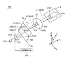
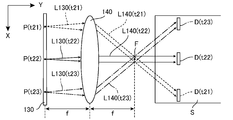
- FIG. 3 is a perspective view (partially a block diagram) showing the basic configuration of the illumination device 100 according to the basic embodiment of the present invention.
- This lighting device 100 is a vehicle-mounted device described in ⁇ 1, and is attached to the front portion of the vehicle 40 as shown in FIG. 2, and forms an illumination region 20 by illuminating the road surface 10 that is the illumination target surface. It has a function to do.
- the illumination device 100 includes a light source 110, a scanning member 120, a light diffusing element 130, an illumination optical system 140, and a scanning control unit 150 (shown in a block diagram), and a predetermined illumination target surface S. Illumination is performed by forming an illumination area LA having a predetermined shape.
- the illumination target surface S is a road surface in front of the vehicle, and FIG. 3 shows a state in which an illumination area LA composed of an illumination pattern of an arrow figure is formed.
- the outline of the illumination target surface S is indicated by a rectangle, but the illumination target surface S is a conceptual surface and does not necessarily have to be a rectangular surface. Further, as described above, the illumination target surface S may be a curved surface.
- an XYZ three-dimensional orthogonal coordinate system having the X axis, the Y axis, and the Z axis in each direction shown in the figure is defined, and the arrangement of each component will be described with reference to this coordinate system.
- the directions of the X, Y, and Z axes in the coordinate system shown in FIG. 3 are the same as the directions of the coordinate axes shown in FIGS. 1 and 2, the Y axis is the traveling direction of the vehicle 40, and the X axis is orthogonal to this.
- the horizontal direction and the Z axis are in the vertical direction.
- the X axis and the Y axis are axes on the horizontal plane, and the illumination target surface S (road surface 10) corresponds to the XY plane.
- the Z ′ axis is an axis obtained by rotating the Z axis by a predetermined inclination angle ⁇ with the X axis as a rotation axis (rotating clockwise when viewed in the negative direction of the X axis). is there. Therefore, the XZ ′ plane is a plane inclined by rotating the XZ plane by the tilt angle ⁇ with the X axis as the rotation axis. As will be described later, the light diffusing element 130 and the illumination optical system 140 are arranged on a plane parallel to the XZ ′ plane.
- the light source 110 is a component that emits a coherent light beam L110, and in general, a laser light source that emits laser light may be used. There are various types of laser light sources, but any type of laser light source may be used. In the embodiment shown here, a semiconductor laser that emits a circular light beam L110 having a cross section of about several tens of micrometers in diameter is used.
- the scanning member 120 is a component that scans the light beam L110 from the light source 110.
- FIG. 3 shows an example in which the scanning member 120 performs one-dimensional scanning with the light beam L110.
- the optical paths of the scanned light beam L120 (hereinafter referred to as scanning beam L120) are the scanning beam L120 (t1), the scanning beam L120 (t2), and the scanning beam L120, respectively. Shown as scanning beam L120 (t3).
- the light beam L110 is irradiated to the incident point P (t1) of the light diffusing element 130 as the scanning beam L120 (t1), and at the scanning time t2, the light beam L110 is irradiated with the scanning beam L120 (t2). Is incident on the incident point P (t2) of the light diffusing element 130.
- the light beam L110 is irradiated on the incident point P (t3) of the light diffusing element 130 as the scanning beam L120 (t3).
- the scanning member 120 includes a transmissive scanning body (a component indicated by reference numeral 120 in the drawing) that emits light incident on the first surface from the second surface, and the transmissive scanning member 120. It has a scanning mechanism (elements composed of motors, gears, etc .: not shown) that rotate and scan the scanning body.
- a transmissive scanning body a transparent plate member or a refractive member such as a prism can be used. By rotating these members, the traveling direction of the emitted light can be changed.
- the transmission type scanning body may be rotated around the rotation axis by the scanning mechanism with the axis parallel to the Z ′ axis as the rotation axis. The double arrow shown in the figure indicates such a rotating state.
- the light diffusing element 130 is a flat plate-like component arranged on a plane parallel to the XZ ′ plane, and the scanning member 120 performs the above-described one-dimensional scanning (rotation scanning around an axis parallel to the Z ′ axis). ),
- the incident point P of the scanning beam L120 on the light diffusing element 130 moves along the scanning line SL parallel to the X axis, as indicated by a broken line in the figure. Therefore, in this case, the scanning member 120 performs one-dimensional scanning of the light beam in the X-axis direction.
- the light diffusing element 130 that has received the scanning beam L120 scanned by the scanning member 120 diffuses the received scanning beam L120 and emits diffused light L130.
- FIG. 3 shows a state where the diffused light L130 (t2) is emitted by diffusing the scanning beam L120 (t2) irradiated to the incident point P (t2) at the scanning time t2.
- the light diffusing element 130 anisotropically diffuses the coherent light (scanning beam L120) scanned by the scanning member 120.
- anisotropic diffusion does not diffuse isotropically coherent light in a two-dimensional direction from the light emitting surface of the light diffusing element 130, but the diffusion range of coherent light in a predetermined direction is It means that the coherent light is diffused so as to be larger than the diffusion range in the intersecting direction. More desirably, the diffusion range of the coherent light with respect to the predetermined direction is made much larger than the diffusion range with respect to the direction intersecting the predetermined direction. That is, the light diffusing element 130 may diffuse the coherent light (scanning beam L120) scanned by the scanning member 120 mainly in the uniaxial direction.
- the illumination optical system 140 is an optical system that guides the diffused light L130 to the illumination target surface S (in this example, the XY plane).
- the collimator lens one convex lens
- the illumination optical system 140 an optical system combining a plurality of lenses may be used as the illumination optical system 140.
- the diffused light L130 (t2) at the scanning time t2 forms a diffused light spot G (t2) on the front surface of the illumination optical system 140.
- This diffused light spot G (t2) is a spot formed on the virtual projection plane defined at the front surface position of the illumination optical system 140 (position before receiving the optical action of the illumination optical system 140).
- the first diffusion axis A1 and the second diffusion axis A2 are axes orthogonal to each other, and the cross section obtained by cutting the diffused light L130 along a plane orthogonal to the central axis is rectangular. For this reason, the shape of the diffused light spot G (t2) is also rectangular.
- the diffused light L130 (t2) that has passed through the illumination optical system 140 is guided to the illumination target surface S as the illumination light L140 (t2), and the drawing spot D (t2) on the illumination target surface S (XY plane).
- the drawing spot D (t2) is a projection of the diffused light spot G (t2) on the illumination target surface S through the illumination optical system 140
- the drawing spot D (t2) is basically a figure that is nearly rectangular although it is slightly deformed. .
- the figure is close to a rectangle with two sides along the X axis as long sides and two sides along the Y axis as short sides.
- Such a shape of the drawing spot D (t2) is important in reducing blurring of the illumination area LA (in the example shown, the illumination pattern of an arrow figure), as will be described in detail in ⁇ 5.
- FIG. 3 shows an example in which the drawing spot D (t2) is formed based on the diffused light spot G (t2) at the scanning time point t2.
- the diffused light spot G is used at the scanning time point t1.
- a drawing spot D (t1) based on (t1) is formed, and a drawing spot D (t3) based on the diffused light spot G (t3) is formed at the scanning time point t3.
- the incident point P of the scanning beam L120 on the light diffusing element 130 moves along the scanning line SL parallel to the X axis, so that it is formed on the illumination target surface S.
- the drawing spot D also moves substantially along the X axis in accordance with this scanning.
- the diffused light L130 obtained by anisotropic diffusion forms a drawing spot D on the illumination target surface S through the illumination optical system 140 at each scanning time point. become.
- the illumination area LA having a predetermined shape is formed as the union of the individual drawing spots D obtained at the individual scanning time points. .
- the resolution of the obtained illumination area LA is limited by the size of the drawing spot D. Therefore, the drawing spot D having the size illustrated in FIG. Although it is difficult to accurately draw the sharp part of the arrowhead of the arrow figure exemplified as the area LA, if the size of the drawing spot D is reduced, a pattern with an arbitrary shape with higher resolution can be drawn by two-dimensional scanning. Is possible.
- the incident surface of the light diffusing element 130 extends on a two-dimensional plane, and the scanning member 130 repeatedly scans coherent light along the two-dimensional direction of the incident surface.
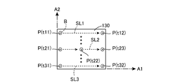
- FIG. 4 is a plan view showing an example of two-dimensional scanning on the light diffusing element 130 shown in FIG.
- the two-dimensional scanning method shown here is a method generally called raster scanning, and is used for scanning an electron beam in a CRT display. Specifically, first, at the scanning time t11, the scanning beam L120 is incident on the incident point P (t11) at the upper left corner, and the beam spot B is formed at this position.
- the example shown here is an example in the case where a light beam L110 having a circular cross section is emitted from the light source 110, and the position of the incident point P (t11) on the light diffusing element 130 is almost as shown by the broken line. A circular beam spot B is formed.
- the beam spot B moves from the left to the right along the scanning line SL1, and is incident at the scanning time t12.
- the position of the point P (t12) is reached.
- the beam spot B is returned to the position one line below the leftmost incident point P (t11), and after scanning from left to right again, the beam spot B is returned to the position one line below the left edge, ... and repeat the operation of ⁇ ⁇ .
- the beam spot B is returned from the incident point P (t32) at the lower right corner to the position of the incident point P (t11) at the upper left corner, and scanning for one frame is performed again (or incident).
- the scanning path for the previous one frame may be traced back from the point P (t32) to the incident point P (t11).
- the scanning line SL from the incident point P (t1) ⁇ P (t2) ⁇ P (t3) shown in FIG. 3 scans the incident point P (t21) ⁇ P (t22) ⁇ P (t23) shown in FIG. This corresponds to the line SL2.
- the vector scan is a scan in which the beam spot B is moved along an arbitrary vector defined on the light diffusing element 130. If the scanning member 120 is provided with a function of performing two-dimensional scanning, the beam spot B can be obtained by combining the scanning amount in the first diffusion axis A1 direction and the scanning amount in the second diffusion axis A2 direction. It is possible to move to an arbitrary position on the light diffusing element 130. That is, it is possible to perform scanning such that the beam spot B draws an arbitrary locus on the light diffusing element 130.
- the scanning control unit 150 shown as a block in FIG. 3 is actually configured by an electronic circuit or a computer, and the scanning member 150 draws a predetermined locus so that the incident point P of the scanning beam L120 on the light diffusing element 130 draws a predetermined locus. It serves to control 120 scans.
- the scanning control unit 150 causes the scanning beam L120 to be incident on the light diffusing element 130 so that the arbitrarily shaped pattern can be drawn. Scanning control for changing P two-dimensionally may be performed. Then, drawing can be performed by moving the drawing spot D on the illumination target surface S, and an illumination area LA having a predetermined shape can be formed.
- the light diffusing element 130 in the present invention is a component that receives the scanning beam L120 scanned by the scanning member 120, diffuses it, and emits the diffused light L130.
- the extent of spread of diffused light in the direction of the diffusion axis A1 (first diffusion angle ⁇ 1 in the case of the above-described embodiment) and the extent of spread of diffused light in the direction of the second diffusion axis A2 (implementation described above) In the case of the example, the anisotropic diffusion is performed so that the second diffusion angle ⁇ 2) is different.
- a diffractive optical element DOE: Diffractive Optical Element
- a holographic optical element HOE: Holographic Optical Element
- the light diffusing element 130 may be configured by a microlens array, a lenticular lens, a diffusing plate, or the like.
- a diffractive optical element having a function equivalent to that of the microlens array or lenticular lens may be used by incorporating the function of the microlens array or lenticular lens into the diffractive optical element.
- the light diffusing element 130 is configured by a diffractive optical element or a holographic optical element. These elements generate diffused light by the light diffraction phenomenon, and by adjusting the diffraction angle by devising the structure of the diffraction pattern to be recorded, it is possible to achieve the desired anisotropic diffusion characteristics. it can.
- the actual state of anisotropic diffusion caused by the light diffraction phenomenon will be described in more detail.
- FIG. 5 is a diagram showing a method of expressing the angular space distribution of the first-order diffracted light intensity emitted from one point P on the light diffusing element 130 using the displacement angles ⁇ V and ⁇ H. Note that although 0th-order diffracted light and second-order or higher-order diffracted light are also emitted from the light diffusing element 130, since the intensity of the first-order diffracted light is dominant in practice, only the first-order diffracted light is considered here. I will decide.
- the diffractive surface (light emitting surface) of the light diffusing element 130 is disposed on the XZ plane, and the incident light Lin is given at a predetermined incident angle, the position is at the coordinates (xp, yp, zp).
- FIG. 5 (a) is a projection view (projection view on the XY plane) of the XYZ three-dimensional orthogonal coordinate system from above, the right side of the figure is the Y-axis positive direction, and the lower side of the figure is the X-axis positive direction.
- the front direction perpendicular to the drawing sheet is the positive Z-axis direction.
- the light diffusing element 130 is arranged on the XZ plane of this coordinate system.
- the incident light Lin is given to the point P on the light diffusing element 130 from a predetermined direction
- the optical path (broken line) of the emitted light LoutL emitted from the point P as the first-order diffracted light.
- FIG. 5A shows how the first-order diffracted light Lout (broken line) emitted from the point P travels to an arbitrary point Q (xq, yq, zq) in the three-dimensional space.
- the first-order diffracted light Lout is emitted in a direction that forms a first direction displacement angle ⁇ H with respect to the normal Np (parallel to the Y axis) set at the point P.
- This first direction displacement angle ⁇ H corresponds to a displacement angle in the horizontal direction (direction along a horizontal plane parallel to the XY plane) with respect to the incident light Lin.
- the clockwise direction is the positive direction of the first direction displacement angle ⁇ H (the illustrated displacement angle ⁇ H takes a negative value).
- FIG. 5 (b) is a projected view (projected view on the YZ plane) of the XYZ three-dimensional orthogonal coordinate system from the side, with the right side of the figure on the Y axis positive direction and the upper side of the figure on the Z axis.
- the positive direction, the front direction perpendicular to the drawing sheet, is the X-axis positive direction.
- the light diffusing element 130 is disposed on the XZ plane of this coordinate system.
- the optical path (broken line) of the emitted light Lout that is emitted from the point P as the first-order diffracted light when the incident light Lin is given to the point P on the light diffusing element 130 from a predetermined direction.
- the first-order diffracted light Lout (broken line) emitted from the point P is directed to a point Q in the three-dimensional space (the same point as the point Q shown in FIG. 5 (a)).
- the first-order diffracted light Lout is emitted in a direction that forms a second direction displacement angle ⁇ V with respect to the normal line Np (parallel to the Y axis) set at the point P.
- This second direction displacement angle ⁇ V corresponds to the displacement angle in the vertical direction (direction parallel to the Z axis) with respect to the incident light Lin, and here, in the projection view shown in FIG. In the positive direction of the second direction displacement angle ⁇ V (the illustrated displacement angle ⁇ V takes a negative value).
- the traveling direction (diffraction direction) of one diffracted light LoutL emitted from an arbitrary point P of the light diffusing element 130 is two sets of first direction displacement angle ⁇ H and second direction displacement angle ⁇ V. It can be expressed by angle. That is, the directions of diffracted light from the point P (xp, yp, zp) to the point Q (xq, yq, zq) can be expressed by two sets of angles ( ⁇ H, ⁇ V).
- the direction of the first-order diffracted light emitted from a certain point P is the position coordinate of the distribution point R on the angular space distribution diagram expressed by the two-dimensional orthogonal coordinate system ⁇ H- ⁇ V as shown in FIG. Can be indicated by
- the distribution points R shown in FIG. 5C are points plotted at the coordinates indicated by the abscissa value ⁇ H (R) and the ordinate value ⁇ V (R) in this distribution diagram.
- b) The direction of the emitted light Lout shown in is shown.
- the projected image on the XZ plane is located at the lower left of the point P.
- the distribution point R shown in FIG. 5 (c) corresponds to the point Q shown in FIGS. 5 (a) ⁇ ⁇ ⁇ and (b), and is also located at the lower left of the point P.
- the example in which the incident light Lin is incident on one geometric point P on the light diffusing element 130 and the incident light Lin is changed in direction and emitted as one emitted light Lout is shown.
- the scanning beam L120 incident on the light diffusing element 130 forms a beam spot B having a certain area as shown in FIG.
- an optical phenomenon that occurs on the light diffusing element 130 at a certain scanning time point is that the region near the point P is irradiated with the beam spot B and diffused from the entire nearby region by the diffraction pattern formed in the nearby region.
- This is a phenomenon in which the light L130 spreads. Therefore, in practice, as shown in FIGS. 5A and 5B, one emission light Lout is not emitted from the point P, but is diffused from the vicinity of the point P with a certain spread width.
- the light L130 is emitted.
- the predetermined intensity value is determined for the intensity of the first-order diffracted light diffracted by the diffraction pattern near the point P.
- This is information indicating the angular space distribution, which is information indicating the diffraction characteristics of the diffraction pattern in the vicinity of the point P.
- an intensity value 100 is defined only at the position of the distribution point R ( ⁇ H (R), ⁇ V (R)) shown in FIG. 5 (c), and an intensity value 0 is defined for all other portions. As shown in FIGS.
- the light diffusing element 130 having the angular space distribution of the folding light intensity is obtained by converting only one emitted light Lin having an intensity value 100 to 1 with respect to the incident light Lin. This means an element having diffraction characteristics that is emitted as the next diffracted light.
- the angular space distribution of the first-order diffracted light intensity changes according to the incident angle of the incident light Lin.
- the incident angle is 0 °.
- the direction of the emitted light Lout is also changed, and the first direction displacement angle ⁇ H and the second direction angle are changed.
- the direction displacement angle ⁇ V also changes, and the angular space distribution shown in FIG. 5C changes. Therefore, the angular space distribution shown in FIG. 5 (c) represents the angular space distribution of the intensity of the first-order diffracted light obtained when the incident light Lin is irradiated near the point P at a specific incident angle.
- FIG. 6 is a diagram showing a state of the diffused light L130 emitted from the vicinity of the point P when the incident light Lin is given to the vicinity of the point P on the light diffusing element 130 arranged on the XZ plane.
- FIG. 6 (a) is a projection view (projection view on the XY plane) of the XYZ three-dimensional orthogonal coordinate system as viewed from above, as in FIG. 5 (a). The lower side of the figure is the positive direction of the X axis, and the front direction perpendicular to the drawing is the positive direction of the Z axis.
- FIG. 6 is a diagram showing a state of the diffused light L130 emitted from the vicinity of the point P when the incident light Lin is given to the vicinity of the point P on the light diffusing element 130 arranged on the XZ plane.
- FIG. 6 (a) is a projection view (projection view on the XY plane) of the XYZ three-dimensional orthogonal coordinate system as viewed from above,
- FIG. 6 (b) is a projected view (projected view on the YZ plane) of the XYZ three-dimensional orthogonal coordinate system viewed from the side, as in FIG. 5 (b), and the right side of the figure is the Y axis.
- the positive direction, the upper side in the figure is the Z-axis positive direction, and the front direction perpendicular to the drawing is the X-axis positive direction.
- the light diffusing element 130 is disposed on the XZ plane of this coordinate system.
- the area shown by hatching in the figure is the diffraction range of the diffused light L130.
- 6A and 6B for convenience, the state in which the diffused light L130 spreads from one point P is depicted, but in actuality, it is formed by the light beam irradiated as the incident light Lin.
- the diffused light L130 is emitted from the entire region near the point P corresponding to the beam spot B.
- Such diffraction characteristics can be shown as an angular space distribution of the first-order diffracted light intensity shown in the upper right frame of FIG.
- a rectangular diffracted light distribution region E (hatched portion) is shown.
- This diffracted light distribution region E has a specific range of the first direction displacement angle ⁇ H and the second direction displacement angle ⁇ V.
- the horizontal width corresponds to the first diffusion angle ⁇ 1
- the vertical width corresponds to the second diffusion angle ⁇ 2.
- the moving locus of the diffused light spot G shown in FIG. 10 corresponds to the moving locus of the beam spot B shown in FIG.
- the illustrated example is an example of performing raster scanning, and the diffused light spot G moves two-dimensionally along the scanning lines SL1,..., SL2,..., SL3,. .
- FIG. 10 is a diagram conceptually showing that the diffused light spot G moves in conjunction with the scanning of FIG. 4.
- the positions of the diffused light spots G (t11) to G (t32) are not necessarily accurate. Not something.
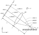
- the virtual projection plane M perpendicular to the optical axis of the illumination optical system 140 is defined at the front surface position of the illumination optical system 140, the light diffusing element 130 at each scanning time point.
- the diffused light beam L130 forms a rectangular diffused light spot G having a pair of long sides and a pair of short sides on the virtual projection plane M.
- a virtual projection plane M parallel to the XZ ′ plane is defined at the front surface position of the illumination optical system 140, the diffused light L130 emitted from each position of the light diffusing element 130 at each scanning time is On the virtual projection plane M, a rectangular diffused light spot G having a pair of long sides parallel to the X axis and a pair of short sides parallel to the Z ′ axis is formed.
- Each of the diffused light spots G (t11) to G (t32) shown in FIG. 10 is a rectangle having a pair of long sides parallel to the X axis and a pair of short sides parallel to the Z ′ axis. Yes.
- the optical path of the diffused light L130 (t21) is indicated by a solid line
- the optical path of the diffused light L130 (t31) emitted from the point P (t31) at the scanning time t31 is indicated by a one-dot chain line. Therefore, the illumination light L140 (t11) indicated by the broken line reaches the illumination target surface S at the scanning time t11, the illumination light L140 (t21) indicated by the solid line arrives at the scanning time t21, and the alternate long and short dash line at the scanning time t31. Illumination light L140 (t31) indicated by
- each optical path shown in FIG. 11 shows the central axis of the diffused light L130 and the illumination light L140, and actually the diffused light L130 and the illumination light L140 are lights having a predetermined width.
- the illumination optical system 140 is constituted by a collimator lens, and functions as a collimator that collimates the diffused light L130 from the light diffusing element 130. As shown in FIG. 10, the incident position of the diffused light L130 on the collimator lens 140 differs depending on each scanning time point t11 to t31.
- the cross section of the diffused light L130 is a rectangle having two long sides parallel to the X axis, the spread of the diffused light L130 in the X axis direction spreads in the Z ′ axis direction.
- the optical paths of the diffused light L130 (t21), the diffused light L130 (t22), and the diffused light L130 (t23) are drawn as optical paths having a spread.
- the illumination optical system 140 is configured by a collimator lens, the illumination light L140 (t21), the diffused light L140 (t22), and the diffused light L140 (t23) that have passed through the illumination optical system 140 are collimated.
- the illumination target surface S is reached.
- the drawing spot D formed on the illumination target surface S is also rectangular.
- the formation process of the illumination area LA in the example of the “tilted arrangement of the light diffusing elements” described in ⁇ 3.3 has been described above by taking the illuminating device 100 illustrated in FIG. 3 as an example, but described in ⁇ 3.2.
- the process of forming the illumination area LA in the “vertical arrangement of the light diffusing element” is substantially the same.
- the illumination optical system 140 has its optical axis parallel to the central axis of the diffused light L130 emitted from a predetermined point P on the emission surface of the light diffusing element 130 (for example, the center point of the emission surface). It is preferable to arrange in the direction. More preferably, the illumination optical system 140 may be arranged so that its optical axis coincides with the central axis of the diffused light L130 emitted from a predetermined point P on the emission surface of the light diffusing element 130.
- a virtual projection plane M orthogonal to the optical axis is defined at the front surface position of the illumination optical system 140, the diffused light L130 from the light diffusing element 130 is obtained at each scanning time point as in the example shown in FIG.
- a rectangular diffused light spot G having a pair of long sides parallel to the X axis and a short side composed of another pair of sides is formed on the virtual projection plane M. Therefore, a rectangular drawing spot D can be formed on the illumination target surface S.
- the incident position of the coherent light incident on the illumination optical system 140 changes according to the scanning of the scanning member 120.
- the traveling direction of the coherent light emitted from the collimating lens 140 also changes according to the incident position and the incident angle of the coherent light on the collimating lens 140.
- the position of the drawing spot D formed on the illumination target surface S also changes. Therefore, by controlling the scanning of the scanning member 120 by the scanning control unit 150, the drawing spot D can be moved on the illumination target surface S, and an illumination area LA composed of an arbitrarily shaped pattern can be formed.
- the illumination optical system 140 is not necessarily configured by a lens, and may be configured by using a curved mirror such as a concave mirror that performs an equivalent function. Even when a concave mirror is used as the illumination optical system 140, if the light diffusing element 130 is arranged at the focal position of the concave mirror, the coherent light reflected by the concave mirror travels in a substantially parallel direction, and the illumination target surface S Will be reached.
- the illumination device 100 shown in FIG. 3 can draw the illumination area LA having an arbitrary shape on the illumination target surface S by moving the drawing spot D.
- the inside of the arrow-shaped scanning area SA on the light diffusing element 130 (the hatched portion). Only the scanning in which the beam spot B is irradiated may be performed. As described above, such scanning can be performed by raster scanning or vector scanning.
- the movement of the drawing spot D on the illumination target surface S is linked to the movement of the beam spot B on the light diffusing element 130. Accordingly, data of a desired scanning pattern is prepared in the scanning control unit 150, scanning of the scanning member 120 is controlled according to this scanning pattern, and a desired figure is drawn by the beam spot B on the light diffusing element 130. If so, the desired figure can be drawn on the illumination target surface S by the drawing spot D.
- the first advantage of the present invention is that the drawing spot D formed by the diffused light L130 (diffused light obtained by an optical phenomenon) from the light diffusing element 130 is moved on the illumination target surface S to obtain a desired Since the illumination area LA having a shape is drawn, the illumination area LA having a high resolution can be obtained.
- the first advantage will be described in more detail with reference to a first comparative example using a phosphor.
- the lighting device 200 according to the first comparative example when used as a vehicle-mounted lighting device as shown in FIG. 2, the road surface in which the diameter of light emitted as fluorescence from the phosphor 230 becomes the illumination target surface S. Above, it is stretched in the Y-axis direction (depth direction as viewed from the driver), and the blur in the Y-axis direction cannot be overlooked.
- the phosphor 230 when the phosphor 230 is irradiated with coherent light having a minute spot diameter, there is a problem that the phosphor 230 burns or the edge of the phosphor 230 is deformed by heat, and is formed on the illumination target surface S.
- the pattern of the illumination area LA is not clear and blurring occurs.
- the illumination device 200 according to the first comparative example has a problem that the pattern of the illumination area LA formed on the illumination target surface S is blurred and the phosphor 230 is easily deteriorated.
- the illumination device 100 according to the present invention since the diffused light L130 is obtained by an optical phenomenon such as a diffraction phenomenon, the drawing spot D formed on the illumination target surface S is the first. Compared to the illumination device 200 according to the comparative example, the illumination area LA becomes much clearer and has a high resolution. Further, the problem of deterioration of the phosphor 230 does not occur.
- the second advantage of the present invention is that the light diffusing element 130 has a degree of spread of diffused light in the direction of the first diffusion axis A1 (first diffusion angle ⁇ 1 in the case of the above-described embodiment) and the second. Since the anisotropic diffusion is performed so that the degree of spread of the diffused light in the direction of the diffusion axis A2 (the second diffusion angle ⁇ 2 in the case of the above-described embodiment) is different, the safety against the coherent light is ensured. A clear illumination area LA in which blur is suppressed can be formed on the illumination target surface S.
- the second advantage will be described in more detail with reference to the second comparative example using the light diffusing element 135 that performs isotropic diffusion in the biaxial direction.
- FIG. 15 is a perspective view showing a basic configuration of an illumination device 100 ′ according to a second comparative example for the present invention.
- This illuminating device 100 ' has a light diffusing element 135 disposed in place of the light diffusing element 130 in the illuminating device 100 shown in FIG. 3, and this is the only difference between the two.
- the light diffusing element 130 shown in FIG. 3 has a degree of spread of diffused light in the direction of the first diffusion axis A1 and a degree of spread of diffused light in the direction of the second diffusion axis A2.
- the cross section of the diffused light L130 is a rectangle having two long sides parallel to the X axis.
- the diffused light spot G (t2) formed at the position of the illumination optical system 140 is also a rectangle having two sides parallel to the X axis as long sides.
- the drawing spot D (t2) formed on the illumination target surface S also has a rectangular shape corresponding to the diffused light spot G (t2).
- the drawing spot D (t2) in the Y-axis direction depends on the irradiation angle ⁇ shown in FIG. 2, the drawing spot D (t2) is not necessarily a rectangle having two sides parallel to the X axis as long sides. (Depending on the irradiation angle ⁇ , two sides parallel to the Y-axis may be long sides).
- the light diffusing element 135 shown in FIG. 15 has the same degree of spread of the diffused light in the direction of the first diffusion axis A1 and that of the diffused light in the direction of the second diffusion axis A2. Isotropic diffusion is performed. For this reason, the cross section of the illustrated diffused light L135 (t2) is square, and the diffused light spot J (t2) formed at the position of the illumination optical system 140 is also square. Accordingly, the drawing spot K (t2) formed on the illumination target surface S also has a rectangular shape corresponding to the diffused light spot J (t2).
- the diffused light spot G (t2) in the former becomes a diffused light spot J (t2) in the latter, and the drawing spot D (t2) in the former is different in the latter.
- the only point is the drawing spot K (t2).
- the important point between the two is that the diffused light spot G (t2) is a rectangle having two sides parallel to the X axis as long sides, whereas the diffused light spot J (t2) is square. This difference in the aspect ratio of the rectangle appears as a difference in the aspect ratio between the drawing spot D (t2) formed on the illumination target surface S and the drawing spot K (t2).
- the drawing spot D (t2) and the drawing spot K (t2) are obtained by projecting the diffused light spot G (t2) and the diffused light spot J (t2) from an oblique direction, and are collimated by the illumination optical system 140. Therefore, a rectangle is formed on the illumination target surface S. Then, the aspect ratio of the drawing spot D (t2) and the drawing spot K (t2) depends on the irradiation angle ⁇ shown in FIG. 2 (the smaller ⁇ is, the longer it is stretched in the Y-axis direction).
- the dimension of the drawing spot D (t2) in the Y-axis direction is smaller than the dimension of the drawing spot K (t2) in the Y-axis direction.
- reducing the size of the drawing spot in the Y-axis direction contributes to reducing the blur in the illumination area LA drawn by the movement of the drawing spot. The reason will be described below.
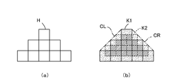
- a graphic pattern displayed on a display device is composed of an aggregate of pixels, and the resolution of the displayed graphic pattern greatly depends on the pixel size.
- FIG. 16A shows an example in which a graphic pattern composed of isosceles triangles is drawn by an assembly of pixels H indicated by solid squares.
- a low-resolution graphic that is considerably out of the original isosceles triangle is drawn.
- each drawing spot can be formed at an arbitrary position on the illumination target surface S by scanning with the scanning member 120. Therefore, for example, in FIG. 16B, the drawing spot K2 can be formed at a position indicated by a broken-line square.
- the drawing spot K2 is obtained by shifting the drawing spot K1 vertically and horizontally by half a pitch.
- FIG. 16B if a drawing spot K2 indicated by a broken-line square is further added to the drawing spot K1 indicated by a solid-line square, a graphic pattern consisting of an aggregate of the pixels H shown in FIG. On the other hand, a graphic pattern having double the resolution can be formed.
- the drawing spot K1 and the drawing spot K2 obtained by shifting the drawing spot by half a pitch are shown.
- the drawing spot can be continuously moved on the illumination target surface S. it can. Therefore, if appropriate two-dimensional scanning is performed by the scanning control unit 150, a graphic pattern having the left oblique contour line CL and the right oblique contour line CR as shown by the alternate long and short dash line in FIG. It is possible to obtain an isosceles triangle having a more accurate shape.
- a predetermined graphic pattern is drawn as an aggregate of pixels H
- a drawing spot K by illumination light is scanned to obtain a predetermined graphic pattern.
- the graphic pattern drawn by the drawing spot K has a potential problem that the outline portion is blurred.
- the reason for this can be easily understood by considering the luminance difference of each part when a graphic pattern is formed by a drawing spot K1 indicated by a solid line and a drawing spot K2 indicated by a broken line, as shown in FIG.
- the outline area hatched with dots is an area composed only of the drawing spot K1
- the inner area hatched with diagonal lines is the drawing spot K1 and the drawing spot K2. It becomes the area where both of them overlap.
- the hatched contour area is illuminated only when the illumination light is at the position of the drawing spot K1
- the hatched hatched inner area is illuminated with the drawing spot. Not only when it is at the position of K1, but also when the illumination light is at the position of the drawing spot K2.
- FIG. 17 is a diagram for explaining the reason why the outline of the graphic pattern is blurred when the graphic pattern is formed by the drawing spots.
- the horizontal axis is the Y axis
- the square-shaped drawing spot K is moved from left to right as indicated by white arrows along the Y axis. Shows the state.
- a drawing spot K1 indicated by a solid square indicates a drawing spot at the start point position
- a drawing spot K2 and K3 indicated by a broken line square indicates a drawing spot at a midway position
- a drawing spot K4 indicated by a solid line square A drawing spot at the end position is shown.
- FIG. 17B is a graph showing the cumulative irradiation time t of illumination light at each position on the Y axis when the drawing spot is moved from K1 to K4 as shown in FIG. 17A. .
- the cumulative irradiation time t of the illumination light rises gently at the left end and gently falls at the right end.
- the length of the ascending and descending sections matches the width W of the drawing spot K in the Y-axis direction. Since the cumulative irradiation time t of illumination light at a specific position on the Y-axis corresponds to the luminance value of illumination at the specific position, in the example shown in the figure, the luminance value changes gently in the vicinity of the left end and the vicinity of the right end.
- the outline is blurred.
- FIG. 17C shows a state in which the drawing spot D is moved from the left to the right along the Y axis as indicated by the white arrow on the illumination target surface S, as in FIG. Is shown.
- the drawing spot K shown in FIG. 17A is a square-shaped drawing spot having a width W in the Y-axis direction
- the drawing spot D shown in FIG. 17C has a width ⁇ in the Y-axis direction.
- the drawing spot D1 indicated by the solid rectangle indicates the drawing spot at the starting point position
- the drawing spots D2 and D3 indicated by the broken rectangle indicate the drawing spots at the midpoint
- the drawing spot indicated by the solid line rectangle D4 indicates a drawing spot at the end point position.
- FIG. 17 (d) ⁇ ⁇ ⁇ is a graph showing the cumulative irradiation time t of illumination light at each position on the Y axis when the drawing spot is moved from D1 to D4 as shown in FIG. 17 (c). .
- the accumulated irradiation time t of the illumination light rises at the left end and falls at the right end, and the length of this rise and fall interval coincides with the width ⁇ of the drawing spot D in the Y-axis direction.
- the luminance value changes near the left end and near the right end, resulting in blurring of the outline.
- the region where the outline blur occurs is an interval of the width W reaching the coordinate values y1 to y3.
- the drawing spot D having the width ⁇ in the Y-axis direction is used as shown in FIG.
- the resulting region is a section of width ⁇ reaching the coordinate values y1 to y2 and a section of width ⁇ reaching the coordinate values y6 to y7.
- the width of the drawing spot in the Y-axis direction is an important parameter that affects the amount of blurring that occurs in the vicinity of the contour line.
- the center position of K4 and the center position of D4 substantially coincide.
- the actual position of the drawing spot K1 is slightly leftward from the illustrated position
- the position of the drawing spot K4 is slightly rightward from the illustrated position. Therefore, when the beam scanning mode by the scanning member 120 is the same, the illumination area LA (arrow figure) shown in FIG. 15 is more end in the Y-axis direction than the illumination area LA (arrow figure) shown in FIG.
- the edge of the portion is slightly stretched in the Y-axis direction, and blurring based on the above-described cause occurs in this portion.
- the drawing spot D instead of the drawing spot K, the drawing spot D having a small width in the Y-axis direction is used. The effect of reducing the amount is obtained.
- the lighting device 100 and the lighting device 100 ′ are used for the amount of blurring that occurs near the contour formed at the end in the X-axis direction. There is no change. However, when used as an in-vehicle lighting device as shown in FIG. 2, the contour line formed at the end in the Y-axis direction is more blurred than the contour line formed at the end in the X-axis direction. Countermeasures are much more important. In the case of an in-vehicle lighting device, as shown in FIG. 2, an illumination area 20 is formed on the road surface 10 that is considerably forward. Therefore, the graphic pattern constituting the illumination area 20 is stretched in the Y-axis direction. This is because it is presented.
- the driver's eyes will see an illumination area 20 consisting of a graphic pattern of an arrow ahead, but the actual illumination area 20 formed on the road surface 10 is
- the horizontal width width in the X-axis direction
- the vertical width width in the Y-axis direction
- the graphic pattern projected on the road surface 10 is stretched in the Y-axis direction
- blurring in the vicinity of the outline of the end portion (the tip portion and the root portion of the arrow) in the Y-axis direction is emphasized.
- the blurring of the contour line generated at the end in the Y-axis direction becomes very remarkable.
- a contour line formed at the end in the Y-axis direction Anti-blurring is very important.
- the diffused light L130 having a rectangular cross section having two sides parallel to the X axis as long sides and the other two sides as short sides is generated. Since the drawing spot D is formed on the illumination target surface S by the light L130, the outline blur formed at the end in the Y-axis direction is more effective than the illumination device 100 ′ shown in FIG. Can be suppressed.
- the diffused light L130 used in the illumination device 100 shown in FIG. 3 has a cross section of a rectangular shape having two sides parallel to the X axis as long sides, and therefore relates to the X axis direction (the direction of the first diffusion axis A1).
- the degree of spread of the diffused light can be made sufficiently large.
- the second diffusion angle ⁇ 2 indicating the extent of the diffused light with respect to the Z-axis direction (the direction of the second diffusion axis A2) is kept small (FIG. 6 (b)).
- the first diffusion angle ⁇ 1 indicating the degree of spread of the diffused light in the X-axis direction is set to be sufficiently large (see FIG. 6A). This is important in ensuring safety against coherent light.
- the first diffusion angle ⁇ 1 is suppressed to be small as well as the second diffusion angle ⁇ 2
- the extent of diffused light in the X-axis direction can be reduced, and the end of the illumination area LA in the X-axis direction can be reduced.
- the merit that the formed outline can be sufficiently prevented is obtained, coherent light having a high energy density is directly irradiated onto the illumination target surface S, and safety is impaired. Serious problems will arise.
- the road surface 10 when illuminating the road surface 10 using an in-vehicle lighting device, when the pedestrian 30 turns his / her line of sight toward the lighting device 100 incorporated in the vehicle 40, the road surface 10 is headed.
- coherent light is directly incident on the eyes of the pedestrian 30.
- the energy density of the coherent light emitted as illumination light from the lighting device 100 is high, the eyes of the pedestrian 30 may be damaged.
- the first diffusion angle ⁇ 1 can be set sufficiently large while keeping the second diffusion angle ⁇ 2 small. For this reason, the energy density of the light beam emitted from the light source 110 is dispersed in the X-axis direction according to the first diffusion angle ⁇ 1, and sufficient safety can be ensured.
- the coherent light beam L110 from the light source 110 is scanned by the scanning member 120 and is incident on the light receiving surface of the light diffusing element 130.
- the incident scanning beam L120 is emitted as diffused light L130, and forms a drawing spot D on the illumination target surface S via the illumination optical system 140.
- the scanning control unit 150 controls the scanning of the light beam according to the arrow-shaped graphic pattern, the illumination area LA having the arrow shape is formed on the illumination target surface S by the moving drawing spot D. It is formed.
- the light diffusing element 130 performs anisotropic diffusion that spreads the incident light beam mainly in the X-axis direction, the spread of the diffused light L130 is biased in one direction.
- the basic feature of the present invention that “the light diffusing element 130 performs anisotropic diffusion” is a clear illumination region in which blurring is suppressed on the illumination target surface S while ensuring safety against coherent light.
- This is a very important feature in obtaining the effect of forming the film. That is, by performing illumination using the diffused light L130 sufficiently expanded in the direction of the first diffusion axis A1, the energy density of the coherent light irradiated as the illumination light is reduced, and practically sufficient safety is achieved. It becomes possible to secure.
- the drawing spot D by using the diffused light L130 in which the spread in the direction of the second diffusion axis A2 is limited, the outline of the illumination area LA drawn by the drawing spot D is blurred. And a clear illumination region can be formed.
- the blur suppression effect based on the above configuration is effective for the contour line formed at the end portion in the Y-axis direction, but is not effective for the contour line formed at the end portion in the X-axis direction.
- the contour line formed at the end in the Y-axis direction Since the anti-blurring measure is very important as compared with the anti-blurring measure of the contour line formed at the end in the X-axis direction, the blur suppression effect according to the present invention is a very practical effect.
- the first diffusion axis is used.
- Ratio of spread of diffused light in the direction of A1 to spread of diffused light in the direction of the second diffusion axis A2 (value of ⁇ 1 / ⁇ 2 where ⁇ 1 is the first diffusion angle and ⁇ 2 is the second diffusion angle)
- the value of the width / length of the rectangle constituting the cross section of the diffused light L130 shown in FIG. 8 is obtained by some experiments. If the ratio is set to 2 or more, the coherent light can be obtained.
- the ratio is 2 or more, preferably 5 or more, more preferably 10 It is good to set it above.
- the illumination device 100 in order to form the illumination area LA having an arrow shape as shown in FIG. 3, as shown in FIG. It is necessary to perform scanning so that the beam spot B moves only within the scanning area SA of the arrow graphic.
- the scanning of the beam spot B on the light diffusing element 130 is always performed by raster scanning on the entire surface as shown in FIG.
- the lighting control of the light lighting control unit 160 can be arbitrarily performed.
- a shaped illumination area LA can be formed.
- FIG. 19 is a perspective view (partially a block diagram) showing a basic configuration of a color illumination device 400 according to a modification of the present invention.
- this color illumination device 400 three sets of illumination devices 100 shown in FIG. 3 are prepared so that an illumination area LA having an arbitrary color can be formed on the illumination target surface S.
- these three sets of lighting devices are referred to as a first lighting device, a second lighting device, and a third lighting device.
- the scanning control unit 150R of the first lighting device, the scanning control unit 150G of the second lighting device, and the scanning control unit 150B of the third lighting device may be provided separately, but in FIG. In the illustrated embodiment, an integrated scanning control unit 155 that integrates these is provided.
- the integrated scanning control unit 155 has a function of performing scanning control of the scanning members 120R, 120G, and 120B for each color.
- the illumination device 400 shown in FIG. 19 is additionally provided with a red light source lens 115R, a green light source lens 115G, and a blue light source lens 115B. ing. These light source lenses serve to increase the parallelism of the light beams emitted from the respective light sources.
- the light diffusing element 130R of the first illuminating device forms a red illumination area by the red diffused light via the red illumination optical system 140R.
- the light diffusing element 130G of the second illuminating device forms a green illumination region by the green diffused light via the green illumination optical system 140G
- the light diffusing element 130B of the third illuminating device is A blue illumination area is formed by the blue diffused light via the blue illumination optical system 140R. Therefore, a red illumination area, a green illumination area, and a blue illumination area are formed on the illumination target surface S, and a color illumination area of a predetermined color is formed in an overlapping portion of the illumination areas of these colors.
- the point that the light diffusing elements 130R, 130G, and 130B for each color perform anisotropic diffusion is the same as in the basic embodiment described so far. It has also been described so far that the illumination optical systems 140R, 140G, and 140B for the respective colors are configured by collimating lenses, and the light diffusion elements 130R, 130G, and 130B for the respective colors are disposed at the front focal positions thereof. This is the same as the basic embodiment. Accordingly, the illumination optical systems 140R, 140G, and 140B for each color collimate the incident diffused light and emit it toward the illumination target surface S.
- the color of the color illumination area can be changed to any color by adjusting the output of the three sets of light sources 110R, 110G, and 110B.
- FIG. 19 an example has been described in which light sources that generate light beams of three colors of red, green, and blue are used as the three sets of light sources 110R, 110G, and 110B.
- the light source that generates coherent light of a color other than red, green, and blue may be used, or four or more sets of illumination devices may be used to combine four or more colors to form a color illumination area. You may make it form.
- a plurality of sets of light sources having the same wavelength region may be provided to improve the illumination intensity in the color illumination region.
- each component shown in FIG. 19 shows an example, and various other arrangements can be used.
- FIG. 20 is a perspective view showing an illumination device using a reflective scanning member according to a modification of the present invention.
- the scanning member 120 of the illumination device 100 shown in FIG. 3 is replaced with a scanning member 125, and the arrangement of the light sources 110 is slightly changed. Therefore, the light source 110, the light diffusing element 130, the illumination optical system 140, and the scanning control unit 150 illustrated in FIG. 20 are substantially the same components as the components having the same reference numerals used in the illumination device 100 illustrated in FIG. is there.
- the scanning member 120 shown in FIG. 3 is a transmissive scanning member, and performs scanning by rotating a transmissive scanning body that emits light incident on the first surface from the second surface. Therefore, the light beam L110 passes through the transmission type scanning body and enters the light diffusing element 130.
- the scanning member 125 shown in FIG. 20 is a reflection-type scanning member, and has a reflection surface that reflects and emits an incident light beam L110 (indicated by reference numeral 125 in the figure). And a scanning mechanism (elements composed of motors, gears, and the like: not shown) that rotate and scan the reflective scanning body.
- the reflective scanning body for example, a reflective mirror such as a MEMS (Micro Electro Mechanical Systems) mirror can be used.
- the traveling direction of the reflected light beam can be changed by rotating the reflection mirror around a predetermined rotation axis by the scanning mechanism.
- the reflection type scanning body may be rotated around the rotation axis by the scanning mechanism with the axis parallel to the Z ′ axis as the rotation axis.
- the light beam L110 from the light source 110 reflects the reflective scanning body, and the reflected scanning beam L125 travels to the light diffusing element 130.
- a scanning mechanism that scans by rotating the reflective scanning body about two axes is prepared, and the scanning control unit 150 determines the incident point of the scanning beam L125 on the light diffusing element 130 in two dimensions. It is sufficient to perform scanning control that is changed as desired. For example, if a scanning mechanism capable of rotating around a first rotation axis parallel to the Z ′ axis and rotating around a second rotation axis parallel to the X axis is used, the reflected light The beam spot B formed on the light diffusing element 130 by the beam can be moved by two-dimensional scanning as shown in FIG.
- FIG. 21 is a perspective view showing the function of the light diffusing element 170 having the element diffractive optical region used in the modification of the present invention.
- the light diffusing element 130 in the illumination device 100 shown in FIG. 3 can be configured by a holographic optical element in which a predetermined diffraction pattern is recorded.
- the light diffusing element 170 shown in FIG. 21 is also an example of a light diffusing element configured by a holographic optical element, but this light diffusing element 170 is divided into a plurality of regions as shown in FIG. Each function as an independent hologram.
- the light diffusing element 170 shown in FIG. 21 may be used instead of the light diffusing element 130 in the illumination device 100 shown in FIG.
- individual regions constituting the light diffusing element 170 are referred to as element diffractive optical regions.
- the diffused light emitted from the individual element diffractive optical regions is separated into different drawing spots D at different positions on the illumination target surface S via the illumination optical system 140 (not shown in FIG. 21).
- the diffused light from the element diffractive optical region 171 shown hatched in the figure passes through the illumination optical system 140 (not shown) and forms a drawing spot D1 on the illumination target surface S.
- the diffused light from the element diffractive optical region 172 forms a drawing spot D2 on the illumination target surface S
- the diffused light from the element diffractive optical region 173 forms a drawing spot D3 on the illumination target surface S.
- the other element diffractive optical regions since the collimation is performed by the illumination optical system 140 (not shown), the illumination light incident on the illumination target surface S becomes parallel light.
- independent individual holograms are recorded in the individual element diffractive optical areas, and these individual holograms are not shown when the scanning beam L120 from the scanning member 120 is received. It has a function of emitting diffused light that forms separate drawing spots D at individual positions on the illumination target surface S through the system 140.
- the individual hologram recorded in the element diffractive optical area 171 forms a drawing spot D1 on the illumination target surface S through the illumination optical system 140 (not shown) when the scanning beam L120 is incident from a predetermined direction. It has a function of emitting a diffused light.
- the scanning beam L120 from the scanning member 120 is irradiated on the back surface of the light diffusing element 170 shown in FIG.
- the beam spot B moves two-dimensionally on the light diffusing element 170, and predetermined diffused light is emitted from the element diffractive optical region at the moving location.
- the drawing spot D1 shown in the figure on the illumination target surface S is formed.
- the beam spot B When the diameter of the beam spot B is larger than the dimension of each element diffractive optical region, the beam spot B covers a plurality of adjacent element diffractive optical regions at a certain scanning time.
- the drawing spots D are formed at different positions by the diffused light from the individual element diffractive optical regions, and a plurality of drawing spots D appear on the illumination target surface S. Since an illumination area LA having a predetermined shape is formed as an aggregate of spots D, no trouble occurs.
- the same drawing is performed on the illumination target surface S as long as the beam spot B remains in the same element diffractive optical region. A spot will appear. However, if the beam spot B moves into the adjacent element diffractive optical region, a drawing spot appears at a different position, so that no problem is caused.
- the drawing spot appears at the same position as long as the beam spot B stays in the same element diffractive optical region. Instead, it becomes discrete.
- the scanning speed by the scanning control unit 150 is set to be somewhat high, the illumination area LA formed on the illumination target surface S is a single area for the human eye even if the drawing spot moves discretely. There is no change in the point that is visually recognized, and no particular problem occurs.
- the illumination region LA is formed by superimposing the coherent light from each element diffractive optical region, so that the safety of the coherent light is further improved. At the same time, there is an advantage that speckles are difficult to see.
- each element diffractive optical region is diffused in the direction of the first diffusion axis and diffused in the direction of the second diffusion axis, as in the embodiments described above. It is obtained by anisotropic diffusion with a different degree of light spread, and its cross section has a rectangular shape as shown in FIG. Therefore, even when the light diffusing element 170 is used, the function and effect unique to the present invention described in section 5 can be obtained.
- the individual hologram recorded in each element diffractive optical area includes, for example, a hologram having a function of forming a reproduction image of a rectangular surface (a rectangular surface having a certain aspect ratio) at an arbitrary position in a three-dimensional space.
- a hologram having a function of forming a reproduction image of a rectangular surface (a rectangular surface having a certain aspect ratio) at an arbitrary position in a three-dimensional space.
- Such an individual hologram is an optical process (for example, a diffusion plate having a rectangular surface is arranged at a predetermined position in a three-dimensional space, and object light and predetermined reference light from the rectangular surface of the diffusion plate are arranged.
- the process of recording interference fringes on a photosensitive medium is also possible. However, in practice, the interference fringes determined by computer calculations are recorded on a physical structure using the CGH method. It is preferable to create it.
- FIG. 21 also shows an example in which the drawing spot D is set to move according to the scanning direction for the convenience of explanation in the modification using the element diffractive optical region shown in FIG.
- the position of the hologram reproduction image can be arbitrarily set.
- the drawing spot D2 is set to be formed by the diffracted light from the element diffractive optical region 171
- the drawing spot D3 is set to be formed by the diffracted light from the element diffractive optical region 172. You can also.
- at which position the drawing spot D is formed by the diffracted light from which element diffractive optical region can be arbitrarily determined at the time of design.
- the scanning direction of the incident light with respect to the light diffusing element 170 and the moving direction of the drawing spot D on the illumination target surface S can be set completely independently.
- the drawing spot D is moved in the Y-axis direction while the light beam is scanned in the X-axis direction, the drawing spot D is moved zigzag, or the drawing spot D is moved to a completely random position. it can.
- This feature can greatly contribute to achieving the object of the present invention to ensure safety against coherent light.
- the movement path of the drawing spot D on the illumination target surface S is along a predetermined trajectory corresponding to the scanning path of the light beam, the human eye with the line of sight in the direction of the light source is exposed from the light source. Light will enter continuously.
- the illumination direction can be dispersed, so that the light source entering the human eye It becomes possible to disperse the light from and improve safety.
- each element diffractive optical region has a predetermined value so that the scanning path of the light beam by the scanning member 120 and the movement path of the drawing spot D on the illumination target surface S are different. It is possible to record a diffraction pattern having the above diffraction characteristics, and by doing so, it is possible to disperse light from a light source entering the human eye and improve safety.
- the use of the illumination device according to the present invention is not necessarily limited to the vehicle-mounted illumination device, and can be used for, for example, an application in which an illumination area having a predetermined shape is formed on a wall surface of a building. . Therefore, depending on the use environment, there may be a case where the countermeasure against the blurring of the contour line formed at the end portion in the X-axis direction is more important than the countermeasure against the blurring of the contour line formed at the end portion in the Y-axis direction. Further, even when used in an in-vehicle illumination device as shown in FIG.
- a light diffusing element that emits diffused light having a cross-sectional shape obtained by rotating the figure shown in FIG. 8 by 90 ° may be used. That is, in the embodiments so far, as shown in the upper right frame of FIG. 7, the light diffusing element that can obtain the first-order diffracted light having the angular space distribution indicated by the horizontally long rectangle is used.
- a light diffusing element capable of obtaining first-order diffracted light having an angular space distribution represented by a vertically long rectangle may be used. If it does so, instead of the blurring countermeasure of the outline formed in the edge part regarding a Y-axis direction, the illumination which gave the blurring countermeasure of the contour line formed in the edge part regarding an X-axis direction can be performed.
- the main point of the present invention is that when the first diffusion axis and the second diffusion axis are defined on the light emission surface of the light diffusing element 130, the light diffusing element 130 transmits diffused light in the first diffusion axis direction.
- the anisotropic diffusion is performed such that the extent of spreading differs from the extent of spreading of diffused light in the second diffusion axis direction.
- the first diffusion axis is set in the direction parallel to the X axis
- the second diffusion axis is set in the direction parallel to the Z axis or the Z ′ axis
- diffusion in the first diffusion axis direction is performed.
- the degree of spread of light is set to be larger than the degree of spread of diffused light in the second diffusion axis direction.
- the illumination device 600 shown in FIG. 22 is a modified example using the reflective scanning member 125 as in the illumination device 500 shown in FIG. 20, but is an example in which the device is configured using a larger number of lenses. That is, in the illumination device 600, the collimating lens 180 is disposed between the light source 111 and the reflective scanning member 125, and the condensing lens 190 is disposed between the reflective scanning member 125 and the light diffusing element 130. Has been. Moreover, the illumination optical system 140 is comprised by the lens group which consists of a some lens as illustration.
- the light source 111 used in this modification is of a type that diverges laser light from a point light source, and the coherent light from the light source 111 is not a thin light beam, but is a divergence that spreads conically from the position of the point light source. Emitted as light.
- the collimating lens 180 serves to collimate the coherent light from the point light source. Therefore, parallel light having a width (having a circular cross section) is incident on the reflective scanning member 125 as shown in the figure.
- the reflection-type scanning member 125 is configured by a movable mirror that rotates as indicated by an arrow in the drawing under the control of the scanning control unit 150, and the parallel light reflected by the movable mirror passes through the condenser lens 190. The light is incident on the incident surface of the light diffusing element 130.
- the coherent light collected by the condensing lens 190 is minute on the incident surface of the light diffusing element 130.
- a beam spot B is formed.
- the point that the beam spot B is scanned on the light diffusing element 130 by the scanning member 125 is the same as in the basic embodiment described so far.
- the point that the coherent light irradiated to the light diffusing element 130 as the beam spot B is anisotropically diffused and goes to the illumination optical system 140 is the same as in the basic embodiment described so far.
- the illumination optical system 140 is configured by a plurality of lenses, but the point that the illumination optical system 140 plays the role of a collimating lens is the same as in the basic embodiment described so far.
- the illumination light emitted from the illumination optical system 140 goes to the illumination target surface S as parallel light.
- the present invention provides an illuminating device capable of forming a clear illumination area with reduced blur on an illumination target surface while ensuring safety against coherent light, and has the following various aspects. .
- a basic aspect of the present invention includes a light source that emits coherent light, a light diffusing element that anisotropically diffuses incident coherent light, and scans the coherent light emitted from the light source on the light diffusing element.
- the present invention relates to an illumination device including a scanning member and an illumination optical system that guides the anisotropically diffused coherent light to an illuminated area.
- One embodiment of the present invention is such that, in the illumination device, the light diffusing element is disposed at a front focal position of the illumination optical system.
- One embodiment of the present invention is such that, in the illumination device, the light diffusing element diffuses coherent light scanned by the scanning member in a uniaxial direction.
- One aspect of the present invention is the illumination apparatus, wherein the light diffusing element transmits coherent light scanned by the scanning member between a normal direction of the illuminated region and an optical axis center direction of the illumination optical system. It is intended to diffuse in the normal direction of the passing surface.
- One embodiment of the present invention is the illumination device, wherein the light diffusing element diffuses coherent light in a predetermined direction with a size larger than a beam spot size of the coherent light incident from the scanning member incident on the light diffusing element. In the direction crossing the predetermined direction, coherent light is diffused with the size of the beam spot.
- One aspect of the present invention is the illumination device, wherein the illumination optical system has an illumination position in the illuminated area according to an incident position of the coherent light diffused by the light diffusing element to the illumination optical system.
- the illumination range in which at least one of the illumination shape and the illumination size is different is illuminated.
- the illumination optical system is a lens, a concave mirror, or a curved mirror in the illumination device.
- One embodiment of the present invention is such that, in the illumination device, the light diffusing element is a diffractive optical element or a holographic optical element.
- the illumination target surface S is illuminated by collimating the coherent light from the light diffusing element 130 that performs anisotropic diffusion with the optical illumination system 140 such as a lens.
- Illumination blur in the illumination area LA formed on the illumination target surface S can be suppressed, and an illumination pattern of an arbitrary shape can be clearly displayed. For this reason, even when an observer near the illumination area LA observes the illumination pattern, this can be correctly recognized.
- the light diffusing element 130 greatly diffuses the coherent light from the scanning member 120 in a predetermined direction, even if an observer turns his eyes from the illumination area LA side to the light source 110 side, the light diffusing element 130 has a light intensity that hurts the eyes. It is possible to design so that the coherent light does not enter the eyes of the observer, and the safety of the coherent light can be improved.
- the illuminating device according to the present invention can be widely used for the purpose of performing illumination by forming an illumination area having an arbitrary shape on a predetermined illumination target surface.
- it is optimal for use in an illumination environment in which the angle formed by the optical axis of illumination light and the surface to be illuminated is small, such as for lighting a road surface of a road.
Abstract
Priority Applications (4)
| Application Number | Priority Date | Filing Date | Title |
|---|---|---|---|
| CN201880033300.6A CN110678789B (zh) | 2017-05-22 | 2018-05-18 | 照明装置 |
| EP18806189.9A EP3633266A4 (fr) | 2017-05-22 | 2018-05-18 | Dispositif d'éclairage |
| JP2019520212A JP7092123B2 (ja) | 2017-05-22 | 2018-05-18 | 照明装置 |
| US16/609,556 US11092305B2 (en) | 2017-05-22 | 2018-05-18 | Illumination device |
Applications Claiming Priority (2)
| Application Number | Priority Date | Filing Date | Title |
|---|---|---|---|
| JP2017101101 | 2017-05-22 | ||
| JP2017-101101 | 2017-05-22 |
Publications (1)
| Publication Number | Publication Date |
|---|---|
| WO2018216609A1 true WO2018216609A1 (fr) | 2018-11-29 |
Family
ID=64395604
Family Applications (1)
| Application Number | Title | Priority Date | Filing Date |
|---|---|---|---|
| PCT/JP2018/019262 WO2018216609A1 (fr) | 2017-05-22 | 2018-05-18 | Dispositif d'éclairage |
Country Status (5)
| Country | Link |
|---|---|
| US (1) | US11092305B2 (fr) |
| EP (1) | EP3633266A4 (fr) |
| JP (1) | JP7092123B2 (fr) |
| CN (1) | CN110678789B (fr) |
| WO (1) | WO2018216609A1 (fr) |
Cited By (1)
| Publication number | Priority date | Publication date | Assignee | Title |
|---|---|---|---|---|
| JP7400403B2 (ja) | 2019-11-28 | 2023-12-19 | 大日本印刷株式会社 | 照明装置、光学部材、照明システム及び照明方法 |
Families Citing this family (4)
| Publication number | Priority date | Publication date | Assignee | Title |
|---|---|---|---|---|
| JP2021068629A (ja) * | 2019-10-25 | 2021-04-30 | 市光工業株式会社 | 車両用灯具 |
| CN112304959B (zh) * | 2020-12-28 | 2021-03-30 | 维嘉数控科技(苏州)有限公司 | 用于检测设备的光源控制装置、方法及检测设备 |
| CN114035319B (zh) * | 2021-11-24 | 2023-05-26 | 重庆紫光华山智安科技有限公司 | 透镜设计方法及相关装置 |
| FR3133036B1 (fr) * | 2022-02-28 | 2024-02-02 | Valeo Vision | Système de projection compact de motifs en champ proche |
Citations (4)
| Publication number | Priority date | Publication date | Assignee | Title |
|---|---|---|---|---|
| JP2012146621A (ja) | 2010-12-20 | 2012-08-02 | Stanley Electric Co Ltd | 車両用灯具 |
| JP2015132707A (ja) | 2014-01-14 | 2015-07-23 | 大日本印刷株式会社 | 表示装置及び表示装置が搭載された車両 |
| JP2015212824A (ja) * | 2010-09-08 | 2015-11-26 | 大日本印刷株式会社 | 照明装置 |
| JP2016029488A (ja) * | 2015-09-25 | 2016-03-03 | 大日本印刷株式会社 | 照明装置および光偏向装置 |
Family Cites Families (13)
| Publication number | Priority date | Publication date | Assignee | Title |
|---|---|---|---|---|
| JPS5596475A (en) * | 1979-01-19 | 1980-07-22 | Nissan Motor Co Ltd | Obstacle detector for vehicle |
| DE4215584C2 (de) | 1992-05-12 | 2002-06-20 | Bosch Gmbh Robert | Beleuchtungseinrichtung mit einem Reflektor und mit optisch wirksamen Elementen |
| IT1261132B (it) * | 1993-12-23 | 1996-05-09 | Carello Spa | Reticolo di diffrazione atto a generare un flusso di radiazione luminosa con distribuzione di intensita' prefissata in un'area sottendente il flusso stesso. |
| JP5282368B2 (ja) * | 2007-01-31 | 2013-09-04 | 株式会社リコー | 画像読取装置、および画像形成装置 |
| JP5698065B2 (ja) * | 2011-04-22 | 2015-04-08 | 株式会社小糸製作所 | 障害物検出装置 |
| JP2013125693A (ja) * | 2011-12-15 | 2013-06-24 | Koito Mfg Co Ltd | 車両用灯具 |
| JP6323743B2 (ja) * | 2013-12-13 | 2018-05-16 | 大日本印刷株式会社 | 光走査装置、照明装置、投射装置および光学素子 |
| JP6411771B2 (ja) * | 2014-04-16 | 2018-10-24 | 株式会社小糸製作所 | 車両用灯具 |
| AT516113B1 (de) * | 2014-08-12 | 2017-12-15 | Zkw Group Gmbh | Scheinwerfer für Kraftfahrzeuge mit Lasereinheit |
| EP3216650A4 (fr) | 2014-11-07 | 2018-06-13 | Dai Nippon Printing Co., Ltd. | Dispositif d'éclairage |
| JP6653521B2 (ja) | 2015-01-23 | 2020-02-26 | 株式会社小糸製作所 | 路面描画用灯具ユニット |
| EP3507640A1 (fr) * | 2016-08-31 | 2019-07-10 | Lumileds Holding B.V. | Source de lumière à base de laser avec motif d'éclairage personnalisé |
| EP3564073B1 (fr) * | 2016-12-28 | 2023-07-05 | Dai Nippon Printing Co., Ltd. | Appareil d'éclairage |
-
2018
- 2018-05-18 US US16/609,556 patent/US11092305B2/en active Active
- 2018-05-18 JP JP2019520212A patent/JP7092123B2/ja active Active
- 2018-05-18 EP EP18806189.9A patent/EP3633266A4/fr active Pending
- 2018-05-18 CN CN201880033300.6A patent/CN110678789B/zh active Active
- 2018-05-18 WO PCT/JP2018/019262 patent/WO2018216609A1/fr active Application Filing
Patent Citations (4)
| Publication number | Priority date | Publication date | Assignee | Title |
|---|---|---|---|---|
| JP2015212824A (ja) * | 2010-09-08 | 2015-11-26 | 大日本印刷株式会社 | 照明装置 |
| JP2012146621A (ja) | 2010-12-20 | 2012-08-02 | Stanley Electric Co Ltd | 車両用灯具 |
| JP2015132707A (ja) | 2014-01-14 | 2015-07-23 | 大日本印刷株式会社 | 表示装置及び表示装置が搭載された車両 |
| JP2016029488A (ja) * | 2015-09-25 | 2016-03-03 | 大日本印刷株式会社 | 照明装置および光偏向装置 |
Non-Patent Citations (1)
| Title |
|---|
| See also references of EP3633266A4 |
Cited By (1)
| Publication number | Priority date | Publication date | Assignee | Title |
|---|---|---|---|---|
| JP7400403B2 (ja) | 2019-11-28 | 2023-12-19 | 大日本印刷株式会社 | 照明装置、光学部材、照明システム及び照明方法 |
Also Published As
| Publication number | Publication date |
|---|---|
| JP7092123B2 (ja) | 2022-06-28 |
| CN110678789A (zh) | 2020-01-10 |
| EP3633266A4 (fr) | 2021-02-17 |
| US20200063933A1 (en) | 2020-02-27 |
| EP3633266A1 (fr) | 2020-04-08 |
| CN110678789B (zh) | 2021-12-24 |
| US11092305B2 (en) | 2021-08-17 |
| JPWO2018216609A1 (ja) | 2020-03-26 |
Similar Documents
| Publication | Publication Date | Title |
|---|---|---|
| US11530792B2 (en) | Illumination device and method of manufacturing the same | |
| WO2018216609A1 (fr) | Dispositif d'éclairage | |
| JP7022394B2 (ja) | 照明装置 | |
| US10837617B2 (en) | Illumination device | |
| JP6713869B2 (ja) | 車両用灯具 | |
| US11131964B2 (en) | Illumination device | |
| JP6803009B2 (ja) | 照明装置 | |
| WO2018128162A1 (fr) | Dispositif d'éclairage | |
| JP6939315B2 (ja) | 照明装置 | |
| JP2019021471A (ja) | 照明装置 | |
| JP2022130103A (ja) | 照明システム、照明システムの設計方法 | |
| US10462435B2 (en) | Image display device and screen for car windshield and manufacturing thereof | |
| JP6146680B2 (ja) | 照明装置 | |
| JP6722411B2 (ja) | 照明装置 | |
| JP2019148711A (ja) | 回折光学素子の回折特性の設計方法および照明装置 | |
| JP2018181545A (ja) | 照明装置 |
Legal Events
| Date | Code | Title | Description |
|---|---|---|---|
| 121 | Ep: the epo has been informed by wipo that ep was designated in this application |
Ref document number: 18806189 Country of ref document: EP Kind code of ref document: A1 |
|
| ENP | Entry into the national phase |
Ref document number: 2019520212 Country of ref document: JP Kind code of ref document: A |
|
| NENP | Non-entry into the national phase |
Ref country code: DE |
|
| WWE | Wipo information: entry into national phase |
Ref document number: 2018806189 Country of ref document: EP |
|
| ENP | Entry into the national phase |
Ref document number: 2018806189 Country of ref document: EP Effective date: 20200102 |