WO2018123801A1 - 三次元モデル配信方法、三次元モデル受信方法、三次元モデル配信装置及び三次元モデル受信装置 - Google Patents
三次元モデル配信方法、三次元モデル受信方法、三次元モデル配信装置及び三次元モデル受信装置 Download PDFInfo
- Publication number
- WO2018123801A1 WO2018123801A1 PCT/JP2017/045912 JP2017045912W WO2018123801A1 WO 2018123801 A1 WO2018123801 A1 WO 2018123801A1 JP 2017045912 W JP2017045912 W JP 2017045912W WO 2018123801 A1 WO2018123801 A1 WO 2018123801A1
- Authority
- WO
- WIPO (PCT)
- Prior art keywords
- model
- dimensional model
- depth image
- image
- dimensional
- Prior art date
Links
Images


Classifications
-
- G—PHYSICS
- G06—COMPUTING; CALCULATING OR COUNTING
- G06T—IMAGE DATA PROCESSING OR GENERATION, IN GENERAL
- G06T15/00—3D [Three Dimensional] image rendering
- G06T15/10—Geometric effects
- G06T15/20—Perspective computation
- G06T15/205—Image-based rendering
-
- H—ELECTRICITY
- H04—ELECTRIC COMMUNICATION TECHNIQUE
- H04N—PICTORIAL COMMUNICATION, e.g. TELEVISION
- H04N19/00—Methods or arrangements for coding, decoding, compressing or decompressing digital video signals
- H04N19/50—Methods or arrangements for coding, decoding, compressing or decompressing digital video signals using predictive coding
- H04N19/597—Methods or arrangements for coding, decoding, compressing or decompressing digital video signals using predictive coding specially adapted for multi-view video sequence encoding
-
- G—PHYSICS
- G06—COMPUTING; CALCULATING OR COUNTING
- G06T—IMAGE DATA PROCESSING OR GENERATION, IN GENERAL
- G06T19/00—Manipulating 3D models or images for computer graphics
- G06T19/20—Editing of 3D images, e.g. changing shapes or colours, aligning objects or positioning parts
-
- G—PHYSICS
- G06—COMPUTING; CALCULATING OR COUNTING
- G06T—IMAGE DATA PROCESSING OR GENERATION, IN GENERAL
- G06T9/00—Image coding
-
- H—ELECTRICITY
- H04—ELECTRIC COMMUNICATION TECHNIQUE
- H04N—PICTORIAL COMMUNICATION, e.g. TELEVISION
- H04N13/00—Stereoscopic video systems; Multi-view video systems; Details thereof
- H04N13/10—Processing, recording or transmission of stereoscopic or multi-view image signals
- H04N13/106—Processing image signals
- H04N13/111—Transformation of image signals corresponding to virtual viewpoints, e.g. spatial image interpolation
- H04N13/117—Transformation of image signals corresponding to virtual viewpoints, e.g. spatial image interpolation the virtual viewpoint locations being selected by the viewers or determined by viewer tracking
-
- H—ELECTRICITY
- H04—ELECTRIC COMMUNICATION TECHNIQUE
- H04N—PICTORIAL COMMUNICATION, e.g. TELEVISION
- H04N13/00—Stereoscopic video systems; Multi-view video systems; Details thereof
- H04N13/10—Processing, recording or transmission of stereoscopic or multi-view image signals
- H04N13/106—Processing image signals
- H04N13/161—Encoding, multiplexing or demultiplexing different image signal components
-
- H—ELECTRICITY
- H04—ELECTRIC COMMUNICATION TECHNIQUE
- H04N—PICTORIAL COMMUNICATION, e.g. TELEVISION
- H04N13/00—Stereoscopic video systems; Multi-view video systems; Details thereof
- H04N13/10—Processing, recording or transmission of stereoscopic or multi-view image signals
- H04N13/194—Transmission of image signals
-
- H—ELECTRICITY
- H04—ELECTRIC COMMUNICATION TECHNIQUE
- H04N—PICTORIAL COMMUNICATION, e.g. TELEVISION
- H04N13/00—Stereoscopic video systems; Multi-view video systems; Details thereof
- H04N13/20—Image signal generators
- H04N13/275—Image signal generators from 3D object models, e.g. computer-generated stereoscopic image signals
- H04N13/279—Image signal generators from 3D object models, e.g. computer-generated stereoscopic image signals the virtual viewpoint locations being selected by the viewers or determined by tracking
-
- H—ELECTRICITY
- H04—ELECTRIC COMMUNICATION TECHNIQUE
- H04N—PICTORIAL COMMUNICATION, e.g. TELEVISION
- H04N21/00—Selective content distribution, e.g. interactive television or video on demand [VOD]
- H04N21/20—Servers specifically adapted for the distribution of content, e.g. VOD servers; Operations thereof
- H04N21/23—Processing of content or additional data; Elementary server operations; Server middleware
- H04N21/234—Processing of video elementary streams, e.g. splicing of video streams, manipulating MPEG-4 scene graphs
- H04N21/2343—Processing of video elementary streams, e.g. splicing of video streams, manipulating MPEG-4 scene graphs involving reformatting operations of video signals for distribution or compliance with end-user requests or end-user device requirements
-
- G—PHYSICS
- G06—COMPUTING; CALCULATING OR COUNTING
- G06T—IMAGE DATA PROCESSING OR GENERATION, IN GENERAL
- G06T2219/00—Indexing scheme for manipulating 3D models or images for computer graphics
- G06T2219/20—Indexing scheme for editing of 3D models
- G06T2219/2012—Colour editing, changing, or manipulating; Use of colour codes
-
- H—ELECTRICITY
- H04—ELECTRIC COMMUNICATION TECHNIQUE
- H04N—PICTORIAL COMMUNICATION, e.g. TELEVISION
- H04N13/00—Stereoscopic video systems; Multi-view video systems; Details thereof
- H04N13/20—Image signal generators
- H04N13/204—Image signal generators using stereoscopic image cameras
- H04N13/243—Image signal generators using stereoscopic image cameras using three or more 2D image sensors
-
- H—ELECTRICITY
- H04—ELECTRIC COMMUNICATION TECHNIQUE
- H04N—PICTORIAL COMMUNICATION, e.g. TELEVISION
- H04N13/00—Stereoscopic video systems; Multi-view video systems; Details thereof
- H04N13/20—Image signal generators
- H04N13/204—Image signal generators using stereoscopic image cameras
- H04N13/246—Calibration of cameras
-
- H—ELECTRICITY
- H04—ELECTRIC COMMUNICATION TECHNIQUE
- H04N—PICTORIAL COMMUNICATION, e.g. TELEVISION
- H04N13/00—Stereoscopic video systems; Multi-view video systems; Details thereof
- H04N2013/0074—Stereoscopic image analysis
- H04N2013/0081—Depth or disparity estimation from stereoscopic image signals
Definitions
- the present disclosure relates to a three-dimensional model distribution method, a three-dimensional molar reception method, a three-dimensional model distribution device, and a three-dimensional model reception device that distribute a three-dimensional model.
- Patent Document 1 discloses a method for transferring three-dimensional shape data.
- three-dimensional shape data is sent to a network for each element such as a polygon or a voxel. Then, on the receiving side, the data of the three-dimensional shape is captured, and an image is developed and displayed for each received element.
- a 3D model distribution method a 3D model reception method, a 3D model distribution device, and a 3D model reception device that distribute 3D models, it is desired that the amount of data to be distributed can be reduced.
- This disclosure is intended to provide a three-dimensional model distribution method, a three-dimensional model reception method, a three-dimensional model distribution device, or a three-dimensional model reception device that can reduce the amount of data to be distributed.
- a 3D model distribution method generates a depth image from a 3D model, and information for restoring the 3D model from the depth image and the depth image And deliver.
- a three-dimensional model receiving method receives a depth image generated from a three-dimensional model and information for restoring the three-dimensional model from the depth image, and uses the information to The three-dimensional model is restored from the depth image.
- the present disclosure can provide a three-dimensional model distribution method, a three-dimensional model reception method, a three-dimensional model distribution device, or a three-dimensional model reception device that can reduce the amount of data to be distributed.
- FIG. 1 is a diagram showing an overview of a free viewpoint video generation system according to Embodiment 1.
- FIG. 2 is a block diagram illustrating a configuration of the three-dimensional space recognition system according to the first embodiment.
- FIG. 3 is a diagram showing an outline of the operation of the three-dimensional space recognition system according to the first embodiment.
- FIG. 4 is a block diagram showing a configuration of the free viewpoint video generation system according to Embodiment 1.
- FIG. 5 is a diagram showing an outline of the operation of the free viewpoint video generation system according to Embodiment 1.
- FIG. 6 is a flowchart showing the operation of the free viewpoint video generation system according to Embodiment 1.
- FIG. 7 is a diagram illustrating a foreground model generation method according to the first embodiment.
- FIG. 8 is a block diagram showing a configuration of the next generation monitoring system according to the second embodiment.
- FIG. 9 is a diagram illustrating an outline of the operation of the next-generation monitoring system according to the second embodiment.
- FIG. 10 is a flowchart showing the operation of the next generation monitoring system according to the second embodiment.
- FIG. 11 is a block diagram illustrating a configuration of a free viewpoint video generation system according to Embodiment 3.
- FIG. 12 is a flowchart showing the operation of the free viewpoint video generation system according to Embodiment 3.
- FIG. 13 is a diagram illustrating a distribution example of the foreground model and the background model according to the third embodiment.
- FIG. 14 is a diagram illustrating a distribution example of the foreground model and the background model according to the third embodiment.
- FIG. 15 is a block diagram illustrating a configuration of the next generation monitoring system according to the fourth embodiment.
- FIG. 16 is a flowchart showing the operation of the next-generation monitoring system according to the fourth embodiment.
- FIG. 17 is a block diagram showing a configuration of a free viewpoint video generation system according to Embodiment 5.
- FIG. 18 is a block diagram illustrating a configuration of the next generation monitoring system according to the fifth embodiment.
- FIG. 19 is a block diagram illustrating a configuration of a free viewpoint video generation system according to Embodiment 6.
- FIG. 20 is a flowchart showing the operation of the free viewpoint video generation system according to Embodiment 6.
- FIG. 21 is a diagram for explaining generation and restoration processing of a three-dimensional model according to the sixth embodiment.
- FIG. 22 is a diagram illustrating an example of a depth image according to the sixth embodiment.
- FIG. 23A is a diagram illustrating an example of assignment of pixel values in a depth image according to Embodiment 6.
- FIG. 23B is a diagram illustrating an example of assigning pixel values in the depth image according to Embodiment 6.
- FIG. 23C is a diagram illustrating an example of assigning pixel values in the depth image according to Embodiment 6.
- a three-dimensional model distribution method distributes a first model that is a three-dimensional model of a target space in a target time zone using a first distribution method, and the three-dimensional model of the target space in the target time zone And the 2nd model whose change per time is smaller than the 1st model is distributed by the 2nd distribution method different from the 1st distribution method.
- the three-dimensional model distribution method can distribute the first model and the second model having different changes per time by a distribution method suitable for each.
- the said three-dimensional model delivery method can implement
- the delivery cycle of the first delivery method may be shorter than the delivery cycle of the second delivery method.
- the three-dimensional model distribution method can distribute the first model and the second model having different changes per time by a distribution method suitable for each.
- the first encoding method may be used in the first distribution method
- the second encoding method having a processing delay larger than that of the first encoding method may be used in the second distribution method.
- the 3D model delivery method can reduce the processing delay of the first model.
- a first encoding method may be used in the first distribution method
- a second encoding method having a coding efficiency different from that of the first encoding method may be used in the second distribution method.
- the three-dimensional model distribution method can use an encoding method suitable for each of the first model and the second model having different changes per time.
- the first delivery method may have a lower delay than the second delivery method.
- the 3D model delivery method can reduce the delay of the first model.
- the first model may be generated by a first generation method
- the second model may be generated by a second generation method having a different accuracy from the first generation method
- the three-dimensional model distribution method can generate the first model and the second model having different changes per time by a method suitable for each.
- a third model that is a three-dimensional model of a plurality of objects included in the target space in the target time zone, and the plurality of the plurality of objects included in the target space in the target time zone.
- the first model that is a difference between the third model and the second model may be generated from the second model that is a three-dimensional model of a part of the objects.
- the 3D model distribution method can easily generate the first model.
- a first multi-viewpoint image in which a plurality of objects included in the target space in the target time zone are captured, and some of the plurality of objects are included.
- a third multi-viewpoint image that is a difference from the photographed second multi-viewpoint image may be generated, and the first model may be generated using the third multi-viewpoint image.
- the terminal to which the first model and the second model are distributed uses the first model and the second model to generate a free viewpoint video that is a video viewed from a selected viewpoint, and the three-dimensional model
- a model necessary for generating the free viewpoint video among the first models may be preferentially distributed.
- the 3D model distribution method can efficiently distribute information necessary for generating a free viewpoint video.
- the three-dimensional model distribution method includes a first model that is a three-dimensional model of a plurality of objects included in a target space in a target time zone, and the target space included in the target space in the target time zone.
- a third model that is a difference between the first model and the second model is generated from a second model that is a three-dimensional model of a part of the plurality of objects, and the second model is Distribution is performed by a first distribution method, and the third model is distributed by a second distribution method different from the first distribution method.
- the 3D model delivery method can deliver the second model and the third model by a delivery method suitable for each.
- the said three-dimensional model delivery method can implement
- a three-dimensional model distribution device includes a first distribution unit that distributes a first model that is a three-dimensional model of a target space in a target time zone by a first distribution method, and the target in the target time zone And a second distribution unit that distributes a second model that is a three-dimensional model of space and has a smaller change per time than the first model by a second distribution method different from the first distribution method.
- the 3D model distribution apparatus can distribute the first model and the second model having different changes per time by a distribution method suitable for each.
- the said three-dimensional model delivery apparatus can implement
- a three-dimensional model distribution device includes a first model that is a three-dimensional model of a plurality of objects included in a target space in a target time zone, and the target space included in the target space in the target time zone.
- a three-dimensional model generation unit that generates a third model that is a difference between the first model and the second model from a second model that is a three-dimensional model of a part of the plurality of objects;
- a distribution unit that distributes the second model by a first distribution method and distributes the third model by a second distribution method different from the first distribution method.
- the 3D model distribution device can distribute the second model and the third model by a distribution method suitable for each.
- the said three-dimensional model delivery apparatus can implement
- the 3D model distribution method generates a depth image from a 3D model, and distributes the depth image and information for restoring the 3D model from the depth image.
- the depth image generated from the three-dimensional model is distributed instead of distributing the three-dimensional model as it is. Therefore, the amount of data to be distributed can be suppressed.
- the depth image may be further compressed using a two-dimensional image compression method, and the compressed depth image may be distributed in the distribution.
- the data in the distribution of the three-dimensional model, the data can be compressed using the two-dimensional image compression method. Therefore, since it is not necessary to construct a new compression method for the three-dimensional model, the amount of data can be easily reduced.
- a plurality of depth images from different viewpoints are generated from the three-dimensional model, and in the compression, the plurality of depth images are compressed using a relationship between the plurality of depth images. May be.
- the data amount of a plurality of depth images can be further reduced.
- the three-dimensional model distribution method further generates the three-dimensional model using a plurality of images captured by a plurality of imaging devices, distributes the plurality of images, and the viewpoint of the depth image is
- the viewpoint may be any one of a plurality of images.
- the disparity information between the captured images is calculated using the depth image.
- the prediction image between the viewpoints can be generated using the parallax information. Thereby, the code amount of the captured image can be reduced.
- the depth image is generated by projecting the three-dimensional model onto an imaging surface of a predetermined viewpoint, and the information includes the three-dimensional model on the imaging surface of the predetermined viewpoint. You may include the parameter to project.
- the 3D model distribution method may further determine the bit length of each pixel included in the depth image and distribute information indicating the bit length.
- the bit length can be switched according to the subject or the purpose of use, the data amount can be appropriately reduced.
- the bit length may be determined according to the distance to the subject.
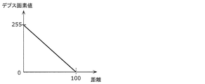
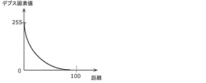
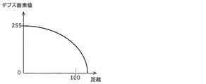
- the 3D model distribution method may further determine a relationship between a pixel value and a distance indicated by the depth image, and distribute information indicating the determined relationship.
- the relationship between the pixel value and the distance can be switched according to the subject or the purpose of use, the accuracy of the restored three-dimensional model can be improved.
- the three-dimensional model includes a first model and a second model having a smaller change per time than the first model
- the depth image includes a first depth image and a second depth image
- the first depth image is generated from the first model
- the second depth image is generated from the second model
- the pixel indicated by the first depth image is determined in the determination of the relationship.
- a first relationship between a value and a distance and a second relationship between a pixel value and a distance indicated by the second depth image are determined, and in the first relationship, the distance resolution in the first distance range is:
- the distance resolution in the second distance range farther than the first distance range may be higher than the distance resolution in the first distance range.
- the distance resolution in the first distance range may be lower than the distance resolution in the second distance range.
- color information is added to the 3D model, and the 3D model distribution method further generates a texture image from the 3D model and compresses the texture image using a 2D image compression method.
- the compressed texture image may be distributed.
- a three-dimensional model receiving method receives a depth image generated from a three-dimensional model and information for restoring the three-dimensional model from the depth image, and uses the information to The three-dimensional model is restored from the depth image.
- the depth image generated from the three-dimensional model is distributed instead of distributing the three-dimensional model as it is. Therefore, the amount of data to be distributed can be suppressed.
- the depth image may be compressed using a two-dimensional image compression method, and the three-dimensional model receiving method may further decode the compressed depth image.
- the data in the distribution of the three-dimensional model, the data can be compressed using the two-dimensional image compression method. Therefore, since it is not necessary to construct a new compression method for the three-dimensional model, the amount of data can be easily reduced.
- a plurality of depth images may be received, and in the decoding, the plurality of depth images may be decoded using a relationship between the plurality of depth images.
- the data amount of a plurality of depth images can be further reduced.
- the three-dimensional model receiving method further generates a rendering image using the three-dimensional model and a plurality of images, and the viewpoint of the depth image is any one of the plurality of images. Also good.
- the disparity information between the captured images is calculated using the depth image.
- the prediction image between the viewpoints can be generated using the parallax information. Thereby, the code amount of the captured image can be reduced.
- the information may include a parameter for projecting the 3D model onto the imaging surface of the depth image, and in the restoration, the 3D model may be restored from the depth image using the parameter.
- the 3D model receiving method may further receive information indicating the bit length of each pixel included in the depth image.
- the bit length can be switched according to the subject or the purpose of use, the data amount can be appropriately reduced.
- the three-dimensional model receiving method may further receive information indicating a relationship between a pixel value and a distance indicated by the depth image.
- the relationship between the pixel value and the distance can be switched according to the subject or the purpose of use, the accuracy of the restored three-dimensional model can be improved.
- the three-dimensional model receiving method further receives a texture image compressed using a two-dimensional image compression method, decodes the compressed texture image, and in the restoration, decodes the decoded depth.
- the three-dimensional model to which color information is added may be restored using the image and the decoded texture image.
- a 3D model distribution apparatus distributes a depth image generation unit that generates a depth image from a 3D model, and the depth image and information for restoring the 3D model from the depth image And a distribution unit.
- the depth image generated from the three-dimensional model is distributed instead of distributing the three-dimensional model as it is. Therefore, the amount of data to be distributed can be suppressed.
- a 3D model receiving apparatus includes a receiving unit that receives a depth image generated from a 3D model, and information for restoring the 3D model from the depth image, and the information And a restoration unit that restores the three-dimensional model from the depth image.
- the depth image generated from the three-dimensional model is distributed instead of distributing the three-dimensional model as it is. Therefore, the amount of data to be distributed can be suppressed.
- FIG. 1 is a diagram showing an outline of a free viewpoint video generation system.
- a 3D space by photographing the same space from multiple viewpoints using a calibrated camera (for example, a fixed camera) (3D space reconstruction).
- a calibrated camera for example, a fixed camera
- 3D space reconstruction By using this three-dimensional reconstructed data for tracking, scene analysis, and video rendering, a video viewed from an arbitrary viewpoint (free viewpoint camera) can be generated. Thereby, a next generation wide area monitoring system and a free viewpoint video generation system can be realized.
- the 3D model generated by the 3D reconstruction is distributed via a network or the like, and the receiving terminal side performs tracking, scene analysis, video rendering, and the like.
- the data amount of the three-dimensional model is enormous, there is a problem that the network bandwidth is insufficient and reception takes time.
- the foreground model and the background model constituting the three-dimensional model are distributed separately by different distribution methods.
- the network bandwidth at the time of distribution can be suppressed by suppressing the number of times of distribution of the background model with a low update frequency. Thereby, the reception time on the terminal side can be shortened.
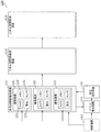
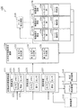
- FIG. 2 is a block diagram illustrating a configuration of the three-dimensional space recognition system 100.
- the three-dimensional space recognition system 100 includes a multi-viewpoint imaging device 111, a control device 112, an event detection device 113, a calibration instruction device 114, a three-dimensional space reconstruction device 115, and a three-dimensional space recognition device 116. Including.
- FIG. 3 is a diagram showing an outline of the operation of the three-dimensional space recognition system 100.
- the multi-view video imaging device 111 generates a multi-view video by shooting the same space (S101).
- camera calibration for estimating the posture (camera parameter) of each camera is performed by manually or automatically detecting the correspondence between the points in the shooting environment and the points on the video and the correspondence between the points on the video (S102). ).
- the three-dimensional space reconstruction device 115 generates a three-dimensional model by performing three-dimensional space reconstruction that three-dimensionally reconstructs the shooting space using the multi-viewpoint video and camera parameters (S103). For example, a foreground model and a background model are generated as a three-dimensional model.
- the 3D space recognition device 116 performs 3D space recognition using the 3D model (S104). Specifically, the three-dimensional space recognition device 116 performs tracking, scene analysis, and video rendering using a three-dimensional model.
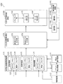
- FIG. 4 is a block diagram showing the configuration of the free viewpoint video generation system 101 according to the present embodiment.
- the free viewpoint video generation system 101 includes a plurality of video display terminals 117 which are user terminals in addition to the configuration of the three-dimensional space recognition system 100.
- the three-dimensional space reconstruction device 115 includes a foreground model generation unit 131 and a background model generation unit 132.
- the three-dimensional space recognition apparatus 116 includes a viewpoint determination unit 141, a rendering unit 142, and a data transfer unit 143.
- FIG. 5 is a diagram showing an outline of the operation of the free viewpoint video generation system 101.
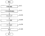
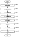
- FIG. 6 is a flowchart showing the operation of the free viewpoint video generation system 101.
- the multi-view video imaging device 111 generates a multi-view video by performing multi-view shooting (S101).
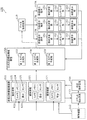
- the multi-view video imaging device 111 includes a plurality of imaging devices 121.
- Each imaging device 121 includes a camera 122, a camera platform 123, a memory 124, and a sensor 125.
- the multi-view video imaging device 111 receives a shooting start or stop signal from the control device 112, and starts or stops shooting synchronized between the imaging devices 121 according to the signal.
- Each imaging device 121 records a time stamp when the image is captured at the same time as the image is captured by the camera 122.
- the imaging device 121 senses a shooting environment using a sensor 125 (vibration sensor, acceleration sensor, geomagnetic sensor, or microphone) simultaneously with shooting, and outputs an image, a time stamp, and sensing data to the event detection device 113.
- a sensor 125 vibration sensor, acceleration sensor, geomagnetic sensor, or microphone
- the multi-view video imaging apparatus 111 receives the calibration instruction information from the calibration instruction apparatus 114, the multi-viewpoint imaging apparatus 111 adjusts the imaging apparatus 121 according to the calibration instruction information, calibrates the camera 122, and sets camera parameters obtained by the calibration to the event detection apparatus 113. Output.
- the memory 124 in each imaging device 121 temporarily stores images, time stamps, sensing data, and camera parameters, and stores shooting settings (such as frame rate and resolution).
- the event detection device 113 includes a video obtained from the multi-view video imaging device 111, a time stamp, sensing information, a three-dimensional model obtained from the three-dimensional space reconstruction device 115, and a free viewpoint obtained from the rendering unit 142.
- a calibration event is detected from at least one of video, terminal information obtained from the video display terminal 117, and control information obtained from the control device 112, and calibration event information including the calibration event is output to the calibration instruction device 114.
- the calibration event information includes information indicating the calibration event, the importance of the calibration event, and the imaging device 121 to be calibrated.
- the calibration event is an opportunity to calibrate the imaging device 121. For example, when a shift of the camera 122 is detected, when a predetermined time is reached, when the accuracy of camera calibration is increased, when the accuracy of a model or free viewpoint video is deteriorated, or when a free viewpoint video is not required When the video of a certain imaging device 121 cannot be used to generate a free viewpoint video, or when there is an instruction from a system administrator or user, the event detection device 113 outputs calibration event information.
- the event detection device 113 detects that the camera 122 has shifted when the sensing information exceeds a threshold, when the background area in the video changes by more than the threshold, or when a cheer is raised.
- the predetermined time is when play is interrupted, such as half time or five times back, when a certain time has elapsed since the last calibration, or when the system is started.
- the case where the accuracy of camera calibration is high is when there are a certain number or more of feature points extracted from the video.
- the event detection device 113 determines the deterioration of the accuracy of the model or the free viewpoint video from the distortion of the wall or the ground in the model or the free viewpoint video.
- the time when the free viewpoint video is not needed is when no video display terminal 117 is used, or when the scene is recognized from sound or video and is identified as not an important scene.
- a video of a certain imaging device 121 cannot be used to generate a free viewpoint video, a sufficient communication band cannot be obtained, a resolution or frame rate of the video is lowered, a synchronization shift occurs, or This is the case when the area captured by the imaging device 121 is not attracting attention for reasons such as no players.
- the importance of the calibration event is calculated from the data observed when the calibration event or the calibration event is detected. For example, a camera shift event is more important than other events. Also, for example, the greater the camera deviation, the higher the importance is set.
- the event detection device 113 may send calibration event information to the video display terminal 117 to notify the user of the imaging device 121 being calibrated.
- the calibration instruction device 114 Upon receiving the calibration event information from the event detection device 113, the calibration instruction device 114 generates calibration instruction information based on the calibration event information, and outputs the generated calibration instruction information to the multi-view video imaging device 111.
- the calibration instruction information includes the camera 122 to be calibrated, the order of the camera 122 to be calibrated, the control information of the camera platform 123, the zoom magnification change information of the camera 122, the calibration method, and the like.
- the control information of the pan head 123 indicates, for example, the amount of rotation of the pan head 123 for returning the camera posture shifted by vibration or the like to the original posture.
- the zoom magnification change information of the camera indicates, for example, a zoom-out amount necessary for covering the shooting area of the camera 122 that is shifted due to vibration or the like.
- the calibration method includes a method of associating a three-dimensional coordinate of a specific point, line or surface with a two-dimensional coordinate on a video, and a two-dimensional coordinate on a video of a specific point, line or surface between two or more images. There is a method of matching. These associations are performed manually, automatically, or both. Further, the accuracy of camera calibration may be improved by using two or more points, lines or planes with known distances, or one or more stereo cameras.
- the 3D space reconstruction device 115 performs 3D space reconstruction using multi-viewpoint images (S103).
- the event detection device 113 includes at least one of video obtained from the multi-view video imaging device 111, time stamp and sensing information, terminal information obtained from the video display terminal 117, and control information obtained from the control device.
- One model generation event is detected, and model generation information including the model generation event is output to the three-dimensional space reconstruction device 115.
- the model generation information includes a model generation event and imaging device information.
- the imaging device information includes video, background images, camera parameters, camera parameter reliability, and camera calibration status.
- a model generation event is a trigger for generating a three-dimensional model of a shooting environment.
- the event detection device 113 outputs model generation information when a predetermined number of cameras are calibrated, when a predetermined time is reached, or when a free viewpoint video is necessary. To do.
- the predetermined time is when a play is being performed or when a certain time has elapsed since the last model generation.
- a free viewpoint video when the video display terminal 117 is used, when a scene is recognized from sound or video and identified as an important scene, or from an instruction from a system administrator or a user When there is a viewing request.
- the reliability of the camera parameters is determined from the result of camera calibration, the time when camera calibration was performed, video, or sensing information. For example, the reliability is set higher as the reprojection error during camera calibration is lower. Further, the higher the reliability is set for the camera that has just been calibrated. In addition, the higher the reliability is set for a camera that has undergone camera calibration using many feature points.
- the 3D space reconstruction device 115 generates a 3D model of the shooting environment using the model generation information obtained from the event detection device 113, and stores the generated 3D model.
- the three-dimensional space reconstruction apparatus 115 preferentially uses a video that has been calibrated and photographed with a high reliability, based on the calibration status of the camera and the reliability of the camera parameters when generating the model. Also, the three-dimensional space reconstruction device 115 outputs model generation completion information to the event detection device 113 when the generation of the three-dimensional model of the shooting environment is completed.
- the 3D space reconstruction device 115 outputs a 3D model of the shooting environment to the rendering unit 142 when the 3D space recognition device 116 which is a free viewpoint image generation device generates a free viewpoint image.
- the foreground model generation unit 131 generates a foreground model that is a foreground model that has a change in movement (a large change) with time, such as a person or a ball.
- the background model generation unit 132 generates a background model that is a background model that does not change in movement (such as little change) at every time such as a venue or a goal.
- the three-dimensional model represents a model including a foreground model and a background model.
- the foreground model generation unit 131 generates a foreground model in accordance with the frame rate recorded by the imaging device 121. For example, when the recording frame rate is 30 frames / second, the foreground model generation unit 131 generates a foreground model every 1/30 seconds.
- the background model generation unit 132 generates a background model using a background image that does not include a foreground, such as a person or a ball, whose movement changes with time.
- the background model generation unit 132 may reuse the once generated background model within a certain period. Further, the background model generation unit 132 may generate a new background model after a certain period of time and update the background model. As a result, it is possible to reduce the amount of processing for generating a background model with little movement, and thus it is possible to reduce the CPU usage rate and the memory amount.
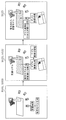
- FIG. 7 is a diagram for explaining this process.
- the background model generation unit 132 generates a background model (S111).
- the multiple imaging devices 121 included in the multi-view video imaging device 111 generate a background image by capturing a background, and record the background image.
- the background model generation unit 132 generates a background model using the background image.
- a background model generation method for example, the three-dimensional position of the object included in the background is specified by calculating the depth of each pixel of the object included in the background image from a plurality of stereo camera pairs as in the multi-view stereo method. Can be used.
- the background model generation unit 132 may use a method of extracting the feature amount of the background image and specifying the three-dimensional position of the feature amount of the background image based on the principle of triangulation from the matching result of the feature amount between the cameras. Absent. Other than this, any method may be used as long as it is a method for calculating a three-dimensional model of an object included in the background.
- the background model may be created manually. For example, it may be possible to generate a three-dimensional model using CG or the like in advance if the shape is determined by a competition such as a goal. That is, the background model generation unit 132 may acquire a background model that is generated in advance.
- the background model generation unit 132 may generate a background image using a plurality of photographed images including the foreground and the background. For example, the background model generation unit 132 may calculate a background image using an average value image of a plurality of captured images. As a result, a background image can be generated even in a situation where a background image that does not include a foreground cannot be captured in advance, and a background model can be generated.
- the plurality of imaging devices 121 included in the multi-view video imaging device 111 generate a captured image by capturing a person (foreground) and a background, and record the captured image (S112).
- the foreground model generation unit 131 generates a foreground model (S113). Specifically, the foreground model generation unit 131 generates a background difference image by subtracting the background image from the captured image of the same viewpoint captured by the same imaging device 121. The foreground model generation unit 131 generates a foreground model using background difference images of a plurality of viewpoints.
- a foreground model generation method for example, a method of specifying a three-dimensional model of a foreground object existing in a space using a plurality of background difference images, such as a visual volume intersection method, can be used.
- the foreground model generation unit 131 extracts the feature amount of the foreground image (background difference image), and specifies the three-dimensional position of the feature amount of the foreground image based on the principle of triangulation from the matching result of the feature amounts between the cameras. May be used. Any other method may be used as long as it is a method for calculating a three-dimensional model of an object included in the foreground.
- the viewpoint determination unit 141 determines a virtual viewpoint (S105).
- the event detection device 113 is a free viewpoint generation event from model generation completion information obtained from the 3D space reconstruction device 115, terminal information obtained from the video display terminal 117, and control information obtained from the control device 112. And the free viewpoint information including the free viewpoint generation event is output to the viewpoint determination unit 141.
- the free viewpoint generation information includes a free viewpoint generation event, a requested viewpoint, and imaging device information.
- the required viewpoint is a viewpoint desired by the user obtained from the video display terminal 117 or a viewpoint designated by the system administrator obtained from the control device.
- the viewpoint may be a single point in a three-dimensional space or a line segment.
- a free viewpoint generation event is an opportunity to generate a free viewpoint video of a shooting environment.
- the event detection device 113 may request a user to view or distribute a free viewpoint video at a time when a 3D model of a shooting environment is generated or when an already generated 3D model exists.
- Free viewpoint information is output when a system administrator gives an instruction.
- the viewpoint determination unit 141 determines a viewpoint at the time of generating a free viewpoint video based on the free viewpoint information obtained from the event detection device 113, and outputs the viewpoint to the rendering unit 142 together with the free viewpoint information.
- the viewpoint determination unit 141 performs viewpoint determination based on the requested viewpoint. If there is no required viewpoint, the viewpoint determination unit 141 may automatically detect a viewpoint or the like from which the player can be seen from the front, or has been calibrated from the reliability of the camera parameters or the camera calibration status. In addition, a viewpoint that is close to the imaging device 121 with high reliability may be automatically detected.
- the structure and distance information of the shooting environment seen from the virtual viewpoint is determined from the three-dimensional model (including the foreground model and the background model).
- the rendering unit 142 performs rendering using the three-dimensional model, thereby generating a free viewpoint video that is a video viewed from a virtual viewpoint (S106).
- the rendering unit 142 uses the viewpoint information and free viewpoint information obtained from the viewpoint determination unit 141 and the three-dimensional model of the shooting environment obtained from the three-dimensional space reconstruction device 115 to follow the viewpoint information.
- the viewpoint video is generated, and the generated video is output to the data transfer unit 143 as a free viewpoint video.
- the rendering unit 142 generates a free viewpoint video by projecting the three-dimensional model to the virtual viewpoint position indicated by the viewpoint information.
- the rendering unit 142 preferentially acquires color and texture information on the video from, for example, a video obtained by the imaging device 121 that is close to the virtual viewpoint position.
- the rendering unit 142 preferentially performs color information from the video of the imaging device 121 different from the imaging device 121 with a short distance.
- the rendering unit 142 calibrates the image quality by blurring the video or increasing the playback speed when the imaging device 121 close to the virtual viewpoint position is being calibrated or when the reliability of the camera parameter is low. It may be difficult to make the user aware of the decrease. As described above, the rendering unit 142 does not necessarily need to preferentially acquire from the video of the imaging device 121 that is close to the distance, and may use any technique to acquire the color and texture on the video. Further, color information may be added in advance to the three-dimensional model itself.
- the data transfer unit 143 distributes the free viewpoint video obtained from the rendering unit 142 to the video display terminal 117 (S107).
- the data transfer unit 143 may distribute different free viewpoint videos for each video display terminal 117 based on the viewpoint requested by each user, or the viewpoint or viewpoint determination unit 141 specified by the system administrator automatically determines.
- the same free viewpoint video generated based on the selected viewpoint may be distributed to a plurality of video display terminals 117.
- the data transfer unit 143 may compress the free viewpoint video and distribute the compressed free viewpoint video.
- each video display terminal 117 displays the distributed free viewpoint video (S108).
- the video display terminal 117 includes a display, a wireless communication device, and a user input interface.
- the user uses the video display terminal 117 to send a viewing request to the event detection device 113 for viewing an arbitrary area at an arbitrary time in the shooting environment from an arbitrary viewpoint.
- the video display terminal 117 receives a free viewpoint video based on the viewing request from the data transfer unit 143 and displays it to the user.
- the video display terminal 117 receives the calibration event information obtained from the event detection device 113, and highlights the camera being calibrated on the display. Thereby, it is possible to notify the user that a free viewpoint video from a viewpoint near the imaging apparatus cannot be generated or the image quality is deteriorated.
- the system administrator sends a shooting start or stop signal from the control device 112 to the multi-view video imaging device 111, and causes the multi-view video imaging device 111 to start or stop synchronous shooting.
- control information can be sent from the control device 112 to the event detection device 113 to calibrate any camera.
- control information is sent from the control device 112 to the event detection device 113, and the three-dimensional shooting environment at any time using any image pickup device 121.
- a model can be generated.
- control information can be sent from the control device 112 to the event detection device 113 to generate a free viewpoint video at an arbitrary time and distribute it to the video display terminal 117. it can.
- Embodiment 2 The function of free viewpoint video generation described above may be used in a monitoring system. In this case, the estimated appearance of the suspicious person viewed from a viewpoint that is not captured by the actual camera can be presented to the security guard to be alerted.
- FIG. 8 is a block diagram showing a configuration of the next generation monitoring system 102 according to the present embodiment.
- the next-generation monitoring system 102 shown in FIG. 8 differs from the free viewpoint video generation system 101 shown in FIG. 4 in the configuration of the three-dimensional space recognition device 116A.
- the next-generation monitoring system 102 includes a monitor 118A, a guard 118B, and a video imaging device 118C instead of the video display terminal 117.
- the three-dimensional space recognition device 116A includes a tracking unit 144, a scene analysis unit 145, and a data transfer unit 146.
- FIG. 9 is a diagram showing an outline of the operation of the next generation monitoring system 102.
- FIG. 10 is a flowchart showing the operation of the next generation monitoring system 102. Note that multi-view shooting (S101), camera calibration (S102), and three-dimensional space reconstruction (S103) are the same as in FIGS.
- the 3D space recognition device 116A performs 3D space recognition using a 3D model (S104B). Specifically, the tracking unit 144 tracks a person in a three-dimensional space (S105B). In addition, the tracking unit 144 automatically extracts an image in which a person is captured.
- the scene analysis unit 145 performs scene analysis (S106B). Specifically, the scene analysis unit 145 performs situation recognition and abnormality detection of a person or a scene from a three-dimensional space or multi-view video.
- the data transfer unit 146 transfers the result of the three-dimensional space recognition to the terminal or the like possessed by the supervisor 118A or the guard 118B, or the video imaging device 118C (S107B). Then, the result of the three-dimensional space recognition is displayed on a terminal or the like possessed by the supervisor 118A or the guard 118B, or on a display unit provided in the video imaging device 118C (S108B).
- the scene analysis unit 145 and the tracking unit 144 are similar to the generation of the free viewpoint video, based on the three-dimensional model generated by the three-dimensional space reconstruction device 115, the structure viewed from the virtual viewpoint of each subject in the shooting region, And the distance from the virtual viewpoint. Further, the scene analysis unit 145 and the tracking unit 144 can preferentially acquire the color and texture of each subject from the video of the imaging device 121 at a short distance from the virtual viewpoint, and can use the acquired information.
- Scene analysis using a two-dimensional image is executed by analyzing each object in the photographing region, for example, an image showing a certain moment of a person or an object with software or a person on the screen. Since the scene analysis unit 145 performs the scene analysis based on the three-dimensional model data, it is possible to observe the three-dimensional posture of the person or the three-dimensional shape of the object in the imaging region. Highly accurate situation recognition and prediction are possible.
- a subject in a shooting area is specified by scene analysis of a video shot by the imaging device 121.
- the same subject specified on the video captured by the imaging device 121 at different moments is associated with the software or manually.
- tracking is executed by specifying and associating such a subject along the time axis.
- the subject of interest may be temporarily hidden behind another subject, so that the specific continuation of the subject may not be possible. Even in such a case, the identification of the subject can be continued using the 3D position information or the 3D shape information of each subject by using the 3D model.
- the next-generation monitoring system 102 uses the scene analysis and tracking functions using such a three-dimensional model. As a result, early detection of a suspicious site and improvement in detection accuracy can be realized. Further, even in a place where the number of cameras that can be installed is limited, it is possible to enhance security as compared with the case where two-dimensional video is used.
- the scene analysis unit 145 analyzes the data of the three-dimensional model and identifies, for example, a subject.
- the result of the analysis may be passed to the tracking unit 144 or displayed on a display such as a terminal together with the free viewpoint video.
- the analysis result data of the free viewpoint video may be stored in a storage device included in the terminal or the like or an external storage device. Further, depending on the result of the analysis, determination of a virtual viewpoint at another time or another position may be requested from the scene analysis unit 145 to the user via the terminal.
- the tracking unit 144 tracks a specific subject based on the three-dimensional model data.
- the tracking result may be displayed on a display such as a terminal together with the free viewpoint video. For example, when tracking of a specific subject is impossible, determination of a virtual viewpoint at another time or another position may be requested from the tracking unit 144 to the user via the terminal.
- FIG. 11 is a block diagram showing a configuration of free viewpoint video generation system 103 according to the present embodiment.
- the free viewpoint video generation system 103 shown in FIG. 11 is different from the free viewpoint video generation system 101 shown in FIG. 4 in that a viewpoint determination unit 151 and a rendering unit 152 are provided in the video display terminal 117A.
- the data transfer device 119 distributes the 3D model (foreground model and background model) generated by the 3D space reconstruction device 115 to the video display terminal 117A. Note that the data transfer device 119 may further transmit the captured video and camera parameters obtained by the multi-view video imaging device 111 to the video display terminal 117A.
- the 3D space reconstruction device 115 adds color information to the 3D model using a captured image or the like when generating the 3D model, and the data transfer device 119 stores the color information in the video display terminal 117A.
- the added 3D model may be distributed. In this case, the data transfer device 119 may not distribute the captured video to the video display terminal 117A.
- the video display terminal 117A includes a display, a wireless communication device, and a user input interface.
- the user uses the video display terminal 117A to send a viewing request to view an arbitrary area at an arbitrary time in the shooting environment to the event detection device 113, and data transfer of the 3D model, the shot video, and the camera parameters based on the viewing request Receive from device 119.
- the video display terminal 117A generates a viewpoint video according to the viewpoint information using the viewpoint information designated by the user to be viewed and the received three-dimensional model, and outputs the generated video to the display as a free viewpoint video. To do.
- FIG. 12 is a flowchart showing the operation of the free viewpoint video generation system 103. Steps S101 and S103 are the same as those in the first embodiment shown in FIG.
- the data transfer device 119 delivers the three-dimensional model (foreground model and background model) generated by the three-dimensional space reconstruction device 115 to the video display terminal 117A (S107C). At this time, the data transfer device 119 distributes the foreground model and the background model using different distribution methods.
- the data transfer device 119 distributes the three-dimensional model to the video display terminal 117A, the foreground model and the background model are distributed separately. At that time, for example, the data transfer device 119 adds a flag or an identifier for distinguishing whether each model is a foreground model or a background model to header information included in the distribution data.
- the delivery cycle of the foreground model and the background model may be different.
- the foreground model delivery cycle may be less than the background model delivery cycle.
- the data transfer device 119 delivers the foreground model at 30 models / second in accordance with the recording frame rate of the imaging device 121.
- the data transfer device 119 distributes one model as a background model, for example.
- the data transfer device 119 may generate a difference model that is a difference between the foreground model at the current time and the foreground model at the previous time, and distribute the generated difference model. Further, the data transfer device 119 predicts the motion of the foreground model, generates a prediction model from the foreground model at the previous time, generates a difference model that is a difference between the foreground model at the current time and the prediction model, and generates the generated difference The model and motion information indicating the result of motion prediction may be distributed. As a result, the information amount of the foreground model can be reduced, so that the network bandwidth can be suppressed. Further, the data transfer device 119 may compress the information amount of the transmission data by performing variable length coding or arithmetic coding on the difference model and the motion information.
- the data transfer device 119 may distribute one background model when the user starts viewing. Alternatively, the data transfer device 119 may transmit the background model at predetermined intervals. At this time, the data transfer device 119 may generate a difference model that is a difference between the current background model and the background model distributed last time, and transmit the generated difference model. As a result, the information amount of the background model to be distributed can be reduced, and the network bandwidth can be suppressed.
- the data transfer device 119 may transmit both the foreground model and the background model at the random access point.
- the video display terminal 117A can always generate a free viewpoint video using an appropriate foreground model and background model when the user switches the time to view.
- FIG. 13 is a diagram showing an example of distribution of the foreground model and the background model when one background model is distributed when the user starts viewing.
- the data transfer device 119 distributes one background model when the user starts viewing.
- the video display terminal 117A generates a free viewpoint video using the background model and the foreground model received at each time.
- FIG. 14 is a diagram illustrating a distribution example of the foreground model and the background model when the background model is distributed at regular intervals.
- the data transfer device 119 distributes the background model at predetermined intervals.
- the predetermined interval is longer than the distribution interval of the foreground model.
- the video display terminal 117A generates a free viewpoint video using the background model received immediately before and the foreground model received every time.
- the data transfer device 119 may switch the encoding method for each model when the foreground model and the background model are encoded and distributed. That is, the data transfer device 119 may use different encoding methods for the foreground model and the background model. For example, for the foreground model, the data transfer device 119 applies an encoding method that prioritizes low delay for the purpose of immediate reproduction on the video display terminal 117A side. In addition, the data transfer device 119 applies a coding method giving priority to high efficiency to the background model in order to reduce the amount of information as much as possible. Thus, by selecting an appropriate encoding method according to the usage application of each model, it is possible to improve the functionality of the system while reducing the amount of data.
- the data transfer apparatus 119 may use a highly efficient encoding method for the foreground model and may use an encoding method that is less efficient than the foreground model for the background model. For example, since the background model is less frequently distributed, the network load is unlikely to increase even if the amount of data increases by using a low-efficiency encoding method. On the other hand, the processing load on the background model in the server or terminal can be suppressed by using a low-efficiency encoding method that is light in processing. In addition, the foreground model is frequently updated. Therefore, even if the processing load on the server or terminal is high, the network load can be reduced by encoding the foreground model as efficiently as possible. Note that the data transfer device 119 may send the model as it is without performing encoding, instead of performing a low-efficiency encoding method.
- the data transfer device 119 may distribute the foreground model and the background model using a network or protocol having different characteristics.
- the data transfer device 119 is intended for immediate playback on the video display terminal 117A side, uses a high-speed network with low packet loss and high reliability, UDP (User Datagram Protocol), etc. The low-latency delivery protocol is used.
- the data transfer device 119 uses a low-speed network and ensures error tolerance such as TCP (Transmission Control Protocol) in order to reliably distribute the background model while ensuring the transmission bandwidth of the foreground model. Use a higher protocol.
- download distribution using HTTP (Hypertext Transfer Protocol) etc. is applied to the background model
- stream distribution using RTP (Real-time Transport Protocol) etc. is applied to the foreground model, thereby reducing the foreground model. Delay may be realized.
- the data transfer device 119 may acquire the viewpoint position information that the user is viewing from the video display terminal 117A, and switch the 3D model to be distributed using the information.
- the data transfer device 119 may preferentially distribute the foreground model and the background model necessary for generating a video viewed from the viewpoint that the user is viewing.
- the data transfer device 119 distributes the foreground model necessary for generating the video viewed from the viewpoint the user is viewing with high accuracy (high density), and performs a thinning process or the like on the other models. May be delivered with reduced accuracy (density). Thereby, the amount of distribution data can be reduced.
- the background model need not be switched.
- the data transfer device 119 may change the density or distribution cycle of the three-dimensional model to be distributed according to the available network bandwidth. For example, the data transfer device 119 may decrease the density of the three-dimensional model or increase the distribution cycle as the network bandwidth is narrower. Further, the video display terminal 117A may switch the rendering resolution in accordance with the density of the three-dimensional model distributed by the data transfer device 119. For example, when the network bandwidth is narrow, the data transfer device 119 distributes the density of the three-dimensional model with sparseness by thinning processing or the like. In addition, the video display terminal 117A displays a video with a reduced rendering resolution.
- the data transfer device 119 distributes important subjects using a dense three-dimensional model and distributes other subjects using a sparse three-dimensional model. As a result, the amount of distribution data can be reduced while maintaining the image quality of important subjects. Further, when the network band becomes narrow, the data transfer device 119 may reduce the temporal resolution of the three-dimensional model to be distributed, for example, by extending the distribution period of the foreground model.
- the video display terminal 117A performs three-dimensional space recognition using the distributed three-dimensional model.
- the viewpoint determination unit 151 determines a virtual viewpoint (S105C).
- the rendering unit 152 generates a free viewpoint video that is a video viewed from a virtual viewpoint by performing rendering using the three-dimensional model (S106C). These processes are the same as the processes in steps S105 and S106 in the first embodiment.
- the video display unit 153 displays the generated free viewpoint video (S108C).
- the video display terminal 117A may receive the foreground model and the background model separately when receiving the three-dimensional model from the data transfer device 119. At that time, the video display terminal 117A may acquire a flag or an identifier for distinguishing whether each model is a foreground model or a background model by analyzing header information or the like.
- the reception cycle of the foreground model and the background model may be different. Further, the reception period of the foreground model may be less than the reception period of the background model. For example, when the recording frame rate of the imaging device 121 is 30 frames / second, the video display terminal 117A receives the foreground model at 30 models / second in accordance with the recording frame rate of the imaging device 121. The video display terminal 117A receives one model as a background model.
- the video display terminal 117A When receiving the foreground model, the video display terminal 117A receives a difference model that is a difference between the foreground model at the current time and the foreground model at the previous time, and adds the foreground model and the difference model at the previous time. A foreground model of time may be generated.
- the video display terminal 117A receives the difference model and motion information indicating the result of motion prediction, generates a prediction model from the received motion information and the foreground model at the previous time, and adds the difference model and the prediction model. By doing so, a foreground model at the current time may be generated. As a result, the amount of information of the foreground model received can be reduced, so that the network bandwidth can be suppressed.
- the video display terminal 117A performs variable length decoding or arithmetic decoding of the received data to obtain the difference model and motion information. You may decode.
- the video display terminal 117A may receive one background model at the start of viewing by the user and use one background model at all times. Alternatively, the video display terminal 117A may receive the background model at predetermined intervals. At this time, the video display terminal 117 receives a difference model that is a difference between the background model received last time and the current background model, and generates the current background model by adding the previous background model and the difference model. May be. Thereby, the amount of information of the received background model can be reduced, so that the network bandwidth can be suppressed.
- the video display terminal 117A may receive both the foreground model and the background model at the random access point.
- the video display terminal 117A can always generate a free viewpoint video using an appropriate foreground model and background model when the user switches the time to view.
- the video display terminal 117A may perform rendering processing using the already received 3D model. For example, if the foreground model cannot be received, the video display terminal 117A may generate a prediction model by predicting motion from the already received foreground model, and use the generated prediction model as the foreground model at the current time. If the video display terminal 117A cannot receive the background model, the video display terminal 117A may use the already received background model or the CG model. In addition, when the video display terminal 117A cannot receive the background model or the foreground model, it may use a model or rendering image prepared in advance, such as a CG image. Thereby, even when the three-dimensional model cannot be received, the video display terminal 117A can provide the rendering image to the user.
- a model or rendering image prepared in advance such as a CG image.
- the data transfer device 119 also includes camera parameters, captured images obtained by the multi-view image capturing device 111, background images, background difference images, time information when each captured image or 3D model is generated, and viewpoint position at the start of rendering. At least one of the information and the time information for rendering may be distributed to the video display terminal 117A.
- the data transfer device 119 may distribute the camera parameters to the video display terminal 117A only at the start of viewing. Further, the data transfer device 119 may distribute the camera parameters to the video display terminal 117A at the timing when the calibration is performed by the calibration instruction device 114. When the imaging device 121 is not fixed, the data transfer device 119 may distribute the camera parameter to the video display terminal 117A every time the camera parameter is updated.
- the data transfer device 119 may distribute the captured video, background image, or background difference image obtained by the multi-view video imaging device 111 after encoding. Thereby, the data amount of transmission data can be reduced.
- the data transfer device 119 uses the correlation between multi-viewpoint images. H.264 or H.264 265 multi-view codec (MVC) may be used.
- MVC multi-view codec
- the data transfer device 119 independently converts the video of each imaging device 121 to H.264. H.264 or H.264 The data may be distributed after being encoded by H.265. As a result, the amount of data distributed to the video display terminal 117A can be reduced.
- the viewpoint position information at the start of rendering may be specified by the user via the video display terminal 117A at the start.
- the viewpoint determination unit 151 may switch the viewpoint position depending on the viewing style using the video display terminal 117A or the type of the video display terminal 117A. For example, in the case of viewing on television, the viewpoint determination unit 151 includes a recommended viewpoint specified by the system side, a viewpoint from the imaging apparatus 121 close to the ball, a viewpoint from the imaging apparatus 121 capturing the center of the field, Alternatively, a viewpoint with a high audience rating is determined as the starting viewpoint.
- the viewpoint determination unit 151 determines a viewpoint or the like in which the user's favorite player is captured as a starting viewpoint. Further, in the case of viewing on a head-out display, the viewpoint determination unit 151 determines a recommended viewpoint for VR (Virtual Reality), for example, a player viewpoint on the field or a viewpoint from a bench as a starting viewpoint. .
- VR Virtual Reality
- FIG. 15 is a block diagram showing a configuration of the next generation monitoring system 104 according to the present embodiment.
- the next generation monitoring system 104 shown in FIG. 15 differs from the next generation monitoring system 102 shown in FIG. 8 in that a tracking unit 154 and a scene analysis unit 155 are provided in the video display terminal 117B.
- FIG. 16 is a flowchart showing the operation of the next generation monitoring system 104. Steps S101, S103, and S107C are the same as those in the third embodiment shown in FIG.
- the video display terminal 117B performs three-dimensional space recognition using a three-dimensional model. Specifically, the tracking unit 154 tracks a person in a three-dimensional space (S105D). The scene analysis unit 155 performs scene analysis (S106D). Then, the video display terminal 117B displays the result of the three-dimensional space recognition (S108D). These processes are the same as the processes in steps S105B, S106B, and S108B in the second embodiment.
- FIG. 17 is a block diagram showing a configuration of the free viewpoint video generation system 105 according to the present embodiment.
- a free viewpoint video generation system 105 shown in FIG. 17 differs from the free viewpoint video generation system 103 shown in FIG. 11 in the configuration of a three-dimensional space reconstruction device 115A.
- the three-dimensional space reconstruction device 115A includes a first model generation unit 133 that generates a first model, a second model generation unit 134 that generates a second model, and a third model generation unit 135 that generates a third model.
- the three-dimensional space reconstruction device 115A generates a three-dimensional model including the first model, the second model, and the third model.
- the data transfer device 119 distributes the first to third models to the video display terminal 117A separately by different distribution methods.
- the three-dimensional space reconstruction device 115A updates each model at a different frequency.
- the data transfer device 119 delivers each model to the video display terminal 117A at different periods.
- the first model is a foreground model
- the second model is a part of the background model
- the third model is a background model other than the second model.
- the data transfer device 119 delivers the first model at 30 models / second in accordance with the recording frame rate of the imaging device 121.
- the data transfer device 119 distributes the second model at 1 model / second, and distributes one model as the third model at the start of viewing.
- the data transfer device 119 may add an identifier for identifying two or more models to the three-dimensional model. Accordingly, the video display terminal 117A can determine which model the received three-dimensional model corresponds to by analyzing the identifier.
- the two models may be other than the foreground model and the background model.
- the three-dimensional data may include a first model with a high update frequency and a large amount of data, and a second model with a low update frequency and a small amount of data.
- the data transfer device 119 may distribute each model to the video display terminal 117A separately by a different distribution method. At this time, since the update frequency is different for each model, the data transfer device 119 delivers each model to the video display terminal 117A at different periods. For example, when the recording frame rate of the imaging device 121 is 30 frames / second, the data transfer device 119 delivers the first model at 30 models / second in accordance with the recording frame rate of the imaging device 121. The data transfer device 119 distributes one model as the second model at the start of viewing. As a result, three-dimensional models with different data amounts can be distributed at different periods, so that the network bandwidth can be suppressed.
- the first model and the second model may be models having different importance levels.
- the data transfer device 119 may distribute each model to the video display terminal 117A separately by a different distribution method. At this time, since the importance is different for each model, the data transfer device 119 distributes each model to the video display terminal 117A at different periods. For example, it is assumed that the first model is a high importance model and the second model is a low importance model. In this case, when the recording frame rate of the imaging device 121 is 30 frames / second, the data transfer device 119 delivers the first model at 30 models / second according to the recording frame rate of the imaging device 121, and the first Deliver 2 models at 15 models / second. As a result, it is possible to preferentially distribute a three-dimensional model with high importance, and it is possible to provide an appropriate rendered image to a user who uses the image display terminal 117A while suppressing the network bandwidth.
- the data transfer device 119 may switch other than the distribution cycle depending on the importance. For example, the data transfer device 119 may switch the model density according to the priority. For example, when the data transfer device 119 distributes a three-dimensional model in a soccer game, the data transfer device 119 determines that the three-dimensional model of the player competing in front of one goal is high in importance, and the goal near the other goal The keeper's 3D model is judged to be less important. Then, the data transfer device 119 distributes the density of the goalkeeper's 3D model lower than that of the highly important 3D model. Note that the data transfer device 119 does not have to distribute a three-dimensional model with low importance.
- the data transfer device 119 determines whether the degree of importance is high or low, for example, whether a model to be determined is close to a specific feature point or target object such as a ball, or a viewpoint that viewers often see. This is based on whether it is close to the position. For example, the importance level of a model close to a specific feature point or object is high, and the importance level of a model close to a viewpoint position often viewed by viewers is set high.
- Each model may be a set of one or more objects (for example, a person, a ball, a car, etc.) determined by object recognition or the like, or an area determined based on movement, such as the background and foreground. Or it may be a set of objects.
- objects for example, a person, a ball, a car, etc.
- FIG. 18 is a block diagram showing a configuration of the next generation monitoring system 106 according to the present embodiment.
- the next generation monitoring system 106 shown in FIG. 18 differs from the next generation monitoring system 104 shown in FIG. 15 in the configuration of the three-dimensional space reconstruction device 115A.
- the functions and the like of the three-dimensional space reconstruction device 115A are the same as those in FIG.
- the three-dimensional model distribution device uses the first model (for example, the foreground model) that is the three-dimensional model of the target space in the target time zone as the first model.
- a second distribution different from the first distribution method is a second model (for example, a background model) that is distributed in one distribution method and is a three-dimensional model of the target space in the target time zone and has a smaller change per time than the first model. Deliver in the form. That is, the 3D model distribution apparatus transmits the foreground model and the background model separately.
- the transmission cycle of the first model and the second model is different.
- the delivery cycle of the first delivery method is shorter than the delivery cycle of the second delivery method.
- the 3D model distribution apparatus transmits the first model at predetermined intervals.
- the 3D model distribution apparatus may transmit a difference model that is a difference between the first model at the current time and the first model at the previous time.
- the three-dimensional model distribution apparatus may transmit motion information from the first model at the previous time of the first model at the current time.
- the 3D model distribution device transmits the second model at the start of viewing.
- the three-dimensional model distribution device transmits the second model at predetermined intervals.
- the three-dimensional model distribution device may transmit a difference model that is a difference between the current second model and the previously transmitted second model.
- the 3D model distribution apparatus may transmit the second model for each random access point.
- the 3D model distribution apparatus may transmit information such as a flag for distinguishing whether each model is the first model or the second model.
- the 3D model distribution apparatus may transmit both the first model and the second model at the random access point.
- the 3D model distribution apparatus may generate the first model and the second model by different methods. Specifically, the three-dimensional model distribution device generates the first model by the first generation method, and generates the second model by the second generation method that is different in accuracy from the first generation method. For example, the three-dimensional model distribution device generates the first model by the first generation method, and generates the second model by the second generation method with higher accuracy than the first generation method. Alternatively, the three-dimensional model distribution device generates the first model by the first generation method, and generates the second model by the second generation method that is less accurate than the first generation method.
- the 3D model distribution apparatus when it is necessary to render a first model (foreground model) such as a player or a criminal with as high image quality as possible, the 3D model distribution apparatus generates the first model with high accuracy even if the amount of data increases. On the other hand, the 3D model distribution apparatus suppresses the data amount by reducing the accuracy of the second model in a region that is less important than the foreground, such as a spectator or a background image.
- the 3D model distribution device includes a third model that is a 3D model of a plurality of objects included in the target space in the target time zone, and one of the plurality of objects included in the target space in the target time zone.
- a first model (foreground model) that is a difference between the third model and the second model is generated from a second model (background model) that is a three-dimensional model of the target object.
- the 3D model distribution apparatus includes a first multi-viewpoint image (captured image) obtained by capturing a plurality of objects included in a target space in a target time zone, and a part of the plurality of objects.
- a third multi-viewpoint image (background differential image) that is a difference from the second multi-viewpoint image (background image) in which is taken is generated, and the first model (background differential image) is used to generate the first model (background differential image).
- background differential image background differential image
- the 3D model distribution device generates the first model by the visual volume intersection method using the second multi-viewpoint image (captured image) or the third multi-viewpoint image (background difference image), and the second model is generated.
- the processing amount for generating the first model can be reduced, and the accuracy of the second model can be improved.
- the 3D model distribution apparatus may manually create the second model.
- the 3D model distribution device may distribute data other than the 3D model.
- the data other than the three-dimensional model includes at least one of a camera parameter, a multi-viewpoint image, a background difference image, time information, and a starting viewpoint position.
- the 3D model distribution apparatus may distribute the camera parameters of the fixed camera at the start of viewing and distribute the camera parameters of the non-fixed camera every time the camera parameter changes.
- the viewpoint position at the start of viewing may be specified by the user at the start of viewing.
- the viewpoint position at the start of viewing may be switched depending on the viewing style or the type of terminal. For example, in the case of viewing on television, a recommended viewpoint, one of fixed cameras (for example, close to the ball or the center of the field), or a viewpoint with a high audience rating is selected. In the case of viewing on a personal tablet terminal or smartphone, the viewpoint where the favorite player appears is selected. In addition, when viewing on a head mounted display, a recommended viewpoint for VR (for example, a viewpoint on the field) is selected.
- the first model and the second model are not limited to the two models of the foreground model and the background model. Two or more models may be generated and distributed separately by different distribution methods. In this case, since the update frequency varies from model to model (the update frequency varies depending on the region even in the background), the three-dimensional model distribution apparatus distributes each model at different periods. The 3D model distribution apparatus adds an identifier for identifying two or more models.
- the 3D model distribution device switches the encoding method for each model.
- the first encoding method is used in the first delivery method used for the first model.
- the second encoding method is used in the second distribution method used for the second model.
- the first coding method and the second coding method differ in at least one of processing delay and coding efficiency.
- the second encoding scheme has a larger processing delay than the first encoding scheme.
- the second encoding scheme has higher encoding efficiency than the first encoding scheme.
- the second encoding scheme has lower encoding efficiency than the first encoding scheme.
- the first delivery method may have a lower delay than the second delivery method.
- the three-dimensional model distribution apparatus distributes the first model with low delay using a highly reliable line (for example, using UDP).
- the 3D model distribution apparatus distributes the second model via a low-speed line (for example, using TCP).
- the 3D model distribution apparatus may download and distribute the second model (for example, HTTP) and perform stream distribution (for example, RTP) of the first model.
- the 3D model receiving apparatus for example, the video display terminal 117A
- the already received 3D model may be used.
- the prediction model is generated by predicting the motion from the already received first model, and the generated prediction model is used as the first model at the current time. Use.
- the 3D model receiving apparatus when the 3D model receiving apparatus cannot receive the second model, it uses the already received second model.
- the three-dimensional model receiving apparatus uses a model or rendering image prepared in advance, such as a CG model or a CG image. That is, the three-dimensional model receiving apparatus may perform different error concealment processes for the first model and the second model.
- the 3D model distribution apparatus may distribute the first model and the second model necessary for generating the video of the viewpoint viewed by the user with priority.
- the 3D model distribution apparatus may distribute the first model necessary for generating the video of the viewpoint viewed by the user with high accuracy and thin out the other first models.
- the terminal to which the first model and the second model are distributed (for example, the video display terminal 117A) uses the first model and the second model to generate a free viewpoint video that is a video viewed from the selected viewpoint.
- the three-dimensional model distribution device distributes a model necessary for generating a free viewpoint video with priority among the first models.
- the 3D model distribution device may change the quality of the 3D model distributed according to the available network bandwidth.
- the 3D model distribution apparatus switches the density or rendering resolution of the 3D model according to the network bandwidth.
- the 3D model distribution apparatus reduces the rendering resolution by reducing the density of the 3D model.
- the density switching of the three-dimensional model can be performed by a method such as uniform thinning or switching according to the target object.
- the 3D model distribution apparatus performs a process of reducing the temporal resolution of the 3D model to be distributed, such as extending the distribution period of the first model.
- a three-dimensional model is generated using a multi-view video obtained by the multi-view video imaging device 111
- a method for generating a three-dimensional model is described above. It is not limited to.
- the three-dimensional model may be generated using information obtained by means other than the camera, such as LIDAR (Light Detection and Ranging) or TOF (Time of Flight).
- a multi-view video used for generating a three-dimensional model may be generated using these pieces of information.
- the 3D model may be in any form as long as it is information representing the 3D position of the target object.
- the 3D model may be in the form of a point cloud, voxel, mesh, polygon, or depth information.
- the three-dimensional space reconstruction device 115C generates one or more depth images from the three-dimensional model, compresses the generated depth images, and distributes them to the video display terminal 117C.
- the video display terminal 117C restores the three-dimensional model from the received depth image.
- the network band at the time of delivery can be suppressed by efficiently compressing and delivering the depth image.
- FIG. 19 is a block diagram showing a configuration of the free viewpoint video generation system 107 according to the present embodiment.
- a free viewpoint video generation system 107 shown in FIG. 19 differs from the free viewpoint video generation system 105 shown in FIG. 17 in the configurations of a three-dimensional space reconstruction device 115C, a data transfer device 119C, and a video display terminal 117C.
- the three-dimensional space reconstruction device 115C includes a first depth image generation unit 136, a second depth image generation unit 137, and a third depth image generation unit 138 in addition to the configuration of the three-dimensional space reconstruction device 115A.
- the video display terminal 117C includes a model restoration unit 156 in addition to the configuration of the video display terminal 117A.
- the 3D space reconstruction device 115C generates one or more depth images (distance images) from the created 3D model instead of distributing the 3D model.
- the data transfer device 119C distributes the generated one or more depth images to the video display terminal 117C.
- the video display terminal 117C receives one or more depth images, restores (generates) a three-dimensional model, and generates a rendering image using the restored three-dimensional model and the received captured image.
- FIG. 20 is a flowchart showing the operation of the free viewpoint video generation system 107.
- the process shown in FIG. 20 includes steps S121 to S123 instead of step S107C with respect to the process shown in FIG.
- Steps S101 and S103 are the same as in the fifth embodiment, and the first model, the second model, and the third model are generated by the first model generation unit 133, the second model generation unit 134, and the third model generation unit 135. .
- the first depth image generation unit 136 generates one or more first depth images from the first model
- the second depth image generation unit 137 generates one or more second depth images from the second model
- the third depth image generation unit 138 generates one or more third depth images from the third model (S121).
- the data transfer device 119C reduces the data amount of these depth images by performing two-dimensional image compression processing or the like on the generated first depth image, second depth image, and third depth image. Then, the data transfer device 119C delivers the compressed first depth image, second depth image, and third depth image to the video display terminal 117C (S122).
- the model restoration unit 156 of the video display terminal 117C decodes the received first depth image, second depth image, and third depth image, and restores (generates) the first model using the first depth image. Then, the second model is restored (generated) using the second depth image, and the third model is restored (generated) using the third depth image (S123).
- the viewpoint determination unit 151 determines the viewpoint that the user wants to see (S105C).
- the rendering unit 152 generates a rendered image that is an image viewed from the determined viewpoint, using the restored first to third models and the received captured image (S106C).
- the video display unit 153 displays the rendered image (S108C).
- the data transfer device 119C delivers a depth image that is a two-dimensional image instead of delivering a three-dimensional model.
- the data transfer device 119C can H.264 or H.264 Since the depth image can be compressed and transmitted using a standard image compression method such as H.265, the data transfer amount can be suppressed.
- the first to third models may be composed of point clouds (point clouds), meshes, or polygons.
- the case where the first to third models are generated has been described as an example.
- the foreground model and the background model are generated.
- the same technique can be applied to such cases.
- a similar method can also be applied when generating a single three-dimensional model.
- the free viewpoint video generation system has been described as an example, but the same technique can be applied to a next-generation monitoring system.
- the three-dimensional space reconstruction device 115C may distribute camera parameters corresponding to the depth image.
- this camera parameter is a camera parameter at the viewpoint of the depth image.
- the camera parameters include internal parameters indicating the camera focal length, image center, and the like, and external parameters indicating the camera posture (three-dimensional position and orientation) and the like.
- the 3D space reconstruction device 115C generates a depth image from the 3D model using the camera parameters.
- the information to be transmitted is not limited to camera parameters, but may be any parameters used when generating a depth image from a three-dimensional model. That is, the parameter may be a parameter for projecting a three-dimensional model onto a predetermined viewpoint (depth image viewpoint) imaging plane.
- the parameter may be a projection matrix calculated using camera parameters.
- the video display terminal 117C generates a three-dimensional model by projecting each pixel of one or more depth images onto a three-dimensional space using the received camera parameters.
- the three-dimensional space reconstruction device 115C may generate a plurality of depth images obtained by projecting the three-dimensional model on the same plane as the imaging surface of each imaging device 121.
- the viewpoint positions of the captured image and the depth image are the same. Therefore, for example, the data transfer device 119C receives H.P. H.264 or H.264
- multi-view encoding which is an H.265 extended standard
- disparity information between captured images can be calculated using a depth image, and a predicted image between viewpoints can be generated using disparity information. Thereby, the code amount of the captured image can be reduced.
- the three-dimensional space reconstruction device 115C may generate a depth image by projecting the three-dimensional model on the same plane as the imaging surface of a certain viewpoint different from the viewpoint of the imaging device 121. That is, the viewpoint of the depth image may be different from the viewpoint of the captured image.
- the 3D space reconstruction device 115C generates a depth image by projecting the 3D model to a viewpoint position at which the video display terminal 117C can easily restore the 3D model. Thereby, the video display terminal 117C can generate a three-dimensional model with few errors.
- the viewpoint in which the video display terminal 117C can easily restore the three-dimensional model is, for example, a viewpoint in which more objects are reflected.
- the data transfer device 119C may transmit the compressed depth image.
- the data transfer device 119 ⁇ / b> C is configured as H.264. H.264 or H.264
- the depth image may be compressed (encoded) using a two-dimensional image compression method such as H.265.
- the data transfer device 119C may perform compression using the dependency relationship between the depth images of different viewpoints as in the multi-view encoding method.
- the data transfer device 119C may generate a predicted image between viewpoints using disparity information calculated from camera parameters.
- the 3D space reconstruction device 115C has a 3D model that is generated by the 3D space reconstruction device 115C and a 3D model that is restored by the video display terminal 117C.
- the error may be determined to be less than a certain value.
- the 3D space reconstruction device 115C sets the bit length of the depth image to the first bit length (for example, 8 bits) when the distance to the subject is short, and the first bit when the distance to the subject is far. A second bit length longer than the length (for example, 16 bits) may be set.
- the three-dimensional space reconstruction device 115C may adaptively switch the bit length according to the distance to the subject. For example, the three-dimensional space reconstruction device 115C may shorten the bit length as the distance to the subject increases.
- the 3D space reconstruction device 115C controls the bit length of the depth image to be distributed according to the error of the 3D model restored by the video display terminal 117C.
- the network load by reducing the information amount of the depth image to be distributed while suppressing the error of the three-dimensional model restored by the video display terminal 117C within an allowable range. For example, if the bit length of the depth image is 8 bits, the error of the three-dimensional model restored by the video display terminal 117C increases compared with the case where the bit length is 16 bits, but the network load to be distributed is reduced. be able to.
- the three-dimensional space reconstruction device 115C sets each point group and the color information on the same plane as the imaging surface of one or more viewpoints. By projecting, a depth image and a texture image including color information may be generated.
- the data transfer device 119C may compress and deliver the depth image and the texture image.
- the video display terminal 117C decodes the compressed depth image and texture image, and uses the obtained one or more depth images and texture images to obtain a 3D model and points included in the 3D model. Group color information. Then, the video display terminal 117C generates a rendering image using the generated three-dimensional model and color information.
- the compression of the depth image and the texture image may be performed by the data transfer device 119C, or may be performed by the three-dimensional space reconstruction device 115C.
- the three-dimensional space reconstruction device 115C or the data transfer device 119C may distribute the above-described background difference image generated by subtracting the background image from the captured image.
- the video display terminal 117C may generate a three-dimensional model using the background difference image and generate a rendering image using the generated three-dimensional model.
- the three-dimensional space reconstruction device 115C or the data transfer device 119C may distribute position information indicating where each model is in the three-dimensional space. Accordingly, the video display terminal 117C can easily integrate the models using the received position information after generating the models. For example, the three-dimensional space reconstruction device 115C calculates position information of each model by detecting a point cloud or the like on the three-dimensional space when the model is generated. The three-dimensional space reconstruction device 115C detects a specific subject such as a player in advance on a two-dimensional captured image, and uses the plurality of captured images and subject detection information to determine the three-dimensional position of the subject (model). You may specify.
- the depth image is two-dimensional image information representing the distance from a certain viewpoint to the subject, and each pixel of the depth image stores a value representing the distance information to the point group of the three-dimensional model projected on each pixel.
- the information representing the depth is not necessarily an image, and any information may be used as long as it represents distance information to each point group constituting the three-dimensional model.
- the 3D space reconstruction device 115C generates a depth image by temporarily generating a 3D model from a background difference image or the like and projecting the 3D model to each viewpoint.
- the 3D space reconstruction device 115C may generate a 3D model from other than an image using LIDAR or the like, and generate a depth image from the 3D model.
- the 3D space reconstruction device 115C may acquire, for example, a previously generated 3D model from the outside and generate a depth image from the acquired 3D model.
- the 3D space reconstruction device 115C may set the bit length in the depth image to a different value for each model.
- the three-dimensional space reconstruction device 115C may set the bit lengths of the first depth image and the second depth image to different values.
- the data transfer device 119C may deliver information indicating the bit lengths of the first depth image and the second depth image to the video display terminal 117C.
- the 3D space reconstruction device 115C uses the bit length of the first depth image of the foreground model that requires higher definition model accuracy. Is set to 16 bits, and the bit length of the second depth image of the background model having no problem with coarse model accuracy is set to 8 bits. Accordingly, it is possible to preferentially assign a bit length to a depth image of a portion of the video display terminal 117C such as the foreground model that needs to be restored with high accuracy while suppressing the amount of information of the depth image to be distributed.
- the data transfer device 119C may distribute a depth image of a model that requires high accuracy to the video display terminal 117C, and may not distribute a depth image of a model that does not require high accuracy to the video display terminal 117C.
- the data transfer device 119C distributes the first depth image of the foreground model to the video display terminal 117C and does not distribute the second depth image of the background model to the video display terminal 117C.
- the video display terminal 117C uses a background model prepared in advance. Thereby, the information amount of the delivered depth image can be reduced, and the network load can be suppressed.
- the video display terminal 117C may determine whether to use a 3D model restored from the delivered depth image or to use a 3D model prepared in advance. For example, when the video display terminal 117C is a terminal having high-performance processing capability, the video display terminal 117C restores each three-dimensional model from the distributed foreground model depth image and background model depth image. By using the obtained three-dimensional model for rendering, a high-quality rendered image can be generated with both the foreground and the background.
- the video display terminal 117C when the video display terminal 117C is a terminal that has a low processing capability and needs to suppress power consumption, such as a smartphone terminal, the video display terminal 117C restores the foreground model from the delivered depth image, A background model prepared in advance is used without using the depth image distributed as a model. This makes it possible to generate a rendering image with a high quality foreground while reducing the processing amount. Thus, by switching the three-dimensional model to be used according to the processing capability of the video display terminal 117C, it is possible to balance the quality of the rendered image and the power consumption by reducing the processing amount.
- FIG. 21 is a diagram for explaining processing for generating and restoring a background model as a three-dimensional model.
- the three-dimensional space reconstruction device 115C generates a background model from the background image (S101, S103).
- the details of this process are the same as, for example, step S111 shown in FIG.
- the three-dimensional space reconstruction device 115C generates a depth image of the viewpoint A from the point cloud of the background model (S121). Specifically, the three-dimensional space reconstruction device 115C calculates the projection matrix A using the camera parameters of the viewpoint A. Next, the three-dimensional space reconstruction apparatus 115C creates a depth image (distance image) by projecting the point group of the background model onto the projection plane of the viewpoint A using the projection matrix A.
- a plurality of point groups may be projected onto the same pixel in the depth image.
- the three-dimensional space reconstruction device 115C uses a value closest to the projection plane of the viewpoint A as the pixel value of the depth image. Accordingly, it is possible to prevent the depth value of the subject that is not visible from the viewpoint A as a shadow of the subject, so that a depth image can be generated correctly.
- the data transfer device 119C distributes the generated depth image (S122). At this time, the data transfer device 119C is connected to the H.264. H.264 or H.264 Applying standard two-dimensional image compression such as H.265 to depth images reduces the amount of data. Alternatively, the data transfer device 119C may compress the depth image using a multi-view encoding scheme that uses parallax between viewpoints.
- the data transfer device 119C distributes the camera parameters used when generating the depth image from the three-dimensional model together with the depth image. Note that the data transfer device 119C may distribute the projection matrix A calculated using the camera parameters instead of or in addition to the camera parameters.
- the video display terminal 117C restores the point cloud of the background model by projecting the depth images of a plurality of viewpoints into the three-dimensional space (S123).
- the video display terminal 117 ⁇ / b> C may check whether there is a problem in the geometrical positional relationship between each restored point group and each viewpoint, and may readjust the position of the point group as necessary.
- the video display terminal 117C performs feature point matching using images between viewpoints, and adjusts the position of each point group so that each point group corresponding to each matched feature point matches in a three-dimensional space. To do. Thereby, the video display terminal 117C can restore the three-dimensional model with high accuracy.
- FIG. 22 is a diagram illustrating an example of a depth image.
- Each pixel of the depth image represents distance information to the subject.
- the depth image is expressed by an 8-bit monochrome image.
- a brighter value (a value closer to 255) is assigned to the viewpoint A as the distance is shorter, and a darker value (a value closer to 0) is assigned to the viewpoint A as the distance is longer.
- subject A is close to viewpoint A, so a bright value is assigned
- subject B is far from viewpoint A, so a darker value is assigned. Since the background is farther than the subject B, a darker value than the subject B is assigned.
- the distance information to the subject is expressed by a depth image, but the transmitted information is not necessarily limited to this, and any format can be used as long as the distance to the subject can be expressed. It doesn't matter.
- the distance information to the subjects A and B may be expressed by text information or the like instead of the image.
- the bit length of the depth image is 8 bits here, the bit length is not necessarily limited to this, and a value larger or smaller than 8 bits may be used.
- the distance information to the subject can be reproduced more finely, so that the reconstruction accuracy of the three-dimensional model in the video display terminal 117C can be improved. Therefore, in the video display terminal 117C, a three-dimensional model close to the three-dimensional model generated by the three-dimensional space reconstruction device 115C can be restored.
- the network load increases as the information amount of the depth image to be distributed increases.
- the 3D space reconstruction device 115C may determine the bit length of such a depth image based on whether or not the video display terminal 117C requires a highly accurate 3D model in the target application. For example, if the target application is not related to the quality of the rendered video, the 3D space reconstruction device 115C prioritizes network load suppression for reducing the bit length of the depth image. In addition, if the target application is concerned with video quality, the 3D space reconstruction device 115C increases the bit length of the depth image, and increases the rendered image even if the network load increases. Prioritize image quality.
- the three-dimensional space reconstruction device 115C may adaptively switch the bit length of the depth image in accordance with the network load to be distributed. For example, when the network load is high, the 3D space reconstruction device 115C suppresses the network load while reducing the accuracy of the 3D model by setting the bit length small. In addition, the three-dimensional space reconstruction device 115C can generate a more detailed three-dimensional model on the video display terminal 117C by increasing the bit length when the network load is low. At this time, the three-dimensional space reconstruction device 115C may store information on the bit length of the depth image in the header information or the like and distribute it to the video display terminal 117C together with the depth image. Thereby, the bit length of the depth image can be notified to the video display terminal 117C.
- the three-dimensional space reconstruction device 115C may add the bit length information of the depth image for each depth image, may be added when the bit length changes, or for every certain period, for example, It may be added for each random access point, may be added only to the first depth image, or may be distributed at other timings.
- 23A, 23B, and 23C are diagrams showing first to third examples of pixel value assignment in a depth image.
- a value is linearly assigned to a pixel value (depth pixel value) of a depth image having a bit length of 8 bits according to the distance.
- the three-dimensional space reconstruction device 115C may distribute the second allocation method information (that is, information indicating which pixel value corresponds to which distance) in header information or the like. Alternatively, the information may be determined in advance by a standard or the like, and the same information may be used on the transmission side and the reception side.
- a value is preferentially assigned to a pixel value of a depth image having a bit length of 8 bits to a subject with a long distance.
- the three-dimensional space reconstruction apparatus 115C may distribute the information on the third allocation method (that is, information indicating which pixel value corresponds to which distance) in header information or the like.
- the information may be determined in advance by a standard or the like, and the same information may be used on the transmission side and the reception side.
- the three-dimensional space reconstruction device 115C may switch the allocation method for each model. For example, the three-dimensional space reconstruction device 115C may apply the second assignment method to the foreground model and apply the third assignment method to the background model.
- the three-dimensional space reconstruction device 115C may add which one of the first to third allocation methods is used to the header information for each model to be distributed.
- which allocation method is applied to which model may be determined in advance by a standard or the like.
- the three-dimensional space reconstruction device 115C may add information indicating which method is used from among a plurality of allocation methods determined in advance in the standard to the header information or the like.
- the three-dimensional space reconstruction device 115C or the data transfer device 119C generates a depth image from the three-dimensional model, and displays the depth image and information for restoring the three-dimensional model from the depth image. Delivered to 117C.
- the video display terminal 117C receives the depth image generated from the three-dimensional model and information for restoring the three-dimensional model from the depth image, and restores the three-dimensional model from the depth image using the information. .
- the amount of data to be distributed can be suppressed by distributing the depth image generated from the three-dimensional model, instead of distributing the three-dimensional model as it is.
- the 3D space reconstruction device 115C generates a depth image by projecting the 3D model onto the imaging surface of a predetermined viewpoint.
- the information for restoring the 3D model from the depth image includes a parameter for projecting the 3D model onto the imaging surface at a predetermined viewpoint.
- information for restoring a three-dimensional model from a depth image is a camera parameter. That is, in the generation of the depth image, the 3D space reconstruction device 115C generates a depth image by projecting the 3D model onto the imaging plane of the viewpoint using the camera parameter of the predetermined viewpoint. , Including the camera parameters.
- the information includes a parameter for projecting the 3D model onto the imaging surface of the depth image, and the video display terminal 117C restores the 3D model from the depth image using the parameter in the restoration.
- the information includes the camera parameter of the viewpoint of the depth image, and the video display terminal 117C restores the three-dimensional model from the depth image using the camera parameter in the restoration.
- the information for restoring the three-dimensional model from the depth image may be a projection matrix. That is, in the generation of the depth image, the 3D space reconstruction apparatus 115C calculates a projection matrix using the camera parameter of a predetermined viewpoint, and projects the 3D model onto the imaging surface of the viewpoint using the projection matrix. Thus, a depth image is generated, and the information includes the projection matrix.
- the information includes a projection matrix
- the video display terminal 117C restores the three-dimensional model from the depth image using the projection matrix in the restoration.
- the three-dimensional space reconstruction device 115C further compresses the depth image using a two-dimensional image compression method, and distributes the compressed depth image in the distribution.
- the depth image is compressed using a two-dimensional image compression method, and the video display terminal 117C further decodes the compressed depth image.
- the three-dimensional space reconstruction device 115C generates a plurality of depth images from different viewpoints from a three-dimensional model in the generation of the depth image, and uses the relationship between the plurality of depth images in the compression to generate a plurality of depth images. Compress the depth image.
- the video display terminal 117C receives a plurality of depth images in the reception, and decodes the plurality of depth images using the relationship between the plurality of depth images in the decoding.
- the data amount of a plurality of depth images can be further reduced by using, for example, a multi-view encoding method in the two-dimensional image compression method.
- the three-dimensional space reconstruction device 115C further generates a three-dimensional model using a plurality of images captured by the plurality of imaging devices 121, distributes the plurality of images to the video display terminal 117C, and generates a depth image.
- the viewpoint is one of the viewpoints of the plurality of images.
- the video display terminal 117C further receives a plurality of images, generates a rendering image using the three-dimensional model and the plurality of images, and the viewpoint of the depth image is any one of the viewpoints of the plurality of images. is there.
- the 3D space reconstruction apparatus 115C captures the depth image using, for example, the compressed image by multi-view encoding. It is possible to calculate disparity information between images and generate a predicted image between viewpoints using the disparity information. Thereby, the code amount of the captured image can be reduced.
- the three-dimensional space reconstruction device 115C further determines the bit length of each pixel included in the depth image and distributes information indicating the bit length.
- the video display terminal 117C further receives information indicating the bit length of each pixel included in the depth image.
- the bit length can be switched according to the subject or the purpose of use, the data amount can be appropriately reduced.
- the three-dimensional space reconstruction device 115C determines the bit length according to the distance to the subject.
- the three-dimensional space reconstruction device 115C further determines the relationship between the pixel value indicated by the depth image and the distance, and distributes information indicating the determined relationship to the video display terminal 117C.
- the video display terminal 117C further receives information indicating the relationship between the pixel value indicated by the depth image and the distance.
- the relationship between the pixel value and the distance can be switched according to the subject or the purpose of use, the accuracy of the restored three-dimensional model can be improved.
- the three-dimensional model includes a first model (for example, a foreground model) and a second model (for example, a background model) having a smaller change per time than the first model.
- the depth image includes a first depth image and a second depth image.
- the three-dimensional space reconstruction device 115C generates a first depth image from the first model and generates a second depth image from the second model in the generation of the depth image, and determines the first depth image in the determination of the relationship.
- the first relationship between the pixel value and the distance indicated by, and the second relationship between the pixel value and the distance indicated by the second depth image are determined.
- the distance resolution in the first distance range is higher than the distance resolution in the second distance range (region where the distance is far) farther than the first distance range (FIG. 23B).
- the distance resolution in the first distance range is lower than the distance resolution in the second distance range (region where the distance is far) (FIG. 23C).
- the three-dimensional space reconstruction device 115C further generates a texture image from the three-dimensional model, compresses the texture image using a two-dimensional image compression method, and further distributes the compressed texture image in distribution.
- the video display terminal 117C further receives the texture image compressed using the two-dimensional image compression method, decodes the compressed texture image, and in the restoration, the decoded depth image and the decoded image are decoded.
- the three-dimensional model to which the color information is added is restored using the texture image.
- the 3D space recognition system As described above, the 3D space recognition system, the free viewpoint video generation system, and the next generation monitoring system according to the embodiment of the present disclosure have been described, but the present disclosure is not limited to this embodiment.
- each processing unit included in the three-dimensional space recognition system, the free viewpoint video generation system, and the next-generation monitoring system according to the above embodiment is typically realized as an LSI that is an integrated circuit. These may be individually made into one chip, or may be made into one chip so as to include a part or all of them.
- circuits are not limited to LSI, and may be realized by a dedicated circuit or a general-purpose processor.
- An FPGA Field Programmable Gate Array
- reconfigurable processor that can reconfigure the connection and setting of circuit cells inside the LSI may be used.
- each component may be configured by dedicated hardware or may be realized by executing a software program suitable for each component.
- Each component may be realized by a program execution unit such as a CPU or a processor reading and executing a software program recorded on a recording medium such as a hard disk or a semiconductor memory.
- the present disclosure may be realized as various methods executed by a three-dimensional space recognition system, a free viewpoint video generation system, and a next generation monitoring system.
- division of functional blocks in the block diagram is an example, and a plurality of functional blocks can be realized as one functional block, a single functional block can be divided into a plurality of functions, or some functions can be transferred to other functional blocks. May be.
- functions of a plurality of functional blocks having similar functions may be processed in parallel or time-division by a single hardware or software.
- the three-dimensional space recognition system, the free viewpoint video generation system, and the next-generation monitoring system have been described based on the embodiment, but the present disclosure is limited to this embodiment. It is not something. Unless it deviates from the gist of the present disclosure, various modifications conceived by those skilled in the art have been made in this embodiment, and forms constructed by combining components in different embodiments are also within the scope of one or more aspects. May be included.
- the present disclosure can be applied to a three-dimensional space recognition system, a free viewpoint video generation system, a next generation monitoring system, and the like.
Abstract
三次元モデル配信方法は、三次元モデルからデプス画像を生成し(S121)、デプス画像とデプス画像から三次元モデルを復元するための情報とを配信する(S122)。例えば、三次元モデル配信方法は、さらに、デプス画像を二次元画像圧縮方式を用いて圧縮し、前記配信では、圧縮されたデプス画像を配信してもよい。例えば、前記デプス画像の生成では、三次元モデルから、異なる視点の複数のデプス画像を生成し、前記圧縮では、複数のデプス画像間の関係を用いて、複数のデプス画像を圧縮してもよい。
Description
本開示は、三次元モデルを配信する三次元モデル配信方法、三次元モル受信方法、三次元モデル配信装置及び三次元モデル受信装置に関する。
特許文献1には、三次元形状データを転送する方法について開示されている。特許文献1では、三次元形状のデータが、例えば、ポリゴンやボクセルなどの要素毎に、ネットワークに送り出される。そして、受信側では、その三次元形状のデータが取り込まれ、受け取った要素毎に画像展開して表示される。
三次元モデルを配信する三次元モデル配信方法、三次元モデル受信方法、三次元モデル配信装置及び三次元モデル受信装置では、配信されるデータ量を削減できることが望まれている。
本開示は、配信されるデータ量を削減できる三次元モデル配信方法、三次元モデル受信方法、三次元モデル配信装置又は三次元モデル受信装置を提供することを目的とする。
上記目的を達成するために、本開示の一態様に係る三次元モデル配信方法は、三次元モデルからデプス画像を生成し、前記デプス画像と前記デプス画像から前記三次元モデルを復元するための情報とを配信する。
本開示の一態様に係る三次元モデル受信方法は、三次元モデルから生成されたデプス画像と、前記デプス画像から前記三次元モデルを復元するための情報とを受信し、前記情報を用いて前記デプス画像から前記三次元モデルを復元する。
なお、これらの全般的または具体的な態様は、システム、方法、集積回路、コンピュータプログラムまたはコンピュータ読み取り可能なCD-ROMなどの記録媒体で実現されてもよく、システム、方法、集積回路、コンピュータプログラム及び記録媒体の任意な組み合わせで実現されてもよい。
本開示は、配信されるデータ量を削減できる三次元モデル配信方法、三次元モデル受信方法、三次元モデル配信装置又は三次元モデル受信装置を提供できる。
本開示の一態様に係る三次元モデル配信方法は、対象時間帯における対象空間の三次元モデルである第1モデルを第1配信方式で配信し、前記対象時間帯における前記対象空間の三次元モデルであって、前記第1モデルより時間当たりの変化が小さい第2モデルを、前記第1配信方式と異なる第2配信方式で配信する。
これによれば、当該三次元モデル配信方法は、時間当たりの変化が異なる第1モデルと第2モデルを、それぞれに適した配信方式で配信できる。これにより、当該三次元モデル配信方法は、要求に応じた適切な配信を実現できる。
例えば、前記第1配信方式の配信周期は、前記第2配信方式の配信周期より短くてもよい。
これによれば、当該三次元モデル配信方法は、時間当たりの変化が異なる第1モデルと第2モデルを、それぞれに適した配信方式で配信できる。
例えば、前記第1配信方式では、第1符号化方式が用いられ、前記第2配信方式では、前記第1符号化方式よりも処理遅延が大きい第2符号化方法が用いられてもよい。
これによれば、当該三次元モデル配信方法は、第1モデルの処理遅延を低減できる。
例えば、前記第1配信方式では、第1符号化方式が用いられ、前記第2配信方式では、前記第1符号化方式と符号化効率が異なる第2符号化方法が用いられてもよい。
これによれば、当該三次元モデル配信方法は、時間当たりの変化が異なる第1モデル及び第2モデルに、それぞれに適した符号化方式を用いることができる。
例えば、前記第1配信方式は、前記第2配信方式より低遅延であってもよい。
これによれば、当該三次元モデル配信方法は、第1モデルの遅延を低減できる。
例えば、前記三次元モデル配信方法は、さらに、前記第1モデルを第1生成方法で生成し、前記第2モデルを前記第1生成方法と精度が異なる第2生成方法で生成してもよい。
これによれば、当該三次元モデル配信方法は、時間当たりの変化が異なる第1モデルと第2モデルを、それぞれに適した方法で生成できる。
例えば、前記第1モデルの生成では、前記対象時間帯における前記対象空間に含まれる複数の対象物の三次元モデルである第3モデルと、前記対象時間帯における前記対象空間に含まれる前記複数の対象物のうちの一部の対象物の三次元モデルである前記第2モデルとから、前記第3モデルと前記第2モデルとの差分である前記第1モデルを生成してもよい。
これによれば、当該三次元モデル配信方法は、第1モデルを容易に生成できる。
例えば、前記第1モデルの生成では、前記対象時間帯における前記対象空間に含まれる複数の対象物が撮影された第1多視点画像と、前記複数の対象物のうちの一部の対象物が撮影された前記第2多視点画像との差分である第3多視点画像を生成し、前記第3多視点画像を用いて、前記第1モデルを生成してもよい。
例えば、前記第1モデル及び前記第2モデルの配信先の端末は、前記第1モデル及び前記第2モデルを用いて、選択視点から見た映像である自由視点映像を生成し、前記三次元モデル配信方法は、前記第1モデルのうち、前記自由視点映像の生成に必要なモデルを優先して配信してもよい。
これによれば、当該三次元モデル配信方法は、自由視点映像の生成に必要な情報を効率的に配信できる。
本開示の一態様に係る三次元モデル配信方法は、対象時間帯における対象空間に含まれる複数の対象物の三次元モデルである第1モデルと、前記対象時間帯における前記対象空間に含まれる前記複数の対象物のうちの一部の対象物の三次元モデルである第2モデルとから、前記第1モデルと前記第2モデルとの差分である第3モデルを生成し、前記第2モデルを第1配信方式で配信し、前記第3モデルを、前記第1配信方式と異なる第2配信方式で配信する。
これによれば、当該三次元モデル配信方法は、第2モデルと第3モデルを、それぞれに適した配信方式で配信できる。これにより、当該三次元モデル配信方法は、要求に応じた適切な配信を実現できる。
本開示の一態様に係る三次元モデル配信装置は、対象時間帯における対象空間の三次元モデルである第1モデルを第1配信方式で配信する第1配信部と、前記対象時間帯における前記対象空間の三次元モデルであって、前記第1モデルより時間当たりの変化が小さい第2モデルを、前記第1配信方式と異なる第2配信方式で配信する第2配信部とを備える。
これによれば、当該三次元モデル配信装置は、時間当たりの変化が異なる第1モデルと第2モデルを、それぞれに適した配信方式で配信できる。これにより、当該三次元モデル配信装置は、要求に応じた適切な配信を実現できる。
本開示の一態様に係る三次元モデル配信装置は、対象時間帯における対象空間に含まれる複数の対象物の三次元モデルである第1モデルと、前記対象時間帯における前記対象空間に含まれる前記複数の対象物のうちの一部の対象物の三次元モデルである第2モデルとから、前記第1モデルと前記第2モデルとの差分である第3モデルを生成する三次元モデル生成部と、前記第2モデルを第1配信方式で配信し、前記第3モデルを、前記第1配信方式と異なる第2配信方式で配信する配信部とを備える。
これによれば、当該三次元モデル配信装置は、第2モデルと第3モデルを、それぞれに適した配信方式で配信できる。これにより、当該三次元モデル配信装置は、要求に応じた適切な配信を実現できる。
本開示の一態様に係る三次元モデル配信方法は、三次元モデルからデプス画像を生成し、前記デプス画像と前記デプス画像から前記三次元モデルを復元するための情報とを配信する。
これによれば、三次元モデルをそのまま配信するのではなく、三次元モデルから生成されたデプス画像が配信される。よって、配信されるデータ量を抑制できる。
例えば、前記三次元モデル配信方法は、さらに、前記デプス画像を二次元画像圧縮方式を用いて圧縮し、前記配信では、圧縮された前記デプス画像を配信してもよい。
これによれば、三次元モデルの配信において、二次元画像圧縮方式を用いてデータを圧縮することができる。よって、新たに三次元モデル用の圧縮方式を構築する必要がないので、容易にデータ量を削減できる。
例えば、前記デプス画像の生成では、前記三次元モデルから、異なる視点の複数のデプス画像を生成し、前記圧縮では、前記複数のデプス画像間の関係を用いて、前記複数のデプス画像を圧縮してもよい。
これによれば、複数のデプス画像のデータ量をさらに削減できる。
例えば、前記三次元モデル配信方法は、さらに、複数の撮像装置で撮影された複数の画像を用いて前記三次元モデルを生成し、前記複数の画像を配信し、前記デプス画像の視点は、前記複数の画像のいずれかの視点であってもよい。
これによれば、デプス画像の視点を撮影画像の視点と一致されることで、例えば、撮影画像をマルチビュー符号化で圧縮する場合に、デプス画像を用いて撮影画像間の視差情報を算出し、視差情報を用いて視点間の予測画像を生成することができる。これにより、撮影画像の符号量を削減できる。
例えば、前記デプス画像の生成では、前記三次元モデルを所定の視点の撮像面に投影することで、前記デプス画像を生成し、前記情報は、前記三次元モデルを前記所定の視点の撮像面に投影するパラメータを含んでもよい。
例えば、前記三次元モデル配信方法は、さらに、前記デプス画像に含まれる各画素のビット長を決定し、前記ビット長を示す情報を配信してもよい。
これによれば、被写体又は使用目的等に応じてビット長を切り替えることができるので、適切にデータ量を削減できる。
例えば、前記ビット長の決定では、前記ビット長を被写体までの距離に応じて決定してもよい。
例えば、前記三次元モデル配信方法は、さらに、前記デプス画像で示される画素値と距離との関係を決定し、決定された前記関係を示す情報を配信してもよい。
これによれば、被写体又は使用目的等に応じて画素値と距離との関係を切り替えることができるので、復元される三次元モデルの精度を向上できる。
例えば、前記三次元モデルは、第1モデルと、前記第1モデルより時間当たりの変化が小さい第2モデルとを含み、前記デプス画像は、第1デプス画像と、第2デプス画像とを含み、前記デプス画像の生成では、前記第1モデルから前記第1デプス画像を生成し、前記第2モデルから前記第2デプス画像を生成し、前記関係の決定では、前記第1デプス画像で示される画素値と距離との第1の関係と、前記第2デプス画像で示される画素値と距離との第2の関係とを決定し、前記第1の関係では、第1距離範囲における距離分解能は、前記第1距離範囲より遠い第2距離範囲における距離分解能より高く、前記第2の関係では、前記第1距離範囲における距離分解能は、前記第2距離範囲における距離分解能より低くてもよい。
例えば、前記三次元モデルには色情報が付加されており、前記三次元モデル配信方法は、さらに、前記三次元モデルからテクスチャ画像を生成し、前記テクスチャ画像を二次元画像圧縮方式を用いて圧縮し、前記配信では、さらに、圧縮された前記テクスチャ画像を配信してもよい。
本開示の一態様に係る三次元モデル受信方法は、三次元モデルから生成されたデプス画像と、前記デプス画像から前記三次元モデルを復元するための情報とを受信し、前記情報を用いて前記デプス画像から前記三次元モデルを復元する。
これによれば、三次元モデルをそのまま配信するのではなく、三次元モデルから生成されたデプス画像が配信される。よって、配信されるデータ量を抑制できる。
例えば、前記デプス画像は二次元画像圧縮方式を用いて圧縮されており、前記三次元モデル受信方法は、さらに、圧縮されている前記デプス画像を復号してもよい。
これによれば、三次元モデルの配信において、二次元画像圧縮方式を用いてデータを圧縮することができる。よって、新たに三次元モデル用の圧縮方式を構築する必要がないので、容易にデータ量を削減できる。
例えば、前記受信では、複数のデプス画像を受信し、前記復号では、前記複数のデプス画像間の関係を用いて、前記複数のデプス画像を復号してもよい。
これによれば、複数のデプス画像のデータ量をさらに削減できる。
例えば、前記三次元モデル受信方法は、さらに、前記三次元モデルと、複数の画像とを用いてレンダリング画像を生成し、前記デプス画像の視点は、前記複数の画像のいずれかの視点であってもよい。
これによれば、デプス画像の視点を撮影画像の視点と一致されることで、例えば、撮影画像をマルチビュー符号化で圧縮する場合に、デプス画像を用いて撮影画像間の視差情報を算出し、視差情報を用いて視点間の予測画像を生成することができる。これにより、撮影画像の符号量を削減できる。
例えば、前記情報は、前記三次元モデルを前記デプス画像の撮像面に投影するパラメータを含み、前記復元では、前記パラメータを用いて前記デプス画像から前記三次元モデルを復元してもよい。
例えば、前記三次元モデル受信方法は、さらに、前記デプス画像に含まれる各画素のビット長を示す情報を受信してもよい。
これによれば、被写体又は使用目的等に応じてビット長を切り替えることができるので、適切にデータ量を削減できる。
例えば、前記三次元モデル受信方法は、さらに、前記デプス画像で示される画素値と距離との関係を示す情報を受信してもよい。
これによれば、被写体又は使用目的等に応じて画素値と距離との関係を切り替えることができるので、復元される三次元モデルの精度を向上できる。
例えば、前記三次元モデル受信方法は、さらに、二次元画像圧縮方式を用いて圧縮されているテクスチャ画像を受信し、前記圧縮されているテクスチャ画像を復号し、前記復元では、復号された前記デプス画像及び復号された前記テクスチャ画像を用いて、色情報が付加された前記三次元モデルを復元してもよい。
本開示の一態様に係る三次元モデル配信装置は、三次元モデルからデプス画像を生成するデプス画像生成部と、前記デプス画像と前記デプス画像から前記三次元モデルを復元するための情報とを配信する配信部とを備える。
これによれば、三次元モデルをそのまま配信するのではなく、三次元モデルから生成されたデプス画像が配信される。よって、配信されるデータ量を抑制できる。
本開示の一態様に係る三次元モデル受信装置は、三次元モデルから生成されたデプス画像と、前記デプス画像から前記三次元モデルを復元するための情報とを受信する受信部と、前記情報を用いて前記デプス画像から前記三次元モデルを復元する復元部とを備える。
これによれば、三次元モデルをそのまま配信するのではなく、三次元モデルから生成されたデプス画像が配信される。よって、配信されるデータ量を抑制できる。
なお、これらの包括的または具体的な態様は、システム、方法、集積回路、コンピュータプログラムまたはコンピュータ読み取り可能なCD-ROMなどの記録媒体で実現されてもよく、システム、方法、集積回路、コンピュータプログラム及び記録媒体の任意な組み合わせで実現されてもよい。
以下、実施の形態について、図面を参照しながら具体的に説明する。なお、以下で説明する実施の形態は、いずれも本開示の一具体例を示すものである。以下の実施の形態で示される数値、形状、材料、構成要素、構成要素の配置位置及び接続形態、ステップ、ステップの順序などは、一例であり、本開示を限定する主旨ではない。また、以下の実施の形態における構成要素のうち、最上位概念を示す独立請求項に記載されていない構成要素については、任意の構成要素として説明される。
(実施の形態1)
まず、本実施の形態の概要を説明する。本実施の形態では、次世代広域監視システム又は自由視点映像生成システムなど三次元空間認識システムにおける三次元モデル生成及び配信方法について説明する。
まず、本実施の形態の概要を説明する。本実施の形態では、次世代広域監視システム又は自由視点映像生成システムなど三次元空間認識システムにおける三次元モデル生成及び配信方法について説明する。
図1は、自由視点映像生成システムの概要を示す図である。例えば、校正済みのカメラ(例えば固定カメラ)を用いて同一空間を多視点から撮影することにより撮影する空間を三次元再構成できる(三次元空間再構成)。この三次元再構成されたデータを用いて、トラッキング、シーン解析、及び映像レンダリングを行うことで、任意の視点(自由視点カメラ)から見た映像を生成できる。これにより、次世代広域監視システム、及び自由視点映像生成システムを実現できる。
このようなシステムでは、三次元再構成によって生成された三次元モデルをネットワーク等を介して配信し、受信端末側でトラッキング、シーン解析及び映像レンダリングなどを行うことが考えられる。しかしながら、三次元モデルのデータ量が膨大なため、ネットワーク帯域が不足し、受信に時間を要するという課題がある。
これに対して、本実施の形態では、三次元モデルを構成する前景モデルと背景モデルを別々に異なる配信方式で配信する。例えば、更新頻度が少ない背景モデルの配信回数を抑制することで、配信時のネットワーク帯域を抑制できる。これにより端末側の受信時間を短縮できる。
次に、本実施の形態に係る三次元空間認識システム100の構成を説明する。図2は、三次元空間認識システム100の構成を示すブロック図である。三次元空間認識システム100は、多視点映像撮像装置111と、制御装置112と、イベント検出装置113と、校正指示装置114と、三次元空間再構成装置115と、三次元空間認識装置116とを含む。
図3は、三次元空間認識システム100の動作の概要を示す図である。
多視点映像撮像装置111は、同一空間を撮影することで多視点映像を生成する(S101)。
また、撮影環境中の点と映像上の点の対応及び映像間の点の対応を手動又は自動で検出することにより、各カメラの姿勢(カメラパラメータ)が推定されるカメラ校正が行われる(S102)。
三次元空間再構成装置115は、多視点映像とカメラパラメータとを用いて、撮影空間を三次元再構成する三次元空間再構成を行うことで三次元モデルを生成する(S103)。例えば、三次元モデルとして前景モデルと背景モデルとが生成される。
最後に、三次元空間認識装置116は、三次元モデルを用いて三次元空間認識を行う(S104)。具体的には、三次元空間認識装置116は、三次元モデルを用いた、トラッキング、シーン解析及び映像レンダリングを行う。
次に、三次元空間認識システム100を含む自由視点映像生成システム101について説明する。図4は、本実施の形態に係る自由視点映像生成システム101構成を示すブロック図である。自由視点映像生成システム101は、三次元空間認識システム100の構成に加え、ユーザ端末である複数の映像表示端末117を含む。また、三次元空間再構成装置115は、前景モデル生成部131と、背景モデル生成部132とを備える。三次元空間認識装置116は、視点決定部141と、レンダリング部142と、データ転送部143とを備える。
図5は、自由視点映像生成システム101の動作の概要を示す図である。図6は、自由視点映像生成システム101の動作を示すフローチャートである。
まず、多視点映像撮像装置111は、多視点撮影を行うことで多視点映像を生成する(S101)。多視点映像撮像装置111は、複数の撮像装置121を含む。各撮像装置121は、カメラ122と、雲台123と、メモリ124と、センサ125とを含む。
多視点映像撮像装置111は、制御装置112による撮影開始又は停止信号を受け、当該信号に応じて、撮像装置121間で同期した撮影の開始又は停止を行う。
各撮像装置121はカメラ122で映像を撮影すると同時に映像を撮影した時のタイムスタンプを記録する。また、撮像装置121は、撮影と同時にセンサ125(振動センサ、加速度センサ、地磁気センサ又はマイク)を用いて撮影環境をセンシングし、映像、タイムスタンプ及びセンシングデータをイベント検出装置113に出力する。
また、多視点映像撮像装置111は校正指示装置114から校正指示情報を受け取ると、校正指示情報に従い撮像装置121を調整し、カメラ122を校正し、校正により得られるカメラパラメータをイベント検出装置113に出力する。
各撮像装置121内のメモリ124は、映像、タイムスタンプ、センシングデータ、及びカメラパラメータ、を一時的に保存したり、撮影設定(フレームレート及び解像度など)を記憶したりする。
また、任意のタイミングでカメラ校正が行われる(S102)。具体的には、イベント検出装置113は、多視点映像撮像装置111から得られる映像、タイムスタンプ、センシング情報、三次元空間再構成装置115から得られる三次元モデル、レンダリング部142から得られる自由視点映像、映像表示端末117から得られる端末情報、及び制御装置112から得られる制御情報のうち少なくとも一つから校正イベントを検出し、校正イベントを含む校正イベント情報を校正指示装置114に出力する。校正イベント情報は、校正イベント、校正イベントの重要度、及び校正する撮像装置121を示す情報を含む。
校正イベントとは、撮像装置121を校正するきっかけである。例えば、カメラ122のずれを検知したとき、予め定められた時間になったとき、カメラ校正の精度が高くなるとき、モデル或いは自由視点映像の精度が悪くなったとき、自由視点映像が必要ないとき、ある撮像装置121の映像が自由視点映像の生成に利用できないとき、又は、システム管理者或いはユーザからの指示があったときに、イベント検出装置113は、校正イベント情報を出力する。
具体的には、イベント検出装置113は、センシング情報が閾値を越えた場合、映像中の背景領域が閾値以上変化した場合、又は、歓声が上がった場合に、カメラ122がずれたと検知する。予め定められた時間とは、ハーフタイム又は5回裏などプレーが中断したとき、前回の校正から一定時間経過したとき、又はシステム起動時、等である。カメラ校正の精度が高くなるときとは、映像から抽出した特徴点が一定数以上あるとき等である。また、イベント検出装置113は、モデル又は自由視点映像の精度の悪化を、モデル又は自由視点映像内の壁又は地面のゆがみ等から判断する。
自由視点映像が必要ないときとは、いずれの映像表示端末117も使用されていないとき、又は、音或いは映像からシーン認識し、重要なシーンでないと識別されるときである。ある撮像装置121の映像が自由視点映像の生成に利用できないときとは、十分な通信帯域が得られず映像の解像度或いはフレームレートが落ちているとき、同期ズレが発生しているとき、又は、撮像装置121が撮影している領域が選手がいない等の理由で注目されていないとき、等である。
校正イベントの重要度は、校正イベント又は校正イベントを検出した際に観測されたデータにより算出される。例えば、カメラのずれイベントは他のイベントよりも重要度が高い。また、例えば、カメラのずれが大きいほど重要度が高く設定される。
また、イベント検出装置113は、校正イベント情報を映像表示端末117に送り、ユーザに校正中の撮像装置121を知らせてもよい。
校正指示装置114は、イベント検出装置113から校正イベント情報を受け取ると、校正イベント情報に基づいて校正指示情報を生成し、生成した校正指示情報を多視点映像撮像装置111に出力する。
校正指示情報は、校正するカメラ122、校正するカメラ122の順番、雲台123の制御情報、カメラ122のズーム倍率変更情報、及び校正方法等を含む。雲台123の制御情報とは、例えば、振動等でずれたカメラ姿勢を元の姿勢に戻すための雲台123の回転量を示す。カメラのズーム倍率変更情報とは、例えば、振動等でずれたカメラ122の撮影領域をカバーするために必要なズームアウト量を示す。
校正方法としては、特定の点、線或いは面の三次元座標と映像上の二次元座標とを対応付ける方法と、特定の点、線又は面の映像上の二次元座標を2以上の映像間で対応付ける方法とがある。これらの対応付けは手動又は自動又はその両方で行われる。また、距離が既知の2以上の点、線或いは面、又は1以上のステレオカメラを用いて、カメラ校正の精度を向上してもよい。
次に、三次元空間再構成装置115は、多視点映像を用いて三次元空間再構成を行う(S103)。具体的には、イベント検出装置113は、多視点映像撮像装置111から得られる映像、タイムスタンプ及びセンシング情報、映像表示端末117から得られる端末情報、並びに制御装置から得られる制御情報のうち少なくも一つからモデル生成イベントを検出し、モデル生成イベントを含むモデル生成情報を三次元空間再構成装置115に出力する。
モデル生成情報は、モデル生成イベント及び撮像装置情報を含む。撮像装置情報は、映像、背景画像、カメラパラメータ、カメラパラメータの信頼度、及びカメラの校正状況を含む。モデル生成イベントとは、撮影環境の三次元モデルを生成するきっかけである。具体的には、イベント検出装置113は、一定数以上のカメラが校正されているとき、予め定められた時間になったとき、又は自由視点映像が必要であるとき等に、モデル生成情報を出力する。
予め定められた時間とは、プレーが行われているとき、又は、前回のモデル生成から一定時間経過したとき等、である。自由視点映像が必要であるときは、映像表示端末117が使用されているとき、音或いは映像からシーン認識し重要なシーンであると識別されるとき、又は、システム管理者からの指示或いはユーザからの視聴要求があったとき等、である。カメラパラメータの信頼度は、カメラ校正時の結果、カメラ校正を行った時間、映像、又はセンシング情報から決定される。例えば、カメラ校正時の再投影誤差が低いほど信頼度が高く設定される。また、直前にカメラ校正を行ったカメラほど信頼度が高く設定される。また、特徴点を多く使いカメラ校正を起こったカメラほど信頼度が高く設定される。
三次元空間再構成装置115は、イベント検出装置113から得られるモデル生成情報を用いて撮影環境の三次元モデルを生成し、生成した三次元モデルを記憶する。三次元空間再構成装置115は、モデル生成の際、カメラの校正状況及びカメラパラメータの信頼度から、校正済みであり信頼度の高いカメラで撮影された映像を優先的に利用する。また、三次元空間再構成装置115は、撮影環境の三次元モデルの生成を完了した時、モデル生成完了情報をイベント検出装置113に出力する。
三次元空間再構成装置115は、自由視点映像生成装置である三次元空間認識装置116が自由視点映像を生成する際、撮影環境の三次元モデルをレンダリング部142に出力する。
前景モデル生成部131は、人物又はボール等の時間毎に動きの変化がある(変化が大きい)前景のモデルである前景モデルを生成する。背景モデル生成部132は、会場又はゴール等の時間毎に動きの変化がない(変化が少ない)背景のモデルである背景モデルを生成する。以降、三次元モデルとは前景モデルと背景モデルとを含むモデルを表す。
前景モデル生成部131は、撮像装置121が記録するフレームレートに合わせて前景モデルを生成する。例えば、記録フレームレートが30フレーム/秒の場合は、前景モデル生成部131は、前景モデルを1/30秒毎に生成する。
背景モデル生成部132は、人物又はボール等の時間毎に動きの変化がある前景を含まない背景画像を用いて背景モデルを生成する。背景モデル生成部132は、一度生成した背景モデルをある一定期間内で使いまわすようにしても構わない。また、背景モデル生成部132は、ある一定期間を過ぎると新たな背景モデルを生成して、背景モデルを更新してもよい。これにより、動きの少ない背景モデルを生成する処理量を削減できるので、CPU使用率及びメモリ量を削減することができる。
以下、背景モデル及び前景モデルの生成方法について説明する。図7は、この処理を説明するための図である。
まず、背景モデル生成部132は、背景モデルを生成する(S111)。例えば、多視点映像撮像装置111に含まれる複数の撮像装置121は、背景を撮影することで背景画像を生成し、当該背景画像を記録する。背景モデル生成部132は、この背景画像を用いて背景モデルを生成する。背景モデル生成方法として、例えば、マルチビューステレオ方式のように、複数のステレオカメラペアから背景画像に含まれるオブジェクトの各画素の深度を算出することで、背景に含まれるオブジェクトの三次元位置を特定する方法を用いることができる。または、背景モデル生成部132は、背景画像の特徴量を抽出し、カメラ間の特徴量のマッチング結果から三角測量による原理により背景画像の特徴量の三次元位置を特定する方法を用いても構わない。これ以外にも、背景に含まれるオブジェクトの三次元モデルを算出する方法であれば、どのような方式を用いても構わない。
また、背景モデルは一部、または全てを手動で作成しても構わない。例えば、ゴールなどの競技によって形状が決まっているものは事前にCG等を用いて三次元モデルを生成することが考えられる。つまり、背景モデル生成部132は、予め定め生成された背景モデルを取得してもよい。
また、背景モデル生成部132は、前景及び背景を含む撮影画像を複数枚用いて背景画像を生成してもよい。例えば、背景モデル生成部132は、複数の撮影画像の平均値画像を用いて背景画像を算出してもよい。これにより、事前に前景を含まない背景画像が撮影できない状況でも背景画像を生成することができ、背景モデルを生成することが可能となる。
次に、多視点映像撮像装置111に含まれる複数の撮像装置121は、人物(前景)と背景を撮影することで撮影画像を生成し、当該撮影画像を記録する(S112)。
次に、前景モデル生成部131は、前景モデルを生成する(S113)。具体的には、前景モデル生成部131は、同一の撮像装置121で撮影された同一視点の撮影画像から背景画像を差引くことで背景差分画像を生成する。前景モデル生成部131は、複数の視点の背景差分画像を用いて前景モデルを生成する。前景モデルの生成方法には、例えば、視体積交差法方式のように複数の背景差分画像を用いて空間に存在する前景オブジェクトの三次元モデルを特定する方法を用いることができる。または、前景モデル生成部131は、前景画像(背景差分画像)の特徴量を抽出し、カメラ間の特徴量のマッチング結果から三角測量による原理により前景画像の特徴量の三次元位置を特定する方法を用いても構わない。これ以外にも、前景に含まれるオブジェクトの三次元モデルを算出する方法であれば、どのような方式を用いても構わない。
以上により、前景モデルと背景モデルとが生成される。
次に、三次元モデルを用いた三次元空間認識が行われる(S104A)。まず、視点決定部141は、仮想視点を決定する(S105)。
具体的には、イベント検出装置113は、三次元空間再構成装置115から得られるモデル生成完了情報、映像表示端末117から得られる端末情報、及び制御装置112から得られる制御情報から自由視点生成イベントを検出し、自由視点生成イベントを含む自由視点情報を視点決定部141に出力する。
自由視点生成情報は、自由視点生成イベント、要求視点、及び撮像装置情報を含む。要求視点とは、映像表示端末117から得られるユーザが希望する視点、又は制御装置から得られるシステム管理者が指定する視点、等である。視点は三次元空間上の一点でもよいし、線分でもよい。自由視点生成イベントとは、撮影環境の自由視点映像を生成するきっかけである。具体的には、イベント検出装置113は、撮影環境の三次元モデルが生成されたとき、又は、既に生成された三次元モデルが存在する時刻の自由視点映像を視聴又は配信したいというユーザのリクエスト或いはシステム管理者の指示があったとき等に、自由視点情報を出力する。
視点決定部141は、イベント検出装置113から得られる自由視点情報を基に、自由視点映像を生成する際の視点を決定し、視点情報として自由視点情報と共にレンダリング部142に出力する。視点決定部141は、視点の決定を要求視点に基づき実施する。視点決定部141は、要求視点がない場合は、選手を正面から見ることができる視点等を映像から自動的に検出してもよいし、カメラパラメータの信頼度、又はカメラの校正状況から校正済みで信頼度の高い撮像装置121が近くにある視点を自動的に検出してもよい。
仮想視点が設定されると、三次元モデル(前景モデルと背景モデルを含む)から、仮想視点から見える撮影環境の構造及び距離情報が決まる。レンダリング部142は、三次元モデルを用いてレンダリングを行うことで、仮想視点から見た映像である自由視点映像を生成する(S106)。
具体的には、レンダリング部142は、視点決定部141から得られる視点情報及び自由視点情報と、三次元空間再構成装置115から得られる撮影環境の三次元モデルとを用いて、視点情報に沿った視点の映像を生成し、生成した映像を自由視点映像としてデータ転送部143に出力する。
つまり、レンダリング部142は、自由視点映像を、視点情報が示す仮想視点位置に三次元モデルを投影することにより生成する。この際、レンダリング部142は、例えば、映像上の色及びテクスチャ情報を、例えば仮想視点位置から距離が近い撮像装置121で得られた映像から優先的に取得する。ただし、距離が近い撮像装置121が校正中であったり、カメラパラメータの信頼度が低い場合は、レンダリング部142は、距離が近い撮像装置121とは異なる撮像装置121の映像から優先的に色情報を取得しても良い。また、レンダリング部142は、仮想視点位置から距離が近い撮像装置121が校正中であったり、カメラパラメータの信頼度が低い場合は、映像をぼかしたり、再生速度をあげたりすることにより、画質の低下をユーザに意識させにくくしてもよい。このように、レンダリング部142は、必ずしも距離が近い撮像装置121の映像から優先的に取得する必要はなく、どのような手法を用いて映像上の色及びテクスチャを取得してもよい。また、三次元モデル自体に事前に色情報を付加されてもよい。
次に、データ転送部143は、レンダリング部142から得られる自由視点映像を映像表示端末117に配信する(S107)。データ転送部143は、各ユーザが要求した視点に基づき、映像表示端末117毎に異なる自由視点映像を配信してもよいし、システム管理者が指定した視点又は視点決定部141が自動的に決定した視点に基づき生成した同じ自由視点映像を複数の映像表示端末117に配信しても良い。また、データ転送部143は、自由視点映像を圧縮し、圧縮後の自由視点映像を配信してもよい。
次に、各映像表示端末117は、配信された自由視点映像を表示する(S108)。ここで、映像表示端末117は、ディスプレイ、無線通信機器、及びユーザ入力インターフェースを備えている。ユーザは映像表示端末117を利用し、撮影環境の任意時刻の任意領域を任意視点で見たいという視聴要求をイベント検出装置113に送る。映像表示端末117は、視聴要求に基づいた自由視点映像をデータ転送部143から受信し、ユーザに表示する。
また、映像表示端末117はイベント検出装置113から得られる校正イベント情報を受信し、ディスプレイ上に校正中のカメラを強調表示する。これにより、この撮像装置の近くの視点からの自由視点映像は生成できない、又は画質が悪くなることをユーザに知らせることができる。
また、システム管理者は制御装置112から撮影開始又は停止信号を多視点映像撮像装置111に送り、多視点映像撮像装置111に同期撮影を開始又は停止させる。
また、システム管理者はカメラの校正が必要と判断した場合は制御装置112から制御情報をイベント検出装置113に送り、任意のカメラを校正できる。
また、システム管理者は撮影環境の三次元モデルが必要と判断した場合は制御装置112から制御情報をイベント検出装置113に送り、任意の撮像装置121を用いて任意の時刻における撮影環境の三次元モデルを生成できる。
また、システム管理者は自由視点映像が必要と判断した場合は制御装置112から制御情報をイベント検出装置113に送り、任意の時刻における自由視点映像を生成し、映像表示端末117に配信することができる。
(実施の形態2)
上述した自由視点映像生成の機能は監視システムで利用されてもよい。この場合は、現実のカメラでは捉えていない視点から見た不審者の推定外観を警備員に提示して警戒にあたらせることができる。
上述した自由視点映像生成の機能は監視システムで利用されてもよい。この場合は、現実のカメラでは捉えていない視点から見た不審者の推定外観を警備員に提示して警戒にあたらせることができる。
図8は、本実施の形態に係る次世代監視システム102の構成を示すブロック図である。図8に示す次世代監視システム102は、図4に示す自由視点映像生成システム101に対して、三次元空間認識装置116Aの構成が、三次元空間認識装置116と異なる。また、次世代監視システム102は、映像表示端末117の代わりに、監視員118A、警備員118B及び映像撮像装置118Cを含む。
三次元空間認識装置116Aは、トラッキング部144と、シーン解析部145と、データ転送部146とを備える。
図9は、次世代監視システム102の動作の概要を示す図である。図10は、次世代監視システム102の動作を示すフローチャートである。なお、多視点撮影(S101)、カメラ校正(S102)及び三次元空間再構成(S103)は、図5及び図6と同様である。
次に、三次元空間認識装置116Aは、三次元モデルを用いた三次元空間認識を行う(S104B)。具体的には、トラッキング部144は、三次元空間上で人物をトラッキングする(S105B)。また、トラッキング部144は、人物が写りこむ映像を自動抽出する。
また、シーン解析部145は、シーン解析を行う(S106B)。具体的には、シーン解析部145は、三次元空間又は多視点映像から人物又はシーンの状況認識及び異常検出を行う。
次に、データ転送部146は、三次元空間認識の結果を、監視員118A或いは警備員118Bが所持する端末等、又は映像撮像装置118Cに転送する(S107B)。そして、三次元空間認識の結果が、監視員118A或いは警備員118Bが所持する端末等、又は映像撮像装置118Cが有する表示部等に、表示される(S108B)。
以下、上記動作の詳細を説明する。シーン解析部145及びトラッキング部144は、自由視点映像の生成と同じく、三次元空間再構成装置115で生成された三次元モデルに基づいて、撮影領域内の各被写体の仮想視点から見た構造、及び仮想視点からの距離を算出する。また、シーン解析部145及びトラッキング部144は、仮想視点から近い距離にある撮像装置121の映像から優先的に各被写体の色及びテクスチャを取得し、取得した情報を利用することも可能である。
二次元映像を用いたシーン解析は、撮影領域内の各被写体、例えば、人又は物のある瞬間の様子を示す映像を、ソフトウェアで、又は人が画面で見て解析することで実行される。このシーン解析をシーン解析部145が、三次元モデルデータに基づき行うことで、撮影領域内の人の三次元姿勢又は物の三次元形状を観察することができるので、二次元映像を用いるよりも高精度な状況認識及び予測が可能である。
二次元映像を用いたトラッキングでは、例えば、まず、撮像装置121が撮影した映像のシーン解析によって撮影領域内の被写体が特定される。また、異なる瞬間に撮像装置121が撮影した映像上で特定された同一の被写体が、ソフトウェア又は人手で対応付けされる。そして、このような被写体の特定及び対応付けが時間軸に沿って行われることでトラッキングが実行される。しかし、例えば、撮像装置121による二次元映像では、注目していた被写体が他の被写体に一時的に隠れたために、その被写体の特定の継続が不可能になる場合がある。このような場合においても、三次元モデルを用いることで被写体それぞれの三次元位置情報又は三次元形状情報を用いて被写体の特定を継続することができる。
このような三次元モデルを用いたシーン解析及びトラッキングの機能を、次世代監視システム102で利用する。これにより、不審な現場の早期発見及び発見の精度向上を実現できる。また、設置可能なカメラの台数が制限されている場所でも、二次元映像を用いる場合に比べてセキュリティの強化を図ることができる。
シーン解析部145は、三次元モデルのデータを解析して、例えば被写体の特定を行う。解析の結果は、トラッキング部144に渡されてもよいし、自由視点映像と共に端末等のディスプレイに表示されてもよい。また、端末等が備える記憶装置又は外部の記憶装置に自由視点映像の解析結果のデータが保存されてもよい。また、解析の結果に応じて、他の時刻又は他の位置における仮想視点の決定がシーン解析部145から端末経由でユーザに要求されてもよい。
トラッキング部144は、三次元モデルのデータに基づいて特定の被写体の追跡をする。追跡の結果は、自由視点映像と共に端末等のディスプレイに表示されてもよい。また、例えば特定の被写体の追跡が不可能な場合に、他の時刻又は他の位置における仮想視点の決定がトラッキング部144から端末経由でユーザに要求されてもよい。
(実施の形態3)
本実施の形態では、実施の形態1に係る自由視点映像生成システム101の変形例を説明する。図11は、本実施の形態に係る自由視点映像生成システム103の構成を示すブロック図である。図11に示す自由視点映像生成システム103は、図4に示す自由視点映像生成システム101に対して、視点決定部151及びレンダリング部152が映像表示端末117A内に設けられている点が異なる。
本実施の形態では、実施の形態1に係る自由視点映像生成システム101の変形例を説明する。図11は、本実施の形態に係る自由視点映像生成システム103の構成を示すブロック図である。図11に示す自由視点映像生成システム103は、図4に示す自由視点映像生成システム101に対して、視点決定部151及びレンダリング部152が映像表示端末117A内に設けられている点が異なる。
データ転送装置119は、三次元空間再構成装置115で生成された三次元モデル(前景モデルと背景モデル)を映像表示端末117Aに配信する。なお、データ転送装置119は、さらに、多視点映像撮像装置111で得られた撮影映像とカメラパラメータとを映像表示端末117Aに送信してもよい。また、三次元空間再構成装置115は、三次元モデルを生成する際に、撮像映像等を用いて三次元モデルに色情報を付加し、データ転送装置119は、映像表示端末117Aに色情報が付加された三次元モデルを配信してもよい。また、この場合は、データ転送装置119は、撮影映像を映像表示端末117Aに配信しなくてもよい。
映像表示端末117Aは、ディスプレイ、無線通信機器、及びユーザ入力インターフェースを備えている。ユーザは映像表示端末117Aを利用し、撮影環境の任意時刻の任意領域を見たいという視聴要求をイベント検出装置113に送り、視聴要求に基づいた三次元モデル、撮影映像、及びカメラパラメータをデータ転送装置119から受信する。そして映像表示端末117Aは、ユーザが見たいと指定した視点情報と受信した三次元モデルとを用いて、視点情報に沿った視点の映像を生成し、生成した映像を自由視点映像としてディスプレイに出力する。
図12は、自由視点映像生成システム103の動作を示すフローチャートである。なお、ステップS101及びS103は、図6に示す実施の形態1の処理と同様である。
次に、データ転送装置119は、三次元空間再構成装置115で生成された三次元モデル(前景モデルと背景モデル)を映像表示端末117Aに配信する(S107C)。このとき、データ転送装置119は、前景モデルと背景モデルとを異なる配信方式で配信する。
例えば、データ転送装置119は、映像表示端末117Aに三次元モデルを配信する際に、前景モデルと背景モデルとを分けて配信する。その際、データ転送装置119は、例えば、各モデルが前景モデルであるか背景モデルであるかを区別するためのフラグ又は識別子を配信データに含まれるヘッダ情報等に付加する。
例えば、前景モデルと背景モデルの配信周期が異なってもよい。また、前景モデルの配信周期は背景モデルの配信周期未満であってもよい。例えば、撮像装置121の記録フレームレートが30フレーム/秒の場合には、データ転送装置119は、撮像装置121の記録フレームレートに合わせて前景モデルを30モデル/秒で配信する。また、データ転送装置119は、例えば、背景モデルとして1つのモデルを配信する。
また、データ転送装置119は、前景モデルを配信する際、現在時刻の前景モデルと前時刻の前景モデルとの差分である差分モデルを生成し、生成した差分モデルを配信してもよい。また、データ転送装置119は、前景モデルの動きを予測して前時刻の前景モデルから予測モデルを生成し、現時刻の前景モデルと予測モデルとの差分である差分モデルを生成し、生成した差分モデルと、動き予測の結果を示す動き情報とを配信してもよい。これにより前景モデルの情報量を削減することができるので、ネットワークの帯域を抑制することができる。さらに、データ転送装置119は、差分モデルと動き情報に可変長符号化又は算術符号化を行うことで、送信データの情報量を圧縮してもよい。
また、データ転送装置119は、背景モデルを配信する際、ユーザの視聴開始時に1つの背景モデルを配信してもよい。または、データ転送装置119、予め定められた一定間隔毎に背景モデルを送信してもよい。この際、データ転送装置119は、現在の背景モデルと前回配信した背景モデルとの差分である差分モデルを生成し、生成した差分モデルを送信してもよい。これにより、配信する背景モデルの情報量を削減することができるので、ネットワーク帯域を抑制することができる。
また、データ転送装置119は、ランダムアクセスポイントでは、前景モデルと背景モデルの両方を送信してもよい。これにより、映像表示端末117Aは、ユーザが視聴したい時刻を切り替えた際に常に適切な前景モデルと背景モデルを用いて自由視点映像を生成することができる。
図13は、ユーザの視聴開始時に1つの背景モデルを配信される場合の前景モデルと背景モデルの配信例を示す図である。図13に示すように、データ転送装置119はユーザの視聴開始時に1つの背景モデルを配信する。映像表示端末117Aはその背景モデルと、時刻毎に受信した前景モデルとを用いて自由視点映像を生成する。
図14は、一定間隔毎に背景モデルが配信される場合の前景モデルと背景モデルの配信例を示す図である。図14に示すように、データ転送装置119は、予め定められた一定間隔で背景モデルを配信する。ここで、当該一定間隔は、前景モデルの配信間隔より長い。映像表示端末117Aは、直前に受信した背景モデルと、時刻毎に受信した前景モデルとを用いて自由視点映像を生成する。
また、データ転送装置119は、前景モデルと背景モデルとを符号化して配信する場合に、モデル毎に符号化方法を切り替えてもよい。つまり、データ転送装置119は、前景モデルと背景モデルとに異なる符号化方法を用いてもよい。例えば、データ転送装置119は、前景モデルに対しては、映像表示端末117A側での即時再生を目的とし、低遅延を優先した符号化方法を適用する。また、データ転送装置119は、背景モデルに対しては、できるだけ情報量を削減するために高効率を優先した符号化方式を適用する。これにより、各モデルの使用用途に応じた適切な符号化方法を選択することで、データ量を削減しつつ、システムの機能性を高めることができる。
なお、データ転送装置119は、前景モデルに対して高効率な符号化方式を用い、背景モデルに対しては前景モデルよりも低効率な符号化方式を用いてもよい。例えば、背景モデルは配信頻度が少ないため、低効率な符号化方式を用いることでデータ量が増えてもネットワーク負荷は増えにくい。一方で、処理の軽い低効率な符号化方式を用いることで、サーバ又は端末における背景モデルに対する処理負荷を抑制できる。また、前景モデルは更新頻度が多い。よって、サーバ又は端末の処理負荷が高くでも、できるだけ前景モデルを高効率に符号化することでネットワーク負荷を削減することができる。なお、データ転送装置119は、低効率な符号化方式を行う代わりに、符号化を行わず、そのままモデルを送ってもよい。
また、データ転送装置119は、前景モデルと背景モデルとを異なる特性を持つネットワーク又はプロトコルを用いて配信してもよい。例えば、データ転送装置119は、前景モデルに対しては、映像表示端末117A側での即時再生を目的とし、パケットロスの少なく、信頼度が高い高速ネットワークを用いるとともに、UDP(User Datagram Protocol)等の低遅延な配信プロトコルを用いる。また。データ転送装置119は、背景モデルに対しては、前景モデルの送信帯域を確保しつつ確実に背景モデルを配信するために、低速度のネットワークを用いるとともに、TCP(Transmission Control Protocol)等のエラー耐性が高いプロトコルを用いる。また、背景モデルにはHTTP(Hypertext Transfer Protocol)等を用いたダウンロード配信を適用し、前景モデルにはRTP(Real-time Transport Protocol)等を用いたストリーム配信を適用することで、前景モデルの低遅延化を実現してもよい。
また、データ転送装置119は、映像表示端末117Aからユーザが視聴中の視点位置情報を取得し、その情報を用いて配信する三次元モデルを切り替えてもよい。例えば、データ転送装置119は、ユーザが視聴中の視点から見た映像の生成に必要な前景モデルと背景モデルを優先して配信してもよい。また、データ転送装置119は、ユーザが視聴中の視点から見た映像の生成に必要な前景モデルは高精度(高密度)に配信して、その他のモデルには間引き処理等を行うことでモデルの精度(密度)を落として配信してもよい。これにより、配信データ量を削減できる。なお、背景モデルに関しては、このような切り替えを行わなくてもよい。
また、データ転送装置119は、利用可能なネットワーク帯域に応じて配信する三次元モデルの密度又は配信周期を変えてもよい。例えば、データ転送装置119は、ネットワーク帯域が狭いほど、三次元モデルの密度を疎にし、又は配信周期を長くしてもよい。また、データ転送装置119が配信する三次元モデルの密度に応じて、映像表示端末117Aは、レンダリングの解像度を切り替えてもよい。例えば、ネットワーク帯域が狭い場合は、データ転送装置119は、三次元モデルの密度を間引き処理等によって疎にして配信する。また、映像表示端末117Aは、レンダリング解像度を小さくして映像を表示する。
また、三次元モデルの密度の削減方法として、均一に間引き処理を行う方法、又は対象物体によって間引きの有無或いは方法を切り替える方法等を用いることができる。例えば、データ転送装置119は、重要な被写体は密な三次元モデルで配信し、その他の被写体は疎な三次元モデルで配信する。これにより、重要な被写体の画質を維持しつつ、配信データ量を削減できる。また、データ転送装置119は、ネットワーク帯域が狭くなった場合には、前景モデルの配信周期を長くするなど、配信する三次元モデルの時間的な解像度を下げてもよい。
再度、図12を参照する。次に、映像表示端末117Aは、配信された三次元モデルを用いた三次元空間認識を行う。まず、視点決定部151は、仮想視点を決定する(S105C)。次に、レンダリング部152は、三次元モデルを用いてレンダリングを行うことで、仮想視点から見た映像である自由視点映像を生成する(S106C)。なお、これらの処理は、実施の形態1におけるステップS105及びS106の処理と同様である。次に、映像表示部153は、生成された自由視点映像を表示する(S108C)。
映像表示端末117Aはデータ転送装置119から三次元モデルを受信する際に、前景モデルと背景モデルを分けて受信してもよい。その際、映像表示端末117Aは、各モデルが前景モデルであるか背景モデルであるかを区別するためのフラグ又は識別子をヘッダ情報等を解析して取得してもよい。
前景モデルと背景モデルの受信周期は異なってもよい。また、前景モデルの受信周期は背景モデルの受信周期未満であってもよい。例えば、前景モデルは撮像装置121の記録フレームレートが30フレーム/秒の場合には、映像表示端末117Aは、撮像装置121の記録フレームレートに合わせて30モデル/秒で前景モデルを受信する。また、映像表示端末117Aは、背景モデルとして1つのモデルを受信する。
映像表示端末117Aは、前景モデルを受信する際、現在時刻の前景モデルと前時刻の前景モデルとの差分である差分モデルを受信し、前時刻の前景モデルと差分モデルとを加算することで現時刻の前景モデルを生成してもよい。また、映像表示端末117Aは、差分モデルと、動き予測の結果を示す動き情報とを受信し、受信した動き情報と前時刻の前景モデルから予測モデルを生成し、差分モデルと予測モデルとを加算することで現時刻の前景モデルを生成してもよい。これにより受信する前景モデルの情報量を削減することができるので、ネットワークの帯域を抑制することができる。さらに、差分モデルと動き情報が可変長符号化又は算術符号化によって圧縮されている場合には、映像表示端末117Aは、受信したデータを可変長復号又は算術復号することにより差分モデル及び動き情報を復号してもよい。
また、映像表示端末117Aは、背景モデルを受信する際、ユーザの視聴開始時に1つの背景モデルを受信し、全ての時刻において1つの背景モデルを使いまわしてもよい。または、映像表示端末117Aは、予め定められた定間隔毎に背景モデルを受信してもよい。この際、映像表示端末117は、前回受信した背景モデルと現在の背景モデルとの差分である差分モデルを受信し、前回の背景モデルと差分モデルとを加算することで現在の背景モデルを生成してもよい。これにより、受信する背景モデルの情報量を削減することができるのでネットワーク帯域を抑制することができる。
また、映像表示端末117Aは、ランダムアクセスポイントでは、前景モデルと背景モデルの両方を受信してもよい。これにより、映像表示端末117Aは、ユーザが視聴したい時刻を切り替えた際に常に適切な前景モデルと背景モデルを用いて自由視点映像を生成することができる。
また、映像表示端末117Aは、三次元モデルをネットワークエラー等で受信できない場合は、既に受信済の三次元モデルを利用してレンダリング処理を行ってもよい。例えば、映像表示端末117Aは、前景モデルを受信できない場合は、既に受信した前景モデルから動きを予測により予測モデルを生成し、生成した予測モデルを現時刻の前景モデルとして利用してもよい。また、映像表示端末117Aは、背景モデルを受信できない場合は、既に受信した背景モデルを利用してもよいし、CGモデルを利用してもよい。また、映像表示端末117Aは、背景モデル又は前景モデルを受信できない場合、CG画像等、事前に準備したモデル又はレンダリング画像を利用してもよい。これにより、三次元モデルが受信できない場合でも、映像表示端末117Aはレンダリング画像をユーザに提供することができる。
また、データ転送装置119は、カメラパラメータ、多視点映像撮像装置111で得られた撮影映像、背景画像、背景差分画像、各撮影映像又は三次元モデル生成時の時刻情報、レンダリング開始時の視点位置情報、及びレンダリング用の時刻情報のうち少なくとも一つを映像表示端末117Aに配信してもよい。
また、データ転送装置119は、撮像装置121が固定されたカメラである場合、視聴開始時にのみカメラパラメータを映像表示端末117Aに配信してもよい。また、データ転送装置119は、校正指示装置114によって校正が行われたタイミングにおいてカメラパラメータを映像表示端末117Aに配信してもよい。また、撮像装置121が非固定である場合、データ転送装置119は、カメラパラメータが更新される毎に当該カメラパラメータを映像表示端末117Aに配信してもよい。
また、データ転送装置119は、多視点映像撮像装置111で得られた撮影映像、背景画像、又は背景差分画像を符号化したうえで配信してもよい。これにより、送信データのデータ量を削減できる。例えば、データ転送装置119は、多視点画像間の相関を利用したH.264又はH.265のマルチビューコーデック(MVC)を利用してもよい。また、データ転送装置119は、各撮像装置121の映像を各々独立にH.264又はH.265で符号化したうえで配信してもよい。これにより映像表示端末117Aに配信するデータのデータ量を削減できる。
レンダリング開始時の視点位置情報は、ユーザが開始時に映像表示端末117Aを介して指定してもよい。また、視点決定部151は、映像表示端末117Aを用いた視聴のスタイル又は映像表示端末117Aの種類によって視点位置を切り替えてもよい。例えば、テレビでの視聴の場合には、視点決定部151は、システム側が指定したお勧め視点、ボールに近い撮像装置121からの視点、フィールドの中心を撮影している撮像装置121からの視点、又は視聴率が高い視点等を、開始視点として決定する。また、ユーザのタブレット又はスマートフォン等の個人端末での視聴の場合には、視点決定部151は、ユーザのお気に入り選手が写っている視点等を開始視点として決定する。また、ヘッドマンウトディスプレイでの視聴の場合には、視点決定部151は、VR(Virtual Reality)用のお勧め視点、例えばフィールド上の選手視点、又はベンチからの視点などを開始視点として決定する。
(実施の形態4)
本実施の形態では、実施の形態2に係る次世代監視システム102の変形例を説明する。図15は、本実施の形態に係る次世代監視システム104の構成を示すブロック図である。図15に示す次世代監視システム104は、図8に示す次世代監視システム102に対して、トラッキング部154及びシーン解析部155が映像表示端末117B内に設けられている点が異なる。
本実施の形態では、実施の形態2に係る次世代監視システム102の変形例を説明する。図15は、本実施の形態に係る次世代監視システム104の構成を示すブロック図である。図15に示す次世代監視システム104は、図8に示す次世代監視システム102に対して、トラッキング部154及びシーン解析部155が映像表示端末117B内に設けられている点が異なる。
図16は、次世代監視システム104の動作を示すフローチャートである。なお、ステップS101、S103及びS107Cは、図12に示す実施の形態3の処理と同様である。
次に、映像表示端末117Bは、三次元モデルを用いた三次元空間認識を行う。具体的には、トラッキング部154は、三次元空間上で人物をトラッキングする(S105D)。シーン解析部155は、シーン解析を行う(S106D)。そして、映像表示端末117Bは、三次元空間認識の結果を表示する(S108D)。なお、これらの処理は、実施の形態2におけるステップS105B、S106B及びS108Bの処理と同様である。
(実施の形態5)
上記実施の形態では、三次元モデルに前景モデルと背景モデルとが含まれる例を述べたが、三次元モデルに含まれるモデルは、前景モデルと背景モデルとの2つのモデルに限定しなくともよい。
上記実施の形態では、三次元モデルに前景モデルと背景モデルとが含まれる例を述べたが、三次元モデルに含まれるモデルは、前景モデルと背景モデルとの2つのモデルに限定しなくともよい。
図17は、本実施の形態に係る自由視点映像生成システム105の構成を示すブロック図である。図17に示す自由視点映像生成システム105は、図11に示す自由視点映像生成システム103に対して、三次元空間再構成装置115Aの構成が異なる。この三次元空間再構成装置115Aは、第1モデルを生成する第1モデル生成部133と、第2モデルを生成する第2モデル生成部134と、第3モデルを生成する第3モデル生成部135とを備える。
三次元空間再構成装置115Aは、第1モデル、第2モデル及び第3モデルを含む三次元モデルを生成する。データ転送装置119は第1~第3モデルを映像表示端末117Aに別々に異なる配信方式で配信する。三次元空間再構成装置115Aは、異なる頻度で各モデルを更新する。データ転送装置119は、異なる周期で各モデルを映像表示端末117Aに配信する。例えば、第1モデルが前景モデルであり、第2モデルが背景モデルの一部であり、第3モデルが第2モデル以外の背景モデルである。この場合において、撮像装置121の記録フレームレートが30フレーム/秒の場合には、データ転送装置119は、撮像装置121の記録フレームレートに合わせて第1モデルを30モデル/秒で配信する。また、データ転送装置119は、第2モデルを1モデル/秒で配信し、第3モデルとして視聴開始時に1つのモデルを配信する。これにより、背景モデルのうち更新頻度の異なる領域を別モデルとして別周期で配信することができるので、ネットワーク帯域を抑制することができる。
また、データ転送装置119は、三次元モデルに、2つ以上のモデルを識別するための識別子を付加してもよい。これにより、映像表示端末117Aは識別子を解析することにより、受信した三次元モデルがどのモデルに該当するかを判定できる。
なお、ここでは、3つのモデルが用いられる例を述べたが、4以上のモデルが用いられてもよい。
また、2つのモデルが用いられる場合において、当該2つのモデルは、前景モデル及び背景モデル以外であってもよい。例えば、三次元データは、更新頻度が多くデータ量が多い第1モデルと、更新頻度が少なくデータ量が少ない第2モデルを含んでもよい。また、データ転送装置119は、各モデルを映像表示端末117Aに別々に異なる配信方式で配信してもよい。この際、モデル毎に更新頻度が異なるため、データ転送装置119は、異なる周期で各モデルを映像表示端末117Aに配信する。例えば、撮像装置121の記録フレームレートが30フレーム/秒の場合には、データ転送装置119は、撮像装置121の記録フレームレートに合わせて第1モデルを30モデル/秒で配信する。また、データ転送装置119は、第2モデルとして視聴開始時に1つのモデルを配信する。これにより、データ量が異なる三次元モデルを異なる周期で配信することができるので、ネットワーク帯域を抑制することができる。
また、第1モデル及び第2モデルは重要度が異なるモデルであってもよい。また、データ転送装置119は、各モデルを映像表示端末117Aに別々に異なる配信方式で配信してもよい。この際、各モデル毎に重要度が異なるため、データ転送装置119は、異なる周期で各モデルを映像表示端末117Aに配信する。例えば、第1モデルが重要度が高いモデルであり、第2モデルが重要度が低いモデルであるとする。この場合において、撮像装置121の記録フレームレートが30フレーム/秒の場合には、データ転送装置119は、撮像装置121の記録フレームレートに合わせて第1モデルを30モデル/秒で配信し、第2モデルを15モデル/秒で配信する。これにより、重要度が高い三次元モデルを優先的に配信することができるので、ネットワーク帯域を抑制しつつ、映像表示端末117Aを利用するユーザへ適切なレンダリング映像を提供することが可能となる。
また、データ転送装置119は、重要度によって配信周期以外を切り替えてもよい。例えば、データ転送装置119は、優先度に応じてモデルの密度を切り替えてもよい。例えば、データ転送装置119は、サッカー試合における三次元モデルを配信する場合には、一方のゴール前で争っている選手の三次元モデルは重要度が高いと判定し、他方のゴール付近にいるゴールキーパーの三次元モデルは重要度が低いと判断する。そして、データ転送装置119は、ゴールキーパーの三次元モデルの密度を重要度が高い三次元モデルよりも下げて配信する。なお、データ転送装置119は、重要度が低い三次元モデルを配信しなくてもよい。また、データ転送装置119は、重要度の高低の判断を、例えば、判断対象とするモデルが、ボールなどの特定の特徴点又は対象物に近いかどうか、又は、視聴者が多く見ている視点位置に近いかどうかなどに基づき行う。例えば、特定の特徴点又は対象物に近いモデルの重要度は高く、視聴者が多く見ている視点位置に近いモデルの重要度は高く設定される。
なお、各モデルは、例えば、オブジェクト認識等で判別される1以上のオブジェクト(例えば、人、ボール、車等)の集合であってもよいし、背景及び前景等、動きに基づき判別される領域又はオブジェクトの集合であってもよい。
また、実施の形態4で説明した次世代監視システム104に対しても同様の変形例を適用できる。図18は、本実施の形態に係る次世代監視システム106の構成を示すブロック図である。図18に示す次世代監視システム106は、図15に示す次世代監視システム104に対して、三次元空間再構成装置115Aの構成が異なる。なお、三次元空間再構成装置115Aの機能等は、図17と同様である。
以上、実施の形態1~4で説明したように、三次元モデル配信装置(例えばデータ転送装置119)は、対象時間帯における対象空間の三次元モデルである第1モデル(例えば前景モデル)を第1配信方式で配信し、対象時間帯における対象空間の三次元モデルであって、第1モデルより時間当たりの変化が小さい第2モデル(例えば背景モデル)を、第1配信方式と異なる第2配信方式で配信する。つまり、三次元モデル配信装置は、前景モデルと背景モデルを別々に送信する。
例えば、第1モデルと第2モデルの送信周期は異なる。例えば、第1配信方式の配信周期は、第2配信方式の配信周期より短い。また、三次元モデル配信装置は、第1モデルを予め定めれた一定間隔毎に送信する。このとき、三次元モデル配信装置は、現在時刻の第1モデルと前時刻の第1モデルとの差分である差分モデルを送信してもよい。また、三次元モデル配信装置は、現在時刻の第1モデルの、前時刻の第1モデルからの動き情報を送信してもよい。
例えば、三次元モデル配信装置は、第2モデルを視聴開始時に送信する。または、三次元モデル配信装置は、予め定められた一定間隔毎に第2モデルを送信する。また、三次元モデル配信装置は、現在の第2モデルと、前回送信した第2モデルとの差分である差分モデルを送信してもよい。また、三次元モデル配信装置は、ランダムアクセスポイント毎に第2モデルを送信してもよい。
また、三次元モデル配信装置は、各モデルが第1モデルか第2モデルかを区別するためのフラグ等の情報を送信してもよい。
また、三次元モデル配信装置は、ランダムアクセスポイントでは、第1モデルと第2モデルの両方を送信してもよい。
また、三次元モデル配信装置は、第1モデルと第2モデルとを異なる方法で生成してもよい。具体的には、三次元モデル配信装置は、第1モデルを第1生成方法で生成し、第2モデルを第1生成方法と精度が異なる第2生成方法で生成する。例えば、三次元モデル配信装置は、第1モデルを第1生成方法で生成し、第2モデルを第1生成方法より精度が高い第2生成方法で生成する。または、三次元モデル配信装置は、第1モデルを第1生成方法で生成し、第2モデルを第1生成方法より精度が低い第2生成方法で生成する。例えば、三次元モデル配信装置は、プレーヤ又は犯人などの第1モデル(前景モデル)をできるだけ高画質にレンダリングする必要がある場合はデータ量が増えても第1モデルを高精度に生成する。一方、三次元モデル配信装置は、観客又は背景画像等の、前景よりも重要でない領域の第2モデルは精度を落とすことでデータ量を抑制する。
例えば、三次元モデル配信装置は、対象時間帯における対象空間に含まれる複数の対象物の三次元モデルである第3モデルと、対象時間帯における対象空間に含まれる複数の対象物のうちの一部の対象物の三次元モデルである第2モデル(背景モデル)とから、第3モデルと第2モデルとの差分である第1モデル(前景モデル)を生成する。
例えば、三次元モデル配信装置は、対象時間帯における対象空間に含まれる複数の対象物が撮影された第1多視点画像(撮影画像)と、当該複数の対象物のうちの一部の対象物が撮影された第2多視点画像(背景画像)との差分である第3多視点画像(背景差分画像)を生成し、第3多視点画像(背景差分画像)を用いて、第1モデル(前景モデル)を生成する。
また、三次元モデル配信装置は、第1モデルを、第2多視点画像(撮影画像)又は第3多視点画像(背景差分画像)を用いた視体積交差法方式により生成し、第2モデルをカメラ間の特徴点のマッチング結果を用いて生成してもよい。これにより、第1モデルの生成の処理量を減らすことができるとともに、第2モデルの精度を向上できる。なお、三次元モデル配信装置は、第2モデルを手動で作成してもよい。
三次元モデル配信装置は、三次元モデル以外のデータを配信してもよい。例えば、三次元モデル以外のデータとは、カメラパラメータ、多視点画像、背景差分画像、時刻情報、及び開始時の視点位置の少なくとも一つを含む。
また、三次元モデル配信装置は、固定カメラのカメラパラメータを視聴開始時に配信し、非固定カメラのカメラパラメータを当該カメラパラメータが変化する毎に配信してもよい。
また、視聴開始時の視点位置は、ユーザが視聴開始時に指定してもよい。または、視聴開始時の視点位置は、視聴スタイル又は端末の種類によって切り替えられてもよい。例えば、テレビでの視聴の場合には、お勧め視点、固定カメラのどれか(例えば、ボールに近い、或いはフィールドの中心)、又は視聴率が高い視点が選択される。また、個人のタブレット端末又はスマートフォンでの視聴の場合は、お気に入り選手の写る視点が選択される。また、ヘッドマウントディスプレイでの視聴の場合には、VR用のお勧め視点(例えばフィールド上の視点)が選択される。
また、第1モデル及び第2モデルは、前景モデルと背景モデルとの2つのモデルに限定されない。また、2つ以上の複数モデルが生成され、別々に異なる配信方式で配信されてもよい。この場合、モデル毎に更新頻度が異なる(背景でも領域によって更新頻度が異なる)ため、三次元モデル配信装置は、異なる周期で各モデルを配信する。また、三次元モデル配信装置は、2つ以上のモデルを識別するための識別子を付加する。
また、三次元モデル配信装置は、モデル毎に符号化方法を切り替える。
例えば、第1モデルに用いられる第1配信方式では、第1符号化方式が用いられる。第2モデルに用いられる第2配信方式では、第2符号化方式が用いられる。第1符号化方式と第2符号化方式とは、処理遅延及び符号化効率の少なくとも一方が異なる。例えば、第2符号化方式は、第1符号化方式よりも処理遅延が大きい。または、第2符号化方式は、第1符号化方式よりも符号化効率が高い。または、第2符号化方式は、第1符号化方式よりも符号化効率が低い。
また、第1配信方式は、第2配信方式より低遅延であってもよい。例えば、三次元モデル配信装置は、第1モデルを信頼度が高い回線を用いて低遅延配信する(例えばUDPを利用する)。また、三次元モデル配信装置は、第2モデルを低速度回線で配信する(例えばTCPを利用する)。または、三次元モデル配信装置は、第2モデルをダウンロード配信し(例えばHTTP)、第1モデルをストリーム配信(例えばRTP)してもよい。
また、三次元モデル受信装置(例えば映像表示端末117A)は、三次元モデルをネットワークエラー等で受信できない場合、既に受信済の三次元モデルを利用してもよい。例えば、三次元モデル受信装置は、第1モデルを受信できない場合は、既に受信した第1モデルから動きを予測を行うことで予測モデルを生成し、生成した予測モデルを現時刻の第1モデルとして利用する。
また、三次元モデル受信装置は、第2モデルを受信できない場合は、既に受信した第2モデルを利用する。もしくは、三次元モデル受信装置は、CGモデル又はCG画像等、事前に準備したモデル又はレンダリング画像を利用する。つまり、三次元モデル受信装置は、第1モデルと第2モデルとで異なるエラーコンシールメント処理を行ってもよい。
また、三次元モデル配信装置は、ユーザが見ている視点の映像に生成に必要な第1モデルと第2モデルとを優先して配信してもよい。例えば、三次元モデル配信装置は、ユーザが見ている視点の映像の生成に必要な第1モデルを高精度に配信して、その他の第1モデルを間引いてもよい。つまり、第1モデル及び第2モデルの配信先の端末(例えば映像表示端末117A)は、第1モデル及び第2モデルを用いて、選択視点から見た映像である自由視点映像を生成する。三次元モデル配信装置は、第1モデルのうち、自由視点映像の生成に必要なモデルを優先して配信する。
また、三次元モデル配信装置は、利用可能なネットワーク帯域に応じて配信する三次元モデルの質を変えてもよい。例えば、三次元モデル配信装置は、ネットワーク帯域に応じて三次元モデルの密度又はレンダリング解像度を切り替える。三次元モデル配信装置は、帯域が厳しい場合は三次元モデルの密度を疎にしてレンダリング解像度を小さくする。また、三次元モデルの密度切り替えは、均一に間引く、又は対象物体によって切り替える等の方法を用いることができる。また、三次元モデル配信装置は、帯域が厳しい場合には、第1モデルの配信周期を長くするなど、配信する三次元モデルの時間的解像度を下げる処理を行う。
また、上記説明では、多視点映像撮像装置111で得られた多視点映像を用いて三次元モデルが生成される例を述べたが、三次元モデル(前景モデル及び背景モデル)の生成方法は上記に限定されない。例えば、三次元モデルは、カメラ以外の手段、例えば、LIDAR(Light Detection and Ranging)又はTOF(Time of Flight)等で得られた情報を用いて生成されてもよい。また、これらの情報を用いて、三次元モデルの生成に用いる多視点映像が生成されてもよい。
また、三次元モデルは、対象物体の三次元位置を表す情報であればどのような形態でも構わない。例えば、三次元モデルは、ポイントクラウド、ボクセル、メッシュ、ポリゴン、又は深度情報などの形態であってもよい。
(実施の形態6)
本実施の形態では、三次元空間再構成装置115Cは、三次元モデルから1つ以上のデプス画像を生成し、生成したデプス画像を圧縮して映像表示端末117Cに配信する。映像表示端末117Cは、受信したデプス画像から三次元モデルを復元する。このように、デプス画像を効率的に圧縮して配信することで、配信時のネットワーク帯域を抑制できる。
本実施の形態では、三次元空間再構成装置115Cは、三次元モデルから1つ以上のデプス画像を生成し、生成したデプス画像を圧縮して映像表示端末117Cに配信する。映像表示端末117Cは、受信したデプス画像から三次元モデルを復元する。このように、デプス画像を効率的に圧縮して配信することで、配信時のネットワーク帯域を抑制できる。
図19は、本実施の形態に係る自由視点映像生成システム107の構成を示すブロック図である。図19に示す自由視点映像生成システム107は、図17に示す自由視点映像生成システム105に対して、三次元空間再構成装置115C、データ転送装置119C及び映像表示端末117Cの構成が異なる。三次元空間再構成装置115Cは、三次元空間再構成装置115Aの構成に加え、第1デプス画像生成部136と、第2デプス画像生成部137と、第3デプス画像生成部138とを備える。映像表示端末117Cは、映像表示端末117Aの構成に加え、モデル復元部156を備える。
三次元空間再構成装置115Cは、三次元モデルを配信する代わりに、作成した三次元モデルから1つ以上のデプス画像(距離画像)を生成する。データ転送装置119Cは、生成された1つ以上のデプス画像を映像表示端末117Cに配信する。この場合、映像表示端末117Cは、1つ以上のデプス画像を受信して三次元モデルを復元(生成)し、復元した三次元モデルと、受信した撮影画像とを用いてレンダリング画像を生成する。
図20は、自由視点映像生成システム107の動作を示すフローチャートである。図20に示す処理は、図12に示す処理に対して、ステップS107Cの代わりにステップS121~S123を含む。
ステップS101及びS103は、実施の形態5と同様あり、第1モデル生成部133、第2モデル生成部134及び第3モデル生成部135により第1モデル、第2モデル及び第3モデルが生成される。
次に、第1デプス画像生成部136は第1モデルから1つ以上の第1デプス画像を生成し、第2デプス画像生成部137は第2モデルから1つ以上の第2デプス画像を生成し、第3デプス画像生成部138は第3モデルから1つ以上の第3デプス画像を生成する(S121)。
次にデータ転送装置119Cは、生成された第1デプス画像、第2デプス画像及び第3デプス画像に、二次元の画像圧縮処理等を行うことでこれらのデプス画像のデータ量を削減する。そして、データ転送装置119Cは、圧縮後の第1デプス画像、第2デプス画像及び第3デプス画像を映像表示端末117Cへ配信する(S122)。
次に、映像表示端末117Cのモデル復元部156は、受信した第1デプス画像、第2デプス画像及び第3デプス画像を復号し、第1デプス画像を用いて第1モデルを復元(生成)し、第2デプス画像を用いて第2モデルを復元(生成)し、第3デプス画像を用いて第3モデルを復元(生成)する(S123)。
そして、実施の形態5と同様に、視点決定部151は、ユーザが見たい視点を決定する(S105C)。レンダリング部152は、復元した第1~第3モデルと、受信した撮影画像とを用いて、決定された視点から見た画像であるレンダリング画像を生成する(S106C)。映像表示部153は、レンダリング画像を表示する(S108C)。
このように、データ転送装置119Cは、三次元モデルを配信する代わりに、二次元画像であるデプス画像を配信する。これにより、データ転送装置119Cは、H.264又はH.265といった標準的な画像圧縮方式を用いてデプス画像を圧縮したうえで送信できるので、データ転送量を抑制できる。
なお、第1~第3モデルは、点群(ポイントクラウド)、メッシュ、又はポリゴンで構成されてもよい。
また、ここでは、実施の形態5と同様に、第1~第3モデルが生成される場合を例に説明を行ったが、実施の形態1~4と同様に、前景モデル及び背景モデルが生成される場合にも同様の手法を適用できる。また、一つの三次元モデルを生成する場合にも同様の手法を適用できる。
また、ここでは、自由視点映像生成システムを例に説明したが、次世代監視システムに対しても同様の手法を適用できる。
また、三次元空間再構成装置115Cは、デプス画像に加え、デプス画像に対応するカメラパラメータを配信してもよい。例えば、このカメラパラメータはデプス画像の視点におけるカメラパラメータである。カメラパラメータは、カメラの焦点距離、及び画像中心等を示す内部パラメータと、カメラの姿勢(三次元位置及び向き)等を示す外部パラメータとを含む。三次元空間再構成装置115Cは、このカメラパラメータを用いて三次元モデルからデプス画像を生成する。
なお、送信される情報はカメラパラメータに限らず、三次元モデルからデプス画像を生成する際に使用されたパラメータであればよい。つまり、当該パラメータは、三次元モデルを所定の視点(デプス画像の視点)撮像面に投影するパラメータであればよい。例えば、当該パラメータは、カメラパラメータを用いて算出された投影行列であってもよい。
また、映像表示端末117Cは、1つ以上のデプス画像の各画素を、受信したカメラパラメータを用いて三次元空間に投影することで三次元モデルを生成する。
また、三次元空間再構成装置115Cは、三次元モデルを各撮像装置121の撮像面と同一平面に投影した複数のデプス画像を生成してもよい。これにより、撮影画像とデプス画像の視点位置が同じになる。よって、例えば、データ転送装置119Cが、多視点映像撮像装置111の複数視点の撮影画像をH.264又はH.265の拡張規格であるマルチビュー符号化で圧縮する場合に、デプス画像を用いて撮影画像間の視差情報を算出し、視差情報を用いて視点間の予測画像を生成することができる。これにより、撮影画像の符号量を削減できる。
また、三次元空間再構成装置115Cは、三次元モデルを撮像装置121の視点とは別のある視点の撮像面と同一平面に投影してデプス画像を生成してもよい。つまり、デプス画像の視点は、撮影画像の視点と異なってもよい。例えば、三次元空間再構成装置115Cは、映像表示端末117Cが三次元モデルを復元しやすい視点位置に三次元モデルを投影することでデプス画像を生成する。これにより、映像表示端末117Cはエラーの少ない三次元モデルを生成することが可能となる。また、映像表示端末117Cが三次元モデルを復元しやすい視点とは、例えば、より多くの対象物が映る視点である。
また、データ転送装置119Cは、デプス画像を圧縮して送信してもよい。例えば、データ転送装置119Cは、H.264、又はH.265等の二次元画像圧縮方式を用いてデプス画像を圧縮(符号化)してもよい。また、データ転送装置119Cは、マルチビュー符号化方式のように、異なる視点のデプス画像間の依存関係を用いて圧縮を行ってもよい。例えば、データ転送装置119Cは、カメラパラメータから算出された視差情報を利用して視点間の予測画像を生成してもよい。
また、三次元空間再構成装置115Cは、デプス画像の各画素の値を表現するビット長を、三次元空間再構成装置115Cで生成する三次元モデルと、映像表示端末117Cで復元する三次元モデルの誤差がある一定値以下になるように決定してもよい。例えば、三次元空間再構成装置115Cは、デプス画像のビット長を、被写体までの距離が近い場合は第1ビット長(例えば8ビット)に設定し、被写体までの距離が遠い場合は第1ビット長より長い第2ビット長(例えば16ビット)に設定してもよい。または、三次元空間再構成装置115Cは、被写体までの距離に応じて適応的にビット長を切り替えてもよい。例えば、三次元空間再構成装置115Cは、被写体までの距離が遠いほどビット長を短くしてもよい。
このように、三次元空間再構成装置115Cは、配信するデプス画像のビット長を、映像表示端末117Cで復元される三次元モデルの誤差に応じて制御する。これにより、映像表示端末117Cで復元される三次元モデルの誤差を許容範囲に抑えつつ、配信するデプス画像の情報量削減によってネットワーク負荷を削減することが可能となる。例えば、デプス画像のビット長を8ビットにすると、ビット長を16ビットにした場合と比較し、映像表示端末117Cで復元される三次元モデルの誤差は増加する一方、配信するネットワーク負荷を削減することができる。
また、三次元モデルを構成する各点群に色情報が付属している場合、三次元空間再構成装置115Cは、各点群と色情報とを1つ以上の視点の撮像面と同一平面に投影することで、デプス画像と色情報を含むテクスチャ画像とを生成してもよい。この場合、データ転送装置119Cは、デプス画像とテクスチャ画像とを圧縮して配信してもよい。また、映像表示端末117Cは、圧縮されたデプス画像とテクスチャ画像とを復号し、得られた1つ以上のデプス画像とテクスチャ画像とを用いて、三次元モデルと、三次元モデルに含まれる点群の色情報とを生成する。そして、映像表示端末117Cは、生成された三次元モデルと色情報とを用いてレンダリング画像を生成する。
なお、デプス画像とテクスチャ画像との圧縮は、データ転送装置119Cで行われてもよいし、三次元空間再構成装置115Cで行われてもよい。
三次元空間再構成装置115C又はデータ転送装置119Cは、撮影画像から背景画像を差引くことで生成される、上述した背景差分画像を配信してもよい。この場合、映像表示端末117Cは、背景差分画像を用いて三次元モデルを生成し、生成された三次元モデルを用いてレンダリング画像を生成してもよい。
三次元空間再構成装置115C又はデータ転送装置119Cは、各モデルが三次元空間上のどの位置にあるかを示す位置情報を配信してもよい。これにより、映像表示端末117Cは、各モデルを生成した後に、受信した位置情報を用いて各モデルを簡単に統合できる。例えば、三次元空間再構成装置115Cは、モデル生成時に三次元空間上で点群等を検出することで各モデルの位置情報を算出する。また、三次元空間再構成装置115Cは、二次元の撮影画像上で予め選手等の特定の被写体を検出し、複数の撮影画像と被写体検出情報とを用いて被写体(モデル)の三次元位置を特定してもよい。
デプス画像は、ある視点から被写体までの距離を表す二次元画像情報であり、デプス画像の各画素には、各画素に投影された三次元モデルの点群までの距離情報を表す値が格納される。なお、デプスを表す情報は必ずしも画像である必要はなく、三次元モデルを構成する各点群までの距離情報を表すものであれば、どのようなものでも構わない。
また、上記説明では、三次元空間再構成装置115Cは、背景差分画像等から一旦三次元モデルを生成し、その三次元モデルを各視点に投影することでデプス画像を生成する例を示したが、必ずしもこれには限らない。例えば、三次元空間再構成装置115Cは、LIDAR等を用いて画像以外から三次元モデルを生成し、その三次元モデルからデプス画像を生成してもよい。また、三次元空間再構成装置115Cは、例えば、予め生成された三次元モデルを外部から取得し、取得した三次元モデルからデプス画像を生成してもよい。
また、三次元空間再構成装置115Cは、デプス画像におけるビット長をモデル毎に異なる値に設定してもよい。例えば、三次元空間再構成装置115Cは、第1デプス画像と第2デプス画像とのビット長をそれぞれ異なる値に設定してもよい。また、データ転送装置119Cは、第1デプス画像と第2デプス画像とのそれぞれのビット長を示す情報を、映像表示端末117Cに配信してもよい。例えば、第1モデルが前景モデルであり、第2モデルが背景モデルである場合、三次元空間再構成装置115Cは、より高精細なモデル精度を必要とする前景モデルの第1デプス画像のビット長を16ビットに設定し、粗いモデル精度で問題のない背景モデルの第2デプス画像のビット長を8ビットに設定する。これにより、配信するデプス画像の情報量を抑制しつつ、前景モデルなど映像表示端末117Cで高精度なモデルの復元が必要となる部分のデプス画像に優先的にビット長を割り当てることができる。
また、データ転送装置119Cは、高精度が求められるモデルのデプス画像を映像表示端末117Cに配信し、高精度が求められないモデルのデプス画像を映像表示端末117Cに配信しなくてもよい。例えば、データ転送装置119Cは、前景モデルの第1デプス画像を映像表示端末117Cに配信し、背景モデルの第2デプス画像を映像表示端末117Cに配信しない。この場合、映像表示端末117Cは、予め準備しておいた背景モデルを用いる。これにより配信されるデプス画像の情報量を削減でき、ネットワーク負荷を抑制することができる。
また、映像表示端末117Cが、配信されたデプス画像から復元した三次元モデルを使用するか、予め準備しておいた三次元モデルを使用するかどうかを判断してもよい。例えば、映像表示端末117Cが高性能な処理能力を持つ端末である場合は、映像表示端末117Cは、配信された前景モデルのデプス画像と背景モデルのデプス画像とからそれぞれの三次元モデルを復元し、得られた三次元モデルをレンダリングに使用することで、前景と背景とが共に高品質なレンダリング画像を生成できる。一方、映像表示端末117Cがスマートフォン端末のように処理能力が低く消費電力等を抑制する必要がある端末の場合には、映像表示端末117Cは、前景モデルを配信されたデプス画像から復元し、背景モデルとして配信されたデプス画像を使用せずに予め準備された背景モデルを使用する。これにより、処理量を抑えつつ、前景が高品質なレンダリング画像を生成できる。このように、映像表示端末117Cの処理能力に応じて使用する三次元モデルを切り替えることにより、レンダリング画像の品質と処理量低減による消費電力のバランスをとることが可能となる。
以下、三次元モデルの生成及び復元方法の具体例を説明する。図21は、三次元モデルとして背景モデルを生成及び復元する処理を説明するための図である。
まず、三次元空間再構成装置115Cは、背景画像から背景モデルを生成する(S101、S103)。なお、この処理の詳細は、例えば、図7に示すステップS111と同様である。
次に、三次元空間再構成装置115Cは、背景モデルの点群から視点Aのデプス画像を生成する(S121)。具体的には、三次元空間再構成装置115Cは、視点Aのカメラパラメータを用いて投影行列Aを算出する。次に、三次元空間再構成装置115Cは、背景モデルの点群を投影行列Aを用いて視点Aの投影面に投影することでデプス画像(距離画像)を作成する。
この際、複数の点群がデプス画像における同一画素に投影される場合がある。この場合、例えば、三次元空間再構成装置115Cは、最も視点Aの投影面に距離が近い値をデプス画像の画素値として用いる。これにより、視点Aからは被写体の影になって見えない被写体のデプス値が混入することを防ぐことができるので、正しくデプス画像を生成できる。
また、データ転送装置119Cは、生成されたデプス画像を配信する(S122)。この際に、データ転送装置119Cは、H.264又はH.265などの標準的な二次元画像圧縮をデプス画像に適用することでデータ量を削減する。または、データ転送装置119Cは、視点間の視差を利用したマルチビュー符号化方式を用いてデプス画像を圧縮してもよい。
また、データ転送装置119Cは、三次元モデルからデプス画像を生成する際に用いられたカメラパラメータをデプス画像と合わせて配信する。なお、データ転送装置119Cは、カメラパラメータの代わりに、又は、カメラパラメータに加えて、カメラパラメータを用いて算出された上記投影行列Aを配信してもよい。
次に、映像表示端末117Cは、複数視点のデプス画像を三次元空間に投影することで、背景モデルの点群を復元する(S123)。このとき、映像表示端末117Cは、復元した各点群と各視点が幾何学的な位置関係上、問題がないかを確認し、必要に応じて点群の位置を再調整してもよい。例えば、映像表示端末117Cは、視点間の画像を用いて特徴点のマッチングを行い、マッチングした各特徴点に対応する各点群が三次元空間上で一致するように各点群の位置を調整する。これにより、映像表示端末117Cは、高精度に三次元モデルを復元できる。
なお、ここでは背景モデルを生成及び復元する例を説明したが、前景モデルなど他のモデルにも同様の手法を適用できる。
次に、デプス画像の例を説明する。図22は、デプス画像の一例を示す図である。デプス画像の各画素は、被写体までの距離情報を表す。例えば、デプス画像は、8ビット長のモノクロ画像で表現される。この場合、視点Aに距離が近いほど明るい値(255に近い値)が割り当てられ、視点Aに距離が遠いほど暗い値(0に近い値)が割り当てられる。図22に示す例の場合は、被写体Aは視点Aに近いため明るい値が割り当てられ、被写体Bは視点Aから遠いためより暗い値が割り当てられる。背景は被写体Bより更に遠いため、被写体Bより暗い値が割り当てられる。
なお、デプス画像において、視点Aに距離が遠いほど明るい値(255に近い値)が割り当てられ、視点Aに距離が近いほど暗い値(0に近い値)が割り当てられてもよい。また、図22に示す例では被写体までの距離情報をデプス画像で表現したが、送信される情報は、必ずしもこれには限らず、被写体までの距離が表現できるものであれば、どのような形式でも構わない。例えば、被写体A及びBまでの距離情報は、画像ではなくテキスト情報等で表現されてもよい。また、ここではデプス画像のビット長を8ビットとしたが、ビット長は、必ずしもこれに限らず、8ビットより大きい値又は小さい値が用いられてもよい。8ビットより大きい値、例えば16ビットが用いられる場合、被写体までの距離情報をより細かく再現できるため、映像表示端末117Cにおける三次元モデルの復元精度を向上できる。よって、映像表示端末117Cにおいて、三次元空間再構成装置115Cで生成した三次元モデルに近い三次元モデルを復元できる。一方で、配信するデプス画像の情報量が増加することで、ネットワーク負荷は増加する。
逆に8ビットより小さい値、例えば4ビットが用いられる場合、被写体までの距離情報が粗くなるため、映像表示端末117Cにおける三次元モデルの復元精度が低下する。これにより、復元された三次元モデルと、三次元空間再構成装置115Cで生成した三次元モデルとの誤差は増える。一方で、配信するデプス画像の情報量を削減できるため、ネットワーク負荷を抑制できる。
三次元空間再構成装置115Cは、このようなデプス画像のビット長を、対象とするアプリケーションにおいて映像表示端末117Cで高精度な三次元モデルが必要かどうかに基づき決定してもよい。例えば、三次元空間再構成装置115Cは、対象とするアプリケーションがレンダリング後の映像の品質に拘らないものであれば、デプス画像のビット長を小さくし、配信するネットワーク負荷抑制を優先する。また、三次元空間再構成装置115Cは、対象とするアプリケーションが映像の品質に拘るものであれば、デプス画像のビット長を大きくし、配信するネットワークの負荷は増えてもレンダリング後の画像の高画質化を優先する。
また、三次元空間再構成装置115Cは、配信するネットワークの負荷に応じてデプス画像のビット長を適応的に切り替えてもよい。例えばネットワーク負荷が高い場合には、三次元空間再構成装置115Cは、ビット長を小さく設定することで三次元モデルの精度を落としつつネットワーク負荷を抑制する。また、三次元空間再構成装置115Cは、ネットワーク負荷が低い場合には、ビット長を大きくすることでより詳細な三次元モデルを映像表示端末117Cで生成できるようにする。なお、この際、三次元空間再構成装置115Cは、デプス画像のビット長に関する情報をヘッダ情報等に格納し、デプス画像と合わせて映像表示端末117Cに配信してもよい。これにより、映像表示端末117Cにデプス画像のビット長を通知できる。また、三次元空間再構成装置115Cは、デプス画像のビット長の情報を、デプス画像毎に付加してもよいし、ビット長が変化した場合に付加してもよいし、ある周期毎、例えばランダムアクセスポイント毎に付加してもよいし、最初のデプス画像にのみ付加してもよいし、その他のタイミングで配信してもよい。
次に、デプス画像における画素値の割り当ての例を説明する。図23A、図23B及び図23Cは、デプス画像における画素値の割り当ての第1~第3の例を示す図である。
図23Aに示す第1の割り当て方法では、ビット長が8ビットのデプス画像の画素値(デプス画素値)に、距離に応じて線形に値が割り当てられる。
図23Bに示す第2の割り当て方法では、ビット長が8ビットのデプス画像の画素値に、距離が近い被写体に優先的に値が割り当てられる。これにより、距離が近い被写体の距離分解能を高めることができる。よって、前景モデルのデプス画像に第2の割り当て方法を用いることにより、前景モデルの精度を高めることが可能となる。三次元空間再構成装置115Cは、この第2の割り当て方法の情報(つまり、どの画素値がどの距離に対応するかを示す情報)をヘッダ情報等に含めて配信してもよい。または、当該情報が規格等で予め決定され、送信側及び受信側で同じ情報が用いられてもよい。
図23Cに示す第3の割り当て方法では、ビット長が8ビットのデプス画像の画素値に、距離が遠い被写体に優先的に値が割り当てられる。これにより、距離が遠い被写体の距離分解能を高めることができる。よって、背景モデルのデプス画像に第3の割り当て方法を用いることにより、背景モデルの精度を高めることが可能となる。三次元空間再構成装置115Cは、この第3の割り当て方法の情報(つまり、どの画素値がどの距離に対応するかを示す情報)をヘッダ情報等に含めて配信してもよい。または、当該情報が規格等で予め決定され、送信側及び受信側で同じ情報が用いられてもよい。
また、三次元空間再構成装置115Cは、上記割り当て方法を、モデル毎に切り替えてもよい。例えば、三次元空間再構成装置115Cは、前景モデルには第2の割り当て方法を適用し、背景モデルには第3の割り当て方法を適用してもよい。
この際、三次元空間再構成装置115Cは、第1~第3の割り当て方法のうち、どの割り当て方法を用いるかを、配信するモデル毎のヘッダ情報等に付加してもよい。または、どのモデルにどの割り当て方法が適用されるかが規格等で予め決定されていてもよい。
また、三次元空間再構成装置115Cは、予め規格で定められた複数の割り当て方法のうち、どの方法が用いられるかを示す情報をヘッダ情報等に付加してもよい。
以上のように、三次元空間再構成装置115C又はデータ転送装置119Cは、三次元モデルからデプス画像を生成し、デプス画像と、デプス画像から三次元モデルを復元するための情報とを映像表示端末117Cに配信する。
また、映像表示端末117Cは、三次元モデルから生成されたデプス画像と、デプス画像から三次元モデルを復元するための情報とを受信し、当該情報を用いてデプス画像から三次元モデルを復元する。
このように、三次元モデルをそのまま配信するのではなく、三次元モデルから生成されたデプス画像を配信することで、配信されるデータ量を抑制できる。
また、三次元空間再構成装置115Cは、前記デプス画像の生成では、三次元モデルを所定の視点の撮像面に投影することでデプス画像を生成する。例えば、デプス画像から三次元モデルを復元するための情報は、三次元モデルを所定の視点の撮像面に投影するパラメータを含む。
例えば、デプス画像から三次元モデルを復元するための情報は、カメラパラメータである。つまり、三次元空間再構成装置115Cは、デプス画像の生成では、所定の視点のカメラパラメータを用いて、三次元モデルを当該視点の撮像面に投影することでデプス画像を生成し、前記情報は、前記カメラパラメータを含む。
また、前記情報は、三次元モデルをデプス画像の撮像面に投影するパラメータを含み、映像表示端末117Cは、前記復元では、パラメータを用いてデプス画像から三次元モデルを復元する。
例えば、前記情報は、デプス画像の視点のカメラパラメータを含み、映像表示端末117Cは、前記復元では、カメラパラメータを用いてデプス画像から三次元モデルを復元する。
または、デプス画像から三次元モデルを復元するための情報は、投影行列であってもよい。つまり、三次元空間再構成装置115Cは、デプス画像の生成では、所定の視点のカメラパラメータを用いて投影行列を算出し、当該投影行列を用いて三次元モデルを当該視点の撮像面に投影することでデプス画像を生成し、前記情報は、前記投影行列を含む。
また、前記情報は、投影行列を含み、映像表示端末117Cは、前記復元では、投影行列を用いてデプス画像から三次元モデルを復元する。
例えば、三次元空間再構成装置115Cは、さらに、デプス画像を二次元画像圧縮方式を用いて圧縮し、前記配信では、圧縮されたデプス画像を配信する。
また、デプス画像は二次元画像圧縮方式を用いて圧縮されており、映像表示端末117Cは、さらに、圧縮されているデプス画像を復号する。
これにより、三次元モデルの配信において、二次元画像圧縮方式を用いてデータを圧縮することができる。よって、新たに三次元モデル用の圧縮方式を構築する必要がないので、容易にデータ量を削減できる。
例えば、三次元空間再構成装置115Cは、前記デプス画像の生成では、三次元モデルから、異なる視点の複数のデプス画像を生成し、前記圧縮では、複数のデプス画像間の関係を用いて、複数のデプス画像を圧縮する。
また、映像表示端末117Cは、前記受信では、複数のデプス画像を受信し、前記復号では、複数のデプス画像間の関係を用いて、複数のデプス画像を復号する。
これにより、例えば、二次元画像圧縮方式におけるマルチビュー符号化方式等を用いて、複数のデプス画像のデータ量をさらに削減できる。
例えば、三次元空間再構成装置115Cは、さらに、複数の撮像装置121で撮影された複数の画像を用いて三次元モデルを生成し、複数の画像を映像表示端末117Cに配信し、デプス画像の視点は、前記複数の画像のいずれかの視点である。
また、映像表示端末117Cは、さらに、複数の画像を受信し、三次元モデルと、複数の画像とを用いてレンダリング画像を生成し、デプス画像の視点は、複数の画像のいずれかの視点である。
このように、デプス画像の視点を撮影画像の視点と一致されることで、三次元空間再構成装置115Cは、例えば、撮影画像をマルチビュー符号化で圧縮する場合に、デプス画像を用いて撮影画像間の視差情報を算出し、視差情報を用いて視点間の予測画像を生成することができる。これにより、撮影画像の符号量を削減できる。
例えば、三次元空間再構成装置115Cは、さらに、デプス画像に含まれる各画素のビット長を決定し、ビット長を示す情報を配信する。
また、映像表示端末117Cは、さらに、デプス画像に含まれる各画素のビット長を示す情報を受信する。
これによれば、被写体又は使用目的等に応じてビット長を切り替えることができるので、適切にデータ量を削減できる。
例えば、三次元空間再構成装置115Cは、前記ビット長の決定では、ビット長を被写体までの距離に応じて決定する。
例えば、三次元空間再構成装置115Cは、さらに、デプス画像で示される画素値と距離との関係を決定し、決定された関係を示す情報を映像表示端末117Cに配信する。
また、映像表示端末117Cは、さらに、デプス画像で示される画素値と距離との関係を示す情報を受信する。
これによれば、被写体又は使用目的等に応じて画素値と距離との関係を切り替えることができるので、復元される三次元モデルの精度を向上できる。
例えば、三次元モデルは、第1モデル(例えば前景モデル)と、第1モデルより時間当たりの変化が小さい第2モデル(例えば背景モデル)とを含む。デプス画像は、第1デプス画像と、第2デプス画像とを含む。三次元空間再構成装置115Cは、前記デプス画像の生成では、第1モデルから第1デプス画像を生成し、第2モデルから第2デプス画像を生成し、前記関係の決定では、第1デプス画像で示される画素値と距離との第1の関係と、第2デプス画像で示される画素値と距離との第2の関係とを決定する。第1の関係では、第1距離範囲(距離が近い領域)における距離分解能は、前記第1距離範囲より遠い第2距離範囲(距離が遠い領域)における距離分解能より高い(図23B)。第2の関係では、第1距離範囲(距離が近い領域)における距離分解能は、第2距離範囲(距離が遠い領域)における距離分解能より低い(図23C)。
例えば、三次元モデルには色情報が付加されている。三次元空間再構成装置115Cは、さらに、三次元モデルからテクスチャ画像を生成し、テクスチャ画像を二次元画像圧縮方式を用いて圧縮し、配信では、さらに、圧縮されたテクスチャ画像を配信する。
また、映像表示端末117Cは、さらに、二次元画像圧縮方式を用いて圧縮されているテクスチャ画像を受信し、圧縮されているテクスチャ画像を復号し、前記復元では、復号されたデプス画像及び復号されたテクスチャ画像を用いて、色情報が付加された三次元モデルを復元する。
以上、本開示の実施の形態に係る三次元空間認識システム、自由視点映像生成システム、及び次世代監視システムについて説明したが、本開示は、この実施の形態に限定されるものではない。
また、上記実施の形態に係る三次元空間認識システム、自由視点映像生成システム、及び次世代監視システムに含まれる各処理部は典型的には集積回路であるLSIとして実現される。これらは個別に1チップ化されてもよいし、一部又は全てを含むように1チップ化されてもよい。
また、集積回路化はLSIに限るものではなく、専用回路又は汎用プロセッサで実現してもよい。LSI製造後にプログラムすることが可能なFPGA(Field Programmable Gate Array)、又はLSI内部の回路セルの接続や設定を再構成可能なリコンフィギュラブル・プロセッサを利用してもよい。
また、上記各実施の形態において、各構成要素は、専用のハードウェアで構成されるか、各構成要素に適したソフトウェアプログラムを実行することによって実現されてもよい。各構成要素は、CPUまたはプロセッサなどのプログラム実行部が、ハードディスクまたは半導体メモリなどの記録媒体に記録されたソフトウェアプログラムを読み出して実行することによって実現されてもよい。
また、本開示は、三次元空間認識システム、自由視点映像生成システム、及び次世代監視システムにより実行される各種方法として実現されてもよい。
また、ブロック図における機能ブロックの分割は一例であり、複数の機能ブロックを一つの機能ブロックとして実現したり、一つの機能ブロックを複数に分割したり、一部の機能を他の機能ブロックに移してもよい。また、類似する機能を有する複数の機能ブロックの機能を単一のハードウェア又はソフトウェアが並列又は時分割に処理してもよい。
また、フローチャートにおける各ステップが実行される順序は、本開示を具体的に説明するために例示するためのものであり、上記以外の順序であってもよい。また、上記ステップの一部が、他のステップと同時(並列)に実行されてもよい。
以上、一つまたは複数の態様に係る三次元空間認識システム、自由視点映像生成システム、及び次世代監視システムについて、実施の形態に基づいて説明したが、本開示は、この実施の形態に限定されるものではない。本開示の趣旨を逸脱しない限り、当業者が思いつく各種変形を本実施の形態に施したものや、異なる実施の形態における構成要素を組み合わせて構築される形態も、一つまたは複数の態様の範囲内に含まれてもよい。
本開示は、三次元空間認識システム、自由視点映像生成システム、及び次世代監視システム等に適用できる。
100 三次元空間認識システム
101、103、105、107 自由視点映像生成システム
102、104、106 次世代監視システム
111 多視点映像撮像装置
112 制御装置
113 イベント検出装置
114 校正指示装置
115、115A、115C 三次元空間再構成装置
116、116A 三次元空間認識装置
117、117A、117B、117C 映像表示端末
118A 監視員
118B 警備員
118C 映像撮像装置
119、119C データ転送装置
121 撮像装置
122 カメラ
123 雲台
124 メモリ
125 センサ
131 前景モデル生成部
132 背景モデル生成部
133 第1モデル生成部
134 第2モデル生成部
135 第3モデル生成部
136 第1デプス画像生成部
137 第2デプス画像生成部
138 第3デプス画像生成部
141、151 視点決定部
142、152 レンダリング部
143、146 データ転送部
144、154 トラッキング部
145、155 シーン解析部
153 映像表示部
156 モデル復元部
Claims (20)
- 三次元モデルからデプス画像を生成し、
前記デプス画像と前記デプス画像から前記三次元モデルを復元するための情報とを配信する
三次元モデル配信方法。 - 前記三次元モデル配信方法は、さらに、前記デプス画像を二次元画像圧縮方式を用いて圧縮し、
前記配信では、圧縮された前記デプス画像を配信する
請求項1記載の三次元モデル配信方法。 - 前記デプス画像の生成では、前記三次元モデルから、異なる視点の複数のデプス画像を生成し、
前記圧縮では、前記複数のデプス画像間の関係を用いて、前記複数のデプス画像を圧縮する
請求項2記載の三次元モデル配信方法。 - 前記三次元モデル配信方法は、さらに、
複数の撮像装置で撮影された複数の画像を用いて前記三次元モデルを生成し、
前記複数の画像を配信し、
前記デプス画像の視点は、前記複数の画像のいずれかの視点である
請求項1記載の三次元モデル配信方法。 - 前記デプス画像の生成では、前記三次元モデルを所定の視点の撮像面に投影することで、前記デプス画像を生成し、
前記情報は、前記三次元モデルを前記所定の視点の撮像面に投影するパラメータを含む
請求項1記載の三次元モデル配信方法。 - 前記三次元モデル配信方法は、さらに、
前記デプス画像に含まれる各画素のビット長を決定し、
前記ビット長を示す情報を配信する
請求項1記載の三次元モデル配信方法。 - 前記ビット長の決定では、前記ビット長を被写体までの距離に応じて決定する
請求項6記載の三次元モデル配信方法。 - 前記三次元モデル配信方法は、さらに、
前記デプス画像で示される画素値と距離との関係を決定し、
決定された前記関係を示す情報を配信する
請求項1記載の三次元モデル配信方法。 - 前記三次元モデルは、第1モデルと、前記第1モデルより時間当たりの変化が小さい第2モデルとを含み、
前記デプス画像は、第1デプス画像と、第2デプス画像とを含み、
前記デプス画像の生成では、前記第1モデルから前記第1デプス画像を生成し、前記第2モデルから前記第2デプス画像を生成し、
前記関係の決定では、前記第1デプス画像で示される画素値と距離との第1の関係と、前記第2デプス画像で示される画素値と距離との第2の関係とを決定し、
前記第1の関係では、第1距離範囲における距離分解能は、前記第1距離範囲より遠い第2距離範囲における距離分解能より高く、
前記第2の関係では、前記第1距離範囲における距離分解能は、前記第2距離範囲における距離分解能より低い
請求項8記載の三次元モデル配信方法。 - 前記三次元モデルには色情報が付加されており、
前記三次元モデル配信方法は、さらに、
前記三次元モデルからテクスチャ画像を生成し、
前記テクスチャ画像を二次元画像圧縮方式を用いて圧縮し、
前記配信では、さらに、圧縮された前記テクスチャ画像を配信する
請求項2記載の三次元モデル配信方法。 - 三次元モデルから生成されたデプス画像と、前記デプス画像から前記三次元モデルを復元するための情報とを受信し、
前記情報を用いて前記デプス画像から前記三次元モデルを復元する
三次元モデル受信方法。 - 前記デプス画像は二次元画像圧縮方式を用いて圧縮されており、
前記三次元モデル受信方法は、さらに、圧縮されている前記デプス画像を復号する
請求項11記載の三次元モデル受信方法。 - 前記受信では、複数のデプス画像を受信し、
前記復号では、前記複数のデプス画像間の関係を用いて、前記複数のデプス画像を復号する
請求項12記載の三次元モデル受信方法。 - 前記三次元モデル受信方法は、さらに、
前記三次元モデルと、複数の画像とを用いてレンダリング画像を生成し、
前記デプス画像の視点は、前記複数の画像のいずれかの視点である
請求項11記載の三次元モデル受信方法。 - 前記情報は、前記三次元モデルを前記デプス画像の撮像面に投影するパラメータを含み、
前記復元では、前記パラメータを用いて前記デプス画像から前記三次元モデルを復元する
請求項11記載の三次元モデル受信方法。 - 前記三次元モデル受信方法は、さらに、
前記デプス画像に含まれる各画素のビット長を示す情報を受信する
請求項11記載の三次元モデル受信方法。 - 前記三次元モデル受信方法は、さらに、
前記デプス画像で示される画素値と距離との関係を示す情報を受信する
請求項11記載の三次元モデル受信方法。 - 前記三次元モデル受信方法は、さらに、
二次元画像圧縮方式を用いて圧縮されているテクスチャ画像を受信し、
前記圧縮されているテクスチャ画像を復号し、
前記復元では、復号された前記デプス画像及び復号された前記テクスチャ画像を用いて、色情報が付加された前記三次元モデルを復元する
請求項12記載の三次元モデル受信方法。 - 三次元モデルからデプス画像を生成するデプス画像生成部と、
前記デプス画像と前記デプス画像から前記三次元モデルを復元するための情報とを配信する配信部とを備える
三次元モデル配信装置。 - 三次元モデルから生成されたデプス画像と、前記デプス画像から前記三次元モデルを復元するための情報とを受信する受信部と、
前記情報を用いて前記デプス画像から前記三次元モデルを復元する復元部とを備える
三次元モデル受信装置。
Priority Applications (5)
| Application Number | Priority Date | Filing Date | Title |
|---|---|---|---|
| CN201780080449.5A CN110114803B (zh) | 2016-12-28 | 2017-12-21 | 三维模型分发方法、三维模型接收方法、三维模型分发装置以及三维模型接收装置 |
| JP2018559116A JP7320352B2 (ja) | 2016-12-28 | 2017-12-21 | 三次元モデル送信方法、三次元モデル受信方法、三次元モデル送信装置及び三次元モデル受信装置 |
| EP17888877.2A EP3565259A4 (en) | 2016-12-28 | 2017-12-21 | THREE-DIMENSIONAL MODEL DISTRIBUTION METHOD, THREE-DIMENSIONAL MODEL RECEIVING METHOD, THREE-DIMENSIONAL MODEL DISTRIBUTION DEVICE, AND THREE-DIMENSIONAL MODEL RECEIVING DEVICE |
| US16/449,651 US11551408B2 (en) | 2016-12-28 | 2019-06-24 | Three-dimensional model distribution method, three-dimensional model receiving method, three-dimensional model distribution device, and three-dimensional model receiving device |
| JP2023120063A JP2023145586A (ja) | 2016-12-28 | 2023-07-24 | 三次元モデル送信方法、三次元モデル受信方法、三次元モデル送信装置及び三次元モデル受信装置 |
Applications Claiming Priority (2)
| Application Number | Priority Date | Filing Date | Title |
|---|---|---|---|
| US201662439646P | 2016-12-28 | 2016-12-28 | |
| US62/439646 | 2016-12-28 |
Related Child Applications (1)
| Application Number | Title | Priority Date | Filing Date |
|---|---|---|---|
| US16/449,651 Continuation US11551408B2 (en) | 2016-12-28 | 2019-06-24 | Three-dimensional model distribution method, three-dimensional model receiving method, three-dimensional model distribution device, and three-dimensional model receiving device |
Publications (1)
| Publication Number | Publication Date |
|---|---|
| WO2018123801A1 true WO2018123801A1 (ja) | 2018-07-05 |
Family
ID=62710998
Family Applications (1)
| Application Number | Title | Priority Date | Filing Date |
|---|---|---|---|
| PCT/JP2017/045912 WO2018123801A1 (ja) | 2016-12-28 | 2017-12-21 | 三次元モデル配信方法、三次元モデル受信方法、三次元モデル配信装置及び三次元モデル受信装置 |
Country Status (5)
| Country | Link |
|---|---|
| US (1) | US11551408B2 (ja) |
| EP (1) | EP3565259A4 (ja) |
| JP (2) | JP7320352B2 (ja) |
| CN (1) | CN110114803B (ja) |
| WO (1) | WO2018123801A1 (ja) |
Cited By (10)
| Publication number | Priority date | Publication date | Assignee | Title |
|---|---|---|---|---|
| WO2020183839A1 (ja) * | 2019-03-14 | 2020-09-17 | 日本電信電話株式会社 | データ圧縮装置、データ圧縮方法、及びプログラム |
| WO2020196677A1 (ja) * | 2019-03-25 | 2020-10-01 | パナソニック インテレクチュアル プロパティ コーポレーション オブ アメリカ | 三次元データ符号化方法、三次元データ復号方法、三次元データ符号化装置、及び三次元データ復号装置 |
| JPWO2019107180A1 (ja) * | 2017-12-01 | 2020-11-26 | ソニー株式会社 | 符号化装置、符号化方法、復号装置、および復号方法 |
| KR20210082301A (ko) * | 2019-12-24 | 2021-07-05 | 주식회사 싸인텔레콤 | 임베디드 카메라 기반 상황 인지 시스템 |
| WO2021220894A1 (ja) * | 2020-04-30 | 2021-11-04 | 富士フイルム株式会社 | 情報処理装置、情報処理方法、及びプログラム |
| EP4012665A1 (en) | 2020-12-10 | 2022-06-15 | Canon Kabushiki Kaisha | Apparatus, method, and storage medium for compressing information |
| JP7324251B2 (ja) | 2021-07-09 | 2023-08-09 | キヤノン株式会社 | 情報処理装置および情報処理方法、映像表示システム、プログラム |
| JP7403528B2 (ja) | 2018-08-23 | 2023-12-22 | 株式会社ソニー・インタラクティブエンタテインメント | シーンの色及び深度の情報を再構成するための方法及びシステム |
| JP7436364B2 (ja) | 2018-08-03 | 2024-02-21 | パナソニック インテレクチュアル プロパティ コーポレーション オブ アメリカ | 三次元データ符号化方法、三次元データ復号方法、三次元データ符号化装置、及び三次元データ復号装置 |
| JP7438993B2 (ja) | 2018-07-11 | 2024-02-27 | インターデジタル ヴイシー ホールディングス, インコーポレイテッド | 点群のジオメトリを符号化/復号する方法及び装置 |
Families Citing this family (16)
| Publication number | Priority date | Publication date | Assignee | Title |
|---|---|---|---|---|
| EP3499897B1 (en) * | 2016-08-10 | 2021-05-19 | Panasonic Intellectual Property Corporation of America | Camerawork generating method and video processing device |
| JP7320352B2 (ja) * | 2016-12-28 | 2023-08-03 | パナソニック インテレクチュアル プロパティ コーポレーション オブ アメリカ | 三次元モデル送信方法、三次元モデル受信方法、三次元モデル送信装置及び三次元モデル受信装置 |
| WO2018147329A1 (ja) * | 2017-02-10 | 2018-08-16 | パナソニック インテレクチュアル プロパティ コーポレーション オブ アメリカ | 自由視点映像生成方法及び自由視点映像生成システム |
| JP6922369B2 (ja) * | 2017-04-14 | 2021-08-18 | 富士通株式会社 | 視点選択支援プログラム、視点選択支援方法及び視点選択支援装置 |
| JP7073128B2 (ja) * | 2018-02-08 | 2022-05-23 | キヤノン株式会社 | 通信装置、通信方法、及びプログラム |
| JP7187182B2 (ja) * | 2018-06-11 | 2022-12-12 | キヤノン株式会社 | データ生成装置、方法およびプログラム |
| JP7123736B2 (ja) * | 2018-10-23 | 2022-08-23 | キヤノン株式会社 | 画像処理装置、画像処理方法、およびプログラム |
| US10818077B2 (en) * | 2018-12-14 | 2020-10-27 | Canon Kabushiki Kaisha | Method, system and apparatus for controlling a virtual camera |
| JP7281923B2 (ja) * | 2019-03-01 | 2023-05-26 | キヤノン株式会社 | 制御装置、画像処理システム、制御方法及びプログラム |
| JP7366563B2 (ja) * | 2019-03-26 | 2023-10-23 | キヤノン株式会社 | 画像生成装置、画像生成方法、及びプログラム |
| CN113724365B (zh) * | 2020-05-22 | 2023-09-26 | 杭州海康威视数字技术股份有限公司 | 一种三维重建方法及装置 |
| JP2022015115A (ja) * | 2020-07-08 | 2022-01-21 | キヤノン株式会社 | 画像処理装置、画像処理方法およびプログラム |
| CN112764856A (zh) * | 2021-01-20 | 2021-05-07 | 温州医科大学慈溪生物医药研究院 | 一种学术成果富媒体展示系统及其应用方法 |
| JP2022158487A (ja) * | 2021-04-02 | 2022-10-17 | キヤノン株式会社 | 画像処理装置、画像処理方法、およびプログラム |
| JP2022160233A (ja) * | 2021-04-06 | 2022-10-19 | キヤノン株式会社 | 情報処理装置、情報処理方法およびプログラム |
| US20230237730A1 (en) * | 2022-01-21 | 2023-07-27 | Meta Platforms Technologies, Llc | Memory structures to support changing view direction |
Citations (3)
| Publication number | Priority date | Publication date | Assignee | Title |
|---|---|---|---|---|
| JPH09237354A (ja) | 1996-02-29 | 1997-09-09 | Chokosoku Network Computer Gijutsu Kenkyusho:Kk | 3次元形状データ転送表示方法 |
| JP2012191569A (ja) * | 2011-03-14 | 2012-10-04 | National Institute Of Information & Communication Technology | 立体映像符号化装置およびその方法、ならびに、立体映像復号化装置およびその方法 |
| WO2014076868A1 (ja) * | 2012-11-19 | 2014-05-22 | パナソニック株式会社 | 画像処理装置及び画像処理方法 |
Family Cites Families (361)
| Publication number | Priority date | Publication date | Assignee | Title |
|---|---|---|---|---|
| US4953101A (en) * | 1987-11-24 | 1990-08-28 | Digital Equipment Corporation | Software configurable memory architecture for data processing system having graphics capability |
| US5774133A (en) * | 1991-01-09 | 1998-06-30 | 3Dlabs Ltd. | Computer system with improved pixel processing capabilities |
| US5424755A (en) * | 1992-06-25 | 1995-06-13 | Lucas; Bruce D. | Digital signal video color compression method and apparatus |
| AUPM701394A0 (en) * | 1994-07-22 | 1994-08-18 | Monash University | A graphical display system |
| MY113413A (en) * | 1994-12-02 | 2002-02-28 | Sony Computer Entertainment Inc | Method of producing image data and associated recording medium |
| DE69623207T2 (de) * | 1995-02-28 | 2003-05-08 | Sony Corp | Vorrichtung zum drucken von bilddaten und vorrichtung zum erzeugen von bilddaten |
| US5850352A (en) * | 1995-03-31 | 1998-12-15 | The Regents Of The University Of California | Immersive video, including video hypermosaicing to generate from multiple video views of a scene a three-dimensional video mosaic from which diverse virtual video scene images are synthesized, including panoramic, scene interactive and stereoscopic images |
| US6331856B1 (en) * | 1995-11-22 | 2001-12-18 | Nintendo Co., Ltd. | Video game system with coprocessor providing high speed efficient 3D graphics and digital audio signal processing |
| US6288722B1 (en) * | 1996-10-17 | 2001-09-11 | International Business Machines Corporation | Frame buffer reconfiguration during graphics processing based upon image attributes |
| US6552721B1 (en) * | 1997-01-24 | 2003-04-22 | Sony Corporation | Graphic data generating apparatus, graphic data generation method, and medium of the same |
| US6215898B1 (en) * | 1997-04-15 | 2001-04-10 | Interval Research Corporation | Data processing system and method |
| JPH11195132A (ja) * | 1997-10-31 | 1999-07-21 | Hewlett Packard Co <Hp> | テクスチャマッピング用バッファ、3次元グラフィクス処理装置、3次元グラフィクス処理システム、3次元グラフィクス処理方法および処理プログラムが記憶された記憶媒体 |
| US20150297949A1 (en) * | 2007-06-12 | 2015-10-22 | Intheplay, Inc. | Automatic sports broadcasting system |
| US20030158786A1 (en) * | 1999-02-26 | 2003-08-21 | Skyline Software Systems, Inc. | Sending three-dimensional images over a network |
| US6850649B1 (en) * | 1999-03-26 | 2005-02-01 | Microsoft Corporation | Image encoding using reordering and blocking of wavelet coefficients combined with adaptive encoding |
| US6525731B1 (en) * | 1999-11-09 | 2003-02-25 | Ibm Corporation | Dynamic view-dependent texture mapping |
| US6650782B1 (en) * | 2000-02-24 | 2003-11-18 | Eastman Kodak Company | Visually progressive ordering of compressed subband bit-planes and rate-control based on this ordering |
| EP1264281A4 (en) * | 2000-02-25 | 2007-07-11 | Univ New York State Res Found | ARRANGEMENT AND METHOD FOR PROCESSING AND PLAYING A VOLUME |
| US7812856B2 (en) * | 2000-10-26 | 2010-10-12 | Front Row Technologies, Llc | Providing multiple perspectives of a venue activity to electronic wireless hand held devices |
| WO2002048966A1 (en) * | 2000-12-14 | 2002-06-20 | Rtimage Inc. | Three-dimensional image streaming system and method for medical images |
| US7644131B2 (en) * | 2000-12-27 | 2010-01-05 | INOVO Limited | Optimized image delivery over limited bandwidth communication channels |
| EP1233522A1 (en) * | 2001-02-14 | 2002-08-21 | Siemens Aktiengesellschaft | A data compression/decompression method and apparatus |
| US7162080B2 (en) * | 2001-02-23 | 2007-01-09 | Zoran Corporation | Graphic image re-encoding and distribution system and method |
| US6944357B2 (en) * | 2001-05-24 | 2005-09-13 | Microsoft Corporation | System and process for automatically determining optimal image compression methods for reducing file size |
| US7065254B2 (en) * | 2001-09-13 | 2006-06-20 | Sharp Laboratories Of America, Inc. | Multilayered image file |
| US8301521B2 (en) * | 2001-11-14 | 2012-10-30 | International Business Machines Corporation | Mechanism for tracking traffic statistics on a per packet basis to enable variable price billing |
| KR100446635B1 (ko) * | 2001-11-27 | 2004-09-04 | 삼성전자주식회사 | 깊이 이미지 기반 3차원 객체 표현 장치 및 방법 |
| US7030877B1 (en) * | 2002-03-04 | 2006-04-18 | Advanced Micro Devices, Inc. | Computer graphics processing system, computer memory, and method of use with computer graphics processing system utilizing hierarchical image depth buffer |
| US7203356B2 (en) * | 2002-04-11 | 2007-04-10 | Canesta, Inc. | Subject segmentation and tracking using 3D sensing technology for video compression in multimedia applications |
| US8612196B2 (en) * | 2002-04-11 | 2013-12-17 | Linden Research, Inc. | System and method for distributed simulation in which different simulation servers simulate different regions of a simulation space |
| JP2004062980A (ja) * | 2002-07-29 | 2004-02-26 | Toyota Gakuen | 磁性合金、磁気記録媒体、および磁気記録再生装置 |
| US7363346B2 (en) * | 2002-09-07 | 2008-04-22 | Appistry, Inc. | Reliably storing information across multiple computers such as in a hive of computers |
| US6966024B2 (en) * | 2002-12-31 | 2005-11-15 | Motorola, Inc. | Method and device for adaptive quantization of soft bits |
| US20040136602A1 (en) * | 2003-01-10 | 2004-07-15 | Nithin Nagaraj | Method and apparatus for performing non-dyadic wavelet transforms |
| JP4188968B2 (ja) * | 2003-01-20 | 2008-12-03 | 三洋電機株式会社 | 立体視用映像提供方法及び立体映像表示装置 |
| WO2004114224A1 (ja) * | 2003-06-20 | 2004-12-29 | Nippon Telegraph And Telephone Corporation | 仮想視点画像生成方法及び3次元画像表示方法並びに装置 |
| US7492391B1 (en) * | 2003-07-14 | 2009-02-17 | Arecont Vision, Llc. | Wide dynamic range network camera |
| US7202872B2 (en) * | 2003-10-29 | 2007-04-10 | Via Technologies, Inc. | Apparatus for compressing data in a bit stream or bit pattern |
| US7324594B2 (en) * | 2003-11-26 | 2008-01-29 | Mitsubishi Electric Research Laboratories, Inc. | Method for encoding and decoding free viewpoint videos |
| US7660355B2 (en) * | 2003-12-18 | 2010-02-09 | Lsi Corporation | Low complexity transcoding between video streams using different entropy coding |
| US7683937B1 (en) * | 2003-12-31 | 2010-03-23 | Aol Inc. | Presentation of a multimedia experience |
| US7663689B2 (en) * | 2004-01-16 | 2010-02-16 | Sony Computer Entertainment Inc. | Method and apparatus for optimizing capture device settings through depth information |
| EP2408193A3 (en) * | 2004-04-16 | 2014-01-15 | James A. Aman | Visible and non-visible light sensing camera for videoing and object tracking |
| US7882421B2 (en) * | 2004-05-06 | 2011-02-01 | Seyfullah Halit Oguz | Method and apparatus for joint source-channel map decoding |
| US8396329B2 (en) * | 2004-12-23 | 2013-03-12 | General Electric Company | System and method for object measurement |
| JP2006311240A (ja) * | 2005-04-28 | 2006-11-09 | Olympus Corp | 撮像装置 |
| US8274715B2 (en) * | 2005-07-28 | 2012-09-25 | Omnivision Technologies, Inc. | Processing color and panchromatic pixels |
| US8139130B2 (en) * | 2005-07-28 | 2012-03-20 | Omnivision Technologies, Inc. | Image sensor with improved light sensitivity |
| US8303505B2 (en) * | 2005-12-02 | 2012-11-06 | Abbott Cardiovascular Systems Inc. | Methods and apparatuses for image guided medical procedures |
| US20070204011A1 (en) * | 2006-02-28 | 2007-08-30 | Maven Networks, Inc. | Systems and methods for offline access to video content of a web-site |
| US8223143B2 (en) * | 2006-10-27 | 2012-07-17 | Carl Zeiss Meditec, Inc. | User interface for efficiently displaying relevant OCT imaging data |
| EP1975752B1 (en) * | 2007-03-30 | 2010-07-07 | Abb Research Ltd. | A method for operating remotely controlled cameras in an industrial process |
| JP2008276482A (ja) * | 2007-04-27 | 2008-11-13 | Seiko Epson Corp | 画像処理装置、画像処理方法及び画像処理用プログラム。 |
| US8953684B2 (en) * | 2007-05-16 | 2015-02-10 | Microsoft Corporation | Multiview coding with geometry-based disparity prediction |
| US7538695B2 (en) * | 2007-06-29 | 2009-05-26 | Rmi Corporation | System and method for deflate processing within a compression engine |
| US7978921B1 (en) * | 2007-08-06 | 2011-07-12 | Nvidia Corporation | Low dynamic range 3-channel color decompression |
| CN101578886B (zh) * | 2007-08-07 | 2011-11-23 | 松下电器产业株式会社 | 摄像处理装置以及摄像装置、图像处理方法以及计算机程序 |
| JP4739291B2 (ja) * | 2007-08-09 | 2011-08-03 | 富士フイルム株式会社 | 撮影画角算出装置 |
| US8644171B2 (en) * | 2007-08-09 | 2014-02-04 | The Boeing Company | Method and computer program product for compressing time-multiplexed data and for estimating a frame structure of time-multiplexed data |
| US8022994B2 (en) * | 2007-08-31 | 2011-09-20 | Omnivision Technologies, Inc. | Image sensor with high dynamic range in down-sampling mode |
| US20090113505A1 (en) * | 2007-10-26 | 2009-04-30 | At&T Bls Intellectual Property, Inc. | Systems, methods and computer products for multi-user access for integrated video |
| KR101365444B1 (ko) * | 2007-11-19 | 2014-02-21 | 삼성전자주식회사 | 영상의 해상도의 조정을 통하여 동영상을 효율적으로부호화/복호화하는 방법 및 장치 |
| JP2009135686A (ja) * | 2007-11-29 | 2009-06-18 | Mitsubishi Electric Corp | 立体映像記録方法、立体映像記録媒体、立体映像再生方法、立体映像記録装置、立体映像再生装置 |
| KR101367282B1 (ko) * | 2007-12-21 | 2014-03-12 | 삼성전자주식회사 | 깊이 정보에 대한 적응적 정보 표현 방법 및 그 장치 |
| US9355493B2 (en) * | 2007-12-31 | 2016-05-31 | Advanced Micro Devices, Inc. | Device and method for compositing video planes |
| US8503763B2 (en) * | 2008-01-04 | 2013-08-06 | 3M Innovative Properties Company | Image signatures for use in motion-based three-dimensional reconstruction |
| US8228327B2 (en) * | 2008-02-29 | 2012-07-24 | Disney Enterprises, Inc. | Non-linear depth rendering of stereoscopic animated images |
| JP4937161B2 (ja) * | 2008-03-03 | 2012-05-23 | 日本電信電話株式会社 | 距離情報符号化方法,復号方法,符号化装置,復号装置,符号化プログラム,復号プログラムおよびコンピュータ読み取り可能な記録媒体 |
| US8520726B2 (en) * | 2008-03-18 | 2013-08-27 | Electronics And Telecommunications Research Institute | Method and apparatus for unequal error protection in transmitting uncompressed video with various type over wideband high frequency wireless system |
| KR101509257B1 (ko) * | 2008-03-18 | 2015-04-08 | 한국전자통신연구원 | 광대역 고주파수 무선 시스템에서 다양한 형태의 비압축 동영상 신호 전송을 위한 차별적 오류 보호 방법 및 그 장치 |
| JP2009238117A (ja) * | 2008-03-28 | 2009-10-15 | Toshiba Corp | 多視差画像生成装置および方法 |
| US20090290052A1 (en) * | 2008-05-23 | 2009-11-26 | Panavision Imaging, Llc | Color Pixel Pattern Scheme for High Dynamic Range Optical Sensor |
| US8432391B2 (en) * | 2008-06-02 | 2013-04-30 | Panasonic Corporation | Remote control device and remote control method |
| US20110044664A1 (en) * | 2008-06-18 | 2011-02-24 | Maki Yukawa | Three-dimensional video conversion recording device, three-dimensional video conversion recording method, recording medium, three-dimensional video conversion device, and three-dimensional video transmission device |
| US20100115452A1 (en) * | 2008-11-03 | 2010-05-06 | Novarra, Inc. | Methods and Systems for Providing Navigation Bars in a Client Browser for a Client Device |
| US8641621B2 (en) * | 2009-02-17 | 2014-02-04 | Inneroptic Technology, Inc. | Systems, methods, apparatuses, and computer-readable media for image management in image-guided medical procedures |
| US20100251293A1 (en) * | 2009-03-31 | 2010-09-30 | Canon Kabushiki Kaisha | Network streaming of a video media from a media server to a media client |
| JP2010279016A (ja) * | 2009-04-30 | 2010-12-09 | Sony Corp | 固体撮像素子とその駆動方法および撮像装置 |
| JP2010272067A (ja) * | 2009-05-25 | 2010-12-02 | Hitachi Automotive Systems Ltd | 画像処理装置 |
| US9648346B2 (en) * | 2009-06-25 | 2017-05-09 | Microsoft Technology Licensing, Llc | Multi-view video compression and streaming based on viewpoints of remote viewer |
| RU2547706C2 (ru) * | 2009-07-27 | 2015-04-10 | Конинклейке Филипс Электроникс Н.В. | Переключение между трехмерным и двумерным видеоизображениями |
| KR20110018261A (ko) * | 2009-08-17 | 2011-02-23 | 삼성전자주식회사 | 텍스트 서브타이틀 데이터 처리 방법 및 재생 장치 |
| WO2011031775A1 (en) * | 2009-09-09 | 2011-03-17 | Marvell World Trade Ltd | Programmable universal asynchronous receiver/transmitter (uart) based on reference frequency |
| KR20110053160A (ko) * | 2009-11-13 | 2011-05-19 | 삼성전자주식회사 | 비디오 부가 재생 정보의 3차원 깊이감 조절을 위한 멀티미디어 스트림 생성 방법과 그 장치, 및 수신 방법과 그 장치 |
| US9210436B2 (en) * | 2010-01-11 | 2015-12-08 | Sungkyunkwan University Foundation For Corporate Collaboration | Distributed video coding/decoding method, distributed video coding/decoding apparatus, and transcoding apparatus |
| US8988462B2 (en) * | 2010-02-09 | 2015-03-24 | Hitachi Medical Corporation | Ultrasonic diagnostic apparatus and ultrasonic image display method |
| JP5432799B2 (ja) * | 2010-03-30 | 2014-03-05 | オリンパスイメージング株式会社 | 撮像装置、撮像システム、撮像方法 |
| WO2011142774A1 (en) * | 2010-05-14 | 2011-11-17 | Omnivision Technologies, Inc. | Alternative color image array and associated methods |
| JP5479225B2 (ja) * | 2010-05-27 | 2014-04-23 | キヤノン株式会社 | 画像処理装置、画像処理方法及びプログラム |
| US8488870B2 (en) * | 2010-06-25 | 2013-07-16 | Qualcomm Incorporated | Multi-resolution, multi-window disparity estimation in 3D video processing |
| CN102742278B (zh) * | 2010-07-08 | 2015-08-12 | 松下电器产业株式会社 | 摄像装置 |
| WO2012008130A1 (ja) * | 2010-07-13 | 2012-01-19 | 日本電気株式会社 | 映像符号化装置、映像復号装置、映像符号化方法、映像復号方法及びプログラム |
| US9406132B2 (en) * | 2010-07-16 | 2016-08-02 | Qualcomm Incorporated | Vision-based quality metric for three dimensional video |
| US9596447B2 (en) * | 2010-07-21 | 2017-03-14 | Qualcomm Incorporated | Providing frame packing type information for video coding |
| GB2483285A (en) * | 2010-09-03 | 2012-03-07 | Marc Cardle | Relief Model Generation |
| JP2012058845A (ja) * | 2010-09-06 | 2012-03-22 | Sony Corp | 画像処理装置および方法、並びにプログラム |
| US8949913B1 (en) * | 2010-09-16 | 2015-02-03 | Pixia Corp. | Method of making a video stream from a plurality of viewports within large format imagery |
| US9785246B2 (en) * | 2010-10-06 | 2017-10-10 | Nuvasive, Inc. | Imaging system and method for use in surgical and interventional medical procedures |
| US9736462B2 (en) * | 2010-10-08 | 2017-08-15 | SoliDDD Corp. | Three-dimensional video production system |
| US8943541B2 (en) * | 2010-10-11 | 2015-01-27 | Eldon Technology Limited | Holographic 3D display |
| US9930316B2 (en) * | 2013-08-16 | 2018-03-27 | University Of New Brunswick | Camera imaging systems and methods |
| US8989275B2 (en) * | 2010-11-10 | 2015-03-24 | Qualcomm Incorporated | Video processing architecture |
| JP2012105225A (ja) * | 2010-11-12 | 2012-05-31 | Sony Corp | 画像処理装置、撮像装置、および画像処理方法、並びにプログラム |
| US9286698B2 (en) * | 2010-12-14 | 2016-03-15 | Telefonaktiebolaget L M Ericsson (Publ) | Method and device for storing a compression ratio indication in a pixel value buffer in tile encoding |
| EP2652707A4 (en) * | 2010-12-14 | 2017-04-19 | Telefonaktiebolaget LM Ericsson (publ) | Tile encoding and decoding |
| JP5323273B2 (ja) * | 2011-02-10 | 2013-10-23 | パナソニック株式会社 | 動画像符号化方法、及び動画像符号化装置 |
| JPWO2012111325A1 (ja) * | 2011-02-17 | 2014-07-03 | パナソニック株式会社 | 映像符号化装置、映像符号化方法、映像符号化プログラム、映像再生装置、映像再生方法及び映像再生プログラム |
| MX2013001051A (es) * | 2011-02-22 | 2013-04-03 | Panasonic Corp | Metodo de codificacion de imagen, metodo de decodificacion de imagen, aparato de codificacion de imagen, aparato de decodificacion de imagen y aparato de codificacion/decidificacion de imagen. |
| CN103404156A (zh) * | 2011-02-24 | 2013-11-20 | 索尼公司 | 图像处理装置和图像处理方法 |
| WO2012117729A1 (ja) * | 2011-03-03 | 2012-09-07 | パナソニック株式会社 | 追体験映像を提供することができる映像提供装置、映像提供方法、映像提供プログラム |
| US9055277B2 (en) * | 2011-03-31 | 2015-06-09 | Panasonic Intellectual Property Management Co., Ltd. | Image rendering device, image rendering method, and image rendering program for rendering stereoscopic images |
| JP5891426B2 (ja) * | 2011-03-31 | 2016-03-23 | パナソニックIpマネジメント株式会社 | 全周囲立体画像の描画を行う画像描画装置、画像描画方法、画像描画プログラム |
| EP2717565A4 (en) * | 2011-04-28 | 2016-04-13 | Panasonic Ip Man Co Ltd | RECORDING MEDIUM, PLAYING DEVICE, RECORDING DEVICE, ENCODING METHOD AND DECOMPOSITION METHOD FOR HIGHER IMAGE QUALITY |
| US20120289836A1 (en) * | 2011-05-12 | 2012-11-15 | Osamu Ukimura | Automatic real-time display system for the orientation and location of an ultrasound tomogram in a three-dimensional organ model |
| US10778905B2 (en) * | 2011-06-01 | 2020-09-15 | ORB Reality LLC | Surround video recording |
| US9053571B2 (en) * | 2011-06-06 | 2015-06-09 | Microsoft Corporation | Generating computer models of 3D objects |
| WO2012173403A2 (ko) * | 2011-06-14 | 2012-12-20 | 엘지전자 주식회사 | 영상 정보 인코딩 및 디코딩 방법 |
| JP5973434B2 (ja) * | 2011-06-23 | 2016-08-23 | 華為技術有限公司Huawei Technologies Co.,Ltd. | 画像フィルタ装置、フィルタ方法および動画像復号装置 |
| JP5901175B2 (ja) * | 2011-08-08 | 2016-04-06 | アイキューブド研究所株式会社 | コンテンツ処理装置、コンテンツ処理方法、およびプログラム |
| AU2012294053B2 (en) * | 2011-08-11 | 2016-07-07 | Sun Patent Trust | Image coding method, image decoding method, image coding apparatus, image decoding apparatus, and image coding and decoding apparatus |
| KR101982149B1 (ko) * | 2011-09-05 | 2019-05-27 | 삼성전자주식회사 | 의료 영상의 일부 정보를 활용한 장기 영상 생성 방법 및 장치 |
| KR20130037097A (ko) * | 2011-10-05 | 2013-04-15 | 주식회사 케이티 | 디지털 콘텐츠의 변형을 탐지하기 위한 디지털 영상 제공 장치 및 디지털 영상 복원 장치 |
| US8615138B2 (en) * | 2011-11-03 | 2013-12-24 | Google Inc. | Image compression using sub-resolution images |
| US10089774B2 (en) * | 2011-11-16 | 2018-10-02 | Qualcomm Incorporated | Tessellation in tile-based rendering |
| US9161012B2 (en) * | 2011-11-17 | 2015-10-13 | Microsoft Technology Licensing, Llc | Video compression using virtual skeleton |
| US20130128083A1 (en) * | 2011-11-23 | 2013-05-23 | Himax Imaging Limited | High dynamic range image sensing device and image sensing method and manufacturing method thereof |
| JP6078927B2 (ja) * | 2012-01-10 | 2017-02-15 | サン パテント トラスト | 動画像符号化方法、動画像符号化装置、動画像復号方法、及び、動画像復号装置 |
| US8693731B2 (en) * | 2012-01-17 | 2014-04-08 | Leap Motion, Inc. | Enhanced contrast for object detection and characterization by optical imaging |
| US8638989B2 (en) * | 2012-01-17 | 2014-01-28 | Leap Motion, Inc. | Systems and methods for capturing motion in three-dimensional space |
| WO2013111994A1 (en) * | 2012-01-26 | 2013-08-01 | Samsung Electronics Co., Ltd. | Image processing method and apparatus for 3d video |
| WO2013111551A1 (ja) * | 2012-01-27 | 2013-08-01 | パナソニック株式会社 | 動画像符号化方法、動画像符号化装置、動画像復号方法、および、動画像復号装置 |
| EP2822277A4 (en) * | 2012-03-02 | 2015-03-04 | Panasonic Ip Corp America | IMAGE ENCODING METHOD, IMAGE DECODING METHOD, IMAGE ENCODING DEVICE, IMAGE DECODING DEVICE, AND IMAGE ENCODING / DECODING DEVICE |
| WO2013150764A1 (ja) * | 2012-04-03 | 2013-10-10 | パナソニック株式会社 | 画像符号化方法、画像復号方法、画像符号化装置および画像復号装置 |
| JP6014349B2 (ja) * | 2012-04-10 | 2016-10-25 | キヤノン株式会社 | 撮像装置、制御方法、及びプログラム |
| JP5205547B1 (ja) * | 2012-04-20 | 2013-06-05 | 株式会社ノイズ研究所 | 放射信号可視化装置 |
| MX341068B (es) * | 2012-04-23 | 2016-08-05 | Panasonic Ip Corp America | Método de codificacion de imágenes, método de decodificacion de imágenes, aparato de codificacion de imágenes, aparato de decodificacion de imágenes y aparato de codificacion y decoficación de imágenes. |
| EP2842077A4 (en) * | 2012-04-26 | 2016-04-20 | Univ Columbia | SYSTEMS, METHODS AND MEDIA FOR INTERACTIVE REFOCUSING OF PICTURES |
| JP5871705B2 (ja) * | 2012-04-27 | 2016-03-01 | 株式会社日立メディコ | 画像表示装置、方法及びプログラム |
| US9779546B2 (en) * | 2012-05-04 | 2017-10-03 | Intermec Ip Corp. | Volume dimensioning systems and methods |
| US20130322689A1 (en) * | 2012-05-16 | 2013-12-05 | Ubiquity Broadcasting Corporation | Intelligent Logo and Item Detection in Video |
| US9846960B2 (en) * | 2012-05-31 | 2017-12-19 | Microsoft Technology Licensing, Llc | Automated camera array calibration |
| MY169635A (en) * | 2012-06-08 | 2019-04-24 | Sun Patent Trust | Image coding method, image decoding method, image coding apparatus, image decoding apparatus, and image coding and decoding apparatus |
| KR20140003690A (ko) * | 2012-06-22 | 2014-01-10 | 삼성디스플레이 주식회사 | 화소 데이터 압축 장치 |
| US9237326B2 (en) * | 2012-06-27 | 2016-01-12 | Imec Taiwan Co. | Imaging system and method |
| CN104429075B (zh) * | 2012-07-09 | 2017-10-31 | 太阳专利托管公司 | 图像编码方法、图像解码方法、图像编码装置及图像解码装置 |
| EP2839664A4 (en) * | 2012-07-09 | 2016-04-06 | Mediatek Inc | METHOD AND APPARATUS FOR PREDICTING INTERVIEW SUB-DIVISION IN 3D VIDEO CODING |
| EP2877080B1 (en) * | 2012-07-26 | 2020-07-22 | DePuy Synthes Products, Inc. | Ycbcr pulsed illumination scheme in a light deficient environment |
| MX346062B (es) * | 2012-07-26 | 2017-03-06 | Depuy Synthes Products Inc | Amplio rango dinamico utilizando sensor monocromatico. |
| US9040892B2 (en) * | 2012-07-27 | 2015-05-26 | Apple Inc. | High dynamic range image sensor having symmetric interleaved long and short exposure pixels |
| US9264765B2 (en) * | 2012-08-10 | 2016-02-16 | Panasonic Intellectual Property Corporation Of America | Method for providing a video, transmitting device, and receiving device |
| EP3734607A1 (en) * | 2012-08-30 | 2020-11-04 | Alcon Inc. | Imaging system and methods displaying a fused multidimensional reconstructed image |
| US9047669B1 (en) * | 2012-09-20 | 2015-06-02 | Matrox Graphics Inc. | Bit rate control for data compression |
| JP6125215B2 (ja) * | 2012-09-21 | 2017-05-10 | 株式会社東芝 | 復号装置、及び符号化装置 |
| WO2014044168A1 (en) * | 2012-09-21 | 2014-03-27 | Mediatek Inc. | Method and apparatus of virtual depth values in 3d video coding |
| US9978156B2 (en) * | 2012-10-03 | 2018-05-22 | Avago Technologies General Ip (Singapore) Pte. Ltd. | High-throughput image and video compression |
| WO2014054379A1 (ja) * | 2012-10-04 | 2014-04-10 | コニカミノルタ株式会社 | 画像処理装置及びプログラム |
| JP2014078860A (ja) * | 2012-10-11 | 2014-05-01 | Samsung Display Co Ltd | 圧縮器、駆動装置、表示装置および圧縮方法 |
| US9373087B2 (en) * | 2012-10-25 | 2016-06-21 | Microsoft Technology Licensing, Llc | Decision tree training in machine learning |
| KR102070778B1 (ko) * | 2012-11-23 | 2020-03-02 | 엘지전자 주식회사 | Rgb-ir 센서 및 이를 이용한 3차원 영상 획득 방법 및 장치 |
| JP2014107742A (ja) * | 2012-11-28 | 2014-06-09 | Toshiba Corp | 画像符号化装置、画像復号装置、画像符号化方法、及び画像復号方法 |
| JPWO2014084106A1 (ja) * | 2012-11-30 | 2017-01-05 | ソニー株式会社 | 画像処理装置および方法 |
| US9299166B2 (en) * | 2012-12-13 | 2016-03-29 | Qualcomm Incorporated | Image compression method and apparatus for bandwidth saving |
| GB2509170B (en) * | 2012-12-21 | 2019-02-27 | Displaylink Uk Ltd | Image transformation |
| GB2509169B (en) * | 2012-12-21 | 2018-04-18 | Displaylink Uk Ltd | Management of memory for storing display data |
| CN103900503B (zh) * | 2012-12-27 | 2016-12-28 | 清华大学 | 提取形状特征的方法、安全检查方法以及设备 |
| CN103901489B (zh) * | 2012-12-27 | 2017-07-21 | 清华大学 | 检查物体的方法、显示方法和设备 |
| WO2014102798A1 (en) * | 2012-12-31 | 2014-07-03 | Given Imaging Ltd. | System and method for displaying an image stream |
| KR102114415B1 (ko) * | 2013-01-29 | 2020-05-22 | 삼성전자주식회사 | 의료 영상 정합 방법 및 장치 |
| WO2014130849A1 (en) * | 2013-02-21 | 2014-08-28 | Pelican Imaging Corporation | Generating compressed light field representation data |
| CN105190290B (zh) * | 2013-03-12 | 2019-06-14 | 赛拓维瓦公司 | 定位生物和非生物介质中的纳米颗粒的三维图像处理 |
| WO2014145452A1 (en) * | 2013-03-15 | 2014-09-18 | Real Time Tomography, Llc | Enhancements for displaying and viewing tomosynthesis images |
| AU2014231354B2 (en) * | 2013-03-15 | 2019-08-29 | Conavi Medical Inc. | Data display and processing algorithms for 3D imaging systems |
| US8824752B1 (en) * | 2013-03-15 | 2014-09-02 | Heartflow, Inc. | Methods and systems for assessing image quality in modeling of patient anatomic or blood flow characteristics |
| US9467681B2 (en) * | 2013-03-25 | 2016-10-11 | Microsoft Technology Licensing, Llc | Representation and compression of depth data |
| WO2014162554A1 (ja) * | 2013-04-04 | 2014-10-09 | 株式会社Amatel | 画像処理システムおよび画像処理用プログラム |
| US10268885B2 (en) * | 2013-04-15 | 2019-04-23 | Microsoft Technology Licensing, Llc | Extracting true color from a color and infrared sensor |
| CN104156937B (zh) * | 2013-05-15 | 2017-08-11 | 株式会社理光 | 阴影检测方法和装置 |
| GB2514777B (en) * | 2013-06-03 | 2018-12-19 | Displaylink Uk Ltd | Management of memory for storing display data |
| CN105284108B (zh) * | 2013-06-14 | 2019-04-02 | 株式会社日立制作所 | 影像监视系统、监视装置 |
| WO2015004843A1 (ja) * | 2013-07-11 | 2015-01-15 | パナソニックIpマネジメント株式会社 | 画像計測装置及び画像計測方法 |
| JP2015023506A (ja) * | 2013-07-22 | 2015-02-02 | 株式会社東芝 | 画像符号化装置及び画像復号化装置 |
| JP2015033107A (ja) * | 2013-08-07 | 2015-02-16 | ソニー株式会社 | 画像処理装置および画像処理方法、並びに、電子機器 |
| CN104427291B (zh) * | 2013-08-19 | 2018-09-28 | 华为技术有限公司 | 一种图像处理方法及设备 |
| US10500479B1 (en) * | 2013-08-26 | 2019-12-10 | Venuenext, Inc. | Game state-sensitive selection of media sources for media coverage of a sporting event |
| TWI690209B (zh) * | 2013-09-25 | 2020-04-01 | 新力股份有限公司 | 固體攝像裝置、攝像裝置及電子機器 |
| KR102184766B1 (ko) * | 2013-10-17 | 2020-11-30 | 삼성전자주식회사 | 3차원 모델 복원 시스템 및 방법 |
| JP6324025B2 (ja) * | 2013-11-05 | 2018-05-16 | キヤノン株式会社 | 情報処理装置、情報処理方法 |
| JP6552798B2 (ja) * | 2013-11-29 | 2019-07-31 | キヤノンメディカルシステムズ株式会社 | 医用画像処理装置、x線診断装置及び医用画像処理プログラム |
| KR20150069413A (ko) * | 2013-12-13 | 2015-06-23 | 삼성디스플레이 주식회사 | 표시 장치 및 그 구동 방법 |
| US11350015B2 (en) * | 2014-01-06 | 2022-05-31 | Panamorph, Inc. | Image processing system and method |
| US9584701B2 (en) * | 2014-01-06 | 2017-02-28 | Panamorph, Inc. | Image processing system and method |
| US10244223B2 (en) * | 2014-01-10 | 2019-03-26 | Ostendo Technologies, Inc. | Methods for full parallax compressed light field 3D imaging systems |
| US9530226B2 (en) * | 2014-02-18 | 2016-12-27 | Par Technology Corporation | Systems and methods for optimizing N dimensional volume data for transmission |
| US9417911B2 (en) * | 2014-03-12 | 2016-08-16 | Live Planet Llc | Systems and methods for scalable asynchronous computing framework |
| US9677840B2 (en) * | 2014-03-14 | 2017-06-13 | Lineweight Llc | Augmented reality simulator |
| KR102233427B1 (ko) * | 2014-04-14 | 2021-03-29 | 삼성전자주식회사 | 의료 영상 정합 방법 및 장치 |
| US10089729B2 (en) * | 2014-04-23 | 2018-10-02 | Toshiba Medical Systems Corporation | Merging magnetic resonance (MR) magnitude and phase images |
| CA2919021A1 (en) * | 2014-04-30 | 2015-11-05 | Replay Technologies Inc. | System and method of limiting processing by a 3d reconstruction system of an environment in a 3d reconstruction of an event occurring in an event space |
| EP3116227A4 (en) * | 2014-05-08 | 2017-08-16 | Olympus Corporation | Video processor and method for operating video processor |
| EP3696774A1 (en) * | 2014-05-12 | 2020-08-19 | ML Netherlands C.V. | Method and apparatus for scanning a 3d object |
| KR102250086B1 (ko) * | 2014-05-16 | 2021-05-10 | 삼성전자주식회사 | 의료 영상 정합 방법, 이를 포함하는 장치 및 컴퓨터 기록 매체 |
| WO2015174501A1 (ja) * | 2014-05-16 | 2015-11-19 | 株式会社ユニモト | 全周動画配信システム、全周動画配信方法、画像処理装置、通信端末装置およびそれらの制御方法と制御プログラム |
| JP6471953B2 (ja) * | 2014-05-23 | 2019-02-20 | パナソニックIpマネジメント株式会社 | 撮像装置、撮像システム、及び撮像方法 |
| JP6652051B2 (ja) * | 2014-06-03 | 2020-02-19 | 日本電気株式会社 | 検出システム、検出方法及びプログラム |
| WO2015186341A1 (ja) * | 2014-06-03 | 2015-12-10 | 日本電気株式会社 | 画像処理システム、画像処理方法及びプログラム記憶媒体 |
| WO2015199163A1 (ja) * | 2014-06-24 | 2015-12-30 | 日立マクセル株式会社 | 撮像センサおよび撮像装置 |
| CN105784731B (zh) * | 2014-06-25 | 2019-02-22 | 同方威视技术股份有限公司 | 一种定位三维ct图像中的目标的方法和安检系统 |
| JP6407423B2 (ja) * | 2014-06-26 | 2018-10-17 | ホアウェイ・テクノロジーズ・カンパニー・リミテッド | 高効率映像符号化においてデプスベースのブロック分割を提供するための方法および装置 |
| US10574974B2 (en) * | 2014-06-27 | 2020-02-25 | A9.Com, Inc. | 3-D model generation using multiple cameras |
| US9736455B2 (en) * | 2014-06-30 | 2017-08-15 | Nokia Technologies Oy | Method and apparatus for downscaling depth data for view plus depth data compression |
| FR3023155A1 (fr) * | 2014-07-07 | 2016-01-08 | Inst Nat Rech Inf Automat | Systeme et procede d'imagerie tridimensionnelle en profondeur |
| US9373190B2 (en) * | 2014-07-09 | 2016-06-21 | Google Inc. | High-quality stereo reconstruction featuring depth map alignment and outlier identification |
| US9769494B2 (en) * | 2014-08-01 | 2017-09-19 | Ati Technologies Ulc | Adaptive search window positioning for video encoding |
| JP2016046642A (ja) * | 2014-08-21 | 2016-04-04 | キヤノン株式会社 | 情報処理システム、情報処理方法及びプログラム |
| JP6305279B2 (ja) * | 2014-08-26 | 2018-04-04 | 株式会社東芝 | 映像圧縮装置および映像再生装置 |
| US9483879B2 (en) * | 2014-09-18 | 2016-11-01 | Microsoft Technology Licensing, Llc | Using free-form deformations in surface reconstruction |
| US9877029B2 (en) * | 2014-10-07 | 2018-01-23 | Qualcomm Incorporated | Palette index binarization for palette-based video coding |
| US20160127728A1 (en) * | 2014-10-30 | 2016-05-05 | Kabushiki Kaisha Toshiba | Video compression apparatus, video playback apparatus and video delivery system |
| US10262426B2 (en) * | 2014-10-31 | 2019-04-16 | Fyusion, Inc. | System and method for infinite smoothing of image sequences |
| GB2532003A (en) * | 2014-10-31 | 2016-05-11 | Nokia Technologies Oy | Method for alignment of low-quality noisy depth map to the high-resolution colour image |
| US10275935B2 (en) * | 2014-10-31 | 2019-04-30 | Fyusion, Inc. | System and method for infinite synthetic image generation from multi-directional structured image array |
| US9638801B2 (en) * | 2014-11-24 | 2017-05-02 | Mitsubishi Electric Research Laboratories, Inc | Depth sensing using optical pulses and fixed coded aperature |
| WO2016088427A1 (ja) * | 2014-12-02 | 2016-06-09 | オリンパス株式会社 | カプセル型内視鏡システム及びカプセル型内視鏡システムの作動方法 |
| KR101632120B1 (ko) * | 2014-12-04 | 2016-06-27 | 한국과학기술원 | 골격계 영상 재구성 장치 및 방법 |
| US20180176483A1 (en) * | 2014-12-29 | 2018-06-21 | Metaio Gmbh | Method and sytem for generating at least one image of a real environment |
| US10154239B2 (en) * | 2014-12-30 | 2018-12-11 | Onpoint Medical, Inc. | Image-guided surgery with surface reconstruction and augmented reality visualization |
| JP6523468B2 (ja) * | 2015-02-02 | 2019-06-05 | ノバダック テクノロジーズ ユーエルシー | 対象の組織を特徴付けるための方法およびシステム |
| US10097808B2 (en) * | 2015-02-09 | 2018-10-09 | Samsung Electronics Co., Ltd. | Image matching apparatus and method thereof |
| US10560188B2 (en) * | 2015-02-17 | 2020-02-11 | Kookmin University Industry Academy Cooperation Foundation | Image sensor communication system and communication method using rolling shutter modulation |
| JP6436442B2 (ja) * | 2015-04-10 | 2018-12-12 | キヤノン株式会社 | 光音響装置および画像処理方法 |
| US10171794B2 (en) * | 2015-04-29 | 2019-01-01 | Panasonic Intellectual Property Management Co., Ltd. | Method for selecting cameras and image distribution system capable of appropriately selecting cameras |
| CN104835464B (zh) * | 2015-05-11 | 2017-11-03 | 深圳市华星光电技术有限公司 | 显示屏动态帧频驱动电路及驱动方法 |
| KR101711060B1 (ko) * | 2015-05-29 | 2017-02-28 | 주식회사 코어라인소프트 | 레이 캐스팅의 가속화 방법 및 장치 |
| KR102365730B1 (ko) * | 2015-06-15 | 2022-02-22 | 한국전자통신연구원 | 인터랙티브 콘텐츠 제어 장치 및 방법 |
| WO2016208102A1 (ja) * | 2015-06-25 | 2016-12-29 | パナソニックIpマネジメント株式会社 | 映像同期装置及び映像同期方法 |
| EP3113159A1 (en) * | 2015-06-30 | 2017-01-04 | Thomson Licensing | Method and device for processing a part of an immersive video content according to the position of reference parts |
| US9588598B2 (en) * | 2015-06-30 | 2017-03-07 | Ariadne's Thread (Usa), Inc. | Efficient orientation estimation system using magnetic, angular rate, and gravity sensors |
| CN107924579A (zh) * | 2015-08-14 | 2018-04-17 | 麦特尔有限公司 | 生成个性化3d头部模型或3d身体模型的方法 |
| US9934823B1 (en) * | 2015-08-27 | 2018-04-03 | Amazon Technologies, Inc. | Direction indicators for panoramic images |
| JP6626295B2 (ja) * | 2015-09-09 | 2019-12-25 | キヤノン株式会社 | 画像符号化装置、画像処理装置、画像符号化方法 |
| US9419648B1 (en) * | 2015-09-18 | 2016-08-16 | Intel Corporation | Supporting data compression using match scoring |
| US10554956B2 (en) * | 2015-10-29 | 2020-02-04 | Dell Products, Lp | Depth masks for image segmentation for depth-based computational photography |
| JP7012642B2 (ja) * | 2015-11-09 | 2022-01-28 | ヴァーシテック・リミテッド | アーチファクトを意識したビュー合成のための補助データ |
| JP6293384B2 (ja) * | 2015-11-25 | 2018-03-14 | オリンパス株式会社 | 内視鏡システム |
| JP2017108211A (ja) * | 2015-12-07 | 2017-06-15 | ソニー株式会社 | 撮像装置、撮像制御方法、および、プログラム |
| US10404938B1 (en) * | 2015-12-22 | 2019-09-03 | Steelcase Inc. | Virtual world method and system for affecting mind state |
| WO2017134706A1 (ja) * | 2016-02-03 | 2017-08-10 | パナソニックIpマネジメント株式会社 | 映像表示方法及び映像表示装置 |
| US9792044B2 (en) * | 2016-02-12 | 2017-10-17 | Oracle International Corporation | Decompression history buffer read/write pipelines |
| US10191912B2 (en) * | 2016-02-12 | 2019-01-29 | Oracle International Corporation | Shared decompression engine |
| JPWO2017154705A1 (ja) * | 2016-03-09 | 2018-12-27 | 株式会社ニコン | 撮像装置、画像処理装置、画像処理プログラム、データ構造、及び撮像システム |
| US10475315B2 (en) * | 2016-03-22 | 2019-11-12 | Sensormatic Electronics, LLC | System and method for configuring surveillance cameras using mobile computing devices |
| US10319071B2 (en) * | 2016-03-23 | 2019-06-11 | Qualcomm Incorporated | Truncated square pyramid geometry and frame packing structure for representing virtual reality video content |
| US11232627B2 (en) * | 2016-03-25 | 2022-01-25 | Outward, Inc. | Arbitrary view generation |
| US11222461B2 (en) * | 2016-03-25 | 2022-01-11 | Outward, Inc. | Arbitrary view generation |
| JP2017187882A (ja) * | 2016-04-04 | 2017-10-12 | セイコーエプソン株式会社 | 画像処理に用いられるコンピュータープログラム |
| JP6754992B2 (ja) * | 2016-04-22 | 2020-09-16 | パナソニックIpマネジメント株式会社 | 三次元再構成方法 |
| US10785485B1 (en) * | 2016-04-29 | 2020-09-22 | Matrox Graphics Inc. | Adaptive bit rate control for image compression |
| US10694204B2 (en) * | 2016-05-06 | 2020-06-23 | Vid Scale, Inc. | Systems and methods for motion compensated residual prediction |
| US9883128B2 (en) * | 2016-05-20 | 2018-01-30 | Semiconductor Components Industries, Llc | Imaging systems with high dynamic range and phase detection pixels |
| CN107438148B (zh) * | 2016-05-27 | 2021-08-24 | 松下知识产权经营株式会社 | 摄像系统 |
| US10694210B2 (en) * | 2016-05-28 | 2020-06-23 | Microsoft Technology Licensing, Llc | Scalable point cloud compression with transform, and corresponding decompression |
| US10607408B2 (en) * | 2016-06-04 | 2020-03-31 | Shape Labs Inc. | Method for rendering 2D and 3D data within a 3D virtual environment |
| JP6816137B2 (ja) * | 2016-06-14 | 2021-01-20 | オリンパス株式会社 | 画像処理装置、画像処理方法及び画像処理プログラム |
| MX2019000506A (es) * | 2016-07-14 | 2019-03-28 | Samsung Electronics Co Ltd | Metodo de decodificacion de video y dispositivo para ello y metodo de codificacion de video y dispositivo para ello. |
| EP3489908A4 (en) * | 2016-07-19 | 2019-07-17 | Panasonic Intellectual Property Corporation of America | A METHOD FOR THE PRODUCTION OF THREE-DIMENSIONAL DATA, A METHOD FOR THE TRANSMISSION OF THREE-DIMENSIONAL DATA, A DEVICE FOR THE PRODUCTION OF THREE-DIMENSIONAL DATA, AND A DEVICE FOR THE TRANSMISSION OF THREE-DIMENSIONAL DATA |
| JP6400053B2 (ja) * | 2016-07-22 | 2018-10-03 | キヤノン株式会社 | 放射線撮像装置及び放射線撮像システム、それらの制御方法及びそのプログラム |
| WO2018021069A1 (ja) * | 2016-07-29 | 2018-02-01 | ソニー株式会社 | 画像処理装置および画像処理方法 |
| US10055882B2 (en) * | 2016-08-15 | 2018-08-21 | Aquifi, Inc. | System and method for three-dimensional scanning and for capturing a bidirectional reflectance distribution function |
| KR102357273B1 (ko) * | 2016-08-22 | 2022-02-08 | 매직 립, 인코포레이티드 | 가상, 증강, 및 혼합 현실 시스템들 및 방법들 |
| JP6818471B2 (ja) * | 2016-08-31 | 2021-01-20 | キヤノン株式会社 | 画像処理装置、画像処理方法、及びプログラム |
| JP7113294B2 (ja) * | 2016-09-01 | 2022-08-05 | パナソニックIpマネジメント株式会社 | 多視点撮像システム |
| US10896530B2 (en) * | 2016-10-04 | 2021-01-19 | Canon Medical Systems Corporation | Medical information processing apparatus and medical information processing method |
| US20180108169A1 (en) * | 2016-10-14 | 2018-04-19 | Toshiba Medical Systems Corporation | Image rendering apparatus and method |
| JP6875821B2 (ja) * | 2016-10-19 | 2021-05-26 | キヤノン株式会社 | 画像符号化装置、撮像装置、画像符号化方法およびプログラム |
| JP2018081410A (ja) * | 2016-11-15 | 2018-05-24 | セイコーエプソン株式会社 | コンピュータープログラム |
| GB2556910A (en) * | 2016-11-25 | 2018-06-13 | Nokia Technologies Oy | Virtual reality display |
| CN106507019B (zh) * | 2016-11-29 | 2019-05-10 | Oppo广东移动通信有限公司 | 控制方法、控制装置、电子装置 |
| WO2018101080A1 (ja) * | 2016-11-30 | 2018-06-07 | パナソニック インテレクチュアル プロパティ コーポレーション オブ アメリカ | 三次元モデル配信方法及び三次元モデル配信装置 |
| JP6362116B2 (ja) * | 2016-11-30 | 2018-07-25 | キヤノン株式会社 | 表示装置及びその制御方法、プログラム、記憶媒体 |
| GB2560873B (en) * | 2016-12-23 | 2020-01-01 | Crypta Labs Ltd | Quantum Random Number Generator |
| JP7320352B2 (ja) * | 2016-12-28 | 2023-08-03 | パナソニック インテレクチュアル プロパティ コーポレーション オブ アメリカ | 三次元モデル送信方法、三次元モデル受信方法、三次元モデル送信装置及び三次元モデル受信装置 |
| US10212428B2 (en) * | 2017-01-11 | 2019-02-19 | Microsoft Technology Licensing, Llc | Reprojecting holographic video to enhance streaming bandwidth/quality |
| WO2018135510A1 (ja) * | 2017-01-19 | 2018-07-26 | パナソニック インテレクチュアル プロパティ コーポレーション オブ アメリカ | 三次元再構成方法及び三次元再構成装置 |
| WO2018147329A1 (ja) * | 2017-02-10 | 2018-08-16 | パナソニック インテレクチュアル プロパティ コーポレーション オブ アメリカ | 自由視点映像生成方法及び自由視点映像生成システム |
| DE112018000795T5 (de) * | 2017-02-13 | 2019-12-12 | Sony Corporation | Bildverarbeitungsvorrichtung und bildverarbeitungsverfahren |
| US10606841B2 (en) * | 2017-02-22 | 2020-03-31 | Intel Corporation | Technologies for an n-ary data compression decision engine |
| WO2018155670A1 (ja) * | 2017-02-27 | 2018-08-30 | パナソニック インテレクチュアル プロパティ コーポレーション オブ アメリカ | 画像配信方法、画像表示方法、画像配信装置及び画像表示装置 |
| US10798420B2 (en) * | 2017-02-28 | 2020-10-06 | Apple Inc. | Lossless compression techniques for single-channel images |
| WO2018174591A1 (ko) * | 2017-03-22 | 2018-09-27 | 김기백 | 영상을 구성하는 화소값 범위를 이용한 영상 부호화/복호화 방법 |
| CN110463197B (zh) * | 2017-03-26 | 2021-05-28 | 苹果公司 | 增强立体相机成像系统中的空间分辨率 |
| US9929748B1 (en) * | 2017-03-31 | 2018-03-27 | Intel Corporation | Techniques for data compression verification |
| CN110495163B (zh) * | 2017-03-31 | 2021-12-10 | 松下知识产权经营株式会社 | 摄像系统以及校正方法 |
| US10306212B2 (en) * | 2017-03-31 | 2019-05-28 | Verizon Patent And Licensing Inc. | Methods and systems for capturing a plurality of three-dimensional sub-frames for use in forming a volumetric frame of a real-world scene |
| US10506196B2 (en) * | 2017-04-01 | 2019-12-10 | Intel Corporation | 360 neighbor-based quality selector, range adjuster, viewport manager, and motion estimator for graphics |
| US10290152B2 (en) * | 2017-04-03 | 2019-05-14 | Microsoft Technology Licensing, Llc | Virtual object user interface display |
| US10403003B2 (en) * | 2017-04-24 | 2019-09-03 | Intel Corporation | Compression mechanism |
| KR102628508B1 (ko) * | 2017-05-04 | 2024-01-24 | 한국전자통신연구원 | 영상 처리 장치 및 방법 |
| US10645360B2 (en) * | 2017-05-31 | 2020-05-05 | Verizon Patent And Licensing Inc. | Methods and systems for transmitting data in a virtual reality system |
| US10360695B1 (en) * | 2017-06-01 | 2019-07-23 | Matrox Graphics Inc. | Method and an apparatus for enabling ultra-low latency compression of a stream of pictures |
| US10803561B2 (en) * | 2017-06-02 | 2020-10-13 | Wisconsin Alumni Research Foundation | Systems, methods, and media for hierarchical progressive point cloud rendering |
| KR102006064B1 (ko) * | 2017-06-09 | 2019-07-31 | 숭실대학교산학협력단 | 추정된 시공간 배경 정보를 이용한 홀 채움 방법, 이를 수행하기 위한 기록매체 및 장치 |
| DE102017210528A1 (de) * | 2017-06-22 | 2018-12-27 | Siemens Healthcare Gmbh | Visualisierung eines medizintechnischen Objekts |
| JP2019020431A (ja) * | 2017-07-11 | 2019-02-07 | ソニーセミコンダクタソリューションズ株式会社 | 固体撮像装置及び情報処理装置 |
| EP3669330A4 (en) * | 2017-08-15 | 2021-04-07 | Nokia Technologies Oy | ENCODING AND DECODING VOLUMETRIC VIDEO |
| WO2019034807A1 (en) * | 2017-08-15 | 2019-02-21 | Nokia Technologies Oy | SEQUENTIAL CODING AND DECODING OF VOLUMETRIC VIDEO |
| US10049427B1 (en) * | 2017-08-15 | 2018-08-14 | Apple Inc. | Image data high throughput predictive compression systems and methods |
| US10432944B2 (en) * | 2017-08-23 | 2019-10-01 | Avalon Holographics Inc. | Layered scene decomposition CODEC system and methods |
| KR102389157B1 (ko) * | 2017-09-19 | 2022-04-21 | 한국전자통신연구원 | 계층 프로젝션 기반 6-자유도 전방위 입체 영상 제공 방법 및 장치 |
| US10250899B1 (en) * | 2017-09-22 | 2019-04-02 | Qualcomm Incorporated | Storing and retrieving high bit depth image data |
| US10380798B2 (en) * | 2017-09-29 | 2019-08-13 | Sony Interactive Entertainment America Llc | Projectile object rendering for a virtual reality spectator |
| US10582112B2 (en) * | 2017-10-11 | 2020-03-03 | Olympus Corporation | Focus detection device, focus detection method, and storage medium storing focus detection program |
| GB201717011D0 (en) * | 2017-10-17 | 2017-11-29 | Nokia Technologies Oy | An apparatus a method and a computer program for volumetric video |
| US9990767B1 (en) * | 2017-10-24 | 2018-06-05 | Lowe's Companies, Inc. | Generation of 3D models using stochastic shape distribution |
| JP7277372B2 (ja) * | 2017-10-27 | 2023-05-18 | パナソニック インテレクチュアル プロパティ コーポレーション オブ アメリカ | 三次元モデル符号化装置、三次元モデル復号装置、三次元モデル符号化方法、および、三次元モデル復号方法 |
| US10460509B2 (en) * | 2017-11-07 | 2019-10-29 | Dolby Laboratories Licensing Corporation | Parameterizing 3D scenes for volumetric viewing |
| US10558844B2 (en) * | 2017-12-18 | 2020-02-11 | Datalogic Ip Tech S.R.L. | Lightweight 3D vision camera with intelligent segmentation engine for machine vision and auto identification |
| CN109961406B (zh) * | 2017-12-25 | 2021-06-25 | 深圳市优必选科技有限公司 | 一种图像处理的方法、装置及终端设备 |
| US10949700B2 (en) * | 2018-01-10 | 2021-03-16 | Qualcomm Incorporated | Depth based image searching |
| US10410089B2 (en) * | 2018-01-19 | 2019-09-10 | Seiko Epson Corporation | Training assistance using synthetic images |
| US10489639B2 (en) * | 2018-02-12 | 2019-11-26 | Avodah Labs, Inc. | Automated sign language translation and communication using multiple input and output modalities |
| JP7079126B2 (ja) * | 2018-03-22 | 2022-06-01 | キヤノン株式会社 | 監視装置、監視システム、制御方法、及びプログラム |
| JP7169752B2 (ja) * | 2018-03-22 | 2022-11-11 | キヤノン株式会社 | 監視装置、監視システム、制御方法、及びプログラム |
| US10916041B2 (en) * | 2018-03-30 | 2021-02-09 | Samsung Electronics Co., Ltd. | Method for depth image di coding |
| US11153550B2 (en) * | 2018-04-06 | 2021-10-19 | Disney Enterprises, Inc. | Depth codec for real-time, high-quality light field reconstruction |
| EP3554074A1 (en) * | 2018-04-13 | 2019-10-16 | Thomson Licensing | Methods and apparatus for depth encoding and decoding |
| US11195306B2 (en) * | 2018-04-23 | 2021-12-07 | Avago Technologies International Sales Pte. Limited | High bit-depth graphics compression |
| US10922848B2 (en) * | 2018-04-25 | 2021-02-16 | Avago Technologies International Sales Pte. Limited | Pixel storage for graphical frame buffers |
| JP7062506B2 (ja) * | 2018-05-02 | 2022-05-06 | キヤノン株式会社 | 画像処理装置、画像処理方法、およびプログラム |
| CN111246197B (zh) * | 2018-05-06 | 2022-03-22 | Oppo广东移动通信有限公司 | 三维视频通信方法及系统、电子装置、服务器和可读存储介质 |
| EP3803790B1 (en) * | 2018-05-28 | 2022-08-03 | Universiteit Gent | Motion segmentation in video from non-stationary cameras |
| JP7130777B2 (ja) * | 2018-06-07 | 2022-09-05 | ドルビー ラボラトリーズ ライセンシング コーポレイション | シングルショットhdrカラーイメージセンサからのhdr画像生成 |
| US10691529B2 (en) * | 2018-06-20 | 2020-06-23 | Intel Corporation | Supporting random access of compressed data |
| GB2575122B (en) * | 2018-06-29 | 2021-12-01 | Imagination Tech Ltd | Mapping an n-bit number to an m-bit number |
| US11070813B2 (en) * | 2018-06-29 | 2021-07-20 | Intel Corporation | Global motion estimation and modeling for accurate global motion compensation for efficient video processing or coding |
| US11202098B2 (en) * | 2018-07-05 | 2021-12-14 | Apple Inc. | Point cloud compression with multi-resolution video encoding |
| US10540824B1 (en) * | 2018-07-09 | 2020-01-21 | Microsoft Technology Licensing, Llc | 3-D transitions |
| US11012713B2 (en) * | 2018-07-12 | 2021-05-18 | Apple Inc. | Bit stream structure for compressed point cloud data |
| US10652514B2 (en) * | 2018-07-19 | 2020-05-12 | Facebook, Inc. | Rendering 360 depth content |
| JP7271099B2 (ja) * | 2018-07-19 | 2023-05-11 | キヤノン株式会社 | ファイルの生成装置およびファイルに基づく映像の生成装置 |
| JP7115099B2 (ja) * | 2018-07-25 | 2022-08-09 | セイコーエプソン株式会社 | 印刷装置、印刷方法および印刷システム |
| US10839589B2 (en) * | 2018-07-31 | 2020-11-17 | Intel Corporation | Enhanced immersive media pipeline for correction of artifacts and clarity of objects in computing environments |
| US11763519B2 (en) * | 2018-08-06 | 2023-09-19 | Sony Interactive Entertainment Inc. | Alpha value determination apparatus, alpha value determination method, program, and data structure of image data |
| DE102018122297A1 (de) * | 2018-09-12 | 2020-03-12 | Arnold & Richter Cine Technik Gmbh & Co. Betriebs Kg | Verfahren zur Kompression und Dekompression von Bilddaten |
| EP3850832A4 (en) * | 2018-10-02 | 2021-11-10 | Huawei Technologies Co., Ltd. | MOTION ESTIMATION USING 3D AUXILIARY DATA |
| GB201817784D0 (en) * | 2018-10-31 | 2018-12-19 | V Nova Int Ltd | Methods,apparatuses, computer programs and computer-readable media |
| US10839594B2 (en) * | 2018-12-11 | 2020-11-17 | Canon Kabushiki Kaisha | Method, system and apparatus for capture of image data for free viewpoint video |
| WO2020121705A1 (ja) * | 2018-12-14 | 2020-06-18 | パナソニックセミコンダクターソリューションズ株式会社 | 撮像装置 |
| TW202025083A (zh) * | 2018-12-19 | 2020-07-01 | 財團法人工業技術研究院 | 動態調整深度解析度的裝置及其方法 |
| WO2020162542A1 (ja) * | 2019-02-06 | 2020-08-13 | パナソニック インテレクチュアル プロパティ コーポレーション オブ アメリカ | 三次元データ符号化方法、三次元データ復号方法、三次元データ符号化装置、および、三次元データ復号装置 |
| US11457197B2 (en) * | 2019-02-22 | 2022-09-27 | Avalon Holographics Inc. | Layered scene decomposition CODEC with view independent rasterization |
| US11272158B2 (en) * | 2019-03-01 | 2022-03-08 | Tencent America LLC | Method and apparatus for point cloud compression |
| JP7345262B2 (ja) * | 2019-03-11 | 2023-09-15 | キヤノン株式会社 | データ圧縮装置、データ処理装置、データ圧縮方法、プログラム、及び学習済みモデル |
| US10812745B2 (en) * | 2019-03-14 | 2020-10-20 | Luminar Technologies, Inc. | Bit depth reduction of image pixels |
| US20220230359A1 (en) * | 2019-05-31 | 2022-07-21 | Apple Inc. | Method and Device for Generating a Resultant Image Based on Colors Extracted from an Input Image |
| US11189000B2 (en) * | 2019-06-24 | 2021-11-30 | Intel Corporation | Architecture to generate binary descriptor for image feature point |
| US10855965B1 (en) * | 2019-06-28 | 2020-12-01 | Hong Kong Applied Science and Technology Research Institute Company, Limited | Dynamic multi-view rendering for autostereoscopic displays by generating reduced number of views for less-critical segments based on saliency/depth/eye gaze map |
| WO2021062240A1 (en) * | 2019-09-27 | 2021-04-01 | Nevermind Capital Llc | Methods and apparatus for encoding frames captured using fish-eye lenses |
| JP2021103875A (ja) * | 2019-12-25 | 2021-07-15 | キヤノン株式会社 | 画像符号化装置及び画像復号装置、並びにそれらの制御方法及びプログラム、及び、撮像装置 |
| US11128843B2 (en) * | 2020-01-13 | 2021-09-21 | Facebook Technologies, Llc | Image-sensor data compression |
| US11451789B2 (en) * | 2020-05-20 | 2022-09-20 | Sharp Kabushiki Kaisha | Systems and methods for signaling buffering period information in video coding |
| US11290710B1 (en) * | 2020-11-30 | 2022-03-29 | Amazon Technologies, Inc. | Adaptable golomb coding |
-
2017
- 2017-12-21 JP JP2018559116A patent/JP7320352B2/ja active Active
- 2017-12-21 CN CN201780080449.5A patent/CN110114803B/zh active Active
- 2017-12-21 EP EP17888877.2A patent/EP3565259A4/en active Pending
- 2017-12-21 WO PCT/JP2017/045912 patent/WO2018123801A1/ja unknown
-
2019
- 2019-06-24 US US16/449,651 patent/US11551408B2/en active Active
-
2023
- 2023-07-24 JP JP2023120063A patent/JP2023145586A/ja active Pending
Patent Citations (3)
| Publication number | Priority date | Publication date | Assignee | Title |
|---|---|---|---|---|
| JPH09237354A (ja) | 1996-02-29 | 1997-09-09 | Chokosoku Network Computer Gijutsu Kenkyusho:Kk | 3次元形状データ転送表示方法 |
| JP2012191569A (ja) * | 2011-03-14 | 2012-10-04 | National Institute Of Information & Communication Technology | 立体映像符号化装置およびその方法、ならびに、立体映像復号化装置およびその方法 |
| WO2014076868A1 (ja) * | 2012-11-19 | 2014-05-22 | パナソニック株式会社 | 画像処理装置及び画像処理方法 |
Non-Patent Citations (1)
| Title |
|---|
| SHIMIZU , SHINYA ET AL.: "P-5.18 A Study on Multi-View Depth Map Coding for View Interpolation", 23RD SYMPOSIUM ON IMAGE CODING SYMPOSIUM, 2008.10.29-31; PCSJ 2008, 29 October 2008 (2008-10-29), pages 99 - 100, XP009519730, ISSN: 0919-0139 * |
Cited By (18)
| Publication number | Priority date | Publication date | Assignee | Title |
|---|---|---|---|---|
| US11653023B2 (en) | 2017-12-01 | 2023-05-16 | Sony Corporation | Encoding device, encoding method, decoding device, and decoding method |
| JPWO2019107180A1 (ja) * | 2017-12-01 | 2020-11-26 | ソニー株式会社 | 符号化装置、符号化方法、復号装置、および復号方法 |
| JP7184050B2 (ja) | 2017-12-01 | 2022-12-06 | ソニーグループ株式会社 | 符号化装置、符号化方法、復号装置、および復号方法 |
| JP7438993B2 (ja) | 2018-07-11 | 2024-02-27 | インターデジタル ヴイシー ホールディングス, インコーポレイテッド | 点群のジオメトリを符号化/復号する方法及び装置 |
| JP7436364B2 (ja) | 2018-08-03 | 2024-02-21 | パナソニック インテレクチュアル プロパティ コーポレーション オブ アメリカ | 三次元データ符号化方法、三次元データ復号方法、三次元データ符号化装置、及び三次元データ復号装置 |
| JP7403528B2 (ja) | 2018-08-23 | 2023-12-22 | 株式会社ソニー・インタラクティブエンタテインメント | シーンの色及び深度の情報を再構成するための方法及びシステム |
| WO2020183839A1 (ja) * | 2019-03-14 | 2020-09-17 | 日本電信電話株式会社 | データ圧縮装置、データ圧縮方法、及びプログラム |
| JPWO2020183839A1 (ja) * | 2019-03-14 | 2021-10-21 | 日本電信電話株式会社 | データ圧縮装置、データ圧縮方法、及びプログラム |
| JP7060157B2 (ja) | 2019-03-14 | 2022-04-26 | 日本電信電話株式会社 | データ圧縮装置、データ圧縮方法、及びプログラム |
| US11818361B2 (en) | 2019-03-14 | 2023-11-14 | Nippon Telegraph And Telephone Corporation | Data compression apparatus, data compression method, and program |
| WO2020196677A1 (ja) * | 2019-03-25 | 2020-10-01 | パナソニック インテレクチュアル プロパティ コーポレーション オブ アメリカ | 三次元データ符号化方法、三次元データ復号方法、三次元データ符号化装置、及び三次元データ復号装置 |
| KR102278400B1 (ko) * | 2019-12-24 | 2021-07-19 | 주식회사 싸인텔레콤 | 임베디드 카메라 기반 상황 인지 시스템 |
| KR20210082301A (ko) * | 2019-12-24 | 2021-07-05 | 주식회사 싸인텔레콤 | 임베디드 카메라 기반 상황 인지 시스템 |
| JP7367198B2 (ja) | 2020-04-30 | 2023-10-23 | 富士フイルム株式会社 | 情報処理装置、情報処理方法、及びプログラム |
| JPWO2021220894A1 (ja) * | 2020-04-30 | 2021-11-04 | ||
| WO2021220894A1 (ja) * | 2020-04-30 | 2021-11-04 | 富士フイルム株式会社 | 情報処理装置、情報処理方法、及びプログラム |
| EP4012665A1 (en) | 2020-12-10 | 2022-06-15 | Canon Kabushiki Kaisha | Apparatus, method, and storage medium for compressing information |
| JP7324251B2 (ja) | 2021-07-09 | 2023-08-09 | キヤノン株式会社 | 情報処理装置および情報処理方法、映像表示システム、プログラム |
Also Published As
| Publication number | Publication date |
|---|---|
| US11551408B2 (en) | 2023-01-10 |
| JP2023145586A (ja) | 2023-10-11 |
| US20190311526A1 (en) | 2019-10-10 |
| CN110114803A (zh) | 2019-08-09 |
| JPWO2018123801A1 (ja) | 2019-10-31 |
| JP7320352B2 (ja) | 2023-08-03 |
| CN110114803B (zh) | 2023-06-27 |
| EP3565259A1 (en) | 2019-11-06 |
| EP3565259A4 (en) | 2019-11-06 |
Similar Documents
| Publication | Publication Date | Title |
|---|---|---|
| WO2018123801A1 (ja) | 三次元モデル配信方法、三次元モデル受信方法、三次元モデル配信装置及び三次元モデル受信装置 | |
| US11632532B2 (en) | Three-dimensional model distribution method and three-dimensional model distribution device | |
| JP7277372B2 (ja) | 三次元モデル符号化装置、三次元モデル復号装置、三次元モデル符号化方法、および、三次元モデル復号方法 | |
| WO2020162542A1 (ja) | 三次元データ符号化方法、三次元データ復号方法、三次元データ符号化装置、および、三次元データ復号装置 | |
| US20100329358A1 (en) | Multi-view video compression and streaming | |
| KR20190068622A (ko) | 자유 시점 비디오 스트리밍을 위한 디코더 중심의 uv 코덱 | |
| WO2019198501A1 (ja) | 画像処理装置、画像処理方法、プログラム、および画像伝送システム | |
| US11055917B2 (en) | Methods and systems for generating a customized view of a real-world scene | |
| US9161012B2 (en) | Video compression using virtual skeleton | |
| JP7472362B2 (ja) | 受信方法、端末及びプログラム | |
| WO2019008233A1 (en) | METHOD AND APPARATUS FOR ENCODING MULTIMEDIA CONTENT | |
| TW202245469A (zh) | 預處理沉浸式視訊 |
Legal Events
| Date | Code | Title | Description |
|---|---|---|---|
| 121 | Ep: the epo has been informed by wipo that ep was designated in this application |
Ref document number: 17888877 Country of ref document: EP Kind code of ref document: A1 |
|
| ENP | Entry into the national phase |
Ref document number: 2018559116 Country of ref document: JP Kind code of ref document: A |
|
| NENP | Non-entry into the national phase |
Ref country code: DE |
|
| ENP | Entry into the national phase |
Ref document number: 2017888877 Country of ref document: EP Effective date: 20190729 |