WO2018123765A1 - 装置の置台 - Google Patents
装置の置台 Download PDFInfo
- Publication number
- WO2018123765A1 WO2018123765A1 PCT/JP2017/045736 JP2017045736W WO2018123765A1 WO 2018123765 A1 WO2018123765 A1 WO 2018123765A1 JP 2017045736 W JP2017045736 W JP 2017045736W WO 2018123765 A1 WO2018123765 A1 WO 2018123765A1
- Authority
- WO
- WIPO (PCT)
- Prior art keywords
- robot
- caster
- view
- universal caster
- universal
- Prior art date
- Legal status (The legal status is an assumption and is not a legal conclusion. Google has not performed a legal analysis and makes no representation as to the accuracy of the status listed.)
- Ceased
Links
Images






Classifications
-
- B—PERFORMING OPERATIONS; TRANSPORTING
- B25—HAND TOOLS; PORTABLE POWER-DRIVEN TOOLS; MANIPULATORS
- B25J—MANIPULATORS; CHAMBERS PROVIDED WITH MANIPULATION DEVICES
- B25J19/00—Accessories fitted to manipulators, e.g. for monitoring, for viewing; Safety devices combined with or specially adapted for use in connection with manipulators
-
- B—PERFORMING OPERATIONS; TRANSPORTING
- B60—VEHICLES IN GENERAL
- B60B—VEHICLE WHEELS; CASTORS; AXLES FOR WHEELS OR CASTORS; INCREASING WHEEL ADHESION
- B60B33/00—Castors in general ; Anti-clogging castors
Definitions
- the present invention relates to a table for a device having a free caster.
- Patent Document 1 discloses a printing plate positioning apparatus that positions a printing plate at a predetermined position.
- a printing plate stacking table having a free caster is moved and inserted into the traveling rail of the loading unit, and a concave portion provided on the traveling rail is engaged with a fixed wheel of the printing plate loading table, so The printing plate loading table is positioned at the position.
- the present invention has been made to solve the above-described problems, and has an object to stably place an apparatus having a free caster and accurately perform positioning.
- a device table is a device table on which a device having a universal caster is mounted, and is on the base and on the base, and corresponds to the universal caster.
- An annular groove provided at a position to be provided.
- the universal caster since the universal caster is accommodated in the annular groove, when a force is applied to the device in an unintended direction, the universal caster is not limited to which direction the universal caster of the device is directed. Move along an annular groove. As a result, the apparatus is stably placed, and displacement is prevented.
- the apparatus may further include a fixed caster, and the base may include a flat plate member on which the fixed caster is placed.
- the fixed caster of the apparatus can be placed on the main surface of the flat plate.
- the stability of the device is improved.
- the position of the bottom of the annular groove on which the universal caster is placed and the position of the main surface of the flat plate on which the fixed caster is placed may coincide with each other in the thickness direction of the flat plate.
- the stability of the device mounted on the mounting base is improved.
- the position of the bottom of the annular groove and the position of the main surface of the flat plate are not limited to perfect matching, but allow a slight inclination.
- the present invention has the above-described configuration, can stably place an apparatus having a free caster, and can perform positioning accurately.
- FIG. 1 is a plan view showing an example of a mounting table according to an embodiment of the present invention.
- 2 is a cross-sectional view taken along the line II-II in FIG.
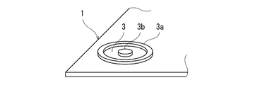
- FIG. 3 is a perspective view showing a groove portion of the mounting table of FIG.
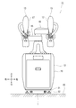
- FIG. 4 is a front view showing an example of the configuration of the robot placed on the table.
- FIG. 5 is a plan view showing the lower surface of the cart of the robot.
- FIG. 6 is a side view showing the universal caster and the fixed caster placed on the table.
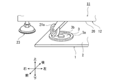
- FIG. 7 is a perspective view showing the universal caster of FIG.
- FIG. 8 is an explanatory view showing a state of the final inspection in the robot assembly line.
- FIG. 9 is a plan view showing a lower surface of a cart of a robot according to another embodiment.
- FIG. 10 is a side view showing a universal caster placed on a table according to another embodiment.
- FIG. 1 is a plan view showing an example of a table 1 according to an embodiment of the present invention.
- 2 is a cross-sectional view taken along the line II-II in FIG.
- FIG. 3 is a perspective view showing a groove portion of the mounting table of FIG.
- the mounting table 1 includes a base plate 2 and an annular groove 3 provided on the base plate 2.
- the base plate 2 is a rectangular flat plate in plan view, and is installed at a predetermined position.
- the grooves 3 are provided at two adjacent corners of the base plate 2.
- Each groove 3 is a recess formed in a substantially annular shape in plan view.
- the concave portion is formed between a convex portion 3a provided in a substantially annular shape in plan view and a convex portion 3b provided in a substantially circular shape in plan view.
- the position of the bottom of the groove 3 and the position of the main surface of the base plate 2 coincide with each other in the thickness direction of the base plate 2 (see FIG. 2).
- the position of the bottom of the groove 3 and the position of the main surface of the base plate 2 are not limited to perfect matching, but allow a slight inclination.
- the base plate 2 is provided at a position corresponding to a fixed caster of the apparatus described later.
- the groove 3 is provided at a position corresponding to a universal caster of the apparatus described later.
- FIG. 4 is a front view showing an example of the configuration of the robot 11.
- the robot 11 includes a carriage 12 and a pair of robot arms (hereinafter sometimes simply referred to as “arms”) 13 and 13 supported by the carriage 12.
- the direction in which the pair of arms is spread is referred to as the left-right direction
- the direction parallel to the axis of the base shaft is referred to as the up-down direction
- the direction orthogonal to the left-right direction and the up-down direction is referred to as the front-back direction.
- Each arm 13 is a horizontal articulated robot arm configured to be movable with respect to the carriage 12 and includes an arm portion 15 and a wrist portion 17.
- the right arm 13 and the left arm 13 may have substantially the same structure.
- An end effector (not shown) is attached to the tip of each arm 13. Further, the right arm 13 and the left arm 13 can operate independently or operate in association with each other.
- the carriage 12 is provided with a main body 20 that houses various units of the robot 11 such as a control device (not shown), and a plurality of casters 21 for moving the robot 11 to a predetermined position. And a plurality of adjusters 22 for restricting and installing the robot 11 at predetermined positions.
- the plurality of casters 21 are placed on the table 1.
- the plurality of adjusters 22 are not placed on the mounting table 1 but are installed on the floor surface 40.
- FIG. 5 is a plan view showing the lower surface of the carriage 12.
- the lower surface of the main body 20 of the carriage 12 has a rectangular shape in plan view.
- casters 21 are installed approximately symmetrically at four locations, front, rear, left, and right, so that substantially the same load is applied to each caster 21.
- the two casters 21 are attached to the left and right sides of the carriage 12, respectively.
- These casters 21 are fixed casters 21b having fixed wheels.
- the fixed caster 21b is placed on the base plate 2 of the table 1.
- the two casters 21 are respectively attached to the left and right sides of the front side of the carriage 12, and these casters 21 are free casters 21a having a free wheel.
- the universal caster 21 a is placed on the groove 3 of the table 1.
- the adjusters 22 are provided at four locations on the outside of the mounting table 1 in plan view and on both the front edge and the rear edge of the lower surface of the main body 20 in order to ensure stability after the robot 11 is installed. Yes.
- FIG. 6 is a side view showing an example of the universal caster 21a and the fixed caster 21b mounted on the mounting table 1.
- the universal caster 21a is accommodated in a groove 3 (concave portion) formed between the convex portion 3a and the convex portion 3b.
- the universal caster 21a is configured to rotate with respect to the main body 20 of the carriage 12 about a vertical axis. This vertical axis passes through the center of the caster mounting portion 20a of the main body portion 20 of the carriage 12 and coincides with the center (3b) of the annular groove 3.
- the fixed caster 21 b is placed on the main surface of the base plate 2.
- the position of the bottom of the groove 3 and the position of the main surface of the base plate 2 coincide with each other in the height direction of the mounting table 1.
- FIG. 7 is a perspective view showing the universal caster 21a of FIG.
- the universal caster 21 a is accommodated in the annular groove 3.
- the universal caster 21a moves along the groove 3 in the groove 3 regardless of the direction of the universal caster 21a.
- the robot 11 is stably placed, and displacement is prevented.
- FIG. 8 is an explanatory view showing a state of the final inspection in the robot assembly line.
- the transfer robot 100 is configured to be able to hold the carriage 12 of the robot 11 by being attached to the robot body 101, the robot arm 102 connected to the robot body 101, and the tip of the robot arm 102.
- the inspection robot 110 includes a camera 110a at the tip.
- the transfer robot 100 places the robot 11 that has completed the assembly process at a predetermined position (on the table 1). After the robot 11 is placed on the table 1 by the transfer robot 100, the holding operation of the robot hand 103 is released. Thereafter, the transfer robot 100 controls the robot arm 102 to move the robot hand 103 away from the robot 11 placed on the table 1 (in the direction of the arrow in FIG. 8). When the robot hand 103 is moved away from the robot 11 and a slight control deviation occurs and the robot hand 103 comes into contact with the robot 11, a greater force is applied to the robot arm 102 than a human being. Misalignment is likely to occur. According to this embodiment, since the universal caster 21a of the carriage 12 moves along the annular groove 3, the robot 11 placed on the table 1 is not displaced.
- the inspection robot 110 takes a picture of the robot 11 placed at a predetermined position by the camera 110a.
- the operator visually inspects the photograph taken by the inspection robot 110. Test results are stored as evidence.
- FIG. 9 is a plan view showing a lower surface of a carriage 12A according to another embodiment.
- the lower surface of the main body 20 of the carriage 12A has a rectangular shape in plan view.
- casters 21 are installed approximately symmetrically at four locations, front, rear, left, and right, so that substantially the same load is applied to each caster 21.
- these four casters 21 are all universal casters 21a having universal wheels.
- the mounting table 1A is provided with four grooves 3 corresponding to the universal casters 21a.
- FIG. 10 is a side view showing the universal caster 21a mounted on the mounting table 1A. As shown in FIG. 10, the universal caster 21a is also housed in the groove 3 (concave portion) formed between the convex portion 3a and the convex portion 3b.
- the device placed on the pedestal 1 is the robot 11, but the device is not limited to this as long as the device has a free caster.
- the universal caster in the groove By placing the universal caster in the groove, the same effect as in the present embodiment can be obtained.
- the present invention is useful for mounting a device having a free caster.
Landscapes
- Engineering & Computer Science (AREA)
- Mechanical Engineering (AREA)
- Robotics (AREA)
- Manipulator (AREA)
Abstract
装置の置台は、自在キャスタを有する装置が載置される置台である。装置の置台は、ベースと、前記ベース上であって、前記自在キャスタに対応する位置に設けられた環状の溝と、を備える。
Description
本発明は、自在キャスタを有する装置の置台に関する。
従来から、重量物等のワークを所定の位置に位置決めするには様々な方法がある。例えば特許文献1には、印刷版を所定の位置に位置決めする印刷版の位置決め装置が開示されている。この方法では、自在キャスタを有する印刷版積載台を装填部の走行用レールに移動挿入し、走行用レールに設けられた凹部と印刷版積載台の固定輪を係合させて、装填部の所定の位置へ印刷版積載台を位置決めするようになっている。
近年では、産業用ロボットの動作を制御してロボットハンドにより重量物等のワークを把持し、所定の位置に運搬することが行われている。
しかし、上記従来の技術では、走行用レールに対して意図しない方向(例えば横方向)に力が加わった場合、固定輪が脱輪しやすい。特に産業用ロボットを制御して、走行用レールの凹部と印刷版積載台の固定輪を係合させることを想定した場合、わずかな制御のずれが生じても、人間と比べて大きな力が働くため、このような問題は顕著である。
本発明は上記のような課題を解決するためになされたもので、自在キャスタを有する装置を安定して載置し、且つ、正確に位置決めを行うことを目的としている。
上記目的を達成するために、本発明のある形態に係る装置の置台は、自在キャスタを有する装置が載置される置台であって、ベースと、前記ベース上であって、前記自在キャスタに対応する位置に設けられた環状の溝と、を備える。
上記構成によれば、自在キャスタが環状の溝の内部に収容されるので、装置に対して意図しない方向に力が加わった場合、装置の自在キャスタがどの方向に向いていても、自在キャスタは環状の溝に沿って移動する。これにより、装置が安定して載置され、位置ずれが防止される。
前記装置は、固定キャスタを更に有し、前記ベースは、前記固定キャスタが載置される平板状の部材を有してもよい。
上記構成によれば、装置の固定キャスタを平板の主面上に載置することができる。装置の安定性が向上する。
前記自在キャスタが載置される前記環状の溝の底部の位置と、前記固定キャスタが載置される前記平板の主面の位置が、前記平板の厚さ方向で一致してもよい。
上記構成によれば、自在キャスタと固定キャスタの高さが一致するので、置台に載置された装置の安定性が向上する。尚、環状の溝の底部の位置と平板の主面の位置が一致するとは、完全一致に限定されず、僅かな傾きを許容するものである。
本発明は、以上に説明した構成を有し、自在キャスタを有する装置を安定して載置し、且つ、正確に位置決めを行うことができる。
以下、好ましい実施形態を、図面を参照しながら説明する。なお、以下では全ての図面を通じて同一または相当する要素には同一の参照符号を付して、その重複する説明を省略する。また、図面は理解しやすくするために、それぞれの構成要素を模式的に示したものである。
図1は、本発明の一実施形態に係る置台1の一例を示す平面図である。図2は、図1のII-II断面図である。図3は、図1の置台の溝部を示した斜視図である。
置台1は、ベースプレート2と、ベースプレート2上に設けられた環状の溝3と、を備える。ベースプレート2は、平面視で矩形状の平板であり、所定の位置に設置される。
溝3は、ベースプレート2の隣り合う二隅に設けられる。各溝3は平面視で略円環状に形成された凹部である。この凹部は、平面視で略円環状に設けられた凸部3aと、平面視で略円状に設けられた凸部3bとの間に形成される。溝3の底部の位置と、ベースプレート2の主面の位置は、ベースプレート2の厚さ方向で一致している(図2参照)。尚、溝3の底部の位置とベースプレート2の主面の位置が一致するとは、完全一致に限定されず、僅かな傾きを許容するものである。
ベースプレート2は後述する装置の固定キャスタに対応する位置に設けられる。溝3は後述する装置の自在キャスタに対応する位置に設けられる。
本実施形態の装置はロボット11である。図4は、ロボット11の構成の一例を示した正面図である。ロボット11は、台車12と、台車12に支持された一対のロボットアーム(以下、単に「アーム」と記載する場合がある)13、13と、を備えている。以下では、一対のアームを広げた方向を左右方向と称し、基軸の軸心に平行な方向を上下方向と称し、左右方向および上下方向に直交する方向を前後方向と称する。
各アーム13は、台車12に対して移動可能に構成された水平多関節型ロボットアームであって、アーム部15とリスト部17とを備えている。なお、右のアーム13および左のアーム13は、実質的に同じ構造であってもよい。各アーム13の先端にはエンドエフェクタ(図示せず)が取り付けられる。また、右のアーム13および左のアーム13は、独立して動作したり、互いに関連して動作したりすることができる。
台車12は、制御装置(図示せず)等のロボット11の各種ユニットを収納する本体部20と、本体部20の下面に設けられ、ロボット11を所定の位置に移動させるための複数のキャスタ21と、所定の位置でロボット11の移動を規制して設置するための複数のアジャスタ22とを有する。複数のキャスタ21は置台1の上に載置される。複数のアジャスタ22は置台1の上には載置されず、床面40に設置される。
図5は、台車12の下面を示した平面図である。図5に示すように、台車12の本体部20の下面は平面視で矩形状を有する。本体部20の下面には、前後左右の四カ所に略対称にキャスタ21が設置され、各キャスタ21に略同じ荷重が加わるようにしている。本実施形態では、二つのキャスタ21は台車12の後方側左右に各々取り付けられており、これらのキャスタ21は固定輪を有する固定キャスタ21bである。固定キャスタ21bは置台1のベースプレート2の上に載置される。また、二つのキャスタ21は台車12の前方側左右に各々取り付けられており、これらのキャスタ21は自在輪を有する自在キャスタ21aである。自在キャスタ21aは置台1の溝3の上に載置される。尚、アジャスタ22はロボット11の設置後の安定性を図るために、平面視で置台1の外側であって、本体部20の下面の前縁及び後縁の両端部の四カ所に設けられている。
図6は、置台1に載置された自在キャスタ21aと固定キャスタ21bの一例を示した側面図である。図6に示すように、自在キャスタ21aは凸部3aと凸部3bとの間に形成された溝3(凹部)の内部に収容される。自在キャスタ21aは鉛直軸を中心に台車12の本体部20に対して回動するように構成されている。この鉛直軸は台車12の本体部20のキャスタ取付部20aの中心を通り、円環状の溝3の中心(3b)と一致している。一方、固定キャスタ21bはベースプレート2の主面上に載置される。
また、溝3の底部の位置と、ベースプレート2の主面の位置は、置台1の高さ方向で一致している。これにより、自在キャスタ21aと固定キャスタ21bの高さが一致するので、置台1に載置された台車12の安定性が向上する。
図7は、図6の自在キャスタ21aを示した斜視図である。図7に示すように、自在キャスタ21aが環状の溝3の内部に収容される。台車12に対して意図しない方向に力が加わった場合、自在キャスタ21aがどの方向に向いていても、自在キャスタ21aは溝3の内部を溝3に沿って移動する。これにより、ロボット11を安定して載置され、位置ずれが防止される。
ロボット11を生産するための組立ラインでは、組立工程が終了した後には、製品の組立最終検査が行われる。図8は、ロボット組立ラインでの最終検査の様子を示した説明図である。図8に示すように、搬送ロボット100は、ロボット本体101と、ロボット本体101に連結されたロボットアーム102と、ロボットアーム102の先端に取り付けられ、ロボット11の台車12を保持可能に構成されたロボットハンド103と、を備える。検査ロボット110は、先端にカメラ110aを備える。
搬送ロボット100は、組立工程が終了したロボット11を所定の位置(置台1の上)に載置する。搬送ロボット100によってロボット11が置台1に載置された後は、ロボットハンド103の保持動作が解除される。その後、搬送ロボット100はロボットアーム102を制御して、ロボットハンド103を置台1に載置されたロボット11から遠ざける(図8の矢印方向)。ロボット11からロボットハンド103を遠ざける際に、わずかな制御のずれが生じて、ロボットハンド103がロボット11に接触した場合、ロボットアーム102には人間と比べて大きな力が働くため、ロボット11の位置ずれが生じやすい。本実施形態によれば、台車12の自在キャスタ21aが環状の溝3に沿って移動するので、置台1の上に載置されたロボット11が位置ずれすることはない。
その後、検査ロボット110は、カメラ110aにより所定の位置に載置されたロボット11を写真撮影する。作業者は、検査ロボット110により撮影された写真を、目視で検査する。検査結果はエビデンスとして保管される。
(その他の実施の形態)
尚、本実施形態では、ロボット11の台車12には自在キャスタ21aと固定キャスタ21bを設けていたが、自在キャスタ21aのみ設けてもよい。図9は、その他の実施形態に係る台車12Aの下面を示した平面図である。図9に示すように、台車12Aの本体部20の下面は平面視で矩形状を有する。本体部20の下面には、前後左右の四カ所に略対称にキャスタ21が設置され、各キャスタ21に略同じ荷重が加わるようにしている。本実施形態では、これら四つのキャスタ21は全て自在輪を有する自在キャスタ21aである。置台1Aには、自在キャスタ21aに対応して四つの溝3が設けられる。図10は、置台1Aに載置された自在キャスタ21aを示した側面図である。図10に示すように、ここでも自在キャスタ21aは凸部3aと凸部3bとの間に形成された溝3(凹部)の内部に収容される。
尚、本実施形態では、ロボット11の台車12には自在キャスタ21aと固定キャスタ21bを設けていたが、自在キャスタ21aのみ設けてもよい。図9は、その他の実施形態に係る台車12Aの下面を示した平面図である。図9に示すように、台車12Aの本体部20の下面は平面視で矩形状を有する。本体部20の下面には、前後左右の四カ所に略対称にキャスタ21が設置され、各キャスタ21に略同じ荷重が加わるようにしている。本実施形態では、これら四つのキャスタ21は全て自在輪を有する自在キャスタ21aである。置台1Aには、自在キャスタ21aに対応して四つの溝3が設けられる。図10は、置台1Aに載置された自在キャスタ21aを示した側面図である。図10に示すように、ここでも自在キャスタ21aは凸部3aと凸部3bとの間に形成された溝3(凹部)の内部に収容される。
尚、本実施形態では、置台1に載置される装置はロボット11であったが、自在キャスタを有する装置であれば、これに限られない。自在キャスタを溝に載置することで、本実施形態と同様の効果を奏することができる。
上記説明から、当業者にとっては、本発明の多くの改良や他の実施形態が明らかである。従って、上記説明は、例示としてのみ解釈されるべきであり、本発明を実行する最良の態様を当業者に教示する目的で提供されたものである。本発明の精神を逸脱することなく、その構造および/または機能の詳細を実質的に変更できる。
本発明は、自在キャスタを有する装置の置台に有用である。
1 置台
11 ロボット(装置)
12 台車
13 アーム
15 アーム部
17 リスト部
21 キャスタ
21a 自在キャスタ
21b 固定キャスタ
22 アジャスタ
100 搬送ロボット
101 本体
102 アーム
103 ハンド
110 検査ロボット
11 ロボット(装置)
12 台車
13 アーム
15 アーム部
17 リスト部
21 キャスタ
21a 自在キャスタ
21b 固定キャスタ
22 アジャスタ
100 搬送ロボット
101 本体
102 アーム
103 ハンド
110 検査ロボット
Claims (4)
- 自在キャスタを有する装置が載置される置台であって、
ベースと、
前記ベース上であって、前記自在キャスタに対応する位置に設けられた環状の溝と、
を備える、装置の置台。 - 前記溝は、平面視で円環状に形成された凹部である、請求項1に記載の装置の置台。
- 前記装置は、固定キャスタを更に有し、
前記ベースは、前記固定キャスタが載置される平板状の部材を有する、請求項1又は2に記載の装置の置台。 - 前記自在キャスタが載置される前記環状の溝の底部の位置と、前記固定キャスタが載置される前記平板の主面の位置が、前記平板の厚さ方向で一致する、請求項3に記載の装置の置台。
Priority Applications (1)
| Application Number | Priority Date | Filing Date | Title |
|---|---|---|---|
| CN201780080317.2A CN110099800A (zh) | 2016-12-26 | 2017-12-20 | 装置的载台 |
Applications Claiming Priority (2)
| Application Number | Priority Date | Filing Date | Title |
|---|---|---|---|
| JP2016-251462 | 2016-12-26 | ||
| JP2016251462A JP7150412B2 (ja) | 2016-12-26 | 2016-12-26 | 装置の置台 |
Publications (1)
| Publication Number | Publication Date |
|---|---|
| WO2018123765A1 true WO2018123765A1 (ja) | 2018-07-05 |
Family
ID=62707658
Family Applications (1)
| Application Number | Title | Priority Date | Filing Date |
|---|---|---|---|
| PCT/JP2017/045736 Ceased WO2018123765A1 (ja) | 2016-12-26 | 2017-12-20 | 装置の置台 |
Country Status (3)
| Country | Link |
|---|---|
| JP (1) | JP7150412B2 (ja) |
| CN (1) | CN110099800A (ja) |
| WO (1) | WO2018123765A1 (ja) |
Citations (4)
| Publication number | Priority date | Publication date | Assignee | Title |
|---|---|---|---|---|
| JPH0425383A (ja) * | 1990-05-21 | 1992-01-29 | Sanyo Electric Co Ltd | 移動作業車 |
| JPH08503438A (ja) * | 1992-12-22 | 1996-04-16 | アール・ディー・インペックス・エイピーエス | 旋回可能なホイールを有するローラキャリッジ |
| JPH09207785A (ja) * | 1996-02-08 | 1997-08-12 | Junzaburo Kawasaki | ストックカート |
| JPH11208481A (ja) * | 1998-01-27 | 1999-08-03 | Rocky Giken:Kk | 上面に円溝を持つキャスター付き台車 |
Family Cites Families (8)
| Publication number | Priority date | Publication date | Assignee | Title |
|---|---|---|---|---|
| GB9715207D0 (en) * | 1996-10-08 | 1997-09-24 | Revvo Castor The Company Limit | Castor assembly |
| JP3168947B2 (ja) * | 1997-07-15 | 2001-05-21 | ゴールドキャスター株式会社 | キャスター |
| JP2000139597A (ja) | 1998-11-16 | 2000-05-23 | Masaaki Fujiwara | キャスター支持体 |
| JP2005349906A (ja) * | 2004-06-09 | 2005-12-22 | Honko Mfg Co Ltd | 運搬用台車 |
| JP3927220B1 (ja) * | 2006-03-31 | 2007-06-06 | 三栄荷役機械株式会社 | 台車 |
| TWM418822U (en) * | 2011-08-01 | 2011-12-21 | Jian-Hong Chen | Structure to fix caster of trolley |
| JP6102706B2 (ja) * | 2013-12-03 | 2017-03-29 | トヨタ車体株式会社 | 台車 |
| JP5848401B2 (ja) * | 2014-06-10 | 2016-01-27 | 株式会社日乃本錠前 | ストッパー付きキャスター |
-
2016
- 2016-12-26 JP JP2016251462A patent/JP7150412B2/ja active Active
-
2017
- 2017-12-20 WO PCT/JP2017/045736 patent/WO2018123765A1/ja not_active Ceased
- 2017-12-20 CN CN201780080317.2A patent/CN110099800A/zh active Pending
Patent Citations (4)
| Publication number | Priority date | Publication date | Assignee | Title |
|---|---|---|---|---|
| JPH0425383A (ja) * | 1990-05-21 | 1992-01-29 | Sanyo Electric Co Ltd | 移動作業車 |
| JPH08503438A (ja) * | 1992-12-22 | 1996-04-16 | アール・ディー・インペックス・エイピーエス | 旋回可能なホイールを有するローラキャリッジ |
| JPH09207785A (ja) * | 1996-02-08 | 1997-08-12 | Junzaburo Kawasaki | ストックカート |
| JPH11208481A (ja) * | 1998-01-27 | 1999-08-03 | Rocky Giken:Kk | 上面に円溝を持つキャスター付き台車 |
Also Published As
| Publication number | Publication date |
|---|---|
| JP7150412B2 (ja) | 2022-10-11 |
| JP2018103302A (ja) | 2018-07-05 |
| CN110099800A (zh) | 2019-08-06 |
Similar Documents
| Publication | Publication Date | Title |
|---|---|---|
| JP5653073B2 (ja) | ロボットセル装置及び生産システム | |
| TWI500491B (zh) | 機械手及機械人 | |
| JP6664830B2 (ja) | 製造システム | |
| KR101952767B1 (ko) | 로봇 | |
| US9540186B2 (en) | Conveyor system and conveyance method | |
| KR20160082412A (ko) | 항공기 동체 자동 장착 및 탈착 장치 | |
| KR20160107811A (ko) | 항공기용 임무장비의 장착 및 분리를 위한 장치 | |
| JPWO2011001675A1 (ja) | ロボットのティーチング装置及びロボットのティーチング方法 | |
| JP2011000669A (ja) | ロボットシステム及び物品並置方法 | |
| JP2017019060A (ja) | 吸着装置、把持装置および搬送方法 | |
| JP2017168841A (ja) | メンテナンス機構 | |
| WO2019092923A1 (ja) | 主型と中子の嵌合装置、及び、主型と中子の嵌合方法 | |
| CN120955031B (zh) | 一种晶圆夹持翻转机构及其控制方法 | |
| JP4831028B2 (ja) | 部品実装用装置の台車位置決め機構及び部品実装用装置用の台車 | |
| US20190344436A1 (en) | Transferring system and method of operating the same | |
| JP2013248695A (ja) | ハンド装置 | |
| JP5610849B2 (ja) | 鉄道車両用連結器の着脱用作業台車 | |
| JP2016007609A (ja) | ワーク操作用ロボットにおけるワーククランプ装置及びその方法 | |
| JP7150412B2 (ja) | 装置の置台 | |
| JP5152498B2 (ja) | ワークの位置決め装置及び方法並びに突合せ溶接用ワークの位置決め装置 | |
| JP2014172094A (ja) | 装着構造、台車、作業装置及び着脱方法 | |
| JP5434888B2 (ja) | 部品供給装置および部品実装装置 | |
| JP4831029B2 (ja) | 部品実装用装置の台車位置決め機構 | |
| JP5760456B2 (ja) | 姿勢調整装置及び昇降装置 | |
| CN222373766U (zh) | 电池模组的操作辅助工装 |
Legal Events
| Date | Code | Title | Description |
|---|---|---|---|
| 121 | Ep: the epo has been informed by wipo that ep was designated in this application |
Ref document number: 17888727 Country of ref document: EP Kind code of ref document: A1 |
|
| NENP | Non-entry into the national phase |
Ref country code: DE |
|
| 122 | Ep: pct application non-entry in european phase |
Ref document number: 17888727 Country of ref document: EP Kind code of ref document: A1 |