WO2018117252A1 - 通信システム、通信管理方法、およびネットワーク管理装置 - Google Patents
通信システム、通信管理方法、およびネットワーク管理装置 Download PDFInfo
- Publication number
- WO2018117252A1 WO2018117252A1 PCT/JP2017/046092 JP2017046092W WO2018117252A1 WO 2018117252 A1 WO2018117252 A1 WO 2018117252A1 JP 2017046092 W JP2017046092 W JP 2017046092W WO 2018117252 A1 WO2018117252 A1 WO 2018117252A1
- Authority
- WO
- WIPO (PCT)
- Prior art keywords
- repeater
- communication
- information
- determination unit
- devices
- Prior art date
Links
Images


Classifications
-
- H—ELECTRICITY
- H04—ELECTRIC COMMUNICATION TECHNIQUE
- H04B—TRANSMISSION
- H04B7/00—Radio transmission systems, i.e. using radiation field
- H04B7/24—Radio transmission systems, i.e. using radiation field for communication between two or more posts
- H04B7/26—Radio transmission systems, i.e. using radiation field for communication between two or more posts at least one of which is mobile
- H04B7/2603—Arrangements for wireless physical layer control
- H04B7/2606—Arrangements for base station coverage control, e.g. by using relays in tunnels
-
- H—ELECTRICITY
- H04—ELECTRIC COMMUNICATION TECHNIQUE
- H04B—TRANSMISSION
- H04B17/00—Monitoring; Testing
- H04B17/30—Monitoring; Testing of propagation channels
- H04B17/309—Measuring or estimating channel quality parameters
-
- H—ELECTRICITY
- H04—ELECTRIC COMMUNICATION TECHNIQUE
- H04B—TRANSMISSION
- H04B17/00—Monitoring; Testing
- H04B17/40—Monitoring; Testing of relay systems
- H04B17/401—Monitoring; Testing of relay systems with selective localization
-
- H—ELECTRICITY
- H04—ELECTRIC COMMUNICATION TECHNIQUE
- H04W—WIRELESS COMMUNICATION NETWORKS
- H04W16/00—Network planning, e.g. coverage or traffic planning tools; Network deployment, e.g. resource partitioning or cells structures
- H04W16/18—Network planning tools
-
- H—ELECTRICITY
- H04—ELECTRIC COMMUNICATION TECHNIQUE
- H04W—WIRELESS COMMUNICATION NETWORKS
- H04W16/00—Network planning, e.g. coverage or traffic planning tools; Network deployment, e.g. resource partitioning or cells structures
- H04W16/24—Cell structures
- H04W16/26—Cell enhancers or enhancement, e.g. for tunnels, building shadow
-
- H—ELECTRICITY
- H04—ELECTRIC COMMUNICATION TECHNIQUE
- H04W—WIRELESS COMMUNICATION NETWORKS
- H04W84/00—Network topologies
- H04W84/18—Self-organising networks, e.g. ad-hoc networks or sensor networks
Definitions
- the present invention relates to a communication system, a communication management method, and a network management apparatus, and is suitable for application to a communication system having a plurality of devices capable of wireless multi-hop communication, for example.
- a technique for determining the placement location of a repeater in a placement candidate for a given repeater, a wireless device that can be connected in one hop is detected, and an excellent repeater placement location is selected from the candidates based on the detection result.
- a technique for determining is disclosed (see Patent Document 1). In this technology, a location that can be connected in one hop to both a radio having a communication path to the gateway and a radio in an isolated state is selected from the placement location candidates, and the actual repeater placement Adopt as a place. By repeating this process until there are no radios in the isolated state, it is possible to determine the arrangement of repeaters that obtain a communication path from all desired radios to the gateway.
- Patent Document 1 that requires information on the placement location candidates of the repeater, it is necessary to select a plurality of placement location candidates in advance. For example, when the repeater is driven by a power source, a method of narrowing the locations where power can be supplied as candidates is conceivable, but when the placement location is flexible, such as when battery-powered, the radio wave propagation characteristics due to shielding in the field It is necessary to consider suitable repeater placement location candidates while taking the above into consideration. In addition, when there is no appropriate arrangement location for the selected candidate, reselection of the arrangement location candidate is required. Furthermore, it is also necessary to install a wireless device for each repeater placement location candidate and to detect a wireless device that can be connected in one hop. Will also take time and effort.
- the present invention has been made in consideration of the above points, and communication that can appropriately calculate the placement position of a repeater in consideration of on-site radio wave propagation characteristics without requiring prior information regarding the placement location candidate of the repeater.
- a system, a communication management method, and a network management apparatus are proposed.
- a communication system having a plurality of devices capable of wireless multi-hop communication, each of the position information of the plurality of devices, a shielding object present at the site where the plurality of devices are provided Based on the site configuration information including the position information and the size information, and the communication quality information between the devices of the plurality of devices, and the repeater for each of the plurality of devices based on the communication quality information
- a determination unit that determines whether or not an addition of a repeater is necessary, position information of a first device that is determined to require addition of a repeater by the determination unit, the first device and the repeater Based on the location information of the second device different from the first device to be communicated via, communication quality information between the first device and the second device, and the field configuration information, Present at the site That calculates the expected values for the attenuation of the received power between the first device and the second device by shield was so provided, a determination unit which determines where to place the repeater.
- a site including a plurality of devices capable of wireless multi-hop communication, position information of each of the plurality of devices, position information and size information of a shield existing at a site where the plurality of devices are provided
- a storage unit that stores configuration information and communication quality information between devices of the plurality of devices, and a communication management method in a communication system that includes the plurality of devices based on the communication quality information
- position information of a second device different from the first device that communicates with the first device via the repeater, and communication quality information between the first device and the second device The site configuration information And an expected value related to the attenuation of received power between the first device and the second device due to a shield present in the field, and determining a position where the repeater is arranged And steps.
- a network management apparatus for managing a network including a plurality of devices capable of wireless multi-hop communication, wherein each of the plurality of devices is provided with location information and the plurality of devices. And a plurality of devices based on the communication quality information, and a storage unit that stores on-site configuration information including position information and size information of the shielding objects present in the device, and communication quality information between the devices of the plurality of devices.
- a determination unit that determines whether it is necessary to add a repeater for each of the first position information, the position information of the first device that is determined to be required to add a repeater by the determination unit, and the first Position information of a second device different from the first device to be communicated with the device via the repeater, communication quality information between the first device and the second device, and the site configuration information Based on And a determination unit that calculates an expected value related to attenuation of received power between the first device and the second device due to a shield present at the site, and determines a position where the repeater is disposed. I did it.
- the location information and communication quality information of the first device determined to require addition of the repeater, and the location information of the second device that communicates with the first device via the repeater.
- positions a repeater is determined based on field configuration information.
- the wireless device and the gateway are connected to information on a partner terminal that can directly communicate with one hop (no repeater).
- the communication quality information with the counterpart terminal is managed respectively.
- the table used for this management is referred to as a neighboring terminal management table.
- the communication system collects information of a neighboring terminal management table from a radio device and a gateway, and manages communication quality information between the radio devices and between the radio device and the gateway by a network configuration management unit.
- this communication system is based on the input from the network construction worker and the like, and the location information of the radio, the location information of the gateway, and the location configuration information such as the location and size of the shielding objects present on the site Managed by the management department.
- the repeater necessity determination unit determines whether or not it is necessary to add a repeater for each radio.
- a radio in an isolated state where there is no counterpart terminal capable of direct communication with one hop (2) A radio with no counterpart terminal capable of direct communication with one hop and having a communication quality equal to or higher than a threshold (3) With one hop There is a partner terminal that can communicate directly and whose communication quality is equal to or higher than the threshold, but the number of corresponding terminals is less than N (N is an arbitrary value of 1 or more)
- this communication system has an appropriate connection destination for each wireless device determined to require addition of a repeater in order to ensure communication connection and improve and stabilize communication quality.
- the connection destination determination unit determines the wireless device or gateway to be used. More specifically, the connection destination determination unit performs the following (A) to (C) for a radio device determined to require addition of a repeater under the above conditions (1) to (3). The connection destination is determined based on the reference.
- B Radio device or gateway (C) 1 with the best communication quality among counterpart terminals capable of direct communication with 1 hop
- the connection destination determination unit when there is a shielding object between the wireless device determined to require the addition of a repeater and another wireless device or gateway, Based on the measured value of the communication quality information managed by the network configuration management unit and the theoretical value calculated from the location information of the radio or gateway, the received power attenuation value by the shielding object is calculated. It is determined whether the radio wave goes straight (transmits) or is detoured.
- the connection destination determination unit determines a wireless device or a gateway as a connection destination based on the expected attenuation value of the received power at this time.
- the communication system includes a repeater that is required to connect each wireless device determined to require a repeater by the repeater necessity determination unit and the connection destination selected by the connection destination determination unit. Is determined by the repeater arrangement determination unit. More specifically, the repeater arrangement determination unit calculates the expected communication range for both the wireless device determined to require the repeater and the connection destination, and recommends overlapping portions of these communication ranges. It is determined as the arrangement location of the repeater. At this time, when there is a shielding object between the wireless device determined to require a repeater and the connection destination, the repeater arrangement determination unit determines whether or not the shielding object is based on the determination in (A) above. Determine the repeater arrangement that allows radio waves to go straight or the repeater arrangement that bypasses. Then, the communication system outputs the determination result as a recommended repeater placement location via a display device or the like.
- the configuration of a communication system, a wireless device, a gateway, and a network management device will be described with reference to FIGS.
- the neighboring terminal management table will be described with reference to FIG.
- processing for engineering support in the wireless multi-hop network related to the layout design of the repeater in the network management apparatus, an operation example thereof, and an accompanying screen display example will be described with reference to FIGS.
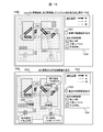
- reference numeral 1 denotes a communication system according to the first embodiment as a whole.
- the communication system 1 includes a plurality of radio devices 200 (200-A to 200-F), a gateway 300, and a network management device 400.
- collected data sensor values such as temperature and pressure
- the gateway 300 transmits (transfers) the data collected from the wireless device 200 to the network management device 400.
- FIG. 1 shows a case where the gateway 300 is connected to the network management apparatus 400 by wire or wirelessly
- the functions of the network management apparatus 400 can be changed to the gateway without separating the gateway 300 and the network management apparatus 400.
- 300 may be integrated into one apparatus.
- some of the functions of the network management device 400 may be realized by another device (the gateway 300 may be another device).
- the radio device 200-F can communicate with the radio device 200-C, but indicates that the communication requirement cannot be achieved. Further, in FIG. 1, the radio device 200-E indicates that there is no radio device capable of communicating in the vicinity and the communication requirement cannot be achieved. For the radio device 200-E and the radio device 200-F, it is necessary to add a repeater at an appropriate place to ensure a stable communication connection. In this regard, in the communication system 1, the location of the repeaters necessary for the radio device 200-E and the radio device 200-F is calculated by the processing procedure shown in FIG. 6 to be described later, and the repeater is added at an appropriate location. Therefore, a stable communication connection can be secured.
- FIG. 2 shows a hardware configuration of the wireless device 200 in the communication system 1.
- the radio device 200 is an embedded device having a communication function with the gateway 300 or another radio device 200.
- the wireless device 200 includes a storage device 201, a central control device 206, a power supply circuit 207, an RF (Radio Frequency) peripheral circuit 208, and an input unit 209.
- the storage device 201 includes a storage device including a read-only semiconductor memory, a storage device including a rewritable semiconductor memory element, and the like, and includes a computer program and management information for realizing various processes (functions). Stores relevant data.
- the storage device 201 stores a communication processing program, a route management program, a neighboring terminal information management program, and a neighboring terminal management table 205.
- Various functions (communication processing unit 202, route management unit 203, neighboring terminal information management unit 204, etc.) in the wireless device 200 are realized by the central control device 206 executing the above-described program stored in the storage device 201.
- the communication processing unit 202 realizes transmission / reception processing in communication. More specifically, packet analysis processing such as packet assembly processing such as transmission destination designation at the time of transmission, determination of whether or not the packet is addressed to the own terminal at the time of reception, and the like are performed.
- the route management unit 203 manages route information in communication within the network.
- the neighboring terminal information management unit 204 manages information related to other wireless devices 200 and gateways 300 existing in the communication range of the wireless device 200, and information related to communication quality with each communication partner (communication target). Update processing of the terminal management table 205, notification processing of neighboring terminal information, and the like are performed.
- the central control unit 206 is a controller such as a CPU (Central Processing Unit) or a microcomputer, and executes various processes.
- the power supply circuit 207 supplies power to the radio device 200, whereby the radio device 200 operates.
- the power supply source is not limited to a specific power source such as an external power source or a battery mounted on the wireless device 200.
- the RF peripheral circuit 208 converts the digital signal and the radio signal to each other, converts the generated digital data into a radio signal, and transmits the radio signal to the other radio device 200, the gateway 300, and the like, and the other radio device 200.
- a receiving unit that extracts digital data from the radio signal received from the gateway 300 or the like.
- the input unit 209 receives input of measurement values and the like from various sensors connected to the wireless device 200.
- the wireless device 200 is not limited to an embedded device, and may be an independent device.
- the input unit is not limited to the interface with the sensor, and may be various sensors.
- the radio device added as a repeater may have the same configuration as that of the radio device 200. However, it is not always necessary to include all the configurations in FIG. 2, and may be a radio device that does not have the input unit 209, for example. In place of the input unit 209, a sensor may be provided.
- FIG. 3 shows a hardware configuration of the gateway 300 in the communication system 1.
- the gateway 300 includes a storage device 301, a central control device 306, a power supply circuit 307, an RF peripheral circuit 308, and an external network connection circuit 309.
- the storage device 301 stores a communication processing program, a route management program, a neighboring terminal information management program, and a neighboring terminal management table 305.
- Various functions (communication processing unit 302, route management unit 303, neighboring terminal information management unit 304, etc.) in the gateway 300 are realized by the central control device 306 executing the above programs stored in the storage device 301. .
- the gateway 300 includes the external network connection circuit 309 and has the same configuration as that of the wireless device 200 except that the input unit 209 is not provided. Therefore, the storage device 301, the central control device 306, the power supply circuit 307, and the RF A detailed description of the peripheral circuit 308 is omitted.
- the gateway 300 communicates with the wireless device 200 using the RF peripheral circuit 308, and communicates with the network management device 400 using the external network connection circuit 309.
- the external network connection circuit 309 is a function for using an external network such as Ethernet (registered trademark), WiFi (registered trademark), an optical line, and a telephone network.
- Ethernet registered trademark
- WiFi registered trademark
- optical line an optical line
- telephone network a telephone network
- the configuration of the network management device 400 will be described with reference to FIG. FIG. 4 shows a hardware configuration of the network management device 400 in the communication system 1.
- the network management device 400 includes a storage device 401, a central control device 410, a power supply circuit 411, an external network connection circuit 412, and a display device 413.
- the storage device 401 includes a communication processing program, a route management program, a collected data management program, a site configuration information management program, a network configuration management program, a repeater necessity determination program, a connection destination determination program, and a repeater arrangement determination program.
- the central control device 410 executes the above-described program stored in the storage device 401, various functions (communication processing unit 402, route management unit 403, collected data management unit 404, site configuration information management in the network management device 400 are performed. Unit 405, network configuration management unit 406, repeater necessity determination unit 407, connection destination determination unit 408, repeater arrangement determination unit 409, and the like. Note that the communication processing unit 402, the path management unit 403, the central control device 410, the power supply circuit 411, and the external network connection circuit 412 have the same configuration as the configuration of the wireless device 200, and thus detailed description thereof is omitted. .
- the collected data management unit 404 manages data such as sensor values collected from the wireless device 200.
- the site configuration information management unit 405 manages (stores) the location information of the radio device 200 and the gateway 300, the location information and size information of the shielding object existing on the site, and the material information of the shielding object when known.
- the network configuration management unit 406 manages (stores) information (neighboring terminal management table information) in the neighboring terminal management table 205 of the wireless device 200 and the neighboring terminal management table 305 of the gateway 300, and between the wireless devices existing in the network. It manages (stores) the link, the link between the wireless device and the gateway, and their communication quality (communication quality information).
- the repeater necessity / unnecessity determination unit 407 determines whether or not a repeater needs to be added for each radio device 200 based on the neighboring terminal management table information managed by the network configuration management unit 406. Based on the determination result, a process of selecting the radio device 200 that needs to add a repeater is performed.
- the connection destination determination unit 408 determines the radio device 200 or the gateway 300 that is an appropriate connection destination for the radio device 200 determined by the repeater necessity determination unit 407 to add a repeater. I do. For example, the connection destination determination unit 408 ensures a predetermined communication quality (communication quality equal to or higher than a threshold) for the radio device 200 selected by the repeater necessity determination unit 407 based on the communication quality information and the field configuration information. The connection destination necessary for the determination is determined, and the connection destination is selected from the wireless device 200 or the gateway 300 based on the determination result.
- a predetermined communication quality communication quality equal to or higher than a threshold
- the repeater arrangement determination unit 409 includes the wireless device 200 determined to require addition of a repeater by the repeater necessity determination unit 407 and the wireless device determined to be an appropriate connection destination by the connection destination determination unit 408.
- the location of the repeater which is necessary for connecting the device 200 or the gateway 300, is determined.
- the repeater arrangement determination unit 409 is based on the communication range of the wireless device 200 selected by the repeater necessity determination unit 407, the communication range of the connection destination selected by the connection destination determination unit 408, and the field configuration information. Then, it is determined whether there is an arrangement location indicating the installation range of the repeater for relaying between the radio device 200 selected by the repeater necessity determination unit 407 and the connection destination selected by the connection destination determination unit 408. And output the determination result.
- the display device 413 is a liquid crystal display device or the like, and the communication quality between the wireless devices 200 existing in the network, the communication quality between the wireless device 200 and the gateway 300, and the repeater placement determined by the repeater placement determination unit 409. Display the output screen showing the location.
- the display device 413 may be configured in the network management device 400 or may be externally connected.
- the function of the network management apparatus 400 may be integrated into the gateway 300 and integrated as one apparatus, or the function of the network management apparatus 400 may be installed in the gateway 300.
- the network management device 400 and the gateway 300 are separated as shown in FIG. 1, both the network management device 400 and the gateway 300 are installed at the site, and the gateway 300 is installed at the site and the network management device 400 is installed. May be installed in another location such as on the cloud.
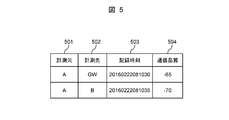
- FIG. 5 shows the configuration of the neighboring terminal management tables 205 and 305 held by the wireless device 200 and the gateway 300 in the communication system 1.
- the neighboring terminal management table shown in FIG. 5 is managed by the neighboring terminal information management unit 204 of the radio device 200 and the neighboring terminal information management unit 304 of the gateway 300.
- Information related to a partner terminal that can communicate directly with each other and communication quality with each communication partner (communication target).
- the measurement source 501 indicates the identifier of the radio device 200 or the gateway 300 that is the communication quality measurement source, that is, the management source of the neighboring terminal management table 205 or the neighboring terminal management table 305. More specifically, it is a field that describes the address, host name, etc. of radio device 200 or gateway 300, and the identifier described in this field preferably conforms to the method adopted in communication system 1. .
- the radio device 200 and the gateway 300 are identified by an IP address, a MAC address, or a unique identifier, these identifiers may be described.
- the identifier of the wireless device 200 is indicated by the subscript portion of FIG. 1, the identifier of the gateway 300 is “GW”, and the contents of the neighboring terminal management table 205 managed by the wireless device 200-A are illustrated.
- the measurement destination 502 indicates an identifier of a partner terminal that can directly communicate with the measurement source 501.
- the radio device 200-A can directly communicate with the gateway 300 and the radio device 200-B.
- the recording time 503 indicates the time when the wireless device 200 or the gateway 300 of the measuring source 501 records the communication quality with the counterpart terminal described in the measuring destination 502.
- the recording time is shown in the format of “year / month / day / hour / minute / second”.
- the recording time is not limited to this format and may be in other formats.
- the communication quality 504 indicates the communication quality between the radio device 200 or the gateway 300 of the measurement source 501 and the counterpart terminal described in the measurement destination 502.
- the received radio wave strength hereinafter referred to as RSSI (Received Signal Strength Indicator)
- RSSI Received Signal Strength Indicator
- the neighboring terminal management tables 205 and 305 of the radio device 200 and the gateway 300 may be provided with a field for recording an arbitrary N times of RSSI according to the capacity of the storage area. .
- RSSI is cited as an index indicating communication quality.
- the index is not limited to this index, and other configurations such as packet loss rate and other information are managed as an index of communication quality.
- a plurality of communication quality indicators may be managed by the neighboring terminal management tables 205 and 305.
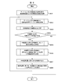
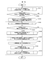
- FIG. 6 shows a processing procedure related to the main processing relating to the layout design of the repeaters in the communication system 1.
- the network management device 400 relays each wireless device 200 based on the information in the neighboring terminal management tables 205 and 305 collected from each wireless device 200 and the gateway 300 according to the processing of FIG.
- the wireless device 200 or the gateway 300 that is an appropriate connection destination is determined with respect to the wireless device 200 that has determined that a repeater is necessary.
- the network management device 400 determines the location of the repeater necessary for connecting the wireless device 200 determined to require the repeater and the connection destination, and the recommended location of the repeater. As a result, the determination result is displayed via the display device 413.
- on-site configuration information such as position information of the gateway 300 and the wireless device 200
- shielding object information such as position information and size information of the shielding object
- the network management device 400 acquires the site configuration information (step S601).
- the input screen 700 may be configured to be displayed on the display device 413 or may be configured to be displayed on another device.
- the network management device 400 includes an input device (not shown) such as a mouse, a keyboard, and a touch panel, and an input operation is performed via the input device.
- an input method by an operator who performs engineering of a wireless multi-hop network an example in which field configuration information is input via the display device 413 of the network management device 400 will be described later with reference to FIG. To do.
- the input of the site configuration information is not limited to a specific method. For example, when the radio device 200, the gateway 300, etc.
- step S601 the network management apparatus 400 moves the process to step S602.
- step S602 the network management device 400 collects information on the neighboring terminal management tables 205 and 305 from the gateway 300 and the wireless device 200. Details of the collection processing in step S602 will be described later with reference to FIG. By collecting information in the neighboring terminal management tables 205 and 305 held by the gateway 300 and the wireless device 200, the network management apparatus 400 can communicate the communication quality of each terminal with which the gateway 300 and the wireless device 200 can communicate with each other. It can be managed as configuration information. When the network management apparatus 400 finishes the process of step S602, the network management apparatus 400 moves the process to step S603.
- step S603 the network management device 400 determines whether or not the relay device of each wireless device 200 needs to be added based on the communication quality information between the wireless devices 200 and between the wireless device 200 and the gateway 300.
- step S603 the wireless device 200 that needs to secure communication connection by adding a repeater, stabilize the communication quality, such as the wireless device 200 that cannot achieve the communication requirements with the network configuration at that time, is extracted. Details of the repeater necessity determination process in step S603 will be described later with reference to FIG.
- the network management apparatus 400 finishes the process of step S603, the network management apparatus 400 moves the process to step S604.
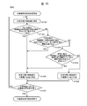
- step S604 the network management apparatus 400 determines whether or not there is a wireless device 200 that is determined to require addition of a repeater based on the determination result in step S603. If the network management device 400 determines that there is a wireless device 200 that has been determined to require addition of a repeater (in the case of YES), the network management apparatus 400 moves the process to step S605 and determines that it does not exist (in the case of NO). Since all the radio devices 200 are in a state where the predetermined communication requirements can be achieved and no additional repeater is required, the main process is terminated.
- step S605 the network management device 400 determines the radio device 200 or gateway 300 that is an appropriate connection destination for each radio device 200 determined to require a repeater in step S603. Details of the connection destination determination processing in step S605 will be described later with reference to FIG. When the network management apparatus 400 finishes the process of step S605, the network management apparatus 400 moves the process to step S606.
- step S606 the network management apparatus 400 determines the location of the repeater required to connect the wireless device 200 determined to require a repeater in step S603 and the connection destination determined in step S605. To do. By performing the repeater placement determination process in step S606, it is possible to calculate a recommended repeater placement location even in an environment that does not have a repeater placement location candidate in advance. Details of the repeater arrangement determination processing in step S606 will be described later with reference to FIG. When the network management apparatus 400 finishes the process in step S606, the network management apparatus 400 moves the process to step S607.
- step S607 the network management device 400 displays the determination result obtained in step S606 on the display device 413.
- An operator who performs engineering of the wireless multi-hop network can easily determine where to additionally install the wireless device 200 as a repeater by referring to the output result.
- the network management apparatus 400 moves the process to step S608.
- step S608 the network management apparatus 400 has performed an operation in which the operator has installed the radio device 200 that will be a repeater on the actual site, based on the determination result of the repeater arrangement displayed in step S607. Is detected (an input indicating that the work has been completed is accepted).
- the operator installs a radio device to be a repeater at a location that can be installed closest to the displayed arrangement location of the repeater. To do.
- the network management apparatus 400 grasps the completion of the installation, the network management apparatus 400 moves the process to step S602 again and collects the neighboring terminal management table information.
- the network management apparatus 400 repeatedly performs the process of FIG. 6 until there is no radio device 200 determined to require addition of a repeater (until NO is determined in step S604).
- the arrangement of repeaters necessary for all the radio devices 200 to achieve predetermined communication requirements is calculated.
- FIG. 7A a screen display example (input screen) for inputting the field configuration information displayed on the display device 413 of the network management device 400 according to a user operation 700) will be described.
- the input screen 700 is provided with a display area 701 for displaying a site layout (map information), the radio device 200, and the like.
- the input screen 700 is provided with an item 702 for switching input contents related to site configuration information.
- a site layout such as a map is displayed, and then the location information of the radio device 200 and the gateway 300 is input by a mouse operation or the like by an operator, thereby managing the location information. It becomes possible to do.
- scale information on the screen for example, even when specific latitude information and longitude information such as the radio device 200 and the gateway 300 cannot be grasped, based on the distance and scale information on the screen, It is possible to manage the distance between the wireless devices 200 and the distance between the wireless devices 200 and the gateway 300. Further, as described above, when GPS information or the like is held, such information may be automatically input on the screen.
- a drawing cursor 703 for inputting the shielding object information is displayed.
- the operator can draw the shielding object 704 existing on the site on the screen and input the position information and size information of the shielding object.
- material information such as metal and concrete may be input as in the material information input unit 705.
- the input of material information is not essential. Note that, as described above, when the on-site structural information is known and the precise position information and size information of the shielding object can be grasped, this information is automatically input without depending on the input by the operator. Also good.
- the position information of the radio device 200 and the gateway 300 and the shielding object information input as described above are stored in the storage device 401.
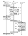
- FIG. 8 shows an example of a sequence diagram relating to the collection processing of the neighboring terminal management table information in the communication system 1.
- the network management device 400 collects the neighboring terminal management table information held by the gateway 300 and the radio device 200 as network configuration information, there is a method of performing the process of FIG. 8, for example.
- step S801 the network management device 400 transmits a neighboring terminal information request packet to the gateway 300.
- the neighboring terminal information request packet is a packet that requests a designated terminal to notify neighboring terminal management table information held by the terminal.
- step S802 the gateway 300 receives a neighboring terminal information request packet.
- the communication processing unit 302 of the gateway 300 refers to the final destination of the packet and confirms that it is requested to notify the neighboring terminal management table information. Also, the communication processing unit 302 notifies the neighboring terminal information management unit 304 that the neighboring terminal management table information is requested.
- the neighboring terminal information management unit 304 of the gateway 300 receives a notification that the neighboring terminal management table information is requested, and transmits a response request packet by broadcast.
- the response request packet is a packet that requests a neighboring terminal that has received the response request packet to return a response packet.
- the gateway 300 receives the response packet from the receiving terminal of the response request packet, that is, the partner terminal capable of direct communication with one hop, analyzes the packet with the communication processing unit 302, and sends it to the neighboring terminal information management unit 304. Notify that a response has been received. Thereafter, when the neighboring terminal information management unit 304 confirms the reception of the response packet, the neighboring terminal information management unit 304 updates the neighboring terminal management table 305, the response packet transmission source at the measurement destination 502, the response packet reception time at the recording time 503, and the communication quality 504. The communication quality information such as RSSI at the time of receiving the response packet is recorded. Note that the processing related to transmission / reception of response request packets and response packets may be performed a plurality of times. This number of times may be set arbitrarily, and increasing the number of times makes it possible to detect neighboring terminals with high accuracy.
- step S805 the gateway 300 transmits a neighboring terminal information response packet storing the updated neighboring terminal management table information to the network management apparatus 400.
- step S806 the network management device 400 receives the neighboring terminal information response packet from the gateway 300.
- the network configuration management unit 406 records the neighboring terminal management table information of the gateway 300 in the storage device 401 as network configuration information.
- step S807 the network management device 400 transmits a neighboring terminal information request packet to the wireless device 200 under the gateway 300.
- the radio device 200 and the gateway 300 hold the communication route information in the route management units 203 and 303 by autonomous communication route control or the like, it is only necessary to specify the final destination in the neighboring terminal information request packet.
- the wireless device 200 and the gateway 300 do not hold the communication route information, such as when the route management unit 403 of the network management device 400 performs centralized control of the communication route, the relay route information is also stored in the neighboring terminal information request packet, Transmission is performed by source routing based on the stored relay route information.
- step S808 the gateway 300 receives the neighboring terminal information request packet.
- the communication processing unit 302 of the gateway 300 refers to the final destination of the packet and transfers the packet to an appropriate transfer destination.
- the gateway 300 performs transfer according to the information.
- the gateway 300 performs the transfer according to the information specified by the source routing.
- step S809 the radio device 200 specified in the network management apparatus 400 in step S807 receives the neighboring terminal information request packet, refers to the final destination of the packet in the communication processing unit 202 of the radio device 200, and sets the neighboring terminal to itself. Confirm that notification of management table information is requested. At this time, the communication processing unit 202 of the wireless device 200 notifies the neighboring terminal information management unit 204 that neighboring terminal management table information is requested.
- step S810 the neighboring terminal information management unit 204 receives notification that the neighboring terminal management table information is requested, and transmits a response request packet by broadcast.
- step S811 the wireless device 200 receives a response packet from the response request packet receiving terminal, analyzes the response packet by the communication processing unit 202, and notifies the neighboring terminal information management unit 204 that the response has been received. After that, when the neighboring terminal information management unit 204 confirms reception of the response packet, the neighboring terminal information management unit 204 updates the neighboring terminal management table 205 as in step S804.
- step S812 the wireless device 200 transmits a neighboring terminal information response packet storing the updated neighboring terminal management table information to the network management apparatus 400.
- the neighboring terminal information request packet is transmitted by source routing in step S807
- the reverse of the order of the relay routes stored in the response packet is stored as the relay route information in the neighboring terminal information response packet.
- the neighbor terminal information response packet can be transmitted to the network management apparatus 400 by source routing.
- step S813 the gateway 300 receives the neighboring terminal information response packet, refers to the final destination of the packet in the communication processing unit 302 of the gateway 300, and transfers the neighboring terminal information response packet to the network management device 400.
- step S814 the network management device 400 receives a neighboring terminal information response packet from the wireless device 200.
- the network configuration management unit 406 records the neighboring terminal management table information of the wireless device 200 in the storage device 401 as network configuration information.
- the neighboring terminal management table information is collected from each wireless device 200, and the network configuration By recording by the management unit 406, it is possible to manage the entire configuration of the network.
- the network management apparatus 400 transmits the neighbor terminal information request packet, if no response is obtained even after a predetermined time has passed, retransmission processing may be performed as appropriate. It can be inferred that the wireless device 200 that has not received a response even after a certain number of retransmission processes is in an isolated state that has not yet entered the network.
- the network management apparatus 400 appropriately instructs the gateway 300 and the wireless device 200 to collect the neighboring terminal management table information.
- the gateway 300 and the wireless device 200 collect the neighboring terminal management table information.
- the configuration may be such that the neighboring terminal management table information is autonomously transmitted to the destination at a constant cycle.
- a wireless device compliant with the wireless standard WirelessHART registered trademark
- the terminal management table information collection process may be realized.
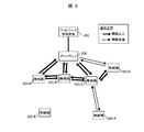
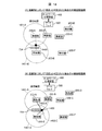
- FIG. 9 shows a network configuration example based on the collection result of the neighboring terminal management table information in the communication system 1.
- the network management apparatus 400 collects information (neighboring terminal management table information) of the neighboring terminal management table 205 illustrated in FIG. 5 from the transceiver 200-A of FIG. 1 in step S602 of FIG. It can be understood that the 200-A can directly communicate with the gateway 300 and the radio device 200-B in one hop and can communicate with the communication quality of -65 dBm and -70 dBm, respectively.
- the network configuration management unit 406 in the network management device 400 the communication between all the wireless devices 200 as shown in FIG.
- the connectivity between the wireless devices 200 can be grasped as configuration information of the wireless network.
- the determination is performed based on the configuration information as shown in FIG.
- the communication quality of the link is illustrated with a solid line (above the threshold) and a dotted line (below the threshold) depending on whether the communication quality is over the threshold.
- This communication quality threshold is set as a level indicating whether or not the communication requirement required for the communication system 1 can be achieved.
- the threshold value is retained as a variable parameter, and the operator can display the communication quality information described later, a screen for displaying the determination result of the arrangement location of the repeater, etc. It may be configured to be dynamically defined as appropriate.
- FIG. 10 shows a processing procedure related to the repeater necessity determination process in the communication system 1.
- the repeater necessity determination unit 407 can determine whether or not it is necessary to add a repeater to each radio device 200 based on the information managed by the network configuration management unit 406 by performing the processing of FIG. It becomes possible.
- step S ⁇ b> 1001 the repeater necessity determination unit 407 selects one wireless device 200 to be determined as a necessity for the repeater from all the wireless devices 200.
- the repeater necessity determination unit 407 ends the process of step S1001, the process proceeds to step S1002.
- step S1002 the repeater necessity determination unit 407 determines whether or not the determination target wireless device 200 is in an isolated state where there is no other party that can directly communicate with one hop in the vicinity.
- the radio device 200-E corresponds to the isolated state.
- the repeater necessity determination unit 407 moves to step S1005 and determines that the determination is not in an isolated state (in the case of NO). The process moves to step S1003.
- the repeater necessity determination unit 407 determines the communication quality with the other party for the radio device 200 to be determined, which can be directly communicated with one hop. Whether the communication quality is less than the threshold value. For example, in the example of FIG. 9, the radio device 200-F can only communicate directly with the radio device 200-C, but the communication quality is less than the threshold value, and therefore the predetermined communication requirement cannot be satisfied. Matches the judgment conditions.
- the repeater necessity determination unit 407 moves the process to step S1005, and the communication partner whose threshold is equal to or higher than the threshold. Is determined to be present (NO), the process proceeds to step S1004.
- the repeater necessity determination unit 407 determines whether there are N or more wireless devices 200 that can directly communicate with one hop and whose communication quality is equal to or higher than a threshold for the wireless device 200 to be determined. Determine whether.
- N is set to a value of 2 or more, the presence / absence of redundancy is also included in the necessity determination of the repeater. It becomes. As the value of N is increased, a communication system with higher redundancy and fault tolerance can be constructed. However, since the number of necessary repeaters increases, the cost also increases. N is an arbitrary value of 1 or more, and it is preferable to set N appropriately considering these trade-offs.
- the only communication partner that can communicate directly and whose communication quality is equal to or higher than the threshold is the radio device 200-C, and the communication connection with the radio device 200-C is interrupted. It is not possible to secure a route that provides communication quality equal to or higher than the threshold.
- radio apparatus 200-D there is only one communication partner with which communication quality is equal to or higher than the threshold and can be directly communicated.
- the repeater necessity determination unit 407 determines that there are N or more communication partners whose communication quality is equal to or higher than the threshold for the determination target wireless device 200 (in the case of YES), the repeater necessity determination unit 407 moves the process to step S1005, If it is determined that it exists beyond (NO), the process proceeds to step S1006.
- step S1005 the repeater necessity determination unit 407 determines that the wireless device 200 that meets any of the determination conditions in steps S1002 to S1004 is a wireless device 200 that requires the addition of a repeater. That is, (1) an isolated radio device 200 in which there is no counterpart terminal capable of direct communication with one hop, and (2) a radio device 200 in which there is no counterpart terminal capable of direct communication with one hop and whose communication quality is equal to or greater than a threshold value (3) Although there is a partner terminal capable of direct communication in one hop and having a communication quality equal to or higher than a threshold, the wireless device 200 having the number of corresponding terminals less than N is determined as a wireless device 200 that needs to add a repeater. To do.
- the repeater necessity determination unit 407 ends the process of step S1005, the process proceeds to step S1007.
- step S1006 the repeater necessity determination unit 407 determines that the wireless device 200 that does not meet any of the determination conditions in steps S1002 to S1004 is a wireless device 200 that does not require addition of a repeater. With respect to the wireless device 200, it is possible to determine that a repeater is unnecessary because predetermined communication requirements can be achieved without adding a repeater.
- the repeater necessity determination unit 407 ends the process of step S1006, the process proceeds to step S1007.
- step S1007 the repeater necessity determination unit 407 determines whether or not the repeater necessity determination for all the radio devices 200 has been completed. When it is determined that the necessity determination of the repeaters of all the radio devices 200 has been completed (in the case of YES), the repeater necessity determination process is terminated, and when it is determined that there are still undecided radio devices 200 (NO) ), The process proceeds to step S1001, and the undetermined wireless device 200 is selected as a determination target, and the necessity determination of the repeater is repeated.
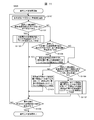
- connection destination determination process executed by the connection destination determination unit 408 of the network management apparatus 400 in step S605 of FIG. 6 will be described with reference to FIG.
- FIG. 11 shows a processing procedure related to a connection destination determination process in the communication system 1.
- the connection destination determination unit 408 performs a network configuration management unit for the wireless device 200 that is determined to require addition of a repeater in the repeater necessity determination process of FIG. 10 by performing the process of FIG. Based on the management information 406 and the like, it is possible to determine (determine) which radio device 200 or gateway 300 should be connected.
- step S1101 the connection destination determination unit 408 determines the wireless device that is the target of the connection destination determination process from among the wireless devices 200 that are determined to require addition of the relay device in the repeater necessity determination process of FIG. One 200 is selected.
- the connection destination determination unit 408 finishes the process of step S1101, the connection destination determination unit 408 moves the process to step S1102.
- step S1102 the connection destination determination unit 408 determines whether the determination target wireless device 200 is in an isolated state where there is no other party that can directly communicate with one hop. If the connection destination determination unit 408 determines that the determination target wireless device 200 is in an isolated state (in the case of YES), the connection destination determination unit 408 moves the process to step S1103, and determines that it is not in an isolated state (in the case of NO). The process moves to S1104.
- the connection destination determination unit 408 determines the radio device 200 or the gateway 300 having the smallest expected value for attenuation of received power as an appropriate connection destination for the radio device 200 in the isolated state.
- the communication success rate improves as the expected value of the attenuation amount is smaller with respect to the transmitted radio wave and the received power is larger. For this reason, here, a partner terminal having a small expected value of received power attenuation is determined as a connection destination. Details of the determination process will be described later with reference to FIG.
- the connection destination determination unit 408 ends the process of step S1103, the connection destination determination unit 408 moves the process to step S1109.
- step S ⁇ b> 1104 the connection destination determination unit 408 determines whether there is a partner that can directly communicate with one hop for the determination target wireless device 200, but the communication quality with the partner is all less than the threshold value. . If the connection destination determination unit 408 determines that there is only a communication partner whose communication quality is less than the threshold for the determination target wireless device 200 (YES), the process proceeds to step S1105, and there is a communication partner that is equal to or greater than the threshold. If so (NO), the process moves to step S1106.
- step S1105 the connection destination determination unit 408 appropriately selects the radio device 200 or gateway 300 having the best communication quality among the counterpart devices capable of direct communication with respect to the radio device 200 in which there is no counterpart terminal having a communication quality equal to or higher than the threshold value. It is determined as a connection destination. This is because there is a possibility that the communication quality is improved and stabilized by adding a repeater, even if the communication partner whose communication quality is less than the threshold value has a communication connection regardless of the presence or absence of an obstacle. This is because it is expensive. For example, in the example of FIG. 9, since the wireless device 200-F has a communication connection with the wireless device 200-C, although the communication quality is less than the threshold, the wireless device 200-C is the appropriate connection destination. Selected. When the connection destination determination unit 408 finishes the process of step S1105, the connection destination determination unit 408 moves the process to step S1109.
- step S ⁇ b> 1106 the connection destination determination unit 408 determines whether the determination target wireless device 200 is in an isolated state when a partner terminal capable of direct communication and whose communication quality is equal to or higher than a threshold is excluded from the determination target wireless device 200. Determine whether or not.
- the connection destination determination unit 408 determines that the wireless device 200 to be determined is in an isolated state due to the above exclusion (in the case of YES)
- step S1106 the determination is performed in step S1106.
- the wireless device 200-C whose communication quality is equal to or higher than the threshold value is excluded from the wireless device 200-D, the gateway 300 whose communication quality is lower than the threshold value remains as a communication partner, and thus step S1106 for the wireless device 200-D is performed. In this determination, it is determined that the isolated state is not reached.
- step S ⁇ b> 1107 the connection destination determination unit 408 excludes the partner terminal that can directly communicate with the determination target wireless device 200 and whose communication quality is equal to or higher than the threshold, and then has the smallest expected value of attenuation related to received power.
- the device 200 or the gateway 300 is determined as an appropriate connection destination. This is because, in order to ensure the redundancy of the communication connection, the radio device 200 or the gateway 300 that can obtain the highest received power and is expected to have a good communication success rate is selected as the connection destination. Details of the determination processing will be described later with reference to FIG.
- the connection destination determination unit 408 finishes the process of step S1107, the connection destination determination unit 408 moves the process to step S1109.
- the connection destination determination unit 408 excludes the partner terminal capable of direct communication and whose communication quality is equal to or higher than the threshold for the wireless device 200 to be determined, and then determines the communication quality from among the partner terminals capable of direct communication. Determines the best radio 200 or gateway 300 as an appropriate connection destination. This is because, in order to ensure the redundancy of the communication connection, the radio device 200 or the gateway 300 that is most likely to be stabilized by improving the communication quality by adding a repeater is selected as the connection destination, as described above. It is. In the example of FIG. 9, according to the determination process, the gateway 300 is selected as the connection destination of the radio device 200-D.
- the connection destination determination unit 408 ends the process of step S1108, the connection destination determination unit 408 moves the process to step S1109.
- step S1109 the connection destination determination unit 408 determines whether or not the connection destination determination has been completed for all the wireless devices 200 that have been determined to require addition of repeaters.
- the connection destination determination unit 408 determines that the determinations for all the radio devices 200 have been completed (in the case of YES)
- the connection destination determination unit 408 ends the connection destination determination process and determines that there are still undecided radio devices 200 (NO). )
- the process proceeds to step S1101, the wireless device 200 that has not been determined is selected as a determination target, and the connection destination determination is repeated.
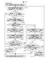
- FIG. 12 shows a processing procedure related to the minimum attenuation expected value connection destination selection processing in step S1103 and step S1107 in FIG.
- the connection destination determination unit 408 can select the connection destination having the smallest expected attenuation value of the received power in consideration of the influence of the shielding object existing in the field by performing the processing of FIG. .
- step S1201 the connection destination determination unit 408 selects the radio device 200 or the gateway 300 having the shortest distance as a connection destination candidate when viewed from the radio device 200 selected in step S1101 of FIG. This is because the radio wave tends to attenuate with distance, and when there is no shielding object, the expected attenuation value becomes small in the radio device 200 or the gateway 300 existing at the shortest distance.
- the connection destination determination unit 408 ends the process of step S1201
- the connection destination determination unit 408 moves the process to step S1202.
- step S1202 the connection destination determination unit 408 selects the radio device 200 selected in step S1101 in FIG. 11 based on the on-site configuration information managed by the on-site configuration information management unit 405 of the network management device 400, and the selection in step S1201. It is determined whether or not there is a shield between the wireless device 200 and the gateway 300.
- the connection destination determination unit 408 moves the process to step S1204 when it is determined that a shielding object is present (in the case of YES), and moves to step S1203 when it is determined that there is no obstacle (in the case of NO). For example, in the example of FIG.
- step S1101 when the wireless device 200 selected in step S1101 is “E” (wireless device 200-E), “A” (wireless device 200-E) is present at the shortest distance. A), and since the shielding object 704 exists on the transmission line (the straight line between “A” and “E”), the process proceeds to step S1204.
- the connection destination determination unit 408 selects the wireless device 200 or gateway 300 selected in step S1201 as the connection destination of the wireless device 200 selected in step S1101 of FIG. This is because, as described above, when there is no shield on the transmission path, the expected attenuation value is minimized in the radio device 200 or the gateway 300 at the shortest distance.
- the connection destination determination unit 408 ends the minimum attenuation expected value connection destination selection process when the process of step S1203 ends.
- the connection destination determination unit 408 determines the received power attenuation amount due to the shielding object existing between the radio device 200 selected in step S1101 in FIG. 11 and the radio device 200 or gateway 300 selected in step S1201. calculate. More specifically, the connection destination determination unit 408 first calculates a theoretical value of received power from the distance between two terminals. For example, by applying the Friis transmission formula, it is possible to calculate a theoretical value of the attenuation with respect to the distance when there is no shield, and for the transmission output of the radio device 200 or the gateway 300, By applying a theoretical value, a theoretical value of received power can be derived.
- the connection destination determination unit 408 obtains the difference between the measured value of the received power based on the information in the neighboring terminal management tables 205 and 305 collected from each radio device 200 and the gateway 300 and the above theoretical value, thereby blocking the shielding object. Calculate the attenuation due to. For example, it is assumed that the theoretical value of received power is “ ⁇ 70 dBm”. At this time, it is assumed that the measured value on the neighboring terminal management table is that the received power is not measured, that is, is lower than the minimum reception sensitivity of the radio device 200 or the gateway 300. For example, when the minimum receiving sensitivity is “ ⁇ 90 dBm”, it can be said that at least 20 dBm of attenuation is generated by the shielding object.
- the connection destination determination unit 408 calculates the attenuation amount of the reception power due to the shielding object from the theoretical value and the actual measurement value of the reception power.
- the attenuation amount by the shielding object may be estimated based on the material information.
- step S1205 the connection destination determination unit 408 determines whether or not the attenuation amount due to the shielding object is less than a threshold value.
- the threshold value can be set to any appropriate value. If the connection destination determination unit 408 determines that the amount of attenuation by the shielding object is less than the threshold (in the case of YES), the connection destination determination unit 408 moves the process to step S1206, and determines that the attenuation is greater than or equal to the threshold (in the case of NO), step S1209. Move processing to.
- step S1206 the connection destination determination unit 408 selects the wireless device 200 or gateway 300 selected in step S1201 as the connection destination of the wireless device 200 selected in step S1101 of FIG. Then, it is decided to take a form that allows the object to go straight (permeate radio waves) with respect to the shield. This is because, in the determination of step S1205, when the attenuation amount by the shielding object is less than the threshold value, it is expected that a constant reception power can be maintained even if communication is performed by transmitting radio waves to the shielding object. .
- the connection destination determination unit 408 ends the process of step S1206, the connection destination determination unit 408 moves the process to step S1207.
- step S1207 the connection destination determination unit 408 tentatively selects the location where the repeater is arranged in step S1101 in FIG. It is set on a straight line with the radio device 200 or the gateway 300. An example of this setting will be described later with reference to FIG.
- the connection destination determination unit 408 moves the process to step S1208.
- the connection destination determination unit 408 determines the theoretical value of communication quality between the repeater and the wireless device 200 selected in step S1101 in FIG. In addition, it is determined that the theoretical value of the communication quality between the repeater and the radio device 200 or the gateway 300 selected in step S1201 is equal to or greater than the threshold value. More specifically, the connection destination determination unit 408 calculates the theoretical value of the attenuation when there is no shielding object, for example, by applying the Friis transmission formula to the distance from the repeater, and further repeaters If there is a shielding object between the two, the amount of attenuation by the shielding object calculated in step S1204 is added to the attenuation value.
- connection destination determination unit 408 can derive the theoretical value of the received power by applying the attenuation amount to the transmission output of the radio device 200 or the gateway 300.
- the connection destination determination unit 408 determines that all of the theoretical received power is equal to or higher than a threshold value (communication quality such as a communication success rate derived from the received power may be equal to or higher than the threshold value). ),
- the minimum attenuation expected value connection destination selection process is terminated because it is expected that the predetermined communication quality is satisfied even if the radio wave travels straight with respect to the shielding object.
- the connection destination determination unit 408 does not satisfy the predetermined communication quality. It is determined that detouring is appropriate, and the process proceeds to step S1209.
- step S1209 the connection destination determination unit 408 selects the radio device 200 or gateway 300 selected in step S1201 as the connection destination of the radio device 200 selected in step S1101 in FIG. Decide to take the form of diverting radio waves to things. This is because when the attenuation amount by the shielding object is equal to or greater than the threshold value, it is expected that the attenuation amount is very large even if the radio wave travels straight with respect to the shielding object, and a constant received power cannot be maintained.
- the connection destination determination unit 408 ends the process of step S1209, the connection destination determination unit 408 moves the process to step S1210.
- step S1210 the connection destination determination unit 408 temporarily sets the location of the repeater from the radio 200 selected in step S1101 in FIG.
- the tangent drawn with respect to the tangent drawn with respect to the shielding object from the radio device 200 or the gateway 300 selected in step S1201 is set. An example of this setting will be described later with reference to FIG.
- the connection destination determination unit 408 moves the process to step S1211.
- the connection destination determination unit 408 determines the wireless device selected in step S1201 via the relay device from the wireless device 200 selected in step S1101 in FIG. 11 in the arrangement of the relay devices provisionally set in step S1210. It is determined whether the distance to 200 or the gateway 300 is shorter than the distance to the other radio device 200 or the gateway 300. Such a determination is made when the propagation distance of radio waves increases due to detours, and when the propagation distance becomes shorter when the other radio device 200 or the gateway 300 is connected to, the latter is used to attenuate the received power. This is because the expected value is expected to be small.
- connection destination determination unit 408 determines that the distance to the wireless device 200 or the gateway 300 selected in step S1201 is the smallest even if the repeater arrangement for bypassing the radio wave with respect to the shield is set ( In the case of YES), the minimum attenuation expected value connection destination selection process is terminated, and on the other hand, when it is determined that the distance from the other radio device 200 or gateway 300 is shorter (in the case of NO), the process proceeds to step S1212. .
- connection destination determination unit 408 excludes the wireless device 200 or the gateway 300 selected in step S1201 from the connection destination.
- the connection destination determination unit 408 excludes the wireless device 200 or the gateway 300 as a connection destination in both cases of straight travel and detour due to the influence of the shielding object. Move the process and repeat the determination of the connection destination.
- the radio wave propagation characteristics in the field are selected in selecting the connection destination of the wireless device 200 determined to require addition of the repeater in the repeater necessity determination processing of FIG. Selection that takes into account is possible.
- FIG. 13 shows a processing procedure related to repeater arrangement determination processing in the communication system 1.
- the repeater arrangement determination unit 409 performs the processing of FIG. 13 to determine the connection destination determination of the wireless device 200 determined in FIG. 10 that it is necessary to add a repeater in the repeater necessity determination processing of FIG. It is possible to determine the location of the repeater, which is necessary for connecting the connection destination selected in the processing.
- step S1301 the repeater arrangement determination unit 409 is selected by the wireless device 200 determined to require addition of a repeater in the repeater necessity determination process of FIG. 10 and the connection destination determination process of FIG. One pair to be determined is selected from the pair with the connection destination.
- the repeater arrangement determination unit 409 moves the process to step S1302 when the process of step S1301 is completed.
- the repeater arrangement determination unit 409 is expected for each of both the radio device 200 determined to require addition of a repeater and the selected connection destination in the determination target pair.
- Examples of the communication range used in the processing include a method of applying a communication range that theoretically obtains communication quality equal to or higher than a threshold value based on a theoretical expression related to radio wave propagation such as a Friis transmission formula.
- the communication range is the longest distance among the wireless devices 200 or the distances between the wireless devices 200 and the wireless devices 200 in which communication quality equal to or higher than the threshold is secured. The method of applying is also mentioned.
- the setting of the communication range applied in the determination process is not limited to a specific setting method, and can be set by an arbitrary method.
- the repeater arrangement determination unit 409 finishes the process of step S1302, the repeater arrangement determination unit 409 moves the process to step S1303.
- step S1303 the repeater arrangement determination unit 409 determines whether or not the arrangement method of the repeater is determined to be “straight forward” with respect to the shielding object in FIG. If it is determined that “straight ahead” is determined (YES), the repeater arrangement determination unit 409 moves to step S1304, and if it is determined that “straight forward” is not determined (NO), step S1309. Move processing to.
- step S1304 the repeater arrangement determination unit 409 determines that the shielding object existing on the transmission path is determined to require addition of a repeater with respect to the midpoint of the determination target pair (nearby ) Is present only.
- the repeater arrangement determination unit 409 moves the process to step S1305 when it is determined that there is a shield only in the vicinity of the wireless device 200 determined to be a repeater required (in the case of YES), and otherwise (in the case of NO). ), The process proceeds to step S1306.
- step S1305 the repeater arrangement determination unit 409 determines a region close to the wireless device 200 determined to require addition of a repeater from the overlapping portions of the communication range calculated in step S1302 as a recommended repeater. It is determined as the arrangement location of.
- a repeater is arranged in a straight line with respect to the shielding object for the pair of the wireless device 200-E and the wireless device 200-A in step S1305.
- a dotted line on a concentric circle centering on the radio device 200 indicates the communication range of each radio device 200.
- the communication range 1401-A indicates the communication range of the radio device 200-A.
- the shielding object 704 is present in the vicinity of the wireless device 200-E with respect to the midpoint between the wireless device 200-E and the wireless device 200-A.
- an area closer to the radio device 200-E is selected, such as the repeater arrangement location 1400, of the overlapping portions of the communication range between the radio device 200-E and the radio device 200-A. This is because, when a repeater is placed at the midpoint, the reception power attenuation in the section between the radio 200-E and the repeater is lower than that in the section between the radio 200-A and the repeater due to the influence of the shielding. This is because the expected value is larger.
- the location of the repeater is provisionally set, the setting is performed in accordance with the rule.
- the repeater arrangement determination unit 409 completes the process of step S1305, the repeater arrangement determination unit 409 moves the process to step S1311.
- step S1306 the repeater arrangement determination unit 409 determines whether or not the shielding object that exists on the transmission line with respect to the midpoint of the determination target pair exists only in the vicinity of the selected connection destination.
- the repeater arrangement determination unit 409 moves the process to step S1307 when it is determined that the shielding object exists only in the vicinity of the connection destination (in the case of YES), and moves to step S1308 otherwise (in the case of NO). .
- step S1307 the repeater arrangement determination unit 409 determines, as a recommended arrangement position of the repeater, an area close to the wireless device 200 determined as the connection destination among the overlapping portions of the communication range calculated in step S1302. .
- This process is a measure for improving the received power in the section where the shield is present, as compared with the case where the repeater is installed at the midpoint as described above.
- the repeater arrangement determination unit 409 moves the process to step S1311 when the process of step S1307 ends.
- step S1308 the repeater arrangement determination unit 409 recommends a region in the center or near the center (within a predetermined distance from the center within the overlapping portion) among the overlapping portions of the communication range calculated in step S1302. It is determined as the location of the repeater.
- the repeater arrangement determination unit 409 determines that the communication range overlaps. Select the center of the location or near the center as the recommended location for the repeater.
- step S1309 the repeater arrangement determination unit 409 determines whether or not the arrangement method of the repeater is determined to be “detour” with respect to the shielding object in step S1209 in FIG. 12 in the determination target pair. If it is determined that “detour” is determined (YES), the repeater arrangement determination unit 409 moves the process to step S1310, and if not (NO), the process moves to step S1308.
- the repeater arrangement determination unit 409 includes a tangent drawn from the wireless device 200 determined to require addition of a repeater among the overlapping portions of the communication range calculated in step S1302 to the shielding object.
- An area at or near the intersection with the tangent drawn from the connection destination with respect to the shield (within the overlapping portion and within a predetermined distance from the intersection) is determined as a recommended repeater placement location.
- a repeater is arranged so as to bypass the shield for the pair of the radio device 200-E and the radio device 200-A in step S1310.
- a tangent line 1402-A indicates a tangent line drawn from the radio device 200-A to the shield
- a tangent line 1402-E is drawn from the radio device 200-E to the shield object. Shows the tangent.
- the intersection of the tangent 1402-A and the tangent 1402-E is selected as the repeater arrangement location 1400 among the overlapping portions of the communication ranges of the radio devices 200-A and 200-E. ing.
- step S1210 of FIG. 12 when the location of the repeater is provisionally set, the setting is performed in accordance with the rule. However, at this time, for example, the radio wave propagation distance of “radio device 200-E to repeater placement location 1400 to radio device 200-A” is greater than the radio wave propagation distance of “radio device 200-E to radio device 200-B”. If the length of the wireless device 200-A is longer than the wireless device 200-A, the wireless device 200-A is excluded from the connection destination of the wireless device 200-E by the processing in steps S1211 and S1212 of FIG.
- the repeater arrangement determination unit 409 moves the process to step S1311 when the process of step S1310 is completed.
- step S1311 the repeater arrangement determination unit 409 is selected by the wireless device 200 determined to require addition of a repeater in the repeater necessity determination process of FIG. 10 and the connection destination determination process of FIG. It is determined whether or not the repeater arrangement determination has been completed for all pairs with the connection destination.
- the repeater arrangement determination unit 409 terminates the repeater arrangement determination process when determining that the determination for all pairs is completed (in the case of YES), and determines that there are undecided pairs remaining (in the case of NO) ), The process is moved to step S1301, an undecided pair is selected as a determination target, and repeater placement determination is repeated.
- FIG. 15 shows a display screen 1500 that displays communication quality information in the communication system 1 and recommended placement locations of repeaters.
- the display device 413 displays a display screen 1500
- the display screen 1500 is provided with a display area 1501 for displaying map information, the wireless device 200, and the like.
- the display screen 1500 includes communication quality information 1502 indicating a display example when communication quality is divided into three levels (strong, medium, and weak), and display presence / absence (ON) Or, an item 1503 for switching (off) and an item ((1) isolated state, (2) only poor link, (3) no redundancy) 1504 for switching the radio device 200 to be determined are provided.
- the wireless device is displayed on the display device 413.
- the communication quality information between the 200 devices and between the wireless device 200 and the gateway 300 is displayed on the display screen 1500, it is possible to visually grasp the overall configuration of the network and the communication quality.
- the neighboring terminal management table information cannot be collected from a specific wireless device 200, and the information related to the wireless device 200 is stored in any of the other wireless device 200 and the neighboring terminal management tables 205 and 305 of the gateway 300. Is not recorded, the communication quality information cannot be displayed as in “E” (radio device 200-E) in FIG. 15A, so that it is easily grasped that the communication is impossible. be able to.
- the item 1503 is off and the communication quality is displayed in three levels.
- the communication quality information to be displayed may be arbitrarily set such as the latest value, the average value observed in the past, the maximum value, and the minimum value. Further, it is not always necessary to divide and display levels, and a specific numerical value may be displayed.
- the display content may be updated at an arbitrary timing such as when the network management apparatus 400 updates the management information of the network configuration management unit 406 or when an operator instructs the update.
- the display area 1501 includes the communication quality information managed by the network configuration management unit 406 and the relay that is the determination result of the repeater arrangement determination unit 409.
- the device arrangement location 1505 is displayed in association with the radio devices 200-A to 200-F (AF) and the gateway 300 (GW) belonging to the wireless multi-hop network.
- the radio device 200 (D, E, F) determined to require addition of the repeater, and the determination reason
- the worker can visually grasp which radio device 200 needs to add a repeater. Is possible.
- the recommended repeater placement location 1505 calculated by the repeater placement determination unit 409 it is possible to easily grasp where to add the radio device 200 as a repeater. Can do.
- the information for managing the wireless multi-hop network and the field configuration information can be used without requiring the prior information regarding the placement location candidate of the repeater. Based on this, it is possible to calculate the location of the repeater in consideration of the on-site radio wave propagation characteristics. More specifically, based on the neighboring terminal management table information collected from each wireless device 200 and the gateway 300 and the input site configuration information, the wireless device 200 to which a repeater needs to be added and an appropriate connection destination are determined. Determine the location of the repeater that is necessary to connect the wireless device 200 determined to require addition of the repeater and the connection destination, and then recommend the location of the repeater.
- the field configuration information is not limited to two dimensions.
- the tangent line is drawn with respect to the three-dimensional information of the shield to add a detour in the vertical direction to the determination.
- engineering work support in a wireless multi-hop network related to repeater layout design is performed by a method different from that in the first embodiment shown in FIG.
- the flow of the process according to the present embodiment will be described with reference to FIG.
- FIG. 16 shows a processing procedure related to the main processing of engineering support in the wireless multi-hop network related to the communication failure countermeasure in the present embodiment.
- the various configurations and processes according to the present embodiment are the same as those in the first embodiment except for the processes shown in FIG.
- step S1601 the network management device 400 collects information on the neighboring terminal management tables 205 and 305 from the gateway 300 and the wireless device 200. As in the first embodiment, the network management apparatus 400 uses the network configuration management unit 406 to manage the communication quality of each partner terminal with which the gateway 300 and the radio device 200 can communicate as network configuration information. When the network management apparatus 400 finishes the process of step S1601, the network management apparatus 400 moves the process to step S1602.
- the network management device 400 detects whether or not a communication failure has occurred, such as a wireless device failure or communication disconnection on a specific link.
- a communication failure such as a wireless device failure or communication disconnection on a specific link.
- production you may set arbitrarily according to the application which operate
- the network management device 400 determines that the occurrence of a communication failure has been detected (in the case of YES)
- the network management device 400 outputs an alert, moves to step S1603, and determines that the occurrence of a communication failure has not been detected (in the case of NO). Then, the process moves to step S1601, and after a predetermined time has elapsed, the neighboring terminal management table information is collected again.
- the neighboring terminal management table information is periodically collected even during the network operation, and the configuration information is managed by the network configuration management unit 406 at any time, so that it is possible to monitor the occurrence of a communication failure.
- step S1603 when the latest site configuration information such as the location information and shielding object information of the gateway 300 and the radio device 200 is input via the input screen 700 illustrated in FIG. To do. Further, it is not always necessary to re-acquire (re-input) all on-site configuration information, and a configuration in which only information that has changed may be acquired.
- the network management apparatus 400 finishes the process of step S1603, the network management apparatus 400 moves the process to step S1604.
- step S1604 the network management apparatus 400 determines whether or not it is necessary to add a repeater of each wireless device 200. Even if the wireless device 200 that satisfies the predetermined communication requirement is not achieved due to the occurrence of a communication failure due to the layout design of the repeater at the time of network construction, the wireless device 200 is processed in step S1604 in the process of step S1604. Is determined as a radio device 200 that requires the addition of a repeater. The repeater necessity determination process is the same as that in FIG. 10 in the first embodiment. When the network management apparatus 400 finishes the process of step S1604, the network management apparatus 400 moves the process to step S1605.
- step S1605 the network management apparatus 400 determines whether or not there is a wireless device 200 that is determined to require addition of a repeater based on the determination result in step S1604. If it is determined that there is a wireless device 200 determined to require addition of a repeater (YES), the process proceeds to step S1606. On the other hand, when it is determined that the network management apparatus 400 does not exist (in the case of NO), all the radio devices 200 can achieve the predetermined communication requirements even after the occurrence of a communication failure, and no additional repeater is required. Therefore, the main process is terminated.
- step S1606 the network management apparatus 400 determines the radio device 200 or gateway 300 that is an appropriate connection destination for each radio device 200 that has determined that a repeater is necessary in step S1604.
- the contents of the connection destination determination process are the same as in FIG.
- the network management apparatus 400 finishes the process of step S1606, the network management apparatus 400 moves the process to step S1607.
- step S1607 the network management apparatus 400 determines the location of the repeater necessary for connecting the wireless device 200 determined to require the repeater in step S1604 and the connection destination determined in step S1606. To do.
- the contents of the repeater arrangement determination process are the same as those in FIG.
- the network management apparatus 400 finishes the process of step S1607, the network management apparatus 400 moves the process to step S1608.
- step S1608 the network management device 400 outputs the determination result obtained by the repeater arrangement determination unit 409 in step S1607 via the display device 413.
- a worker who performs communication failure countermeasures can grasp where to add a radio device 200 as a repeater when trying to recover from a communication failure by referring to the output result. Become.
- the network management apparatus 400 moves the process to step S1609.
- step S1609 the network management apparatus 400 has performed an operation in which an operator installs the radio device 200 to be a repeater on the actual site based on the determination result of the repeater placement location displayed in step S1608. Detect that.
- the network management apparatus 400 grasps the completion of the installation, the network management apparatus 400 moves the process to step S1610.
- step S1610 the network configuration management unit 406 collects information on the neighboring terminal management tables 205 and 305 from the gateway 300 and the wireless device 200, as in step S1601.
- the network configuration management unit 406 ends the process of step S1610, the network configuration management unit 406 moves to step S1604, and the necessity determination of the repeater for each wireless device 200 is performed again.
- the locations of repeaters required as a measure against communication failure are arranged. Can be calculated.
- the relay unit necessary as a communication failure countermeasure is based on the latest site configuration information. Arrangement locations can be calculated and presented.
- the repeater placement location and the like are displayed has been described.
- the present invention is not limited to this, and the repeater placement location or the like is used as a file (data). It may be output, may be printed and output as paper, or may be output as sound.
- step S1310 is performed when it is determined “detour” in S1309 in the repeater arrangement determination process has been described, but the present invention is not limited thereto. If it is determined to be “detour”, the line connecting the wireless device and the repeater determined to be a repeater is connected to the connection destination obtained by the repeater and the connection determination process among the overlapping portions of the communication range. You may make it determine the position of a repeater in the position where none of a line segment crosses a shield.
- step S1303 when it is determined that the vehicle repeats in step S1303 in the repeater arrangement determination process, one of steps S1305, S1307, and S1308 is performed.
- the present invention is not limited to this, and when it is determined to be “straight-ahead”, a line segment, a repeater, and a connection connecting a radio and a repeater determined to be a repeater in a communication range overlapping portion You may make it determine the position of a repeater in the position where any one of the line segment which connects the connecting point obtained by the determination process, or all cross a shielding object.
- this invention is not limited to said embodiment, Various modifications are included.
- each of the above-described configurations, functions, etc. may be realized by hardware by designing a part or all of them, for example, by an integrated circuit.
- Each of the above-described configurations, functions, and the like may be realized by software by interpreting and executing a program that realizes each function by the processor.
- Information such as programs, tables, and files for realizing each function may be recorded in a recording device such as a memory, a hard disk, or an SSD (Solid State Drive), or a recording medium such as an IC card, an SD card, or a DVD. it can.
Landscapes
- Engineering & Computer Science (AREA)
- Computer Networks & Wireless Communication (AREA)
- Signal Processing (AREA)
- Physics & Mathematics (AREA)
- Electromagnetism (AREA)
- Quality & Reliability (AREA)
- Mobile Radio Communication Systems (AREA)
Priority Applications (3)
| Application Number | Priority Date | Filing Date | Title |
|---|---|---|---|
| EP17884111.0A EP3544329B1 (de) | 2016-12-22 | 2017-12-22 | Kommunikationssystem, kommunikationsverwaltungsverfahren und netzwerkverwaltungsvorrichtung |
| US16/468,474 US11190950B2 (en) | 2016-12-22 | 2017-12-22 | Communication system, communication management method, and network management apparatus |
| CN201780074424.4A CN110024431B (zh) | 2016-12-22 | 2017-12-22 | 通信系统、通信管理方法、以及网络管理装置 |
Applications Claiming Priority (2)
| Application Number | Priority Date | Filing Date | Title |
|---|---|---|---|
| JP2016249299A JP6829596B2 (ja) | 2016-12-22 | 2016-12-22 | 通信システム、通信管理方法、およびネットワーク管理装置 |
| JP2016-249299 | 2016-12-22 |
Publications (1)
| Publication Number | Publication Date |
|---|---|
| WO2018117252A1 true WO2018117252A1 (ja) | 2018-06-28 |
Family
ID=62627408
Family Applications (1)
| Application Number | Title | Priority Date | Filing Date |
|---|---|---|---|
| PCT/JP2017/046092 WO2018117252A1 (ja) | 2016-12-22 | 2017-12-22 | 通信システム、通信管理方法、およびネットワーク管理装置 |
Country Status (5)
| Country | Link |
|---|---|
| US (1) | US11190950B2 (de) |
| EP (1) | EP3544329B1 (de) |
| JP (1) | JP6829596B2 (de) |
| CN (1) | CN110024431B (de) |
| WO (1) | WO2018117252A1 (de) |
Cited By (3)
| Publication number | Priority date | Publication date | Assignee | Title |
|---|---|---|---|---|
| WO2020121444A1 (ja) * | 2018-12-12 | 2020-06-18 | 三菱電機株式会社 | 設置候補位置表示装置、設置候補位置表示システム、設置候補位置表示方法、及び、プログラム |
| WO2024004182A1 (ja) * | 2022-06-30 | 2024-01-04 | 日本電信電話株式会社 | 置局設計装置、置局設計方法、及びプログラム |
| WO2024004181A1 (ja) * | 2022-06-30 | 2024-01-04 | 日本電信電話株式会社 | 置局設計装置、置局設計方法、及びプログラム |
Families Citing this family (6)
| Publication number | Priority date | Publication date | Assignee | Title |
|---|---|---|---|---|
| US20210037091A1 (en) * | 2019-07-30 | 2021-02-04 | Cisco Technology, Inc. | Peer discovery process for disconnected nodes in a software defined network |
| JP7088562B2 (ja) * | 2019-10-09 | 2022-06-21 | Necプラットフォームズ株式会社 | 無線通信システム、及び無線通信方法 |
| WO2021255922A1 (ja) * | 2020-06-19 | 2021-12-23 | 日本電信電話株式会社 | 置局設計装置及び置局設計方法 |
| JPWO2022172336A1 (de) * | 2021-02-09 | 2022-08-18 | ||
| US20240114350A1 (en) * | 2021-02-09 | 2024-04-04 | Nippon Telegraph And Telephone Corporation | Base station allocation support apparatus, base station allocation support method and program |
| CN114915977B (zh) * | 2022-04-14 | 2024-01-19 | 珠海优特电力科技股份有限公司 | 中继器拓扑结构的确定方法、装置、存储介质及电子装置 |
Citations (2)
| Publication number | Priority date | Publication date | Assignee | Title |
|---|---|---|---|---|
| JP2006081077A (ja) * | 2004-09-13 | 2006-03-23 | Nec Corp | 中継ノード設置ポイント選択方法/プログラム/記録媒体/装置、基地局、マルチホップネットワークシステム |
| JP2016184898A (ja) * | 2015-03-26 | 2016-10-20 | 株式会社日立製作所 | 置局設計支援システムおよび置局設計支援方法 |
Family Cites Families (11)
| Publication number | Priority date | Publication date | Assignee | Title |
|---|---|---|---|---|
| US7720000B2 (en) * | 2007-08-28 | 2010-05-18 | Panasonic Corporation | Network control apparatus, method, and program |
| US8265550B2 (en) * | 2007-09-28 | 2012-09-11 | At&T Intellectual Property I, L.P. | Methods, systems, and computer-readable media for utilizing a repeating function to improve quality of service |
| US8160037B2 (en) | 2008-07-18 | 2012-04-17 | Getac Technology Corporation | System and method for reinforcing wireless communication capability within wireless network group |
| DE102008043864A1 (de) | 2008-11-19 | 2010-05-20 | Getac Technology Corp. | System und Verfahren zum Verstärken der Drahtloskommunikationsfähigkeit innerhalb einer Drahtlosnetzwerkgruppe |
| JP5561362B2 (ja) * | 2010-04-16 | 2014-07-30 | 富士通株式会社 | 無線中継伝送機能を含む移動無線通信システム |
| JP5814043B2 (ja) * | 2011-08-15 | 2015-11-17 | 日本信号株式会社 | 無線通信ネットワークシステム |
| CN104025658A (zh) * | 2012-01-25 | 2014-09-03 | 株式会社日立制作所 | 无线通信系统、控制装置及无线通信方法 |
| WO2014104454A1 (ko) | 2012-12-31 | 2014-07-03 | 인텔렉추얼디스커버리 주식회사 | 지리적 정보를 이용한 라우팅 시스템 및 방법 |
| WO2014121136A1 (en) | 2013-01-31 | 2014-08-07 | Ruckus Wireless, Inc. | Modeling radio frequency coverage |
| FR3003425B1 (fr) * | 2013-03-13 | 2016-07-15 | Softwave Wireless | Procede de prediction du niveau de champ radio des reseaux de telephonie cellulaire utilisant des bases de donnees terrain a haute resolution |
| US10212080B2 (en) * | 2016-04-22 | 2019-02-19 | Fisher-Rosemount Systems, Inc. | Wireless mesh network analysis and configuration |
-
2016
- 2016-12-22 JP JP2016249299A patent/JP6829596B2/ja active Active
-
2017
- 2017-12-22 EP EP17884111.0A patent/EP3544329B1/de active Active
- 2017-12-22 US US16/468,474 patent/US11190950B2/en active Active
- 2017-12-22 CN CN201780074424.4A patent/CN110024431B/zh active Active
- 2017-12-22 WO PCT/JP2017/046092 patent/WO2018117252A1/ja unknown
Patent Citations (2)
| Publication number | Priority date | Publication date | Assignee | Title |
|---|---|---|---|---|
| JP2006081077A (ja) * | 2004-09-13 | 2006-03-23 | Nec Corp | 中継ノード設置ポイント選択方法/プログラム/記録媒体/装置、基地局、マルチホップネットワークシステム |
| JP2016184898A (ja) * | 2015-03-26 | 2016-10-20 | 株式会社日立製作所 | 置局設計支援システムおよび置局設計支援方法 |
Non-Patent Citations (1)
| Title |
|---|
| See also references of EP3544329A4 * |
Cited By (5)
| Publication number | Priority date | Publication date | Assignee | Title |
|---|---|---|---|---|
| WO2020121444A1 (ja) * | 2018-12-12 | 2020-06-18 | 三菱電機株式会社 | 設置候補位置表示装置、設置候補位置表示システム、設置候補位置表示方法、及び、プログラム |
| JPWO2020121444A1 (ja) * | 2018-12-12 | 2021-09-27 | 三菱電機株式会社 | 設置候補位置表示装置、設置候補位置表示システム、設置候補位置表示方法、及び、プログラム |
| JP7093423B2 (ja) | 2018-12-12 | 2022-06-29 | 三菱電機株式会社 | 設置候補位置表示装置、設置候補位置表示システム、設置候補位置表示方法、及び、プログラム |
| WO2024004182A1 (ja) * | 2022-06-30 | 2024-01-04 | 日本電信電話株式会社 | 置局設計装置、置局設計方法、及びプログラム |
| WO2024004181A1 (ja) * | 2022-06-30 | 2024-01-04 | 日本電信電話株式会社 | 置局設計装置、置局設計方法、及びプログラム |
Also Published As
| Publication number | Publication date |
|---|---|
| JP2018107504A (ja) | 2018-07-05 |
| US11190950B2 (en) | 2021-11-30 |
| JP6829596B2 (ja) | 2021-02-10 |
| CN110024431B (zh) | 2022-04-15 |
| EP3544329B1 (de) | 2021-09-29 |
| EP3544329A1 (de) | 2019-09-25 |
| EP3544329A4 (de) | 2020-06-10 |
| CN110024431A (zh) | 2019-07-16 |
| US20210289365A1 (en) | 2021-09-16 |
Similar Documents
| Publication | Publication Date | Title |
|---|---|---|
| WO2018117252A1 (ja) | 通信システム、通信管理方法、およびネットワーク管理装置 | |
| JP6606469B2 (ja) | 通信システムおよび無線ネットワークエンジニアリング支援方法 | |
| JP4009291B2 (ja) | ノードから構成された通信システムにおけるデータ伝送経路の決定システムおよびその方法 | |
| JP4378192B2 (ja) | 通信端末、通信プログラムおよび通信プログラムを記録したコンピュータ読み取り可能な記録媒体 | |
| CN102265686A (zh) | 用于提供并利用局部地图和注释进行定位的方法和装置 | |
| JP4799932B2 (ja) | 避難経路誘導システム、携帯端末、避難経路誘導方法および避難経路情報出力プログラム | |
| CN105241446A (zh) | 一种室内导航路线生成方法及用户终端 | |
| KR20080000418A (ko) | 실시간 교통 정보에 따른 주행정보 제공 방법, 장치 및 그방법을 기록한 기록매체 | |
| JP6459195B2 (ja) | 無線ネットワークシステム、無線ネットワークシステムの通信制御方法、制御装置、ネットワークエレメント、及び、通信制御プログラム | |
| WO2016046869A1 (ja) | 通信品質計測方法、及び通信システム | |
| JP2017004177A (ja) | センサデータ収集システムおよび方法 | |
| JP5509887B2 (ja) | 位置情報取得装置、位置情報取得プログラム及び位置情報取得システム | |
| JP6309785B2 (ja) | 無線テレメータシステム及び無線通信装置 | |
| JP6300878B1 (ja) | 管理対象端末、サーバ、携帯電話装置、携帯情報端末プログラム、携帯電話装置プログラム及び位置管理システム | |
| JP6218168B2 (ja) | 情報表示装置、情報表示方法及び情報表示プログラム | |
| JP5556267B2 (ja) | 携帯通信端末、移動体通信システム及び携帯通信端末の制御方法 | |
| JP6939239B2 (ja) | 情報処理装置、情報処理システム及びプログラム | |
| JP2003061136A (ja) | 圏外無線通信システムおよび移動局 | |
| KR20130092230A (ko) | 전자 기기, 서버, 전자 기기의 제어 방법 및 교통 정보 제공 방법 | |
| JP7334482B2 (ja) | 情報管理装置、端末装置、情報処理システム、情報管理プログラム及び情報処理プログラム | |
| JP6477884B2 (ja) | 通信システム、通信装置及び通信経路制御方法 | |
| JP6232259B2 (ja) | 通信品質情報送信装置、通信品質情報送信方法、及び通信品質情報送信プログラム | |
| JP2005222271A (ja) | 注文システムおよびナビゲーション装置 | |
| JP6063501B2 (ja) | 無線テレメータシステム | |
| KR20180062444A (ko) | 길 안내를 수행하는 사용자 장치, 차량 및 컴퓨터 프로그램이 기록된 기록매체 |
Legal Events
| Date | Code | Title | Description |
|---|---|---|---|
| 121 | Ep: the epo has been informed by wipo that ep was designated in this application |
Ref document number: 17884111 Country of ref document: EP Kind code of ref document: A1 |
|
| NENP | Non-entry into the national phase |
Ref country code: DE |
|
| ENP | Entry into the national phase |
Ref document number: 2017884111 Country of ref document: EP Effective date: 20190619 |