WO2018116151A2 - 蓄電デバイスの電極およびその製造方法 - Google Patents
蓄電デバイスの電極およびその製造方法 Download PDFInfo
- Publication number
- WO2018116151A2 WO2018116151A2 PCT/IB2017/058110 IB2017058110W WO2018116151A2 WO 2018116151 A2 WO2018116151 A2 WO 2018116151A2 IB 2017058110 W IB2017058110 W IB 2017058110W WO 2018116151 A2 WO2018116151 A2 WO 2018116151A2
- Authority
- WO
- WIPO (PCT)
- Prior art keywords
- electrode
- aluminum
- active material
- material powder
- current collector
- Prior art date
- Legal status (The legal status is an assumption and is not a legal conclusion. Google has not performed a legal analysis and makes no representation as to the accuracy of the status listed.)
- Ceased
Links
Images


Classifications
-
- H—ELECTRICITY
- H01—ELECTRIC ELEMENTS
- H01M—PROCESSES OR MEANS, e.g. BATTERIES, FOR THE DIRECT CONVERSION OF CHEMICAL ENERGY INTO ELECTRICAL ENERGY
- H01M4/00—Electrodes
- H01M4/02—Electrodes composed of, or comprising, active material
- H01M4/64—Carriers or collectors
- H01M4/66—Selection of materials
- H01M4/661—Metal or alloys, e.g. alloy coatings
-
- H—ELECTRICITY
- H01—ELECTRIC ELEMENTS
- H01G—CAPACITORS; CAPACITORS, RECTIFIERS, DETECTORS, SWITCHING DEVICES, LIGHT-SENSITIVE OR TEMPERATURE-SENSITIVE DEVICES OF THE ELECTROLYTIC TYPE
- H01G11/00—Hybrid capacitors, i.e. capacitors having different positive and negative electrodes; Electric double-layer [EDL] capacitors; Processes for the manufacture thereof or of parts thereof
- H01G11/22—Electrodes
- H01G11/24—Electrodes characterised by structural features of the materials making up or comprised in the electrodes, e.g. form, surface area or porosity; characterised by the structural features of powders or particles used therefor
-
- H—ELECTRICITY
- H01—ELECTRIC ELEMENTS
- H01G—CAPACITORS; CAPACITORS, RECTIFIERS, DETECTORS, SWITCHING DEVICES, LIGHT-SENSITIVE OR TEMPERATURE-SENSITIVE DEVICES OF THE ELECTROLYTIC TYPE
- H01G11/00—Hybrid capacitors, i.e. capacitors having different positive and negative electrodes; Electric double-layer [EDL] capacitors; Processes for the manufacture thereof or of parts thereof
- H01G11/04—Hybrid capacitors
- H01G11/06—Hybrid capacitors with one of the electrodes allowing ions to be reversibly doped thereinto, e.g. lithium ion capacitors [LIC]
-
- H—ELECTRICITY
- H01—ELECTRIC ELEMENTS
- H01G—CAPACITORS; CAPACITORS, RECTIFIERS, DETECTORS, SWITCHING DEVICES, LIGHT-SENSITIVE OR TEMPERATURE-SENSITIVE DEVICES OF THE ELECTROLYTIC TYPE
- H01G11/00—Hybrid capacitors, i.e. capacitors having different positive and negative electrodes; Electric double-layer [EDL] capacitors; Processes for the manufacture thereof or of parts thereof
- H01G11/22—Electrodes
- H01G11/26—Electrodes characterised by their structure, e.g. multi-layered, porosity or surface features
- H01G11/28—Electrodes characterised by their structure, e.g. multi-layered, porosity or surface features arranged or disposed on a current collector; Layers or phases between electrodes and current collectors, e.g. adhesives
-
- H—ELECTRICITY
- H01—ELECTRIC ELEMENTS
- H01G—CAPACITORS; CAPACITORS, RECTIFIERS, DETECTORS, SWITCHING DEVICES, LIGHT-SENSITIVE OR TEMPERATURE-SENSITIVE DEVICES OF THE ELECTROLYTIC TYPE
- H01G11/00—Hybrid capacitors, i.e. capacitors having different positive and negative electrodes; Electric double-layer [EDL] capacitors; Processes for the manufacture thereof or of parts thereof
- H01G11/66—Current collectors
- H01G11/68—Current collectors characterised by their material
-
- H—ELECTRICITY
- H01—ELECTRIC ELEMENTS
- H01G—CAPACITORS; CAPACITORS, RECTIFIERS, DETECTORS, SWITCHING DEVICES, LIGHT-SENSITIVE OR TEMPERATURE-SENSITIVE DEVICES OF THE ELECTROLYTIC TYPE
- H01G11/00—Hybrid capacitors, i.e. capacitors having different positive and negative electrodes; Electric double-layer [EDL] capacitors; Processes for the manufacture thereof or of parts thereof
- H01G11/66—Current collectors
- H01G11/70—Current collectors characterised by their structure
-
- H—ELECTRICITY
- H01—ELECTRIC ELEMENTS
- H01G—CAPACITORS; CAPACITORS, RECTIFIERS, DETECTORS, SWITCHING DEVICES, LIGHT-SENSITIVE OR TEMPERATURE-SENSITIVE DEVICES OF THE ELECTROLYTIC TYPE
- H01G11/00—Hybrid capacitors, i.e. capacitors having different positive and negative electrodes; Electric double-layer [EDL] capacitors; Processes for the manufacture thereof or of parts thereof
- H01G11/84—Processes for the manufacture of hybrid or EDL capacitors, or components thereof
- H01G11/86—Processes for the manufacture of hybrid or EDL capacitors, or components thereof specially adapted for electrodes
-
- H—ELECTRICITY
- H01—ELECTRIC ELEMENTS
- H01M—PROCESSES OR MEANS, e.g. BATTERIES, FOR THE DIRECT CONVERSION OF CHEMICAL ENERGY INTO ELECTRICAL ENERGY
- H01M4/00—Electrodes
- H01M4/02—Electrodes composed of, or comprising, active material
- H01M4/13—Electrodes for accumulators with non-aqueous electrolyte, e.g. for lithium-accumulators; Processes of manufacture thereof
- H01M4/139—Processes of manufacture
-
- H—ELECTRICITY
- H01—ELECTRIC ELEMENTS
- H01M—PROCESSES OR MEANS, e.g. BATTERIES, FOR THE DIRECT CONVERSION OF CHEMICAL ENERGY INTO ELECTRICAL ENERGY
- H01M4/00—Electrodes
- H01M4/02—Electrodes composed of, or comprising, active material
- H01M4/62—Selection of inactive substances as ingredients for active masses, e.g. binders, fillers
- H01M4/624—Electric conductive fillers
- H01M4/625—Carbon or graphite
-
- H—ELECTRICITY
- H01—ELECTRIC ELEMENTS
- H01M—PROCESSES OR MEANS, e.g. BATTERIES, FOR THE DIRECT CONVERSION OF CHEMICAL ENERGY INTO ELECTRICAL ENERGY
- H01M4/00—Electrodes
- H01M4/02—Electrodes composed of, or comprising, active material
- H01M4/64—Carriers or collectors
- H01M4/66—Selection of materials
- H01M4/665—Composites
- H01M4/666—Composites in the form of mixed materials
-
- H—ELECTRICITY
- H01—ELECTRIC ELEMENTS
- H01M—PROCESSES OR MEANS, e.g. BATTERIES, FOR THE DIRECT CONVERSION OF CHEMICAL ENERGY INTO ELECTRICAL ENERGY
- H01M4/00—Electrodes
- H01M4/02—Electrodes composed of, or comprising, active material
- H01M4/64—Carriers or collectors
- H01M4/70—Carriers or collectors characterised by shape or form
- H01M4/80—Porous plates, e.g. sintered carriers
- H01M4/806—Nonwoven fibrous fabric containing only fibres
-
- H—ELECTRICITY
- H01—ELECTRIC ELEMENTS
- H01M—PROCESSES OR MEANS, e.g. BATTERIES, FOR THE DIRECT CONVERSION OF CHEMICAL ENERGY INTO ELECTRICAL ENERGY
- H01M10/00—Secondary cells; Manufacture thereof
- H01M10/05—Accumulators with non-aqueous electrolyte
- H01M10/052—Li-accumulators
-
- Y—GENERAL TAGGING OF NEW TECHNOLOGICAL DEVELOPMENTS; GENERAL TAGGING OF CROSS-SECTIONAL TECHNOLOGIES SPANNING OVER SEVERAL SECTIONS OF THE IPC; TECHNICAL SUBJECTS COVERED BY FORMER USPC CROSS-REFERENCE ART COLLECTIONS [XRACs] AND DIGESTS
- Y02—TECHNOLOGIES OR APPLICATIONS FOR MITIGATION OR ADAPTATION AGAINST CLIMATE CHANGE
- Y02E—REDUCTION OF GREENHOUSE GAS [GHG] EMISSIONS, RELATED TO ENERGY GENERATION, TRANSMISSION OR DISTRIBUTION
- Y02E60/00—Enabling technologies; Technologies with a potential or indirect contribution to GHG emissions mitigation
- Y02E60/13—Energy storage using capacitors
-
- Y—GENERAL TAGGING OF NEW TECHNOLOGICAL DEVELOPMENTS; GENERAL TAGGING OF CROSS-SECTIONAL TECHNOLOGIES SPANNING OVER SEVERAL SECTIONS OF THE IPC; TECHNICAL SUBJECTS COVERED BY FORMER USPC CROSS-REFERENCE ART COLLECTIONS [XRACs] AND DIGESTS
- Y02—TECHNOLOGIES OR APPLICATIONS FOR MITIGATION OR ADAPTATION AGAINST CLIMATE CHANGE
- Y02T—CLIMATE CHANGE MITIGATION TECHNOLOGIES RELATED TO TRANSPORTATION
- Y02T10/00—Road transport of goods or passengers
- Y02T10/60—Other road transportation technologies with climate change mitigation effect
- Y02T10/70—Energy storage systems for electromobility, e.g. batteries
Definitions
- the present invention relates to an electrode of a power storage device such as a secondary battery or a capacitor, and a method for manufacturing the same.
- Capacitors and secondary batteries are used in various fields for the purpose of energy reduction and prevention of global warming. Especially in the automobile industry, technological development using these has been accelerated by adopting electric energy.
- the electric double layer capacitor is conventionally used for backing up a memory of an electronic circuit to which a low voltage is applied, and has a higher input / output reliability than a secondary battery.
- the structure of the electric double layer capacitor is composed of positive and negative electrode portions, an electrolyte, and a separator that prevents a short circuit between the opposing positive and negative electrode portions.
- the electrode section is made by mixing a polarizable electrode (currently mainly activated carbon), a binder for holding the activated carbon, and a conductive additive (mainly carbon fine particles) into an aluminum foil (thickness approx. It is formed by applying several layers on top of (20 ⁇ m).
- a polarizable electrode currently mainly activated carbon
- a binder for holding the activated carbon a conductive additive (mainly carbon fine particles) into an aluminum foil (thickness approx. It is formed by applying several layers on top of (20 ⁇ m).
- a conductive additive mainly carbon fine particles
- Charging of the electric double layer capacitor is performed by electrolyte ions moving through the solution and adsorbing and desorbing on the surface of the fine pores of the activated carbon.
- the electric double layer is formed at the interface between the activated carbon powder and the electrolyte.
- the particle size of normal activated carbon is, for example, about 4 to 8 ⁇ m, and the specific surface area is, for example, 1600 to 2500 m 3 / g.
- the electrolytic solution has a cation, an anion, and a solvent. Tetraethylammonium salt is used as a cation, tetrafluoroborate ion is used as an anion, and propylene carbonate, ethylene carbonate, or the like is used as a solvent.
- the lithium ion secondary battery is mainly composed of a positive electrode, a negative electrode, and a separator.
- a positive electrode is a current collector of 20 ⁇ m thick aluminum foil, and active material powder, usually lithium cobaltate, a conductive additive as an additive, and a binder are kneaded together.
- the material is applied to a thickness of about 100 ⁇ m, and the negative electrode is obtained by applying a carbon material to a copper foil as a current collector, and these are separated by a separator such as polyethylene and immersed in an electrolytic solution.
- a lithium ion secondary battery is configured.
- Such a lithium ion secondary battery is disclosed in Patent Document 2, for example.
- Charging / discharging is performed by moving lithium ions between the positive electrode and the negative electrode, and during charging, when lithium ions move from the positive electrode to the negative electrode, the lithium ions in the positive electrode disappear or the lithium ions cannot be stored in the negative electrode. Charging is complete. The reverse occurs when discharging.
- electric double layer capacitors are different from secondary batteries mainly consisting of lithium ion secondary batteries. They do not involve a chemical reaction, and self-discharge results in loss of charge over time, storage time is short, and current is released. The time is short.
- the lithium battery has several hundred Wh / L and the electric double layer capacitor has several tens Wh / L.
- the electrical double layer capacitors are not being used for power storage, but are being studied for backup power sources for electrical components, starting energy for idling stop systems, brake control, power assist, and the like because of the above-described differences.
- Secondary batteries mainly lithium batteries
- problems in performance capacity, charge / discharge speed, life
- manufacturing cost there are still many problems in performance (capacity, charge / discharge speed, life) and manufacturing cost, and the problems are particularly remarkable in large batteries such as automobiles.
- the current used in a mobile phone is several mA
- the current used in a hybrid vehicle is several hundred A, and the difference between the two is 10,000 times or more. Therefore, it is necessary to increase the size in order to increase the capacity.
- problems in increasing the size such as capacity, charging speed, reliability, and difficulty in manufacturing.
- the reaction of the lithium ion secondary battery is a reversible chemical reaction, and the volume of the active material expands and contracts when the electrode is charged and discharged. Therefore, the active material peels from the current collector, and the charge / discharge characteristics are deteriorated. That is, the same charging / discharging is not always performed 100%, and the charging / discharging ability is reduced. Since batteries are used for many years in hybrid vehicles and electric vehicles, it is necessary to suppress separation of the current collector and the active material in order to prevent the above deterioration.
- the internal resistance is the resistance when lithium ions move in the electrolyte between the positive electrode and negative electrode inside the battery, but the main reason why this transfer resistance cannot increase the capacity or increase the charge / discharge speed It is.
- the capacity increases, but the movement resistance increases. Therefore, there is a limit to the thickness at present.
- the charge / discharge rate is slowed by the resistance.
- the coating thickness is reduced, the internal resistance is reduced and the charge / discharge rate is increased, but the capacity is reduced. For this reason, it is necessary to stack the current collectors coated with the active material several times or to increase the area of the current collector coated with the active material.
- the speed of charging and discharging is also caused by the amount of lithium ions generated. If many ions are created at one time and can move at once, the charge and discharge rates will increase. Since the chemical reaction of the secondary battery occurs at the interface with the electrolyte, if the contact area between the electrode and the electrolyte can be increased, the charge / discharge rate is also improved.
- secondary batteries such as electric double layer capacitors and lithium ion secondary batteries, which are power storage devices, have large capacity, high output, and long life for electric vehicles, hybrid vehicles, and high power energy devices. Efforts are being made to reduce costs and costs.
- the present invention has been made in view of such circumstances, and an object of the present invention is to provide an electrode of an electricity storage device capable of improving the charge / discharge speed of the electricity storage device and a method for manufacturing the electrode.
- a method for producing an electrode of an electricity storage device comprising: an aluminum or copper short fiber; an adsorbent powder that adsorbs electrolyte ions during charging; or an active material powder that chemically reacts during charge and discharge; A slurry creating step for creating a liquid or gel slurry, a molding step for molding the slurry into a predetermined shape, and collecting the aluminum or copper short fibers by drying the slurry molded into the predetermined shape. And a drying step of forming an electrode that functions as a body.
- the adsorbent powder or active material powder when the slurry formed into a predetermined shape is dried, short fibers of aluminum or copper are electrically connected to each other, and a non-woven current collector is formed by the short fibers. Further, since the short fibers and the adsorbent powder or the active material powder are mixed in the slurry, when the slurry is dried, the adsorbent powder or the active material powder is inserted into the gap formed between the short fibers of the nonwoven fabric current collector. Substance powder enters. For this reason, the adsorbent powder or active material powder is in direct contact with the short fibers, or is arranged in the vicinity of the short fibers, and exchange of electrons is performed between the adsorbent powder or active material powder and the aluminum or copper short fibers. When performed, the movement resistance can be reduced.
- the slurry preparation step of the above aspect the slurry containing the aluminum or copper short fibers, the adsorbent powder or the active material powder, the binder, and carbon fibers having an average thickness of 0.5 ⁇ m or less. It is also possible to create it. In this case, even when the adsorbent powder or active material powder and the short fiber are not in direct contact with each other when the electrode is formed, the adsorbent powder or active material powder and the short fiber are electrically connected via the carbon fiber. Connected to. In addition, even when the adsorbent powder or active material powder and the short fiber are in direct contact, the electrical resistance between the adsorbent powder or active material powder and the short fiber is further increased by the connection by the carbon fiber. Reduced.
- the electrode of the electricity storage device comprises a non-woven current collector made of short aluminum or copper fibers having an average length of 25 mm or less, and the short aluminum or copper of the non-woven current collector.
- the adsorbent powder or the active material powder since the adsorbent powder or the active material powder has entered the gap formed between the short fibers of the nonwoven fabric current collector, the adsorbent powder or the active material powder is in direct contact with the short fibers, or When the electrons are exchanged between the adsorbent powder or active material powder and each aluminum or copper short fiber, the movement resistance can be reduced.
- the said aspect WHEREIN You may further provide the carbon fiber whose average thickness which entered into the clearance gap between the said nonwoven fabric-form collectors is 0.5 micrometer or less.
- the adsorbent powder or active material powder and the short fiber are not in direct contact, the adsorbent powder or active material powder and the short fiber are electrically connected via the carbon fiber.
- the electrical resistance between the adsorbent powder or active material powder and the short fiber is further increased by the connection by the carbon fiber. Reduced.
- the non-woven fabric current collector has at least one portion in contact with the two aluminum or copper short fibers so that the two aluminum or copper are in the intersecting portion.
- the fibers may bite into each other.
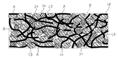
- this electrode has a nonwoven fabric current collector 10 made of aluminum or copper short fibers A having an average wire diameter of 100 ⁇ m or less, and a nonwoven fabric current collector 10 held by a binder B and charged.
- FIG. 1 is a diagram for clearly showing the configuration of the present embodiment.
- the sizes, thicknesses, lengths, and the like of the short fiber A, the active material powder 20, the conductive auxiliary agent 30, the carbon fiber CF, and the like are actually shown. And different.
- the nonwoven fabric-like current collector 10 it is also possible to make the nonwoven fabric-like current collector 10 hold an adsorbent powder that adsorbs electrolyte ions during charging, instead of the active material powder 20.
- the short fibers A of aluminum or copper have an average length of 25 mm, preferably 20 mm or less, and an average wire diameter of 30 ⁇ m or less, preferably 25 ⁇ m or less.
- the short fiber A of aluminum or copper is formed by chatter vibration cutting by applying a cutting tool to an aluminum or copper columnar member having a circular cross section, for example. It is also possible to form aluminum or copper short fibers having the wire diameter or length by other methods.
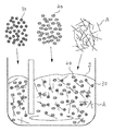
- the liquid or gel-like slurry S containing the short fiber A of aluminum or copper, the active material powder 20 that chemically reacts during charging and discharging, the conductive auxiliary agent 30, and the binder B is prepared.
- the slurry S is prepared by kneading a mixture of aluminum or copper short fibers A, active material powder 20, conductive auxiliary agent 30, and diluted binder B. Since the aluminum or copper short fiber A is a short fiber having a length of 25 mm or less, the aluminum or copper short fiber A, the active material powder 20 and the conductive additive 30 are easily mixed in the slurry S.
- pre-drying is performed to increase the viscosity of the slurry S.
- Pre-drying is to dry the binder B until it is not completely cured, thereby making it easier to form the slurry S into a predetermined shape.
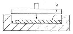
- the slurry S is put in a mold and the slurry S is pressurized. Thereby, the slurry S is formed into a predetermined thickness or the like according to the size of the electrode.
- a drying step of drying the formed slurry S by vacuum drying or the like is performed.
- the binder B in the slurry S is cured, and the active material powder 20 and the conductive additive 30 in the slurry are held by the short fibers A of the nonwoven fabric current collector 10 by the binder B.
- a pressurization process the process which passes the nonwoven fabric collector 10 between a pair of rollers, the process which pinches
- the purity is 99.9% or more, and more preferably, the purity is 99.99% or more.
- the two fibers A intersecting each other are bitten into each other at the portion where the fibers A are in contact with each other. It is possible to deform it. In other words, the fibers A are flattened at the contacted portion, and thereby, the two intersecting fibers A seem to bite each other.
- the slurry S containing the active material powder 20 it is also possible to create a slurry S containing adsorbent material powder that adsorbs electrolyte ions during charging instead of the active material powder 20.
- the adsorbent powder is held in place of the active material powder 20 on the short fibers A of the nonwoven fabric current collector 10 after the drying step.
- the active material powder 20 may be any material that can be held on the nonwoven fabric current collector 10 by the binder B or the like, and preferably has excellent cycle characteristics.
- the active material include lithium cobaltate (LiCoO 2 ), iron phosphate-based active materials, and carbon materials such as graphite.
- LiCoO 2 lithium cobaltate
- iron phosphate-based active materials iron phosphate-based active materials
- carbon materials such as graphite.
- the adsorbent powder used in place of the active material powder 20 may be any powder that can be held on the nonwoven fabric current collector 10 by the binder B or the like, and preferably has excellent cycle characteristics.
- adsorbent powders include polyacene (PAS), polyaniline (PAN), activated carbon, carbon black, graphite, and carbon nanotube.
- PAS polyacene
- PAN polyaniline
- activated carbon carbon black
- graphite graphite
- carbon nanotube carbon nanotube
- the active material powder 20 and the adsorbent powder are preferably pulverized using a mortar, ball mill, vibration ball mill, or the like, so that the average particle size is a predetermined value or less.
- a predetermined value the value etc. which added 10 micrometers to the average wire diameter of the short fiber A of the nonwoven fabric-form collector 10 are considered.
- the average particle diameter of the active material powder 20 and the adsorbent powder is 30 ⁇ m or less.
- binder B a thermoplastic resin, a polysaccharide polymer material, or the like can be used.
- the material of the binder include polyacrylic resin, polytetrafluoroethylene (PTFE), polyvinylidene fluoride (PVdF), a copolymer of vinylidene fluoride (VdF) and hexafluoropropylene (HFP), and the like.
- PTFE polytetrafluoroethylene
- PVdF polyvinylidene fluoride
- HFP hexafluoropropylene
- the conductive auxiliary agent 30 may be a material having conductivity, and is preferably a material that does not chemically change with an electrolyte or a solvent. Examples of the conductive aid 30 include graphite and carbon black. In addition, it is possible to use the well-known conductive support agent used for an electrode of a secondary battery or an electric double layer capacitor.
- the electrode made as described above can be used as an electrode of an electricity storage device such as an electric double layer capacitor, a secondary battery, a hybrid capacitor including a lithium ion capacitor.
- an electricity storage device such as an electric double layer capacitor, a secondary battery, a hybrid capacitor including a lithium ion capacitor.
- it can be used for a positive electrode and a negative electrode of an electric double layer capacitor, can be used for a positive electrode and a negative electrode of a lithium ion secondary battery as an example of a secondary battery, and is used for a positive electrode and a negative electrode of a lithium ion capacitor. It is possible. An application example thereof will be described later.
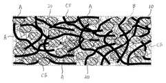
- the slurry S includes a slurry of carbon fiber CF having an average thickness of 0.5 ⁇ m or less, preferably 0.3 ⁇ m or less. It is also possible to use. In this case, as shown in FIG. 5, the carbon fibers CF are arranged in the gaps formed in the nonwoven fabric current collector 10.
- the carbon fibers CF are in contact with the short fibers A, the active material powder 20, the conductive additive 30, and other carbon fibers CF.
- carbon fibers CF having an average thickness of about 0.1 to 0.2 ⁇ m and a length of about 20 to 200 ⁇ m are used.
- the resistivity of the carbon-based conductive additive 30 is 0.1 to 0.3 ⁇ ⁇ cm, whereas the resistivity of the carbon fiber CF is, for example, 5 ⁇ 10 ⁇ 5 ⁇ ⁇ cm.
- the active material powder 20 and the short fiber A are electrically connected via the carbon fiber CF.
- the electrical resistance between the active material powder 20 and the short fiber A is further reduced due to the connection by the carbon fiber CF.
- the carbon fiber CF having good conductivity can reduce the resistance of movement of electrons between the active material powder 20 and the short fibers A, and the resistance to the movement of electrons to the input / output terminals can be reduced. It is advantageous.
- the carbon fibers CF are arranged in the gaps formed in the nonwoven fabric-like current collector 10, and the configuration has an electrical resistance between the active material powder 20 and the short fibers A.
- 5 and 6 are diagrams for easy understanding of the configuration of the present embodiment. The size, thickness, and length of the short fiber A, the active material powder 20, the conductive auxiliary agent 30, the carbon fiber CF, and the like are illustrated. May differ from actual.
- the average length of the carbon fibers CF is preferably at least half of the average particle diameter of the active material powder 20 or the adsorbent powder, and the average particle diameter is 2 / 3 or more is more preferable.
- FIG. 7 shows an example of a coin-type secondary battery using the electrode of this embodiment.
- the coin-type secondary battery includes a case (exterior can) 100 having a case main body 102 and a lid 101, and a power storage unit housed in the case 100.
- the power storage unit includes an electrode using the short fiber A made of aluminum according to the present embodiment as the positive electrode 110.
- the negative electrode 120 facing the positive electrode 110 and the separator 130 disposed between the positive electrode 110 and the negative electrode 120 are included.
- the positive electrode 110 is in surface contact with the case main body 102
- the negative electrode 120 is in surface contact with the lid 101, whereby the lid 101 and the case main body 102 function as input / output terminals of the positive electrode 110 and the negative electrode 120.
- the non-woven current collector 10 used for the positive electrode 110 holds the active material powder 20 for the positive electrode.
- the negative electrode 120 only needs to have the structure and material of a known negative electrode of a secondary battery.
- a carbon material such as graphite is used as an active material
- a copper is used as a current collector.
- a foil is used.
- the separator 130 may be any material as long as it electrically insulates the positive electrode 110 and the negative electrode 120, has ion permeability, and has resistance to oxidation / reduction at the contact surface between the positive electrode 110 and the negative electrode 120.
- a porous polymer, an inorganic material, an organic / inorganic hybrid material, glass fiber, or the like can be used.
- the case 100 containing the power storage unit is filled with an electrolytic solution.
- a lithium salt, potassium salt, sodium salt, magnesium salt, or the like can be used as the electrolyte of the electrolytic solution.
- a lithium salt is used in the case of a lithium ion secondary battery.
- a non-aqueous solvent is used as a solvent in which the electrolyte dissolves, and ethylene carbonate, propylene carbonate, dimethyl carbonate, diethyl carbonate, carbonate ester, and the like can be used as the non-aqueous solvent.
- one surface in the thickness direction of the nonwoven fabric current collector 10 used for the positive electrode 110 is in contact with the case main body 102.
- the nonwoven fabric current collector 10 used for the positive electrode 110 is filled with the active material powder 20 in the entire range from one surface in the thickness direction to the other surface. It is in contact with the short fibers A of the nonwoven fabric current collector 10. For this reason, the distance between the short fiber A carrying the electrons to the input / output terminal and the active material powder 20 becomes close, which is advantageous in improving the charge / discharge rate.
- the active material powder 20 and the short fibers A are in direct contact, or the active material powder 20 and the short fibers A are disposed close to each other and are electrically connected via the conductive auxiliary agent 30 and the like. Therefore, when electrons are exchanged between the active material powder 20 and the short fibers A, the resistance of the electrons moving to the input / output terminals provided at the ends of the nonwoven fabric current collector 10 is reduced. be able to.
- the coin-type secondary battery includes a positive electrode 140 having a current collector 141 made of aluminum foil and an electrode layer 142 applied to one surface in the thickness direction of the current collector 141.
- the electrode layer 142 contains active material powder, a conductive aid, a binder, and the like. Since the coin-type secondary battery has a limited space, the amount of active material powder in the conventional coin-type secondary battery is limited by the thickness of the current collector 141. Moreover, since the electrons of the active material powder arranged on the separator 130 side move to the current collector 141 via the active material powder and the conductive auxiliary agent arranged between the current collector 141, the charge / discharge speed is increased. It is not preferable for improvement.
- the electrode structure of this embodiment particularly an electrode using short fibers A made of copper can be used for the negative electrode 120.
- the current collector of this electrode is a non-woven current collector 10, and a carbon material is used as the active material powder 20.
- lithium titanate, titanium oxide, tungsten oxide, tin oxide, etc. May be used.
- the electrode structure using the aluminum or copper short fibers A of the present embodiment is used only for the positive electrode, as in the coin-type secondary battery. It can be used only for the negative electrode and for both the positive electrode and the negative electrode.
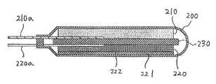
- FIG. 9 shows an example of an electric double layer capacitor using the electrode of this embodiment.
- the electric double layer capacitor includes, for example, a container 200 and a power storage unit accommodated in the container 200.
- the power storage unit includes an electrode using the aluminum short fiber A of the present embodiment as the positive electrode 210.
- a negative electrode 220 that opposes the positive electrode 210 and a separator 230 that is disposed between the positive electrode 210 and the negative electrode 220 are provided.
- a positive electrode input / output terminal 210 a is connected to the positive electrode 210, and a negative electrode input / output terminal 220 a is similarly connected to the negative electrode 220, and each input / output terminal extends to the outside of the container 200.
- the adsorbent powder is held in the nonwoven fabric current collector 10 used for the positive electrode 210.
- the negative electrode 220 only needs to have the structure and material of a negative electrode of a known electric double layer capacitor.
- the current collector 221 made of aluminum foil and the current collector are coated on one surface in the thickness direction.
- an electrode layer 222 contains adsorbent powder, a conductive aid, a binder, and the like.
- the separator 230 may be any material as long as it electrically insulates the positive electrode 210 and the negative electrode 220, has ion permeability, and has resistance to oxidation / reduction at the contact surface between the positive electrode 210 and the negative electrode 220.
- a porous polymer, an inorganic material, an organic / inorganic hybrid material, glass fiber, or the like can be used.
- the container 200 containing the power storage unit is filled with an electrolytic solution.
- the electrolytic solution contains a non-aqueous solvent and an electrolyte.
- the electrolyte and the non-aqueous solvent may be any known substance used for electric double layer capacitors.
- ammonium salts and phosphonium salts can be used as the electrolyte
- cyclic carbonates, chain carbonates, cyclic esters, chain esters, cyclic ethers, chain ethers, nitriles, sulfur-containing compounds, etc. can be used as non-aqueous solvents. it can.
- one end of the nonwoven fabric current collector 10 used for the positive electrode 210 is connected to the positive electrode input / output terminal 210a. Further, the non-woven current collector 10 used for the positive electrode 210 is filled with the adsorbent powder in the entire range from one surface in the thickness direction to the other surface, and a lot of the adsorbent powder is in the form of non-woven fabric. It is in contact with the short fiber A of the current collector 10. For this reason, the distance between the short fiber A carrying the electrons to the positive electrode input / output terminal 210a and the adsorbent powder is reduced, which is advantageous in improving the charge / discharge rate.
- the structure of the conventional positive electrode is the same as that of the negative electrode 220, it is easier to understand the advantages compared to the negative electrode 220.
- the electrode structure using the aluminum short fiber A of the present embodiment for the negative electrode 220 it is also possible to use the structure of the electrode which uses the copper short fiber A of this embodiment for the positive electrode 210 and the negative electrode 220.
- the electrode of the electricity storage device in which the active material powder 20 and the adsorbent powder are arranged in the vicinity of the high-purity aluminum short fiber A and the copper short fiber A. is there. As a result, it is possible to manufacture an electricity storage device having higher capacity, less deformation resistance, and excellent charge / discharge characteristics.
- the manufacture of aluminum foil used in ordinary capacitors and secondary batteries, etc. made a very large square column aluminum ingot called slab, cut, heated and rolled many times, Manufactured with surface treatment. This requires a great deal of energy and cost.
- the aluminum or copper short fibers A used in the present embodiment can be manufactured by chatter vibration cutting or the like.
- the press pressure can be reduced. For this reason, it becomes possible to manufacture a collector foil and a positive electrode foil easily and at low cost without requiring a large facility.
- the short fibers A of aluminum or copper are electrically connected to each other, and the non-woven current collector is connected to the short fibers A of aluminum or copper. 10 is formed. Moreover, since the short fiber A of aluminum or copper and the adsorbent powder or active material powder 20 are mixed in the slurry S, when the slurry S is dried, the short fiber A of the nonwoven fabric current collector 10 is interposed between the short fibers A. The adsorbent powder or active material powder 20 enters the formed gap.
- the adsorbent powder or active material powder 20 is in direct contact with the short fibers A, or is arranged in the vicinity of the short fibers A, and exchange of electrons between the adsorbent powder or active material powder 20 and the short fibers A is performed. When this is performed, the movement resistance can be reduced.
- the carbon fiber CF is mixed with the slurry S, even when the adsorbent powder or active material powder 20 and the short fiber A are not in direct contact with each other when the electrode is formed, the adsorbent powder or active material is used.
- the powder 20 and the short fiber A are electrically connected through the carbon fiber CF. Further, even when the adsorbent powder or active material powder 20 and the short fiber A are in direct contact, the electricity between the adsorbent powder or active material powder 20 and the short fiber A due to the connection by the carbon fiber. Resistance is further reduced.
- Nonwoven fabric collector 20
- Active material powder 30
- Conductive auxiliary agent A Aluminum or copper short fiber
- Binder S Slurry CF Carbon fiber
Landscapes
- Engineering & Computer Science (AREA)
- Chemical & Material Sciences (AREA)
- Power Engineering (AREA)
- Chemical Kinetics & Catalysis (AREA)
- Electrochemistry (AREA)
- General Chemical & Material Sciences (AREA)
- Materials Engineering (AREA)
- Microelectronics & Electronic Packaging (AREA)
- Manufacturing & Machinery (AREA)
- Composite Materials (AREA)
- Cell Electrode Carriers And Collectors (AREA)
- Battery Electrode And Active Subsutance (AREA)
- Electric Double-Layer Capacitors Or The Like (AREA)
Priority Applications (4)
| Application Number | Priority Date | Filing Date | Title |
|---|---|---|---|
| EP17883809.0A EP3561917B1 (en) | 2016-12-22 | 2017-12-19 | Electrode for power storage devices and production method for said electrode |
| KR1020197021509A KR102392582B1 (ko) | 2016-12-22 | 2017-12-19 | 축전 장치의 전극 및 그 제조 방법 |
| CN201780079972.6A CN110114915B (zh) | 2016-12-22 | 2017-12-19 | 蓄电装置的电极及其制造方法 |
| US16/445,393 US11367576B2 (en) | 2016-12-22 | 2019-06-19 | Electrode for power storage devices and method of manufacturing the same |
Applications Claiming Priority (2)
| Application Number | Priority Date | Filing Date | Title |
|---|---|---|---|
| JP2016-249763 | 2016-12-22 | ||
| JP2016249763A JP6670231B2 (ja) | 2016-12-22 | 2016-12-22 | 蓄電デバイスの電極、蓄電デバイスの電極用のスラリーおよびその製造方法 |
Related Child Applications (1)
| Application Number | Title | Priority Date | Filing Date |
|---|---|---|---|
| US16/445,393 Continuation US11367576B2 (en) | 2016-12-22 | 2019-06-19 | Electrode for power storage devices and method of manufacturing the same |
Publications (2)
| Publication Number | Publication Date |
|---|---|
| WO2018116151A2 true WO2018116151A2 (ja) | 2018-06-28 |
| WO2018116151A3 WO2018116151A3 (ja) | 2019-05-09 |
Family
ID=62626342
Family Applications (1)
| Application Number | Title | Priority Date | Filing Date |
|---|---|---|---|
| PCT/IB2017/058110 Ceased WO2018116151A2 (ja) | 2016-12-22 | 2017-12-19 | 蓄電デバイスの電極およびその製造方法 |
Country Status (6)
| Country | Link |
|---|---|
| US (1) | US11367576B2 (enExample) |
| EP (1) | EP3561917B1 (enExample) |
| JP (1) | JP6670231B2 (enExample) |
| KR (1) | KR102392582B1 (enExample) |
| CN (1) | CN110114915B (enExample) |
| WO (1) | WO2018116151A2 (enExample) |
Cited By (2)
| Publication number | Priority date | Publication date | Assignee | Title |
|---|---|---|---|---|
| CN113454808A (zh) * | 2019-02-20 | 2021-09-28 | 深圳智科微铝科技有限公司 | 使用了固体电解质的蓄电装置的电极、蓄电装置及蓄电装置的正极层或负极层的制造方法 |
| CN114127983A (zh) * | 2019-07-31 | 2022-03-01 | 深圳智科微铝科技有限公司 | 蓄电设备的电极的制造方法以及蓄电设备的电极 |
Families Citing this family (2)
| Publication number | Priority date | Publication date | Assignee | Title |
|---|---|---|---|---|
| US10854882B2 (en) * | 2018-10-19 | 2020-12-01 | GM Global Technology Operations LLC | Negative electrode for a lithium-ion electrochemical cell and method of forming same |
| JP7692588B2 (ja) * | 2019-07-31 | 2025-06-16 | I&Tニューマテリアルズ株式会社 | 蓄電デバイスの電極の製造方法および蓄電デバイスの電極 |
Citations (2)
| Publication number | Priority date | Publication date | Assignee | Title |
|---|---|---|---|---|
| JP2005086113A (ja) | 2003-09-10 | 2005-03-31 | Toyota Motor Corp | 電気二重層キャパシタ |
| JP2007123156A (ja) | 2005-10-31 | 2007-05-17 | Hitachi Maxell Ltd | リチウムイオン電池 |
Family Cites Families (31)
| Publication number | Priority date | Publication date | Assignee | Title |
|---|---|---|---|---|
| JPS6159716A (ja) | 1984-08-30 | 1986-03-27 | 松下電器産業株式会社 | 電気二重層キヤパシタ |
| JPH0740485B2 (ja) * | 1988-12-09 | 1995-05-01 | 松下電器産業株式会社 | リチウム二次電池用の正極合剤の製造法 |
| JPH06267542A (ja) * | 1993-03-12 | 1994-09-22 | Yuasa Corp | 非水電解液電池 |
| JPH09143510A (ja) * | 1995-11-14 | 1997-06-03 | Kataoka Tokushu Kogyo Kk | 電池電極基板用金属繊維多孔体、電池電極板およびその製造方法 |
| JPH10284055A (ja) * | 1997-02-04 | 1998-10-23 | Mitsubishi Electric Corp | リチウムイオン二次電池用電極およびそれを用いたリチウムイオン二次電池 |
| JPH11312523A (ja) * | 1998-04-28 | 1999-11-09 | Shin Kobe Electric Mach Co Ltd | 電池用電極及び非水電解液電池 |
| JP2000167721A (ja) * | 1998-12-03 | 2000-06-20 | Kogi Corp | 金属短繊維及びその製造方法 |
| JP3851041B2 (ja) * | 1999-12-22 | 2006-11-29 | 三洋電機株式会社 | 水素吸蔵合金電極 |
| CN1314142C (zh) * | 2005-09-15 | 2007-05-02 | 上海交通大学 | 水基流延工艺制备熔融碳酸盐燃料电池隔膜的方法 |
| JP2009016265A (ja) * | 2007-07-06 | 2009-01-22 | Showa Denko Kk | リチウム系電池用電極、リチウム系電池用電極の製造方法、リチウム系電池、及びリチウム系電池の製造方法 |
| JP5252535B2 (ja) * | 2007-09-03 | 2013-07-31 | Necエナジーデバイス株式会社 | 非水電解液二次電池 |
| JP2009151960A (ja) * | 2007-12-19 | 2009-07-09 | Toyota Motor Corp | リチウムイオン二次電池用正極電極体、及びリチウムイオン二次電池 |
| JP2009224623A (ja) | 2008-03-17 | 2009-10-01 | Nippon Zeon Co Ltd | ハイブリッドキャパシタ用電極シートおよびその製造方法 |
| JP5432746B2 (ja) * | 2010-01-28 | 2014-03-05 | 株式会社日立製作所 | リチウムイオン二次電池 |
| JP5783172B2 (ja) | 2010-05-25 | 2015-09-24 | 日本ゼオン株式会社 | 二次電池用正極及び二次電池 |
| JP2012230887A (ja) | 2011-04-15 | 2012-11-22 | Toshiba Corp | 導電性多孔質材料、燃料電池、電解セル |
| JP2013026444A (ja) * | 2011-07-21 | 2013-02-04 | Sumitomo Electric Ind Ltd | 非水電解質電気化学素子用電極の製造方法およびその非水電解質電気化学素子用電極を備えた非水電解質電気化学素子 |
| CN102306749B (zh) * | 2011-10-11 | 2013-12-25 | 北京化工大学 | 一种基于螺旋状碳纳米纤维束的薄膜电极及其制备方法 |
| JP5924925B2 (ja) * | 2011-12-16 | 2016-05-25 | 三星エスディアイ株式会社Samsung SDI Co., Ltd. | 二次電池用正極及び二次電池 |
| KR20130127859A (ko) * | 2012-05-15 | 2013-11-25 | 삼성에스디아이 주식회사 | 리튬 이차전지용 양극 슬러리 조성물 및 이를 포함하는 리튬이차전지 및 리튬이차전지의 제조방법 |
| CN102738469A (zh) * | 2012-07-11 | 2012-10-17 | 中国第一汽车股份有限公司 | 一种柔软型聚合物锂电池及其制备方法 |
| JP2014096238A (ja) * | 2012-11-08 | 2014-05-22 | Fuji Heavy Ind Ltd | 蓄電デバイス用正極の製造方法、及び正極 |
| KR101511984B1 (ko) * | 2012-12-06 | 2015-04-14 | 한국표준과학연구원 | 구리산화물 나노구조체의 제조방법 및 리튬이온 이차전지용 음극의 제조방법 |
| JP2014191919A (ja) * | 2013-03-26 | 2014-10-06 | Mitsubishi Materials Corp | リチウムイオン二次電池用正極及びその製造方法 |
| US9490472B2 (en) * | 2013-03-28 | 2016-11-08 | Semiconductor Energy Laboratory Co., Ltd. | Method for manufacturing electrode for storage battery |
| JP6197384B2 (ja) | 2013-06-06 | 2017-09-20 | 日立化成株式会社 | リチウムイオン二次電池用の正極及びその製造方法 |
| WO2015083262A1 (ja) * | 2013-12-05 | 2015-06-11 | 株式会社日立製作所 | リチウムイオン二次電池用負極材料及びその製造方法、リチウムイオン二次電池用負極及びその製造方法並びにリチウムイオン二次電池 |
| KR101817827B1 (ko) * | 2014-12-29 | 2018-01-11 | 주식회사 엘지화학 | 이차전지용 양극 및 이를 포함하는 리튬 이차전지 |
| CN104617336B (zh) * | 2015-02-12 | 2017-04-19 | 中国工程物理研究院化工材料研究所 | 一种线性柔性的锂离子电池及其制备方法 |
| CN107431185B (zh) * | 2015-03-27 | 2020-10-27 | 日产自动车株式会社 | 锂离子电池用电极、锂离子电池以及锂离子电池用电极的制造方法 |
| WO2016159389A1 (ja) * | 2015-03-31 | 2016-10-06 | 株式会社巴川製紙所 | 低抵抗金属繊維シート及びその製造方法 |
-
2016
- 2016-12-22 JP JP2016249763A patent/JP6670231B2/ja active Active
-
2017
- 2017-12-19 KR KR1020197021509A patent/KR102392582B1/ko active Active
- 2017-12-19 CN CN201780079972.6A patent/CN110114915B/zh active Active
- 2017-12-19 WO PCT/IB2017/058110 patent/WO2018116151A2/ja not_active Ceased
- 2017-12-19 EP EP17883809.0A patent/EP3561917B1/en active Active
-
2019
- 2019-06-19 US US16/445,393 patent/US11367576B2/en active Active
Patent Citations (2)
| Publication number | Priority date | Publication date | Assignee | Title |
|---|---|---|---|---|
| JP2005086113A (ja) | 2003-09-10 | 2005-03-31 | Toyota Motor Corp | 電気二重層キャパシタ |
| JP2007123156A (ja) | 2005-10-31 | 2007-05-17 | Hitachi Maxell Ltd | リチウムイオン電池 |
Non-Patent Citations (1)
| Title |
|---|
| See also references of EP3561917A4 |
Cited By (4)
| Publication number | Priority date | Publication date | Assignee | Title |
|---|---|---|---|---|
| CN113454808A (zh) * | 2019-02-20 | 2021-09-28 | 深圳智科微铝科技有限公司 | 使用了固体电解质的蓄电装置的电极、蓄电装置及蓄电装置的正极层或负极层的制造方法 |
| CN114127983A (zh) * | 2019-07-31 | 2022-03-01 | 深圳智科微铝科技有限公司 | 蓄电设备的电极的制造方法以及蓄电设备的电极 |
| EP4007008A4 (en) * | 2019-07-31 | 2022-09-21 | Shenzhen I&T Micro Aluminium Technology Co., Ltd. | METHOD OF MANUFACTURE OF ELECTRODE FOR POWER STORAGE DEVICE AND ELECTRODE FOR POWER STORAGE DEVICE |
| CN114127983B (zh) * | 2019-07-31 | 2024-08-09 | 深圳智科微铝科技有限公司 | 蓄电设备的电极的制造方法以及蓄电设备的电极 |
Also Published As
| Publication number | Publication date |
|---|---|
| US11367576B2 (en) | 2022-06-21 |
| KR102392582B1 (ko) | 2022-05-04 |
| EP3561917B1 (en) | 2022-03-16 |
| US20190304709A1 (en) | 2019-10-03 |
| JP6670231B2 (ja) | 2020-03-18 |
| WO2018116151A3 (ja) | 2019-05-09 |
| EP3561917A2 (en) | 2019-10-30 |
| JP2018106846A (ja) | 2018-07-05 |
| KR20190121755A (ko) | 2019-10-28 |
| CN110114915B (zh) | 2022-06-10 |
| CN110114915A (zh) | 2019-08-09 |
| EP3561917A4 (en) | 2019-12-25 |
Similar Documents
| Publication | Publication Date | Title |
|---|---|---|
| JP5721845B2 (ja) | 金属長纎維を含む電極構造を有する電池及びその製造方法 | |
| JP6003041B2 (ja) | 耐熱絶縁層付セパレータ | |
| CN101546829A (zh) | 负极用碳材料、蓄电装置、以及蓄电装置搭载品 | |
| US11367576B2 (en) | Electrode for power storage devices and method of manufacturing the same | |
| JP2012004491A (ja) | 蓄電デバイス | |
| JP5169720B2 (ja) | 電気化学素子用電極の製造方法および電気化学素子 | |
| JP7609432B2 (ja) | 蓄電デバイスの電極およびその製造方法 | |
| CN108028389B (zh) | 蓄电设备的集电体用铝非织造纤维材料及其制造方法、利用所述铝非织造纤维材料的电极及其制造方法 | |
| JP2011119290A (ja) | 電気化学素子用電極の製造方法 | |
| KR102028677B1 (ko) | 그래핀 전극을 적용한 적층형 리튬 이온 커패시터 | |
| JP2002043180A (ja) | 電気二重層コンデンサ | |
| CN114127983B (zh) | 蓄电设备的电极的制造方法以及蓄电设备的电极 | |
| US12400805B1 (en) | Hybrid electrochemical energy storage system with high energy density and high power density | |
| JP7751011B1 (ja) | 正極、固体電池及び固体電池の製造方法 | |
| JP7692588B2 (ja) | 蓄電デバイスの電極の製造方法および蓄電デバイスの電極 | |
| RU2581849C2 (ru) | Литий-углеродный электрохимический конденсатор и способ его изготовления | |
| JP2008016381A (ja) | 電池用電極 | |
| JP2008182023A (ja) | 電気二重層キャパシタ | |
| JP2022114318A (ja) | 蓄電デバイスの電極の製造方法、蓄電デバイスの電極用の短繊維の製造方法、容器に入った蓄電デバイスの電極用の短繊維、および蓄電デバイスの電極 |
Legal Events
| Date | Code | Title | Description |
|---|---|---|---|
| NENP | Non-entry into the national phase |
Ref country code: DE |
|
| ENP | Entry into the national phase |
Ref document number: 20197021509 Country of ref document: KR Kind code of ref document: A |
|
| ENP | Entry into the national phase |
Ref document number: 2017883809 Country of ref document: EP Effective date: 20190722 |
|
| 121 | Ep: the epo has been informed by wipo that ep was designated in this application |
Ref document number: 17883809 Country of ref document: EP Kind code of ref document: A2 |