WO2018110134A1 - 車載制御装置 - Google Patents
車載制御装置 Download PDFInfo
- Publication number
- WO2018110134A1 WO2018110134A1 PCT/JP2017/039686 JP2017039686W WO2018110134A1 WO 2018110134 A1 WO2018110134 A1 WO 2018110134A1 JP 2017039686 W JP2017039686 W JP 2017039686W WO 2018110134 A1 WO2018110134 A1 WO 2018110134A1
- Authority
- WO
- WIPO (PCT)
- Prior art keywords
- voltage
- current
- control device
- unit
- disconnection
- Prior art date
- Legal status (The legal status is an assumption and is not a legal conclusion. Google has not performed a legal analysis and makes no representation as to the accuracy of the status listed.)
- Ceased
Links
Images

Classifications
-
- G—PHYSICS
- G01—MEASURING; TESTING
- G01R—MEASURING ELECTRIC VARIABLES; MEASURING MAGNETIC VARIABLES
- G01R31/00—Arrangements for testing electric properties; Arrangements for locating electric faults; Arrangements for electrical testing characterised by what is being tested not provided for elsewhere
- G01R31/50—Testing of electric apparatus, lines, cables or components for short-circuits, continuity, leakage current or incorrect line connections
- G01R31/54—Testing for continuity
-
- B—PERFORMING OPERATIONS; TRANSPORTING
- B60—VEHICLES IN GENERAL
- B60R—VEHICLES, VEHICLE FITTINGS, OR VEHICLE PARTS, NOT OTHERWISE PROVIDED FOR
- B60R16/00—Electric or fluid circuits specially adapted for vehicles and not otherwise provided for; Arrangement of elements of electric or fluid circuits specially adapted for vehicles and not otherwise provided for
- B60R16/02—Electric or fluid circuits specially adapted for vehicles and not otherwise provided for; Arrangement of elements of electric or fluid circuits specially adapted for vehicles and not otherwise provided for electric constitutive elements
-
- G—PHYSICS
- G01—MEASURING; TESTING
- G01R—MEASURING ELECTRIC VARIABLES; MEASURING MAGNETIC VARIABLES
- G01R31/00—Arrangements for testing electric properties; Arrangements for locating electric faults; Arrangements for electrical testing characterised by what is being tested not provided for elsewhere
- G01R31/005—Testing of electric installations on transport means
- G01R31/006—Testing of electric installations on transport means on road vehicles, e.g. automobiles or trucks
-
- H—ELECTRICITY
- H02—GENERATION; CONVERSION OR DISTRIBUTION OF ELECTRIC POWER
- H02H—EMERGENCY PROTECTIVE CIRCUIT ARRANGEMENTS
- H02H1/00—Details of emergency protective circuit arrangements
- H02H1/0007—Details of emergency protective circuit arrangements concerning the detecting means
-
- H—ELECTRICITY
- H02—GENERATION; CONVERSION OR DISTRIBUTION OF ELECTRIC POWER
- H02H—EMERGENCY PROTECTIVE CIRCUIT ARRANGEMENTS
- H02H1/00—Details of emergency protective circuit arrangements
- H02H1/04—Arrangements for preventing response to transient abnormal conditions, e.g. to lightning or to short duration over voltage or oscillations; Damping the influence of DC component by short circuits in AC networks
-
- H—ELECTRICITY
- H02—GENERATION; CONVERSION OR DISTRIBUTION OF ELECTRIC POWER
- H02H—EMERGENCY PROTECTIVE CIRCUIT ARRANGEMENTS
- H02H3/00—Emergency protective circuit arrangements for automatic disconnection directly responsive to an undesired change from normal electric working condition with or without subsequent reconnection ; integrated protection
- H02H3/38—Emergency protective circuit arrangements for automatic disconnection directly responsive to an undesired change from normal electric working condition with or without subsequent reconnection ; integrated protection responsive to both voltage and current; responsive to phase angle between voltage and current
-
- H—ELECTRICITY
- H02—GENERATION; CONVERSION OR DISTRIBUTION OF ELECTRIC POWER
- H02H—EMERGENCY PROTECTIVE CIRCUIT ARRANGEMENTS
- H02H3/00—Emergency protective circuit arrangements for automatic disconnection directly responsive to an undesired change from normal electric working condition with or without subsequent reconnection ; integrated protection
- H02H3/02—Details
- H02H3/033—Details with several disconnections in a preferential order, e.g. following priority of the users, load repartition
Definitions
- the present invention relates to an in-vehicle control device mounted on a vehicle.
- Patent Document 1 There is a technique described in Patent Document 1 as a technique for detecting an open failure of a single ground terminal.
- An object of the present invention is an in-vehicle control device having a single ground terminal, which avoids erroneous detection due to a temporary voltage abnormality or current abnormality, and can accurately detect a disconnection failure of a ground wiring. Is to realize.
- the present invention is configured as follows.
- a disconnection detector Based on the correlation between the current measured by the current monitor unit and the voltage measured by the voltage monitor unit, it is determined whether or not the ground terminal connected to the negative terminal of the battery has an open failure.
- an in-vehicle control device having a single ground terminal, which can avoid erroneous detection due to a temporary voltage abnormality or current abnormality, and can accurately detect a disconnection failure of the ground wiring. Can be realized.
- FIG. 1 is a schematic configuration diagram of a transmission system for a vehicle to which the present invention is applied. It is an internal block diagram of ECU (control apparatus) shown in FIG. It is a figure explaining the electric current which flows into the drive part 65 inside the control apparatus 6 in the state which the ground terminal 72 of the control apparatus 6 is connected, and the state which has disconnected. It is a graph which shows the relationship between the electric current change which flows into a shunt resistance, and the plus side voltage change of the electrolytic capacitor for smoothing in the case where it changes into the state where the ground wiring was disconnected. It is a functional block diagram regarding the disconnection detection by Example 1 of this invention. It is a functional block diagram regarding the disconnection detection by Example 2 of this invention. It is a functional block diagram regarding the disconnection detection by Example 3 of this invention. It is principle explanatory drawing of the ground wiring disconnection detection in Example 3 of this invention. It is an operation
- the negative electrode (minus terminal) of the battery 73 arranged outside the control device 6 is connected to the ground, and the positive electrode (plus terminal) of the battery 73 is connected to the power supply terminal 71 of the control device 6.
- the power terminal 71 is connected to one end of the smoothing electrolytic capacitor 64 via the power relay 63 and also connected to the drive circuit 66.
- the other end of the smoothing electrolytic capacitor 64 is connected to circuit ground. Therefore, the smoothing electrolytic capacitor 64 is connected between the drive circuit (switch element) 66 and the circuit ground 74.
- the drive circuit 66 is supplied with a positive voltage from the battery 73 and is connected to the output terminal (load terminal) 70 via the cathode of the regenerative current diode 68 and the shunt resistor 69.
- the microcomputer 62 supplies an energization cutoff signal to the power supply relay 63 to control the energization cutoff of the power supply relay 63.
- the microcomputer 62 supplies an on / off signal to the drive circuit 66, and the drive circuit 66 is driven by controlling the energization current of the linear solenoid 5.
- the drive of the linear solenoid 5 by the drive circuit 66 is stopped.
- the microcomputer 62 monitors the voltage (positive side voltage) at one end of the smoothing electrolytic capacitor 64, that is, the terminal connected to the power supply relay 63 of the smoothing electrolytic capacitor 64. That is, the microcomputer 62 is connected to the circuit ground 74 and monitors the voltage across the smoothing electrolytic capacitor 64.
- the negative electrode of the battery 73 is connected to the circuit ground 74 inside the control device 6 via the ground line 72L and the ground terminal 72.
- the drive unit 65 includes a drive circuit 66, a differential amplifier 67, a regenerative current diode 68, and a shunt resistor 69.
- the microcomputer 62 supplies an on / off signal to the drive circuit 66 as described above, and while the on signal is output, the microcomputer 62 of FIG. A current flows through the path to the linear solenoid 5.
- the off signal is output after the on signal is output, the current flows to the linear solenoid 5 through the path (b) of FIG. 2-1.
- the voltage across the smoothing electrolytic capacitor 64 is equivalent to the voltage of the battery 73.
- a smoothing electrolytic capacitor 64, a drive circuit 66, a regenerative current diode 68, and a linear solenoid 5 constitute a booster circuit.
- the on signal of the microcomputer 62 is output, a current flows through the same path as in FIG.
- the off signal is output after the on signal is output, the current flows to the linear solenoid 5 through the path (c) in FIG.
- the voltage across the electrolytic capacitor 64 for smoothing rises due to the current in the path (c). That is, depending on the current flowing through the linear solenoid 5, the voltage across the smoothing electrolytic capacitor 64 increases.
- FIG. 3 shows a change in the current flowing through the shunt resistor 69 detected by the microcomputer 62 when the ground wiring 72L connected to the ground terminal 72 is disconnected from the disconnected state (open failure) (FIG. 3).
- (B)) is a graph showing the correlation between the voltage change at both ends of the smoothing electrolytic capacitor 64 ((a) of FIG. 3).
- the control device 6 performs current control in order to control the linear solenoid 5.
- the voltage instantaneously increases from V0 to a voltage V1 greater than V0. Based on the control state of the transmission, when the current is increased from the time t3 after the time t2, the current value I1 is obtained at the time t7. Similarly to the current, the voltage also increases in a slope at time t3 after time t2 and reaches a voltage value V2 at time t7.
- the disconnection determination is performed at regular time intervals.
- the voltage value monitored at time t4 falls within the range of threshold 1
- the voltage value monitored at time t5 falls within the range of threshold 2
- monitored at time t6 When the voltage value falls within the range of the threshold value 3, it is determined that the ground wiring 72L is disconnected (open failure of the ground terminal 72).
- the upper limit and lower limit of the voltage range threshold can be set in consideration of the characteristics of the device used and the usage environment.
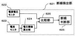
- FIG. 4 is a functional block diagram relating to disconnection detection of the microcomputer 62 shown in FIG.
- the functional block relating to disconnection detection of the microcomputer 62 includes a power supply voltage monitor unit 622, a current monitor unit 623, and a disconnection detection unit 621.
- the disconnection detection unit 621 includes a voltage threshold value calculation unit 624, a comparison unit 625, and a disconnection determination unit 626.
- the power supply voltage monitor unit 622 monitors (measures) the positive voltage of the smoothing electrolytic capacitor 64 and outputs the monitored voltage value to the comparison unit 625.
- the current monitoring unit 623 monitors (measures) the current flowing through the shunt resistor 69, that is, the current flowing through the linear solenoid 5 based on the signal output from the differential amplifier 67 shown in FIG. The value is output to the voltage threshold calculation unit 624.
- the voltage threshold value calculation unit 624 calculates a voltage threshold value (voltage range) based on the current value from the current monitor unit 623 using a predetermined calculation formula or the like, and outputs the voltage threshold value (voltage range) to the comparison unit 625.
- the disconnection determination unit 626 determines whether or not the ground wiring 72L is disconnected by the determination method described above based on the output signal from the comparison unit 625.
- the drive signal supplied from the microcomputer 62 to the drive circuit 66 is turned off, and the drive of the linear solenoid 5 of the drive unit 65 is stopped.
- the current flowing through the shunt resistor 69 is monitored, and the positive side electrode of the smoothing electrolytic capacitor 64 when the ground wiring 72L is disconnected based on the monitored current value.
- the voltage range (voltage threshold) is calculated.
- the voltage of the positive electrode of the smoothing electrolytic capacitor 64 is monitored, and the current range that flows in the shunt resistor 69 when the ground wiring 72L is disconnected based on the monitored voltage value ( Current threshold value) is calculated, and the calculated current threshold value is compared with the current flowing through the monitored shunt resistor 69 to determine whether or not the ground wiring 72L is disconnected.
- the current value monitored at time t4 falls within the first current threshold range in the current waveform shown in FIG. 3B
- the current value monitored at time t5 is further changed.
- the current value monitored at the time point t6 falls within the range of the second current threshold and falls within the range of the third current threshold, it is determined that the ground wiring 72L is disconnected.
- the difference between the example shown in FIG. 5 and the example shown in FIG. 4 is that the voltage threshold value calculation unit 624 in FIG. 4 is deleted and the output value (current value) from the current monitor 623 is output to the comparison unit 625.
- the comparison unit 625 compares the current value output from the current monitoring unit 623 with the upper and lower limit values of the voltage threshold (voltage range) output from the current threshold calculation unit 627, and the monitored current value is within the current threshold. It is determined whether or not. If the current value falls within the current threshold value, a signal indicating that is output to the disconnection determination unit 626.
- the disconnection determination unit 626 determines whether or not the ground wiring 72L is disconnected by the determination method described above based on the output signal from the comparison unit 625.
- the drive signal supplied from the microcomputer 62 to the drive circuit 66 is turned off, and the drive of the linear solenoid 5 of the drive unit 65 is stopped.
- the disconnection of the ground wiring 72L indicates that the voltage of the positive electrode of the smoothing electrolytic capacitor 64 and the current flowing through the shunt resistor 69 (current flowing through the linear solenoid 5)) Judgment based on the correlation.
- the voltage waveform of the positive electrode of the smoothing electrolytic capacitor 64 and the shunt resistance Focusing on the fact that a difference occurs in the waveform of the current flowing through 69, it is determined that the ground wiring 72L is disconnected.
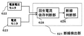
- FIG. 6 is a functional block diagram relating to disconnection detection of the microcomputer 62 shown in FIG. 2 in the third embodiment
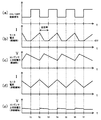
- FIG. 7 is an explanatory diagram of the principle of detection of disconnection of the ground wiring 72L in the third embodiment.
- FIG. 7A shows the waveform of the drive signal (ON / OFF control signal) supplied to the drive circuit 66
- FIG. 7B shows the shunt resistor 69 when the ground wiring 72L is disconnected. It is the waveform of the electric current which flows into.
- FIG. 7C shows the voltage waveform (upstream voltage waveform) of the positive electrode of the smoothing electrolytic capacitor 64 when the ground wiring 72L is disconnected
- FIG. 7D shows the ground wiring 72L
- FIG. 7E shows the voltage waveform of the positive electrode of the smoothing electrolytic capacitor 64 when the ground wiring 72L is not disconnected. .
- the voltage of the plus side electrode of the smoothing electrolytic capacitor 64 when the ground wiring 72L is not disconnected has a pulsation regardless of the on / off state of the on / off control signal. However, it maintains an almost constant voltage.
- the voltage of the plus side electrode of the smoothing electrolytic capacitor 64 when the ground wiring 72L is disconnected becomes a sawtooth waveform, and once during the off signal output period of the on / off control signal.
- the voltage rises and becomes a waveform that decreases toward the rise of the on / off control signal.
- the current flowing through the shunt resistor 69 when the ground wiring 72L is disconnected becomes a sawtooth waveform, and increases from the rising edge of the on / off control signal toward the falling edge thereof.
- the waveform once decreases to zero during the off signal output period of the on / off control signal from the falling edge.
- the relationship between the current waveform and the voltage waveform when the ground wiring 72L is disconnected is that the ground wiring 72L described above is disconnected. It is determined that a disconnection has occurred when a state in which determination is possible occurs continuously a plurality of times (for example, three times continuously).
- the disconnection detection unit 621 includes a regenerative current dependency determination unit 628 and a disconnection determination unit 626.
- the voltage output from the power supply voltage monitor unit 622 and the current output from the current monitor unit 623 are output to the regenerative current dependency determination unit 628, and the regenerative current dependency determination unit 628 calculates the supplied current waveform and voltage waveform. Are compared to determine whether or not the relationship (predetermined dependency) when the ground wiring 72L is broken is determined. If the ground wiring 72 ⁇ / b> L has a dependency when it is disconnected, a signal indicating that is output to the disconnection determination unit 626.
- the disconnection determination unit 626 determines that the ground wiring 72L is disconnected when a signal indicating that the disconnection has occurred is continuously output a plurality of times from the regenerative current dependency determination unit 628, and the microcomputer 62 sends the signal to the drive circuit 66.
- the supplied drive signal is turned off, and the drive of the linear solenoid 5 of the drive unit 65 is stopped.
- Example 3 of the present invention the same effect as Example 1 can be obtained.
- the linear solenoid 5 is composed of a plurality of solenoids, and there are a plurality of driving units 65 for driving each of the solenoids. Therefore, in the first to third embodiments, when the disconnection detection unit 621 determines that the disconnection of the ground wiring 72L has occurred, each of the drive units 65 is driven by the drive of each linear solenoid 5 (energization to the linear solenoid 5). ) Can be instructed to be stopped all at once, or can be instructed to be sequentially stopped according to a predetermined priority order.
- Embodiment 4 of the present invention is an example in which the driving of the plurality of linear solenoids 5 is instructed to be sequentially stopped in a predetermined priority order, and is executed by the disconnection determination unit 626 in each embodiment.
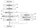
- FIG. 8 is an operation flowchart according to the fourth embodiment.
- step S1 a disconnection judgment (diagnosis) process of the ground wiring 72L is performed (step S1), and it is determined that there is a disconnection failure (step S2).
- step S3 it is determined whether or not the drive unit 1 has been stopped. If the drive unit 1 has not been stopped, the drive unit 1 is stopped (step S6), and the drive unit 1 stop flag is set (step S7). The measurement of the stop time is started (step S8).
- step S3 if the drive unit 1 has been stopped, it is determined whether the specified time has elapsed after the drive unit 1 has stopped (step S4). If the specified time has elapsed, the drive unit 2 is turned off. Stop (step S5).
- the same effects as in the first to third embodiments can be obtained, and the operation of the plurality of linear solenoids 5 can be performed in a predetermined order when the ground wiring 72L is disconnected. Since it is possible to sequentially stop, the occurrence of the disconnection of the ground wiring 72L has an effect that the driving of the linear solenoid 5 in the part with the higher priority of the disconnection order can be stopped early according to the fail-safe operation of the transmission system. .
- An example of an in-vehicle control device to which the present invention is applied is a CVT control device.
- the objects driven by the plurality of linear solenoids 5 are a primary pulley, a secondary pulley, and the like.
- Embodiments 1 to 4 describe the ECU 6 of the vehicle automatic transmission, the present invention is not limited to the vehicle automatic transmission, and the vehicle control device includes a similar circuit configuration for driving an electromagnetic induction load. Even when applied to (for example, an engine control device), the same effect as the present invention can be obtained.
Landscapes
- Engineering & Computer Science (AREA)
- Physics & Mathematics (AREA)
- General Physics & Mathematics (AREA)
- Mechanical Engineering (AREA)
- Chemical & Material Sciences (AREA)
- Combustion & Propulsion (AREA)
- Power Engineering (AREA)
- Testing Of Short-Circuits, Discontinuities, Leakage, Or Incorrect Line Connections (AREA)
Abstract
単一のグランド端子を有する車載制御装置であって、一時的な電圧異常や電流異常による誤検知を回避し、グランド配線の断線故障を正確に検知可能な車載制御装置を実現する。 平滑用電解コンデンサ64のプラス側電極の電圧をモニタするとともに、シャント抵抗69に流れる電流をモニタする。モニタした電流値に基づいて、グランド配線72Lが断線した場合の平滑用電解コンデンサ64のプラス側電極の電圧範囲(電圧閾値)を算出する。算出した電圧閾値と、モニタした上記プラス側電圧とを比較して、グランド配線72Lが断線したか否かを判断するように構成される。
Description
本発明は、車両に搭載される車載制御装置に関する。
車両に搭載される車載制御装置の一例として、車載電気負荷の一部であるリニアソレノイドの制御装置が知られている。
上記リニアソレノイドの制御装置にあっては、グランド端子のオープン故障による誤動作頻度を低下させるため、グランド端子を複数としていた。
しかし、単一グランド端子と比較して、複数のグランド端子を備える場合、各グランド端子と他信号端子との間で複数の短絡故障が発生する場合が考えられ、また、複数のグランドにハーネス電線を接続するためによりコストがかかる課題があり、グランド端子を単一とし、単一のグランド端子のオープン故障(グランド配線の断線)を検知し、適切に対処する技術が公知となっている。
単一のグランド端子のオープン故障を発生すると、昇圧回路が形成され、内部電圧が異常な電圧まで昇圧される可能性があるため、適切な処理を行う必要があるからである。
単一のグランド端子のオープン故障を検知する技術として、特許文献1に記載されたものがある。
特許文献1に記載の技術は、グランド配線の断線異常が発生すると、複数の誘導負荷のいずれかに流れていた励磁電流は、直流電源、電源コンデンサ、及び転流ダイオードを介して還流減衰し、電源コンデンサは還流電流によって充電され、電源コンデンサが充電され、電源コンデンサの監視電圧が上昇することから、この監視電圧が所定の閾値電圧を超過したときに、断線異常が発生したと判断し、適切な処理を行う技術である。
しかしながら、上記特許文献1に記載された技術にあっては、電源コンデンサの監視電圧が、所定の閾値電圧を超過したときに、断線異常が発生したと判断しているが、サージ電圧等の一時的な電圧異常により、所定の閾値電圧を超過する場合が考えられる。このため、グランド配線の断線が発生していない場合であっても、断線発生と誤検知する可能性があった。
本発明の目的は、単一のグランド端子を有する車載制御装置であって、一時的な電圧異常や電流異常による誤検知を回避し、グランド配線の断線故障を正確に検知可能な車載制御装置を実現することである。
上記目的を達成するため、本発明は次のように構成される。
車載制御装置において、
バッテリのマイナス端子に接続されるグランド端子と、
上記バッテリからプラス電圧が供給され、ソレノイドへの通電電流を制御するスイッチ素子と、
アノードがグランドに接続され、カソードが上記スイッチ素子に接続されるダイオードと、
上記ソレノイドの通電電流をモニタする電流モニタ部と、
上記バッテリからプラス電圧が供給され、上記スイッチ素子とグランドとの間に接続されるコンデンサと、
上記コンデンサのプラス側電圧を測定する電圧モニタ部と、
上記電流モニタ部によって測定された電流と、上記電圧モニタ部によって測定された電圧との相関関係に基づいて、上記バッテリのマイナス端子に接続される上記グランド端子がオープン故障しているか否かを判断する断線検出部と、を備える。
本発明によれば、単一のグランド端子を有する車載制御装置であって、一時的な電圧異常や電流異常による誤検知を回避し、グランド配線の断線故障を正確に検知可能な車載制御装置を実現することができる。
以下、本発明を実施するための形態について、図面を参照しながら詳細に説明する。
(実施例1)
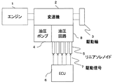
図1は、本発明が適用される車両用のトランスミッションシステムの概略構成図である。
図1は、本発明が適用される車両用のトランスミッションシステムの概略構成図である。
図1において、エンジン1は、変速機2を介して駆動輪3を駆動する。変速機2は、油圧ポンプ4から油圧が供給される油圧回路8によって動作制御される。
また、油圧回路8は、複数のリニアソレノイド5により駆動制御される。これらのリニアソレノイド5は、ECU(Electronic Contorol Unit(制御装置))6から供給される駆動信号7により駆動制御される。
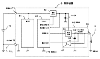
図2は、図1に示したECU(制御装置)6の内部構成図である。
図2において、制御装置6は、電源IC61と、マイコン62と、電源リレー63と、平滑用電解コンデンサ64と、駆動回路(スイッチ素子)66と、差動増幅器67と、回生電流用ダイオード68と、シャント抵抗69と、電源端子71と、グランド端子72と、出力端子70とを備えている。
制御装置6の外部に配置されたバッテリ73の負極(マイナス端子)は、グランドに接続され、バッテリ73の正極(プラス端子)は、制御装置6の電源端子71に接続されている。そして、電源端子71は、電源リレー63を介して平滑用電解コンデンサ64の一方端に接続されるとともに、駆動回路66に接続される。平滑用電解コンデンサ64の他方端は、回路グランドに接続されている。よって、平滑用電解コンデンサ64は、駆動回路(スイッチ素子)66と回路グランド74との間に接続されている。
電源IC61は、電源端子71を介してバッテリ73から電圧が供給される。
駆動回路66は、バッテリ73からプラス電圧が供給され、回生電流用ダイオード68のカソード及びシャント抵抗69を介して出力端子(負荷端子)70に接続されている。
回生電流用ダイオード68のアノードはグランドに接続されている。また、出力端子70は、リニアソレノイド5の一方端に接続されている。リニアソレノイド5の他方端は、車両のグランドに接続されている。
また、シャント抵抗69の駆動回路66側の一方端は、差動増幅器67のプラス側入力端に接続され、シャント抵抗69の出力端子70側の他方端は、差動増幅器67のマイナス側入力端に接続される。差動増幅器67の出力端は、マイコン62の電流モニタ端子に接続される。
マイコン62は、通電遮断信号を電源リレー63に供給し、電源リレー63の通電遮断を制御している。また、マイコン62は、駆動回路66にオンオフ信号を供給し、駆動回路66がリニアソレノイド5の通電電流を制御して駆動している。マイコン62からのオンオフ信号の供給が停止されることにより、駆動回路66によるリニアソレノイド5の駆動が停止される。
また、マイコン62は、平滑用電解コンデンサ64の一方端、つまり、平滑用電解コンデンサ64の電源リレー63に接続された側の端子の電圧(プラス側電圧)をモニタしている。つまり、マイコン62は回路グランド74に接続されており、平滑用電解コンデンサ64の両端電圧をモニタしている。
また、バッテリ73の負極は、グランド線72L及びグランド端子72を介して制御装置6の内部の回路グランド74に接続されている。
駆動部65は、駆動回路66と、差動増幅器67と、回生電流用ダイオード68と、シャント抵抗69とを備えている。
なお、図2には、一つの駆動部65と、この駆動部65により駆動される一つのリニアソレノイド5を示したが、図1に示したように、リニアソレノイド5は複数存在し、それぞれを駆動する駆動部65も複数存在する。図示の簡略化のため、図2には、一つの駆動部65と、この駆動部65により駆動される一つのリニアソレノイド5とを代表として示す。
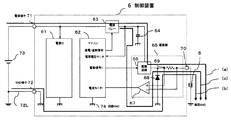
ここで、制御装置6のグランド端子72が接続されている状態と断線している状態における制御装置6の内部の駆動部65に流れる電流について、図2-1を用いて説明する。
制御装置6のグランド端子72が接続されている場合、上述したようにマイコン62は駆動回路66にオンオフ信号を供給し、オン信号が出力されている間は、図2-1の(a)の経路でリニアソレノイド5へ電流が流れる。オン信号が出力された後、オフ信号が出力された場合、図2-1の(b)の経路でリニアソレノイド5へ電流が流れる。このとき、平滑用電解コンデンサ64の両端電圧は、バッテリ73の電圧相当になる。
制御装置6のグランド端子72が接続されている場合、上述したようにマイコン62は駆動回路66にオンオフ信号を供給し、オン信号が出力されている間は、図2-1の(a)の経路でリニアソレノイド5へ電流が流れる。オン信号が出力された後、オフ信号が出力された場合、図2-1の(b)の経路でリニアソレノイド5へ電流が流れる。このとき、平滑用電解コンデンサ64の両端電圧は、バッテリ73の電圧相当になる。
制御装置6のグランド端子72が断線している場合、平滑用電解コンデンサ64と、駆動回路66と、回生電流用ダイオード68と、リニアソレノイド5によって昇圧回路構成されている。マイコン62のオン信号が出力されている場合、図Xの(a)と同一の経路で電流が流れる。一方で、オン信号が出力された後、オフ信号が出力された場合、図2-1の(c)の経路でリニアソレノイド5へ電流が流れる。このとき、経路(c)の電流によって、平滑用電解コンデンサ64の両端電圧が上昇する。つまり、リニアソレノイド5に流れる電流に依存して、平滑用電解コンデンサ64の両端電圧が上昇する。
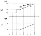
図3は、グランド端子72に接続されたグランド配線72Lが断線していない状態から、断線した状態(オープン故障)となった場合における、マイコン62が検出したシャント抵抗69に流れる電流変化(図3の(b))と、平滑用電解コンデンサ64の両端の電圧変化(図3の(a))との相関関係を示すグラフである。ここでは、トランスミッションシステムの動作状態にもとづき、制御装置6がリニアソレノイド5を制御するために電流制御を行っている。
図3において、時点t0からt2となるまでは、グランド配線72Lは断線しておらず、電圧はV0で略一定であり、電流はI0で略一定である。
時点t2において、グランド配線72Lが断線した場合は、電圧はV0からV0より大の電圧V1に瞬時に上昇する。トランスミッションの制御状態にもとづき、電流を時点t2の後の時点t3から傾斜的に増加させると、時点t7にて電流値I1となる。電圧も電流と同様に、時点t2に後の時点t3において傾斜的に増加し、時点t7にて電圧値V2となる。
つまり、平滑用電解コンデンサ64のプラス側電圧値と、シャント抵抗69に流れる電流値との関係は、グランド配線72Lが断線していない状態と、断線した状態とで異なっている。
したがって、グランド配線72Lが断線した状態における平滑用電解コンデンサ64のプラス側電圧値と、シャント抵抗69に流れる電流値との相関関係を予め実験等により求め、電流を変数とする電圧算出式や電流値と電圧値との対応表等を作成しておけば、モニタした(検出した)電流値から算出した(取得した))電圧値が、モニタされた実際の電圧値と、ほぼ等しければ、グランド配線72Lの断線が発生したと判断することができる。
上述したように、モニタした電流から取得する電圧値は、実際の使用状況等により実験等により求めた電圧値より変動する可能性があることと、サージ電圧やサージ電流が発生する可能性もあるので、図3の(a)に示すように、上限値と下限値とから規定される電圧範囲閾値を使用し、複数回判定を行うこととする。図3の(a)に示した例では、上下限値からなる電圧範囲閾値からなる閾値1、閾値2、及び閾値3により判定し、これらの結果により総合判定する。判定回数は、3回に限らず、2回、又は4回以上と設定することも可能である。
断線判定は、一定時間間隔で行い、時点t4でモニタした電圧値が閾値1の範囲内となった場合、さらに、時点t5でモニタした電圧値が閾値2の範囲内となり、時点t6でモニタした電圧値が閾値3の範囲内となった場合に、グランド配線72Lが断線(クランド端子72のオープン故障)したと判定する。
電圧範囲閾値の上限値及び下限値は、使用する装置の特性、使用環境等を考慮して設定可能である。
図4は、図2に示したマイコン62の断線検出に関する機能ブロック図である。
図4において、マイコン62の断線検出に関する機能ブロックは、電源電圧モニタ部622と、電流モニタ部623と、断線検出部621とを備えている。
断線検出部621は、電圧閾値算出部624と、比較部625と、断線判断部626とを有している。
電源電圧モニタ部622は、平滑用電解コンデンサ64の上記プラス側電圧をモニタ(測定)し、モニタした電圧値を比較部625に出力する。また、電流モニタ部623は、図2に示した差動増幅器67から出力された信号に基づいてシャント抵抗69に流れる電流、つまり、リニアソレノイド5に流れる電流をモニタ(測定)し、モニタした電流値を電圧閾値算出部624に出力する。
電圧閾値算出部624は、電流モニタ部623からの電流値に基づいて、予め定められた算出式等により電圧閾値(電圧範囲)を算出し、比較部625に出力する。
比較部625は、電源電圧モニタ部622から出力された電圧値と、電圧閾値算出部624から出力された電圧閾値(電圧範囲)の上下限値とを比較し、モニタされた電圧値が電圧閾値内に入っているか否かを判断する。電圧値が電圧閾値内に入っている場合は、それを示す信号を断線判断部626に出力する。
断線判断部626は、比較部625からの出力信号に基づいて、上述した判定方法によりグランド配線72Lが断線したか否かを判定する。
断線判断部626が、グランド配線72Lは断線したと判断した場合は、マイコン62から駆動回路66に供給される駆動信号をオフとし、駆動部65のリニアソレノイド5の駆動を停止する。
以上のように、本発明の実施例1によれば、平滑用電解コンデンサ64のプラス側電極の電圧をモニタするとともに、シャント抵抗69に流れる電流をモニタして、モニタした電流値に基づいて、グランド配線72Lが断線した場合の平滑用電解コンデンサ64のプラス側電極の電圧範囲(電圧閾値)を算出して、算出した電圧閾値と、モニタした上記プラス側電圧とを比較して、グランド配線72Lが断線したか否かを判断するように構成される。
したがって、サージ電圧やサージ電流のように一時的な異常電圧、異常電流により、グランド配線72Lの断線が発生したと誤判断することを回避でき、グランド配線72Lの断線故障を正確に検知可能な車載制御装置を実現することができるという効果が得られる。
(実施例2)
次に、本発明の実施例2について説明する。
次に、本発明の実施例2について説明する。
実施例1においては、図3に示したように、シャント抵抗69に流れる電流をモニタして、モニタした電流値に基づいて、グランド配線72Lが断線した場合の平滑用電解コンデンサ64のプラス側電極の電圧範囲(電圧閾値)を算出する構成とした。
これに対して、実施例2は、平滑用電解コンデンサ64のプラス側電極の電圧をモニタして、モニタした電圧値に基づいて、グランド配線72Lが断線した場合のシャント抵抗69に流れる電流範囲(電流閾値)を算出し、算出した電流閾値と、モニタしたシャント抵抗69に流れる電流とを比較して、グランド配線72Lが断線したか否かを判断するように構成する例である。
実施例2による制御装置の概略構成図は、図2に示した例と同様であるので、図示及びその詳細な説明は省略する。
実施例2においては、図3の(b)に示した電流波形で、時点t4でモニタした電流値が第1の電流閾値の範囲内となった場合、さらに、時点t5でモニタした電流値が第2電流閾値の範囲内となり、時点t6でモニタした電流値が第3電流閾値の範囲内となった場合に、グランド配線72Lが断線したと判定する。
図5は、図2に示したマイコン62の断線検出に関する機能ブロック図である。
図5に示した例と、図4に示した例との相違点は、図4における電圧閾値算出部624が削除され、電流モニタ623からの出力値(電流値)が比較部625に出力される。
また、電源電圧モニタ622と比較部625との間に、電流閾値算出部627が配置されている。この電流閾値算出部627がモニタした電圧値に基づいて、グランド配線72Lが断線した場合のシャント抵抗69に流れる電流範囲(電流閾値)を算出し、比較部625に出力する。
比較部625は、電流モニタ部623から出力された電流値と、電流閾値算出部627から出力された電圧閾値(電圧範囲)の上下限値とを比較し、モニタされた電流値が電流閾値内に入っているか否かを判断する。電流値が電流閾値内に入っている場合は、それを示す信号を断線判断部626に出力する。
断線判断部626は、比較部625からの出力信号に基づいて、上述した判定方法によりグランド配線72Lが断線したか否かを判定する。
断線判断部626が、グランド配線72Lは断線したと判断した場合は、マイコン62から駆動回路66に供給される駆動信号をオフとし、駆動部65のリニアソレノイド5の駆動を停止する。
本発明の実施例2においても、実施例1と同様な効果を得ることができる。
(実施例3)
次に、本発明の実施例3について説明する。
次に、本発明の実施例3について説明する。
実施例3は、実施例1及び2と同様に、グランド配線72Lが断線したことを平滑用電解コンデンサ64のプラス側電極の電圧と、シャント抵抗69に流れる電流(リニアソレノイド5に流れる電流))との相関関係に基づいて判断する。
実施例3においては、グランド配線72Lが断線した状態で、駆動部65の駆動回路66に駆動信号であるオンオフ信号を供給した場合、平滑用電解コンデンサ64のプラス側電極の電圧波形と、シャント抵抗69に流れる電流波形とに相違が生じることに着目し、グランド配線72Lが断線したことを判断する。
図6は、実施例3における、図2に示したマイコン62の断線検出に関する機能ブロック図であり、図7は、実施例3におけるグランド配線72L断線検出の原理説明図である。
図7において、図7の(a)は、駆動回路66に供給される駆動信号(オンオフ制御信号)の波形であり、図7の(b)は、グランド配線72Lが断線した場合のシャント抵抗69に流れる電流の波形である。
また、図7の(c)は、グランド配線72Lが断線した場合の平滑用電解コンデンサ64のプラス側電極の電圧波形(上流側電圧波形)であり、図7の(d)は、グランド配線72Lが断線していいない場合のシャント抵抗69に流れる電流の波形であり、図7の(e)は、グランド配線72Lが断線していない場合の平滑用電解コンデンサ64のプラス側電極の電圧波形である。
図7の(e)に示すように、グランド配線72Lが断線していない場合の平滑用電解コンデンサ64のプラス側電極の電圧は、オンオフ制御信号のオン状態及びオフ状態に関係なく、脈動はあるが、ほぼ一定電圧を維持している。
一方、図7の(d)に示すように、グランド配線72Lが断線した場合の平滑用電解コンデンサ64のプラス側電極の電圧は、鋸歯状波形となり、オンオフ制御信号のオフ信号出力期間中、一旦電圧が持ち上がり、オンオフ制御信号の立ち上り時に向かって減少する波形となる。
また、図7の(b)に示すように、グランド配線72Lが断線した場合のシャント抵抗69に流れる電流は、鋸歯状波形となり、オンオフ制御信号の立ち上り時から、立ち下り時に向かって増加し、立ち下り時からオンオフ制御信号のオフ信号出力期間中に一旦ゼロまで低下する波形となる。
この電流がオンオフ信号の立ち下り時から、次の立ち上り時に向かって減少する状態が回生電流の発生時であり、この回生電流の発生時には、上記プラス側電極の電圧は、電流波形とは逆に、オンオフ制御信号の立ち下がり時から、立ち上がりに向かって増加する。
したがって、シャント抵抗69に流れる電流の波形と、平滑用電解コンデンサ64のプラス側電極の電圧波形とを比較することによって、グランド配線72Lが断線したか否かを判断することができる。
ただし、電流や電圧の脈動、サージ電圧及びサージ電流の影響による誤判断を回避するため、グランド配線72Lが断線した場合における電流波形と電圧波形との関係が、上述したグランド配線72Lが断線したと判断可能な状態となることが、複数回連続して発生した場合(例えば、連続して3回)に、断線発生と判断することとする。
また、図6において、実施例3における断線検出部621は、回生電流依存判断部628と、断線判断部626とを備える。電源電圧モニタ部622から出力された電圧と、電流モニタ部623から出力された電流とが回生電流依存判断部628に出力され、回生電流依存判断部628が、供給された電流波形と電圧波形とを比較し、グランド配線72Lが断線した場合の関係(予め定めた依存関係)となっているか否かの依存関係を判断する。グランド配線72Lが断線した場合の依存関係となっている場合には、それを示す信号を断線判断部626に出力する。
断線判断部626は、回生電流依存判断部628から、断線が発生したこと示す信号が複数回連続して出力された場合に、グランド配線72Lが断線したと判断し、マイコン62から駆動回路66に供給される駆動信号をオフとし、駆動部65のリニアソレノイド5の駆動を停止する。
本発明の実施例3おいても、実施例1と同様な効果を得ることができる。
(実施例4)
次に、本発明の実施例4について説明する。
次に、本発明の実施例4について説明する。
上述したように、リニアソレノイド5は複数のソレノイドからなり、それぞれを駆動する駆動部65も複数存在する。このため、実施例1~3において、断線検出部621が、グランド配線72Lの断線は発生したと判断した場合、複数の駆動部65に、それぞれのリニアソレノイド5の駆動(リニアソレノイド5への通電)を一斉に停止させるように指示することも可能であるし、予め定めた優先順位により、順次停止させるように指示することも可能である。
本発明の実施例4は、複数のリニアソレノイド5の駆動を予め定めた優先順位により、順次停止させるように指示する例であり、各実施例における断線判断部626が実行する。
図8は、実施例4における動作フローチャートである。
なお、図8に示した例においては、駆動部が駆動部1と駆動部2との2つ存在する場合を例としている。駆動部が3つ以上存在する場合も、同様な処理が可能である。
図8において、グランド配線72Lの断線判断(診断)処理を行い(ステップS1)、断線故障であることを確定する(ステップS2)。
次に、駆動部1が停止済みか否かを判断し(ステップS3)、停止済みでなければ、駆動部1を停止させ(ステップS6)、駆動部1停止フラグをセットし(ステップS7)、停止時間の計測を開始する(ステップS8)。
ステプS3において、駆動部1が停止済みであれば、駆動部1が停止後、規定時間を経過したか否かを判断し(ステップS4)、規定時間が経過していれば、駆動部2を停止する(ステップS5)。
以上のように、本発明の実施例4によれば、実施例1~3と同様な効果が得られる他、グランド配線72Lの断線発生時に、複数のリニアソレノイド5の動作を、所定の順序で順次停止することができるので、グランド配線72Lの断線発生により、トランスミッションシステムのフェールセーフ動作に従い、遮断順序の優先順位が高い部分のリニアソレノイド5の駆動を早期に停止することができるという効果を有する。
なお、本発明が適用される車載制御装置の一例としては、CVTの制御装置がある。この場合、複数のリニアソレノイド5が駆動する対象は、プライマリプーリ、セカンダリプーリ等である。
実施形態1から4は、車両用自動変速機のECU6について記載しているが、本発明は車両用自動変速機に限定されず、電磁誘導負荷を駆動する同様の回路構成を備える車両用制御装置(例えば、エンジン制御装置)に対して適用した場合であっても、本発明と同様の効果を得ることができる
1・・・エンジン、2・・・変速機、3・・・駆動輪、4・・・油圧ポンプ、5・・・リニアソレノイド、6・・・ECU(制御装置)、61・・・電源IC、62・・・マイコン、63・・・リレー、64・・・平滑用電解コンデンサ、65・・・駆動部、66・・・駆動回路(スイッチ素子)、67・・・差動増幅器、68・・・回生電流用ダイオード、69・・・シャント抵抗、70・・・出力端子、71・・・電源端子、72・・・グランド端子、72L・・・グランド配線、73・・・バッテリ、621・・・断線検出部、622・・・電源電圧モニタ部、623・・・電流モニタ部、624・・・電圧閾値算出部、625・・・比較部、626・・・断線判断部、627・・・電流閾値算出部、628・・・回生電流依存判断部
Claims (9)
- バッテリのマイナス端子に接続されるグランド端子と、
上記バッテリからプラス電圧が供給され、ソレノイドへの通電電流を制御するスイッチ素子と、
アノードがグランドに接続され、カソードが上記スイッチ素子に接続されるダイオードと、
上記ソレノイドの通電電流を測定する電流モニタ部と、
上記バッテリからプラス電圧が供給され、上記スイッチ素子とグランドとの間に接続されるコンデンサと、
上記コンデンサのプラス側電圧を測定する電圧モニタ部と、
上記電流モニタ部によって測定された通電電流と、上記電圧モニタ部によって測定された電圧との相関関係に基づいて、上記バッテリのマイナス端子に接続される上記グランド端子がオープン故障しているか否かを判断する断線検出部と、
を備えることを特徴とする車載制御装置。 - 請求項1に記載の車載制御装置において、
上記断線検出部は、
上記電流モニタ部によって測定された電流に基づいて、上記グランド端子がオープン故障している場合の上記コンデンサのプラス側電圧の電圧範囲を算出し、電圧閾値とする電圧閾値算出部と、
上記電圧モニタ部により測定された上記プラス側電圧が、上記電圧閾値算出部により算出された上記電圧閾値内に入っているか否かにより、上記グランド端子がオープン故障しているか否かを判断する断線判断部と、を有することを特徴とする車載制御装置。 - 請求項1に記載の車載制御装置において、
上記断線検出部は、
上記電圧モニタ部によって測定された電圧に基づいて、上記グランド端子がオープン故障している場合の上記ソレノイドの通電電流範囲を算出し、電流閾値とする電流閾値算出部と、
上記電流モニタ部により測定された上記通電電流が、上記電流閾値算出部により算出された上記電流閾値内に入っているか否かにより、上記グランド端子がオープン故障しているか否かを判断する断線判断部と、を有することを特徴とする車載制御装置。 - 請求項1に記載の車載制御装置において、
上記断線検出部は、
上記電圧モニタ部によって測定された上記電圧の波形と、上記電流モニタ部により測定された上記通電電流の波形との相関関係に基づいて、上記グランド端子がオープン故障している場合に発生する上記電圧の波形と上記通電電流の波形とが予め定めた依存関係を有するか否かを判断する回生電流依存判断部と、
上記回生電流依存判断部により判断された上記電圧の波形と上記通電電流の波形とが予め定めた依存関係を有するか否かの判断に基づいて、上記グランド端子がオープン故障しているか否かを判断する断線判断部と、を有することを特徴とする車載制御装置。 - 請求項2に記載の車載制御装置において、
上記断線判断部は、上記プラス側電圧が、上記電圧閾値算出部により算出された上記電圧閾値内に入っていることを、複数回判断したときに上記グランド端子がオープン故障していると判断することを特徴とする車載制御装置。 - 請求項3に記載の車載制御装置において、
上記断線判断部は、上記測定された上記通電電流が、上記電流閾値算出部により算出された上記電流閾値内に入っていることを、複数回判断したときに上記グランド端子がオープン故障していると判断することを特徴とする車載制御装置。 - 請求項4に記載の車載制御装置において、
上記断線判断部は、上記電圧の波形と上記通電電流の波形とが予め定めた依存関係を有することを、複数回判断したときに上記グランド端子がオープン故障していると判断することを特徴とする車載制御装置。 - 請求項1から7のうちのいずれか一項に記載の車載制御装置において、
上記ソレノイドは複数のソレノイドからなり、上記断線判断部は、上記グランド端子がオープン故障しているか否かを判断したとき、上記複数のソレノイドへの通電を予め定めた優先順位により順次停止させることを特徴とする車載制御装置。 - 請求項1から7のうちのいずれか一項に記載の車載制御装置において、
上記ソレノイドは複数のソレノイドからなり、上記断線判断部は、上記グランド端子がオープン故障しているか否かを判断したとき、上記複数のソレノイドへの通電を一斉に停止させることを特徴とする車載制御装置。
Priority Applications (4)
| Application Number | Priority Date | Filing Date | Title |
|---|---|---|---|
| JP2018556243A JP6649509B2 (ja) | 2016-12-16 | 2017-11-02 | 車載制御装置 |
| US16/342,258 US10976375B2 (en) | 2016-12-16 | 2017-11-02 | On-board controller |
| CN201780077579.3A CN110072737B (zh) | 2016-12-16 | 2017-11-02 | 车载控制装置 |
| DE112017005122.3T DE112017005122T5 (de) | 2016-12-16 | 2017-11-02 | Fahrzeugseitige Steuerung |
Applications Claiming Priority (2)
| Application Number | Priority Date | Filing Date | Title |
|---|---|---|---|
| JP2016244641 | 2016-12-16 | ||
| JP2016-244641 | 2016-12-16 |
Publications (1)
| Publication Number | Publication Date |
|---|---|
| WO2018110134A1 true WO2018110134A1 (ja) | 2018-06-21 |
Family
ID=62559810
Family Applications (1)
| Application Number | Title | Priority Date | Filing Date |
|---|---|---|---|
| PCT/JP2017/039686 Ceased WO2018110134A1 (ja) | 2016-12-16 | 2017-11-02 | 車載制御装置 |
Country Status (5)
| Country | Link |
|---|---|
| US (1) | US10976375B2 (ja) |
| JP (1) | JP6649509B2 (ja) |
| CN (1) | CN110072737B (ja) |
| DE (1) | DE112017005122T5 (ja) |
| WO (1) | WO2018110134A1 (ja) |
Cited By (6)
| Publication number | Priority date | Publication date | Assignee | Title |
|---|---|---|---|---|
| CN110658481A (zh) * | 2018-06-28 | 2020-01-07 | 李尔公司 | 接地丢失检测系统 |
| JP2020012781A (ja) * | 2018-07-20 | 2020-01-23 | パイオニア株式会社 | 検査装置 |
| WO2020145029A1 (ja) * | 2019-01-09 | 2020-07-16 | 株式会社デンソー | 通電制御装置 |
| JPWO2022038791A1 (ja) * | 2020-08-21 | 2022-02-24 | ||
| JP2022131975A (ja) * | 2021-02-26 | 2022-09-07 | 工機ホールディングス株式会社 | 電気機器 |
| WO2022254780A1 (ja) * | 2021-05-31 | 2022-12-08 | 日立Astemo株式会社 | 車載用制御装置 |
Families Citing this family (3)
| Publication number | Priority date | Publication date | Assignee | Title |
|---|---|---|---|---|
| US11131720B2 (en) * | 2017-05-11 | 2021-09-28 | Mitsubishi Electric Corporation | Electronic control device |
| CN113777512B (zh) * | 2020-06-09 | 2025-02-25 | 三星Sdi株式会社 | 电流测量装置、包含其的电池系统及其方法、电动车辆 |
| PL3923008T3 (pl) * | 2020-06-09 | 2024-01-03 | Samsung Sdi Co., Ltd. | Sposób i urządzenie do pomiaru prądu elektrycznego układu baterii |
Citations (4)
| Publication number | Priority date | Publication date | Assignee | Title |
|---|---|---|---|---|
| WO2014017234A1 (ja) * | 2012-07-23 | 2014-01-30 | 日立オートモティブシステムズ株式会社 | 電子制御装置 |
| JP2015077818A (ja) * | 2013-10-15 | 2015-04-23 | 三菱電機株式会社 | 誘導性負荷の給電制御装置 |
| JP2016141351A (ja) * | 2015-02-04 | 2016-08-08 | ボッシュ株式会社 | 電子制御装置のグランド断線検出方法及び電子制御装置 |
| WO2017057682A1 (ja) * | 2015-09-30 | 2017-04-06 | アイシン・エィ・ダブリュ株式会社 | 駆動装置 |
Family Cites Families (13)
| Publication number | Priority date | Publication date | Assignee | Title |
|---|---|---|---|---|
| JP2001037069A (ja) * | 1999-07-15 | 2001-02-09 | Anden | 断線検出機能を有する負荷駆動装置 |
| JP4364554B2 (ja) * | 2002-06-07 | 2009-11-18 | 株式会社ルネサステクノロジ | スイッチング電源装置及びスイッチング電源システム |
| JP4050292B2 (ja) * | 2005-09-09 | 2008-02-20 | 三菱電機株式会社 | 電子制御装置 |
| JP4741391B2 (ja) * | 2006-03-09 | 2011-08-03 | オムロンオートモーティブエレクトロニクス株式会社 | モータ駆動回路の地絡検出装置 |
| JP5401250B2 (ja) * | 2009-10-06 | 2014-01-29 | 日立オートモティブシステムズ株式会社 | 地絡検出装置 |
| CN201523211U (zh) * | 2009-10-13 | 2010-07-07 | 奇瑞汽车股份有限公司 | 一种电动汽车整车控制器的电源电路 |
| CN103282786A (zh) * | 2011-12-27 | 2013-09-04 | 株式会社日立制作所 | 电池系统和接地检测装置 |
| JP6028379B2 (ja) * | 2012-03-06 | 2016-11-16 | 株式会社ジェイテクト | ソレノイド制御装置 |
| AU2013245827B2 (en) * | 2012-04-12 | 2016-11-10 | Littelfuse, Inc. | Neutral grounding resistor monitor |
| JP6051909B2 (ja) * | 2013-02-12 | 2016-12-27 | 株式会社デンソー | 電力供給装置 |
| US9543834B2 (en) * | 2013-04-26 | 2017-01-10 | Fujitsu Ten Limited | Switching regulator, electronic device, and electronic circuit |
| CN105939896B (zh) * | 2014-02-06 | 2018-12-11 | 日立汽车系统株式会社 | 负载驱动电路 |
| JP2015208143A (ja) * | 2014-04-22 | 2015-11-19 | 日立オートモティブシステムズ株式会社 | 電動機駆動装置 |
-
2017
- 2017-11-02 US US16/342,258 patent/US10976375B2/en active Active
- 2017-11-02 JP JP2018556243A patent/JP6649509B2/ja active Active
- 2017-11-02 WO PCT/JP2017/039686 patent/WO2018110134A1/ja not_active Ceased
- 2017-11-02 DE DE112017005122.3T patent/DE112017005122T5/de active Pending
- 2017-11-02 CN CN201780077579.3A patent/CN110072737B/zh active Active
Patent Citations (4)
| Publication number | Priority date | Publication date | Assignee | Title |
|---|---|---|---|---|
| WO2014017234A1 (ja) * | 2012-07-23 | 2014-01-30 | 日立オートモティブシステムズ株式会社 | 電子制御装置 |
| JP2015077818A (ja) * | 2013-10-15 | 2015-04-23 | 三菱電機株式会社 | 誘導性負荷の給電制御装置 |
| JP2016141351A (ja) * | 2015-02-04 | 2016-08-08 | ボッシュ株式会社 | 電子制御装置のグランド断線検出方法及び電子制御装置 |
| WO2017057682A1 (ja) * | 2015-09-30 | 2017-04-06 | アイシン・エィ・ダブリュ株式会社 | 駆動装置 |
Cited By (14)
| Publication number | Priority date | Publication date | Assignee | Title |
|---|---|---|---|---|
| CN110658481B (zh) * | 2018-06-28 | 2022-01-07 | 李尔公司 | 接地丢失检测系统 |
| CN110658481A (zh) * | 2018-06-28 | 2020-01-07 | 李尔公司 | 接地丢失检测系统 |
| JP2020012781A (ja) * | 2018-07-20 | 2020-01-23 | パイオニア株式会社 | 検査装置 |
| WO2020145029A1 (ja) * | 2019-01-09 | 2020-07-16 | 株式会社デンソー | 通電制御装置 |
| JP7609165B2 (ja) | 2020-08-21 | 2025-01-07 | 日本電信電話株式会社 | 直流配電システム、制御装置、動作状態判定方法、及びプログラム |
| JPWO2022038791A1 (ja) * | 2020-08-21 | 2022-02-24 | ||
| WO2022038791A1 (ja) * | 2020-08-21 | 2022-02-24 | 日本電信電話株式会社 | 直流配電システム、制御装置、動作状態判定方法、及びプログラム |
| JP2022131975A (ja) * | 2021-02-26 | 2022-09-07 | 工機ホールディングス株式会社 | 電気機器 |
| JP7585878B2 (ja) | 2021-02-26 | 2024-11-19 | 工機ホールディングス株式会社 | 電気機器 |
| JPWO2022254780A1 (ja) * | 2021-05-31 | 2022-12-08 | ||
| CN117203092A (zh) * | 2021-05-31 | 2023-12-08 | 日立安斯泰莫株式会社 | 车载用控制装置 |
| WO2022254780A1 (ja) * | 2021-05-31 | 2022-12-08 | 日立Astemo株式会社 | 車載用制御装置 |
| JP7629094B2 (ja) | 2021-05-31 | 2025-02-12 | 日立Astemo株式会社 | 車載用制御装置 |
| US12447914B2 (en) | 2021-05-31 | 2025-10-21 | Hitachi Astemo, Ltd. | Vehicle-mounted control device |
Also Published As
| Publication number | Publication date |
|---|---|
| US20190326742A1 (en) | 2019-10-24 |
| DE112017005122T5 (de) | 2019-06-27 |
| CN110072737A (zh) | 2019-07-30 |
| JP6649509B2 (ja) | 2020-02-19 |
| US10976375B2 (en) | 2021-04-13 |
| CN110072737B (zh) | 2022-06-10 |
| JPWO2018110134A1 (ja) | 2019-07-18 |
Similar Documents
| Publication | Publication Date | Title |
|---|---|---|
| JP6649509B2 (ja) | 車載制御装置 | |
| US8891210B2 (en) | Electronic control unit including discharging circuit with plurality of resistors connected in series | |
| US10640059B2 (en) | Drive device | |
| JP6400610B2 (ja) | 負荷駆動回路 | |
| US11025074B2 (en) | Charging management apparatus | |
| US10386419B2 (en) | Battery management device, battery monitoring circuit, and control system | |
| CN111090027A (zh) | 高压系统和用于监视高压系统中的绝缘故障的方法 | |
| EP3933421B1 (en) | Detection circuit and detection method for electric control device, and electric vehicle | |
| US9964579B2 (en) | Voltage detection apparatus | |
| CN110884558B (zh) | 用于向车辆中的eps供应电力的控制装置和方法 | |
| CN111902308B (zh) | 用于运行机动车的方法和设备 | |
| US9419523B2 (en) | Method for identifying a short-line fault or a line interruption for a switched inductive load | |
| CN113273047B (zh) | 用于致动机电机动车辆转向系统的电动机的具有短路保护的电子控制装置 | |
| WO2020071079A1 (ja) | 高電圧機器の制御装置 | |
| CN113167825A (zh) | 用于在不接地的高压系统中进行故障识别的电路组件 | |
| KR20180042755A (ko) | Pra 고장 진단 장치 | |
| JP2016141351A (ja) | 電子制御装置のグランド断線検出方法及び電子制御装置 | |
| JPWO2018198631A1 (ja) | 電子制御装置 | |
| KR20180061567A (ko) | 모터 고장 진단 장치 및 방법 | |
| CN108292920B (zh) | 电磁负载驱动装置以及车载控制系统 | |
| JP2012244895A (ja) | 電気自動車のコンバータ制御方法及びその装置 | |
| KR100829326B1 (ko) | 전기차 제어 장치 | |
| JP2016225132A (ja) | 電源制御装置 | |
| JP6788489B2 (ja) | 電気回路およびその制御装置 | |
| KR20160039247A (ko) | 전자 정류식 전기 모터에서 결함 결정 방법 |
Legal Events
| Date | Code | Title | Description |
|---|---|---|---|
| 121 | Ep: the epo has been informed by wipo that ep was designated in this application |
Ref document number: 17880609 Country of ref document: EP Kind code of ref document: A1 |
|
| ENP | Entry into the national phase |
Ref document number: 2018556243 Country of ref document: JP Kind code of ref document: A |
|
| 122 | Ep: pct application non-entry in european phase |
Ref document number: 17880609 Country of ref document: EP Kind code of ref document: A1 |