WO2018109839A1 - バルブシート及びバルブ構造 - Google Patents
バルブシート及びバルブ構造 Download PDFInfo
- Publication number
- WO2018109839A1 WO2018109839A1 PCT/JP2016/087053 JP2016087053W WO2018109839A1 WO 2018109839 A1 WO2018109839 A1 WO 2018109839A1 JP 2016087053 W JP2016087053 W JP 2016087053W WO 2018109839 A1 WO2018109839 A1 WO 2018109839A1
- Authority
- WO
- WIPO (PCT)
- Prior art keywords
- shape
- valve
- hole
- valve seat
- seat
- Prior art date
Links
Images


Classifications
-
- F—MECHANICAL ENGINEERING; LIGHTING; HEATING; WEAPONS; BLASTING
- F04—POSITIVE - DISPLACEMENT MACHINES FOR LIQUIDS; PUMPS FOR LIQUIDS OR ELASTIC FLUIDS
- F04B—POSITIVE-DISPLACEMENT MACHINES FOR LIQUIDS; PUMPS
- F04B53/00—Component parts, details or accessories not provided for in, or of interest apart from, groups F04B1/00 - F04B23/00 or F04B39/00 - F04B47/00
- F04B53/06—Venting
-
- F—MECHANICAL ENGINEERING; LIGHTING; HEATING; WEAPONS; BLASTING
- F04—POSITIVE - DISPLACEMENT MACHINES FOR LIQUIDS; PUMPS FOR LIQUIDS OR ELASTIC FLUIDS
- F04B—POSITIVE-DISPLACEMENT MACHINES FOR LIQUIDS; PUMPS
- F04B53/00—Component parts, details or accessories not provided for in, or of interest apart from, groups F04B1/00 - F04B23/00 or F04B39/00 - F04B47/00
- F04B53/10—Valves; Arrangement of valves
- F04B53/1002—Ball valves
- F04B53/1005—Ball valves being formed by two closure members working in series
-
- F—MECHANICAL ENGINEERING; LIGHTING; HEATING; WEAPONS; BLASTING
- F04—POSITIVE - DISPLACEMENT MACHINES FOR LIQUIDS; PUMPS FOR LIQUIDS OR ELASTIC FLUIDS
- F04B—POSITIVE-DISPLACEMENT MACHINES FOR LIQUIDS; PUMPS
- F04B53/00—Component parts, details or accessories not provided for in, or of interest apart from, groups F04B1/00 - F04B23/00 or F04B39/00 - F04B47/00
- F04B53/10—Valves; Arrangement of valves
- F04B53/1087—Valve seats
-
- F—MECHANICAL ENGINEERING; LIGHTING; HEATING; WEAPONS; BLASTING
- F16—ENGINEERING ELEMENTS AND UNITS; GENERAL MEASURES FOR PRODUCING AND MAINTAINING EFFECTIVE FUNCTIONING OF MACHINES OR INSTALLATIONS; THERMAL INSULATION IN GENERAL
- F16K—VALVES; TAPS; COCKS; ACTUATING-FLOATS; DEVICES FOR VENTING OR AERATING
- F16K1/00—Lift valves or globe valves, i.e. cut-off apparatus with closure members having at least a component of their opening and closing motion perpendicular to the closing faces
- F16K1/14—Lift valves or globe valves, i.e. cut-off apparatus with closure members having at least a component of their opening and closing motion perpendicular to the closing faces with ball-shaped valve member
-
- F—MECHANICAL ENGINEERING; LIGHTING; HEATING; WEAPONS; BLASTING
- F16—ENGINEERING ELEMENTS AND UNITS; GENERAL MEASURES FOR PRODUCING AND MAINTAINING EFFECTIVE FUNCTIONING OF MACHINES OR INSTALLATIONS; THERMAL INSULATION IN GENERAL
- F16K—VALVES; TAPS; COCKS; ACTUATING-FLOATS; DEVICES FOR VENTING OR AERATING
- F16K1/00—Lift valves or globe valves, i.e. cut-off apparatus with closure members having at least a component of their opening and closing motion perpendicular to the closing faces
- F16K1/32—Details
- F16K1/34—Cutting-off parts, e.g. valve members, seats
- F16K1/42—Valve seats
-
- F—MECHANICAL ENGINEERING; LIGHTING; HEATING; WEAPONS; BLASTING
- F16—ENGINEERING ELEMENTS AND UNITS; GENERAL MEASURES FOR PRODUCING AND MAINTAINING EFFECTIVE FUNCTIONING OF MACHINES OR INSTALLATIONS; THERMAL INSULATION IN GENERAL
- F16K—VALVES; TAPS; COCKS; ACTUATING-FLOATS; DEVICES FOR VENTING OR AERATING
- F16K31/00—Actuating devices; Operating means; Releasing devices
- F16K31/12—Actuating devices; Operating means; Releasing devices actuated by fluid
-
- F—MECHANICAL ENGINEERING; LIGHTING; HEATING; WEAPONS; BLASTING
- F04—POSITIVE - DISPLACEMENT MACHINES FOR LIQUIDS; PUMPS FOR LIQUIDS OR ELASTIC FLUIDS
- F04B—POSITIVE-DISPLACEMENT MACHINES FOR LIQUIDS; PUMPS
- F04B13/00—Pumps specially modified to deliver fixed or variable measured quantities
-
- F—MECHANICAL ENGINEERING; LIGHTING; HEATING; WEAPONS; BLASTING
- F04—POSITIVE - DISPLACEMENT MACHINES FOR LIQUIDS; PUMPS FOR LIQUIDS OR ELASTIC FLUIDS
- F04B—POSITIVE-DISPLACEMENT MACHINES FOR LIQUIDS; PUMPS
- F04B43/00—Machines, pumps, or pumping installations having flexible working members
- F04B43/02—Machines, pumps, or pumping installations having flexible working members having plate-like flexible members, e.g. diaphragms
-
- Y—GENERAL TAGGING OF NEW TECHNOLOGICAL DEVELOPMENTS; GENERAL TAGGING OF CROSS-SECTIONAL TECHNOLOGIES SPANNING OVER SEVERAL SECTIONS OF THE IPC; TECHNICAL SUBJECTS COVERED BY FORMER USPC CROSS-REFERENCE ART COLLECTIONS [XRACs] AND DIGESTS
- Y10—TECHNICAL SUBJECTS COVERED BY FORMER USPC
- Y10T—TECHNICAL SUBJECTS COVERED BY FORMER US CLASSIFICATION
- Y10T137/00—Fluid handling
- Y10T137/7722—Line condition change responsive valves
- Y10T137/7837—Direct response valves [i.e., check valve type]
- Y10T137/7904—Reciprocating valves
- Y10T137/7908—Weight biased
- Y10T137/7909—Valve body is the weight
- Y10T137/791—Ball valves
Definitions
- the present invention relates to a valve seat and a valve structure.
- a reciprocating pump as a metering pump device that introduces a transfer fluid into a pump chamber via a suction valve by a reciprocating motion of a reciprocating member such as a diaphragm and discharges the transfer fluid from the pump chamber via a discharge valve
- a discharge valve Employs ball valves as suction valves and discharge valves. This ball valve is known to enter a gas-locked state when a gas such as a gas generated from a transfer fluid in the pump chamber or a gas such as air sucked together with the transfer fluid stays in the lower part of the valve.
- a reciprocating pump having an automatic gas venting mechanism has been proposed (see Patent Document 1 below).
- the passage immediately after the discharge valve is branched into a discharge liquid passage that extends horizontally to the discharge port and a gas vent passage that extends immediately above.
- a gas vent valve is arranged in the gas vent passage, and the gas vent valve is constituted by one ball valve and valve seats arranged above and below it.
- This gas vent valve is configured so that the valve ball and the valve seat above it have an incomplete seal with intentionally poor adhesion. For this reason, during the intake stroke, leakage of liquid or gas from the outside is prevented by the valve ball and the lower valve seat in the same manner as a normal ball check valve. On the contrary, during the discharge stroke, the gas slightly mixed in the liquid is efficiently discharged to the outside through an incomplete seal between the valve ball and the upper valve seat.
- the present invention has been made in view of the above circumstances, and an object thereof is to provide a valve seat and a valve structure capable of preventing the occurrence of gas lock while maintaining the sealing performance of the valve ball.
- the valve seat according to the present invention is a valve seat disposed below the valve ball, and is formed of an annular member having a hole portion serving as a flow path through which a transfer fluid flows in the center, and the central axis of the hole portion is Installed in the vertical direction, connected to the upper end of the hole, has a seating surface that fits the outer shape of the valve ball and seats the valve ball, and a lower end surface connected to the lower end of the hole,
- the hole is characterized in that a horizontal distance from the central axis to the inner peripheral surface of the hole is formed in a predetermined shape that is not constant over the entire circumference of the inner peripheral surface of the hole.
- the predetermined shape is such that the difference between the maximum value and the minimum value of the horizontal distance over the entire circumference of the inner peripheral surface of the hole is 10% or more and 30% with respect to the maximum value. % Or less.
- the predetermined shape is a partially deformed circular shape, an elliptical shape, a saddle shape, a drum shape, an eccentric circular shape, an overlapping circular shape, a cross shape, a square shape, and a triangular shape when viewed in a horizontal section. Any one of the shapes.
- a valve structure according to the present invention is a valve structure including a valve ball, a valve seat disposed below the valve ball, and a seat holder that supports the valve seat. It consists of an annular member having a hole serving as a seat flow path through which it is installed so that the center axis of the hole faces in the vertical direction, and is connected to the upper end of the hole to match the outer shape of the valve ball and A seating surface on which the valve ball is seated and a lower end surface connected to the lower end of the hole; the seat holder has a holder channel communicating with the seat channel; and the hole is the central axis The horizontal distance from the inner peripheral surface of the hole to the inner peripheral surface of the hole is formed in a predetermined shape that is not constant over the entire inner peripheral surface of the hole. Projecting toward the central axis And having a plurality of ridges extending along the mandrel.
- the predetermined shape is such that the difference between the maximum value and the minimum value of the horizontal distance over the entire circumference of the inner peripheral surface of the hole is 10% or more and 30% with respect to the maximum value. % Or less.
- the predetermined shape is a partially deformed circular shape, an elliptical shape, a saddle shape, a drum shape, an eccentric circular shape, an overlapping circular shape, a cross shape, a square shape, and a triangular shape when viewed in a horizontal section. Any one of the shapes.
- valve balls are arranged vertically, the valve seat is arranged below each valve ball, and the seat holder supports the lower end surface of the lower valve seat.
- FIG. 4 is a cross-sectional view taken along line A-A ′ of FIG. 3.
- FIG. 4 is a sectional view taken along line B-B ′ in FIG. 3.
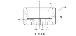
- FIG. 7 is a sectional view taken along line C-C ′ of FIG. 6.
- It is a top view which shows the modification of the valve seat. It is a top view which shows the modification of the valve seat.
- valve structure according to the present invention is configured as a metering pump by applying the valve structure according to the present invention to a suction valve and a discharge valve, and the valve seat according to the present invention is used as its constituent member.
- the present invention is not limited to the pump device.
- FIG. 1 is a cross-sectional view showing a main part of a reciprocating pump to which a valve seat 50 and a valve structure according to an embodiment of the present invention are applied.
- 2 is a perspective view showing a valve seat 50 of the reciprocating pump
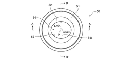
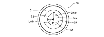
- FIG. 3 is a plan view showing the valve seat 50.
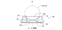
- FIG. 4 is a cross-sectional view taken along the line A-A ′ of FIG. 3
- FIG. 5 is a cross-sectional view taken along the line B-B ′ of FIG. 3.
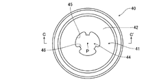
- FIG. 6 is a plan view showing the seat holder 40 of the reciprocating pump
- FIG. 7 is a cross-sectional view taken along line C-C ′ of FIG.
- a metering pump 1 having a valve seat 50 and a valve structure according to an embodiment of the present invention has, for example, a rod-shaped drive shaft 2.
- the drive shaft 2 is reciprocated in the direction indicated by the arrow in the figure by a motor driving force or electromagnetic force of a pump main body (not shown).
- a flexible diaphragm 4 is attached to the tip of the drive shaft 2 via an insert bolt 3.
- the diaphragm 4 forms a pump chamber 6 with the pump head 5.
- a transfer fluid containing liquid and gas is introduced into and discharged from the pump chamber 6.
- the peripheral edge of the diaphragm 4 is sandwiched between the pump head 5 and the bracket 7 via a cushion material 7 a and a spacer 7 b that assists in sealing the diaphragm 4.
- the pump head 5 is formed with a suction port 5 a that communicates with the lower portion of the pump chamber 6 and a discharge port 5 b that communicates with the upper portion of the pump chamber 6.
- a gas vent passage 90 connected to the discharge port 5b is provided above the pump chamber 6.
- connection port 8 on the suction side of the transfer fluid disposed below the suction port 5a and a connection port 9 on the discharge side disposed above the discharge port 5b.
- connection ports 8 and 9 communicate with the pump chamber 6 through the suction port 5a and the discharge port 5b, respectively.
- Connection adapters 20A and 20B are connected to the connection ports 8 and 9 via a suction valve 10A and a discharge valve 10B, respectively.
- connection adapters 20A and 20B are connected to a joint 29A for connecting the suction side flow path 29a of the transfer fluid to the connection adapter 20A and a joint 29B for connecting the discharge side flow path 29b of the transfer fluid to the connection adapter 20B, respectively.
- suction side flow path 29a and the pump chamber 6 are connected via the joint 29A, the connection adapter 20A, the suction valve 10A, and the suction port 5a on the connection port 8.
- the discharge side flow path 29b and the pump chamber 6 are connected via the joint 29B, the connection adapter 20B, the discharge valve 10B, and the discharge port 5b under the connection port 9.
- the suction valve 10A and the discharge valve 10B have, for example, case bodies 30a and 30b that are formed in a cylindrical shape and can be combined vertically, and two valve balls 31a and 31b built in the case bodies 30a and 30b. Further, the suction and discharge valves 10A, 10B are arranged inside the case bodies 30a, 30b, below the valve balls 32a, 32b and above the valve balls 31a, 31b, and below the valve balls 31a, 31b. And a valve seat 50 attached to the case bodies 30a and 30b. Accordingly, the suction and discharge valves 10A and 10B of the present embodiment are each composed of a two-stage ball valve in which these parts are arranged in two stages.
- the suction valve 10A and the discharge valve 10B each include a seat holder 40 that supports the lower valve seat 50 and is attached to the lower end side of the case body 30b.
- valve balls 31a and 31b may be made of ceramic or metal having a specific gravity greater than that of the transfer fluid.
- the valve guides 32a and 32b can be formed of a material such as titanium or PVC.
- the valve seat 50 can be formed of a rubber material or the like.
- the valve seat 50 is formed of an annular member having a hole 54a at the center and having an outer diameter that gradually increases from the upper end to the lower end.
- the valve seat 50 has a circular flat upper end surface 51, a seating surface 52 that conforms to the outer shape of the valve balls 31 a and 31 b, and is formed in a tapered mortar shape on which the valve balls 31 a and 31 b are seated, and an upper end surface 51.
- a circular flat bottom end surface 53 As well as a circular flat bottom end surface 53.
- the hole 54a of the valve seat 50 connects the seating surface 52 and the lower end surface 53, and forms a seat flow path 54 through which the transfer fluid flows.
- a gas reservoir 53 a in which the gas in the transfer fluid is accumulated is formed between the sheet flow path 54 and the lower end surface 53.
- the sheet flow path 54 has, for example, a horizontal distance L from the central axis P orthogonal to the lower end surface 53 to the seat flow path inner peripheral surface 55 excluding the seating surface 52 and the lower end surface 53. It is formed in a predetermined shape that is not constant over the entire circumference of the surface 55 (over 360 °).
- the predetermined shape of the sheet flow path 54 is preferably the maximum value of the horizontal distance L from the central axis P over the entire circumference of the sheet flow path inner peripheral surface 55 of the sheet flow path 54, as shown in FIG. A shape formed such that the difference between Lmax and the minimum value Lmin is, for example, 10% to 30%, preferably 15% to 20% with respect to the maximum value Lmax.
- the sheet channel 54 shown in FIGS. 2 to 5 is formed to have an elliptical shape when viewed in a horizontal section.
- the general valve seat is formed in a circular shape in which the seating surface and the seat flow path are both concentric. For this reason, if the pump device is operated under the condition that the gas stays below the valve seat or in the gas reservoir, the gas expands in an annular shape over the entire circumference of the inner peripheral surface of the seat flow path below the valve ball. Try to lift.
- valve seat 50 of the present embodiment the valve balls 31a and 31b and the seating surface 52 form a complete seal, while the seat flow path 54 has the entire circumference of the inner peripheral surface 55 of the seat flow path as described above.
- the shape is not constant over the entire area. For this reason, the gas in the transfer fluid that has accumulated below the valve seat 50 gathers in the gas reservoir 53a, and when the gas rises from the gas reservoir 53a to the seat flow path 54, the horizontal distance L becomes the minimum value.
- the sheet flow inner peripheral surface 55 becomes higher than the maximum value of the sheet flow inner peripheral surface 55.
- valve balls 31a and 31b seated and in close contact with the seating surface 52 of the valve seat 50 are more than sufficient by the gas that locally passes through the seat channel 54. This gas can be discharged toward the valve guides 32a and 32b. Therefore, according to the valve seat 50 of the present embodiment, it is possible to effectively prevent the occurrence of gas lock while maintaining the sealing performance of the valve balls 31a and 31b.
- the reason why the difference between the maximum value Lmax and the minimum value Lmin of the horizontal distance L from the central axis P for the predetermined shape of the sheet channel 54 is 10% or more and 30% or less with respect to the maximum value Lmax will be described. . That is, when the difference between the maximum value Lmax and the minimum value Lmin of the horizontal distance L is large, it is necessary to set the minimum value Lmin small in order to ensure the sealing performance between the valve seat 50 and the valve balls 31a and 31b. In this case, as a result, the area of the sheet channel 54 is reduced. When the flow path area is reduced, the resistance increases when the transfer fluid flows through the sheet flow path 54, which is not preferable from the viewpoint of the performance of the pump.
- the effect of concentrating the gas is lowered, and as a result, the effect of preventing the occurrence of gas lock is lowered, which is not preferable. Therefore, as a result of experiments by the inventors of the present invention in pursuit of enhancing the effect of preventing the occurrence of gas lock while considering the influence on the pump performance, the above difference is “10% relative to the maximum value Lmax”. It has been derived that the ratio is not less than 30% and preferably not less than 15% and not more than 20%.
- the seat holder 40 supports the lower end surface 53 of the valve seat 50 disposed at the lowermost position in the suction valve 10A and the discharge valve 10B, and has a cylindrical appearance. It has a concave fitting part 41 that is formed and fits below the case body 30b. The bottom surface of the fitting portion 41 constitutes a support surface 42 that supports the lower end surface 53 of the valve seat 50 by surface contact.
- the seat holder 40 has a holder channel 44 that communicates with the seat channel 54 of the valve seat 50 while communicating with the support surface 42 and the lower end surface 43 and through which the transfer fluid flows.
- the holder channel 44 has the same central axis P as the central axis P of the valve seat 50.
- the holder flow path 44 has a plurality of ridges 46 that protrude from the holder flow path inner peripheral surface 45 toward the central axis P and extend along the central axis P.
- the gas in the transfer fluid transferred from below the sheet holder 40 extends over the entire circumference of the holder flow path inner peripheral surface 45 when the holder flow path 44 rises. Therefore, it rises in a concentrated manner to the portion between the protrusions 46 without expanding in an annular shape.
- the gas locally concentrated between the protrusions 46 on the inner circumferential surface 45 of the holder flow path enters the gas reservoir 53a of the valve seat 50 as a plurality of flows, and rises in the seat flow path 54.
- the flow of gas staying in the gas reservoir 53a of the valve seat 50 is secured in advance by the protrusion 46.
- the gas spreads in an annular shape over the entire circumference of the seat flow path inner peripheral surface 55 of the seat flow path 54, and as a result, the valve balls 31a and 31b It can be expected to more reliably prevent the lifting force from being dispersed.
- the seat holder 40 having the holder flow passage inner peripheral surface 45 in which the protrusions 46 are formed is used, it is possible to further enhance the operational effect of the valve seat 50 of the present embodiment.
- valve seat 50 8 to 15 are plan views showing modified examples of the valve seat 50 described above.
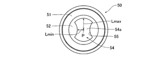
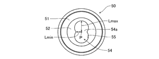
- the valve seat 50 described above includes a seat flow path 54 that has an elliptical shape when viewed in a horizontal section, but the valve seat 50 includes a seat flow path 54 that has the following shape when viewed in a horizontal section. Also good. That is, the sheet channel 54 has a saddle shape as shown in FIG. 8, a notch shape (partially deformed circular shape) as shown in FIG. 9, and a drum shape as shown in FIG. It may be formed in any one shape.
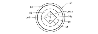
- the seat flow path 54 of the valve seat 50 is viewed in a horizontal cross section, as shown in FIG. 11 in an eccentric shape (eccentric circular shape), in a spectacle shape (overlapping circular shape) as shown in FIG. It may be formed in any one of a cross shape as shown, a square shape (rectangular shape) as shown in FIG. 14, and a triangular shape as shown in FIG.
- the sheet flow path 54 is not constant over the entire circumference of the sheet flow path inner peripheral surface 55, so that the gas has an inner peripheral surface 55 with a minimum horizontal distance L. Therefore, the gas flow is effectively generated while maintaining the sealing performance of the valve balls 31a and 31b as described above. It becomes possible to prevent.
- the shape of the seat flow path 54 of the valve seat 50 is an ellipse or the like when viewed in a horizontal section, but in addition, the seating surface 52 and the lower end surface from the central axis P If the horizontal distance L to the sheet flow path inner peripheral surface 55 excluding 53 is a shape that is not constant over the entire circumference of the sheet flow path inner peripheral surface 55 of the sheet flow path 54, various modes can be taken.
Landscapes
- Engineering & Computer Science (AREA)
- General Engineering & Computer Science (AREA)
- Mechanical Engineering (AREA)
- Check Valves (AREA)
- Lift Valve (AREA)
Priority Applications (7)
| Application Number | Priority Date | Filing Date | Title |
|---|---|---|---|
| US16/468,206 US10941868B2 (en) | 2016-12-13 | 2016-12-13 | Valve seat and valve structure |
| PCT/JP2016/087053 WO2018109839A1 (ja) | 2016-12-13 | 2016-12-13 | バルブシート及びバルブ構造 |
| EP16924198.1A EP3557099B1 (de) | 2016-12-13 | 2016-12-13 | Ventilsitz und ventilstruktur |
| DK16924198.1T DK3557099T3 (da) | 2016-12-13 | 2016-12-13 | Ventilsæde og ventilstruktur |
| JP2018556070A JP6739545B2 (ja) | 2016-12-13 | 2016-12-13 | バルブシート及びバルブ構造 |
| CN201710569221.4A CN108612852B (zh) | 2016-12-13 | 2017-07-13 | 阀座以及阀结构 |
| CN201720846866.3U CN207005305U (zh) | 2016-12-13 | 2017-07-13 | 阀座以及阀结构 |
Applications Claiming Priority (1)
| Application Number | Priority Date | Filing Date | Title |
|---|---|---|---|
| PCT/JP2016/087053 WO2018109839A1 (ja) | 2016-12-13 | 2016-12-13 | バルブシート及びバルブ構造 |
Publications (1)
| Publication Number | Publication Date |
|---|---|
| WO2018109839A1 true WO2018109839A1 (ja) | 2018-06-21 |
Family
ID=61452905
Family Applications (1)
| Application Number | Title | Priority Date | Filing Date |
|---|---|---|---|
| PCT/JP2016/087053 WO2018109839A1 (ja) | 2016-12-13 | 2016-12-13 | バルブシート及びバルブ構造 |
Country Status (6)
| Country | Link |
|---|---|
| US (1) | US10941868B2 (de) |
| EP (1) | EP3557099B1 (de) |
| JP (1) | JP6739545B2 (de) |
| CN (2) | CN207005305U (de) |
| DK (1) | DK3557099T3 (de) |
| WO (1) | WO2018109839A1 (de) |
Families Citing this family (1)
| Publication number | Priority date | Publication date | Assignee | Title |
|---|---|---|---|---|
| JP6739545B2 (ja) * | 2016-12-13 | 2020-08-12 | 株式会社イワキ | バルブシート及びバルブ構造 |
Citations (3)
| Publication number | Priority date | Publication date | Assignee | Title |
|---|---|---|---|---|
| JPH09203380A (ja) | 1996-01-26 | 1997-08-05 | Iwaki:Kk | 自動ガス抜き機構付き往復動ポンプ |
| JP2000320696A (ja) * | 1999-05-06 | 2000-11-24 | Ckd Corp | 流量調節弁 |
| JP2008128416A (ja) * | 2006-11-24 | 2008-06-05 | Toyota Motor Corp | 油圧回路 |
Family Cites Families (15)
| Publication number | Priority date | Publication date | Assignee | Title |
|---|---|---|---|---|
| US3661167A (en) * | 1970-05-25 | 1972-05-09 | A & D Fabricating Co | Chemical feed pump with improved valve means |
| US3901475A (en) * | 1974-02-28 | 1975-08-26 | Emerson Electric Co | Plastic ball seat member with constant bleed means |
| US4346731A (en) * | 1981-05-26 | 1982-08-31 | Chevron Research Company | Buoyant element check valve for a thermosiphon energy system |
| US5472326B1 (en) * | 1993-03-30 | 1999-03-02 | Leon Tarpley | Valve assemblies for sucker rod operated subsurface pumps |
| US5593292A (en) * | 1994-05-04 | 1997-01-14 | Ivey; Ray K. | Valve cage for a rod drawn positive displacement pump |
| JP2002267032A (ja) * | 2001-03-12 | 2002-09-18 | Jiro Matsuyama | ボール式逆止め弁 |
| US6755628B1 (en) * | 2002-07-16 | 2004-06-29 | Howell's Well Service, Inc. | Valve body for a traveling barrel pump |
| JP2004358574A (ja) * | 2003-06-02 | 2004-12-24 | Hirose Technology Kk | 弁座の加工方法および加工装置 |
| US7444990B1 (en) * | 2007-12-12 | 2008-11-04 | Robert Bosch Gmbh | Fuel line check valve |
| JP5210135B2 (ja) * | 2008-12-01 | 2013-06-12 | 日機装エイコー株式会社 | ガス抜き機構付き往復動ポンプ |
| US8528592B2 (en) * | 2011-02-28 | 2013-09-10 | Idex Health & Science, Llc | Check valve construction |
| JP4977791B1 (ja) * | 2011-07-01 | 2012-07-18 | 株式会社タクミナ | ポンプ及びポンプの運転方法 |
| JP5629708B2 (ja) * | 2012-03-06 | 2014-11-26 | 株式会社タクミナ | ポンプ |
| DE102012102088A1 (de) * | 2012-03-13 | 2013-09-19 | Prominent Dosiertechnik Gmbh | Verdrängerpumpe mit Zwangsentlüftung |
| JP6739545B2 (ja) * | 2016-12-13 | 2020-08-12 | 株式会社イワキ | バルブシート及びバルブ構造 |
-
2016
- 2016-12-13 JP JP2018556070A patent/JP6739545B2/ja active Active
- 2016-12-13 US US16/468,206 patent/US10941868B2/en active Active
- 2016-12-13 EP EP16924198.1A patent/EP3557099B1/de active Active
- 2016-12-13 DK DK16924198.1T patent/DK3557099T3/da active
- 2016-12-13 WO PCT/JP2016/087053 patent/WO2018109839A1/ja unknown
-
2017
- 2017-07-13 CN CN201720846866.3U patent/CN207005305U/zh not_active Expired - Fee Related
- 2017-07-13 CN CN201710569221.4A patent/CN108612852B/zh active Active
Patent Citations (3)
| Publication number | Priority date | Publication date | Assignee | Title |
|---|---|---|---|---|
| JPH09203380A (ja) | 1996-01-26 | 1997-08-05 | Iwaki:Kk | 自動ガス抜き機構付き往復動ポンプ |
| JP2000320696A (ja) * | 1999-05-06 | 2000-11-24 | Ckd Corp | 流量調節弁 |
| JP2008128416A (ja) * | 2006-11-24 | 2008-06-05 | Toyota Motor Corp | 油圧回路 |
Non-Patent Citations (1)
| Title |
|---|
| See also references of EP3557099A4 * |
Also Published As
| Publication number | Publication date |
|---|---|
| EP3557099A4 (de) | 2019-12-04 |
| EP3557099A1 (de) | 2019-10-23 |
| CN108612852A (zh) | 2018-10-02 |
| US20190390778A1 (en) | 2019-12-26 |
| DK3557099T3 (da) | 2021-09-27 |
| CN207005305U (zh) | 2018-02-13 |
| EP3557099B1 (de) | 2021-07-07 |
| JP6739545B2 (ja) | 2020-08-12 |
| CN108612852B (zh) | 2021-05-07 |
| US10941868B2 (en) | 2021-03-09 |
| JPWO2018109839A1 (ja) | 2019-10-24 |
Similar Documents
| Publication | Publication Date | Title |
|---|---|---|
| JP5138863B2 (ja) | ダイアフラム弁 | |
| TWI410575B (zh) | 流體壓力機器之閥構造 | |
| JP5706244B2 (ja) | 流体用ダイヤフラムポンプ | |
| JP2005030506A (ja) | サックバックバルブ | |
| CN111656061A (zh) | 密封垫的安装结构 | |
| US11085433B2 (en) | Diaphragm pump | |
| JP6410502B2 (ja) | 緩衝器 | |
| BR112016030309B1 (pt) | Válvula de descarga para uma bomba hidráulica de um grupo hidráulico | |
| JP6744427B2 (ja) | 往復動ポンプ | |
| WO2018109839A1 (ja) | バルブシート及びバルブ構造 | |
| US10648466B2 (en) | Piston pump for a hydraulic vehicle brake system | |
| US10648582B2 (en) | Check valve and liquid delivery pump | |
| JP2012202207A (ja) | 泡ポンプの空気弁構造 | |
| JP6326358B2 (ja) | 液体吐出容器 | |
| JP3757173B2 (ja) | ダイアフラムポンプ | |
| US10082138B2 (en) | Valve and valve seat for a diaphragm pump | |
| CN101469786A (zh) | 一种带阀套的单向阀 | |
| US20220170560A1 (en) | Valve assemblies for a diaphragm pump | |
| CN206290427U (zh) | 一种刚度可调式单向阀结构 | |
| CN106762603B (zh) | 一种刚度可调式单向阀 | |
| JP2016041910A (ja) | ダイヤフラムポンプ | |
| JP2006169993A (ja) | プランジャポンプ | |
| CN203906894U (zh) | 一种吸气止逆装置 | |
| JP5199737B2 (ja) | 液圧式ダイアフラムポンプのエア抜き弁 | |
| JP4597228B2 (ja) | 往復ポンプ装置 |
Legal Events
| Date | Code | Title | Description |
|---|---|---|---|
| 121 | Ep: the epo has been informed by wipo that ep was designated in this application |
Ref document number: 16924198 Country of ref document: EP Kind code of ref document: A1 |
|
| ENP | Entry into the national phase |
Ref document number: 2018556070 Country of ref document: JP Kind code of ref document: A |
|
| NENP | Non-entry into the national phase |
Ref country code: DE |
|
| ENP | Entry into the national phase |
Ref document number: 2016924198 Country of ref document: EP Effective date: 20190715 |