JP6739545B2 - バルブシート及びバルブ構造 - Google Patents
バルブシート及びバルブ構造 Download PDFInfo
- Publication number
- JP6739545B2 JP6739545B2 JP2018556070A JP2018556070A JP6739545B2 JP 6739545 B2 JP6739545 B2 JP 6739545B2 JP 2018556070 A JP2018556070 A JP 2018556070A JP 2018556070 A JP2018556070 A JP 2018556070A JP 6739545 B2 JP6739545 B2 JP 6739545B2
- Authority
- JP
- Japan
- Prior art keywords
- shape
- valve
- valve seat
- hole
- seat
- Prior art date
- Legal status (The legal status is an assumption and is not a legal conclusion. Google has not performed a legal analysis and makes no representation as to the accuracy of the status listed.)
- Active
Links
Images


Classifications
-
- F—MECHANICAL ENGINEERING; LIGHTING; HEATING; WEAPONS; BLASTING
- F16—ENGINEERING ELEMENTS AND UNITS; GENERAL MEASURES FOR PRODUCING AND MAINTAINING EFFECTIVE FUNCTIONING OF MACHINES OR INSTALLATIONS; THERMAL INSULATION IN GENERAL
- F16K—VALVES; TAPS; COCKS; ACTUATING-FLOATS; DEVICES FOR VENTING OR AERATING
- F16K1/00—Lift valves or globe valves, i.e. cut-off apparatus with closure members having at least a component of their opening and closing motion perpendicular to the closing faces
- F16K1/14—Lift valves or globe valves, i.e. cut-off apparatus with closure members having at least a component of their opening and closing motion perpendicular to the closing faces with ball-shaped valve member
-
- F—MECHANICAL ENGINEERING; LIGHTING; HEATING; WEAPONS; BLASTING
- F04—POSITIVE - DISPLACEMENT MACHINES FOR LIQUIDS; PUMPS FOR LIQUIDS OR ELASTIC FLUIDS
- F04B—POSITIVE-DISPLACEMENT MACHINES FOR LIQUIDS; PUMPS
- F04B53/00—Component parts, details or accessories not provided for in, or of interest apart from, groups F04B1/00 - F04B23/00 or F04B39/00 - F04B47/00
- F04B53/06—Venting
-
- F—MECHANICAL ENGINEERING; LIGHTING; HEATING; WEAPONS; BLASTING
- F04—POSITIVE - DISPLACEMENT MACHINES FOR LIQUIDS; PUMPS FOR LIQUIDS OR ELASTIC FLUIDS
- F04B—POSITIVE-DISPLACEMENT MACHINES FOR LIQUIDS; PUMPS
- F04B53/00—Component parts, details or accessories not provided for in, or of interest apart from, groups F04B1/00 - F04B23/00 or F04B39/00 - F04B47/00
- F04B53/10—Valves; Arrangement of valves
- F04B53/1002—Ball valves
- F04B53/1005—Ball valves being formed by two closure members working in series
-
- F—MECHANICAL ENGINEERING; LIGHTING; HEATING; WEAPONS; BLASTING
- F04—POSITIVE - DISPLACEMENT MACHINES FOR LIQUIDS; PUMPS FOR LIQUIDS OR ELASTIC FLUIDS
- F04B—POSITIVE-DISPLACEMENT MACHINES FOR LIQUIDS; PUMPS
- F04B53/00—Component parts, details or accessories not provided for in, or of interest apart from, groups F04B1/00 - F04B23/00 or F04B39/00 - F04B47/00
- F04B53/10—Valves; Arrangement of valves
- F04B53/1087—Valve seats
-
- F—MECHANICAL ENGINEERING; LIGHTING; HEATING; WEAPONS; BLASTING
- F16—ENGINEERING ELEMENTS AND UNITS; GENERAL MEASURES FOR PRODUCING AND MAINTAINING EFFECTIVE FUNCTIONING OF MACHINES OR INSTALLATIONS; THERMAL INSULATION IN GENERAL
- F16K—VALVES; TAPS; COCKS; ACTUATING-FLOATS; DEVICES FOR VENTING OR AERATING
- F16K1/00—Lift valves or globe valves, i.e. cut-off apparatus with closure members having at least a component of their opening and closing motion perpendicular to the closing faces
- F16K1/32—Details
- F16K1/34—Cutting-off parts, e.g. valve members, seats
- F16K1/42—Valve seats
-
- F—MECHANICAL ENGINEERING; LIGHTING; HEATING; WEAPONS; BLASTING
- F16—ENGINEERING ELEMENTS AND UNITS; GENERAL MEASURES FOR PRODUCING AND MAINTAINING EFFECTIVE FUNCTIONING OF MACHINES OR INSTALLATIONS; THERMAL INSULATION IN GENERAL
- F16K—VALVES; TAPS; COCKS; ACTUATING-FLOATS; DEVICES FOR VENTING OR AERATING
- F16K31/00—Actuating devices; Operating means; Releasing devices
- F16K31/12—Actuating devices; Operating means; Releasing devices actuated by fluid
-
- F—MECHANICAL ENGINEERING; LIGHTING; HEATING; WEAPONS; BLASTING
- F04—POSITIVE - DISPLACEMENT MACHINES FOR LIQUIDS; PUMPS FOR LIQUIDS OR ELASTIC FLUIDS
- F04B—POSITIVE-DISPLACEMENT MACHINES FOR LIQUIDS; PUMPS
- F04B13/00—Pumps specially modified to deliver fixed or variable measured quantities
-
- F—MECHANICAL ENGINEERING; LIGHTING; HEATING; WEAPONS; BLASTING
- F04—POSITIVE - DISPLACEMENT MACHINES FOR LIQUIDS; PUMPS FOR LIQUIDS OR ELASTIC FLUIDS
- F04B—POSITIVE-DISPLACEMENT MACHINES FOR LIQUIDS; PUMPS
- F04B43/00—Machines, pumps, or pumping installations having flexible working members
- F04B43/02—Machines, pumps, or pumping installations having flexible working members having plate-like flexible members, e.g. diaphragms
-
- Y—GENERAL TAGGING OF NEW TECHNOLOGICAL DEVELOPMENTS; GENERAL TAGGING OF CROSS-SECTIONAL TECHNOLOGIES SPANNING OVER SEVERAL SECTIONS OF THE IPC; TECHNICAL SUBJECTS COVERED BY FORMER USPC CROSS-REFERENCE ART COLLECTIONS [XRACs] AND DIGESTS
- Y10—TECHNICAL SUBJECTS COVERED BY FORMER USPC
- Y10T—TECHNICAL SUBJECTS COVERED BY FORMER US CLASSIFICATION
- Y10T137/00—Fluid handling
- Y10T137/7722—Line condition change responsive valves
- Y10T137/7837—Direct response valves [i.e., check valve type]
- Y10T137/7904—Reciprocating valves
- Y10T137/7908—Weight biased
- Y10T137/7909—Valve body is the weight
- Y10T137/791—Ball valves
Description
2 駆動軸
4 ダイヤフラム
5 ポンプヘッド
5a 吸込口
5b 吐出口
6 ポンプ室
8,9 接続口
10A 吸込バルブ
10B 吐出バルブ
20A,20B 接続アダプタ
29A,29B 継手
30a,30b ケース体
31a,31b バルブボール
32a,32b バルブガイド
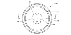
40 シートホルダ
41 嵌合部
42 支持面
43 下端面
44 ホルダ流路
45 ホルダ流路内周面
46 突条
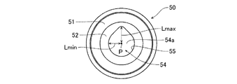
50 バルブシート
51 上端面
52 着座面
53 下端面
54 シート流路
55 シート流路内周面
Claims (7)
- バルブボールの下方に配置されるバルブシートであって、
中央に移送流体が通流する流路となる孔部を有する環状部材からなり、
前記孔部の中心軸が上下方向を向くように設置され、
前記孔部の上端と接続され前記バルブボールの外形に適合し前記バルブボールが着座する着座面及び前記孔部の下端と接続される下端面を有し、
前記孔部は、前記中心軸から前記孔部の内周面までの水平距離が、前記孔部の内周面の全周に亘って一定ではない所定形状に形成されている
ことを特徴とするバルブシート。 - 前記所定形状は、前記孔部の内周面の全周に亘った前記水平距離の最大値と最小値との差が前記最大値に対して10%以上30%以下となる形状である
ことを特徴とする請求項1記載のバルブシート。 - 前記所定形状は、水平断面で見て一部変形円形状、楕円形状、雫形状、鼓形状、偏心円形状、重複円形状、十字形状、方形状及び三角形状のいずれか一つである
ことを特徴とする請求項1又は2記載のバルブシート。 - バルブボールと、その下方に配置されたバルブシートと、このバルブシートを支持するシートホルダとを備えたバルブ構造であって、
前記バルブシートは、
中央に移送流体が通流するシート流路となる孔部を有する環状部材からなり、
前記孔部の中心軸が上下方向を向くように設置され、
前記孔部の上端と接続され前記バルブボールの外形に適合し前記バルブボールが着座する着座面及び前記孔部の下端と接続される下端面を有し、
前記シートホルダは、前記シート流路と連通するホルダ流路を有し、
前記孔部は、前記中心軸から前記孔部の内周面までの水平距離が、前記孔部の内周面の全周に亘って一定ではない所定形状に形成され、
前記ホルダ流路は、ホルダ流路内周面から前記中心軸に向かって等間隔で突出し該中心軸に沿って延びる複数の突条を有する
ことを特徴とするバルブ構造。 - 前記所定形状は、前記孔部の内周面の全周に亘った前記水平距離の最大値と最小値との差が前記最大値に対して10%以上30%以下となる形状である
ことを特徴とする請求項4記載のバルブ構造。 - 前記所定形状は、水平断面で見て一部変形円形状、楕円形状、雫形状、鼓形状、偏心円形状、重複円形状、十字形状、方形状及び三角形状のいずれか一つである
ことを特徴とする請求項4又は5記載のバルブ構造。 - 前記バルブボールは上下に2つ配置され、
前記バルブシートは各バルブボールの下方にそれぞれ配置され、
前記シートホルダは、下方のバルブシートの下端面を支持する
ことを特徴とする請求項4〜6のいずれか1項記載のバルブ構造。
Applications Claiming Priority (1)
| Application Number | Priority Date | Filing Date | Title |
|---|---|---|---|
| PCT/JP2016/087053 WO2018109839A1 (ja) | 2016-12-13 | 2016-12-13 | バルブシート及びバルブ構造 |
Publications (2)
| Publication Number | Publication Date |
|---|---|
| JPWO2018109839A1 JPWO2018109839A1 (ja) | 2019-10-24 |
| JP6739545B2 true JP6739545B2 (ja) | 2020-08-12 |
Family
ID=61452905
Family Applications (1)
| Application Number | Title | Priority Date | Filing Date |
|---|---|---|---|
| JP2018556070A Active JP6739545B2 (ja) | 2016-12-13 | 2016-12-13 | バルブシート及びバルブ構造 |
Country Status (6)
| Country | Link |
|---|---|
| US (1) | US10941868B2 (ja) |
| EP (1) | EP3557099B1 (ja) |
| JP (1) | JP6739545B2 (ja) |
| CN (2) | CN207005305U (ja) |
| DK (1) | DK3557099T3 (ja) |
| WO (1) | WO2018109839A1 (ja) |
Families Citing this family (1)
| Publication number | Priority date | Publication date | Assignee | Title |
|---|---|---|---|---|
| WO2018109839A1 (ja) * | 2016-12-13 | 2018-06-21 | 株式会社イワキ | バルブシート及びバルブ構造 |
Family Cites Families (18)
| Publication number | Priority date | Publication date | Assignee | Title |
|---|---|---|---|---|
| US3661167A (en) * | 1970-05-25 | 1972-05-09 | A & D Fabricating Co | Chemical feed pump with improved valve means |
| US3901475A (en) | 1974-02-28 | 1975-08-26 | Emerson Electric Co | Plastic ball seat member with constant bleed means |
| US4346731A (en) * | 1981-05-26 | 1982-08-31 | Chevron Research Company | Buoyant element check valve for a thermosiphon energy system |
| US5472326B1 (en) * | 1993-03-30 | 1999-03-02 | Leon Tarpley | Valve assemblies for sucker rod operated subsurface pumps |
| US5593292A (en) * | 1994-05-04 | 1997-01-14 | Ivey; Ray K. | Valve cage for a rod drawn positive displacement pump |
| JP2848807B2 (ja) | 1996-01-26 | 1999-01-20 | 株式会社イワキ | 自動ガス抜き機構付き往復動ポンプ |
| JP4365477B2 (ja) | 1999-05-06 | 2009-11-18 | シーケーディ株式会社 | 流量調節弁 |
| JP2002267032A (ja) * | 2001-03-12 | 2002-09-18 | Jiro Matsuyama | ボール式逆止め弁 |
| US6755628B1 (en) * | 2002-07-16 | 2004-06-29 | Howell's Well Service, Inc. | Valve body for a traveling barrel pump |
| JP2004358574A (ja) * | 2003-06-02 | 2004-12-24 | Hirose Technology Kk | 弁座の加工方法および加工装置 |
| JP5045071B2 (ja) | 2006-11-24 | 2012-10-10 | トヨタ自動車株式会社 | 油圧回路 |
| US7444990B1 (en) * | 2007-12-12 | 2008-11-04 | Robert Bosch Gmbh | Fuel line check valve |
| JP5210135B2 (ja) * | 2008-12-01 | 2013-06-12 | 日機装エイコー株式会社 | ガス抜き機構付き往復動ポンプ |
| US8528592B2 (en) * | 2011-02-28 | 2013-09-10 | Idex Health & Science, Llc | Check valve construction |
| JP4977791B1 (ja) * | 2011-07-01 | 2012-07-18 | 株式会社タクミナ | ポンプ及びポンプの運転方法 |
| JP5629708B2 (ja) * | 2012-03-06 | 2014-11-26 | 株式会社タクミナ | ポンプ |
| DE102012102088A1 (de) * | 2012-03-13 | 2013-09-19 | Prominent Dosiertechnik Gmbh | Verdrängerpumpe mit Zwangsentlüftung |
| WO2018109839A1 (ja) * | 2016-12-13 | 2018-06-21 | 株式会社イワキ | バルブシート及びバルブ構造 |
-
2016
- 2016-12-13 WO PCT/JP2016/087053 patent/WO2018109839A1/ja unknown
- 2016-12-13 EP EP16924198.1A patent/EP3557099B1/en active Active
- 2016-12-13 DK DK16924198.1T patent/DK3557099T3/da active
- 2016-12-13 US US16/468,206 patent/US10941868B2/en active Active
- 2016-12-13 JP JP2018556070A patent/JP6739545B2/ja active Active
-
2017
- 2017-07-13 CN CN201720846866.3U patent/CN207005305U/zh not_active Expired - Fee Related
- 2017-07-13 CN CN201710569221.4A patent/CN108612852B/zh active Active
Also Published As
| Publication number | Publication date |
|---|---|
| DK3557099T3 (da) | 2021-09-27 |
| CN108612852B (zh) | 2021-05-07 |
| JPWO2018109839A1 (ja) | 2019-10-24 |
| CN207005305U (zh) | 2018-02-13 |
| EP3557099B1 (en) | 2021-07-07 |
| WO2018109839A1 (ja) | 2018-06-21 |
| US10941868B2 (en) | 2021-03-09 |
| EP3557099A4 (en) | 2019-12-04 |
| US20190390778A1 (en) | 2019-12-26 |
| CN108612852A (zh) | 2018-10-02 |
| EP3557099A1 (en) | 2019-10-23 |
Similar Documents
| Publication | Publication Date | Title |
|---|---|---|
| KR101718822B1 (ko) | 급속 토출밸브 유닛을 일체로 구비한 다이어프램 펌프 | |
| US6651693B2 (en) | Check valve | |
| TW510947B (en) | Diaphragm breakage protection in a reciprocating diaphragm pump | |
| RU2645362C2 (ru) | Одноходовой клапан | |
| US11085433B2 (en) | Diaphragm pump | |
| CN104053907A (zh) | 用于高压清洁设备的活塞泵 | |
| JP6739545B2 (ja) | バルブシート及びバルブ構造 | |
| US10648466B2 (en) | Piston pump for a hydraulic vehicle brake system | |
| US10648582B2 (en) | Check valve and liquid delivery pump | |
| JP2012202207A (ja) | 泡ポンプの空気弁構造 | |
| JP3757173B2 (ja) | ダイアフラムポンプ | |
| CN109578254A (zh) | 泵 | |
| US20220170560A1 (en) | Valve assemblies for a diaphragm pump | |
| JP6592333B2 (ja) | 吐出用弁体およびダイヤフラムポンプ | |
| JP6393551B2 (ja) | ダイヤフラムポンプ | |
| JP5248266B2 (ja) | ポンプ | |
| JP2008180171A (ja) | マイクロポンプ | |
| JP2006169993A (ja) | プランジャポンプ | |
| JP5763486B2 (ja) | ダイヤフラムポンプ | |
| JP5199737B2 (ja) | 液圧式ダイアフラムポンプのエア抜き弁 | |
| CN213016730U (zh) | 泵 | |
| JP2019031921A (ja) | ダイヤフラムポンプ | |
| JP5352544B2 (ja) | ダイヤフラムポンプ | |
| JP6792153B2 (ja) | ダイヤフラムポンプ及び材料吐出装置 | |
| JP4878587B2 (ja) | マイクロポンプ |
Legal Events
| Date | Code | Title | Description |
|---|---|---|---|
| A621 | Written request for application examination |
Free format text: JAPANESE INTERMEDIATE CODE: A621 Effective date: 20191007 |
|
| TRDD | Decision of grant or rejection written | ||
| A01 | Written decision to grant a patent or to grant a registration (utility model) |
Free format text: JAPANESE INTERMEDIATE CODE: A01 Effective date: 20200714 |
|
| A61 | First payment of annual fees (during grant procedure) |
Free format text: JAPANESE INTERMEDIATE CODE: A61 Effective date: 20200721 |
|
| R150 | Certificate of patent or registration of utility model |
Ref document number: 6739545 Country of ref document: JP Free format text: JAPANESE INTERMEDIATE CODE: R150 |
|
| R250 | Receipt of annual fees |
Free format text: JAPANESE INTERMEDIATE CODE: R250 |