JP6739545B2 - Valve seat and valve structure - Google Patents
Valve seat and valve structure Download PDFInfo
- Publication number
- JP6739545B2 JP6739545B2 JP2018556070A JP2018556070A JP6739545B2 JP 6739545 B2 JP6739545 B2 JP 6739545B2 JP 2018556070 A JP2018556070 A JP 2018556070A JP 2018556070 A JP2018556070 A JP 2018556070A JP 6739545 B2 JP6739545 B2 JP 6739545B2
- Authority
- JP
- Japan
- Prior art keywords
- shape
- valve
- valve seat
- hole
- seat
- Prior art date
- Legal status (The legal status is an assumption and is not a legal conclusion. Google has not performed a legal analysis and makes no representation as to the accuracy of the status listed.)
- Active
Links
Images


Classifications
-
- F—MECHANICAL ENGINEERING; LIGHTING; HEATING; WEAPONS; BLASTING
- F16—ENGINEERING ELEMENTS AND UNITS; GENERAL MEASURES FOR PRODUCING AND MAINTAINING EFFECTIVE FUNCTIONING OF MACHINES OR INSTALLATIONS; THERMAL INSULATION IN GENERAL
- F16K—VALVES; TAPS; COCKS; ACTUATING-FLOATS; DEVICES FOR VENTING OR AERATING
- F16K1/00—Lift valves or globe valves, i.e. cut-off apparatus with closure members having at least a component of their opening and closing motion perpendicular to the closing faces
- F16K1/14—Lift valves or globe valves, i.e. cut-off apparatus with closure members having at least a component of their opening and closing motion perpendicular to the closing faces with ball-shaped valve member
-
- F—MECHANICAL ENGINEERING; LIGHTING; HEATING; WEAPONS; BLASTING
- F04—POSITIVE - DISPLACEMENT MACHINES FOR LIQUIDS; PUMPS FOR LIQUIDS OR ELASTIC FLUIDS
- F04B—POSITIVE-DISPLACEMENT MACHINES FOR LIQUIDS; PUMPS
- F04B53/00—Component parts, details or accessories not provided for in, or of interest apart from, groups F04B1/00 - F04B23/00 or F04B39/00 - F04B47/00
- F04B53/06—Venting
-
- F—MECHANICAL ENGINEERING; LIGHTING; HEATING; WEAPONS; BLASTING
- F04—POSITIVE - DISPLACEMENT MACHINES FOR LIQUIDS; PUMPS FOR LIQUIDS OR ELASTIC FLUIDS
- F04B—POSITIVE-DISPLACEMENT MACHINES FOR LIQUIDS; PUMPS
- F04B53/00—Component parts, details or accessories not provided for in, or of interest apart from, groups F04B1/00 - F04B23/00 or F04B39/00 - F04B47/00
- F04B53/10—Valves; Arrangement of valves
- F04B53/1002—Ball valves
- F04B53/1005—Ball valves being formed by two closure members working in series
-
- F—MECHANICAL ENGINEERING; LIGHTING; HEATING; WEAPONS; BLASTING
- F04—POSITIVE - DISPLACEMENT MACHINES FOR LIQUIDS; PUMPS FOR LIQUIDS OR ELASTIC FLUIDS
- F04B—POSITIVE-DISPLACEMENT MACHINES FOR LIQUIDS; PUMPS
- F04B53/00—Component parts, details or accessories not provided for in, or of interest apart from, groups F04B1/00 - F04B23/00 or F04B39/00 - F04B47/00
- F04B53/10—Valves; Arrangement of valves
- F04B53/1087—Valve seats
-
- F—MECHANICAL ENGINEERING; LIGHTING; HEATING; WEAPONS; BLASTING
- F16—ENGINEERING ELEMENTS AND UNITS; GENERAL MEASURES FOR PRODUCING AND MAINTAINING EFFECTIVE FUNCTIONING OF MACHINES OR INSTALLATIONS; THERMAL INSULATION IN GENERAL
- F16K—VALVES; TAPS; COCKS; ACTUATING-FLOATS; DEVICES FOR VENTING OR AERATING
- F16K1/00—Lift valves or globe valves, i.e. cut-off apparatus with closure members having at least a component of their opening and closing motion perpendicular to the closing faces
- F16K1/32—Details
- F16K1/34—Cutting-off parts, e.g. valve members, seats
- F16K1/42—Valve seats
-
- F—MECHANICAL ENGINEERING; LIGHTING; HEATING; WEAPONS; BLASTING
- F16—ENGINEERING ELEMENTS AND UNITS; GENERAL MEASURES FOR PRODUCING AND MAINTAINING EFFECTIVE FUNCTIONING OF MACHINES OR INSTALLATIONS; THERMAL INSULATION IN GENERAL
- F16K—VALVES; TAPS; COCKS; ACTUATING-FLOATS; DEVICES FOR VENTING OR AERATING
- F16K31/00—Actuating devices; Operating means; Releasing devices
- F16K31/12—Actuating devices; Operating means; Releasing devices actuated by fluid
-
- F—MECHANICAL ENGINEERING; LIGHTING; HEATING; WEAPONS; BLASTING
- F04—POSITIVE - DISPLACEMENT MACHINES FOR LIQUIDS; PUMPS FOR LIQUIDS OR ELASTIC FLUIDS
- F04B—POSITIVE-DISPLACEMENT MACHINES FOR LIQUIDS; PUMPS
- F04B13/00—Pumps specially modified to deliver fixed or variable measured quantities
-
- F—MECHANICAL ENGINEERING; LIGHTING; HEATING; WEAPONS; BLASTING
- F04—POSITIVE - DISPLACEMENT MACHINES FOR LIQUIDS; PUMPS FOR LIQUIDS OR ELASTIC FLUIDS
- F04B—POSITIVE-DISPLACEMENT MACHINES FOR LIQUIDS; PUMPS
- F04B43/00—Machines, pumps, or pumping installations having flexible working members
- F04B43/02—Machines, pumps, or pumping installations having flexible working members having plate-like flexible members, e.g. diaphragms
-
- Y—GENERAL TAGGING OF NEW TECHNOLOGICAL DEVELOPMENTS; GENERAL TAGGING OF CROSS-SECTIONAL TECHNOLOGIES SPANNING OVER SEVERAL SECTIONS OF THE IPC; TECHNICAL SUBJECTS COVERED BY FORMER USPC CROSS-REFERENCE ART COLLECTIONS [XRACs] AND DIGESTS
- Y10—TECHNICAL SUBJECTS COVERED BY FORMER USPC
- Y10T—TECHNICAL SUBJECTS COVERED BY FORMER US CLASSIFICATION
- Y10T137/00—Fluid handling
- Y10T137/7722—Line condition change responsive valves
- Y10T137/7837—Direct response valves [i.e., check valve type]
- Y10T137/7904—Reciprocating valves
- Y10T137/7908—Weight biased
- Y10T137/7909—Valve body is the weight
- Y10T137/791—Ball valves
Landscapes
- Engineering & Computer Science (AREA)
- General Engineering & Computer Science (AREA)
- Mechanical Engineering (AREA)
- Check Valves (AREA)
- Lift Valve (AREA)
Description
本発明は、バルブシート及びバルブ構造に関する。 The present invention relates to a valve seat and a valve structure.
移送流体を移送するポンプ装置は、マグネットポンプ装置、定量ポンプ装置、回転容積型ポンプ装置等の種々のものが知られている。その中で、例えばダイヤフラム等の往復動部材の往復動によって吸込弁を介してポンプ室内に移送流体を導入し、吐出弁を介してポンプ室から移送流体を吐出する定量ポンプ装置としての往復動ポンプには、吸込弁や吐出弁としてボールバルブが採用されている。このボールバルブは、ポンプ室内に移送流体から発生したガスや移送流体と共に吸入された空気等のガスがバルブの下部に滞留すると、ガスロック状態となることが知られている。 Various pump devices for transferring the transfer fluid are known, such as a magnet pump device, a metering pump device, and a rotary positive displacement pump device. Among them, a reciprocating pump as a metering pump device that introduces a transfer fluid into a pump chamber through a suction valve by the reciprocating motion of a reciprocating member such as a diaphragm and discharges the transfer fluid from the pump chamber through a discharge valve. Uses a ball valve as a suction valve and a discharge valve. It is known that this ball valve is in a gas lock state when a gas generated from the transfer fluid in the pump chamber or a gas such as air sucked together with the transfer fluid stays in the lower portion of the valve.
このようなガスロックを防止するために、自動ガス抜き機構を備えた往復動ポンプが提案されている(下記特許文献1参照)。この往復動ポンプでは、吐出弁の直後の通路を吐出口まで水平に延びる吐出液通路と直上に延びるガス抜き通路とに分岐している。そして、ガス抜き通路にガス抜き弁を配置し、ガス抜き弁を1つのボールバルブとその上下に配置されたバルブシートとにより構成している。
In order to prevent such a gas lock, a reciprocating pump provided with an automatic degassing mechanism has been proposed (see
このガス抜き弁は、バルブボールとその上方のバルブシートとが密着性を意図的に悪くした不完全シールとなるように構成されている。このため、吸入ストローク時にはバルブボールと下側のバルブシートとにより通常のボールチャッキ弁と同様に外部から液やガスの漏れ込みが防止される。反対に、吐出ストローク時には、僅かに液中に混入したガスがバルブボールと上側のバルブシートとの間の不完全シールを介して外部に効率よく排出される。 This gas vent valve is configured so that the valve ball and the valve seat above the valve ball form an incomplete seal in which adhesion is intentionally deteriorated. Therefore, at the time of the suction stroke, the valve ball and the lower valve seat prevent liquid or gas from leaking from the outside, as in a normal ball check valve. On the contrary, during the discharge stroke, the gas slightly mixed in the liquid is efficiently discharged to the outside through the incomplete seal between the valve ball and the upper valve seat.
しかしながら、上記特許文献1に開示された従来技術の往復動ポンプでは、バルブボールと上側のバルブシートとが不完全シールを構成している。このため、ガスロックの防止という観点からは好ましい形態であるものの、バルブボールのシール性という観点からは決して好ましい形態とは言い難かった。
However, in the conventional reciprocating pump disclosed in
本発明は、上記事情に鑑みてなされたもので、バルブボールのシール性を維持したままガスロックの発生を防止することができるバルブシート及びバルブ構造を提供することを目的とする。 The present invention has been made in view of the above circumstances, and an object of the present invention is to provide a valve seat and a valve structure capable of preventing the occurrence of a gas lock while maintaining the sealing property of a valve ball.
本発明に係るバルブシートは、バルブボールの下方に配置されるバルブシートであって、中央に移送流体が通流する流路となる孔部を有する環状部材からなり、前記孔部の中心軸が上下方向を向くように設置され、前記孔部の上端と接続され前記バルブボールの外形に適合し前記バルブボールが着座する着座面及び前記孔部の下端と接続される下端面を有し、前記孔部は、前記中心軸から前記孔部の内周面までの水平距離が、前記孔部の内周面の全周に亘って一定ではない所定形状に形成されていることを特徴とする。 A valve seat according to the present invention is a valve seat disposed below a valve ball, and is composed of an annular member having a hole portion that serves as a flow path through which a transfer fluid flows in the center, and the central axis of the hole portion is Installed so as to face up and down, having a seating surface connected to the upper end of the hole and adapted to the outer shape of the valve ball and on which the valve ball is seated, and a lower end surface connected to the lower end of the hole, The hole is formed in a predetermined shape in which a horizontal distance from the central axis to the inner peripheral surface of the hole is not constant over the entire circumference of the inner peripheral surface of the hole.
本発明の一実施形態においては、前記所定形状は、前記孔部の内周面の全周に亘った前記水平距離の最大値と最小値との差が前記最大値に対して10%以上30%以下となる形状である。 In one embodiment of the present invention, in the predetermined shape, the difference between the maximum value and the minimum value of the horizontal distance over the entire circumference of the inner peripheral surface of the hole is 10% or more with respect to the maximum value. The shape is less than or equal to %.
本発明の他の実施形態においては、前記所定形状は、水平断面で見て一部変形円形状、楕円形状、雫形状、鼓形状、偏心円形状、重複円形状、十字形状、方形状及び三角形状のいずれか一つである。 In another embodiment of the present invention, the predetermined shape is a partially deformed circular shape, an oval shape, a drop shape, an hourglass shape, an eccentric circular shape, an overlapping circular shape, a cross shape, a rectangular shape and a triangular shape when viewed in a horizontal cross section. It is one of the shapes.
本発明に係るバルブ構造は、バルブボールと、その下方に配置されたバルブシートと、このバルブシートを支持するシートホルダとを備えたバルブ構造であって、前記バルブシートは、中央に移送流体が通流するシート流路となる孔部を有する環状部材からなり、前記孔部の中心軸が上下方向を向くように設置され、前記孔部の上端と接続され前記バルブボールの外形に適合し前記バルブボールが着座する着座面及び前記孔部の下端と接続される下端面を有し、前記シートホルダは、前記シート流路と連通するホルダ流路を有し、前記孔部は、前記中心軸から前記孔部の内周面までの水平距離が、前記孔部の内周面の全周に亘って一定ではない所定形状に形成され、前記ホルダ流路は、ホルダ流路内周面から前記中心軸に向かって突出し該中心軸に沿って延びる複数の突条を有することを特徴とする。 A valve structure according to the present invention is a valve structure including a valve ball, a valve seat disposed below the valve ball, and a seat holder supporting the valve seat, wherein the valve seat has a transfer fluid at a center thereof. It is composed of an annular member having a hole portion that serves as a sheet flow path that flows, is installed so that the central axis of the hole portion faces the up-down direction, is connected to the upper end of the hole portion, and conforms to the outer shape of the valve ball, The seat has a seating surface on which the valve ball is seated and a lower end surface connected to the lower end of the hole, the seat holder has a holder channel communicating with the seat channel, and the hole has the central axis. The horizontal distance from the hole to the inner peripheral surface of the hole is formed in a predetermined shape that is not constant over the entire circumference of the inner peripheral surface of the hole. It is characterized by having a plurality of ridges protruding toward the central axis and extending along the central axis.
本発明の一実施形態においては、前記所定形状は、前記孔部の内周面の全周に亘った前記水平距離の最大値と最小値との差が前記最大値に対して10%以上30%以下となる形状である。 In one embodiment of the present invention, in the predetermined shape, the difference between the maximum value and the minimum value of the horizontal distance over the entire circumference of the inner peripheral surface of the hole is 10% or more with respect to the maximum value. The shape is less than or equal to %.
本発明の他の実施形態においては、前記所定形状は、水平断面で見て一部変形円形状、楕円形状、雫形状、鼓形状、偏心円形状、重複円形状、十字形状、方形状及び三角形状のいずれか一つである。 In another embodiment of the present invention, the predetermined shape is a partially deformed circular shape, an oval shape, a drop shape, an hourglass shape, an eccentric circular shape, an overlapping circular shape, a cross shape, a rectangular shape and a triangular shape when viewed in a horizontal cross section. It is one of the shapes.
本発明の更に他の実施形態においては、前記バルブボールは上下に2つ配置され、前記バルブシートは各バルブボールの下方にそれぞれ配置され、前記シートホルダは、下方のバルブシートの下端面を支持する。 In still another embodiment of the present invention, the two valve balls are arranged above and below, the valve seats are arranged below the respective valve balls, and the seat holder supports a lower end surface of the lower valve seat. To do.
本発明によれば、バルブボールのシール性を維持したままガスロックの発生を防止することができる。 According to the present invention, the occurrence of gas lock can be prevented while maintaining the sealing property of the valve ball.
以下、添付の図面を参照して、本発明の実施の形態に係るバルブシート及びバルブ構造を詳細に説明する。ただし、以下の実施の形態は、各請求項に係る発明を限定するものではなく、また、実施の形態の中で説明されている特徴の組み合わせの全てが発明の解決手段に必須であるとは限らない。なお、以下の実施の形態は、本発明に係るバルブ構造を吸込バルブ及び吐出バルブに適用することで定量ポンプとして構成した場合を例示するものであり、その構成部材として本発明に係るバルブシートを含んだものであるが、本発明はポンプ装置に限定されるものではない。 Hereinafter, a valve seat and a valve structure according to embodiments of the present invention will be described in detail with reference to the accompanying drawings. However, the following embodiments are not intended to limit the invention according to each claim, and all combinations of the features described in the embodiments are essential to the solution means of the invention. Not exclusively. The following embodiments exemplify a case where the valve structure according to the present invention is applied to a suction valve and a discharge valve to constitute a metering pump, and the valve seat according to the present invention is used as a constituent member thereof. Although included, the present invention is not limited to pumping devices.
図1は、本発明の一実施形態に係るバルブシート50及びバルブ構造が適用された往復動ポンプの要部を示す断面図である。また、図2は、この往復動ポンプのバルブシート50を示す斜視図であり、図3はバルブシート50を示す平面図である。また、図4は、図3のA−A’線断面図であり、図5は図3のB−B’線断面図である。更に、図6は、この往復動ポンプのシートホルダ40を示す平面図であり、図7は図6のC−C’線断面図である。
FIG. 1 is a sectional view showing an essential part of a reciprocating pump to which a
図1に示すように、本発明の一実施形態に係るバルブシート50及びバルブ構造を備えた定量ポンプ1は、例えば棒状の駆動軸2を有する。駆動軸2は、図示しないポンプ本体のモータ駆動力や電磁力等によって図中矢印で示す方向に往復駆動される。駆動軸2の先端には、可撓性のダイヤフラム4がインサートボルト3を介して装着されている。
As shown in FIG. 1, a
ダイヤフラム4は、ポンプヘッド5との間にポンプ室6を形成している。ポンプ室6には、液体及び気体を含む移送流体が導入され、排出される。このダイヤフラム4は、その周縁部が、ポンプヘッド5とブラケット7との間にダイヤフラム4のシールをアシストするクッション材7a及びスペーサ7bを介して挟持されている。ポンプヘッド5には、ポンプ室6の下方に連通する吸込口5aと、ポンプ室6の上方に連通する吐出口5bとが形成されている。なお、ポンプ室6の上方には吐出口5bに繋がるガス抜き通路90が設けられている。
The
また、ポンプヘッド5には、吸込口5aの下方に配置された移送流体の吸込側の接続口8と、吐出口5bの上方に配置された吐出側の接続口9とが形成されている。これらの接続口8,9は、それぞれ吸込口5a及び吐出口5bを介してポンプ室6と連通されている。各接続口8,9には、吸込バルブ10A及び吐出バルブ10Bを介して接続アダプタ20A,20Bがそれぞれ接続される。
Further, the
また、これら接続アダプタ20A,20Bは、移送流体の吸込側流路29aを接続アダプタ20Aに接続する継手29Aと、移送流体の吐出側流路29bを接続アダプタ20Bに接続する継手29Bとそれぞれ接続されている。これにより、吸込側流路29a及びポンプ室6は、継手29A、接続アダプタ20A、吸込バルブ10A及び接続口8上の吸込口5aを介して接続される。また、吐出側流路29b及びポンプ室6は、継手29B、接続アダプタ20B、吐出バルブ10B及び接続口9下の吐出口5bを介して接続される。
Further, these
吸込バルブ10A及び吐出バルブ10Bは、例えば円筒状に形成され上下に組み合わせ可能なケース体30a,30bと、このケース体30a,30bに内蔵された2つのバルブボール31a,31bとを有する。また、吸込及び吐出バルブ10A,10Bは、各ケース体30a,30bの内部において、各バルブボール31a,31bの上方に配置形成されたバルブガイド32a,32bと、バルブボール31a,31bの下方に配置されケース体30a,30bに取り付けられたバルブシート50とを有する。従って、本実施形態の吸込及び吐出バルブ10A,10Bは、これらの各部がそれぞれ上下2段に配置された2段ボールバルブからなる。また、吸込バルブ10A及び吐出バルブ10Bは、それぞれ下方のバルブシート50を支持しケース体30bの下端側に取り付けられるシートホルダ40を備えている。
The
バルブボール31a,31bは、移送流体よりも比重の大きい、例えばセラミックスや金属からなるものを用いることができる。また、バルブガイド32a,32bは、チタンやPVC等の材料により形成することができる。更に、バルブシート50は、ゴム系材料等により形成することができる。
The
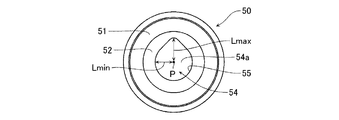
図2〜図5に示すように、バルブシート50は、中央に孔部54aを有し、外径が上端から下端にかけて順次大きくなる環状部材からなる。バルブシート50は、円形平面状の上端面51と、バルブボール31a,31bの外形と適合し、バルブボール31a,31bが着座するテーパ状やすり鉢状に形成された着座面52と、上端面51と同じく円形平面状の下端面53とを有する。
As shown in FIGS. 2 to 5, the
また、バルブシート50の孔部54aは、着座面52と下端面53とを連絡し、内部に移送流体が通流するシート流路54を形成する。なお、シート流路54と下端面53との間には、図4及び図5に示すように、移送流体中の気体が溜まるガス溜り部53aが形成されている。シート流路54は、例えば下端面53と直交する中心軸Pから着座面52及び下端面53を除くシート流路内周面55までの水平距離Lが、シート流路54のシート流路内周面55の全周に亘って(360°に亘って)一定ではない所定形状に形成されている。
Further, the
なお、シート流路54の所定形状とは、図3に示すように、好ましくはシート流路54のシート流路内周面55の全周に亘った中心軸Pからの水平距離Lの最大値Lmaxと最小値Lminとの差が、例えば最大値Lmaxに対して10%以上30%以下、好ましくは15%以上20%以下となるように形成された形状のことをいう。図2〜図5に示すシート流路54は、具体的には、水平断面で見て楕円形状となるように形成されている。
The predetermined shape of the
ここで、一般的なバルブシートは、着座面及びシート流路が共に同心の円形状に形成されている。このため、バルブシートの下方或いはガス溜り部に気体が滞留した状態でポンプ装置を稼働すると、バルブボールの下方においてシート流路の内周面の全周に亘って環状に気体が拡がりバルブボールを持ち上げようとする。 Here, in a general valve seat, the seating surface and the seat channel are both formed in a concentric circular shape. Therefore, when the pump device is operated under the valve seat or in the state where the gas is accumulated in the gas reservoir, the gas spreads in an annular shape over the entire circumference of the inner peripheral surface of the seat flow path below the valve ball, and the valve ball is spread. I try to lift.
この場合、バルブボールを持ち上げようとする力が全周に亘って分散してしまうと共に、結果的に移送流体中の気体の混入が多量であった場合には、ポンプ装置による移送流体の圧縮力が不足してしまいガスロック状態となってしまうことが多々あった。 In this case, when the force to lift the valve ball is dispersed over the entire circumference and, as a result, a large amount of gas is mixed in the transfer fluid, the compressing force of the transfer fluid by the pump device. There was often a shortage of gas, resulting in a gas lock.
これに対し、本実施形態のバルブシート50は、バルブボール31a,31bと着座面52とが完全シールを形成する一方、上述したようにシート流路54がシート流路内周面55の全周に亘って一定ではない形状で形成されている。このため、バルブシート50の下方に滞留した移送流体中の気体はガス溜り部53aに集まり、この気体がガス溜り部53aからシート流路54を上昇する際に、上記水平距離Lが最小値となるシート流路内周面55の方よりも、最大値となるシート流路内周面55の方へ集中して上昇する。
On the other hand, in the
これにより、定量ポンプ1による移送流体の圧縮力が小さくても、バルブシート50の着座面52に着座して密着したバルブボール31a,31bを、シート流路54を局所的に通過する気体により十分に持ち上げることができるので、この気体をバルブガイド32a,32bの方へ排出することが可能となる。従って、本実施形態のバルブシート50によれば、バルブボール31a,31bのシール性を維持したままガスロックの発生を効果的に防止することができる。
As a result, even if the compressive force of the fluid transferred by the
ここで、シート流路54の所定形状について、中心軸Pからの水平距離Lの最大値Lmaxと最小値Lminとの差が最大値Lmaxに対して10%以上30%以下とした根拠について説明する。すなわち、水平距離Lの最大値Lmaxと最小値Lminとの差が大きい場合には、バルブシート50とバルブボール31a,31bのシール性を確保するために最小値Lminを小さく設定する必要が生じ、この場合は結果としてシート流路54の面積が小さくなる。そして、流路面積が小さくなると、移送流体がシート流路54内を通流する際に抵抗が大きくなるため、ポンプの性能の観点から見ると好ましくない。
Here, the reason why the difference between the maximum value Lmax and the minimum value Lmin of the horizontal distance L from the central axis P for the predetermined shape of the
一方、水平距離Lの最大値Lmaxと最小値Lminとの差が小さい場合には、上述したようにバルブボール31a,31bの下方で水平距離Lが最大値Lmaxとなるシート流路内周面55の方へ気体を集中させる効果が低くなり、この場合は結果としてガスロックの発生を防止する効果が低くなるので好ましくない。従って、ポンプ性能への影響を考慮しながらガスロック発生の防止効果を高めることを追求した、本発明者の鋭意努力による実験の結果、上記のような差が最大値Lmaxに対して「10%以上30%以下」、好ましくは「15%以上20%以下」となることが導き出された。
On the other hand, when the difference between the maximum value Lmax and the minimum value Lmin of the horizontal distance L is small, as described above, the inner
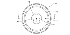
なお、図6及び図7に示すように、シートホルダ40は、吸込バルブ10A及び吐出バルブ10Bにおいて最も下方に配置されるバルブシート50の下端面53を支持するものであり、円筒状の外観を備えて形成され、ケース体30bの下方に嵌合する凹状の嵌合部41を有する。この嵌合部41の底面は、バルブシート50の下端面53を面接触により支持する支持面42を構成する。
As shown in FIGS. 6 and 7, the
シートホルダ40は、支持面42と下端面43とを連絡すると共に内部に移送流体が通流し、バルブシート50のシート流路54と連通するホルダ流路44を有する。このホルダ流路44は、バルブシート50の中心軸Pと同じ中心軸Pを有する。ホルダ流路44は、ホルダ流路内周面45からこの中心軸Pに向かって突出し、且つこの中心軸Pに沿って延びる複数の突条46を有する。
The
このように構成されたシートホルダ40においては、シートホルダ40の下方から移送されてくる移送流体中の気体が、ホルダ流路44を上昇する際にホルダ流路内周面45の全周に亘って環状に拡がることなく、各突条46の間の部分へ集中して上昇する。そして、ホルダ流路内周面45の各突条46間に局所的に集中した気体は、バルブシート50のガス溜り部53aへ複数の流れとなって入り込み、シート流路54内を上昇する。
In the
このように、シートホルダ40のホルダ流路44内において、突条46により予めバルブシート50のガス溜り部53aに滞留する気体の流れを確保するようにしている。これにより、バルブシート50を単体で用いる効果にプラスして、気体がシート流路54のシート流路内周面55の全周に亘って環状に拡がって、結果的にバルブボール31a,31bを持ち上げようとする力が分散してしまうことをより確実に防止することが期待できる。このように、突条46が形成されたホルダ流路内周面45を有するシートホルダ40を用いれば、本実施形態のバルブシート50の作用効果をより一層高めることが可能となる。
As described above, in the
図8〜図15は、上述したバルブシート50の変形例を示す平面図である。上述したバルブシート50は、水平断面で見て楕円形状となるシート流路54を備えていたが、バルブシート50は、水平断面で見て次のような形状のシート流路54を備えていてもよい。すなわち、シート流路54は、水平断面で見て、それぞれ図8に示すような雫形状、図9に示すような切欠形状(一部変形円形状)、及び図10に示すような鼓形状のいずれか一つの形状で形成されていてもよい。
8 to 15 are plan views showing modified examples of the
また、バルブシート50のシート流路54は、水平断面で見て、それぞれ図11に示すような偏心形状(偏心円形状)、図12に示すような眼鏡形状(重複円形状)、図13に示すような十字形状、図14に示すような方形状(矩形状)、及び図15に示すような三角形状のいずれか一つの形状で形成されていてもよい。
Further, the
上記いずれの形状であっても、シート流路54がシート流路内周面55の全周に亘って一定とはならないので、気体は水平距離Lが最小値となるシート流路内周面55の方よりも、最大値となるシート流路内周面55の方へ集中して上昇するため、上述したようにバルブボール31a,31bのシール性を維持したままガスロックの発生を効果的に防止することが可能となる。
In any of the above shapes, the
以上、本発明の実施の形態を説明したが、この実施の形態は例として提示したものであり、発明の範囲を限定することは意図していない。この新規な実施の形態は、その他の様々な形態で実施されることが可能であり、発明の要旨を逸脱しない範囲で、種々の省略、置き換え、変更を行うことができる。この実施の形態やその変形は、発明の範囲や要旨に含まれると共に、特許請求の範囲に記載された発明とその均等の範囲に含まれる。 Although the embodiment of the present invention has been described above, this embodiment is presented as an example and is not intended to limit the scope of the invention. This novel embodiment can be implemented in various other forms, and various omissions, replacements, and changes can be made without departing from the gist of the invention. This embodiment and its modifications are included in the scope and gist of the invention, and are also included in the invention described in the claims and the scope equivalent thereto.
例えば、上記の実施の形態では、バルブシート50のシート流路54の形状を、水平断面で見て楕円形状等となるものとしたが、その他にも、中心軸Pから着座面52及び下端面53を除くシート流路内周面55までの水平距離Lが、シート流路54のシート流路内周面55の全周に亘って一定ではない形状であれば、種々の態様を取り得る。
For example, in the above-described embodiment, the shape of the
1 定量ポンプ
2 駆動軸
4 ダイヤフラム
5 ポンプヘッド
5a 吸込口
5b 吐出口
6 ポンプ室
8,9 接続口
10A 吸込バルブ
10B 吐出バルブ
20A,20B 接続アダプタ
29A,29B 継手
30a,30b ケース体
31a,31b バルブボール
32a,32b バルブガイド
40 シートホルダ
41 嵌合部
42 支持面
43 下端面
44 ホルダ流路
45 ホルダ流路内周面
46 突条
50 バルブシート
51 上端面
52 着座面
53 下端面
54 シート流路
55 シート流路内周面1
Claims (7)
中央に移送流体が通流する流路となる孔部を有する環状部材からなり、
前記孔部の中心軸が上下方向を向くように設置され、
前記孔部の上端と接続され前記バルブボールの外形に適合し前記バルブボールが着座する着座面及び前記孔部の下端と接続される下端面を有し、
前記孔部は、前記中心軸から前記孔部の内周面までの水平距離が、前記孔部の内周面の全周に亘って一定ではない所定形状に形成されている
ことを特徴とするバルブシート。A valve seat arranged below the valve ball,
It consists of an annular member with a hole that serves as a flow path for the transfer fluid to flow in the center,
The central axis of the hole is installed in the vertical direction,
A seating surface that is connected to the upper end of the hole and that conforms to the outer shape of the valve ball and on which the valve ball is seated; and a lower end surface that is connected to the lower end of the hole,
The hole portion is formed in a predetermined shape in which the horizontal distance from the central axis to the inner peripheral surface of the hole portion is not constant over the entire circumference of the inner peripheral surface of the hole portion. Valve seat.
ことを特徴とする請求項1記載のバルブシート。The predetermined shape is a shape in which the difference between the maximum value and the minimum value of the horizontal distance over the entire circumference of the inner peripheral surface of the hole is 10% or more and 30% or less with respect to the maximum value. The valve seat according to claim 1, wherein the valve seat is a valve seat.
ことを特徴とする請求項1又は2記載のバルブシート。The predetermined shape is one of a partially deformed circular shape, an elliptical shape, a drop shape, an hourglass shape, an eccentric circular shape, an overlapping circular shape, a cross shape, a square shape and a triangular shape when viewed in a horizontal cross section. The valve seat according to claim 1 or 2, which is characterized.
前記バルブシートは、
中央に移送流体が通流するシート流路となる孔部を有する環状部材からなり、
前記孔部の中心軸が上下方向を向くように設置され、
前記孔部の上端と接続され前記バルブボールの外形に適合し前記バルブボールが着座する着座面及び前記孔部の下端と接続される下端面を有し、
前記シートホルダは、前記シート流路と連通するホルダ流路を有し、
前記孔部は、前記中心軸から前記孔部の内周面までの水平距離が、前記孔部の内周面の全周に亘って一定ではない所定形状に形成され、
前記ホルダ流路は、ホルダ流路内周面から前記中心軸に向かって等間隔で突出し該中心軸に沿って延びる複数の突条を有する
ことを特徴とするバルブ構造。A valve structure comprising a valve ball, a valve seat arranged below the valve ball, and a seat holder supporting the valve seat,
The valve seat is
It consists of an annular member with a hole that becomes a sheet channel through which the transfer fluid flows in the center,
The central axis of the hole is installed in the vertical direction,
A seating surface that is connected to the upper end of the hole and that conforms to the outer shape of the valve ball and on which the valve ball is seated; and a lower end surface that is connected to the lower end of the hole,
The sheet holder has a holder channel that communicates with the sheet channel,
The hole portion, the horizontal distance from the central axis to the inner peripheral surface of the hole portion is formed in a predetermined shape that is not constant over the entire circumference of the inner peripheral surface of the hole portion,
The valve structure, wherein the holder flow path has a plurality of protrusions that project from the inner peripheral surface of the holder flow path toward the central axis at equal intervals and extend along the central axis.
ことを特徴とする請求項4記載のバルブ構造。The predetermined shape is a shape in which the difference between the maximum value and the minimum value of the horizontal distance over the entire circumference of the inner peripheral surface of the hole is 10% or more and 30% or less with respect to the maximum value. The valve structure according to claim 4, which is characterized in that.
ことを特徴とする請求項4又は5記載のバルブ構造。The predetermined shape is one of a partially deformed circular shape, an elliptical shape, a drop shape, an hourglass shape, an eccentric circular shape, an overlapping circular shape, a cross shape, a square shape and a triangular shape when viewed in a horizontal cross section. The valve structure according to claim 4 or 5, which is characterized.
前記バルブシートは各バルブボールの下方にそれぞれ配置され、
前記シートホルダは、下方のバルブシートの下端面を支持する
ことを特徴とする請求項4〜6のいずれか1項記載のバルブ構造。
The two valve balls are arranged one above the other,
The valve seat is arranged below each valve ball,
The valve structure according to any one of claims 4 to 6, wherein the seat holder supports a lower end surface of a lower valve seat.
Applications Claiming Priority (1)
| Application Number | Priority Date | Filing Date | Title |
|---|---|---|---|
| PCT/JP2016/087053 WO2018109839A1 (en) | 2016-12-13 | 2016-12-13 | Valve seat and valve structure |
Publications (2)
| Publication Number | Publication Date |
|---|---|
| JPWO2018109839A1 JPWO2018109839A1 (en) | 2019-10-24 |
| JP6739545B2 true JP6739545B2 (en) | 2020-08-12 |
Family
ID=61452905
Family Applications (1)
| Application Number | Title | Priority Date | Filing Date |
|---|---|---|---|
| JP2018556070A Active JP6739545B2 (en) | 2016-12-13 | 2016-12-13 | Valve seat and valve structure |
Country Status (6)
| Country | Link |
|---|---|
| US (1) | US10941868B2 (en) |
| EP (1) | EP3557099B1 (en) |
| JP (1) | JP6739545B2 (en) |
| CN (2) | CN207005305U (en) |
| DK (1) | DK3557099T3 (en) |
| WO (1) | WO2018109839A1 (en) |
Families Citing this family (1)
| Publication number | Priority date | Publication date | Assignee | Title |
|---|---|---|---|---|
| DK3557099T3 (en) * | 2016-12-13 | 2021-09-27 | Iwaki Co Ltd | Valve seat and valve structure |
Family Cites Families (18)
| Publication number | Priority date | Publication date | Assignee | Title |
|---|---|---|---|---|
| US3661167A (en) * | 1970-05-25 | 1972-05-09 | A & D Fabricating Co | Chemical feed pump with improved valve means |
| US3901475A (en) * | 1974-02-28 | 1975-08-26 | Emerson Electric Co | Plastic ball seat member with constant bleed means |
| US4346731A (en) * | 1981-05-26 | 1982-08-31 | Chevron Research Company | Buoyant element check valve for a thermosiphon energy system |
| US5472326B1 (en) * | 1993-03-30 | 1999-03-02 | Leon Tarpley | Valve assemblies for sucker rod operated subsurface pumps |
| US5593292A (en) * | 1994-05-04 | 1997-01-14 | Ivey; Ray K. | Valve cage for a rod drawn positive displacement pump |
| JP2848807B2 (en) | 1996-01-26 | 1999-01-20 | 株式会社イワキ | Reciprocating pump with automatic degassing mechanism |
| JP4365477B2 (en) * | 1999-05-06 | 2009-11-18 | シーケーディ株式会社 | Flow control valve |
| JP2002267032A (en) * | 2001-03-12 | 2002-09-18 | Jiro Matsuyama | Ball check valve |
| US6755628B1 (en) | 2002-07-16 | 2004-06-29 | Howell's Well Service, Inc. | Valve body for a traveling barrel pump |
| JP2004358574A (en) * | 2003-06-02 | 2004-12-24 | Hirose Technology Kk | Machining method and machining device for valve seat |
| JP5045071B2 (en) * | 2006-11-24 | 2012-10-10 | トヨタ自動車株式会社 | Hydraulic circuit |
| US7444990B1 (en) * | 2007-12-12 | 2008-11-04 | Robert Bosch Gmbh | Fuel line check valve |
| JP5210135B2 (en) * | 2008-12-01 | 2013-06-12 | 日機装エイコー株式会社 | Reciprocating pump with degassing mechanism |
| US8528592B2 (en) * | 2011-02-28 | 2013-09-10 | Idex Health & Science, Llc | Check valve construction |
| JP4977791B1 (en) * | 2011-07-01 | 2012-07-18 | 株式会社タクミナ | Pump and pump operation method |
| JP5629708B2 (en) * | 2012-03-06 | 2014-11-26 | 株式会社タクミナ | pump |
| DE102012102088A1 (en) * | 2012-03-13 | 2013-09-19 | Prominent Dosiertechnik Gmbh | Positive displacement pump with forced ventilation |
| DK3557099T3 (en) * | 2016-12-13 | 2021-09-27 | Iwaki Co Ltd | Valve seat and valve structure |
-
2016
- 2016-12-13 DK DK16924198.1T patent/DK3557099T3/en active
- 2016-12-13 EP EP16924198.1A patent/EP3557099B1/en active Active
- 2016-12-13 JP JP2018556070A patent/JP6739545B2/en active Active
- 2016-12-13 WO PCT/JP2016/087053 patent/WO2018109839A1/en unknown
- 2016-12-13 US US16/468,206 patent/US10941868B2/en active Active
-
2017
- 2017-07-13 CN CN201720846866.3U patent/CN207005305U/en not_active Expired - Fee Related
- 2017-07-13 CN CN201710569221.4A patent/CN108612852B/en active Active
Also Published As
| Publication number | Publication date |
|---|---|
| CN108612852B (en) | 2021-05-07 |
| EP3557099B1 (en) | 2021-07-07 |
| CN207005305U (en) | 2018-02-13 |
| US10941868B2 (en) | 2021-03-09 |
| EP3557099A1 (en) | 2019-10-23 |
| DK3557099T3 (en) | 2021-09-27 |
| US20190390778A1 (en) | 2019-12-26 |
| EP3557099A4 (en) | 2019-12-04 |
| CN108612852A (en) | 2018-10-02 |
| WO2018109839A1 (en) | 2018-06-21 |
| JPWO2018109839A1 (en) | 2019-10-24 |
Similar Documents
| Publication | Publication Date | Title |
|---|---|---|
| US6651693B2 (en) | Check valve | |
| TW510947B (en) | Diaphragm breakage protection in a reciprocating diaphragm pump | |
| TWI591256B (en) | Diaphragm pump integrally including quick discharge valve unit | |
| RU2645362C2 (en) | One way valve | |
| CN104053907A (en) | Piston pump for a high-pressure cleaning device | |
| JP6739545B2 (en) | Valve seat and valve structure | |
| US10648466B2 (en) | Piston pump for a hydraulic vehicle brake system | |
| US10648582B2 (en) | Check valve and liquid delivery pump | |
| JP2012202207A (en) | Air valve structure of foam pump | |
| JP3757173B2 (en) | Diaphragm pump | |
| CN109578254A (en) | Pump | |
| US20220170560A1 (en) | Valve assemblies for a diaphragm pump | |
| JP6592333B2 (en) | Discharge valve body and diaphragm pump | |
| JP6393551B2 (en) | Diaphragm pump | |
| JP5248266B2 (en) | pump | |
| JP2008180171A (en) | Micro pump | |
| JP2006169993A (en) | Plunger pump | |
| JP5199737B2 (en) | Air bleeding valve for hydraulic diaphragm pump | |
| JP6726956B2 (en) | Valve structure of reciprocating pump and degassing valve | |
| CN213016730U (en) | Pump and method of operating the same | |
| JP2019031921A (en) | Diaphragm pump | |
| JP5352544B2 (en) | Diaphragm pump | |
| JP6792153B2 (en) | Diaphragm pump and material discharge device | |
| JP4878587B2 (en) | Micro pump | |
| JP2009257166A (en) | Reciprocating pump |
Legal Events
| Date | Code | Title | Description |
|---|---|---|---|
| A621 | Written request for application examination |
Free format text: JAPANESE INTERMEDIATE CODE: A621 Effective date: 20191007 |
|
| TRDD | Decision of grant or rejection written | ||
| A01 | Written decision to grant a patent or to grant a registration (utility model) |
Free format text: JAPANESE INTERMEDIATE CODE: A01 Effective date: 20200714 |
|
| A61 | First payment of annual fees (during grant procedure) |
Free format text: JAPANESE INTERMEDIATE CODE: A61 Effective date: 20200721 |
|
| R150 | Certificate of patent or registration of utility model |
Ref document number: 6739545 Country of ref document: JP Free format text: JAPANESE INTERMEDIATE CODE: R150 |
|
| R250 | Receipt of annual fees |
Free format text: JAPANESE INTERMEDIATE CODE: R250 |