JP2008180171A - Micro pump - Google Patents

Micro pump Download PDF

Info

Publication number
JP2008180171A
JP2008180171A JP2007014872A JP2007014872A JP2008180171A JP 2008180171 A JP2008180171 A JP 2008180171A JP 2007014872 A JP2007014872 A JP 2007014872A JP 2007014872 A JP2007014872 A JP 2007014872A JP 2008180171 A JP2008180171 A JP 2008180171A
Authority
JP
Japan
Prior art keywords
discharge
check valve
side check
valve
suction
Prior art date
Legal status (The legal status is an assumption and is not a legal conclusion. Google has not performed a legal analysis and makes no representation as to the accuracy of the status listed.)
Pending
Application number
JP2007014872A
Other languages
Japanese (ja)
Other versions
JP2008180171A5 (en
Inventor
Kazuya Oyama
和也 尾山
Takashi Kishimoto
隆 岸本
Current Assignee (The listed assignees may be inaccurate. Google has not performed a legal analysis and makes no representation or warranty as to the accuracy of the list.)
Sharp Corp
Original Assignee
Sharp Corp
Priority date (The priority date is an assumption and is not a legal conclusion. Google has not performed a legal analysis and makes no representation as to the accuracy of the date listed.)
Filing date
Publication date
Application filed by Sharp Corp filed Critical Sharp Corp
Priority to JP2007014872A priority Critical patent/JP2008180171A/en
Publication of JP2008180171A publication Critical patent/JP2008180171A/en
Publication of JP2008180171A5 publication Critical patent/JP2008180171A5/ja
Pending legal-status Critical Current

Links

Images

Abstract

<P>PROBLEM TO BE SOLVED: To provide a low cost micro pump of easy assembly capable of preventing liquid leak during drive stop. <P>SOLUTION: The micro pump 100 is provided with a vibration plate 210, a suction and delivery side case 200, a delivery side valve seat 400 including a delivery port 320 and a suction side valve seat 330 including a suction port 310, a suction side check valve 500 arranged to block and open the suction port 310 and put between the vibration plate 210 and the suction side valve seat 330, and a delivery side check valve 600 arranged to block and open the delivery port 320 and put between the suction and delivery side case 330 and the delivery side valve seat 400. A surface of the suction side valve seat 330 in the suction side check valve 500 side and a surface of the delivery side valve seat 400 in the delivery side check valve 600 side are formed in such a manner that the same are depressed in a center part side of the suction side check valve 500 or the delivery side check valve 600 and that the same stick to circumference parts of the suction side check valve 500 and the delivery side check valve 600 respectively by elastic deformation of the suction side check valve 500 and the delivery side check valve 600. <P>COPYRIGHT: (C)2008,JPO&INPIT

Description

この発明は、一般的にはマイクロポンプに関し、特定的には微小な流量を吐出するマイクロポンプに関する。   The present invention generally relates to a micropump, and more particularly to a micropump that discharges a minute flow rate.

一般に、冷却装置のような分野でマイクロポンプを使用する場合は、マイクロポンプは、ある程度の流量を確保するように設計される。マイクロポンプを駆動する振動板に用いられる圧電素子のサイズとしては、一般に、直径20mm程度以上のものが多く用いられている。電源としては、多くの場合、商用交流電源が使用されている。このようなマイクロポンプの実際の商品の例では、マイクロポンプは、60Hz駆動で、1分間あたり36mL(ミリリットル)程度(交流電圧の一周期当たり10μL(マイクロリットル)程度)の流量を持つことになる。このようなマイクロポンプは各分野で使用されているが、医療や芳香の分野等において微量な薬品を扱う場合には、管理すべき流量はさらに少なくなり、1μL単位の流量を制御することが要求される。そのため、マイクロポンプの停止時において、液漏れのないことが重要である。   In general, when a micropump is used in a field such as a cooling device, the micropump is designed to ensure a certain flow rate. As the size of the piezoelectric element used for the diaphragm for driving the micropump, generally, a piezoelectric element having a diameter of about 20 mm or more is used. In many cases, a commercial AC power source is used as the power source. In an example of an actual product of such a micro pump, the micro pump has a flow rate of about 36 mL (milliliter) per minute (about 10 μL (microliter) per cycle of AC voltage) driven at 60 Hz. . Such micropumps are used in various fields, but when handling a small amount of chemicals in the medical or fragrance fields, the flow rate to be managed is further reduced, and it is required to control the flow rate in units of 1 μL. Is done. Therefore, it is important that there is no liquid leakage when the micropump is stopped.

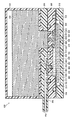
図17は、従来のマイクロポンプの一例として、マイクロポンプの全体の断面を示す図である。   FIG. 17 is a diagram showing an entire cross section of a micro pump as an example of a conventional micro pump.

図17に示すように、従来のマイクロポンプ900は、圧電素子923に交流電圧を印加することによって、圧電素子923に接着されてポンプ室920の底面を形成している振動板921を振動させ、ポンプ室920内の容積を変化させる。ポンプ室920は、ケース930の凹部内に形成され、吸入側逆止弁940を介して流体が吸入され、吐出側逆止弁950を介して流体が吐出される空間である。吸入側逆止弁940と、吐出側逆止弁950は、開いた傘のような形状である傘型弁である。吸入側逆止弁940の頭部941と吐出側逆止弁950の頭部951は扁平な形状であり、吸入側逆止弁940の脚部942と吐出側逆止弁950の脚部952は、球状に形成されて、ポンプ室920を構成するケース930から、それぞれの弁が抜け落ちないように支えている。吸入側逆止弁940の頭部941の頂部943と振動板921との間、吐出側逆止弁950の頭部951の頂部953と吐出管910を形成する壁面との間には、空間が設けられている。マイクロポンプ900の液タンク901内に貯留されている液体902は、振動板921の振動によってポンプ室920の容積が増大して、吸入側逆止弁940と吸入口931との間に隙間ができると、吸入口931を通ってポンプ室920の内部に流入する。また、ポンプ室920内に流入した液体は、振動板921の振動によってポンプ室920の容積が減少して、吐出側逆止弁950と吐出口932との間に隙間ができると、吐出口932を通ってポンプ室920の内部から吐出管910に流出し、吐出端911を通って外部に放出される。   As shown in FIG. 17, the conventional micropump 900 vibrates the diaphragm 921 that is bonded to the piezoelectric element 923 and forms the bottom surface of the pump chamber 920 by applying an alternating voltage to the piezoelectric element 923, The volume in the pump chamber 920 is changed. The pump chamber 920 is a space that is formed in the recess of the case 930, fluid is sucked in through the suction side check valve 940, and fluid is discharged through the discharge side check valve 950. The suction-side check valve 940 and the discharge-side check valve 950 are umbrella-shaped valves that are shaped like an open umbrella. A head portion 941 of the suction side check valve 940 and a head portion 951 of the discharge side check valve 950 have a flat shape, and a leg portion 942 of the suction side check valve 940 and a leg portion 952 of the discharge side check valve 950 are Each valve is supported so that it does not fall out from the case 930 which is formed in a spherical shape and constitutes the pump chamber 920. There is a space between the top 943 of the head 941 of the suction side check valve 940 and the diaphragm 921 and between the top 953 of the head 951 of the discharge side check valve 950 and the wall surface forming the discharge pipe 910. Is provided. The liquid 902 stored in the liquid tank 901 of the micro pump 900 increases the volume of the pump chamber 920 due to the vibration of the vibration plate 921, and a gap is formed between the suction side check valve 940 and the suction port 931. And flows into the pump chamber 920 through the suction port 931. Further, the liquid flowing into the pump chamber 920 is discharged when the volume of the pump chamber 920 is reduced by the vibration of the diaphragm 921 and a gap is formed between the discharge side check valve 950 and the discharge port 932. The liquid flows out from the inside of the pump chamber 920 to the discharge pipe 910, and is discharged to the outside through the discharge end 911.

しかしながら、マイクロポンプ900においては、傘型弁が穴を軽く塞いでいるのみであるため、圧電素子が振動を停止してポンプが駆動停止しているときに、吸入側から圧力が加われば、容易に液が出てしまう。   However, in the micropump 900, since the umbrella-type valve only blocks the hole lightly, it is easy to apply pressure from the suction side when the piezoelectric element stops vibration and the pump stops driving. Liquid will come out.

図18は、特開2000―274373号公報(特許文献1)に記載の小型ポンプの弁と、小型ポンプの全体の断面を示す図である。   FIG. 18 is a diagram illustrating a cross section of the small pump valve and the entire small pump described in Japanese Patent Laid-Open No. 2000-274373 (Patent Document 1).

図18(A)と(B)に示すように、特開2000―274373号公報(特許文献1)に記載の小型ポンプ901に用いられる吐出側逆止弁960(図18(B))と従来の逆止弁950(図18(A))は、どちらも開いた傘のような形状をしている傘型弁であるが、逆止弁960においては、傘部961の上面と軸部962とのなす角度αが、吸込側逆止弁940(図18(C))において傘部941と軸部942とのなす角度よりも小さく、傘部961の厚みが傘部941の厚みよりも大きい。このようにすることによって、傘型弁の底面において、軸側よりも周辺部が下がった形状にして、この傘型弁の周辺部分を弁座部分に押し付けるように構成されている。このようにして、弁を開くのに力が必要なようにして漏れを防止している。小型ポンプ901のその他の構成は、マイクロポンプ900と同様である。   As shown in FIGS. 18A and 18B, the discharge-side check valve 960 (FIG. 18B) used in the small pump 901 described in Japanese Patent Application Laid-Open No. 2000-274373 (Patent Document 1) and the related art. The check valve 950 (FIG. 18A) is an umbrella type valve that is shaped like an open umbrella. In the check valve 960, the upper surface of the umbrella portion 961 and the shaft portion 962 are used. Is smaller than the angle formed by the umbrella portion 941 and the shaft portion 942 in the suction side check valve 940 (FIG. 18C), and the thickness of the umbrella portion 961 is larger than the thickness of the umbrella portion 941. . In this manner, the bottom part of the umbrella-type valve is configured such that the peripheral part is lowered from the shaft side, and the peripheral part of the umbrella-type valve is pressed against the valve seat part. In this way, leakage is prevented by requiring a force to open the valve. Other configurations of the small pump 901 are the same as those of the micro pump 900.

図19は、特開2000−274374号公報(特許文献2)に記載の小型ポンプの断面を示す図である。   FIG. 19 is a view showing a cross section of a small pump described in Japanese Patent Laid-Open No. 2000-274374 (Patent Document 2).

図19に示すように、小型ポンプ902においては、吸入側逆止弁940と吐出側逆止弁960に加えて、吐出側逆止弁960よりも吐出端911側にさらに遮断弁970を備えることによって、漏れを防止している。小型ポンプ902のその他の構成は、マイクロポンプ900と同様である。
特開2000―274373号公報 特開2000−274374号公報
As shown in FIG. 19, in the small pump 902, in addition to the suction side check valve 940 and the discharge side check valve 960, a shutoff valve 970 is further provided on the discharge end 911 side of the discharge side check valve 960. Prevents leakage. Other configurations of the small pump 902 are the same as those of the micro pump 900.
JP 2000-274373 A JP 2000-274374 A

しかしながら、従来のマイクロポンプ900や、特開2000―274373号公報(特許文献1)と特開2000−274374号公報(特許文献2)の小型ポンプに用いられている傘型弁は、弁の頭部の反対側である脚部の先端を球状等にして穴にはめ込む形であるので、成型後、弁を金型から取り出すのが困難である。また、弁をポンプに取り付ける際に、丸い突起部を穴にはめ込むのに力が必要である。   However, the umbrella-type valve used in the conventional micropump 900 and the small pumps disclosed in JP 2000-274373 A (Patent Document 1) and JP 2000-274374 A (Patent Document 2) is the head of the valve. Since the tip of the leg, which is the opposite side of the part, has a spherical shape or the like and is fitted into the hole, it is difficult to remove the valve from the mold after molding. Also, when attaching the valve to the pump, a force is required to fit the round protrusion into the hole.

また、特開2000−274374号公報(特許文献2)に記載の小型ポンプでは、弁の数が増えることによって、構造が複雑化、大型化し、ポンプを組み立てにくくなったり、コストが上昇したりする等の課題がある。   Further, in the small pump described in Japanese Patent Application Laid-Open No. 2000-274374 (Patent Document 2), the number of valves increases, so that the structure becomes complicated and large, and it becomes difficult to assemble the pump or the cost increases. There are issues such as.

そこで、この発明の目的は、安価で組み立てやすく、駆動停止時の液漏れを防止することが可能なマイクロポンプを提供することである。   SUMMARY OF THE INVENTION An object of the present invention is to provide a micropump that is inexpensive and easy to assemble and can prevent liquid leakage when driving is stopped.

この発明に従ったマイクロポンプは、流路を形成する第一の壁部と、流路に液体を吐出する吐出口、および、流路に液体を吸入する吸入口の少なくとも一方の出入口を有する第二の壁部と、出入口を閉塞または開放可能に配置され、かつ、第一の壁部と第二の壁部との間に挟まれた弁体とを備え、第二の壁部の弁体側の面は、弁体の中央部側で凹み、弁体が弾性変形することによって、弁体の周辺部に密着するように形成されている。   A micropump according to the present invention has a first wall portion that forms a flow path, a discharge port that discharges liquid into the flow path, and at least one inlet / outlet of a suction port that sucks liquid into the flow path. A second wall portion and a valve body that is disposed so as to be able to close or open the entrance and that is sandwiched between the first wall portion and the second wall portion, the valve body side of the second wall portion This surface is formed so as to be in close contact with the peripheral portion of the valve body by being dented on the central portion side of the valve body and elastically deforming the valve body.

弁体が弾性変形することによって弁体の周辺部に第二の壁部の弁体側の面が密着するように、弁体を第一の壁部と第二の壁部とで挟んで配置することによって、弁体の遮蔽力を高くすることができる。   The valve body is disposed between the first wall portion and the second wall portion so that the valve body side surface of the second wall portion is in close contact with the peripheral portion of the valve body due to elastic deformation of the valve body. As a result, the shielding power of the valve body can be increased.

また、弁体を第一の壁部と第二の壁部とで挟んで配置することによって、弁体を保持するために従来設けられていた、弁体の先端の丸い突起が不要になり、例えば、先端の平らな弁や薄膜状の弁のような、作製しやすい弁体を用いることができる。   In addition, by arranging the valve body between the first wall portion and the second wall portion, the round protrusion at the tip of the valve body, which has been conventionally provided to hold the valve body, is unnecessary. For example, it is possible to use a valve body that is easy to manufacture, such as a flat valve or a thin film valve.

このようにすることにより、安価で組み立てやすく、駆動停止時の液漏れを防止することが可能なマイクロポンプを提供することができる。   By doing so, it is possible to provide a micropump that is inexpensive, easy to assemble, and can prevent liquid leakage when driving is stopped.

この発明に従ったマイクロポンプにおいては、第一の壁部に対向する第二の壁部が凹面を形成していることが好ましい。   In the micropump according to the present invention, it is preferable that the second wall portion facing the first wall portion forms a concave surface.

このようにすることにより、弁体の中央部側で凹んだ第二の壁部を作製しやすくなる。   By doing in this way, it becomes easy to produce the 2nd wall part recessed at the center part side of the valve body.

この発明に従ったマイクロポンプにおいては、第二の壁部の凹面は、球面状に形成されていることが好ましい。   In the micropump according to the present invention, the concave surface of the second wall portion is preferably formed in a spherical shape.

このようにすることにより、第二の壁部が弁体の周辺部に密着しやすくなる。   By doing in this way, it becomes easy to contact | adhere the 2nd wall part to the peripheral part of a valve body.

この発明に従ったマイクロポンプにおいては、第二の壁部の凹面は、すり鉢状に形成されていることが好ましい。   In the micropump according to the present invention, the concave surface of the second wall is preferably formed in a mortar shape.

このようにすることにより、第二の壁部に凹面を形成することが非常に容易になる。   By doing in this way, it becomes very easy to form a concave surface in the 2nd wall part.

この発明に従ったマイクロポンプにおいては、弁体は、第一の壁部に接触するための突起を有することが好ましい。   In the micropump according to the present invention, the valve body preferably has a protrusion for contacting the first wall portion.

このようにすることにより、弁体を第一の壁部と第二の壁部との間に容易に挟んで保持することができる。また、例えば第一の壁部が振動板である場合に、振動板の振動を妨げずに、弁体を弾性変形させることができる。   By doing so, the valve body can be easily held between the first wall portion and the second wall portion. For example, when the first wall portion is a diaphragm, the valve body can be elastically deformed without disturbing the vibration of the diaphragm.

この発明に従ったマイクロポンプにおいては、弁体は、薄膜状であることが好ましい。   In the micropump according to the present invention, the valve body is preferably a thin film.

このようにすることにより、金型を必要とせずに弁体を作製することができる。   By doing in this way, a valve body can be produced, without requiring a metal mold | die.

この発明に従ったマイクロポンプにおいては、弁体は、第一の壁部および/または第二の壁部と弁体との位置関係を決めるための位置決め部を有することが好ましい。   In the micropump according to the present invention, the valve body preferably has a first wall portion and / or a positioning portion for determining a positional relationship between the second wall portion and the valve body.

このようにすることにより、弁体の位置を容易に決めて固定することができる。   By doing in this way, the position of a valve body can be determined and fixed easily.

この発明に従ったマイクロポンプにおいては、第一の壁部は、第一の壁部と弁体との位置関係を決めるための位置決め部を有することが好ましい。   In the micropump according to the present invention, the first wall portion preferably has a positioning portion for determining the positional relationship between the first wall portion and the valve body.

このようにすることにより、弁体の位置を容易に決めて固定することができる。   By doing in this way, the position of a valve body can be determined and fixed easily.

この発明に従ったマイクロポンプにおいては、第二の壁部は、第二の壁部と弁体との位置関係を決めるための位置決め部を有することが好ましい。   In the micropump according to the present invention, it is preferable that the second wall portion has a positioning portion for determining the positional relationship between the second wall portion and the valve body.

このようにすることにより、弁体の位置を容易に決めて固定することができる。   By doing in this way, the position of a valve body can be determined and fixed easily.

この発明に従ったマイクロポンプにおいては、第一の壁部は、凸部を有し、弁体は、第一の壁部の凸部と第二の壁部との間に挟まれていることが好ましい。   In the micropump according to the present invention, the first wall portion has a convex portion, and the valve body is sandwiched between the convex portion of the first wall portion and the second wall portion. Is preferred.

このようにすることにより、弁体に突起が形成されていない場合にも、弁体を第一の壁部と第二の壁部との間に容易に挟んで保持することができる。   By doing in this way, even when the projection is not formed on the valve body, the valve body can be easily sandwiched and held between the first wall portion and the second wall portion.

以上のように、この発明によれば、安価で組み立てやすく、駆動停止時の液漏れを防止することが可能なマイクロポンプを提供することができる。   As described above, according to the present invention, it is possible to provide a micropump that is inexpensive, easy to assemble, and can prevent liquid leakage when driving is stopped.

以下、この発明の実施の形態を図面に基づいて説明する。   Hereinafter, embodiments of the present invention will be described with reference to the drawings.

(第1実施形態)
図1は、この発明の第1実施形態として、マイクロポンプの全体を示す断面図である。
(First embodiment)
FIG. 1 is a cross-sectional view showing an entire micro pump as a first embodiment of the present invention.

図1に示すように、マイクロポンプ100は、液タンク101と、流路としてのポンプ室110と、外部からポンプ室110に液体を吸入するための吸入口310と、吸入口310において液体の流れを調節するための弁体として吸入側逆止弁500と、ポンプ室110の内部からポンプ室110の外部の流路としての吐出管202に液体を吐出する吐出口320と、吐出口320において液体の流れを調節するための弁体として吐出側逆止弁600と、第一の壁部として、ポンプ室110の容積を変化させるための振動板210とを備え、吸入側逆止弁500は、頭部501に形成された突起として頂部503が振動板210に接触するようにポンプ室110に組み込まれている。   As shown in FIG. 1, the micropump 100 includes a liquid tank 101, a pump chamber 110 as a flow path, a suction port 310 for sucking liquid from the outside into the pump chamber 110, and a liquid flow in the suction port 310. A suction side check valve 500 as a valve body for adjusting the pressure, a discharge port 320 for discharging liquid from the inside of the pump chamber 110 to a discharge pipe 202 as a flow path outside the pump chamber 110, and liquid at the discharge port 320 The discharge side check valve 600 as a valve body for adjusting the flow of the gas, and the diaphragm 210 for changing the volume of the pump chamber 110 as the first wall portion, A top 503 is incorporated in the pump chamber 110 as a protrusion formed on the head 501 so as to come into contact with the diaphragm 210.

吸入側逆止弁500を介して液体が吸入され、吐出側逆止弁600を介して液体が吐出されるまでの空間がポンプ室110であり、吸入側逆止弁500と吐出側逆止弁600は、それぞれ、第二の壁部としてのハウジング300に形成された吸入側弁座330と吐出側弁座400に取り付けられている。ポンプ室110の底面は振動板210によって形成されている。振動板210の端部は、ハウジング300と振動板側ケース212との間に挿入されて固定されている。振動板210の下面には、圧電素子211が接着されている。圧電素子211の下部には、空間が設けられ、圧電素子211は上下に振動することができる。ハウジング300の上部には、吸入吐出側ケース200が取り付けられており、吸入吐出側ケース200の内部に吐出管202が形成されている。ハウジング300と吸入吐出側ケース200との間には8の字Oリング103が配置されて密閉され、ハウジング300と振動板側ケース212との間にはOリング104が配置されて密閉されている。   A space until the liquid is sucked through the suction-side check valve 500 and the liquid is discharged through the discharge-side check valve 600 is the pump chamber 110, and the suction-side check valve 500 and the discharge-side check valve Reference numerals 600 are respectively attached to a suction side valve seat 330 and a discharge side valve seat 400 formed in a housing 300 as a second wall portion. The bottom surface of the pump chamber 110 is formed by a diaphragm 210. An end portion of the diaphragm 210 is inserted and fixed between the housing 300 and the diaphragm side case 212. A piezoelectric element 211 is bonded to the lower surface of the vibration plate 210. A space is provided below the piezoelectric element 211, and the piezoelectric element 211 can vibrate up and down. A suction / discharge side case 200 is attached to an upper portion of the housing 300, and a discharge pipe 202 is formed inside the suction / discharge side case 200. An 8-shaped O-ring 103 is disposed and sealed between the housing 300 and the suction / discharge-side case 200, and an O-ring 104 is disposed and sealed between the housing 300 and the diaphragm-side case 212. .

吸入側逆止弁500と吐出側逆止弁600は、弁の軸を含む縦断面が、相対的に断面積が大きい頭部と相対的に断面積が小さい脚部を有し、開いた傘のような形状をしている。   The suction-side check valve 500 and the discharge-side check valve 600 have a longitudinal section including the valve shaft, a head having a relatively large cross-sectional area, and a leg portion having a relatively small cross-sectional area, and an open umbrella. It has a shape like

吸入側逆止弁500は、扁平な頭部501を下に向け、位置決め部として棒状の脚部502を上に向けて、脚部502がハウジング300に取り付けられていることによってポンプ室110に組み込まれている。脚部502は、先端がほぼ平らであり、ハウジング300に形成された吸入側弁座330の位置決め部として凹部332に受容されて保持されている。吸入側逆止弁500の頭部501の突起として頂部503は、頭部501から突出して形成された突起であり、振動板210に接している。   The suction-side check valve 500 is incorporated in the pump chamber 110 by attaching the flat portion 502 to the housing 300 with the flat head portion 501 facing downward and the rod-shaped leg portion 502 facing upward as a positioning portion. It is. The leg 502 has a substantially flat tip, and is received and held in the recess 332 as a positioning portion of the suction side valve seat 330 formed in the housing 300. A top portion 503 as a protrusion of the head portion 501 of the suction-side check valve 500 is a protrusion formed to protrude from the head portion 501, and is in contact with the diaphragm 210.

吐出側逆止弁600は、扁平な頭部601を上に向け、位置決め部として棒状の脚部602を下に向けて、脚部602がハウジング300に取り付けられていることによって、ポンプ室110に組み込まれている。脚部602は、先端がほぼ平らであり、ハウジング300に形成された吐出側弁座400の位置決め部として凹部402に受容されて保持されている。吐出側逆止弁600の頭部601は、頂部603が、吐出管202の壁部を形成する第一の壁部としての吸入吐出側ケース200の内壁に形成された凸部として突起201に接している。この実施の形態では、例えば、吸入側逆止弁500の直径は5mm、圧電素子211の長さは17mmとする。   The discharge-side check valve 600 has a flat head 601 facing upward, a rod-shaped leg 602 facing downward as a positioning part, and the leg 602 is attached to the housing 300, so that the pump chamber 110 It has been incorporated. The leg 602 has a substantially flat tip, and is received and held in the recess 402 as a positioning portion of the discharge side valve seat 400 formed in the housing 300. The head 601 of the discharge-side check valve 600 has a top 603 that contacts the protrusion 201 as a convex portion formed on the inner wall of the suction / discharge-side case 200 as a first wall that forms the wall of the discharge pipe 202. ing. In this embodiment, for example, the diameter of the suction side check valve 500 is 5 mm, and the length of the piezoelectric element 211 is 17 mm.

ポンプ室110の上部には、液タンク101が配置されており、液タンク101の内部には液体102が貯留されている。液タンク101の下部と吸入吐出側ケース200の上部は開口部105によって連結されており、液体102は開口部105を通って吸入口310に入る。   A liquid tank 101 is disposed in the upper part of the pump chamber 110, and the liquid 102 is stored inside the liquid tank 101. The lower part of the liquid tank 101 and the upper part of the suction / discharge-side case 200 are connected by the opening 105, and the liquid 102 enters the suction port 310 through the opening 105.

圧電素子211に交流電圧を印加することによって、交流電圧の周波数に対応する周波数で圧電素子211が振動する。この圧電素子211の振動と連動して、圧電素子211に接着されている振動板210が振動し、ポンプ室110の容積を変化させる。振動板210が上下どちらにも変位していないときには、吸入側逆止弁500の頭部501が吸入口310を閉じ、吐出側逆止弁600の頭部601が吐出口320を閉じている。   By applying an AC voltage to the piezoelectric element 211, the piezoelectric element 211 vibrates at a frequency corresponding to the frequency of the AC voltage. In conjunction with the vibration of the piezoelectric element 211, the vibration plate 210 bonded to the piezoelectric element 211 vibrates and changes the volume of the pump chamber 110. When the diaphragm 210 is not displaced vertically, the head 501 of the suction side check valve 500 closes the suction port 310, and the head 601 of the discharge side check valve 600 closes the discharge port 320.

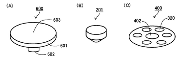
図2は、この発明の第1実施形態のマイクロポンプに用いられる吐出側逆止弁(A)と、突起(B)と、吐出側弁座の上面(C)を示す図である。   FIG. 2 is a view showing a discharge-side check valve (A), a protrusion (B), and an upper surface (C) of the discharge-side valve seat used in the micropump of the first embodiment of the present invention.

図2の(A)に示すように、吐出側逆止弁600は、扁平な頭部601と棒状の脚部602を有し、頂部603を含む頭部601の上面は平らである。   As shown in FIG. 2A, the discharge-side check valve 600 has a flat head 601 and a rod-like leg 602, and the upper surface of the head 601 including the top 603 is flat.

図2の(B)に示すように、吐出管202(図1)の壁部を形成する吸入吐出側ケース200(図1)の内壁に形成された突起201は、円柱状の部分と円錐台状の部分とを有し、円柱の下面と円錐台の上面を互いに接合した形状である。突起201の円錐台状の部分においては、円柱と接合している上面の径が相対的に大きく、下面の径が相対的に小さい。吐出側逆止弁600がマイクロポンプに組み込まれると、突起201の下面が吐出側逆止弁600の頂部603を押圧する。   As shown in FIG. 2B, the protrusion 201 formed on the inner wall of the suction / discharge-side case 200 (FIG. 1) that forms the wall of the discharge pipe 202 (FIG. 1) has a cylindrical portion and a truncated cone. The bottom surface of the cylinder and the top surface of the truncated cone are joined to each other. In the frustoconical portion of the protrusion 201, the diameter of the upper surface joined to the cylinder is relatively large and the diameter of the lower surface is relatively small. When the discharge side check valve 600 is incorporated in the micro pump, the lower surface of the protrusion 201 presses the top 603 of the discharge side check valve 600.

図2の(C)に示すように、吐出側弁座400には、吐出側逆止弁600の脚部602を受容するための凹部402と、凹部402を取り囲むようにして複数の吐出口320が形成されている。   As shown in FIG. 2C, the discharge-side valve seat 400 has a recess 402 for receiving the leg 602 of the discharge-side check valve 600, and a plurality of discharge ports 320 surrounding the recess 402. Is formed.

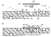
図3は、この発明の第1実施形態のマイクロポンプに用いられる吐出側逆止弁と吐出側逆止弁の周辺の断面を示す図である。図3の(A)は、吐出側逆止弁が吐出側弁座に挿入される前の状態を示し、図3の(B)は、吐出側逆止弁が吐出側弁座に挿入されてハウジングに組み込まれた状態を示す。   FIG. 3 is a view showing a cross section around the discharge-side check valve and the discharge-side check valve used in the micropump of the first embodiment of the present invention. 3A shows a state before the discharge-side check valve is inserted into the discharge-side valve seat, and FIG. 3B shows a state where the discharge-side check valve is inserted into the discharge-side valve seat. The state assembled in the housing is shown.

図3の(A)に示すように、吐出側逆止弁600は、扁平な頭部601と棒状の脚部602を有し、頂部603を含む頭部601の上面は平らである。吐出側弁座400は、ハウジング300内に形成されており、吐出側逆止弁600の脚部602を受容するための凹部402を有する。吐出側弁座400の上面には、吐出側逆止弁600の頭部601の下面が接するための凹面401が形成されている。凹面401は、吐出側逆止弁600の脚部602を受容するための凹部402側で凹んだすり鉢の内面のような傾斜に形成されている。   As shown in FIG. 3A, the discharge-side check valve 600 has a flat head 601 and a rod-like leg 602, and the upper surface of the head 601 including the top 603 is flat. The discharge side valve seat 400 is formed in the housing 300 and has a recess 402 for receiving the leg portion 602 of the discharge side check valve 600. A concave surface 401 is formed on the upper surface of the discharge-side valve seat 400 so that the lower surface of the head 601 of the discharge-side check valve 600 comes into contact therewith. The concave surface 401 is formed to have an inclination like the inner surface of a mortar recessed on the concave portion 402 side for receiving the leg portion 602 of the discharge side check valve 600.

図3の(B)に示すように、吐出側逆止弁600の脚部602が吐出側弁座400の凹部402に上方から挿入されて、吐出側逆止弁600が吐出側弁座400に組み込まれる。また、吐出管202(図1)の内壁に形成された突起201が、吐出側逆止弁600の頂部603を上方から押圧するようにして、吐出側逆止弁600を固定している。このようにすることにより、吐出側逆止弁600の頭部601が弾性変形し、頭部601においては、吐出側弁座400の上面に形成された凹面401に沿って、吐出管202の突起201側に凹面が形成され、吐出側弁座400側に脚部602を中心にして凸面が形成されて、頭部601の周辺部は、吐出側弁座400に密着する。   As shown in FIG. 3B, the leg portion 602 of the discharge side check valve 600 is inserted into the recess 402 of the discharge side valve seat 400 from above, and the discharge side check valve 600 is connected to the discharge side valve seat 400. Incorporated. Further, the protrusion 201 formed on the inner wall of the discharge pipe 202 (FIG. 1) fixes the discharge-side check valve 600 so that the top portion 603 of the discharge-side check valve 600 is pressed from above. By doing so, the head 601 of the discharge side check valve 600 is elastically deformed, and in the head 601, the protrusion of the discharge pipe 202 is formed along the concave surface 401 formed on the upper surface of the discharge side valve seat 400. A concave surface is formed on the 201 side, a convex surface is formed on the discharge side valve seat 400 side with the leg portion 602 as a center, and the peripheral portion of the head 601 is in close contact with the discharge side valve seat 400.

この実施形態のマイクロポンプ100においては、吸入側弁座330も吐出側弁座400と同様に、ハウジング300内に形成されており、吸入側逆止弁500の脚部502を受容するための凹部332を有する(図1)。吸入側弁座330の下面には、吸入側逆止弁500の頭部501の上面が接するための凹面331が形成されている。凹面331は、吸入側逆止弁500の脚部502を受容するための凹部332側で凹んだすり鉢の内面のような傾斜に形成されている。吸入側弁座330には、吸入側逆止弁500の脚部502を受容するための凹部332を取り囲むようにして複数の吸入口310が形成されている。また、吸入側逆止弁500は、扁平な頭部501と棒状の脚部502を有し、頭部501の上面の頂部503は突出した突起状に形成されている。吸入側逆止弁500の脚部502が吸入側弁座330の凹部332に下方から挿入されて、吸入側逆止弁500が吸入側弁座330に組み込まれる。また、振動板210が、吸入側逆止弁500の頂部503を下方から押圧するようにして、吸入側逆止弁500を固定している。このようにすることにより、吸入側逆止弁500の頭部501が弾性変形し、頭部501においては、吸入側弁座330の下面に形成された凹面331に沿って、振動板210側に頂部503を中心にして凹面が形成され、吸入側弁座330側に脚部502を中心にして凸面が形成されて、頭部501の周辺部は、吸入側弁座330に密着する。   In the micropump 100 of this embodiment, the suction side valve seat 330 is also formed in the housing 300 in the same manner as the discharge side valve seat 400, and is a recess for receiving the leg portion 502 of the suction side check valve 500. 332 (FIG. 1). A concave surface 331 is formed on the lower surface of the suction side valve seat 330 so that the upper surface of the head portion 501 of the suction side check valve 500 comes into contact therewith. The concave surface 331 is formed to be inclined like the inner surface of a mortar recessed on the concave portion 332 side for receiving the leg portion 502 of the suction side check valve 500. A plurality of suction ports 310 are formed in the suction side valve seat 330 so as to surround a recess 332 for receiving the leg portion 502 of the suction side check valve 500. The suction side check valve 500 has a flat head portion 501 and a rod-like leg portion 502, and the top portion 503 on the upper surface of the head portion 501 is formed in a protruding shape. The leg 502 of the suction side check valve 500 is inserted into the recess 332 of the suction side valve seat 330 from below, and the suction side check valve 500 is incorporated into the suction side valve seat 330. In addition, the diaphragm 210 fixes the suction side check valve 500 so as to press the top portion 503 of the suction side check valve 500 from below. By doing so, the head portion 501 of the suction side check valve 500 is elastically deformed, and the head portion 501 moves toward the diaphragm 210 along the concave surface 331 formed on the lower surface of the suction side valve seat 330. A concave surface is formed around the top portion 503, and a convex surface is formed around the leg portion 502 on the suction side valve seat 330 side, so that the peripheral portion of the head 501 is in close contact with the suction side valve seat 330.

図4は、この発明の一つの実施の形態として、振動板を振動させてポンプ室の容積を変化させたときのマイクロポンプの動作を順に示す図である。   FIG. 4 is a diagram sequentially illustrating the operation of the micropump when the diaphragm is vibrated and the volume of the pump chamber is changed as one embodiment of the present invention.

まず、図4(A)は、ポンプ室内に液体を吸入するときのマイクロポンプのポンプ室周辺を示す断面図である。   First, FIG. 4A is a cross-sectional view showing the periphery of the pump chamber of the micropump when liquid is sucked into the pump chamber.

図4(A)に示すように、振動板210が下方向に変位すると、ポンプ室110の容積が大きくなる。ポンプ室110の容積が大きくなると、吸入側逆止弁500の頭部501と吸入口310との間に隙間ができて、液タンク101に溜められている液体102(図1)がポンプ室110内に流入する。このとき、吐出側逆止弁600の頭部601によって吐出口320はふさがれており、ポンプ室110内に流入した液体が吐出口320から流出することはない。   As shown in FIG. 4A, when the diaphragm 210 is displaced downward, the volume of the pump chamber 110 increases. When the volume of the pump chamber 110 increases, a gap is formed between the head 501 of the suction side check valve 500 and the suction port 310, and the liquid 102 (FIG. 1) stored in the liquid tank 101 is pumped. Flows in. At this time, the discharge port 320 is blocked by the head 601 of the discharge side check valve 600, and the liquid that has flowed into the pump chamber 110 does not flow out of the discharge port 320.

次に、図4(B)は、ポンプ室内に吸入した液体を外部に吐出するときのマイクロポンプのポンプ室周辺を示す断面図である。   Next, FIG. 4B is a cross-sectional view showing the periphery of the pump chamber of the micro pump when the liquid sucked into the pump chamber is discharged to the outside.

図4(B)に示すように、振動板210が上方向に変位すると、ポンプ室110の容積が小さくなる。ポンプ室110の容積が小さくなると、吸入側逆止弁500の頭部501と吸入口310との間の隙間がふさがれて、液タンク101からポンプ室110には液体が流入しない。一方、吐出側逆止弁600と吐出口320との間に隙間ができて、ポンプ室110内の液体が吐出口320から吐出管202に流出し、吐出端203を通って外部に吐出される。   As shown in FIG. 4B, when the diaphragm 210 is displaced upward, the volume of the pump chamber 110 is reduced. When the volume of the pump chamber 110 is reduced, the gap between the head 501 of the suction side check valve 500 and the suction port 310 is blocked, so that no liquid flows from the liquid tank 101 into the pump chamber 110. On the other hand, a gap is formed between the discharge side check valve 600 and the discharge port 320, and the liquid in the pump chamber 110 flows out from the discharge port 320 to the discharge pipe 202 and is discharged to the outside through the discharge end 203. .

マイクロポンプ100は、図1に示すように振動板210の変位がない状態と、図4(A)に示すようにポンプ室110の容積を大きくする方向に振動板210が変位している状態と、図4(B)に示すようにポンプ室110の容積を小さくする方向に振動板210が変位している状態と、を繰り返すことによって、液タンク101内の液体102をポンプ室110内に吸入し、外部に吐出する。   The micropump 100 has a state in which the diaphragm 210 is not displaced as shown in FIG. 1, and a state in which the diaphragm 210 is displaced in the direction of increasing the volume of the pump chamber 110 as shown in FIG. As shown in FIG. 4B, the liquid 102 in the liquid tank 101 is sucked into the pump chamber 110 by repeating the state in which the diaphragm 210 is displaced in the direction of decreasing the volume of the pump chamber 110. And discharged to the outside.

このように、マイクロポンプ100は、ポンプ室110を形成する振動板210と、吐出管202を形成する吸入吐出側ケース200と、吐出管202に液体を吐出する吐出口320を有する吐出側弁座400、および、ポンプ室110に液体を吸入する吸入口310を有する吸入側弁座330と、吸入口310を閉塞または開放可能に配置され、かつ、振動板210と吸入側弁座330との間に挟まれた吸入側逆止弁500と、吐出口320を閉塞または開放可能に配置され、かつ、吸入吐出側ケース200と吐出側弁座400との間に挟まれた吐出側逆止弁600とを備え、吐出側弁座400の吐出側逆止弁600側の面は、吐出側逆止弁600の中央部側で凹み、吐出側逆止弁600が弾性変形することによって、吐出側逆止弁600の周辺部に密着するように形成されている。吸入側弁座330の吸入側逆止弁500側の面は、吸入側逆止弁500の中央部側で凹み、吸入側逆止弁500が弾性変形することによって、吸入側逆止弁500の周辺部に密着するように形成されている。   As described above, the micropump 100 includes a diaphragm 210 that forms the pump chamber 110, a suction / discharge-side case 200 that forms the discharge pipe 202, and a discharge-side valve seat that has the discharge port 320 that discharges liquid into the discharge pipe 202. 400 and a suction side valve seat 330 having a suction port 310 for sucking liquid into the pump chamber 110, and the suction port 310 can be closed or opened, and between the diaphragm 210 and the suction side valve seat 330. The suction side check valve 500 sandwiched between the suction side and the discharge side check valve 600 disposed between the suction / discharge side case 200 and the discharge side valve seat 400 and disposed so as to be able to close or open the discharge port 320. The surface on the discharge side check valve 600 side of the discharge side valve seat 400 is recessed on the center side of the discharge side check valve 600, and the discharge side check valve 600 is elastically deformed, whereby the discharge side reverse valve Stop valve 600 It is formed so as to be in close contact with the peripheral portion. The suction-side check valve 500 side surface of the suction-side valve seat 330 is recessed on the central side of the suction-side check valve 500, and the suction-side check valve 500 is elastically deformed. It is formed in close contact with the peripheral part.

吐出側逆止弁600が弾性変形することによって吐出側逆止弁600の周辺部に吐出側弁座400の吐出側逆止弁600側の面が密着するように、吐出側逆止弁600を吸入吐出側ケース200と吐出側弁座400とで挟んで配置することによって、吐出側逆止弁600の遮蔽力を高くすることができる。また、吸入側逆止弁500が弾性変形することによって吸入側逆止弁500の周辺部に吸入側弁座330の吸入側逆止弁500側の面が密着するように、吸入側逆止弁500を振動板210と吸入側弁座330とで挟んで配置することによって、吸入側逆止弁500の遮蔽力を高くすることができる。   The discharge side check valve 600 is elastically deformed so that the surface on the discharge side check valve 600 side of the discharge side valve seat 400 is in close contact with the periphery of the discharge side check valve 600. By disposing the suction and discharge side case 200 and the discharge side valve seat 400, the shielding force of the discharge side check valve 600 can be increased. In addition, the suction side check valve 500 is elastically deformed so that the surface of the suction side check valve 500 on the suction side check valve 500 side comes into close contact with the peripheral portion of the suction side check valve 500. By placing 500 between the vibration plate 210 and the suction side valve seat 330, the shielding force of the suction side check valve 500 can be increased.

また、吸入側逆止弁500を振動板210と吸入側弁座330とで挟んで配置し、吐出側逆止弁600を吸入吐出側ケース200と吐出側弁座400とで挟んで配置することによって、吸入側逆止弁500と吐出側逆止弁600を保持するために従来設けられていた、弁の先端の丸い突起(図17の吸入側逆止弁940の脚部942と吐出側逆止弁950の脚部952の先端の丸い突起)が不要になり、例えば、先端の平らな弁や薄膜状の弁のような、製作しやすい吸入側逆止弁500と吐出側逆止弁600を用いることができる。   Further, the suction side check valve 500 is disposed between the diaphragm 210 and the suction side valve seat 330, and the discharge side check valve 600 is disposed between the suction discharge side case 200 and the discharge side valve seat 400. Thus, a round protrusion at the tip of the valve (which is conventionally provided to hold the suction-side check valve 500 and the discharge-side check valve 600 (the leg 942 of the suction-side check valve 940 in FIG. 17 and the discharge-side reverse valve) is provided. For example, a suction-side check valve 500 and a discharge-side check valve 600 that are easy to manufacture, such as a flat valve or a thin-film valve, are not required. Can be used.

このようにすることにより、安価で組み立てやすく、駆動停止時の液漏れを防止することが可能なマイクロポンプ100を提供することができる。   By doing so, it is possible to provide a micropump 100 that is inexpensive and easy to assemble and can prevent liquid leakage when driving is stopped.

また、マイクロポンプ100においては、振動板210に対向する吸入側弁座330の下面が凹面331を形成し、吸入吐出側ケース200に対向する吐出側弁座400の上面が凹面401を形成している。   Further, in the micropump 100, the lower surface of the suction side valve seat 330 facing the diaphragm 210 forms a concave surface 331, and the upper surface of the discharge side valve seat 400 facing the suction / discharge side case 200 forms a concave surface 401. Yes.

このようにすることにより、吸入側逆止弁500の中央部側で凹んだ吸入側弁座330と、吐出側逆止弁600の中央部側で凹んだ吐出側弁座400を作製しやすくなる。   By doing so, it becomes easy to manufacture the suction side valve seat 330 that is recessed on the center side of the suction side check valve 500 and the discharge side valve seat 400 that is recessed on the center side of the discharge side check valve 600. .

また、吸入側弁座の凹面331と吐出側弁座の凹面401は、すり鉢状に形成されている。   The concave surface 331 of the suction side valve seat and the concave surface 401 of the discharge side valve seat are formed in a mortar shape.

このようにすることにより、吸入側弁座330と吐出側弁座400に、それぞれ凹面331と凹面401を形成することが非常に容易になる。なお、上記の実施の形態では吸入側弁座の凹面331と吐出側弁座の凹面401の両方がすり鉢状に形成されているが、吸入側弁座の凹面331と吐出側弁座の凹面401のいずれか一方のみがすり鉢状に形成されていてもよい。   By doing in this way, it becomes very easy to form the concave surface 331 and the concave surface 401 in the suction side valve seat 330 and the discharge side valve seat 400, respectively. In the above embodiment, both the concave surface 331 of the suction side valve seat and the concave surface 401 of the discharge side valve seat are formed in a mortar shape, but the concave surface 331 of the suction side valve seat and the concave surface 401 of the discharge side valve seat are formed. Only one of these may be formed in a mortar shape.

また、マイクロポンプ100においては、吸入側逆止弁500は、振動板210に接触するための頂部503を有する。   Further, in the micropump 100, the suction side check valve 500 has a top portion 503 for contacting the diaphragm 210.

このようにすることにより、振動板210の振動を妨げることなく、吸入側逆止弁500を弾性変形させることができる。   By doing so, the suction side check valve 500 can be elastically deformed without disturbing the vibration of the diaphragm 210.

また、マイクロポンプ100においては、吸入側逆止弁500は、吸入側弁座330と吸入側逆止弁500との位置関係を決めるための脚部502を有し、吸入側弁座330は、吸入側弁座330と吸入側逆止弁500との位置関係を決めるための凹部332を有し、吐出側逆止弁600は、吐出側弁座400と吐出側逆止弁600との位置関係を決めるための脚部602を有し、吐出側弁座400は、吐出側弁座400と吐出側逆止弁600との位置関係を決めるための凹部402を有する。   Further, in the micropump 100, the suction side check valve 500 has a leg portion 502 for determining the positional relationship between the suction side valve seat 330 and the suction side check valve 500. A recess 332 is provided for determining the positional relationship between the suction side valve seat 330 and the suction side check valve 500, and the discharge side check valve 600 is positioned between the discharge side valve seat 400 and the discharge side check valve 600. The discharge side valve seat 400 has a recess 402 for determining the positional relationship between the discharge side valve seat 400 and the discharge side check valve 600.

このようにすることにより、吸入側逆止弁500と吐出側逆止弁600の位置を容易に決めて固定することができる。   In this way, the positions of the suction-side check valve 500 and the discharge-side check valve 600 can be easily determined and fixed.

また、マイクロポンプ100においては、吸入吐出側ケース200は、突起201を有し、吐出側逆止弁600は、吸入吐出側ケース200の突起201と吐出側弁座400との間に挟まれている。   Further, in the micropump 100, the suction / discharge side case 200 has a protrusion 201, and the discharge side check valve 600 is sandwiched between the protrusion 201 of the suction / discharge side case 200 and the discharge side valve seat 400. Yes.

このようにすることにより、吐出側逆止弁600の頂部603に突起が形成されていない場合にも、吐出側逆止弁600を吸入吐出側ケース200と吐出側弁座400との間に容易に挟んで保持することができる。   In this way, even when no protrusion is formed on the top portion 603 of the discharge side check valve 600, the discharge side check valve 600 can be easily placed between the suction discharge side case 200 and the discharge side valve seat 400. Can be held between.

なお、遮蔽力の高い吸入側逆止弁500をマイクロポンプ100に用いる場合、マイクロポンプ100の駆動時に生じるポンプ室110の内部と外部との圧力差を大きくする必要がある。そこで、吸入側逆止弁500を振動板210と吸入側弁座330で挟んで配置することによって、ポンプ室110の容積を小さくして、マイクロポンプ100の駆動時に生じるポンプ室110の内部と外部との圧力差を大きくすることができる。従って、遮蔽力の高い吸入側逆止弁500でも吸入口310を開放することができるので、遮蔽力の高い吸入側逆止弁500をマイクロポンプ100に備えることができる。   When the suction-side check valve 500 having a high shielding power is used for the micropump 100, it is necessary to increase the pressure difference between the inside and the outside of the pump chamber 110 that is generated when the micropump 100 is driven. Therefore, by arranging the suction side check valve 500 between the diaphragm 210 and the suction side valve seat 330, the volume of the pump chamber 110 is reduced, and the inside and outside of the pump chamber 110 generated when the micropump 100 is driven. And the pressure difference can be increased. Therefore, since the suction port 310 can be opened even by the suction side check valve 500 having a high shielding power, the micro pump 100 can be provided with the suction side check valve 500 having a high shielding power.

(第2実施形態)
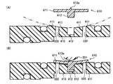
図5は、この発明の第2実施形態として、マイクロポンプに用いられる吐出側逆止弁と吐出側逆止弁の周辺の断面を示す図である。図5の(A)は、吐出側逆止弁が吐出側弁座に挿入される前の状態を示し、図5の(B)は、吐出側逆止弁が吐出側弁座に挿入されてハウジングに組み込まれた状態を示す。
(Second Embodiment)
FIG. 5 is a view showing a cross section around a discharge-side check valve and a discharge-side check valve used in a micropump as a second embodiment of the present invention. 5A shows a state before the discharge-side check valve is inserted into the discharge-side valve seat, and FIG. 5B shows a state where the discharge-side check valve is inserted into the discharge-side valve seat. The state assembled in the housing is shown.

図5の(A)に示すように、第2実施形態の吐出側逆止弁610は、第1実施形態の吐出側逆止弁600と同様に、扁平な頭部611と棒状の脚部612を有し、頂部613を含む頭部611の上面は平らである。吐出側弁座410は、吐出側逆止弁610の脚部612を受容するための凹部412を有する。吐出側弁座410の上面には、吐出側逆止弁610の頭部611の下面が接するための凹面411が形成されている。凹面411は、球の内面のような傾斜に形成されている。吐出側弁座410には、吐出側逆止弁610の脚部612を受容するための凹部412を取り囲むようにして複数の吐出口320が形成されている。   As shown in FIG. 5A, the discharge-side check valve 610 of the second embodiment has a flat head 611 and a rod-like leg 612, like the discharge-side check valve 600 of the first embodiment. The top surface of the head 611 including the top 613 is flat. The discharge side valve seat 410 has a recess 412 for receiving the leg portion 612 of the discharge side check valve 610. A concave surface 411 is formed on the upper surface of the discharge-side valve seat 410 so that the lower surface of the head 611 of the discharge-side check valve 610 comes into contact therewith. The concave surface 411 is formed with an inclination like the inner surface of a sphere. The discharge side valve seat 410 is formed with a plurality of discharge ports 320 so as to surround a recess 412 for receiving the leg portion 612 of the discharge side check valve 610.

図5の(B)に示すように、吐出側逆止弁610の脚部612が吐出側弁座410の凹部412に上方から挿入されて、吐出側逆止弁610が吐出側弁座410に組み込まれる。また、吐出管202(図1)の内壁に形成された突起201が、吐出側逆止弁610の頂部613を上方から押圧するようにして、吐出側逆止弁610を固定している。このようにすることにより、吐出側逆止弁610の頭部611が弾性変形し、頭部611においては吐出側弁座410の上面に形成された凹面411に沿って、吐出管202の内壁側に凹面が形成され、吐出側弁座410側に脚部612を中心にして凸面が形成されて、頭部611の周辺部が吐出側弁座410に密着する。   As shown in FIG. 5B, the leg portion 612 of the discharge side check valve 610 is inserted into the concave portion 412 of the discharge side valve seat 410 from above, and the discharge side check valve 610 is inserted into the discharge side valve seat 410. Incorporated. Further, the protrusion 201 formed on the inner wall of the discharge pipe 202 (FIG. 1) presses the top 613 of the discharge side check valve 610 from above to fix the discharge side check valve 610. By doing so, the head 611 of the discharge side check valve 610 is elastically deformed, and in the head 611, along the concave surface 411 formed on the upper surface of the discharge side valve seat 410, the inner wall side of the discharge pipe 202. A concave surface is formed on the discharge side valve seat 410, and a convex surface is formed on the discharge side valve seat 410 with the leg portion 612 as the center, and the periphery of the head 611 is in close contact with the discharge side valve seat 410.

このように、マイクロポンプ100においては、吸入吐出側ケース200に対向する吐出側弁座410が球面状の凹面411を形成している。このようにすることにより、吐出側弁座410が吐出側逆止弁610の周辺部に密着しやすくなる。   Thus, in the micropump 100, the discharge side valve seat 410 facing the suction / discharge side case 200 forms a spherical concave surface 411. By doing so, the discharge-side valve seat 410 can easily adhere to the peripheral portion of the discharge-side check valve 610.

吐出側逆止弁610は、図5の(B)に示すように、頭部611の下面が吐出側弁座410の凹面411に接するように、突起201に押圧されてもよい。また、吐出側逆止弁610の押さえ量を少なくして、吐出側逆止弁610の頭部611の下面の周辺部は吐出側弁座410に密着するが、頭部611の下面の全体が吐出側弁座410の凹面411に接しないように押圧されてもよい。   As shown in FIG. 5B, the discharge side check valve 610 may be pressed by the protrusion 201 so that the lower surface of the head 611 is in contact with the concave surface 411 of the discharge side valve seat 410. In addition, the pressing amount of the discharge side check valve 610 is reduced, and the peripheral portion of the lower surface of the head portion 611 of the discharge side check valve 610 is in close contact with the discharge side valve seat 410, but the entire lower surface of the head portion 611 is It may be pressed so as not to contact the concave surface 411 of the discharge side valve seat 410.

図6は、この発明の第2実施形態として、吐出側逆止弁の押さえ量が少ないときのマイクロポンプに用いられる吐出側逆止弁と吐出側逆止弁の周辺の断面を示す図である。図6の(A)は、吐出側逆止弁が吐出側弁座に挿入される前の状態を示し、図6の(B)は、吐出側逆止弁が吐出側弁座に挿入されてハウジングに組み込まれた状態を示す。   FIG. 6 is a view showing a cross section of the periphery of a discharge side check valve and a discharge side check valve used in a micropump when the amount of pressing of the discharge side check valve is small as a second embodiment of the present invention. . 6A shows the state before the discharge-side check valve is inserted into the discharge-side valve seat, and FIG. 6B shows the state where the discharge-side check valve is inserted into the discharge-side valve seat. The state assembled in the housing is shown.

図6の(A)に示すように、吐出側逆止弁610と吐出側弁座410は、それぞれ、図5の(A)に示す吐出側逆止弁610と吐出側弁座410と同様の形状である。   As shown in FIG. 6A, the discharge-side check valve 610 and the discharge-side valve seat 410 are the same as the discharge-side check valve 610 and the discharge-side valve seat 410 shown in FIG. Shape.

図6の(B)に示すように、吐出側逆止弁610の脚部612が吐出側弁座410の凹部412に上方から挿入されて、吐出側逆止弁610が吐出側弁座410に組み込まれる。また、吐出管202(図1)の内壁に形成された突起201が、吐出側逆止弁610の頂部613を上方から押圧するようにして、吐出側逆止弁610を固定している。突起201は、吐出側逆止弁610を押圧しているが、吐出側逆止弁610の下面において吐出側逆止弁610の中央部側は吐出側弁座410の凹面411には接していない。このようにすることにより、吐出側逆止弁610の頭部611が弾性変形し、頭部611においては、吐出管202の内壁側に凹面が形成され、吐出側弁座410側に脚部612を中心にして凸面が形成され、吐出側逆止弁610の頭部611の下面の周辺部は、吐出側弁座410の凹面411に密着している。   As shown in FIG. 6B, the leg portion 612 of the discharge side check valve 610 is inserted into the concave portion 412 of the discharge side valve seat 410 from above, and the discharge side check valve 610 is inserted into the discharge side valve seat 410. Incorporated. Further, the protrusion 201 formed on the inner wall of the discharge pipe 202 (FIG. 1) presses the top 613 of the discharge side check valve 610 from above to fix the discharge side check valve 610. The protrusion 201 presses the discharge side check valve 610, but the center side of the discharge side check valve 610 is not in contact with the concave surface 411 of the discharge side valve seat 410 on the lower surface of the discharge side check valve 610. . By doing so, the head 611 of the discharge-side check valve 610 is elastically deformed. In the head 611, a concave surface is formed on the inner wall side of the discharge pipe 202, and the leg 612 is formed on the discharge-side valve seat 410 side. And a peripheral portion of the lower surface of the head 611 of the discharge side check valve 610 is in close contact with the concave surface 411 of the discharge side valve seat 410.

このように、吐出側逆止弁610は、頭部611の周辺部が吐出側弁座410と密着していれば、中央部側の脚部612に近い部分では頭部611の下面が吐出側弁座410に接していなくてもよい。   As described above, the discharge side check valve 610 has a lower surface of the head 611 on the discharge side in a portion close to the leg 612 on the center side as long as the peripheral portion of the head 611 is in close contact with the discharge side valve seat 410. It does not have to be in contact with the valve seat 410.

第2実施形態のマイクロポンプのその他の構成と効果は、第1実施形態のマイクロポンプ100と同様である。   Other configurations and effects of the micro pump of the second embodiment are the same as those of the micro pump 100 of the first embodiment.

(第3実施形態)
図7は、この発明の第3実施形態として、マイクロポンプに用いられる吐出側逆止弁と吐出側逆止弁の周辺の断面を示す図である。図7の(A)は、吐出側逆止弁が吐出側弁座に挿入される前の状態を示し、図7の(B)は、吐出側逆止弁が吐出側弁座に挿入されてハウジングに組み込まれた状態を示す。
(Third embodiment)
FIG. 7 is a view showing a cross section around the discharge-side check valve and the discharge-side check valve used in the micropump as the third embodiment of the present invention. 7A shows a state before the discharge-side check valve is inserted into the discharge-side valve seat, and FIG. 7B shows a state where the discharge-side check valve is inserted into the discharge-side valve seat. The state assembled in the housing is shown.

図7の(A)に示すように、第3実施形態の吐出側逆止弁610は、扁平な頭部611と棒状の脚部612を有し、頭部611の上面は平らで、頭部611の中央部には、吸入吐出側ケース200の内壁に接触するための突起として突出した頂部613aを有する。   As shown in FIG. 7A, the discharge-side check valve 610 of the third embodiment has a flat head 611 and a rod-like leg 612, and the upper surface of the head 611 is flat. A central portion 611 has a top portion 613 a that protrudes as a protrusion for contacting the inner wall of the suction / discharge-side case 200.

図7の(B)に示すように、第3実施形態の吐出側弁座410は、ハウジング内に形成されており、吐出側逆止弁610の脚部612を受容するための凹部412を有する。吐出側弁座410の上面には、吐出側逆止弁610の頭部611の下面が接するための凹面411が形成されている。凹面411は、第2実施形態の吐出側弁座410と同様に、球面状に形成されている。吐出側弁座410には、吐出側逆止弁610の脚部612を受容するための凹部412を取り囲むようにして複数の吐出口320が形成されている。吐出管202の内壁に形成された突起201が、吐出側逆止弁610の頂部613aを上方から押圧するようにして、吐出側逆止弁610を固定している。突起201は、吐出側逆止弁610を押圧しているが、吐出側逆止弁610の下面において吐出側逆止弁610の中央部側は吐出側弁座410の凹面411には接していない。このようにすることにより、吐出側逆止弁610の頭部611が弾性変形し、頭部611においては、吐出管202の内壁側に凹面が形成され、吐出側弁座410側に脚部612を中心にして凸面が形成され、吐出側逆止弁610の頭部611の下面の周辺部は、吐出側弁座410の凹面411に密着している。   As shown in FIG. 7B, the discharge-side valve seat 410 of the third embodiment is formed in the housing and has a recess 412 for receiving the leg 612 of the discharge-side check valve 610. . A concave surface 411 is formed on the upper surface of the discharge-side valve seat 410 so that the lower surface of the head 611 of the discharge-side check valve 610 comes into contact therewith. The concave surface 411 is formed in a spherical shape like the discharge side valve seat 410 of the second embodiment. The discharge side valve seat 410 is formed with a plurality of discharge ports 320 so as to surround a recess 412 for receiving the leg portion 612 of the discharge side check valve 610. The protrusion 201 formed on the inner wall of the discharge pipe 202 presses the top portion 613a of the discharge side check valve 610 from above to fix the discharge side check valve 610. The protrusion 201 presses the discharge side check valve 610, but the center side of the discharge side check valve 610 is not in contact with the concave surface 411 of the discharge side valve seat 410 on the lower surface of the discharge side check valve 610. . By doing so, the head 611 of the discharge-side check valve 610 is elastically deformed. In the head 611, a concave surface is formed on the inner wall side of the discharge pipe 202, and the leg 612 is formed on the discharge-side valve seat 410 side. And a peripheral portion of the lower surface of the head 611 of the discharge side check valve 610 is in close contact with the concave surface 411 of the discharge side valve seat 410.

このように、吐出側逆止弁610は、頭部611の周辺部が吐出側弁座410と密着していれば、中央部側の脚部612に近い部分では頭部611の下面が吐出側弁座410に接していなくてもよい。   As described above, the discharge side check valve 610 has a lower surface of the head 611 on the discharge side in a portion close to the leg 612 on the center side as long as the peripheral portion of the head 611 is in close contact with the discharge side valve seat 410. It does not have to be in contact with the valve seat 410.

また、このように、第3実施形態のマイクロポンプにおいては、吐出側逆止弁610は、吐出管202の突起201に接触するための頂部613aを有する。   As described above, in the micro pump according to the third embodiment, the discharge-side check valve 610 has the top 613 a for contacting the protrusion 201 of the discharge pipe 202.

このようにすることにより、吐出側逆止弁610を突起201と吐出側弁座410との間に容易に挟んで保持することができる。   By doing so, the discharge-side check valve 610 can be easily sandwiched and held between the protrusion 201 and the discharge-side valve seat 410.

第3実施形態のマイクロポンプのその他の構成と効果は、第1実施形態のマイクロポンプ100と同様である。   Other configurations and effects of the micropump of the third embodiment are the same as those of the micropump 100 of the first embodiment.

(第4実施形態)
図8は、この発明の第4実施形態として、マイクロポンプに用いられる吐出側逆止弁と吐出側逆止弁の周辺の断面を示す図である。図8の(A)は、吐出側逆止弁が吐出側弁座に挿入される前の状態を示し、図8の(B)は、吐出側逆止弁が吐出側弁座に挿入されてハウジングに組み込まれた状態を示す。
(Fourth embodiment)
FIG. 8 is a view showing a cross section around the discharge-side check valve and the discharge-side check valve used in the micropump as the fourth embodiment of the present invention. 8A shows a state before the discharge-side check valve is inserted into the discharge-side valve seat, and FIG. 8B shows a state where the discharge-side check valve is inserted into the discharge-side valve seat. The state assembled in the housing is shown.

図8の(A)に示すように、第4実施形態の吐出側逆止弁620は、第1実施形態の吐出側逆止弁600と同様に、扁平な頭部621と棒状の脚部622を有し、頂部623を含む頭部621の上面は平らである。吐出側弁座420は、吐出側逆止弁620の脚部622を受容するための凹部422を有し、吐出側逆止弁620の脚部622を受容するための凹部422を取り囲むようにして複数の吐出口320が形成されている。また、吐出側弁座420には、吐出側逆止弁620の脚部622を受容するための凹部422を中心として、吐出口320の内側と外側との間に段差hが形成されて、吐出側弁座420が吐出側逆止弁620の中央部側で凹んでいる。   As shown in FIG. 8A, the discharge-side check valve 620 according to the fourth embodiment has a flat head 621 and a rod-like leg 622, similar to the discharge-side check valve 600 according to the first embodiment. The top surface of the head 621 including the top 623 is flat. The discharge-side valve seat 420 has a recess 422 for receiving the leg 622 of the discharge-side check valve 620 and surrounds the recess 422 for receiving the leg 622 of the discharge-side check valve 620. A plurality of discharge ports 320 are formed. Further, the discharge side valve seat 420 is formed with a step h between the inner side and the outer side of the discharge port 320 around the recess 422 for receiving the leg portion 622 of the discharge side check valve 620. The side valve seat 420 is recessed on the center side of the discharge side check valve 620.

図8の(B)に示すように、吐出側逆止弁620の脚部622が吐出側弁座420の凹部422に上方から挿入されて、吐出側逆止弁620が吐出側弁座420に組み込まれる。また、吐出管202(図1)の内壁に形成された突起201が、吐出側逆止弁620の頂部623を上方から押圧するようにして、吐出側逆止弁620を固定している。吐出側逆止弁620の頭部621は、吐出側弁座420の上面に形成された段差hによって、頭部621の周辺部が中央部よりも高くなる。このようにすることにより、吐出側逆止弁620の頭部621が弾性変形し、頭部621においては、吐出管202の内壁側に凹面が形成され、吐出側弁座420側に脚部622を中心にして凸面が形成されて、頭部621の周辺部が吐出側弁座420に密着する。   As shown in FIG. 8B, the leg 622 of the discharge-side check valve 620 is inserted into the recess 422 of the discharge-side valve seat 420 from above, and the discharge-side check valve 620 is inserted into the discharge-side valve seat 420. Incorporated. Further, the protrusion 201 formed on the inner wall of the discharge pipe 202 (FIG. 1) presses the top 623 of the discharge side check valve 620 from above to fix the discharge side check valve 620. In the head 621 of the discharge side check valve 620, the peripheral portion of the head 621 is higher than the central portion due to the step h formed on the upper surface of the discharge side valve seat 420. By doing so, the head 621 of the discharge side check valve 620 is elastically deformed, and in the head 621, a concave surface is formed on the inner wall side of the discharge pipe 202, and the leg portion 622 is formed on the discharge side valve seat 420 side. And a peripheral surface of the head 621 is in close contact with the discharge-side valve seat 420.

このようにすることにより、吐出側逆止弁620が弾性変形することによって吐出側逆止弁620の周辺部に吐出側弁座420の吐出側逆止弁620側の面が密着するように、吐出側逆止弁620を吸入吐出側ケース200と吐出側弁座420とで挟んで配置することによって、吐出側逆止弁620の遮蔽力を高くすることができる。   By doing in this way, the discharge side check valve 620 side surface of the discharge side check valve 420 is in close contact with the peripheral portion of the discharge side check valve 620 by the elastic deformation of the discharge side check valve 620. By disposing the discharge side check valve 620 between the suction discharge side case 200 and the discharge side valve seat 420, the shielding force of the discharge side check valve 620 can be increased.

また、吐出側逆止弁620を吸入吐出側ケース200と吐出側弁座420とで挟んで配置することによって、吐出側逆止弁620を保持するために従来設けられていた、弁の先端の丸い突起(図17の吐出側逆止弁950の脚部952の先端の丸い突起)が不要になり、例えば、先端の平らな弁や薄膜状の弁のような、製作しやすい吐出側逆止弁620を用いることができる。   In addition, by disposing the discharge side check valve 620 between the suction discharge side case 200 and the discharge side valve seat 420, the tip of the valve, which has been conventionally provided for holding the discharge side check valve 620, is provided. A round protrusion (a round protrusion at the tip of the leg 952 of the discharge-side check valve 950 in FIG. 17) is not necessary, and for example, a discharge-side check that is easy to manufacture, such as a flat valve at the tip or a thin-film valve. A valve 620 can be used.

このようにすることにより、安価で組み立てやすく、駆動停止時の液漏れを防止することが可能なマイクロポンプ100を提供することができる。   By doing so, it is possible to provide a micropump 100 that is inexpensive and easy to assemble and can prevent liquid leakage when driving is stopped.

第4実施形態のマイクロポンプのその他の構成と効果は、第1実施形態のマイクロポンプ100と同様である。   Other configurations and effects of the micropump of the fourth embodiment are the same as those of the micropump 100 of the first embodiment.

(第5実施形態)
図9は、この発明の第5実施形態として、マイクロポンプに用いられる吐出側逆止弁と吐出側逆止弁の周辺の断面を示す図である。図9の(A)は、吐出側逆止弁が吐出側弁座に挿入される前の状態を示し、図9の(B)は、吐出側逆止弁が吐出側弁座に挿入されてハウジングに組み込まれた状態を示す。
(Fifth embodiment)
FIG. 9 is a view showing a cross section around the discharge-side check valve and the discharge-side check valve used in the micropump as the fifth embodiment of the present invention. 9A shows a state before the discharge-side check valve is inserted into the discharge-side valve seat, and FIG. 9B shows a state where the discharge-side check valve is inserted into the discharge-side valve seat. The state assembled in the housing is shown.

図9の(A)に示すように、第5実施形態の吐出側逆止弁630は、第1実施形態の吐出側逆止弁600と同様に、扁平な頭部631と棒状の脚部632を有し、頂部633を含む頭部631の上面は平らである。吐出側弁座430は、吐出側逆止弁630の脚部632を受容するための凹部432を有し、吐出側逆止弁630の脚部632を受容するための凹部432を取り囲むようにして複数の吐出口320が形成されている。吐出側弁座430の上面には、吐出側逆止弁630の頭部631の周辺部の下面が接するための突起431が形成されている。言い換えれば、吐出側弁座430の上面は、突起431に対して吐出側逆止弁630の中央部側で凹んでいる。   As shown in FIG. 9A, the discharge-side check valve 630 of the fifth embodiment is similar to the discharge-side check valve 600 of the first embodiment in that it has a flat head 631 and a rod-like leg 632. The top surface of the head 631 including the top 633 is flat. The discharge side valve seat 430 has a recess 432 for receiving the leg portion 632 of the discharge side check valve 630 and surrounds the recess 432 for receiving the leg portion 632 of the discharge side check valve 630. A plurality of discharge ports 320 are formed. A protrusion 431 is formed on the upper surface of the discharge side valve seat 430 so that the lower surface of the peripheral portion of the head portion 631 of the discharge side check valve 630 comes into contact therewith. In other words, the upper surface of the discharge side valve seat 430 is recessed with respect to the protrusion 431 on the center side of the discharge side check valve 630.

図9の(B)に示すように、吐出側逆止弁630の脚部632が吐出側弁座430の凹部432に上方から挿入されて、吐出側逆止弁630が吐出側弁座430に組み込まれる。また、吐出管202(図1)の内壁に形成された突起201が、吐出側逆止弁630の頂部633を上方から押圧するようにして、吐出側逆止弁630を固定している。吐出側逆止弁630の頭部631は、吐出側弁座430の上面に形成された突起431によって、頭部631の周辺部が中央部よりも高くなる。このようにすることにより、吐出側逆止弁630の頭部631が弾性変形し、頭部631においては、吐出管202の内壁側に凹面が形成され、吐出側弁座430側に脚部632を中心にして凸面が形成されて、頭部631の周辺部が吐出側弁座430に密着する。   As shown in FIG. 9B, the leg portion 632 of the discharge side check valve 630 is inserted into the concave portion 432 of the discharge side valve seat 430 from above, and the discharge side check valve 630 is inserted into the discharge side valve seat 430. Incorporated. Further, the protrusion 201 formed on the inner wall of the discharge pipe 202 (FIG. 1) presses the top 633 of the discharge side check valve 630 from above to fix the discharge side check valve 630. In the head 631 of the discharge side check valve 630, the peripheral portion of the head 631 is higher than the center portion by the protrusion 431 formed on the upper surface of the discharge side valve seat 430. By doing so, the head portion 631 of the discharge side check valve 630 is elastically deformed. In the head portion 631, a concave surface is formed on the inner wall side of the discharge pipe 202, and the leg portion 632 on the discharge side valve seat 430 side. And a peripheral surface of the head 631 is in close contact with the discharge side valve seat 430.

このようにすることにより、吐出側逆止弁630が弾性変形することによって吐出側逆止弁630の周辺部に吐出側弁座430の吐出側逆止弁630側の面が密着するように、吐出側逆止弁630を吸入吐出側ケース200と吐出側弁座430とで挟んで配置することによって、吐出側逆止弁630の遮蔽力を高くすることができる。   By doing so, the discharge-side check valve 630 is elastically deformed so that the discharge-side check valve 630 side surface of the discharge-side check valve 430 is in close contact with the peripheral portion of the discharge-side check valve 630. By disposing the discharge side check valve 630 between the suction discharge side case 200 and the discharge side valve seat 430, the shielding force of the discharge side check valve 630 can be increased.

また、吐出側逆止弁630を吸入吐出側ケース200と吐出側弁座430とで挟んで配置することによって、吐出側逆止弁630を保持するために従来設けられていた、弁の先端の丸い突起(図17の吐出側逆止弁950の脚部952の先端の丸い突起)が不要になり、例えば、先端の平らな弁や薄膜状の弁のような、製作しやすい吐出側逆止弁630を用いることができる。   Further, by disposing the discharge-side check valve 630 between the suction-discharge-side case 200 and the discharge-side valve seat 430, the tip of the valve, which has been conventionally provided to hold the discharge-side check valve 630, is provided. A round protrusion (a round protrusion at the tip of the leg 952 of the discharge-side check valve 950 in FIG. 17) is not necessary, and for example, a discharge-side check that is easy to manufacture, such as a flat valve at the tip or a thin-film valve. A valve 630 can be used.

このようにすることにより、安価で組み立てやすく、駆動停止時の液漏れを防止することが可能なマイクロポンプ100を提供することができる。   By doing so, it is possible to provide a micropump 100 that is inexpensive and easy to assemble and can prevent liquid leakage when driving is stopped.

第5実施形態のマイクロポンプのその他の構成と効果は、第1実施形態のマイクロポンプ100と同様である。   Other configurations and effects of the micro pump of the fifth embodiment are the same as those of the micro pump 100 of the first embodiment.

(第6実施形態)
図10は、この発明の第6実施形態として、マイクロポンプに用いられる吐出側逆止弁と吐出側逆止弁の周辺の断面を示す図である。図10の(A)は、吐出側逆止弁の全体を示し、図10の(B)は、吐出側逆止弁が吐出側弁座に挿入されてハウジングに組み込まれた状態を示す。
(Sixth embodiment)
FIG. 10 is a view showing a cross section around the discharge-side check valve and the discharge-side check valve used in the micropump as the sixth embodiment of the present invention. 10A shows the entire discharge-side check valve, and FIG. 10B shows a state where the discharge-side check valve is inserted into the discharge-side valve seat and incorporated in the housing.

図10の(A)に示すように、第6実施形態の吐出側逆止弁640は、扁平な頭部641と棒状の脚部642を有し、頭部641の上面は平らで、頭部641の中央部には、吸入吐出側ケース200の内壁に接触するための突起として突出した頂部643を有する。   As shown in FIG. 10A, the discharge-side check valve 640 of the sixth embodiment has a flat head portion 641 and a rod-like leg portion 642, and the upper surface of the head portion 641 is flat. A central portion 641 has a top portion 643 protruding as a protrusion for contacting the inner wall of the suction / discharge-side case 200.

図10の(B)に示すように、第6実施形態の吐出側弁座440は、ハウジング内に形成されており、吐出側逆止弁640の脚部642を受容するための凹部442を有する。吐出側弁座440の上面には、吐出側逆止弁640の頭部641の下面が接するための凹面441が形成されている。凹面441は、第1実施形態の吐出側弁座400と同様に、すり鉢の内面のような傾斜に形成されている。吐出側弁座440には、吐出側逆止弁640の脚部642を受容するための凹部442を取り囲むようにして複数の吐出口320が形成されている。吐出管202の内壁に形成された突起201が、吐出側逆止弁640の頂部643を上方から押圧するようにして、吐出側逆止弁640を固定している。このようにすることにより、吐出側逆止弁640の頭部641が弾性変形し、頭部641においては、吐出側弁座440の上面に形成された凹面441に沿って、吐出管202の内壁側に頂部643を中心とした凹面が形成され、吐出側弁座440側に脚部642を中心とした凸面が形成されて、頭部641の周辺部が吐出側弁座440に密着する。   As shown in FIG. 10B, the discharge-side valve seat 440 of the sixth embodiment is formed in the housing and has a recess 442 for receiving the leg 642 of the discharge-side check valve 640. . A concave surface 441 is formed on the upper surface of the discharge side valve seat 440 so that the lower surface of the head portion 641 of the discharge side check valve 640 comes into contact therewith. The concave surface 441 is formed to be inclined like the inner surface of the mortar, similarly to the discharge side valve seat 400 of the first embodiment. A plurality of discharge ports 320 are formed in the discharge side valve seat 440 so as to surround the recesses 442 for receiving the leg portions 642 of the discharge side check valve 640. The protrusion 201 formed on the inner wall of the discharge pipe 202 presses the top portion 643 of the discharge side check valve 640 from above, thereby fixing the discharge side check valve 640. By doing so, the head portion 641 of the discharge side check valve 640 is elastically deformed, and the inner wall of the discharge pipe 202 is formed along the concave surface 441 formed on the upper surface of the discharge side valve seat 440 in the head portion 641. A concave surface centered on the top portion 643 is formed on the side, and a convex surface centered on the leg portion 642 is formed on the discharge side valve seat 440 side, and the peripheral portion of the head portion 641 is in close contact with the discharge side valve seat 440.

このように、第6実施形態のマイクロポンプにおいては、吐出側逆止弁640は、吐出管202の突起201に接触するための頂部643を有する。このようにすることにより、吐出側逆止弁640を吐出管202の内壁と吐出側弁座440との間に容易に挟んで保持することができる。   As described above, in the micro pump of the sixth embodiment, the discharge-side check valve 640 has the top 643 for contacting the protrusion 201 of the discharge pipe 202. In this way, the discharge check valve 640 can be easily held between the inner wall of the discharge pipe 202 and the discharge valve seat 440.

第6実施形態のマイクロポンプのその他の構成と効果は、第1実施形態のマイクロポンプ100と同様である。   Other configurations and effects of the micro pump of the sixth embodiment are the same as those of the micro pump 100 of the first embodiment.

(第7実施形態)
図11は、この発明の第7実施形態として、マイクロポンプに用いられる吐出側逆止弁と吐出側逆止弁の周辺の断面を示す図である。図11の(A)は、吐出側逆止弁の全体を示し、図11の(B)は、吐出側逆止弁がハウジングに組み込まれた状態を示す。
(Seventh embodiment)
FIG. 11 is a view showing a cross section around the discharge-side check valve and the discharge-side check valve used in the micropump as the seventh embodiment of the present invention. FIG. 11A shows the entire discharge-side check valve, and FIG. 11B shows a state where the discharge-side check valve is incorporated in the housing.

図11の(A)に示すように、第7実施形態の吐出側逆止弁650は、扁平な本体部651を有し、本体部651の上面は平らで、本体部651の中央部には突出した突起として頂部653を有する。吐出側逆止弁650は、脚部を有しない。   As shown in FIG. 11A, the discharge-side check valve 650 of the seventh embodiment has a flat main body 651, the upper surface of the main body 651 is flat, and the central portion of the main body 651 is A top portion 653 is provided as a protruding protrusion. The discharge side check valve 650 does not have a leg portion.

図11の(B)に示すように、第7実施形態の吐出側弁座450は、ハウジング内に形成されている。吐出側弁座450の上面には、吐出側逆止弁650の本体部651の下面が接するための凹面451が形成されている。凹面451は、第1実施形態の吐出側弁座400の凹面401と同様に、すり鉢の内面のような傾斜に形成されている。吐出側弁座450には、吐出側逆止弁650の中央部が接する部分を取り囲むようにして複数の吐出口320が形成されている。吐出管202の内壁に形成された突起201が、吐出側逆止弁650の頂部653を上方から押圧するようにして、吐出側逆止弁650を固定している。突起201の下端には、位置決め部として凹部205が形成されている。吐出側逆止弁650の頂部653は凹部205に嵌合して、吐出側逆止弁650と吸入吐出側ケース200との位置関係が決められる。このようにすることにより、吐出側逆止弁650の本体部651が弾性変形し、本体部651においては、吐出側弁座450の上面に形成された凹面451に沿って、吐出管202の内壁側に頂部653を中心として凹面が形成され、吐出側弁座450側に凸面が形成されて、本体部651の周辺部が吐出側弁座450に密着する。   As shown in FIG. 11B, the discharge side valve seat 450 of the seventh embodiment is formed in the housing. A concave surface 451 is formed on the upper surface of the discharge side valve seat 450 so that the lower surface of the main body 651 of the discharge side check valve 650 is in contact therewith. The concave surface 451 is formed to be inclined like the inner surface of the mortar, like the concave surface 401 of the discharge side valve seat 400 of the first embodiment. A plurality of discharge ports 320 are formed in the discharge side valve seat 450 so as to surround a portion where the central portion of the discharge side check valve 650 contacts. The protrusion 201 formed on the inner wall of the discharge pipe 202 presses the top portion 653 of the discharge side check valve 650 from above to fix the discharge side check valve 650. A recess 205 is formed at the lower end of the protrusion 201 as a positioning portion. The top portion 653 of the discharge side check valve 650 is fitted into the recess 205, and the positional relationship between the discharge side check valve 650 and the suction / discharge side case 200 is determined. By doing so, the main body portion 651 of the discharge side check valve 650 is elastically deformed, and in the main body portion 651, the inner wall of the discharge pipe 202 is formed along the concave surface 451 formed on the upper surface of the discharge side valve seat 450. A concave surface is formed around the top portion 653 on the side, a convex surface is formed on the discharge side valve seat 450 side, and the peripheral portion of the main body portion 651 is in close contact with the discharge side valve seat 450.

このように、第7実施形態のマイクロポンプにおいては、吐出側逆止弁650は、吐出管202の突起201に接触するための頂部653を有する。このようにすることにより、吐出側逆止弁650を吐出管202の内壁と吐出側弁座450との間に容易に挟んで保持することができる。   Thus, in the micropump of the seventh embodiment, the discharge side check valve 650 has the top portion 653 for contacting the protrusion 201 of the discharge pipe 202. In this way, the discharge side check valve 650 can be easily sandwiched and held between the inner wall of the discharge pipe 202 and the discharge side valve seat 450.

また、第7実施形態のマイクロポンプにおいては、吸入吐出側ケース200は、吸入吐出側ケース200と吐出側逆止弁650との位置関係を決めるための凹部205を有する。このようにすることにより、吐出側逆止弁650の位置を容易に決めて固定することができる。   In the micropump of the seventh embodiment, the suction / discharge side case 200 has a recess 205 for determining the positional relationship between the suction / discharge side case 200 and the discharge side check valve 650. In this way, the position of the discharge side check valve 650 can be easily determined and fixed.

第7実施形態のマイクロポンプのその他の構成と効果は、第1実施形態のマイクロポンプ100と同様である。   Other configurations and effects of the micro pump of the seventh embodiment are the same as those of the micro pump 100 of the first embodiment.

(第8実施形態)
図12は、この発明の第8実施形態として、マイクロポンプに用いられる吐出側逆止弁と吐出側逆止弁の周辺の断面を示す図である。図12の(A)は、吐出側逆止弁の全体を示し、図12の(B)は、吐出側逆止弁が吐出側弁座に挿入されてハウジングに組み込まれた状態を示す。
(Eighth embodiment)
FIG. 12 is a view showing a cross section around the discharge-side check valve and the discharge-side check valve used in the micropump as the eighth embodiment of the present invention. 12A shows the entire discharge-side check valve, and FIG. 12B shows a state where the discharge-side check valve is inserted into the discharge-side valve seat and incorporated in the housing.

図12の(A)に示すように、第8実施形態の吐出側逆止弁660は、扁平な頭部661と棒状の脚部662を有し、頭部661の上面は、中央部から周辺部に向かって降下する斜面を形成し、頭部661の中央部には突出した突起として頂部663を有する。このように、周辺部が薄い弁を用いることによって、遮蔽力を小さくすることができる。   As shown in FIG. 12A, the discharge-side check valve 660 of the eighth embodiment has a flat head portion 661 and a rod-like leg portion 662, and the upper surface of the head portion 661 extends from the center to the periphery. An inclined surface descending toward the part is formed, and a top part 663 is provided as a protruding protrusion at the center part of the head part 661. Thus, the shielding force can be reduced by using a valve having a thin peripheral portion.

図12の(B)に示すように、第8実施形態の吐出側弁座460は、ハウジング内に形成されており、吐出側逆止弁660の脚部662を受容するための凹部462を有する。吐出側弁座460の上面には、吐出側逆止弁660の頭部661の下面が接するための凹面461が形成されている。凹面461は、第1実施形態の吐出側弁座400と同様に、すり鉢の内面のような傾斜に形成されている。吐出側弁座460には、吐出側逆止弁660の脚部662を受容するための凹部462を取り囲むようにして複数の吐出口320が形成されている。吐出管202の内壁に形成された突起201が、吐出側逆止弁660の頂部663を上方から押圧するようにして、吐出側逆止弁660を固定している。このようにすることにより、吐出側逆止弁660の頭部661が弾性変形し、頭部661においては、吐出側弁座460の上面に形成された凹面461に沿って、吐出管202の内壁側に頂部663を中心にして凹面が形成され、吐出側弁座460側に脚部662を中心にして凸面が形成され、頭部661の周辺部が吐出側弁座460に密着する。   As shown in FIG. 12B, the discharge-side valve seat 460 of the eighth embodiment is formed in the housing and has a recess 462 for receiving the leg portion 662 of the discharge-side check valve 660. . A concave surface 461 is formed on the upper surface of the discharge-side valve seat 460 so that the lower surface of the head 661 of the discharge-side check valve 660 is in contact therewith. The concave surface 461 is formed to have an inclination like the inner surface of the mortar, similarly to the discharge side valve seat 400 of the first embodiment. The discharge-side valve seat 460 is formed with a plurality of discharge ports 320 so as to surround a recess 462 for receiving the leg portion 662 of the discharge-side check valve 660. The protrusion 201 formed on the inner wall of the discharge pipe 202 presses the top portion 663 of the discharge side check valve 660 from above to fix the discharge side check valve 660. By doing so, the head 661 of the discharge side check valve 660 is elastically deformed, and in the head 661, the inner wall of the discharge pipe 202 is formed along the concave surface 461 formed on the upper surface of the discharge side valve seat 460. A concave surface is formed around the top portion 663 on the side, a convex surface is formed around the leg portion 662 on the discharge side valve seat 460 side, and the peripheral portion of the head 661 is in close contact with the discharge side valve seat 460.

このように、第8実施形態のマイクロポンプにおいては、吐出側逆止弁660は、吐出管202の突起201に接触するための頂部663を有する。このようにすることにより、吐出側逆止弁660を吐出管202の内壁と吐出側弁座460との間に容易に挟んで保持することができる。   Thus, in the micropump of the eighth embodiment, the discharge-side check valve 660 has the top 663 for contacting the protrusion 201 of the discharge pipe 202. By doing so, the discharge-side check valve 660 can be easily held between the inner wall of the discharge pipe 202 and the discharge-side valve seat 460.

第8実施形態のマイクロポンプのその他の構成と効果は、第1実施形態のマイクロポンプ100と同様である。   Other configurations and effects of the micro pump of the eighth embodiment are the same as those of the micro pump 100 of the first embodiment.

(第9実施形態)
図13は、この発明の第9実施形態として、マイクロポンプに用いられる吐出側逆止弁と吐出側逆止弁の周辺の断面を示す図である。図13の(A)は、吐出側逆止弁の全体を示し、図13の(B)は、吐出側逆止弁がハウジングに組み込まれた状態を示す。
(Ninth embodiment)
FIG. 13 is a view showing a cross section around the discharge-side check valve and the discharge-side check valve used in the micropump as the ninth embodiment of the present invention. FIG. 13A shows the entire discharge-side check valve, and FIG. 13B shows a state where the discharge-side check valve is incorporated in the housing.

図13の(A)に示すように、第9実施形態の吐出側逆止弁670は、扁平な本体部671を有し、本体部671は平らな薄膜状としてゴムシートで形成されており、本体部671の中央部の下面には、位置決め部として凹部674を有する。   As shown in FIG. 13A, the discharge check valve 670 of the ninth embodiment has a flat main body 671, and the main body 671 is formed of a rubber sheet as a flat thin film. A concave portion 674 is provided as a positioning portion on the lower surface of the central portion of the main body portion 671.

図13の(B)に示すように、第9実施形態の吐出側弁座470は、ハウジング内に形成されており、吐出側逆止弁670の凹部674に嵌合するための位置決め部として凸部472を有する。吐出側弁座470の上面には、吐出側逆止弁670の本体部671の下面が接するための凹面471が凸部472を中心にして形成されている。凹面471は、第1実施形態の吐出側弁座400と同様に、すり鉢の内面のような傾斜に形成されている。吐出側弁座470には、吐出側逆止弁670の中央部が接する部分を取り囲むようにして複数の吐出口320が形成されている。吐出管202の内壁に形成された突起201が、吐出側逆止弁670の凹部674を上方から押圧するようにして、吐出側逆止弁670を固定している。このようにすることにより、吐出側逆止弁670の本体部671が弾性変形し、本体部671においては、吐出側弁座470の上面に形成された凹面471に沿って、吐出管202の内壁側に凹面が形成され、吐出側弁座470側に凹部674を中心にして凸面が形成され、本体部671の周辺部が吐出側弁座470に密着する。   As shown in FIG. 13B, the discharge-side valve seat 470 of the ninth embodiment is formed in the housing and protrudes as a positioning portion for fitting into the recess 674 of the discharge-side check valve 670. Part 472. On the upper surface of the discharge side valve seat 470, a concave surface 471 is formed with the convex portion 472 as the center so that the lower surface of the main body portion 671 of the discharge side check valve 670 comes into contact therewith. The concave surface 471 is formed with an inclination like the inner surface of the mortar, like the discharge-side valve seat 400 of the first embodiment. A plurality of discharge ports 320 are formed in the discharge side valve seat 470 so as to surround a portion where the central portion of the discharge side check valve 670 contacts. The protrusion 201 formed on the inner wall of the discharge pipe 202 presses the concave portion 674 of the discharge side check valve 670 from above to fix the discharge side check valve 670. By doing so, the main body portion 671 of the discharge side check valve 670 is elastically deformed, and in the main body portion 671, the inner wall of the discharge pipe 202 is formed along the concave surface 471 formed on the upper surface of the discharge side valve seat 470. A concave surface is formed on the side, a convex surface is formed around the concave portion 674 on the discharge side valve seat 470 side, and a peripheral portion of the main body portion 671 is in close contact with the discharge side valve seat 470.

このように、第9実施形態のマイクロポンプにおいては、吐出側逆止弁670は、薄膜状である。このようにすることにより、金型を必要とせずに吐出側逆止弁670を作製することができる。   Thus, in the micro pump of the ninth embodiment, the discharge-side check valve 670 is a thin film. By doing so, the discharge-side check valve 670 can be manufactured without the need for a mold.

また、第9実施形態のマイクロポンプにおいては、吐出側逆止弁670は、吐出側弁座470と吐出側逆止弁670との位置関係を決めるための凹部674を有する。このようにすることにより、吐出側逆止弁670の位置を容易に決めて固定することができる。   Further, in the micro pump of the ninth embodiment, the discharge side check valve 670 has a recess 674 for determining the positional relationship between the discharge side valve seat 470 and the discharge side check valve 670. In this way, the position of the discharge side check valve 670 can be easily determined and fixed.

また、第9実施形態のマイクロポンプにおいては、吐出側弁座470は、吐出側弁座470と吐出側逆止弁670との位置関係を決めるための凸部472を有する。   Further, in the micro pump of the ninth embodiment, the discharge side valve seat 470 has a convex part 472 for determining the positional relationship between the discharge side valve seat 470 and the discharge side check valve 670.

このようにすることにより、吐出側逆止弁670の位置を容易に決めて固定することができる。   In this way, the position of the discharge side check valve 670 can be easily determined and fixed.

第9実施形態のマイクロポンプのその他の構成と効果は、第1実施形態のマイクロポンプ100と同様である。   Other configurations and effects of the micro pump of the ninth embodiment are the same as those of the micro pump 100 of the first embodiment.

(第10実施形態)
図14は、この発明の第10実施形態として、マイクロポンプに用いられる吐出側逆止弁と吐出側逆止弁の周辺の断面を示す図である。図14の(A)は、吐出側逆止弁の全体を示し、図14の(B)は、吐出側逆止弁がハウジングに組み込まれた状態を示す。
(10th Embodiment)
FIG. 14 is a view showing a cross section around the discharge-side check valve and the discharge-side check valve used in the micropump as the tenth embodiment of the present invention. FIG. 14A shows the entire discharge-side check valve, and FIG. 14B shows a state where the discharge-side check valve is incorporated in the housing.

図14の(A)に示すように、第10実施形態の吐出側逆止弁680は、扁平な本体部681を有し、本体部681は平らな薄膜状としてゴムシートで形成されており、本体部681の中央部には、位置決め部として穴684を有する。   As shown in FIG. 14A, the discharge-side check valve 680 of the tenth embodiment has a flat main body portion 681, and the main body portion 681 is formed of a rubber sheet as a flat thin film, A central portion of the main body portion 681 has a hole 684 as a positioning portion.

図14の(B)に示すように、第10実施形態の吐出側弁座480は、ハウジング内に形成されており、吐出側弁座480の上面には、吐出側逆止弁680の本体部681の下面が接するための凹面481が形成されている。凹面481は、第1実施形態の吐出側弁座400と同様に、すり鉢の内面のような傾斜に形成されている。吐出側弁座480には、吐出側逆止弁680の中央部が接する部分を取り囲むようにして複数の吐出口320が形成されている。吐出管202の内壁に形成された突起201は、吐出側逆止弁680の穴684に嵌合するための位置決め部として凸部204を有する。突起201は、吐出側逆止弁680を上方から押圧するようにして、吐出側逆止弁680を固定している。このようにすることにより、吐出側逆止弁680の本体部681が弾性変形し、本体部681においては、吐出側弁座480の上面に形成された凹面481に沿って、吐出管202の内壁側に穴684を中心にして凹面が形成され、吐出側弁座480側に穴684を中心にして凸面が形成されて、本体部681の周辺部が吐出側弁座480に密着する。   As shown in FIG. 14B, the discharge side valve seat 480 of the tenth embodiment is formed in the housing, and the main body of the discharge side check valve 680 is formed on the upper surface of the discharge side valve seat 480. A concave surface 481 for contacting the lower surface of 681 is formed. The concave surface 481 is formed with an inclination like the inner surface of the mortar, like the discharge-side valve seat 400 of the first embodiment. A plurality of discharge ports 320 are formed in the discharge side valve seat 480 so as to surround a portion where the central portion of the discharge side check valve 680 contacts. The protrusion 201 formed on the inner wall of the discharge pipe 202 has a convex portion 204 as a positioning portion for fitting into the hole 684 of the discharge side check valve 680. The protrusion 201 fixes the discharge side check valve 680 so as to press the discharge side check valve 680 from above. By doing so, the main body portion 681 of the discharge side check valve 680 is elastically deformed. In the main body portion 681, the inner wall of the discharge pipe 202 is formed along the concave surface 481 formed on the upper surface of the discharge side valve seat 480. A concave surface is formed around the hole 684 on the side, a convex surface is formed around the hole 684 on the discharge side valve seat 480 side, and the peripheral portion of the main body portion 681 is in close contact with the discharge side valve seat 480.

このように、第10実施形態のマイクロポンプにおいては、吐出側逆止弁680は、薄膜状である。このようにすることにより、金型を必要とせずに吐出側逆止弁680を作製することができる。   Thus, in the micropump of the tenth embodiment, the discharge-side check valve 680 has a thin film shape. By doing so, the discharge-side check valve 680 can be manufactured without the need for a mold.

また、第10実施形態のマイクロポンプにおいては、吐出側逆止弁680は、吐出側弁座480と吐出側逆止弁680との位置関係を決めるための穴684を有する。このようにすることにより、吐出側逆止弁680の位置を容易に決めて固定することができる。   In the micropump of the tenth embodiment, the discharge side check valve 680 has a hole 684 for determining the positional relationship between the discharge side valve seat 480 and the discharge side check valve 680. In this way, the position of the discharge side check valve 680 can be easily determined and fixed.

また、第10実施形態のマイクロポンプにおいては、吸入吐出側ケース200は、吸入吐出側ケース200と吐出側逆止弁680との位置関係を決めるための凸部204を有する。このようにすることにより、吐出側逆止弁680の位置を容易に決めて固定することができる。   In the micropump of the tenth embodiment, the suction / discharge side case 200 has a convex portion 204 for determining the positional relationship between the suction / discharge side case 200 and the discharge side check valve 680. In this way, the position of the discharge side check valve 680 can be easily determined and fixed.

第10実施形態のマイクロポンプのその他の構成と効果は、第1実施形態のマイクロポンプ100と同様である。   Other configurations and effects of the micro pump of the tenth embodiment are the same as those of the micro pump 100 of the first embodiment.

(第11実施形態)
図15は、この発明の第11実施形態として、マイクロポンプに用いられる吐出側逆止弁と、吐出側弁座と、吐出側逆止弁の周辺の断面を示す図である。図15の(A)は、吐出側逆止弁の全体を示し、図15の(B)は、吐出側弁座の全体を示し、図15の(C)は、吐出側逆止弁がハウジングに組み込まれた状態を示す。
(Eleventh embodiment)
FIG. 15 is a view showing a cross section of the periphery of a discharge-side check valve, a discharge-side valve seat, and a discharge-side check valve used in a micropump as an eleventh embodiment of the present invention. 15A shows the whole discharge side check valve, FIG. 15B shows the whole discharge side valve seat, and FIG. 15C shows the discharge side check valve in the housing. The built-in state is shown.

図15の(A)に示すように、第11実施形態の吐出側逆止弁690は、平らな薄膜状としてゴムシートで形成されており、吐出側逆止弁690上には、突起や凹部、穴などが形成されていない。   As shown in FIG. 15A, the discharge-side check valve 690 of the eleventh embodiment is formed of a rubber sheet as a flat thin film, and a protrusion or a recess is formed on the discharge-side check valve 690. No holes are formed.

図15の(B)に示すように、第11実施形態の吐出側弁座490の上面には、吐出側逆止弁690の下面が接するための凹面491が形成されている。凹面491は、第1実施形態の吐出側弁座400と同様に、すり鉢の内面のような傾斜に形成されている。凹面491の中央部には、吐出側逆止弁690の位置決め手段として凸部494が形成されている。   As shown in FIG. 15B, a concave surface 491 for contacting the lower surface of the discharge side check valve 690 is formed on the upper surface of the discharge side valve seat 490 of the eleventh embodiment. The concave surface 491 is formed to have an inclination like the inner surface of the mortar, similarly to the discharge side valve seat 400 of the first embodiment. A convex portion 494 is formed in the central portion of the concave surface 491 as positioning means for the discharge side check valve 690.

図15の(C)に示すように、第11実施形態の吐出側弁座490は、ハウジング内に形成されており、吐出側弁座490には、吐出側逆止弁690の中央部を取り囲むようにして複数の吐出口320が形成されている。吐出管202の内壁に形成された突起201は、吐出側逆止弁690の位置を決めるための位置決め部として凸部204を下端に有する。突起201が、吐出側逆止弁690の頂部693を上方から押圧するようにして、吐出側逆止弁690を固定している。このようにすることにより、吐出側逆止弁690が弾性変形し、吐出側弁座490の上面に形成された凹面491に沿って、吐出管202の内壁側に凹面が形成され、吐出側弁座490側に凸面が形成されて、吐出側逆止弁690の周辺部が吐出側弁座490に密着する。   As shown in FIG. 15C, the discharge-side valve seat 490 of the eleventh embodiment is formed in the housing, and the discharge-side valve seat 490 surrounds the central portion of the discharge-side check valve 690. In this way, a plurality of discharge ports 320 are formed. The protrusion 201 formed on the inner wall of the discharge pipe 202 has a convex portion 204 at the lower end as a positioning portion for determining the position of the discharge side check valve 690. The protrusion 201 presses the top part 693 of the discharge side check valve 690 from above, and fixes the discharge side check valve 690. By doing so, the discharge side check valve 690 is elastically deformed, and a concave surface is formed on the inner wall side of the discharge pipe 202 along the concave surface 491 formed on the upper surface of the discharge side valve seat 490. A convex surface is formed on the seat 490 side, and the peripheral portion of the discharge side check valve 690 is in close contact with the discharge side valve seat 490.

このように、第11実施形態のマイクロポンプにおいては、吐出側逆止弁690は、薄膜状である。このようにすることにより、金型を必要とせずに吐出側逆止弁690を作製することができる。   Thus, in the micropump of the eleventh embodiment, the discharge-side check valve 690 is a thin film. By doing so, the discharge-side check valve 690 can be manufactured without the need for a mold.

また、第11実施形態のマイクロポンプにおいては、吐出側弁座490は、吐出側弁座490と吐出側逆止弁690との位置関係を決めるための凸部494を有する。このようにすることにより、吐出側逆止弁690の位置を容易に決めて固定することができる。   Further, in the micro pump of the eleventh embodiment, the discharge side valve seat 490 has a convex portion 494 for determining the positional relationship between the discharge side valve seat 490 and the discharge side check valve 690. In this way, the position of the discharge side check valve 690 can be easily determined and fixed.

また、第11実施形態のマイクロポンプにおいては、吸入吐出側ケース200は、吸入吐出側ケース200と吐出側逆止弁690との位置関係を決めるための凸部204を有する。このようにすることにより、吐出側逆止弁690の位置を容易に決めて固定することができる。   In the micropump of the eleventh embodiment, the suction / discharge side case 200 has a convex portion 204 for determining the positional relationship between the suction / discharge side case 200 and the discharge side check valve 690. In this way, the position of the discharge side check valve 690 can be easily determined and fixed.

第11実施形態のマイクロポンプのその他の構成と効果は、第1実施形態のマイクロポンプ100と同様である。   Other configurations and effects of the micro pump of the eleventh embodiment are the same as those of the micro pump 100 of the first embodiment.

(第12実施形態)
図16は、この発明の第12実施形態として、マイクロポンプに用いられる吐出側逆止弁(A)と、突起(B)と、吐出側弁座(C)と、吐出側逆止弁の周辺の断面(D)を示す図である。
(Twelfth embodiment)
FIG. 16 shows, as a twelfth embodiment of the present invention, a discharge side check valve (A), a protrusion (B), a discharge side valve seat (C), and a periphery of a discharge side check valve used in a micropump. It is a figure which shows the cross section (D).

図16の(A)に示すように、第12実施形態の吐出側逆止弁810は、薄膜状として長方形のシートで形成されている。   As shown in FIG. 16A, the discharge-side check valve 810 of the twelfth embodiment is formed of a rectangular sheet as a thin film.

図16の(B)に示すように、第12実施形態マイクロポンプは、吐出管の内壁に形成されて吐出側逆止弁810を押圧するための突起802を二つ有する。二つの突起802は、どちらも直方体の形状をしている。直方体状の突起802の下面が吐出側逆止弁810の上面を上から押圧する。   As shown in FIG. 16B, the twelfth embodiment micropump has two protrusions 802 that are formed on the inner wall of the discharge pipe to press the discharge-side check valve 810. Both of the two protrusions 802 have a rectangular parallelepiped shape. The lower surface of the rectangular parallelepiped protrusion 802 presses the upper surface of the discharge-side check valve 810 from above.

図16の(C)と(D)に示すように、第12実施形態の吐出側弁座820は、ハウジング内に形成されている。吐出側弁座820の上面には、吐出側逆止弁810の下面が接するための凹面822が形成されている。吐出側弁座820には、吐出側逆止弁810が載せられたときに吐出側逆止弁810の中央部の下に当たる部分に、一つの吐出口821が形成されている。吸入吐出側ケース801内の吐出管の内壁に形成された突起802が、吐出側逆止弁810の中央部より端部側を上方から押圧するようにして、吐出側逆止弁810を固定する。このようにすることにより、吐出側逆止弁810が弾性変形し、吐出側弁座820の上面に形成された凹面822に沿って、吐出管の内壁側に凹面が形成され、吐出側弁座820側に凸面が形成されて、吐出側逆止弁810の周辺部が吐出側弁座820に密着する。   As shown in FIGS. 16C and 16D, the discharge-side valve seat 820 of the twelfth embodiment is formed in the housing. A concave surface 822 is formed on the upper surface of the discharge side valve seat 820 so that the lower surface of the discharge side check valve 810 comes into contact therewith. The discharge side valve seat 820 is formed with one discharge port 821 at a portion of the discharge side check seat 820 that contacts the lower part of the center of the discharge side check valve 810 when the discharge side check valve 810 is placed. The protrusion 802 formed on the inner wall of the discharge pipe in the suction / discharge-side case 801 fixes the discharge-side check valve 810 so that the end side is pressed from above the central portion of the discharge-side check valve 810. . By doing so, the discharge-side check valve 810 is elastically deformed, and a concave surface is formed on the inner wall side of the discharge pipe along the concave surface 822 formed on the upper surface of the discharge-side valve seat 820. A convex surface is formed on the 820 side, and the periphery of the discharge-side check valve 810 is in close contact with the discharge-side valve seat 820.

第12実施形態のマイクロポンプのその他の構成と効果は、第1実施形態のマイクロポンプ100と同様である。   Other configurations and effects of the micropump of the twelfth embodiment are the same as those of the micropump 100 of the first embodiment.

以上に開示された実施の形態はすべての点で例示であって制限的なものではないと考慮されるべきである。本発明の範囲は、以上の実施の形態ではなく、特許請求の範囲によって示され、特許請求の範囲と均等の意味および範囲内でのすべての修正と変形を含むものである。   The embodiment disclosed above should be considered as illustrative in all points and not restrictive. The scope of the present invention is shown not by the above embodiments but by the scope of claims, and includes all modifications and variations within the meaning and scope equivalent to the scope of claims.

本発明の第一の実施の形態として、マイクロポンプの全体を示す断面図である。1 is a cross-sectional view showing an entire micro pump as a first embodiment of the present invention. この発明の第1実施形態のマイクロポンプに用いられる吐出側逆止弁(A)と、突起(B)と、吐出側弁座の上面(C)を示す図である。It is a figure which shows the upper surface (C) of the discharge side non-return valve (A), protrusion (B), and discharge side valve seat which are used for the micropump of 1st Embodiment of this invention. この発明の第1実施形態のマイクロポンプに用いられる吐出側逆止弁と吐出側逆止弁の周辺の断面を示す図である。It is a figure which shows the cross section of the periphery of the discharge side check valve used for the micro pump of 1st Embodiment of this invention, and a discharge side check valve. ポンプ室内に液体を吸入するときのマイクロポンプのポンプ室周辺を示す断面図(A)と、ポンプ室内に吸入した液体を外部に吐出するときのマイクロポンプのポンプ室周辺を示す断面図(B)である。Sectional view (A) showing the periphery of the pump chamber of the micropump when the liquid is sucked into the pump chamber, and sectional view (B) showing the periphery of the pump chamber of the micropump when the liquid sucked into the pump chamber is discharged to the outside It is. この発明の第2実施形態として、マイクロポンプに用いられる吐出側逆止弁と吐出側逆止弁の周辺の断面を示す図である。It is a figure which shows the cross section of the periphery of the discharge side check valve used for a micropump, and a discharge side check valve as 2nd Embodiment of this invention. この発明の第2実施形態として、吐出側逆止弁の押さえ量が少ないときのマイクロポンプに用いられる吐出側逆止弁と吐出側逆止弁の周辺の断面を示す図である。It is a figure which shows the cross section of the circumference | surroundings of the discharge side check valve used for a micropump when the pressing amount of a discharge side check valve is small as 2nd Embodiment of this invention, and a discharge side check valve. この発明の第3実施形態として、マイクロポンプに用いられる吐出側逆止弁と吐出側逆止弁の周辺の断面を示す図である。It is a figure which shows the cross section of the periphery of the discharge side check valve used for a micro pump, and a discharge side check valve as 3rd Embodiment of this invention. この発明の第4実施形態として、マイクロポンプに用いられる吐出側逆止弁と吐出側逆止弁の周辺の断面を示す図である。It is a figure which shows the cross section of the periphery of the discharge side check valve used for a micro pump, and a discharge side check valve as 4th Embodiment of this invention. この発明の第5実施形態として、マイクロポンプに用いられる吐出側逆止弁と吐出側逆止弁の周辺の断面を示す図である。It is a figure which shows the cross section of the circumference | surroundings of the discharge side check valve used for a micro pump, and a discharge side check valve as 5th Embodiment of this invention. この発明の第6実施形態として、マイクロポンプに用いられる吐出側逆止弁と吐出側逆止弁の周辺の断面を示す図である。It is a figure which shows the cross section of the periphery of the discharge side check valve and discharge side check valve which are used for a micro pump as 6th Embodiment of this invention. この発明の第7実施形態として、マイクロポンプに用いられる吐出側逆止弁と吐出側逆止弁の周辺の断面を示す図である。It is a figure which shows the cross section of the periphery of the discharge side check valve used for a micro pump, and a discharge side check valve as 7th Embodiment of this invention. この発明の第8実施形態として、マイクロポンプに用いられる吐出側逆止弁と吐出側逆止弁の周辺の断面を示す図である。It is a figure which shows the cross section of the periphery of the discharge side check valve used for a micro pump, and a discharge side check valve as 8th Embodiment of this invention. この発明の第9実施形態として、マイクロポンプに用いられる吐出側逆止弁と吐出側逆止弁の周辺の断面を示す図である。It is a figure which shows the cross section of the periphery of the discharge side check valve used for a micro pump, and a discharge side check valve as 9th Embodiment of this invention. この発明の第10実施形態として、マイクロポンプに用いられる吐出側逆止弁と吐出側逆止弁の周辺の断面を示す図である。It is a figure which shows the cross section of the periphery of the discharge side check valve used for a micropump, and a discharge side check valve as 10th Embodiment of this invention. この発明の第11実施形態として、マイクロポンプに用いられる吐出側逆止弁と、吐出側弁座と、吐出側逆止弁の周辺の断面を示す図である。It is a figure which shows the cross section of the circumference | surroundings of the discharge side check valve used for a micropump, a discharge side valve seat, and a discharge side check valve as 11th Embodiment of this invention. この発明の第12実施形態として、マイクロポンプに用いられる吐出側逆止弁(A)と、突起(B)と、吐出側弁座(C)と、吐出側逆止弁の周辺の断面(D)を示す図である。As a twelfth embodiment of the present invention, a discharge side check valve (A), a projection (B), a discharge side valve seat (C), and a cross section around the discharge side check valve (D) used in a micropump ). 従来のマイクロポンプの一例として、マイクロポンプの全体の断面を示す図である。It is a figure which shows the whole cross section of a micro pump as an example of the conventional micro pump. 従来の小型ポンプの弁と、小型ポンプの全体の断面を示す図である。It is a figure which shows the cross section of the valve of the conventional small pump, and the whole small pump. 従来の小型ポンプの全体の断面を示す図である。It is a figure which shows the whole cross section of the conventional small pump.

符号の説明Explanation of symbols

100,800:マイクロポンプ、110:ポンプ室、200,801:吸入吐出側ケース、201:突起、202:吐出管、204,494:凸部、205:凹部、210:振動板、300:ハウジング、310:吸入口、320:吐出口、330:吸入側弁座、331:凹面、400,410,420,430,440,450,460,470,480,490,820:吐出側弁座、401,411,441,451,461,471,481,491,822:凹面、500:吸入側逆止弁、600,610,620,630,640,650,660,670,680,690,810:吐出側逆止弁、333,613a,643,653,663:頂部、674:凹部、684:穴。
100, 800: Micro pump, 110: Pump chamber, 200, 801: Suction / discharge side case, 201: Protrusion, 202: Discharge pipe, 204, 494: Convex part, 205: Concavity, 210: Diaphragm, 300: Housing, 310: suction port, 320: discharge port, 330: suction side valve seat, 331: concave surface, 400, 410, 420, 430, 440, 450, 460, 470, 480, 490, 820: discharge side valve seat, 401, 411, 441, 451, 461, 471, 481, 491, 822: concave surface, 500: suction side check valve, 600, 610, 620, 630, 640, 650, 660, 670, 680, 690, 810: discharge side Check valve, 333, 613a, 643, 653, 663: top, 674: recess, 684: hole.

Claims (10)

流路を形成する第一の壁部と、
前記流路に液体を吐出する吐出口、および、流路に液体を吸入する吸入口の少なくとも一方の出入口を有する第二の壁部と、
前記出入口を閉塞または開放可能に配置され、かつ、前記第一の壁部と前記第二の壁部との間に挟まれた弁体とを備え、
前記第二の壁部の前記弁体側の面は、前記弁体の中央部側で凹み、前記弁体が弾性変形することによって、前記弁体の周辺部に密着するように形成されている、マイクロポンプ。
A first wall forming a flow path;
A discharge port for discharging liquid into the flow path; and a second wall portion having at least one inlet / outlet of a suction port for sucking liquid into the flow path;
A valve body disposed so as to be capable of closing or opening the entrance and being sandwiched between the first wall portion and the second wall portion;
The surface on the valve body side of the second wall is recessed on the center side of the valve body, and is formed so as to be in close contact with the peripheral portion of the valve body by elastically deforming the valve body. Micro pump.
前記第一の壁部に対向する前記第二の壁部が凹面を形成している、請求項1に記載のマイクロポンプ。   The micropump according to claim 1, wherein the second wall portion facing the first wall portion forms a concave surface. 前記第二の壁部の凹面は、球面状に形成されている、請求項2に記載のマイクロポンプ。   The micropump according to claim 2, wherein the concave surface of the second wall portion is formed in a spherical shape. 前記第二の壁部の凹面は、すり鉢状に形成されている、請求項2に記載のマイクロポンプ。   The micropump according to claim 2, wherein the concave surface of the second wall portion is formed in a mortar shape. 前記弁体は、前記第一の壁部に接触するための突起を有する、請求項1から請求項4までのいずれか1項に記載のマイクロポンプ。   The micro pump according to any one of claims 1 to 4, wherein the valve body has a protrusion for contacting the first wall portion. 前記弁体は、薄膜状である、請求項1から請求項5までのいずれか1項に記載のマイクロポンプ。   The micro pump according to any one of claims 1 to 5, wherein the valve body is in a thin film shape. 前記弁体は、前記第一の壁部および/または前記第二の壁部と前記弁体との位置関係を決めるための位置決め部を有する、請求項1から請求項6までのいずれか1項に記載のマイクロポンプ。   The said valve body has a positioning part for determining the positional relationship of said 1st wall part and / or said 2nd wall part, and said valve body, The any one of Claim 1-6 A micropump as described in 1. 前記第一の壁部は、前記第一の壁部と前記弁体との位置関係を決めるための位置決め部を有する、請求項1から請求項7までのいずれか1項に記載のマイクロポンプ。   The micro pump according to any one of claims 1 to 7, wherein the first wall portion includes a positioning portion for determining a positional relationship between the first wall portion and the valve body. 前記第二の壁部は、前記第二の壁部と前記弁体との位置関係を決めるための位置決め部を有する、請求項1から請求項8までのいずれか1項に記載のマイクロポンプ。   The micro pump according to any one of claims 1 to 8, wherein the second wall portion includes a positioning portion for determining a positional relationship between the second wall portion and the valve body. 前記第一の壁部は、凸部を有し、前記弁体は、前記第一の壁部の前記凸部と前記第二の壁部との間に挟まれている、請求項1から請求項9までのいずれか1項に記載のマイクロポンプ。   The said 1st wall part has a convex part, The said valve body is pinched | interposed between the said convex part and said 2nd wall part of a said 1st wall part. Item 10. The micropump according to any one of Items 9 to 9.
JP2007014872A 2007-01-25 2007-01-25 Micro pump Pending JP2008180171A (en)

Priority Applications (1)

Application Number Priority Date Filing Date Title
JP2007014872A JP2008180171A (en) 2007-01-25 2007-01-25 Micro pump

Applications Claiming Priority (1)

Application Number Priority Date Filing Date Title
JP2007014872A JP2008180171A (en) 2007-01-25 2007-01-25 Micro pump

Publications (2)

Publication Number Publication Date
JP2008180171A true JP2008180171A (en) 2008-08-07
JP2008180171A5 JP2008180171A5 (en) 2009-05-14

Family

ID=39724252

Family Applications (1)

Application Number Title Priority Date Filing Date
JP2007014872A Pending JP2008180171A (en) 2007-01-25 2007-01-25 Micro pump

Country Status (1)

Country Link
JP (1) JP2008180171A (en)

Cited By (3)

* Cited by examiner, † Cited by third party
Publication number Priority date Publication date Assignee Title
JP2010077912A (en) * 2008-09-26 2010-04-08 Kyoto Refre Shinyaku Kk Pump
JP2010112326A (en) * 2008-11-10 2010-05-20 Sharp Corp Micropump
EP3660309A1 (en) * 2018-11-30 2020-06-03 Okenseiko Co., Ltd. Diaphragm pump

Citations (6)

* Cited by examiner, † Cited by third party
Publication number Priority date Publication date Assignee Title
JPS5261543U (en) * 1975-11-01 1977-05-06
JPH06272665A (en) * 1992-01-15 1994-09-27 Knf Neuberger Gmbh Pump with valve capable of being controlled by carrying medium
JP2003028328A (en) * 2001-07-17 2003-01-29 Yushin Giken Kk Check valve
JP2003139258A (en) * 2001-11-06 2003-05-14 Oken Ltd Non-return valve
JP2005172206A (en) * 2003-12-15 2005-06-30 Alps Electric Co Ltd Check valve
JP2007010124A (en) * 2005-07-04 2007-01-18 Ookisu Medical:Kk Valve arrangement

Patent Citations (6)

* Cited by examiner, † Cited by third party
Publication number Priority date Publication date Assignee Title
JPS5261543U (en) * 1975-11-01 1977-05-06
JPH06272665A (en) * 1992-01-15 1994-09-27 Knf Neuberger Gmbh Pump with valve capable of being controlled by carrying medium
JP2003028328A (en) * 2001-07-17 2003-01-29 Yushin Giken Kk Check valve
JP2003139258A (en) * 2001-11-06 2003-05-14 Oken Ltd Non-return valve
JP2005172206A (en) * 2003-12-15 2005-06-30 Alps Electric Co Ltd Check valve
JP2007010124A (en) * 2005-07-04 2007-01-18 Ookisu Medical:Kk Valve arrangement

Cited By (8)

* Cited by examiner, † Cited by third party
Publication number Priority date Publication date Assignee Title
JP2010077912A (en) * 2008-09-26 2010-04-08 Kyoto Refre Shinyaku Kk Pump
JP2010112326A (en) * 2008-11-10 2010-05-20 Sharp Corp Micropump
EP3660309A1 (en) * 2018-11-30 2020-06-03 Okenseiko Co., Ltd. Diaphragm pump
JP2020084953A (en) * 2018-11-30 2020-06-04 応研精工株式会社 Diaphragm pump
CN111255664A (en) * 2018-11-30 2020-06-09 应研精工株式会社 Diaphragm pump
US11225960B2 (en) 2018-11-30 2022-01-18 Okenseiko Co., Ltd. Diaphragm pump
CN111255664B (en) * 2018-11-30 2022-05-17 应研精工株式会社 Diaphragm pump
JP7216367B2 (en) 2018-11-30 2023-02-01 応研精工株式会社 Diaphragm pump

Similar Documents

Publication Publication Date Title
JP5494658B2 (en) Valve, fluid device and fluid supply device
US10502328B2 (en) Valve and fluid control appratus
CA2654688C (en) Piezoelectric pump
EP3660308B1 (en) Two-cavity disc pump
JP4957480B2 (en) Piezoelectric micro pump
US9334858B2 (en) Disc pump with perimeter valve configuration
US8205640B2 (en) Check valve, fluid device, and pump
EP2698107A1 (en) Valve and fluid control device
JP5429317B2 (en) Piezoelectric micro pump
JP5522270B2 (en) Fluid supply device
JP2001090666A (en) Diaphragm pump
EP3730790A1 (en) Fluid device and buffer tank for same
JP2008180171A (en) Micro pump
US11434893B2 (en) Microblower
JP2008106865A (en) Check valve and manufacturing method
JPS61171891A (en) Piezo-electric pump
KR101202442B1 (en) microfluidic suction pump using restoring force of elastomeric chamber
JP4878587B2 (en) Micro pump
JP2009264247A (en) Fluid transport device
JP5160307B2 (en) Micro pump
TWM564645U (en) Micro fluid pump
JP2009250207A (en) Micropump
JP2009270456A (en) Diaphragm pump

Legal Events

Date Code Title Description
A521 Written amendment

Free format text: JAPANESE INTERMEDIATE CODE: A523

Effective date: 20090327

A621 Written request for application examination

Effective date: 20090327

Free format text: JAPANESE INTERMEDIATE CODE: A621

A977 Report on retrieval

Effective date: 20110222

Free format text: JAPANESE INTERMEDIATE CODE: A971007

A131 Notification of reasons for refusal

Free format text: JAPANESE INTERMEDIATE CODE: A131

Effective date: 20110419

A521 Written amendment

Free format text: JAPANESE INTERMEDIATE CODE: A523

Effective date: 20110616

A131 Notification of reasons for refusal

Free format text: JAPANESE INTERMEDIATE CODE: A131

Effective date: 20111220

A02 Decision of refusal

Free format text: JAPANESE INTERMEDIATE CODE: A02

Effective date: 20120508