EP3557099B1 - Valve seat and valve structure - Google Patents
Valve seat and valve structure Download PDFInfo
- Publication number
- EP3557099B1 EP3557099B1 EP16924198.1A EP16924198A EP3557099B1 EP 3557099 B1 EP3557099 B1 EP 3557099B1 EP 16924198 A EP16924198 A EP 16924198A EP 3557099 B1 EP3557099 B1 EP 3557099B1
- Authority
- EP
- European Patent Office
- Prior art keywords
- valve
- seat
- shape
- valve seat
- flow path
- Prior art date
- Legal status (The legal status is an assumption and is not a legal conclusion. Google has not performed a legal analysis and makes no representation as to the accuracy of the status listed.)
- Active
Links
Images


Classifications
-
- F—MECHANICAL ENGINEERING; LIGHTING; HEATING; WEAPONS; BLASTING
- F04—POSITIVE - DISPLACEMENT MACHINES FOR LIQUIDS; PUMPS FOR LIQUIDS OR ELASTIC FLUIDS
- F04B—POSITIVE-DISPLACEMENT MACHINES FOR LIQUIDS; PUMPS
- F04B53/00—Component parts, details or accessories not provided for in, or of interest apart from, groups F04B1/00 - F04B23/00 or F04B39/00 - F04B47/00
- F04B53/06—Venting
-
- F—MECHANICAL ENGINEERING; LIGHTING; HEATING; WEAPONS; BLASTING
- F04—POSITIVE - DISPLACEMENT MACHINES FOR LIQUIDS; PUMPS FOR LIQUIDS OR ELASTIC FLUIDS
- F04B—POSITIVE-DISPLACEMENT MACHINES FOR LIQUIDS; PUMPS
- F04B53/00—Component parts, details or accessories not provided for in, or of interest apart from, groups F04B1/00 - F04B23/00 or F04B39/00 - F04B47/00
- F04B53/10—Valves; Arrangement of valves
- F04B53/1002—Ball valves
-
- F—MECHANICAL ENGINEERING; LIGHTING; HEATING; WEAPONS; BLASTING
- F04—POSITIVE - DISPLACEMENT MACHINES FOR LIQUIDS; PUMPS FOR LIQUIDS OR ELASTIC FLUIDS
- F04B—POSITIVE-DISPLACEMENT MACHINES FOR LIQUIDS; PUMPS
- F04B53/00—Component parts, details or accessories not provided for in, or of interest apart from, groups F04B1/00 - F04B23/00 or F04B39/00 - F04B47/00
- F04B53/10—Valves; Arrangement of valves
- F04B53/1087—Valve seats
-
- F—MECHANICAL ENGINEERING; LIGHTING; HEATING; WEAPONS; BLASTING
- F16—ENGINEERING ELEMENTS AND UNITS; GENERAL MEASURES FOR PRODUCING AND MAINTAINING EFFECTIVE FUNCTIONING OF MACHINES OR INSTALLATIONS; THERMAL INSULATION IN GENERAL
- F16K—VALVES; TAPS; COCKS; ACTUATING-FLOATS; DEVICES FOR VENTING OR AERATING
- F16K1/00—Lift valves or globe valves, i.e. cut-off apparatus with closure members having at least a component of their opening and closing motion perpendicular to the closing faces
- F16K1/14—Lift valves or globe valves, i.e. cut-off apparatus with closure members having at least a component of their opening and closing motion perpendicular to the closing faces with ball-shaped valve member
-
- F—MECHANICAL ENGINEERING; LIGHTING; HEATING; WEAPONS; BLASTING
- F16—ENGINEERING ELEMENTS AND UNITS; GENERAL MEASURES FOR PRODUCING AND MAINTAINING EFFECTIVE FUNCTIONING OF MACHINES OR INSTALLATIONS; THERMAL INSULATION IN GENERAL
- F16K—VALVES; TAPS; COCKS; ACTUATING-FLOATS; DEVICES FOR VENTING OR AERATING
- F16K1/00—Lift valves or globe valves, i.e. cut-off apparatus with closure members having at least a component of their opening and closing motion perpendicular to the closing faces
- F16K1/32—Details
- F16K1/34—Cutting-off parts, e.g. valve members, seats
- F16K1/42—Valve seats
-
- F—MECHANICAL ENGINEERING; LIGHTING; HEATING; WEAPONS; BLASTING
- F16—ENGINEERING ELEMENTS AND UNITS; GENERAL MEASURES FOR PRODUCING AND MAINTAINING EFFECTIVE FUNCTIONING OF MACHINES OR INSTALLATIONS; THERMAL INSULATION IN GENERAL
- F16K—VALVES; TAPS; COCKS; ACTUATING-FLOATS; DEVICES FOR VENTING OR AERATING
- F16K31/00—Actuating devices; Operating means; Releasing devices
- F16K31/12—Actuating devices; Operating means; Releasing devices actuated by fluid
-
- F—MECHANICAL ENGINEERING; LIGHTING; HEATING; WEAPONS; BLASTING
- F04—POSITIVE - DISPLACEMENT MACHINES FOR LIQUIDS; PUMPS FOR LIQUIDS OR ELASTIC FLUIDS
- F04B—POSITIVE-DISPLACEMENT MACHINES FOR LIQUIDS; PUMPS
- F04B13/00—Pumps specially modified to deliver fixed or variable measured quantities
-
- F—MECHANICAL ENGINEERING; LIGHTING; HEATING; WEAPONS; BLASTING
- F04—POSITIVE - DISPLACEMENT MACHINES FOR LIQUIDS; PUMPS FOR LIQUIDS OR ELASTIC FLUIDS
- F04B—POSITIVE-DISPLACEMENT MACHINES FOR LIQUIDS; PUMPS
- F04B43/00—Machines, pumps, or pumping installations having flexible working members
- F04B43/02—Machines, pumps, or pumping installations having flexible working members having plate-like flexible members, e.g. diaphragms
-
- F—MECHANICAL ENGINEERING; LIGHTING; HEATING; WEAPONS; BLASTING
- F04—POSITIVE - DISPLACEMENT MACHINES FOR LIQUIDS; PUMPS FOR LIQUIDS OR ELASTIC FLUIDS
- F04B—POSITIVE-DISPLACEMENT MACHINES FOR LIQUIDS; PUMPS
- F04B53/00—Component parts, details or accessories not provided for in, or of interest apart from, groups F04B1/00 - F04B23/00 or F04B39/00 - F04B47/00
- F04B53/10—Valves; Arrangement of valves
- F04B53/1002—Ball valves
- F04B53/1005—Ball valves being formed by two closure members working in series
-
- Y—GENERAL TAGGING OF NEW TECHNOLOGICAL DEVELOPMENTS; GENERAL TAGGING OF CROSS-SECTIONAL TECHNOLOGIES SPANNING OVER SEVERAL SECTIONS OF THE IPC; TECHNICAL SUBJECTS COVERED BY FORMER USPC CROSS-REFERENCE ART COLLECTIONS [XRACs] AND DIGESTS
- Y10—TECHNICAL SUBJECTS COVERED BY FORMER USPC
- Y10T—TECHNICAL SUBJECTS COVERED BY FORMER US CLASSIFICATION
- Y10T137/00—Fluid handling
- Y10T137/7722—Line condition change responsive valves
- Y10T137/7837—Direct response valves [i.e., check valve type]
- Y10T137/7904—Reciprocating valves
- Y10T137/7908—Weight biased
- Y10T137/7909—Valve body is the weight
- Y10T137/791—Ball valves
Definitions
- This invention relates to a valve seat and a valve structure.
- a reciprocating pump as a metering pump for introducing a transfer fluid into the pump chamber via a suction valve by the reciprocating motion of a reciprocating member such as a diaphragm, and discharging the transfer fluid from the pump chamber via a discharge valve
- a reciprocating pump uses ball valves as the suction and discharge valves.
- the ball valve is known to cause a gas lock state when the gas generated from the transfer fluid in the pump chamber and the gas such as air sucked with the transfer fluid remain in the lower part of a valve.
- a reciprocating pump provided with an automatic gas-venting mechanism has been proposed (see Patent Document 1 below).
- the passage immediately after the discharge valve is branched into a discharge liquid path extending horizontally to a discharge port and a gas-venting path extending immediately above.
- a gas-venting valve is provided to the gas-venting path, and the gas-venting valve consists of one ball valve and valve seats positioned at the upper and lower sides thereof.
- the gas-venting valve is configured to have an incomplete seal in which the adhesion between the valve ball and the valve seats thereon is intentionally impaired. Therefore, during the suction stroke, liquids and gases from the outside are prevented to leak in by the valve ball and the lower valve seat in the same manner as a normal ball check valve. On the contrary, during the discharge stroke, a small amount of gas mixed in the liquid is efficiently discharged to the outside through the incomplete seal between the valve ball and the upper valve seat.
- document US 2014/0119952 A1 discloses a pump in which a discharge side valve has a communication portion.
- Document US 6 755 628 B1 discloses a further combination of a valve seat and a valve ball.
- Patent Document 1
- valve ball and the upper valve seat forms an incomplete seal. Therefore, although it is a preferable form from the viewpoint of preventing gas lock, it was hardly a preferable form from the viewpoint of the sealability of valve ball.
- the present invention has been made in view of the above circumstances, and an object thereof is to provide a valve seat and a valve structure capable of preventing the occurrence of gas lock while maintaining the sealability of valve ball.
- a valve seat disclosed herein is a valve seat disposed below a valve ball, comprising an annular member having in a center thereof a hole section forming a flow path through which a transfer fluid flows, wherein, the valve seat is arranged so that a central axis of the hole section is set in an up-and-down direction, and comprises a seating surface on which the valve ball seats connected to an upper end of the hole section and fitting to an external shape of the valve ball, and a lower end surface connecting to the lower end of the hole section, and wherein the hole section is formed in a predetermined shape so that a horizontal distance from the central axis to an inner circumferential surface of the hole section is not constant over an entire circumference of the inner circumferential surface of the hole section.
- the predetermined shape is a shape in which a difference between a maximum value and a minimum value of the horizontal distance throughout the entire circumference of the inner circumferential surface of the hole section is 10% or more and 30% or less of the maximum value.
- the predetermined shape is one of a partially deformed circular shape, an elliptical shape, a drop shape, a concaved shape, an eccentric circular shape, an overlapping circular shape, a cross shape, a rectangular shape, and a triangle shape, when viewed at a horizontal cross section.
- a valve structure disclosed herein is a valve structure having a valve ball, a valve seat disposed below the valve ball, and a seat holder supporting the valve seat, wherein the valve seat comprises an annular member having in a center thereof a hole section forming a flow path through which a transfer fluid flows, the valve seat is arranged so that a central axis of the hole section is set in an up-and-down direction, the valve seat comprises a seating surface on which the valve ball seats connected to an upper end of the hole section and fitting to an external shape of the valve ball, and a lower end surface connecting to the lower end of the hole section, the seat holder comprises a holder flow path communicating with the seat flow path; the hole section is formed in a predetermined shape in which a horizontal distance from the central axis to an inner circumferential surface of the hole section is not constant throughout an entire circumference of the inner circumferential surface of the hole section; and the holder flow path comprises a plurality of ridges protruding toward the central axis from an inner circumfer
- the predetermined shape is a shape in which a difference between a maximum value and a minimum value of the horizontal distance across the entire circumference of the inner circumferential surface of the hole section is 10% or more and 30% or less of the maximum value.
- the predetermined shape is one of a partially deformed circular shape, an elliptical shape, a drop shape, a concaved shape, an eccentric circular shape, an overlapping circular shape, a cross shape, a rectangular shape, and a triangle shape, when viewed at a horizontal cross section.
- the valve structure comprises two valve balls arranged vertically, the valve seat is respectively provided below each of the valve balls, and the seat holder supports the lower end surface of the lower valve seat.
- occurrences of gas lock can be prevented while maintaining the sealability of the valve ball.
- valve seat and a valve structure according to embodiments of the present invention will be described in detail below with reference to the attached drawings.
- no invention described in each claim is intended to be limited.
- all the combinations of features described in embodiments are absolutely necessary as means of solving the problems.
- the following embodiments illustrate a case in which it was configured as a metering pump by applying the valve structure of this invention to the suction valve and discharge valve and it includes the valve seat of this invention as a component, the present invention is not limited to pump devices.
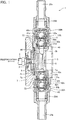
- Fig. 1 is a cross-sectional view showing the main part of a reciprocating pump to which a valve seat 50 and a valve structure according to an embodiment of the present invention are applied.
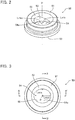
- Fig. 2 is a perspective view showing a valve seat 50 of this reciprocating pump
- Fig. 3 is a plan view showing the valve seat 50.
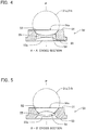
- Fig. 4 is a cross-sectional view taken along the line A-A' of Fig. 3
- Fig. 5 is a cross-sectional view taken along the line B-B' of Fig. 3 .
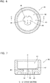
- Fig. 6 is a plan view showing a seat holder 40 of this reciprocating pump
- Fig. 7 is a cross-sectional view taken along the line C-C' of Fig. 6 .
- a metering pump 1 provided with a valve seat 50 and a valve structure according to an embodiment of the present invention has, for example, a rod-like drive shaft 2.
- the drive shaft 2 is reciprocally driven in directions indicated by the arrows in the drawing by the motor driving force, electromagnetic force or the like of the pump main body (not shown).
- a flexible diaphragm 4 is attached to the tip of the drive shaft 2 via an insert bolt 3.
- the diaphragm 4 forms a pump chamber 6 with a pump head 5.
- a transfer fluid including liquid and gas is introduced into the pump chamber 6 and discharged.
- the periphery of a diaphragm 4 is sandwiched between the pump head 5 and a bracket 7 via a cushioning material 7a and a spacer 7b which assist the seal of the diaphragm 4.
- the pump head 5 is formed with a suction port 5a communicating with the lower side of the pump chamber 6 and a discharge port 5b communicating with the upper side of the pump chamber 6.
- a gas-venting path 90 connected to the discharge port 5b is provided above the pump chamber 6, a gas-venting path 90 connected to the discharge port 5b is provided.
- the pump head 5 is formed with a connection port 8 on the suction side of transfer fluid disposed below the suction port 5a and a connection port 9 on the discharge side disposed above the discharge port 5b.
- the connection ports 8 and 9 are in communication with the pump chamber 6 via the suction port 5a and the discharge port 5b, respectively.
- the connection adapters 20A and 20B are connected to the connection ports 8 and 9 via the suction valve 10A and the discharge valve 10B, respectively.
- connection adapters 20A and 20B are respectively connected to a joint 29A connecting the suction side flow path 29a of transfer fluid to the connection adapter 20A and to a joint 29B connecting the discharge side flow path 29b of transfer fluid to the connection adapter 20B.
- suction side flow path 29a and the pump chamber 6 are connected via the joint 29A, the connection adapter 20A, the suction valve 10A, and the suction port 5a on the connection port 8.
- discharge side flow path 29b and the pump chamber 6 are connected via the joint 29B, the connection adapter 20B, the discharge valve 10B, and the discharge port 5b below the connection port 9.
- the suction valve 10A and the discharge valve 10B have, for example, cylindrically formed case bodies 30a and 30b which can be stacked vertically, and two valve balls 31a and 31b built in the case bodies 30a and 30b. Further, the suction and discharge valves 10A and 10B comprises, inside the respective case bodies 30a and 30b, valve guides 32a and 32b provided above the respective valve balls 31a and 31b and valve seats 50 attached to the case bodies 30a and 30b disposed below the valve balls 31 a and 31b. Therefore, each of the suction and discharge valves 10A and 10B of the present embodiment is formed of two stage-valves in which these respective parts are arranged in upper and lower stages. The suction valve 10A and the discharge valve 10B each include a seat holder 40 that supports the lower valve seat 50 and is attached to the lower end side of the case body 30b.
- valve balls 31a and 31b may be made of a material having a specific gravity greater than that of the transfer fluid, for example, ceramic or metal.
- the valve guides 32a and 32b may be formed of a material such as titanium or PVC.
- the valve seat 50 may be formed of a rubber material or the like.
- the valve seat 50 is formed of an annular member having a hole section 54a at the center and having an outer diameter that gradually increases from the upper end to the lower end.
- the valve seat 50 has a circular planar upper end surface 51 and a seating surface 52 formed in a tapered cone-shape or a mortar-shape which fits the external shape of the valve ball 31a, 31b and on which the valve ball 31a, 31b seats, and a lower end surface 53 which has a circular planer shape like the upper end surface 51.
- the hole section 54a of the valve seat 50 communicates the seating surface 52 with the lower end surface 53 to form a seat flow path 54 through which the transfer fluid flows.
- a gas accumulation section 53a is formed between the seat flow path 54 and the lower end surface 53, in which the gas in the transfer fluid accumulates.
- the seat flow path 54 is formed in a predetermined shape such that, for example, the horizontal distance L from the center axis P which crosses the lower end surface 53 at right angle to the seat flow path's inner circumferential surface 55 excluding the seating surface 52 and the lower end surface 53 is not constant over the entire circumference (over 360 degrees) of the seat flow path's inner circumferential surface 55.
- the predetermined shape of the seat flow path 54 is preferably a shape in which the difference between the maximum value Lmax and the minimum value Lmin of the horizontal distance L from the central axis P across the entire circumference of the inner circumferential surface 55 of the seat flow path 54 is, for example, 10% or more and 30% or less, preferably 15% or more and 20% or less of the maximum value Lmax, as shown in Fig. 3 .
- the seat flow path 54 shown in Figs. 2 to 5 is formed to have an elliptical shape at a horizontal cross section.
- a valve seat is generally formed in a circular shape in which both the seating surface and the seat flow path thereof are concentric. Therefore, when the pump device is operated with a gas staying in the lower part of the valve seat or in the gas accumulation section, the gas spreads annularly over the entire circumference of the inner circumferential surface of the seat flow path below the valve ball and pushes the valve ball upward.
- the seat flow path 54 as described above forms a shape that is not constant over the entire circumference of the seat flow path's inner circumferential surface 55.
- the gas in the transfer fluid remained below the valve seat 50 accumulates in the gas accumulation section 53a and the gas ascends from the gas accumulation section 53a to the seat flow path 54, the gas is concentrated and is ascended toward a section on the seat flow path's inner circumferential surface 55 where the horizontal distance L becomes the maximum value rather than a section on the seat flow path's inner circumferential surface 55 where the horizontal distance L becomes the minimum value.
- valve ball 31a, 31b that is seated on and in close contact with the seating surface 52 of the valve seat 50 can be sufficiently lifted up by the gas that passes the seat flow path 54 in a focal manner. Therefore, it becomes possible to exhaust the gas toward the valve guide 32a, 32b. Therefore, according to the valve seat 50 of the present embodiment, the occurrence of gas lock state can be effectively prevented while maintaining the sealing property of the valve ball 31a, 31b.
- the reason why the difference between the maximum value Lmax and the minimum value Lmin of the horizontal distance L from the central axis P with respect to the predetermined shape of the seat flow path 54 is set as 10% to 30% of the maximum value Lmax is explained. That is, when the difference between the maximum value Lmax and the minimum value Lmin of the horizontal distance L is large, the minimum value Lmin needs to be set small to secure the sealability between the valve seat 50 and the valve ball 31a, 31b. In this case, as a result, the area of the seat flow path 54 is reduced. When the flow path area is reduced, the resistance increases when the transfer fluid flows in the seat flow path 54, which is not preferable from the viewpoint of pump performance.
- the seat holder 40 supports the lower end surface 53 of the valve seat 50 disposed at the lowermost position in the suction valve 10A and the discharge valve 10B, and is formed with a cylindrical exterior and a concaved fitting part 41 which fits a lower part of the case body 30b.
- the bottom surface of the fitting portion 41 constitutes a support surface 42 for supporting the lower end surface 53 of the valve seat 50 by surface contact.
- the seat holder 40 has a holder flow path 44 which communicates the support surface 42 with the lower end surface 43 and flowing the transfer fluid inside and communicating with the seat flow path 54 of the valve seat 50.
- the holder flow path 44 has the same central axis P as the central axis P of the valve seat 50.
- the holder flow path 44 has a plurality of ridges 46 that project from the holder flow path's inner circumferential surface 45 toward the central axis P and extend parallel to the central axis P.
- the gas in the transfer fluid transported from the lower side of the seat holder 40 rises concentrating in the areas between respective ridges 46 when it rises in the holder flow path 44, without spreading annually over the entire circumference of the holder flow path's inner circumferential surface 45. Then, the gas locally concentrated between the ridges 46 of the holder flow path's inner circumferential surface 45 enters the gas accumulation section 53a of the valve seat 50 as a plurality of flows, and rises in the seat flow path 54.
- the ridges 46 ensure in advance the flow of the gas accumulated in the gas accumulation section 53a of the valve seat 50. Therefore, it is expected that, in addition to the effect of using the valve seat 50 alone, the situation that the gas spreads annularly over the entire circumference of the seat flow path's inner circumferential surface 55 of the seat flow path 54, causing the force to lift the valve balls 31a and 31b to disperse, can be prevented more reliably.
- the seat holder 40 having the holder flow path's inner circumferential surface 45 on which the ridges 46 are formed is used, the function and effect of the valve seat 50 of the present embodiment can be further enhanced.
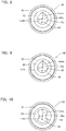
- Figs. 8 to 15 are plan views showing modifications of the valve seat 50 described above.
- the valve seat 50 mentioned above is provided with a seat flow path 54 which has an elliptical shape viewing in the horizontal cross section
- the valve seat 50 may be provided with a seat flow path 54 with the following shapes viewing in the horizontal cross section. That is, the seat flow path 54 may be formed in any one of a drop shape as shown in Fig. 8 , a notch shape (partially deformed circular shape) as shown in Fig. 9 , and a concaved shape as shown in Fig. 10 .
- the seat flow path 54 of the valve seat 50 may be shaped as any one of an eccentric shape (eccentric circular shape) as shown in Fig. 11 , an eyeglass shape (overlapping circular shape) as shown in Fig. 12 , a cross shape as shown in Fig. 13 , a square shape (rectangular shape) as shown in Fig. 14 , and a triangle shape as shown in Fig. 15 .
- the seat flow path 54 is not constant over the entire circumference of the seat flow path inner circumferential surface 55, the gas rises concentrating toward the side of the seat flow path's inner circumferential surface 55 where the horizontal distance L becomes the maximum value rather than the minimum value. Therefore, the occurrence of gas lock is effectively prevented while maintaining the sealing property of the valve ball 31a, 31b.
- the shape of the seat flow path 54 of the valve seat 50 is an elliptical shape or the like in the horizontal cross section; however, various shapes can be employed as long as they are formed such that the horizontal distance L from the central axis P to the seat flow path's inner circumferential surface 55 excluding the seating surface 52 and the lower end surface 53 is not constant over the entire circumference of the seat flow path inner circumferential surface 55 of the seat flow path 54.
Landscapes
- Engineering & Computer Science (AREA)
- General Engineering & Computer Science (AREA)
- Mechanical Engineering (AREA)
- Check Valves (AREA)
- Lift Valve (AREA)
Description
- This invention relates to a valve seat and a valve structure.
- Various pump devices for transferring fluids are known, such as a magnet pump, a metering pump, and a rotary displacement pump. Among them, for example, a reciprocating pump, as a metering pump for introducing a transfer fluid into the pump chamber via a suction valve by the reciprocating motion of a reciprocating member such as a diaphragm, and discharging the transfer fluid from the pump chamber via a discharge valve, uses ball valves as the suction and discharge valves. The ball valve is known to cause a gas lock state when the gas generated from the transfer fluid in the pump chamber and the gas such as air sucked with the transfer fluid remain in the lower part of a valve.
- In order to prevent such a gas lock state, a reciprocating pump provided with an automatic gas-venting mechanism has been proposed (see
Patent Document 1 below). In this reciprocating pump, the passage immediately after the discharge valve is branched into a discharge liquid path extending horizontally to a discharge port and a gas-venting path extending immediately above. Furthermore, a gas-venting valve is provided to the gas-venting path, and the gas-venting valve consists of one ball valve and valve seats positioned at the upper and lower sides thereof. - The gas-venting valve is configured to have an incomplete seal in which the adhesion between the valve ball and the valve seats thereon is intentionally impaired. Therefore, during the suction stroke, liquids and gases from the outside are prevented to leak in by the valve ball and the lower valve seat in the same manner as a normal ball check valve. On the contrary, during the discharge stroke, a small amount of gas mixed in the liquid is efficiently discharged to the outside through the incomplete seal between the valve ball and the upper valve seat. Furthermore, document
US 2014/0119952 A1 discloses a pump in which a discharge side valve has a communication portion.
DocumentUS 6 755 628 B1 discloses a further combination of a valve seat and a valve ball. -
JP Patent Publication No. H9-203380 - Nevertheless, in the conventional reciprocating pump disclosed in the
Patent Document 1, the valve ball and the upper valve seat forms an incomplete seal. Therefore, although it is a preferable form from the viewpoint of preventing gas lock, it was hardly a preferable form from the viewpoint of the sealability of valve ball. - The present invention has been made in view of the above circumstances, and an object thereof is to provide a valve seat and a valve structure capable of preventing the occurrence of gas lock while maintaining the sealability of valve ball.
- Above object is achieved by a valve seat with the features of
claim 1. Additionally, a valve structure with the features ofclaim 4 is provided. A valve seat disclosed herein is a valve seat disposed below a valve ball, comprising
an annular member having in a center thereof a hole section forming a flow path through which a transfer fluid flows,
wherein, the valve seat is arranged so that a central axis of the hole section is set in an up-and-down direction, and comprises a seating surface on which the valve ball seats connected to an upper end of the hole section and fitting to an external shape of the valve ball, and a lower end surface connecting to the lower end of the hole section, and
wherein the hole section is formed in a predetermined shape so that a horizontal distance from the central axis to an inner circumferential surface of the hole section is not constant over an entire circumference of the inner circumferential surface of the hole section. - According to one embodiment of the present invention, the predetermined shape is a shape in which a difference between a maximum value and a minimum value of the horizontal distance throughout the entire circumference of the inner circumferential surface of the hole section is 10% or more and 30% or less of the maximum value.
- According to another embodiment of the present invention, the predetermined shape is one of a partially deformed circular shape, an elliptical shape, a drop shape, a concaved shape, an eccentric circular shape, an overlapping circular shape, a cross shape, a rectangular shape, and a triangle shape, when viewed at a horizontal cross section.
- A valve structure disclosed herein is a valve structure having a valve ball, a valve seat disposed below the valve ball, and a seat holder supporting the valve seat, wherein
the valve seat comprises an annular member having in a center thereof a hole section forming a flow path through which a transfer fluid flows,
the valve seat is arranged so that a central axis of the hole section is set in an up-and-down direction,
the valve seat comprises a seating surface on which the valve ball seats connected to an upper end of the hole section and fitting to an external shape of the valve ball, and a lower end surface connecting to the lower end of the hole section,
the seat holder comprises a holder flow path communicating with the seat flow path;
the hole section is formed in a predetermined shape in which a horizontal distance from the central axis to an inner circumferential surface of the hole section is not constant throughout an entire circumference of the inner circumferential surface of the hole section; and
the holder flow path comprises a plurality of ridges protruding toward the central axis from an inner circumferential surface of the holder flow path, arranging at equal intervals in the circumferential direction and extend parallel to the central axis. - According to one embodiment of the present application, the predetermined shape is a shape in which a difference between a maximum value and a minimum value of the horizontal distance across the entire circumference of the inner circumferential surface of the hole section is 10% or more and 30% or less of the maximum value.
- According to another embodiment of the present application, the predetermined shape is one of a partially deformed circular shape, an elliptical shape, a drop shape, a concaved shape, an eccentric circular shape, an overlapping circular shape, a cross shape, a rectangular shape, and a triangle shape, when viewed at a horizontal cross section.
- According to yet another embodiment of the present application, the valve structure comprises two valve balls arranged vertically, the valve seat is respectively provided below each of the valve balls, and the seat holder supports the lower end surface of the lower valve seat.
- According to the present invention, occurrences of gas lock can be prevented while maintaining the sealability of the valve ball.
-
-
Fig. 1 is a cross-sectional view showing the main part of a reciprocating pump to which a valve seat and a valve structure according to an embodiment of the present invention are incorporated. -
Fig. 2 is a perspective view showing the valve seat of the same reciprocating pump. -
Fig. 3 is a plan view showing the same valve seat. -
Fig. 4 is a cross-sectional view taken along the line A-A' ofFig. 3 . -
Fig. 5 is a cross-sectional view taken along the line B-B' ofFig. 3 . -
Fig. 6 is a plan view showing a seat holder of the reciprocating pump. -
Fig. 7 is a cross-sectional view taken along the line C-C' ofFig. 6 . -
Fig. 8 is a plan view showing a modification of the valve seat. -
Fig. 9 is a plan view showing a modification of the valve seat. -
Fig. 10 is a plan view showing a modification of the valve seat. -
Fig. 11 is a plan view showing a modification of the valve seat. -
Fig. 12 is a plan view showing a modification of the valve seat. -
Fig. 13 is a plan view showing a modification of the valve seat. -
Fig. 14 is a plan view showing a modification of the valve seat. -
Fig. 15 is a plan view showing a modification of the valve seat. - A valve seat and a valve structure according to embodiments of the present invention will be described in detail below with reference to the attached drawings. In the following embodiments, no invention described in each claim is intended to be limited. Nor is it that all the combinations of features described in embodiments are absolutely necessary as means of solving the problems. In addition, although the following embodiments illustrate a case in which it was configured as a metering pump by applying the valve structure of this invention to the suction valve and discharge valve and it includes the valve seat of this invention as a component, the present invention is not limited to pump devices.
-
Fig. 1 is a cross-sectional view showing the main part of a reciprocating pump to which avalve seat 50 and a valve structure according to an embodiment of the present invention are applied.Fig. 2 is a perspective view showing avalve seat 50 of this reciprocating pump, andFig. 3 is a plan view showing thevalve seat 50.Fig. 4 is a cross-sectional view taken along the line A-A' ofFig. 3 , andFig. 5 is a cross-sectional view taken along the line B-B' ofFig. 3 . Furthermore,Fig. 6 is a plan view showing aseat holder 40 of this reciprocating pump, andFig. 7 is a cross-sectional view taken along the line C-C' ofFig. 6 . - As shown in
Fig. 1 , ametering pump 1 provided with avalve seat 50 and a valve structure according to an embodiment of the present invention has, for example, a rod-like drive shaft 2. Thedrive shaft 2 is reciprocally driven in directions indicated by the arrows in the drawing by the motor driving force, electromagnetic force or the like of the pump main body (not shown). Aflexible diaphragm 4 is attached to the tip of thedrive shaft 2 via aninsert bolt 3. - The
diaphragm 4 forms apump chamber 6 with apump head 5. A transfer fluid including liquid and gas is introduced into thepump chamber 6 and discharged. The periphery of adiaphragm 4 is sandwiched between thepump head 5 and abracket 7 via acushioning material 7a and aspacer 7b which assist the seal of thediaphragm 4. Thepump head 5 is formed with asuction port 5a communicating with the lower side of thepump chamber 6 and adischarge port 5b communicating with the upper side of thepump chamber 6. In addition, above thepump chamber 6, a gas-ventingpath 90 connected to thedischarge port 5b is provided. - The
pump head 5 is formed with aconnection port 8 on the suction side of transfer fluid disposed below thesuction port 5a and aconnection port 9 on the discharge side disposed above thedischarge port 5b. Theconnection ports pump chamber 6 via thesuction port 5a and thedischarge port 5b, respectively. Theconnection adapters connection ports suction valve 10A and thedischarge valve 10B, respectively. - The
connection adapters side flow path 29a of transfer fluid to theconnection adapter 20A and to a joint 29B connecting the dischargeside flow path 29b of transfer fluid to theconnection adapter 20B. Thus, the suctionside flow path 29a and thepump chamber 6 are connected via the joint 29A, theconnection adapter 20A, thesuction valve 10A, and thesuction port 5a on theconnection port 8. Further, the dischargeside flow path 29b and thepump chamber 6 are connected via the joint 29B, theconnection adapter 20B, thedischarge valve 10B, and thedischarge port 5b below theconnection port 9. - The
suction valve 10A and thedischarge valve 10B have, for example, cylindrically formedcase bodies valve balls case bodies discharge valves respective case bodies respective valve balls valve seats 50 attached to thecase bodies valve balls discharge valves suction valve 10A and thedischarge valve 10B each include aseat holder 40 that supports thelower valve seat 50 and is attached to the lower end side of thecase body 30b. - The
valve balls valve seat 50 may be formed of a rubber material or the like. - As shown in
Figs. 2 to 5 , thevalve seat 50 is formed of an annular member having ahole section 54a at the center and having an outer diameter that gradually increases from the upper end to the lower end. Thevalve seat 50 has a circular planarupper end surface 51 and aseating surface 52 formed in a tapered cone-shape or a mortar-shape which fits the external shape of thevalve ball valve ball lower end surface 53 which has a circular planer shape like theupper end surface 51. - Furthermore, the
hole section 54a of thevalve seat 50 communicates theseating surface 52 with thelower end surface 53 to form aseat flow path 54 through which the transfer fluid flows. As shown inFigs. 4 and 5 , agas accumulation section 53a is formed between theseat flow path 54 and thelower end surface 53, in which the gas in the transfer fluid accumulates. Theseat flow path 54 is formed in a predetermined shape such that, for example, the horizontal distance L from the center axis P which crosses thelower end surface 53 at right angle to the seat flow path's innercircumferential surface 55 excluding theseating surface 52 and thelower end surface 53 is not constant over the entire circumference (over 360 degrees) of the seat flow path's innercircumferential surface 55. - The predetermined shape of the
seat flow path 54 is preferably a shape in which the difference between the maximum value Lmax and the minimum value Lmin of the horizontal distance L from the central axis P across the entire circumference of the innercircumferential surface 55 of theseat flow path 54 is, for example, 10% or more and 30% or less, preferably 15% or more and 20% or less of the maximum value Lmax, as shown inFig. 3 . Specifically, theseat flow path 54 shown inFigs. 2 to 5 is formed to have an elliptical shape at a horizontal cross section. - Here, a valve seat is generally formed in a circular shape in which both the seating surface and the seat flow path thereof are concentric. Therefore, when the pump device is operated with a gas staying in the lower part of the valve seat or in the gas accumulation section, the gas spreads annularly over the entire circumference of the inner circumferential surface of the seat flow path below the valve ball and pushes the valve ball upward.
- In this case, if the force to lift the valve ball is dispersed over the entire circumference and when the amount of gas mixed in the transfer fluid is large, the compression force of the transfer fluid by the pump device becomes insufficient in many cases, causing a gas lock state.
- On the other hand, in the
valve seat 50 of the present embodiment, while thevalve ball seating surface 52 form a complete seal, theseat flow path 54 as described above forms a shape that is not constant over the entire circumference of the seat flow path's innercircumferential surface 55. For this reason, when the gas in the transfer fluid remained below thevalve seat 50 accumulates in thegas accumulation section 53a and the gas ascends from thegas accumulation section 53a to theseat flow path 54, the gas is concentrated and is ascended toward a section on the seat flow path's innercircumferential surface 55 where the horizontal distance L becomes the maximum value rather than a section on the seat flow path's innercircumferential surface 55 where the horizontal distance L becomes the minimum value. - Thereby, even if the compression force of the transfer fluid by the
metering pump 1 is small, thevalve ball seating surface 52 of thevalve seat 50 can be sufficiently lifted up by the gas that passes theseat flow path 54 in a focal manner. Therefore, it becomes possible to exhaust the gas toward thevalve guide valve seat 50 of the present embodiment, the occurrence of gas lock state can be effectively prevented while maintaining the sealing property of thevalve ball - Here, the reason why the difference between the maximum value Lmax and the minimum value Lmin of the horizontal distance L from the central axis P with respect to the predetermined shape of the
seat flow path 54 is set as 10% to 30% of the maximum value Lmax is explained. That is, when the difference between the maximum value Lmax and the minimum value Lmin of the horizontal distance L is large, the minimum value Lmin needs to be set small to secure the sealability between thevalve seat 50 and thevalve ball seat flow path 54 is reduced. When the flow path area is reduced, the resistance increases when the transfer fluid flows in theseat flow path 54, which is not preferable from the viewpoint of pump performance. - On the other hand, when the difference between the maximum value Lmax and the minimum value Lmin of the horizontal distance L is small, as described above, the effect of concentrating the gas, below the
valve ball circumferential surface 55 where the horizontal distance L becomes the maximum value Lmax becomes small. As a result, the effect of preventing the occurrence of gas lock is reduced, thus not preferable. Therefore, as a result of experiments conducted by the inventor of the present invention in pursuit of an increased preventive effect on the gas lock occurrences while considering the influence on the pump performance, the above stated difference of "10% or more and 30% or less" and preferably "15% or more and 20% or less" of the maximum value Lmax was derived. - As shown in
Figs. 6 and 7 , theseat holder 40 supports thelower end surface 53 of thevalve seat 50 disposed at the lowermost position in thesuction valve 10A and thedischarge valve 10B, and is formed with a cylindrical exterior and a concavedfitting part 41 which fits a lower part of thecase body 30b. The bottom surface of thefitting portion 41 constitutes asupport surface 42 for supporting thelower end surface 53 of thevalve seat 50 by surface contact. - The
seat holder 40 has aholder flow path 44 which communicates thesupport surface 42 with thelower end surface 43 and flowing the transfer fluid inside and communicating with theseat flow path 54 of thevalve seat 50. Theholder flow path 44 has the same central axis P as the central axis P of thevalve seat 50. Theholder flow path 44 has a plurality ofridges 46 that project from the holder flow path's innercircumferential surface 45 toward the central axis P and extend parallel to the central axis P. - In the
seat holder 40 configured in this manner, the gas in the transfer fluid transported from the lower side of theseat holder 40 rises concentrating in the areas betweenrespective ridges 46 when it rises in theholder flow path 44, without spreading annually over the entire circumference of the holder flow path's innercircumferential surface 45. Then, the gas locally concentrated between theridges 46 of the holder flow path's innercircumferential surface 45 enters thegas accumulation section 53a of thevalve seat 50 as a plurality of flows, and rises in theseat flow path 54. - As described above, in the
holder flow path 44 of theseat holder 40, theridges 46 ensure in advance the flow of the gas accumulated in thegas accumulation section 53a of thevalve seat 50. Therefore, it is expected that, in addition to the effect of using thevalve seat 50 alone, the situation that the gas spreads annularly over the entire circumference of the seat flow path's innercircumferential surface 55 of theseat flow path 54, causing the force to lift thevalve balls seat holder 40 having the holder flow path's innercircumferential surface 45 on which theridges 46 are formed is used, the function and effect of thevalve seat 50 of the present embodiment can be further enhanced. -
Figs. 8 to 15 are plan views showing modifications of thevalve seat 50 described above. Although thevalve seat 50 mentioned above is provided with aseat flow path 54 which has an elliptical shape viewing in the horizontal cross section, thevalve seat 50 may be provided with aseat flow path 54 with the following shapes viewing in the horizontal cross section. That is, theseat flow path 54 may be formed in any one of a drop shape as shown inFig. 8 , a notch shape (partially deformed circular shape) as shown inFig. 9 , and a concaved shape as shown inFig. 10 . - In addition, the
seat flow path 54 of thevalve seat 50 may be shaped as any one of an eccentric shape (eccentric circular shape) as shown inFig. 11 , an eyeglass shape (overlapping circular shape) as shown inFig. 12 , a cross shape as shown inFig. 13 , a square shape (rectangular shape) as shown inFig. 14 , and a triangle shape as shown inFig. 15 . - With any of the above shapes, because the
seat flow path 54 is not constant over the entire circumference of the seat flow path innercircumferential surface 55, the gas rises concentrating toward the side of the seat flow path's innercircumferential surface 55 where the horizontal distance L becomes the maximum value rather than the minimum value. Therefore, the occurrence of gas lock is effectively prevented while maintaining the sealing property of thevalve ball - Although the embodiments of this invention were described above, these embodiments were shown as examples and not intended to limit the scope of invention. These novel embodiments can be implemented in other various forms without departing from the scope of the appended claims.
- For example, in the above embodiment, the shape of the
seat flow path 54 of thevalve seat 50 is an elliptical shape or the like in the horizontal cross section; however, various shapes can be employed as long as they are formed such that the horizontal distance L from the central axis P to the seat flow path's innercircumferential surface 55 excluding theseating surface 52 and thelower end surface 53 is not constant over the entire circumference of the seat flow path innercircumferential surface 55 of theseat flow path 54. -
- 1
- metering pump
- 2
- drive shaft
- 4
- diaphragm
- 5
- pump head
- 5a
- suction port
- 5b
- discharge port
- 6
- pump chamber
- 8, 9
- connection port
- 10A
- suction valve
- 10B
- discharge valve
- 20A, 20B
- connection adapter
- 29A, 29B
- joint
- 30a, 30b
- case body
- 31a, 31b
- valve ball
- 32a, 32b
- valve guide
- 40
- seat holder
- 41
- fitting part
- 42
- support surface
- 43
- lower end surface
- 44
- holder flow path
- 45
- holder flow path's inner circumferential surface
- 46
- ridge
- 50
- valve seat
- 51
- upper end surface
- 52
- seating surface
- 53
- lower end surface
- 54
- seat flow path
- 55
- seat flow path's inner circumferential surface
Claims (5)
- A valve seat (50) configured to be disposed below a valve ball (31a, 31b), comprising
an annular member having in a center thereof a hole section (54a) forming a flow path (54) through which a transfer fluid flows,
wherein, the valve seat (50) is arranged so that a central axis (P) of the hole section (54a) is set in an up-and-down direction, and comprises a seating surface (52) which is configured to provide a seat for the valve ball (31a, 31b) and which is connected to an upper end of the hole section (54a) and which is configured to fit to an external shape of the valve ball (31a, 31b) to form a complete seal, and a lower end surface (53) connecting to the lower end of the hole section (54a), and
wherein, the hole section (54a) is formed in a predetermined shape so that a horizontal distance (L) from the central axis (P) to an inner circumferential surface (55) of the hole section (54a) is not constant over an entire circumference of the inner circumferential surface (55) of the hole section (54a). - The valve seat (50) according to claim 1, wherein the predetermined shape is a shape in which a difference between a maximum value (Lmax) and a minimum value (Lmin) of the horizontal distance (L) throughout the entire circumference of the inner circumferential surface (55) of the hole section (54a) is 10% or more and 30% or less of the maximum value (Lmax).
- The valve seat (50) according to claim 1 or 2, wherein the predetermined shape is one of a partially deformed circular shape, an elliptical shape, a drop shape, a concaved shape, an eccentric circular shape, an overlapping circular shape, a cross shape, a rectangular shape, and a triangle shape, when viewed at a horizontal cross section.
- A valve structure comprising a valve ball (31a, 31b), the valve seat (50) according to any one of the preceding claims, and a seat holder (40) supporting the valve seat (50), wherein
the valve ball (31a, 31b) seats on the sealing surface (52) of the valve seat (50)
the seat holder (40) comprises a holder flow path (44) communicating with the flow path (54) of the valve seat (50),
and
the holder flow path (44) comprises a plurality of ridges (46) protruding toward the central axis (P) from an inner circumferential surface (45) of the holder flow path (44), arranging at equal intervals in the circumferential direction and extend parallel to the central axis (P). - The valve structure according to claim 4, comprising two valve balls (31a, 31b) arranged vertically, wherein,
the valve seat (50) is respectively provided below each of the valve balls (31a, 31b), and
the seat holder (40) supports the lower end surface (53) of the lower valve seat (50).
Applications Claiming Priority (1)
| Application Number | Priority Date | Filing Date | Title |
|---|---|---|---|
| PCT/JP2016/087053 WO2018109839A1 (en) | 2016-12-13 | 2016-12-13 | Valve seat and valve structure |
Publications (3)
| Publication Number | Publication Date |
|---|---|
| EP3557099A1 EP3557099A1 (en) | 2019-10-23 |
| EP3557099A4 EP3557099A4 (en) | 2019-12-04 |
| EP3557099B1 true EP3557099B1 (en) | 2021-07-07 |
Family
ID=61452905
Family Applications (1)
| Application Number | Title | Priority Date | Filing Date |
|---|---|---|---|
| EP16924198.1A Active EP3557099B1 (en) | 2016-12-13 | 2016-12-13 | Valve seat and valve structure |
Country Status (6)
| Country | Link |
|---|---|
| US (1) | US10941868B2 (en) |
| EP (1) | EP3557099B1 (en) |
| JP (1) | JP6739545B2 (en) |
| CN (2) | CN108612852B (en) |
| DK (1) | DK3557099T3 (en) |
| WO (1) | WO2018109839A1 (en) |
Families Citing this family (2)
| Publication number | Priority date | Publication date | Assignee | Title |
|---|---|---|---|---|
| EP3557099B1 (en) * | 2016-12-13 | 2021-07-07 | Iwaki Co., Ltd. | Valve seat and valve structure |
| US12560158B2 (en) * | 2023-05-25 | 2026-02-24 | Blue-White Industries, Ltd. | Diaphragm pump |
Family Cites Families (18)
| Publication number | Priority date | Publication date | Assignee | Title |
|---|---|---|---|---|
| US3661167A (en) * | 1970-05-25 | 1972-05-09 | A & D Fabricating Co | Chemical feed pump with improved valve means |
| US3901475A (en) * | 1974-02-28 | 1975-08-26 | Emerson Electric Co | Plastic ball seat member with constant bleed means |
| US4346731A (en) * | 1981-05-26 | 1982-08-31 | Chevron Research Company | Buoyant element check valve for a thermosiphon energy system |
| US5472326B1 (en) * | 1993-03-30 | 1999-03-02 | Leon Tarpley | Valve assemblies for sucker rod operated subsurface pumps |
| US5593292A (en) * | 1994-05-04 | 1997-01-14 | Ivey; Ray K. | Valve cage for a rod drawn positive displacement pump |
| JP2848807B2 (en) | 1996-01-26 | 1999-01-20 | 株式会社イワキ | Reciprocating pump with automatic degassing mechanism |
| JP4365477B2 (en) * | 1999-05-06 | 2009-11-18 | シーケーディ株式会社 | Flow control valve |
| JP2002267032A (en) * | 2001-03-12 | 2002-09-18 | Jiro Matsuyama | Ball check valve |
| US6755628B1 (en) * | 2002-07-16 | 2004-06-29 | Howell's Well Service, Inc. | Valve body for a traveling barrel pump |
| JP2004358574A (en) * | 2003-06-02 | 2004-12-24 | Hirose Technology Kk | Machining method and machining device for valve seat |
| JP5045071B2 (en) * | 2006-11-24 | 2012-10-10 | トヨタ自動車株式会社 | Hydraulic circuit |
| US7444990B1 (en) * | 2007-12-12 | 2008-11-04 | Robert Bosch Gmbh | Fuel line check valve |
| JP5210135B2 (en) * | 2008-12-01 | 2013-06-12 | 日機装エイコー株式会社 | Reciprocating pump with degassing mechanism |
| US8528592B2 (en) * | 2011-02-28 | 2013-09-10 | Idex Health & Science, Llc | Check valve construction |
| JP4977791B1 (en) * | 2011-07-01 | 2012-07-18 | 株式会社タクミナ | Pump and pump operation method |
| JP5629708B2 (en) | 2012-03-06 | 2014-11-26 | 株式会社タクミナ | pump |
| DE102012102088A1 (en) | 2012-03-13 | 2013-09-19 | Prominent Dosiertechnik Gmbh | Positive displacement pump with forced ventilation |
| EP3557099B1 (en) * | 2016-12-13 | 2021-07-07 | Iwaki Co., Ltd. | Valve seat and valve structure |
-
2016
- 2016-12-13 EP EP16924198.1A patent/EP3557099B1/en active Active
- 2016-12-13 DK DK16924198.1T patent/DK3557099T3/en active
- 2016-12-13 WO PCT/JP2016/087053 patent/WO2018109839A1/en not_active Ceased
- 2016-12-13 US US16/468,206 patent/US10941868B2/en active Active
- 2016-12-13 JP JP2018556070A patent/JP6739545B2/en active Active
-
2017
- 2017-07-13 CN CN201710569221.4A patent/CN108612852B/en active Active
- 2017-07-13 CN CN201720846866.3U patent/CN207005305U/en not_active Expired - Fee Related
Also Published As
| Publication number | Publication date |
|---|---|
| JPWO2018109839A1 (en) | 2019-10-24 |
| CN108612852B (en) | 2021-05-07 |
| JP6739545B2 (en) | 2020-08-12 |
| DK3557099T3 (en) | 2021-09-27 |
| US10941868B2 (en) | 2021-03-09 |
| US20190390778A1 (en) | 2019-12-26 |
| CN108612852A (en) | 2018-10-02 |
| WO2018109839A1 (en) | 2018-06-21 |
| CN207005305U (en) | 2018-02-13 |
| EP3557099A1 (en) | 2019-10-23 |
| EP3557099A4 (en) | 2019-12-04 |
Similar Documents
| Publication | Publication Date | Title |
|---|---|---|
| EP1132668A2 (en) | Check valve | |
| CN104053907B (en) | Piston pump for high-pressure cleaning appliance | |
| US7641174B2 (en) | Dome check valve | |
| CN105370550B (en) | Integrally comprise the membrane pump of quick release valve unit | |
| RU2645362C2 (en) | One way valve | |
| US6901961B2 (en) | Double diaphragm pump having a spool valve | |
| EP3557099B1 (en) | Valve seat and valve structure | |
| JPH10512351A (en) | Three-way poppet valve device | |
| CN108474489A (en) | Check valve structure, the jet element and extrusion-type container for having used it | |
| DE10242110A1 (en) | Micro-pump for chemical and biochemical analysis has valves arranged in recesses in the base part and formed by a valve seat and a valve body | |
| EP0943799A2 (en) | Pulsation suppression device for a pump | |
| US11313365B2 (en) | Reciprocating pump designed for preventing valves from being assembled erroneously | |
| CN113767222B (en) | Valve Assemblies for Diaphragm Pumps | |
| US10648582B2 (en) | Check valve and liquid delivery pump | |
| US20040022654A1 (en) | Piston type small discharge pump | |
| JP3576245B2 (en) | Plunger pump | |
| KR200292392Y1 (en) | A cap of reservoir for power-steering system | |
| CN109477472B (en) | Control valve for variable displacement compressor and method of assembling the same | |
| WO2015054598A1 (en) | Scalable pumping mechanism utilizing anti-synchronized poly-diaphragm stack | |
| JP2001248560A (en) | Fluid non-contact pump | |
| EP2084440B1 (en) | Check valve arrangement | |
| JP4878587B2 (en) | Micro pump | |
| WO2020027751A9 (en) | Hydraulic interface apparatus and operation method for microfluidic systems | |
| TWM449887U (en) | Gate valve |
Legal Events
| Date | Code | Title | Description |
|---|---|---|---|
| STAA | Information on the status of an ep patent application or granted ep patent |
Free format text: STATUS: THE INTERNATIONAL PUBLICATION HAS BEEN MADE |
|
| PUAI | Public reference made under article 153(3) epc to a published international application that has entered the european phase |
Free format text: ORIGINAL CODE: 0009012 |
|
| STAA | Information on the status of an ep patent application or granted ep patent |
Free format text: STATUS: REQUEST FOR EXAMINATION WAS MADE |
|
| 17P | Request for examination filed |
Effective date: 20190711 |
|
| AK | Designated contracting states |
Kind code of ref document: A1 Designated state(s): AL AT BE BG CH CY CZ DE DK EE ES FI FR GB GR HR HU IE IS IT LI LT LU LV MC MK MT NL NO PL PT RO RS SE SI SK SM TR |
|
| AX | Request for extension of the european patent |
Extension state: BA ME |
|
| A4 | Supplementary search report drawn up and despatched |
Effective date: 20191106 |
|
| RIC1 | Information provided on ipc code assigned before grant |
Ipc: F04B 53/10 20060101AFI20191030BHEP Ipc: F04B 43/02 20060101ALN20191030BHEP Ipc: F04B 13/00 20060101ALN20191030BHEP Ipc: F04B 53/06 20060101ALI20191030BHEP |
|
| DAV | Request for validation of the european patent (deleted) | ||
| DAX | Request for extension of the european patent (deleted) | ||
| REG | Reference to a national code |
Ref country code: DE Ref legal event code: R079 Ref document number: 602016060507 Country of ref document: DE Free format text: PREVIOUS MAIN CLASS: F16K0001140000 Ipc: F04B0053100000 |
|
| GRAP | Despatch of communication of intention to grant a patent |
Free format text: ORIGINAL CODE: EPIDOSNIGR1 |
|
| STAA | Information on the status of an ep patent application or granted ep patent |
Free format text: STATUS: GRANT OF PATENT IS INTENDED |
|
| INTG | Intention to grant announced |
Effective date: 20210305 |
|
| RIC1 | Information provided on ipc code assigned before grant |
Ipc: F04B 43/02 20060101ALN20210219BHEP Ipc: F04B 53/10 20060101AFI20210219BHEP Ipc: F04B 53/06 20060101ALI20210219BHEP Ipc: F04B 13/00 20060101ALN20210219BHEP |
|
| GRAS | Grant fee paid |
Free format text: ORIGINAL CODE: EPIDOSNIGR3 |
|
| GRAA | (expected) grant |
Free format text: ORIGINAL CODE: 0009210 |
|
| STAA | Information on the status of an ep patent application or granted ep patent |
Free format text: STATUS: THE PATENT HAS BEEN GRANTED |
|
| AK | Designated contracting states |
Kind code of ref document: B1 Designated state(s): AL AT BE BG CH CY CZ DE DK EE ES FI FR GB GR HR HU IE IS IT LI LT LU LV MC MK MT NL NO PL PT RO RS SE SI SK SM TR |
|
| REG | Reference to a national code |
Ref country code: GB Ref legal event code: FG4D |
|
| REG | Reference to a national code |
Ref country code: AT Ref legal event code: REF Ref document number: 1408835 Country of ref document: AT Kind code of ref document: T Effective date: 20210715 |
|
| REG | Reference to a national code |
Ref country code: DE Ref legal event code: R096 Ref document number: 602016060507 Country of ref document: DE |
|
| REG | Reference to a national code |
Ref country code: IE Ref legal event code: FG4D |
|
| REG | Reference to a national code |
Ref country code: DK Ref legal event code: T3 Effective date: 20210922 |
|
| REG | Reference to a national code |
Ref country code: LT Ref legal event code: MG9D |
|
| REG | Reference to a national code |
Ref country code: NL Ref legal event code: MP Effective date: 20210707 |
|
| REG | Reference to a national code |
Ref country code: AT Ref legal event code: MK05 Ref document number: 1408835 Country of ref document: AT Kind code of ref document: T Effective date: 20210707 |
|
| PG25 | Lapsed in a contracting state [announced via postgrant information from national office to epo] |
Ref country code: NL Free format text: LAPSE BECAUSE OF FAILURE TO SUBMIT A TRANSLATION OF THE DESCRIPTION OR TO PAY THE FEE WITHIN THE PRESCRIBED TIME-LIMIT Effective date: 20210707 Ref country code: NO Free format text: LAPSE BECAUSE OF FAILURE TO SUBMIT A TRANSLATION OF THE DESCRIPTION OR TO PAY THE FEE WITHIN THE PRESCRIBED TIME-LIMIT Effective date: 20211007 Ref country code: PT Free format text: LAPSE BECAUSE OF FAILURE TO SUBMIT A TRANSLATION OF THE DESCRIPTION OR TO PAY THE FEE WITHIN THE PRESCRIBED TIME-LIMIT Effective date: 20211108 Ref country code: HR Free format text: LAPSE BECAUSE OF FAILURE TO SUBMIT A TRANSLATION OF THE DESCRIPTION OR TO PAY THE FEE WITHIN THE PRESCRIBED TIME-LIMIT Effective date: 20210707 Ref country code: FI Free format text: LAPSE BECAUSE OF FAILURE TO SUBMIT A TRANSLATION OF THE DESCRIPTION OR TO PAY THE FEE WITHIN THE PRESCRIBED TIME-LIMIT Effective date: 20210707 Ref country code: ES Free format text: LAPSE BECAUSE OF FAILURE TO SUBMIT A TRANSLATION OF THE DESCRIPTION OR TO PAY THE FEE WITHIN THE PRESCRIBED TIME-LIMIT Effective date: 20210707 Ref country code: LT Free format text: LAPSE BECAUSE OF FAILURE TO SUBMIT A TRANSLATION OF THE DESCRIPTION OR TO PAY THE FEE WITHIN THE PRESCRIBED TIME-LIMIT Effective date: 20210707 Ref country code: AT Free format text: LAPSE BECAUSE OF FAILURE TO SUBMIT A TRANSLATION OF THE DESCRIPTION OR TO PAY THE FEE WITHIN THE PRESCRIBED TIME-LIMIT Effective date: 20210707 Ref country code: BG Free format text: LAPSE BECAUSE OF FAILURE TO SUBMIT A TRANSLATION OF THE DESCRIPTION OR TO PAY THE FEE WITHIN THE PRESCRIBED TIME-LIMIT Effective date: 20211007 Ref country code: SE Free format text: LAPSE BECAUSE OF FAILURE TO SUBMIT A TRANSLATION OF THE DESCRIPTION OR TO PAY THE FEE WITHIN THE PRESCRIBED TIME-LIMIT Effective date: 20210707 Ref country code: RS Free format text: LAPSE BECAUSE OF FAILURE TO SUBMIT A TRANSLATION OF THE DESCRIPTION OR TO PAY THE FEE WITHIN THE PRESCRIBED TIME-LIMIT Effective date: 20210707 |
|
| PG25 | Lapsed in a contracting state [announced via postgrant information from national office to epo] |
Ref country code: PL Free format text: LAPSE BECAUSE OF FAILURE TO SUBMIT A TRANSLATION OF THE DESCRIPTION OR TO PAY THE FEE WITHIN THE PRESCRIBED TIME-LIMIT Effective date: 20210707 Ref country code: LV Free format text: LAPSE BECAUSE OF FAILURE TO SUBMIT A TRANSLATION OF THE DESCRIPTION OR TO PAY THE FEE WITHIN THE PRESCRIBED TIME-LIMIT Effective date: 20210707 Ref country code: GR Free format text: LAPSE BECAUSE OF FAILURE TO SUBMIT A TRANSLATION OF THE DESCRIPTION OR TO PAY THE FEE WITHIN THE PRESCRIBED TIME-LIMIT Effective date: 20211008 |
|
| REG | Reference to a national code |
Ref country code: DE Ref legal event code: R097 Ref document number: 602016060507 Country of ref document: DE |
|
| PLBE | No opposition filed within time limit |
Free format text: ORIGINAL CODE: 0009261 |
|
| STAA | Information on the status of an ep patent application or granted ep patent |
Free format text: STATUS: NO OPPOSITION FILED WITHIN TIME LIMIT |
|
| PG25 | Lapsed in a contracting state [announced via postgrant information from national office to epo] |
Ref country code: SM Free format text: LAPSE BECAUSE OF FAILURE TO SUBMIT A TRANSLATION OF THE DESCRIPTION OR TO PAY THE FEE WITHIN THE PRESCRIBED TIME-LIMIT Effective date: 20210707 Ref country code: SK Free format text: LAPSE BECAUSE OF FAILURE TO SUBMIT A TRANSLATION OF THE DESCRIPTION OR TO PAY THE FEE WITHIN THE PRESCRIBED TIME-LIMIT Effective date: 20210707 Ref country code: RO Free format text: LAPSE BECAUSE OF FAILURE TO SUBMIT A TRANSLATION OF THE DESCRIPTION OR TO PAY THE FEE WITHIN THE PRESCRIBED TIME-LIMIT Effective date: 20210707 Ref country code: EE Free format text: LAPSE BECAUSE OF FAILURE TO SUBMIT A TRANSLATION OF THE DESCRIPTION OR TO PAY THE FEE WITHIN THE PRESCRIBED TIME-LIMIT Effective date: 20210707 Ref country code: CZ Free format text: LAPSE BECAUSE OF FAILURE TO SUBMIT A TRANSLATION OF THE DESCRIPTION OR TO PAY THE FEE WITHIN THE PRESCRIBED TIME-LIMIT Effective date: 20210707 Ref country code: AL Free format text: LAPSE BECAUSE OF FAILURE TO SUBMIT A TRANSLATION OF THE DESCRIPTION OR TO PAY THE FEE WITHIN THE PRESCRIBED TIME-LIMIT Effective date: 20210707 |
|
| 26N | No opposition filed |
Effective date: 20220408 |
|
| PG25 | Lapsed in a contracting state [announced via postgrant information from national office to epo] |
Ref country code: MC Free format text: LAPSE BECAUSE OF FAILURE TO SUBMIT A TRANSLATION OF THE DESCRIPTION OR TO PAY THE FEE WITHIN THE PRESCRIBED TIME-LIMIT Effective date: 20210707 Ref country code: IT Free format text: LAPSE BECAUSE OF FAILURE TO SUBMIT A TRANSLATION OF THE DESCRIPTION OR TO PAY THE FEE WITHIN THE PRESCRIBED TIME-LIMIT Effective date: 20210707 |
|
| REG | Reference to a national code |
Ref country code: CH Ref legal event code: PL |
|
| GBPC | Gb: european patent ceased through non-payment of renewal fee |
Effective date: 20211213 |
|
| REG | Reference to a national code |
Ref country code: BE Ref legal event code: MM Effective date: 20211231 |
|
| PG25 | Lapsed in a contracting state [announced via postgrant information from national office to epo] |
Ref country code: LU Free format text: LAPSE BECAUSE OF NON-PAYMENT OF DUE FEES Effective date: 20211213 Ref country code: IE Free format text: LAPSE BECAUSE OF NON-PAYMENT OF DUE FEES Effective date: 20211213 Ref country code: GB Free format text: LAPSE BECAUSE OF NON-PAYMENT OF DUE FEES Effective date: 20211213 |
|
| PG25 | Lapsed in a contracting state [announced via postgrant information from national office to epo] |
Ref country code: BE Free format text: LAPSE BECAUSE OF NON-PAYMENT OF DUE FEES Effective date: 20211231 |
|
| PG25 | Lapsed in a contracting state [announced via postgrant information from national office to epo] |
Ref country code: LI Free format text: LAPSE BECAUSE OF NON-PAYMENT OF DUE FEES Effective date: 20211231 Ref country code: CH Free format text: LAPSE BECAUSE OF NON-PAYMENT OF DUE FEES Effective date: 20211231 |
|
| P01 | Opt-out of the competence of the unified patent court (upc) registered |
Effective date: 20230523 |
|
| PG25 | Lapsed in a contracting state [announced via postgrant information from national office to epo] |
Ref country code: CY Free format text: LAPSE BECAUSE OF FAILURE TO SUBMIT A TRANSLATION OF THE DESCRIPTION OR TO PAY THE FEE WITHIN THE PRESCRIBED TIME-LIMIT Effective date: 20210707 |
|
| PG25 | Lapsed in a contracting state [announced via postgrant information from national office to epo] |
Ref country code: HU Free format text: LAPSE BECAUSE OF FAILURE TO SUBMIT A TRANSLATION OF THE DESCRIPTION OR TO PAY THE FEE WITHIN THE PRESCRIBED TIME-LIMIT; INVALID AB INITIO Effective date: 20161213 |
|
| PG25 | Lapsed in a contracting state [announced via postgrant information from national office to epo] |
Ref country code: MK Free format text: LAPSE BECAUSE OF FAILURE TO SUBMIT A TRANSLATION OF THE DESCRIPTION OR TO PAY THE FEE WITHIN THE PRESCRIBED TIME-LIMIT Effective date: 20210707 |
|
| PG25 | Lapsed in a contracting state [announced via postgrant information from national office to epo] |
Ref country code: MT Free format text: LAPSE BECAUSE OF FAILURE TO SUBMIT A TRANSLATION OF THE DESCRIPTION OR TO PAY THE FEE WITHIN THE PRESCRIBED TIME-LIMIT Effective date: 20210707 |
|
| PGFP | Annual fee paid to national office [announced via postgrant information from national office to epo] |
Ref country code: DE Payment date: 20241218 Year of fee payment: 9 |
|
| PG25 | Lapsed in a contracting state [announced via postgrant information from national office to epo] |
Ref country code: TR Free format text: LAPSE BECAUSE OF FAILURE TO SUBMIT A TRANSLATION OF THE DESCRIPTION OR TO PAY THE FEE WITHIN THE PRESCRIBED TIME-LIMIT Effective date: 20210707 |
|
| PGFP | Annual fee paid to national office [announced via postgrant information from national office to epo] |
Ref country code: DK Payment date: 20251223 Year of fee payment: 10 |
|
| PGFP | Annual fee paid to national office [announced via postgrant information from national office to epo] |
Ref country code: FR Payment date: 20251223 Year of fee payment: 10 |